US5659573A - Method and apparatus for coherent reception in a spread-spectrum receiver - Google Patents
Method and apparatus for coherent reception in a spread-spectrum receiverDownload PDFInfo
- Publication number
- US5659573A US5659573AUS08/317,501US31750194AUS5659573AUS 5659573 AUS5659573 AUS 5659573AUS 31750194 AUS31750194 AUS 31750194AUS 5659573 AUS5659573 AUS 5659573A
- Authority
- US
- United States
- Prior art keywords
- signal
- late
- power
- timing
- early
- Prior art date
- Legal status (The legal status is an assumption and is not a legal conclusion. Google has not performed a legal analysis and makes no representation as to the accuracy of the status listed.)
- Expired - Lifetime
Links
- 238000001228spectrumMethods0.000titleclaimsabstractdescription52
- 230000001427coherent effectEffects0.000titleclaimsabstractdescription41
- 238000000034methodMethods0.000titleclaimsabstractdescription30
- 238000004891communicationMethods0.000claimsabstractdescription59
- 239000013074reference sampleSubstances0.000claimsdescription31
- 239000000872bufferSubstances0.000claimsdescription11
- 238000005070samplingMethods0.000claimsdescription9
- 238000012935AveragingMethods0.000claimsdescription4
- 238000001914filtrationMethods0.000claimsdescription2
- 230000008878couplingEffects0.000claims1
- 238000010168coupling processMethods0.000claims1
- 238000005859coupling reactionMethods0.000claims1
- 230000007480spreadingEffects0.000abstractdescription24
- 238000001514detection methodMethods0.000abstractdescription16
- 238000005562fadingMethods0.000abstractdescription12
- 230000004044responseEffects0.000abstractdescription5
- 239000000523sampleSubstances0.000description18
- 239000011159matrix materialSubstances0.000description17
- 230000005540biological transmissionEffects0.000description8
- 230000007774longtermEffects0.000description7
- 238000010586diagramMethods0.000description6
- 238000007476Maximum LikelihoodMethods0.000description5
- 238000013459approachMethods0.000description5
- 230000000875corresponding effectEffects0.000description5
- 238000013461designMethods0.000description5
- 230000010363phase shiftEffects0.000description5
- 230000008901benefitEffects0.000description4
- 230000011664signalingEffects0.000description4
- 230000007704transitionEffects0.000description4
- 101100370058Escherichia coli (strain K12) tolC geneProteins0.000description3
- 230000008859changeEffects0.000description3
- 230000003111delayed effectEffects0.000description3
- 230000006872improvementEffects0.000description3
- 238000012937correctionMethods0.000description2
- 230000006735deficitEffects0.000description2
- 230000000694effectsEffects0.000description2
- 238000000605extractionMethods0.000description2
- 238000010897surface acoustic wave methodMethods0.000description2
- 230000003044adaptive effectEffects0.000description1
- 239000000654additiveSubstances0.000description1
- 230000000996additive effectEffects0.000description1
- 230000003190augmentative effectEffects0.000description1
- 230000015572biosynthetic processEffects0.000description1
- 230000015556catabolic processEffects0.000description1
- 230000010267cellular communicationEffects0.000description1
- 239000002131composite materialSubstances0.000description1
- 230000001276controlling effectEffects0.000description1
- 230000002596correlated effectEffects0.000description1
- 239000013078crystalSubstances0.000description1
- 238000006731degradation reactionMethods0.000description1
- 230000001934delayEffects0.000description1
- 239000000284extractSubstances0.000description1
- 238000001413far-infrared spectroscopyMethods0.000description1
- 238000005259measurementMethods0.000description1
- 239000013307optical fiberSubstances0.000description1
- 238000012545processingMethods0.000description1
- 238000003786synthesis reactionMethods0.000description1
Images


Classifications
- H—ELECTRICITY
- H04—ELECTRIC COMMUNICATION TECHNIQUE
- H04B—TRANSMISSION
- H04B1/00—Details of transmission systems, not covered by a single one of groups H04B3/00 - H04B13/00; Details of transmission systems not characterised by the medium used for transmission
- H04B1/69—Spread spectrum techniques
- H04B1/707—Spread spectrum techniques using direct sequence modulation
- H04B1/7073—Synchronisation aspects
- H04B1/7087—Carrier synchronisation aspects
- H—ELECTRICITY
- H04—ELECTRIC COMMUNICATION TECHNIQUE
- H04B—TRANSMISSION
- H04B1/00—Details of transmission systems, not covered by a single one of groups H04B3/00 - H04B13/00; Details of transmission systems not characterised by the medium used for transmission
- H04B1/69—Spread spectrum techniques
- H04B1/707—Spread spectrum techniques using direct sequence modulation
- H—ELECTRICITY
- H04—ELECTRIC COMMUNICATION TECHNIQUE
- H04J—MULTIPLEX COMMUNICATION
- H04J3/00—Time-division multiplex systems
- H04J3/02—Details
- H04J3/06—Synchronising arrangements
- H04J3/0602—Systems characterised by the synchronising information used
- H04J3/0605—Special codes used as synchronising signal
- H—ELECTRICITY
- H04—ELECTRIC COMMUNICATION TECHNIQUE
- H04L—TRANSMISSION OF DIGITAL INFORMATION, e.g. TELEGRAPHIC COMMUNICATION
- H04L25/00—Baseband systems
- H04L25/02—Details ; arrangements for supplying electrical power along data transmission lines
- H04L25/0202—Channel estimation
- H—ELECTRICITY
- H04—ELECTRIC COMMUNICATION TECHNIQUE
- H04L—TRANSMISSION OF DIGITAL INFORMATION, e.g. TELEGRAPHIC COMMUNICATION
- H04L27/00—Modulated-carrier systems
- H04L27/18—Phase-modulated carrier systems, i.e. using phase-shift keying
- H04L27/22—Demodulator circuits; Receiver circuits
- H04L27/227—Demodulator circuits; Receiver circuits using coherent demodulation
- H04L27/2275—Demodulator circuits; Receiver circuits using coherent demodulation wherein the carrier recovery circuit uses the received modulated signals
- H04L27/2276—Demodulator circuits; Receiver circuits using coherent demodulation wherein the carrier recovery circuit uses the received modulated signals using frequency multiplication or harmonic tracking
- H—ELECTRICITY
- H04—ELECTRIC COMMUNICATION TECHNIQUE
- H04B—TRANSMISSION
- H04B1/00—Details of transmission systems, not covered by a single one of groups H04B3/00 - H04B13/00; Details of transmission systems not characterised by the medium used for transmission
- H04B1/69—Spread spectrum techniques
- H04B1/707—Spread spectrum techniques using direct sequence modulation
- H04B1/7097—Interference-related aspects
- H04B1/711—Interference-related aspects the interference being multi-path interference
- H04B1/7115—Constructive combining of multi-path signals, i.e. RAKE receivers
- H04B1/7117—Selection, re-selection, allocation or re-allocation of paths to fingers, e.g. timing offset control of allocated fingers
- H—ELECTRICITY
- H04—ELECTRIC COMMUNICATION TECHNIQUE
- H04B—TRANSMISSION
- H04B2201/00—Indexing scheme relating to details of transmission systems not covered by a single group of H04B3/00 - H04B13/00
- H04B2201/69—Orthogonal indexing scheme relating to spread spectrum techniques in general
- H04B2201/707—Orthogonal indexing scheme relating to spread spectrum techniques in general relating to direct sequence modulation
- H04B2201/70703—Orthogonal indexing scheme relating to spread spectrum techniques in general relating to direct sequence modulation using multiple or variable rates
- H04B2201/70705—Rate detection
Definitions
- the present inventionrelates to communication systems which employ spread-spectrum signals and, more particularly, to a method and apparatus for coherent communication reception in a spread-spectrum communication system.
- Communication systemstake many forms.
- One type of communication systemis a multiple access spread-spectrum system.
- a modulation techniqueis utilized in which a transmitted signal is spread over a wide frequency band within the communication channel. The frequency band is much wider than the minimum bandwidth required to transmit the information being sent.
- a voice signalfor example, can be sent with amplitude modulation (AM) in a bandwidth only twice that of the information itself.
- AMamplitude modulation
- FMlow deviation frequency modulation
- single sideband AMalso permit information to be transmitted in a bandwidth comparable to the bandwidth of the information itself.
- the modulation of a signal to be transmittedoften includes taking a baseband signal (e.g., a voice channel) with a bandwidth of only a few kilohertz, and distributing the signal to be transmitted over a frequency band that may be many megahertz wide. This is accomplished by modulating the signal to be transmitted with the information to be sent and with a wideband encoding signal.
- a baseband signale.g., a voice channel
- Direct sequence modulationa carrier signal is modulated by a digital code sequence whose bit rate is much higher than the information signal bandwidth.
- Informationi.e. the message signal consisting of voice and/or data
- One methodis to add the information to the spreading code before it is used for spreading modulation. It will be noted that the information being sent must be in a digital form prior to adding it to the spreading code, because the combination of the spreading code and the information, a binary code, typically involves modulo-2 addition. Alternatively, the information or message signal may be used to modulate a carder before spreading it.
- a spread-spectrum systemmay be designed as a direct sequence code division multiple access (DS-CDMA) system.
- DS-CDMAdirect sequence code division multiple access
- communication between two communication unitsis accomplished by spreading each transmitted signal over the frequency band of the communication channel with a unique user spreading code.
- transmitted signalsare in the same frequency band of the communication channel and are separated only by unique user spreading codes.
- unique user spreading codespreferably are orthogonal to one another such that the cross-correlation between the spreading codes is approximately zero.
- Particular transmitted signalscan be retrieved from the communication channel by despreading a signal representative of the sum of signals in the communication channel with a user spreading code related to the particular transmitted signal which is to be retrieved from the communication channel. Further, when the user spreading codes are orthogonal to one another, the received signal can be correlated with a particular user spreading code such that only the desired user signal related to the particular spreading code is enhanced while the other signals for all of the other users are not enhanced.
- spreading codesinclude but are not limited to pseudonoise (PN) codes and Walsh codes.
- PNpseudonoise
- a Walsh codecorresponds to a single row or column of the Hadamard matrix.
- spreading codescan be used to channel code data signals.
- the data signalsare channel coded to improve performance of the communication system by enabling transmitted signals to better withstand the effects of various channel impairments, such as noise, fading, and jamming.
- channel codingreduces the probability of bit error, and/or reduces the required signal to noise ratio usually expressed as error bits per noise density (i.e., E b /N o which is defined as the ratio of energy per information-bit to noise-spectral density), to recover the signal at the cost of expending more bandwidth than would otherwise be necessary to transmit the data signal.
- E b /N owhich is defined as the ratio of energy per information-bit to noise-spectral density
- Walsh code wordscan be used to channel code a data signal prior to modulation of the data signal for subsequent transmission.
- PN spreading codescan be used to channel code a data signal.
- channel codingalone may not provide the required signal to noise ratio for some communication system designs which require the system to be able to handle a particular number of simultaneous communications (all having a minimum signal to noise ratio).
- This design constraintmay be satisfied, in some instances, by designing the communication system to coherently detect transmitted signals rather than using non-coherent reception techniques.
- a coherent receiverrequires less signal to noise ratio (in E b /N o ) than that required by a non-coherent receiver having the same bit error rate (i.e., a particular design constraint denoting an acceptable interference level). Roughly, speaking, there is a three deciBel (dB) difference between them for the Rayleigh fading channel.
- dBdeciBel
- One such method for facilitating coherent detection of transmitted signalsis to use a pilot signal.
- the forward channel, or down-link(i.e., from base station to mobile unit) may be coherently detected, if the base station transmits a pilot signal. Subsequently, all the mobile units use the pilot channel signal to estimate the channel phase and magnitude parameters.
- the reverse channel, or up-link(i.e., from mobile to base station)
- using such a common pilot signalis not feasible.
- those of ordinary skill in the artoften assume that only non-coherent detection techniques are suitable for up-link communication.
- a “fat” fingeris a finger of a demodulator circuit that straddles more than one ray having less than a chip of differential delay; where a "fat” finger occurs without some form of compensation, it is possible for the finger to center on the weaker ray, with consequent degradation in signal quality. There thus remains a need for an improved coherent communication system which compensates for these and other problems.
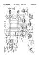
- FIG. 1is a block diagram showing a preferred embodiment communication system in accordance with the present invention.
- FIG. 2illustrates a preferred embodiment communication channel frame structure for use with the communication system shown in FIG. 1.
- FIG. 3is a block diagram showing a preferred embodiment receiver frontend and sampler for use in the receiver shown in FIG. 1.
- FIG. 4is a block diagram showing a preferred embodiment demodulation circuitry for use in the receiver shown in FIG. 1.
- FIG. 5is a block diagram showing a preferred embodiment buffer and timing control for use in the receiver shown in FIG. 1.
- FIG. 6is a block diagram showing a preferred embodiment power estimator and timing control circuitry for use in the receiver shown in FIG. 1.
- FIG. 7illustrates a communication channel frame structure at different rates for use in the communication system shown in FIG. 1.
- FIG. 8is a block diagram showing a second embodiment demodulation circuitry for use in the receiver shown in FIG. 1.
- Data-based channel estimationmay be implemented as decision-directed or non-decision-directed.
- the channel estimatormust operate at low signal-to-noise ratios and the fading is relatively fast. As a result, the decision-directed approach is not appropriate due to the high decision error rate.
- a non-decision-directed methodsuch as the one described in the article by A. J. Viterbi and A. M, Viterbi, "Nonlinear Estimation of PSK-Modulated Carrier Phase with Application to Burst Digital Transmission," IEEE Trans. on Info. Theory, Vol.
- phase ambiguitye.g., 180° ambiguity for binary phase shift key (BPSK) signaling or 90° ambiguity for quadrature phase shift key (QPSK) signaling
- BPSKbinary phase shift key
- QPSKquadrature phase shift key
- Reference-symbol-based channel estimationis described as follows. Reference symbols known to the receiver are inserted into a sequence of information bearing data bits, which may be coded symbols. At the receiver, the received signal samples corresponding to the reference symbols are used to generate a channel estimate. Because the reference symbols are known to the coherent direct-sequence spread spectrum receiver, there are no decision errors and the resulting channel estimate does not have a phase ambiguity. As a result, a robust communication system with non-differentially coded signaling is provided.
- the inserted reference symbolscan be organized in blocks or uniformly distributed. For a flat fading channel, it is desirable to insert reference symbols periodically and uniformly in the data stream. For a DS-CDMA up-link With a RAKE receiver for frontend processing, we can treat the output of each RAKE "finger" as being a flat faded signal. Thus, the preferred embodiment communication system will uniformly insert one reference symbol for every M coded data symbols.
- RAKE receiversperform a continuous, detailed measurement of the multipath characteristic of a received signal. This knowledge is then exploited to combat the selective fading by detecting signal from each path individually, using a correlation method, and algebraically combining those echo signals into a single detected signal.
- traffic channel data bits 102are input to an encoder at a particular bit rate. (e.g., 9.6 kilobit/second).
- the input traffic channel data bitscan include either voice converted to data by a vocoder, pure data (including video), or a combination of the two types of data.
- the encoderencodes the input data bits 102 into data bits at a fixed encoding rate (1/r) with an encoding algorithm which facilitates subsequent maximum likelihood decoding of received data samples into data bits (e.g. convolutional or block coding algorithms).
- the encoderencodes input data bits 102 (e.g., 192 input data bits that were received at a rate of 9.6 kilobits/second) at a fixed encoding rate of one data bit to three coded data bits (i.e., 1/3) such that the encoder outputs data bits, e.g., 576 data bits output at a 28.8 kilobit/second rate.
- interleaverwhich organizes the data bits into blocks (i.e., frames) and block interleaves the input data bits.
- the data bitsare individually input into a matrix which defines a predetermined size block of data bits.
- the data bitsare input into locations within the matrix so that the matrix is filled in a column by column manner.
- the data bitsare individually output from locations within the matrix so that the matrix is emptied in a row by row manner.
- the matrixis a square matrix having a number of rows equal to the number of columns; however, other matrix forms can be chosen to increase the output interleaving distance between the consecutively input non-interleaved data bits.
- the interleaved data bits 110are output by the encoder/interleaver 104 at the same data bit rate that they were input to the interleaver (e.g., 28.8 kb/s (kilobits/second)).
- the predetermined size of the block of data bits defined by the matrixis derived from the maximum number of data bits which can be transmitted at a coded bit rate within a predetermined length transmission block. For example, if data bits are output from the encoder at a 28.8 kilobits/second rate, and if the predetermined length of the transmission block is 20 milliseconds, then the predetermined size of the block of data bits is 28.8 kilobits/second times 20 milliseconds which equals 576 data bits which defines an 18 by 32 matrix.
- the interleaved data bits 110are then input to a reference bit inserter 112 which inserts L known reference bits (generated by synch bit generator 111) for every M interleaved data bits 110.
- Lknown reference bits
- Meight bit group
- each inserted reference bitis a zero bit.
- L and Mcould be any other value without departing from the scope and spirit of the present invention.
- the reference bitscould be any known sequence such as all one bits or several one bits followed by several zero bits without departing from the scope and spirit of the present invention.
- An example of a block (i.e., frame) of reference-coded data bits 114 ready for spreading consisting of 48 bitsis shown in FIG. 2 (where each d represents a data bit and each r represents a reference bit).
- the reference-coded data bits 114are input to a modulating portion 116 of the communication system.
- the data bits 114are received into a buffer 118, from which the real and imaginary portions of the bitstream are subsequently read out and separately spread with a Walsh code Wj and PN code sequences PNi via multipliers 120-121.
- Wj and PN code sequences PNimay be used for the real and imaginary branches.
- the Walsh codeserves, as a user specific sequence of symbols or unique user code.
- the reference-coded datastreamarrives at modulating portion 116 at a rate of 19.2 kilobits/second.
- a higher fixed symbol ratee.g., 1228.8 kilosymbols/second, also referred to as 1.2288 Megachips/second.
- the spread symbol streamis then rotated via multiplier 122 by ⁇ /4 every chip; for alternative modulations like QPSK this step is omitted.
- the symbol streamsare then FIR (finite impulse response) filtered to reduce out of band energy below a set value, converted to an analog signal stream, and further low pass filtered via filter/DACs (digital to analog converters) 124, 125.
- filter/DACsdigital to analog converters
- the signals from the two symbol streamsare quadrature modulated and summed via multipliers 126, 127 and summer 128; alternatively, the signals could be combined via direct digital synthesis.
- the modulated signalis amplified by LPA (linear power amplifier) 129 and provided to antenna 130 for transmission over the communication channel 131.
- LPAlinear power amplifier
- the preferred embodiment receiver 135 of the communication systemreceives the transmitted spread-spectrum signal from over the communication channel 131 through antenna 137.
- the received reference symbol coded spread spectrum signalis filtered and downconverted by an analog frontend 139, and inputted to demodulator circuitry 140.
- Antenna 136 and demodulator 138are similarly provided for space diversity reception of the signal.
- the spread spectrum signalis next sampled into despread samples 148 by despreader and, sampler 146.
- These samples 148include both reference and data samples, so a reference sample extractor 150 is used to separate the reference sample information from the data signal samples.
- the reference samples 152are output to a channel estimator 154, while the remaining data samples 158 from the despread sampled signal 148 are output to a coherent detector 160 for later coherent detection of data symbols 162 from the data samples 158.
- the detected data symbols 162-164are summed in summer 180 with detected data symbols from other fingers or diversity paths and output to the decoding portion 182 of the communication system.
- the resulting despread sampled signal 148is sampled at a predetermined rate and output to the reference sample extractor 150 (e.g., 19.2 kilosamples/second so that a sequence of 64 samples of the received spread-spectrum signal is despread to and/or is represented by a single data sample).
- the reference sample extractor 150preferably extracts the reference samples 152 from the despread sampled signal 148 and outputs the reference samples 152 to a channel estimator 154.
- the data samples 158 from the despread sampled signal 148are output to a coherent detector 160 for later coherent detection of data symbols.
- the channel estimator 154 outputis used in conjunction with only standard synchronization methods.
- the rate of phase rotation of the received signalmay be as high as several kilohertz, impairing signal acquisition.
- the reference samples 152 and data samples 158are also input to a synchronization device, preferably including frequency offset estimator 172 and a timing control 176.
- the frequency offset estimator 172derives an estimate of an offset frequency, such as might be caused by large Doppler shifts or an imprecise oscillator, which estimate drives a frequency locked loop to send a control signal 174 to adjust the frequency of a local oscillator, digital phase corrector (rotator) or similar circuit of the analog frontend 139 or sampler/despreader 146. This permits the residual frequency offset to be locked-in at less than 50 Hz (Hertz), greatly improving signal acquisition and detection.
- timing control 176which derives and combines power estimates of the reference and data signals 152, 158 (that may be unbiased), and then are differenced and filtered and input to a delay locked loop to control timing so as to center the finger on the long term average mean ray arrival time.
- a fast timing (i.e., typically less than one chip) correctionis also achieved by comparing the timing difference outputs of multiple timing branches and picking the branch having the maximum value, enabling demodulation to follow the peak power. This correction is accomplished by controlling a gate 179 via a fast timing compensation signal 178.
- the timing control 176, frequency offset estimator 172, gate 179 and their operationsare described in more detail in connection with FIGS. 3 though 7 below.
- the channel estimator 154correlates the extracted reference samples 152 of the selected timing branch with a known reference sequence of data samples to obtain unbiased, but noisy, channel estimates.
- these noisy estimatesmay be passed through a low-pass filter, which may be fixed or adaptive, to remove the high frequency noise components.
- power controlmay also be used to enhance overall system performance.
- the power control algorithmsmay be very similar to the algorithms used in non-coherent communication systems.
- the preferred embodiment power control algorithmpreferably includes estimating received power every 1.25 ms (milliseconds) (i.e., each time slot), or every 12 reference information samples, i.e., every 36 encoded data samples or 24 total received signal samples.
- the power estimatemay be calculated with several different techniques. One technique is to compute a channel estimate with a power estimator 146 simply using the 12 reference signal samples (i.e., reference samples 152 from reference sample extractor 150) in each 24 sample length block. The square of the magnitude of the channel estimate is then output by the power estimator 166 as the power estimate 168.
- the coherent detector 160multiplies the remaining data samples 158 from the despread sampled signal 148 by the conjugate of the channel estimates 156 to generate coherently detected symbols 162.
- receiver branches 138, 140 and antennae 136, 137, respectivelymay be employed to achieve improved reception through space diversity.
- All N diversity receiver brancheswould operate in substantially the same manner to retrieve data samples from the received spread-spectrum signal in communication channel 131 as the above described receiver branch 140.
- the outputs 162 through 164 of the N receiver branchespreferably are input to an adder 180 which diversity combines the input data symbols into a composite stream of coherently detected data symbols 181.
- the individual data symbols 181 which form soft decision dataare then input into a decoding portion 182 including a deinterleaver which deinterleaves the input soft decision data (i.e., detected data symbols) 181 at the individual data level.
- the soft decision data 181are individually input into a matrix which defines a predetermined size block of soft decision data.
- the soft decision dataare input into locations within the matrix so that the matrix is filled in a row by row manner.
- the deinterleaved soft decision dataare individually output from locations within the matrix so that the matrix is emptied in a column by column manner.
- the deinterleaved soft decision dataare output by the deinterleaver at the same rate that they were input (e.g., 28.8Diacs/second).
- the predetermined size of the block of soft decision data defined by the matrixis derived from the maximum rate of sampling data samples from the spread-spectrum signal received within the predetermined length transmission block.
- the deinterleaved soft decision datais then input to a decoder which uses maximum likelihood decoding techniques to generate estimated traffic channel data symbols 185.
- the maximum likelihood decoding techniquesmay be augmented by using an algorithm which is substantially similar to a Viterbi decoding algorithm.
- the decoderuses a group of the individual soft decision data to form a set of soft decision transition metrics for use at each particular time state of the maximum likelihood sequence estimation decoder.
- the number of soft decision data in the group used to form each set of soft decision transition metricscorresponds to the number of data bit pairs at the output of the convolutional encoder 104 generated from each input data bit 102.
- the number of soft decision transition metrics in each setis equal to two raised to the power of the number of soft decision data in each group. For example, when a 1/3 convolutional encoder is used in the transmitter 101, three data bits are generated from each input data bit 102.
- decoder 182uses groups of three individual soft decision data to form eight soft decision transition metrics for use at each time state in the maximum likelihood sequence estimation decoder.
- the estimated data symbols 185are generated at a rate related to the rate that the soft decision data are input to the decoder and the fixed rate used to originally encode the input data bits 102 (e.g., if the soft decision data are input at 28.8 Telecs/second and the original encoding rate was 1/3 then estimated data symbols 185 are output at a rate of 9600 bits/second). This information can also be used in determining the occupancy of the various time slots within each frame, e.g., to determine when less than a full rate signal is being received.
- FIGS. 3 through 6a more detailed description of a preferred embodiment of the receiver 135 is illustrated. For purposes of clarity, only one numeral is used to identify each element appearing in more than one figure.
- the embodiment illustratedis specifically designed for a ⁇ /4 QPSK (or QPSK if zero rotation) modulated signal.
- the present inventionis not limited in application to QPSK signal reception, but may apply to any modulated signal that can be coherently received, including but not limited to OQPSK and BPSK (binary phase shift keying) signals.
- FIG. 3illustrates the analog portion of receiver 135.
- An IF (intermediate frequency, downconverted) version of the spread spectrum signalis bandpass filtered with filter 301 about a frequency band of interest.
- the filtered outputis gain controlled by AGC (automatic gain control) 302, then separated into imaginary (Im) and real (Re) signal streams by LO (local oscillator) 305.
- AGCautomatic gain control
- LOlocal oscillator
- the Im and Re signalsare then image reject (possibly matched) filtered preferably by a SAW (surface acoustic wave) filter and a FIR filter following each A/D (which together accomplish most of the match, with subsequent FIRs serving to eliminate out-of-band energy including the image signal), and then digitized by ND (analog-to-digital) converters 311 and 312 of sampler 310.
- the Im and Re digitized IF sample streams 313 and 314are outputted to each of the fingers of demodulator 140, as well as to the AGC control circuitry.
- the AGC control circuitryis typical of that found in spread spectrum receivers, being used to optimize the performance of the A/Ds 311 and 312. This control circuitry operates by squaring and summing the digitized IF sample streams, inputting the resultant signal to a difference amplifier 315, and averaging the output to generate the AGC control signal.
- FIGS. 4 through 6the demodulator section of one of receiver 135's fingers is further illustrated.
- ⁇ /4 QPSK modulationis used, the Im and Re digitized samples 313 and 314 are counter rotated ⁇ /4 via multiplier/phase rotator 420; this advantageously permits the ⁇ /4 QPSK signal to be shifted at baseband rather than at RF (radio frequency).
- the samplesare received in a buffer/timing control device 421, which is illustrated in more detail in FIG. 5.
- Each symbolis oversampled, preferably 8 times the chip rate of 1.2288 Mchip/s.
- Registers 510 and 512will thus have 8 consecutive samples of the same chip (i.e., spread symbol) period that can be tapped or addressed, e.g.
- timing branch input controller 520In the preferred embodiment three different timing branch input leads 422 through 424 are connected via controller 520.
- the controller 520is responsive to a timing control signal 177 ("G") to adjust the addressing of the buffers 510, 512 so as to keep the signal optimized on a middle, "on time” lead 422.
- Gtiming control signal 177
- the other two leads 423, 424sample what should optimally be either a late (or retarded replica) or an early sample (or advanced replica) of the symbol having approximately the same power.
- the controllerserves to adjust the taps or lead addresses one sample (i.e., one buffer register) prior to reading the next chip (i.e., every 1/1.2288 ⁇ s) until the center tap 514 again has the maximum energy (i.e., is the "on time” branch). This is accomplished in the preferred embodiment, illustrated in FIG. 6 and discussed more fully below, by performing a differencing operation between the early and late timing branch power estimations.
- despreader 425includes multipliers 426 and 427 for multiplying the Re and Im samples by the PN and Walsh code sequences (despread signals), thus correlating the received signal with the assigned spreading codes.
- PNi and PNqcomplex spreading sequence
- duplicate multipliersshould be used in despreading the complex received spread symbols.
- Despreader 425is replicated in each timing branch, so that early, late and on-time despread signals (samples) are formed.
- the resulting signals in the on-time branchare integrated over each sample period by integrate and dump circuits 428 and 429, so as to output I (in-phase) and Q (quadrature phase) samples 431 and 432, corresponding to the real and imaginary quadrature phase samples Re and Im.
- the preferred embodiment of the reference sample extraction circuit 150operates by multiplying each of the I and Q samples 431 and 432 by synch(I) (via multipliers/correlators 433 and 437) and synch(Q) (via multipliers 434 and 436) signals and summing the respective I and Q branches via adders 435 and 438.
- the synch(I) and synch(Q)are the complex conjugate of the known reference (synch) symbols, for example an all zero bits or all one bits symbol.
- the purpose for this structureis to derive a noisy estimate of the channel response from the I and Q components. Since a DS-CDMA up-link can be viewed as multiple flat-fading channels, for each flat fading channel the received signal after despreading can be expressed as:
- r(n)is the received sample at n (or nT where T is the interval at which the signal of interest, e.g., reference samples, is sampled after despreading)
- a(n)is the corresponding transmitted symbol
- h(n)is a low-pass random complex variable characterizing the fading channel
- z(n)is the additive noise or interference, which is approximately white and Gaussian.
- the first component of equation 4is equivalent to the reference sample I component output 439, while the second component of equation 4 is equivalent to the reference sample Q component output 440, when r(n) is a received reference sample.
- Both reference sample I & Q outputs 439 and 440are fed to channel estimator 154, while the I and Q data samples (r(n)) are fed to coherent detector 160.
- the channel estimator 154can determine, using the reference sample I and Q outputs 439 and 440, the instantaneous phase and magnitude of a channel for purposes of coherent detection, it is, without more, vulnerable to problems of frequency drift.
- Relatively stable, large frequency offsets(which are easiest to correct) may arise from influences such as an inaccurate oscillator causing an imperfect lock on the transmitter/receiver clock, and large Doppler shifts.
- Such offsets in conventional communication systemsare typically corrected by means of a phase-locked loop (PLL).
- PLLphase-locked loop
- a frequency locked loopFLL
- the frequency offset estimator 172includes two portions, each basing its estimates on the respective data (431 and 432) and reference (439 and 440) output signals.
- an offset frequency detector 445includes two delays 446 and 447, two multipliers 448 and 449, and an adder 450. The detector operates by multiplying a delayed I component signal 439 by Q component signal 440 in multiplier 448, and multiplying a delayed Q component signal 440 by I component signal 439 in multiplier 449.
- the summed output of the detectorcan be expressed as:
- f estis a scaled estimate of the offset-frequency.
- the offset frequencycan also be estimated using the information bearing (data) received signal samples 431 and 432. Because the actually transmitted data bits are not known, there will be a 90° (or 180° for BPSK) phase ambiguity in the phase estimate. To eliminate this ambiguity, a complex 4-th power operation is performed on each received signal sample (squaring for BPSK) in circuit 442. The real (I) and imaginary (Q) components of the fourth powered samples are sent to an offset frequency detector 443 which is identical to the offset-frequency detector 445 for the reference samples. In this manner, offset-frequency detector 443 also generates a scaled estimate of the offset-frequency.
- Either of the scaled estimates of the offset frequency from these two detectors 443, 445can be used to drive the frequency-locked loop. On the other hand, they can be combined to form an even better offset-frequency estimate, which in turn is used to drive the frequency-locked loop. If the frequency estimates from the reference samples 439, 440 and data samples 431,432 are denoted by f d and f r , respectively, a combined estimate can be obtained as:
- w r and w dare two weighting factors, whose values are selected to maximize the ratio of the squared value of the detected offset frequency and its variance.
- the optimal values of these weighting coefficientsare functions of the sample signal to noise ratio, which a skilled artisan will know how to derive.
- w rw d .
- These weighting factorsare applied to the detector 443, 445 outputs via multipliers 451, 452, and the weighted outputs are summed via adder 453.
- the outputs of the offset frequency detectors of all the fingerscan be combined via combiner 454 to generate a scaled overall offset-frequency estimate.
- These outputscan also be weighted, e.g., rejecting outputs with a value beneath a threshold, and/or having a scaled weighting increasing with magnitude.
- This scaled overall offset-frequency estimateis sent to a loop-filter 456 via gate 455 (the function of which is described below).
- the loop filtermay consist of a scaling constant and an integrator.
- the first order FLLis adequate for most applications; a higher order FLL, which has poles in the loop filter, may be useful in some special cases.
- the design of the FLL and parameter selectionwill be well known to persons skilled in the art. (See, e.g., F. M. Gardner, "Characteristics of Frequency-Tracking Loops," in Phase-Locked Loops (Editors W. C. Lindsey and C. M.
- the output "I" 457 voltage of the loop filteris used to correct the frequency offset by feeding it to LO 305.
- the output 457may be fed to a digital phase corrector (rotator), such as phase rotator 420; an example of such is illustrated in FIG. 8, in which output 457 is fed into phase rotator 420 rather than LO 305.
- rotatordigital phase corrector
- reference sample 439, 440 and data sample 431, 432 outputsis power estimator 467, a preferred embodiment of which is illustrated in FIG. 6.
- the reference sample outputs 439, 440are filtered by FIR 611 to further remove noise.
- the filtered outputis squared in circuit 612, the squared magnitude yielding a reference sample (coherent) signal power estimate.
- the coherent signal power estimatemay be sufficient for timing control
- improved controlcan be obtained by also forming a signal power estimate based on data sample outputs 431,432.
- these outputs 431,432are complex multiplied to the fourth power in circuit 615 (which may be a complex power estimator), and then accumulated or averaged by accumulator 616 for each reference sample interval (i.e., 3 data samples per reference sample in the embodiment above, or 1.25 ms/slot ⁇ (42 samples/slot ⁇ 3 pair of reference samples) ⁇ 89.3 ⁇ s (microseconds)).
- the square root of the magnitude of the accumulator outputis derived by circuit 617, which provides a signal power estimate of the noncoherent branch.
- both signal power estimatesare weighted, for example by maximizing the ratio of the power estimate to its variance, and summed in combiner/adder 618 to yield a power estimate for the timing branch.
- Timing control 176serves to compensate both for timing drift having a slower rate of change (typically on the order of one chip per several seconds or more), as well as for timing changes at a relatively faster rate of change (approximately 0.1 to 1.0 seconds) within a one chip interval.
- Timing driftis compensated for by differencing the power estimates of two or more timing branches.
- "on time,” “late” and “early” branches 602-606one may advantageously use the late and early branches 604, 606 to obtain the power estimates for samples with sample timing t n + ⁇ and t n - ⁇ , where t n is the "on time” sample timing.
- the difference between the estimates of the late and early timing branches, determined by differencer 632,indicates the direction of the drift of the correct timing. The difference can be time averaged, and if the difference is zero on average, the sampling timing is correct and no adjustment is made.
- a delay-locked loop filter 634If the filtered difference is positive or negative, a delay-locked loop filter 634 generates a control signal 177 ("G") which causes controller 520 (see FIG. 5) to adjust the sampling timing towards + ⁇ or - ⁇ from the previous sampling time, i.e., where the correct sampling time is located.
- Gcontrol signal 177
- controller 520see FIG. 5
- the maximum slew rate requiredmay be 2 to 5 times faster in order to account for very fast trains and initial missettings. The result of this long term timing compensation is to center the finger on the long term average mean ray arrival time.
- Short interval timingis also desirable to compensate for circumstances such as a "fat finger," or one which acquires two rays within a chip of each other that fade independently.
- a preferred approach for fast timing adjustmentis to determine by a comparator 636 which of the gated power estimations from timing branches 602, 604, or 606 has the maximum value.
- a short time constante.g., less than 1 sec
- Low pass filter(not shown) may be optionally used to reduce the noise components of the gated power estimations prior to comparison.
- Comparator 636outputs a control signal 178 ("F") to the selector or gate 179, which switches between the various timing branch Data and Reference sample outputs, depending on which has the maximum estimated power. In the case illustrated in FIG.
- gates 462 and 463 of selector 179are closed to the extractor outputs K r and K d of the early timing branch 606, indicating that the maximum signal power has been determined to be received from tap 513 of buffer 421.
- a window limit cyclewill typically be centered about the value determined by the long term timing compensation branch, and that this limit is typically no more than about ⁇ 0.5 chips. No more movement is needed because typically another finger will have been assigned to the adjacent-in-time energy.
- FIG. 7illustrates one such signal, having a 20 ms frame with sixteen 1.25 ms slots per frame.
- the unused slotsmay be advantageously gated or masked out, so as to reduce noise and provide an improved channel estimate.
- the signaluses 2, 4, 8 or all 16 slots is decided by the rate required; but, except for full rate, the slots used may differ from frame to frame depending on the rate.
- the slot group for the 1/8 rateis a subset of the slot group for the 1/4 rate which is a subset of the slot group for the 1/2 rate. This arrangement is shown in FIG. 7, where the shaded intervals represent transmitted energy.
- the integrate & dump circuits 428 and 429 of FIG. 4are set to span a 1.25 ms slot interval.
- Slot detector 465receives this output (i.e., outputs 431, 432, 439 and 440), as well as similar outputs from other fingers, and may even receive information from the frame decoder, and uses these outputs to determine which intervals may be summed and which must be masked out.
- the occupancy (power) estimate of slot detector 465may be delayed until the frame decoding decision and its slot occupancy determination is made.
- each framehas at least two occupied slots
- the occupancy of the next 2can be estimated by comparing the power in those slots to that of the first two. This estimate should be more heavily weighted for the stronger power fingers.
- a simple procedurewould be to make the rate decision only with input from the strongest finger (or an average of the two strongest if they are approximately equal).
- An alternativeis to power sum the estimates for an overall estimate. The expected noise power is typically larger than the sample power at this point; so, by averaging over the 24 samples of the next two candidate slots, 6.9 dB improvement in the estimate is achieved which should be good enough to be correctly estimating slot occupancy most of the time if the strongest finger is used to pace the estimate.
- the procedureis preferably continued to insure this is a correct decision.
- the next 4 slotswould be averaged and, if large enough, the initial 1/8 rate decision is changed. This can be continued up to an examination of the full rate interval powers.
- a similar gating arrangementis used for the frequency offset estimator 172.
- the output of the offset frequency detectors 443, 445must be weighted, and gated via gate 455.
- the objective of the frequency locked loopis to compensate for slow variations of large but relatively stable frequency offsets without introducing unacceptable additional noise.
- the frequency-locked looptherefore performs a long term averaged control to accommodate frequency offsets and steady-state Doppler frequency shifts (such as moving toward a base station in a Rician fading radio channel).
- the long term controlcan take advantage of the rate decision of the decoder 182 by gating the signal input to the FLL filter 456.
- the modulator, antennas and demodulator portions of the preferred embodiment communication system as describedwere directed to CDMA spread-spectrum signals transmitted over a radio communication channel.
- the encoding and decoding techniques described and claimed hereincan also be adapted for use in other types of transmission systems like those based on time division multiple access (TDMA) and frequency division multiple access (FDMA).
- the communication channelcould alternatively be an electronic data bus, wireline, optical fiber link, satellite link, or any other type of communication channel.
Landscapes
- Engineering & Computer Science (AREA)
- Computer Networks & Wireless Communication (AREA)
- Signal Processing (AREA)
- Power Engineering (AREA)
- Mobile Radio Communication Systems (AREA)
Abstract
Description
r(n)=h(n)a(n)+z(n) (eq. 1)
h(n)=r(n)a.sub.ref *(n) (eq. 2)
h.sub.I (n)+jh.sub.Q (n)=(r.sub.I (n)+jr.sub.Q (n))(a.sub.refI (n)-ja.sub.refQ (n)) (eq 3)
=(r.sub.I (n)a.sub.refI (n)+r.sub.Q (n)a.sub.refQ (n))+j(r.sub.Q (n)a.sub.refI (n)-r.sub.I (n)a.sub.refQ (n)) (eq. 4)
f.sub.est =h.sub.I (n-1)h.sub.Q (n)-h.sub.Q (n-1)h.sub.I (n)(eq. 5)
f.sub.c =w.sub.r f.sub.r +w.sub.d f.sub.d (eq. 6)
Claims (16)
Priority Applications (13)
| Application Number | Priority Date | Filing Date | Title |
|---|---|---|---|
| US08/317,501US5659573A (en) | 1994-10-04 | 1994-10-04 | Method and apparatus for coherent reception in a spread-spectrum receiver |
| US08/396,453US5619524A (en) | 1994-10-04 | 1995-02-28 | Method and apparatus for coherent communication reception in a spread-spectrum communication system |
| EP95930789AEP0732022B1 (en) | 1994-10-04 | 1995-07-31 | Method and apparatus for coherent communication reception in a spread-spectrum communication system |
| DE69531042TDE69531042T2 (en) | 1994-10-04 | 1995-07-31 | METHOD AND DEVICE FOR COHERENTLY RECEIVING MESSAGES IN A SPREADING SPECTRUM TRANSMISSION SYSTEM |
| BR9506385ABR9506385A (en) | 1994-10-04 | 1995-07-31 | Process for receiving coherent diffuse spectrum from coherent diffuse spectrum |
| CA002176945ACA2176945C (en) | 1994-10-04 | 1995-07-31 | Method and apparatus for coherent communication reception in a spread-spectrum communication system |
| KR1019960702911AKR100227452B1 (en) | 1994-10-04 | 1995-07-31 | Method and apparatus for coherent communication reception in a spread spectrum communication system |
| PCT/US1995/009774WO1996010879A1 (en) | 1994-10-04 | 1995-07-31 | Method and apparatus for coherent communication reception in a spread-spectrum communication system |
| CNB951909908ACN1149802C (en) | 1994-10-04 | 1995-07-31 | Method and device for coherent communication reception in spread spectrum communication system |
| PL95314846APL314846A1 (en) | 1994-10-04 | 1995-07-31 | Method of and apparatus for cherent telecommunicational receiving in a distributed spectrum telecommunication system |
| JP51172896AJP3679415B2 (en) | 1994-10-04 | 1995-07-31 | Coherent communication receiving method and apparatus in spread spectrum communication system |
| IL11483695AIL114836A (en) | 1994-10-04 | 1995-08-04 | Method and apparatus for coherent spread-spectrum reception |
| FI962326AFI113227B (en) | 1994-10-04 | 1996-06-04 | Method and apparatus for coherent reception of communication in a spread spectral communication system |
Applications Claiming Priority (1)
| Application Number | Priority Date | Filing Date | Title |
|---|---|---|---|
| US08/317,501US5659573A (en) | 1994-10-04 | 1994-10-04 | Method and apparatus for coherent reception in a spread-spectrum receiver |
Related Child Applications (1)
| Application Number | Title | Priority Date | Filing Date |
|---|---|---|---|
| US08/396,453Continuation-In-PartUS5619524A (en) | 1994-10-04 | 1995-02-28 | Method and apparatus for coherent communication reception in a spread-spectrum communication system |
Publications (1)
| Publication Number | Publication Date |
|---|---|
| US5659573Atrue US5659573A (en) | 1997-08-19 |
Family
ID=23233935
Family Applications (1)
| Application Number | Title | Priority Date | Filing Date |
|---|---|---|---|
| US08/317,501Expired - LifetimeUS5659573A (en) | 1994-10-04 | 1994-10-04 | Method and apparatus for coherent reception in a spread-spectrum receiver |
Country Status (1)
| Country | Link |
|---|---|
| US (1) | US5659573A (en) |
Cited By (90)
| Publication number | Priority date | Publication date | Assignee | Title |
|---|---|---|---|---|
| US5799011A (en)* | 1996-03-29 | 1998-08-25 | Motorola, Inc. | CDMA power control channel estimation using dynamic coefficient scaling |
| US5822364A (en)* | 1996-03-29 | 1998-10-13 | Matsushita Electric Industrial Co., Ltd. | Receiving apparatus for spectrum spread system |
| US5844935A (en)* | 1995-11-07 | 1998-12-01 | Nec Corporation | CDMA Receiver |
| WO1998038742A3 (en)* | 1997-02-14 | 1998-12-17 | Dspc Israel Ltd | Method and apparatus for acquiring and tracking the sampling phase of a signal |
| US5867532A (en)* | 1995-03-31 | 1999-02-02 | Sony Corporation | Data reception apparatus, data transmission apparatus and method thereof |
| US5896425A (en)* | 1997-02-24 | 1999-04-20 | At&T Wireless Services Inc | Non-uniformly spaced tones for synchronization waveform |
| US5914981A (en)* | 1997-02-24 | 1999-06-22 | At&T Wireless Services Inc. | Method to indicate synchronization lock of a remote station with a base station for a discrete multitone spread spectrum communications system |
| US5943375A (en)* | 1997-02-06 | 1999-08-24 | At&T Wireless Services Inc. | Method to indicate synchronization lock of a remote station with a base station |
| WO1999044303A1 (en)* | 1998-02-26 | 1999-09-02 | Stanford Telecommunications, Inc. | Quasi-optimal receiver for tracking and acquisition of a split spectrum pn gps c/a signal |
| US5982807A (en)* | 1997-03-17 | 1999-11-09 | Harris Corporation | High data rate spread spectrum transceiver and associated methods |
| US6031865A (en)* | 1997-08-04 | 2000-02-29 | Motorola, Inc. | Rapidly decorrelating spreading sequences for DS-CDMA transceivers |
| US6034997A (en)* | 1997-08-19 | 2000-03-07 | Stanford Telecommunications, Inc. | Trellis decoding with multiple symbol noncoherent detection and interleaving to combat frequency offset |
| WO2000002397A3 (en)* | 1998-07-07 | 2000-03-30 | Samsung Electronics Co Ltd | Device and method for cancelling code interference in a cdma communication system |
| WO2000030312A1 (en)* | 1998-11-12 | 2000-05-25 | Ericsson Inc. | Frequency correction in a pilot symbol assisted demodulator |
| WO2000010301A3 (en)* | 1998-10-13 | 2000-06-02 | Ericsson Telefon Ab L M | Signalling transmission using phase rotation techniques in a digital communications system |
| US6081549A (en)* | 1997-01-10 | 2000-06-27 | Yozan Inc. | Phase correction method and apparatus for spectrum spread wireless communication receiver |
| US6085104A (en)* | 1998-03-25 | 2000-07-04 | Sharp Laboratories Of America, Inc. | Pilot aided, time-varying finite impulse response, adaptive channel matching receiving system and method |
| US6084932A (en)* | 1997-02-06 | 2000-07-04 | At&T Wireless Services Inc. | Method to indicate synchronization lock of a remote station with a base station for a discrete multitone spread spectrum communications system |
| US6091760A (en)* | 1998-06-29 | 2000-07-18 | L-3 Communications Corporation | Non-recursively generated orthogonal PN codes for variable rate CDMA |
| US6111865A (en)* | 1997-05-30 | 2000-08-29 | Qualcomm Incorporated | Dual channel slotted paging |
| WO2000025435A3 (en)* | 1998-10-27 | 2000-10-12 | Siemens Ag | Method for controlling memory access in rake receivers with early-late tracking |
| GB2349555A (en)* | 1999-04-29 | 2000-11-01 | Roke Manor Research | Delay lock loops |
| US6144649A (en)* | 1997-02-27 | 2000-11-07 | Motorola, Inc. | Method and apparatus for acquiring a pilot signal in a CDMA receiver |
| US6161209A (en)* | 1997-03-28 | 2000-12-12 | Her Majesty The Queen In Right Of Canada, As Represented By The Minister Of Industry Through The Communications Research Centre | Joint detector for multiple coded digital signals |
| FR2795257A1 (en)* | 1999-06-15 | 2000-12-22 | Koninkl Philips Electronics Nv | Phase detector for phase locked loop includes calculator calculating input-output products in order to detect phase shift |
| US6192066B1 (en)* | 1997-07-25 | 2001-02-20 | Kabushiki Kaisha Toshiba | Spread spectrum communication apparatus and rake receiver |
| EP1039653A3 (en)* | 1999-03-23 | 2001-05-09 | Matsushita Electric Industrial Co., Ltd. | Apparatus and method for receiving and despreading DS-CDMA signals |
| US6275518B1 (en)* | 1995-01-27 | 2001-08-14 | Hitachi, Ltd. | Frequency hopping radio LAN system and frequency hopping control method |
| WO2001073968A1 (en)* | 2000-03-28 | 2001-10-04 | Interdigital Technology Corporation | Cdma system which uses pre-rotation before transmission |
| US6333953B1 (en)* | 1997-07-21 | 2001-12-25 | Ericsson Inc. | System and methods for selecting an appropriate detection technique in a radiocommunication system |
| WO2001059937A3 (en)* | 2000-01-26 | 2002-01-31 | Qualcomm Inc | Multipath doppler-adjusted frequency tracking loop |
| US6363102B1 (en)* | 1999-04-23 | 2002-03-26 | Qualcomm Incorporated | Method and apparatus for frequency offset correction |
| US20020037029A1 (en)* | 2000-08-15 | 2002-03-28 | Masahiko Shimizu | Synchronization tracking circuit |
| US6373862B1 (en)* | 1997-12-12 | 2002-04-16 | Texas Instruments Incorporated | Channel-aided, decision-directed delay-locked loop |
| US20020051434A1 (en)* | 1997-10-23 | 2002-05-02 | Ozluturk Fatih M. | Method for using rapid acquisition spreading codes for spread-spectrum communications |
| US6389060B1 (en)* | 1996-12-26 | 2002-05-14 | Sony Corporation | CDMA receiver |
| EP1206045A1 (en)* | 2000-11-10 | 2002-05-15 | Alcatel | Method of correcting frequency error |
| US6411661B1 (en)* | 1999-05-07 | 2002-06-25 | The Aerospace Corporation | Digital timing recovery loop for GMSK demodulators |
| US6421389B1 (en)* | 1999-07-16 | 2002-07-16 | Time Domain Corporation | Baseband signal converter for a wideband impulse radio receiver |
| US6426949B1 (en)* | 1997-06-18 | 2002-07-30 | Yozan, Inc. | Signal reception apparatus for DS-CDMA communication system |
| US20020105973A1 (en)* | 2001-02-02 | 2002-08-08 | Mitsubishi Wireless Communications, Inc | Systems and methods for improved time slot synchronization using enhanced two-times oversampling |
| US20020131483A1 (en)* | 2001-01-23 | 2002-09-19 | Aris Papasakellariou | Spreading factor estimation system and method |
| WO2002027956A3 (en)* | 2000-09-28 | 2002-10-03 | Nortel Networks Ltd | Method and system for estimating frequency offset and phase rotation correction in cdma systems |
| WO2002091609A1 (en)* | 2001-05-10 | 2002-11-14 | Siemens Aktiengesellschaft | Method and system for regulating the frequency of a rake receiver |
| US20020181626A1 (en)* | 2001-04-24 | 2002-12-05 | Lucent Technologies Inc. | Doppler corrected communications receiver and method of removing doppler frequency shift |
| WO2002029978A3 (en)* | 2000-10-04 | 2002-12-12 | Ericsson Telefon Ab L M | Method and apparatus for automatic frequency control in a cdma receiver |
| US6563858B1 (en) | 1998-01-16 | 2003-05-13 | Intersil Americas Inc. | Method of performing antenna diversity in spread spectrum in wireless local area network |
| US20030108136A1 (en)* | 2001-11-30 | 2003-06-12 | Fan Wang | Time recovery circuit and method for synchronizing timing of a signal in a receiver to timing of the signal in a transmitter |
| US6587517B1 (en)* | 1998-12-23 | 2003-07-01 | Nortel Networks Limited | Multi-stage receiver |
| US6594286B2 (en)* | 1999-08-12 | 2003-07-15 | Qualcomm Incorporated | Method and apparatus for coherent demodulation in communication system employing a potentially gated pilot signal |
| US6603801B1 (en) | 1998-01-16 | 2003-08-05 | Intersil Americas Inc. | Spread spectrum transceiver for use in wireless local area network and having multipath mitigation |
| WO2003069793A1 (en)* | 2002-02-12 | 2003-08-21 | Interdigital Technology Corporation | Receiver for wireless telecommunication stations and method |
| US6628736B1 (en)* | 1999-11-10 | 2003-09-30 | Koninklijke Philips Electronics N.V. | Estimating the optimal sampling instant in a TDMA packet transmission system |
| US20030214978A1 (en)* | 2002-05-20 | 2003-11-20 | Bois Karl Joseph | Encoded multi-access bus system and method |
| US6674792B1 (en)* | 1999-09-21 | 2004-01-06 | Nec Corporation | Demodulation of receiver with simple structure |
| US20040009757A1 (en)* | 2002-07-09 | 2004-01-15 | Parvathanathan Subrahmanya | Frequency tracking using inner and outer loops |
| US20040015308A1 (en)* | 2001-12-29 | 2004-01-22 | Lg Electronics Inc. | Method of estimating doppler frequency shift and method of transmitting data using the same |
| US6683903B1 (en) | 2000-04-27 | 2004-01-27 | Motorola, Inc. | Method and apparatus for synchronization within a spread-spectrum communication system |
| US20040017842A1 (en)* | 2001-03-15 | 2004-01-29 | Alcatel | Method of recovering digital signal packet timing |
| US6687285B1 (en) | 1999-03-19 | 2004-02-03 | Qualcomm Incorporated | Method and apparatus for supervising the performance of a quick paging channel in a dual event slotted paging system |
| US20040029609A1 (en)* | 2002-04-29 | 2004-02-12 | Interdigital Technology Corporation | Simple and robust digital code tracking loop for wireless communication systems |
| US20040057506A1 (en)* | 2001-10-01 | 2004-03-25 | Interdigital Technology Corporation | Code tracking loop with automatic power normalization |
| US6724741B1 (en) | 1998-06-29 | 2004-04-20 | L-3 Communications Corporation | PN code selection for synchronous CDMA |
| US20040102206A1 (en)* | 2000-08-30 | 2004-05-27 | Peter Chambers | Communication system |
| US6748009B2 (en) | 2002-02-12 | 2004-06-08 | Interdigital Technology Corporation | Receiver for wireless telecommunication stations and method |
| US6748013B2 (en) | 2002-02-12 | 2004-06-08 | Interdigital Technology Corporation | Receiver for wireless telecommunication stations and method |
| EP1230754A4 (en)* | 1999-09-30 | 2005-01-19 | Motorola Inc | Method and apparatus for estimating a channel parameter |
| US20050041726A1 (en)* | 2000-02-23 | 2005-02-24 | Ipr Licensing, Inc. | Reverse link correlation filter in wireless communication systems |
| US20050064880A1 (en)* | 1997-05-30 | 2005-03-24 | Butler Brian K. | Dual event slotted paging |
| US6874096B1 (en) | 2000-06-23 | 2005-03-29 | 2Wire, Inc. | Apparatus and method for detecting packet arrival time |
| US6891907B1 (en)* | 1999-11-05 | 2005-05-10 | Nec Corporation | Frequency offset correction system and correction method |
| US20060039452A1 (en)* | 2004-08-18 | 2006-02-23 | Samsung Electronics Co., Ltd. | Tracking apparatus and method for a mobile communication system |
| US20060062283A1 (en)* | 2004-09-17 | 2006-03-23 | Nokia Corporation | Iterative and turbo-based method and apparatus for equalization of spread-spectrum downlink channels |
| US7072999B1 (en)* | 2000-06-27 | 2006-07-04 | 2Wire, Inc. | Robust packet arrival time detector using estimated signal power |
| EP1057282B1 (en)* | 1998-12-18 | 2006-09-20 | Koninklijke Philips Electronics N.V. | Automatic frequency control loop multipath combiner for a rake receiver |
| EP1638216A3 (en)* | 2001-10-01 | 2007-04-25 | Interdigital Technology Corporation | Code tracking loop with automatic power normalization |
| US20070169040A1 (en)* | 2006-01-13 | 2007-07-19 | Microsoft Corporation | Typed intermediate language support for languages with multiple inheritance |
| US20080260006A1 (en)* | 2007-03-26 | 2008-10-23 | Qualcomm Incorporated | Improved frequency offset estimator |
| US20090135800A1 (en)* | 2007-11-27 | 2009-05-28 | Harris Corporation | Wireless communications device including rake finger stage providing frequency correction and related methods |
| US7715461B2 (en) | 1996-05-28 | 2010-05-11 | Qualcomm, Incorporated | High data rate CDMA wireless communication system using variable sized channel codes |
| US20100226308A1 (en)* | 2006-08-15 | 2010-09-09 | Comhouse Wireless Lp | node- arbitrated media access control protocol for ad hoc broadcast networks carrying ephemeral information |
| US7817760B2 (en)* | 2001-01-19 | 2010-10-19 | Qualcomm Incorporated | Delay lock loops for wireless communication systems |
| US20110279238A1 (en)* | 2009-01-27 | 2011-11-17 | Bae Systems Information And Electronic Systems Integration Inc. | Method for locating items |
| US20130195157A1 (en)* | 2012-01-31 | 2013-08-01 | Innophase Inc. | Transceiver Architecture and Methods for Demodulating and Transmitting Phase Shift Keying Signals |
| US8737363B2 (en) | 1995-06-30 | 2014-05-27 | Interdigital Technology Corporation | Code division multiple access (CDMA) communication system |
| US9608718B2 (en)* | 2015-06-03 | 2017-03-28 | PM Associates | Method and apparatus for demodulation of a desired signal by constellation-independent cancellation of nonlinear-distorted interference |
| US9661528B2 (en) | 2004-12-23 | 2017-05-23 | Electronic And Telecommunications Research Institute | Apparatus for transmitting and receiving data to provide high-speed data communication and method thereof |
| US10305536B2 (en) | 1999-05-31 | 2019-05-28 | Electronics And Telecommunications Research Institute | Apparatus and method for modulating data message by employing orthogonal variable spreading factor (OVSF) codes in mobile communication system |
| GB2506451B (en)* | 2012-08-31 | 2019-12-04 | Qualcomm Technologies Int Ltd | Chirp data channel synchronisation |
| US20230144980A1 (en)* | 2020-04-07 | 2023-05-11 | Zte Corporation | Method and apparatus for estimating frequency offset, electronic device and computer-readable medium |
Citations (8)
| Publication number | Priority date | Publication date | Assignee | Title |
|---|---|---|---|---|
| US4599732A (en)* | 1984-04-17 | 1986-07-08 | Harris Corporation | Technique for acquiring timing and frequency synchronization for modem utilizing known (non-data) symbols as part of their normal transmitted data format |
| US4785463A (en)* | 1985-09-03 | 1988-11-15 | Motorola, Inc. | Digital global positioning system receiver |
| US5170415A (en)* | 1989-06-14 | 1992-12-08 | Nec Corporation | Burst demodulator for establishing carrier and clock timing from a sequence of alternating symbols |
| US5177766A (en)* | 1991-06-03 | 1993-01-05 | Spectralink Corporation | Digital clock timing generation in a spread-spectrum digital communication system |
| US5329547A (en)* | 1993-03-11 | 1994-07-12 | Motorola, Inc. | Method and apparatus for coherent communication in a spread-spectrum communication system |
| US5361276A (en)* | 1993-09-13 | 1994-11-01 | At&T Bell Laboratories | All digital maximum likelihood based spread spectrum receiver |
| US5376894A (en)* | 1992-12-31 | 1994-12-27 | Pacific Communication Sciences, Inc. | Phase estimation and synchronization using a PSK demodulator |
| US5471497A (en)* | 1993-11-01 | 1995-11-28 | Zehavi; Ephraim | Method and apparatus for variable rate signal transmission in a spread spectrum communication system using coset coding |
- 1994
- 1994-10-04USUS08/317,501patent/US5659573A/ennot_activeExpired - Lifetime
Patent Citations (8)
| Publication number | Priority date | Publication date | Assignee | Title |
|---|---|---|---|---|
| US4599732A (en)* | 1984-04-17 | 1986-07-08 | Harris Corporation | Technique for acquiring timing and frequency synchronization for modem utilizing known (non-data) symbols as part of their normal transmitted data format |
| US4785463A (en)* | 1985-09-03 | 1988-11-15 | Motorola, Inc. | Digital global positioning system receiver |
| US5170415A (en)* | 1989-06-14 | 1992-12-08 | Nec Corporation | Burst demodulator for establishing carrier and clock timing from a sequence of alternating symbols |
| US5177766A (en)* | 1991-06-03 | 1993-01-05 | Spectralink Corporation | Digital clock timing generation in a spread-spectrum digital communication system |
| US5376894A (en)* | 1992-12-31 | 1994-12-27 | Pacific Communication Sciences, Inc. | Phase estimation and synchronization using a PSK demodulator |
| US5329547A (en)* | 1993-03-11 | 1994-07-12 | Motorola, Inc. | Method and apparatus for coherent communication in a spread-spectrum communication system |
| US5361276A (en)* | 1993-09-13 | 1994-11-01 | At&T Bell Laboratories | All digital maximum likelihood based spread spectrum receiver |
| US5471497A (en)* | 1993-11-01 | 1995-11-28 | Zehavi; Ephraim | Method and apparatus for variable rate signal transmission in a spread spectrum communication system using coset coding |
Cited By (182)
| Publication number | Priority date | Publication date | Assignee | Title |
|---|---|---|---|---|
| US6275518B1 (en)* | 1995-01-27 | 2001-08-14 | Hitachi, Ltd. | Frequency hopping radio LAN system and frequency hopping control method |
| US5867532A (en)* | 1995-03-31 | 1999-02-02 | Sony Corporation | Data reception apparatus, data transmission apparatus and method thereof |
| US8737363B2 (en) | 1995-06-30 | 2014-05-27 | Interdigital Technology Corporation | Code division multiple access (CDMA) communication system |
| US9564963B2 (en) | 1995-06-30 | 2017-02-07 | Interdigital Technology Corporation | Automatic power control system for a code division multiple access (CDMA) communications system |
| US5844935A (en)* | 1995-11-07 | 1998-12-01 | Nec Corporation | CDMA Receiver |
| US5799011A (en)* | 1996-03-29 | 1998-08-25 | Motorola, Inc. | CDMA power control channel estimation using dynamic coefficient scaling |
| US5822364A (en)* | 1996-03-29 | 1998-10-13 | Matsushita Electric Industrial Co., Ltd. | Receiving apparatus for spectrum spread system |
| US7715461B2 (en) | 1996-05-28 | 2010-05-11 | Qualcomm, Incorporated | High data rate CDMA wireless communication system using variable sized channel codes |
| US8213485B2 (en) | 1996-05-28 | 2012-07-03 | Qualcomm Incorporated | High rate CDMA wireless communication system using variable sized channel codes |
| US8588277B2 (en) | 1996-05-28 | 2013-11-19 | Qualcomm Incorporated | High data rate CDMA wireless communication system using variable sized channel codes |
| US6389060B1 (en)* | 1996-12-26 | 2002-05-14 | Sony Corporation | CDMA receiver |
| US6081549A (en)* | 1997-01-10 | 2000-06-27 | Yozan Inc. | Phase correction method and apparatus for spectrum spread wireless communication receiver |
| US5943375A (en)* | 1997-02-06 | 1999-08-24 | At&T Wireless Services Inc. | Method to indicate synchronization lock of a remote station with a base station |
| US6084932A (en)* | 1997-02-06 | 2000-07-04 | At&T Wireless Services Inc. | Method to indicate synchronization lock of a remote station with a base station for a discrete multitone spread spectrum communications system |
| US6104769A (en)* | 1997-02-14 | 2000-08-15 | D.S.P.C. Technologies Ltd. | Method and apparatus for acquiring and tracking the sampling phase of a signal |
| WO1998038742A3 (en)* | 1997-02-14 | 1998-12-17 | Dspc Israel Ltd | Method and apparatus for acquiring and tracking the sampling phase of a signal |
| US6563894B1 (en)* | 1997-02-14 | 2003-05-13 | D.S.P.C. Technologies Ltd. | Method and apparatus for acquiring and tracking the sampling phase of a signal |
| US5896425A (en)* | 1997-02-24 | 1999-04-20 | At&T Wireless Services Inc | Non-uniformly spaced tones for synchronization waveform |
| US5914981A (en)* | 1997-02-24 | 1999-06-22 | At&T Wireless Services Inc. | Method to indicate synchronization lock of a remote station with a base station for a discrete multitone spread spectrum communications system |
| US6144649A (en)* | 1997-02-27 | 2000-11-07 | Motorola, Inc. | Method and apparatus for acquiring a pilot signal in a CDMA receiver |
| USRE40231E1 (en) | 1997-03-17 | 2008-04-08 | Conexant, Inc. | High data spread spectrum transceiver and associated methods |
| US5982807A (en)* | 1997-03-17 | 1999-11-09 | Harris Corporation | High data rate spread spectrum transceiver and associated methods |
| US6161209A (en)* | 1997-03-28 | 2000-12-12 | Her Majesty The Queen In Right Of Canada, As Represented By The Minister Of Industry Through The Communications Research Centre | Joint detector for multiple coded digital signals |
| US8224356B2 (en)* | 1997-05-30 | 2012-07-17 | Qualcomm Incorporated | Dual event slotted paging |
| US6111865A (en)* | 1997-05-30 | 2000-08-29 | Qualcomm Incorporated | Dual channel slotted paging |
| US8068859B2 (en) | 1997-05-30 | 2011-11-29 | Qualcomm Incorporated | Dual event slotted paging |
| US20050064880A1 (en)* | 1997-05-30 | 2005-03-24 | Butler Brian K. | Dual event slotted paging |
| US7983695B2 (en) | 1997-05-30 | 2011-07-19 | Qualcomm Incorporated | Dual event slotted paging |
| US8046005B2 (en) | 1997-05-30 | 2011-10-25 | Qualcomm Incorporated | Dual event slotted paging |
| US20070142066A1 (en)* | 1997-05-30 | 2007-06-21 | Qualcomm Incorporated | Dual event slotted paging |
| US7555302B2 (en) | 1997-05-30 | 2009-06-30 | Qualcomm Incorporated | Dual event slotted paging |
| US20070149221A1 (en)* | 1997-05-30 | 2007-06-28 | Qualcomm Incorporated | Dual event slotted paging |
| US7970420B2 (en) | 1997-05-30 | 2011-06-28 | Qualcomm Incorporated | Dual event slotted paging |
| US20080090594A1 (en)* | 1997-05-30 | 2008-04-17 | Qualcomm Incorporated | Dual event slotted paging |
| US6426949B1 (en)* | 1997-06-18 | 2002-07-30 | Yozan, Inc. | Signal reception apparatus for DS-CDMA communication system |
| US6333953B1 (en)* | 1997-07-21 | 2001-12-25 | Ericsson Inc. | System and methods for selecting an appropriate detection technique in a radiocommunication system |
| US6192066B1 (en)* | 1997-07-25 | 2001-02-20 | Kabushiki Kaisha Toshiba | Spread spectrum communication apparatus and rake receiver |
| US6031865A (en)* | 1997-08-04 | 2000-02-29 | Motorola, Inc. | Rapidly decorrelating spreading sequences for DS-CDMA transceivers |
| US6034997A (en)* | 1997-08-19 | 2000-03-07 | Stanford Telecommunications, Inc. | Trellis decoding with multiple symbol noncoherent detection and interleaving to combat frequency offset |
| US20020051434A1 (en)* | 1997-10-23 | 2002-05-02 | Ozluturk Fatih M. | Method for using rapid acquisition spreading codes for spread-spectrum communications |
| US6373862B1 (en)* | 1997-12-12 | 2002-04-16 | Texas Instruments Incorporated | Channel-aided, decision-directed delay-locked loop |
| US6603801B1 (en) | 1998-01-16 | 2003-08-05 | Intersil Americas Inc. | Spread spectrum transceiver for use in wireless local area network and having multipath mitigation |
| US6563858B1 (en) | 1998-01-16 | 2003-05-13 | Intersil Americas Inc. | Method of performing antenna diversity in spread spectrum in wireless local area network |
| US6678310B1 (en) | 1998-01-16 | 2004-01-13 | Intersil Americas Inc | Wireless local area network spread spectrum transceiver with multipath mitigation |
| US6058135A (en)* | 1998-02-26 | 2000-05-02 | Stanford Telecommunications, Inc. | Quasi-optimal receiver for tracking and acquisition of a split spectrum PN GPS C/A signal |
| WO1999044303A1 (en)* | 1998-02-26 | 1999-09-02 | Stanford Telecommunications, Inc. | Quasi-optimal receiver for tracking and acquisition of a split spectrum pn gps c/a signal |
| US6085104A (en)* | 1998-03-25 | 2000-07-04 | Sharp Laboratories Of America, Inc. | Pilot aided, time-varying finite impulse response, adaptive channel matching receiving system and method |
| US6091760A (en)* | 1998-06-29 | 2000-07-18 | L-3 Communications Corporation | Non-recursively generated orthogonal PN codes for variable rate CDMA |
| US6724741B1 (en) | 1998-06-29 | 2004-04-20 | L-3 Communications Corporation | PN code selection for synchronous CDMA |
| WO2000002397A3 (en)* | 1998-07-07 | 2000-03-30 | Samsung Electronics Co Ltd | Device and method for cancelling code interference in a cdma communication system |
| AU729216B2 (en)* | 1998-07-07 | 2001-01-25 | Samsung Electronics Co., Ltd. | Device and method for cancelling code interference in a CDMA communication system |
| AU729216C (en)* | 1998-07-07 | 2001-10-18 | Samsung Electronics Co., Ltd. | Device and method for cancelling code interference in a CDMA communication system |
| RU2213423C2 (en)* | 1998-07-07 | 2003-09-27 | Самсунг Электроникс Ко., Лтд. | Device and method for eliminating code interferences in code-division multiple access (cdma) communication system |
| US6473506B1 (en) | 1998-10-13 | 2002-10-29 | Telefonaktiebolaget Lm Ericsson (Publ) | Signaling using phase rotation techniques in a digital communications system |
| WO2000010301A3 (en)* | 1998-10-13 | 2000-06-02 | Ericsson Telefon Ab L M | Signalling transmission using phase rotation techniques in a digital communications system |
| WO2000025435A3 (en)* | 1998-10-27 | 2000-10-12 | Siemens Ag | Method for controlling memory access in rake receivers with early-late tracking |
| US7054351B1 (en) | 1998-10-27 | 2006-05-30 | Siemens Aktiengesellschaft | Method for memory access control in rake receivers with early late tracking in telecommunication systems |
| WO2000030312A1 (en)* | 1998-11-12 | 2000-05-25 | Ericsson Inc. | Frequency correction in a pilot symbol assisted demodulator |
| US6519300B1 (en) | 1998-11-12 | 2003-02-11 | Ericsson Inc. | System and method for automatic frequency correction in a pilot symbol assisted demodulator |
| EP1057282B1 (en)* | 1998-12-18 | 2006-09-20 | Koninklijke Philips Electronics N.V. | Automatic frequency control loop multipath combiner for a rake receiver |
| KR100700424B1 (en)* | 1998-12-18 | 2007-03-27 | 코닌클리즈케 필립스 일렉트로닉스 엔.브이. | Rake receiver and automatic frequency control method |
| US6775332B1 (en)* | 1998-12-23 | 2004-08-10 | Nortel Networks Limited | Multi-stage receiver |
| US6587517B1 (en)* | 1998-12-23 | 2003-07-01 | Nortel Networks Limited | Multi-stage receiver |
| US6687285B1 (en) | 1999-03-19 | 2004-02-03 | Qualcomm Incorporated | Method and apparatus for supervising the performance of a quick paging channel in a dual event slotted paging system |
| EP1039653A3 (en)* | 1999-03-23 | 2001-05-09 | Matsushita Electric Industrial Co., Ltd. | Apparatus and method for receiving and despreading DS-CDMA signals |
| US6363102B1 (en)* | 1999-04-23 | 2002-03-26 | Qualcomm Incorporated | Method and apparatus for frequency offset correction |
| GB2349555A (en)* | 1999-04-29 | 2000-11-01 | Roke Manor Research | Delay lock loops |
| US6411661B1 (en)* | 1999-05-07 | 2002-06-25 | The Aerospace Corporation | Digital timing recovery loop for GMSK demodulators |
| US10305536B2 (en) | 1999-05-31 | 2019-05-28 | Electronics And Telecommunications Research Institute | Apparatus and method for modulating data message by employing orthogonal variable spreading factor (OVSF) codes in mobile communication system |
| FR2795257A1 (en)* | 1999-06-15 | 2000-12-22 | Koninkl Philips Electronics Nv | Phase detector for phase locked loop includes calculator calculating input-output products in order to detect phase shift |
| US6937663B2 (en) | 1999-07-16 | 2005-08-30 | Alereon, Inc. | Baseband signal converter for a wideband impulse radio receiver |
| US20020126769A1 (en)* | 1999-07-16 | 2002-09-12 | Preston Jett | Baseband signal converter for a wideband impulse radio receiver |
| US6421389B1 (en)* | 1999-07-16 | 2002-07-16 | Time Domain Corporation | Baseband signal converter for a wideband impulse radio receiver |
| US6594286B2 (en)* | 1999-08-12 | 2003-07-15 | Qualcomm Incorporated | Method and apparatus for coherent demodulation in communication system employing a potentially gated pilot signal |
| US6674792B1 (en)* | 1999-09-21 | 2004-01-06 | Nec Corporation | Demodulation of receiver with simple structure |
| EP1230754A4 (en)* | 1999-09-30 | 2005-01-19 | Motorola Inc | Method and apparatus for estimating a channel parameter |
| US6891907B1 (en)* | 1999-11-05 | 2005-05-10 | Nec Corporation | Frequency offset correction system and correction method |
| US6628736B1 (en)* | 1999-11-10 | 2003-09-30 | Koninklijke Philips Electronics N.V. | Estimating the optimal sampling instant in a TDMA packet transmission system |
| US6608858B1 (en)* | 2000-01-26 | 2003-08-19 | Qualcomm Incorporated | Multipath doppler adjusted frequency tracking loop |
| WO2001059937A3 (en)* | 2000-01-26 | 2002-01-31 | Qualcomm Inc | Multipath doppler-adjusted frequency tracking loop |
| AU774691B2 (en)* | 2000-01-26 | 2004-07-01 | Qualcomm Incorporated | Multipath doppler adjusted frequency tracking loop |
| KR100756567B1 (en) | 2000-01-26 | 2007-09-07 | 퀄컴 인코포레이티드 | Multipath Doppler Tuning Frequency Tracking Loop |
| US7613227B2 (en) | 2000-02-23 | 2009-11-03 | Ipr Licensing, Inc. | Reverse link correlation filter in wireless communication systems |
| US20080075150A1 (en)* | 2000-02-23 | 2008-03-27 | Interdigital Technology Corporation | Reverse link correlation filter in wireless communication systems |
| US20050041726A1 (en)* | 2000-02-23 | 2005-02-24 | Ipr Licensing, Inc. | Reverse link correlation filter in wireless communication systems |
| US7272169B2 (en)* | 2000-02-23 | 2007-09-18 | Ipr Licensing, Inc. | Reverse link correlation filter in wireless communication systems |
| US6831941B2 (en) | 2000-03-28 | 2004-12-14 | Interdigital Technology Corporation | CDMA system which uses pre-rotation before transmission |
| EP2230773A1 (en)* | 2000-03-28 | 2010-09-22 | InterDigital Technology Corporation | Cdma system which uses pre-rotation before transmission |
| WO2001073968A1 (en)* | 2000-03-28 | 2001-10-04 | Interdigital Technology Corporation | Cdma system which uses pre-rotation before transmission |
| US20040136443A1 (en)* | 2000-03-28 | 2004-07-15 | Interdigital Technology Corporation | Pre-phase error correction transmitter |
| KR100811026B1 (en) | 2000-03-28 | 2008-03-11 | 인터디지탈 테크날러지 코포레이션 | Code Division Multiple Access System Using Pre-Rotation Before Transmission |
| US6850556B2 (en) | 2000-03-28 | 2005-02-01 | Interdigital Technology Corporation | Pre-phase error correction transmitter |
| US9100250B2 (en) | 2000-03-28 | 2015-08-04 | Interdigital Technology Corporation | Pre-phase error correction |
| US8798116B2 (en) | 2000-03-28 | 2014-08-05 | Interdigital Technology Corporation | Pre-phase error correction |
| US6606345B2 (en) | 2000-03-28 | 2003-08-12 | Interdigital Technology Corporation | Base station which uses pre-rotation before transmission |
| KR100772475B1 (en) | 2000-03-28 | 2007-11-02 | 인터디지탈 테크날러지 코포레이션 | Cdma system which uses pre-rotation before transmission |
| US7519103B2 (en) | 2000-03-28 | 2009-04-14 | Interdigital Technology Corporation | Pre-phase error correction transmitter |
| US20050105598A1 (en)* | 2000-03-28 | 2005-05-19 | Interdigital Technology Corporation | Pre-phase error correction transmitter |
| EP1530302A3 (en)* | 2000-03-28 | 2005-08-03 | Interdigital Technology Corporation | Cdma system which uses pre-rotation before transmission |
| EP1530301A3 (en)* | 2000-03-28 | 2005-08-10 | Interdigital Technology Corporation | Cdma system which uses pre-rotation before transmission |
| US6587499B2 (en) | 2000-03-28 | 2003-07-01 | Interdigital Technology Corporation | Base station which uses pre-rotation before transmission |
| US8488650B2 (en) | 2000-03-28 | 2013-07-16 | Interdigital Technology Corporation | Pre-phase error correction |
| US20090196330A1 (en)* | 2000-03-28 | 2009-08-06 | Interdigital Technology Corporation | Pre-phase error correction |
| US6633602B2 (en) | 2000-03-28 | 2003-10-14 | Interdigital Technology Corporation | User equipment which uses pre-rotation before transmission |
| US6690711B2 (en) | 2000-03-28 | 2004-02-10 | Interdigital Technology Corporation | User equipment which uses pre-rotation before transmission |
| KR100994389B1 (en) | 2000-03-28 | 2010-11-16 | 인터디지탈 테크날러지 코포레이션 | Code Division Multiple Access System Using Pre-Rotation Before Transmission |
| US6683903B1 (en) | 2000-04-27 | 2004-01-27 | Motorola, Inc. | Method and apparatus for synchronization within a spread-spectrum communication system |
| US6874096B1 (en) | 2000-06-23 | 2005-03-29 | 2Wire, Inc. | Apparatus and method for detecting packet arrival time |
| US7072999B1 (en)* | 2000-06-27 | 2006-07-04 | 2Wire, Inc. | Robust packet arrival time detector using estimated signal power |
| US7023904B2 (en)* | 2000-08-15 | 2006-04-04 | Fujitsu Limited | Synchronization tracking circuit |
| US20020037029A1 (en)* | 2000-08-15 | 2002-03-28 | Masahiko Shimizu | Synchronization tracking circuit |
| US20040102206A1 (en)* | 2000-08-30 | 2004-05-27 | Peter Chambers | Communication system |
| WO2002027956A3 (en)* | 2000-09-28 | 2002-10-03 | Nortel Networks Ltd | Method and system for estimating frequency offset and phase rotation correction in cdma systems |
| KR100787336B1 (en) | 2000-10-04 | 2007-12-18 | 텔레호낙티에볼라게트 엘엠 에릭슨(피유비엘) | Method and apparatus for automatically controlling frequency in cdma receiver |
| WO2002029978A3 (en)* | 2000-10-04 | 2002-12-12 | Ericsson Telefon Ab L M | Method and apparatus for automatic frequency control in a cdma receiver |
| US7443826B1 (en) | 2000-10-04 | 2008-10-28 | Telefonaktiebolaget L M Ericsson (Publ) | Method and apparatus for automatic frequency control in a CDMA receiver |
| FR2816776A1 (en)* | 2000-11-10 | 2002-05-17 | Cit Alcatel | METHOD FOR CORRECTING THE FREQUENCY ERROR |
| EP1206045A1 (en)* | 2000-11-10 | 2002-05-15 | Alcatel | Method of correcting frequency error |
| US6956915B2 (en) | 2000-11-10 | 2005-10-18 | Alcatel | Method of correcting frequency error |
| US20020057753A1 (en)* | 2000-11-10 | 2002-05-16 | Alcatel | Method of correcting frequency error |
| US7817760B2 (en)* | 2001-01-19 | 2010-10-19 | Qualcomm Incorporated | Delay lock loops for wireless communication systems |
| US20020131483A1 (en)* | 2001-01-23 | 2002-09-19 | Aris Papasakellariou | Spreading factor estimation system and method |
| US7023901B2 (en) | 2001-01-23 | 2006-04-04 | Texas Instruments Incorporated | Spreading factor estimation system and method |
| US20020105973A1 (en)* | 2001-02-02 | 2002-08-08 | Mitsubishi Wireless Communications, Inc | Systems and methods for improved time slot synchronization using enhanced two-times oversampling |
| US20040017842A1 (en)* | 2001-03-15 | 2004-01-29 | Alcatel | Method of recovering digital signal packet timing |
| US20020181626A1 (en)* | 2001-04-24 | 2002-12-05 | Lucent Technologies Inc. | Doppler corrected communications receiver and method of removing doppler frequency shift |
| US7035315B2 (en) | 2001-04-24 | 2006-04-25 | Lucent Technologies Inc. | Doppler corrected communications receiver and method of removing doppler frequency shift |
| WO2002091609A1 (en)* | 2001-05-10 | 2002-11-14 | Siemens Aktiengesellschaft | Method and system for regulating the frequency of a rake receiver |
| US20060126574A1 (en)* | 2001-10-01 | 2006-06-15 | Interdigital Technology Corporation | Code tracking loop with automatic power normalization |
| US20090213911A1 (en)* | 2001-10-01 | 2009-08-27 | Interdigital Technology Corporation | Code tracking loop with automatic power normalization |
| EP1433266A4 (en)* | 2001-10-01 | 2005-02-02 | Interdigital Tech Corp | Code tracking loop with automatic power normalization |
| US20040057506A1 (en)* | 2001-10-01 | 2004-03-25 | Interdigital Technology Corporation | Code tracking loop with automatic power normalization |
| TWI381660B (en)* | 2001-10-01 | 2013-01-01 | Interdigital Tech Corp | Code tracking loop with automatic power normalization |
| US7010020B2 (en) | 2001-10-01 | 2006-03-07 | Interdigital Technology Corp | Code tracking loop with automatic power normalization |
| US7529292B2 (en) | 2001-10-01 | 2009-05-05 | Interdigital Technology Corporation | Code tracking loop with automatic power normalization |
| EP2056485A1 (en)* | 2001-10-01 | 2009-05-06 | Interdigital Technology Corporation | User equipment with code tracking loop with automatic power normalization |
| EP1638216A3 (en)* | 2001-10-01 | 2007-04-25 | Interdigital Technology Corporation | Code tracking loop with automatic power normalization |
| US6775341B2 (en)* | 2001-11-30 | 2004-08-10 | Motorola, Inc. | Time recovery circuit and method for synchronizing timing of a signal in a receiver to timing of the signal in a transmitter |
| US20030108136A1 (en)* | 2001-11-30 | 2003-06-12 | Fan Wang | Time recovery circuit and method for synchronizing timing of a signal in a receiver to timing of the signal in a transmitter |
| US7076379B2 (en)* | 2001-12-29 | 2006-07-11 | Lg Electronics Inc. | Method of estimating doppler frequency shift and method of transmitting data using the same |
| US20040015308A1 (en)* | 2001-12-29 | 2004-01-22 | Lg Electronics Inc. | Method of estimating doppler frequency shift and method of transmitting data using the same |
| US6940895B2 (en) | 2002-02-12 | 2005-09-06 | Interdigital Technology Corporation | Receiver for wireless telecommunication stations and method |
| US20050243898A1 (en)* | 2002-02-12 | 2005-11-03 | Interdigital Technology Corporation | Receiver for wireless telecommunication stations and method |
| US20040196893A1 (en)* | 2002-02-12 | 2004-10-07 | Interdigital Technology Corporation | Receiver for wireless telecommunication stations and method |
| WO2003069793A1 (en)* | 2002-02-12 | 2003-08-21 | Interdigital Technology Corporation | Receiver for wireless telecommunication stations and method |
| US7130330B2 (en) | 2002-02-12 | 2006-10-31 | Interdigital Technology Corp. | Receiver for wireless telecommunication stations and method |
| US6748013B2 (en) | 2002-02-12 | 2004-06-08 | Interdigital Technology Corporation | Receiver for wireless telecommunication stations and method |
| US6748009B2 (en) | 2002-02-12 | 2004-06-08 | Interdigital Technology Corporation | Receiver for wireless telecommunication stations and method |
| US20100215084A1 (en)* | 2002-04-29 | 2010-08-26 | Interdigital Technology Corporation | Simple and robust digital code tracking loop for wireless communication systems |
| US7715463B2 (en)* | 2002-04-29 | 2010-05-11 | Interdigital Technology Corporation | Simple and robust digital code tracking loop for wireless communication systems |
| US7372892B2 (en)* | 2002-04-29 | 2008-05-13 | Interdigital Technology Corporation | Simple and robust digital code tracking loop for wireless communication systems |
| US9525455B2 (en) | 2002-04-29 | 2016-12-20 | Interdigital Technology Corporation | Simple and robust digital code tracking loop for wireless communication systems |
| US8379694B2 (en)* | 2002-04-29 | 2013-02-19 | Interdigital Technology Corporation | Simple and robust digital code tracking loop for wireless communication systems |
| US20040029609A1 (en)* | 2002-04-29 | 2004-02-12 | Interdigital Technology Corporation | Simple and robust digital code tracking loop for wireless communication systems |
| US20080212655A1 (en)* | 2002-04-29 | 2008-09-04 | Interdigital Technology Corporation | Simple and robust digital code tracking loop for wireless communication systems |
| US7302020B2 (en)* | 2002-05-20 | 2007-11-27 | Hewlett-Packard Development Company, L.P. | Encoded multi-access bus system and method |
| US20030214978A1 (en)* | 2002-05-20 | 2003-11-20 | Bois Karl Joseph | Encoded multi-access bus system and method |
| US20040009757A1 (en)* | 2002-07-09 | 2004-01-15 | Parvathanathan Subrahmanya | Frequency tracking using inner and outer loops |
| US6760573B2 (en)* | 2002-07-09 | 2004-07-06 | Qualcomm Incorporated | Frequency tracking using inner and outer loops |
| US7869486B2 (en)* | 2004-08-18 | 2011-01-11 | Samsung Electronics Co., Ltd. | Tracking apparatus and method for a mobile communication system |
| US20060039452A1 (en)* | 2004-08-18 | 2006-02-23 | Samsung Electronics Co., Ltd. | Tracking apparatus and method for a mobile communication system |
| US7551664B2 (en)* | 2004-09-17 | 2009-06-23 | Nokia Corporation | Iterative and turbo-based method and apparatus for equalization of spread-spectrum downlink channels |
| US20060062283A1 (en)* | 2004-09-17 | 2006-03-23 | Nokia Corporation | Iterative and turbo-based method and apparatus for equalization of spread-spectrum downlink channels |
| US9661528B2 (en) | 2004-12-23 | 2017-05-23 | Electronic And Telecommunications Research Institute | Apparatus for transmitting and receiving data to provide high-speed data communication and method thereof |
| US7627863B2 (en) | 2006-01-13 | 2009-12-01 | Microsoft Corporation | Typed intermediate language support for languages with multiple inheritance |
| US20070169029A1 (en)* | 2006-01-13 | 2007-07-19 | Microsoft Corporation | Typed intermediate language support for languages with multiple inheritance |
| US20070169040A1 (en)* | 2006-01-13 | 2007-07-19 | Microsoft Corporation | Typed intermediate language support for languages with multiple inheritance |
| US7627862B2 (en)* | 2006-01-13 | 2009-12-01 | Microsoft Corporation | Typed intermediate language support for languages with multiple inheritance |
| US20100226308A1 (en)* | 2006-08-15 | 2010-09-09 | Comhouse Wireless Lp | node- arbitrated media access control protocol for ad hoc broadcast networks carrying ephemeral information |
| US8457178B2 (en) | 2007-03-26 | 2013-06-04 | Qualcomm Incorporated | Frequency offset estimator |
| RU2436230C2 (en)* | 2007-03-26 | 2011-12-10 | Квэлкомм Инкорпорейтед | Improved frequency shift estimation module |
| US20080260006A1 (en)* | 2007-03-26 | 2008-10-23 | Qualcomm Incorporated | Improved frequency offset estimator |
| US7990929B2 (en)* | 2007-11-27 | 2011-08-02 | Harris Corporation | Wireless communications device including rake finger stage providing frequency correction and related methods |
| US20090135800A1 (en)* | 2007-11-27 | 2009-05-28 | Harris Corporation | Wireless communications device including rake finger stage providing frequency correction and related methods |
| US20110279238A1 (en)* | 2009-01-27 | 2011-11-17 | Bae Systems Information And Electronic Systems Integration Inc. | Method for locating items |
| US8319636B2 (en)* | 2009-01-27 | 2012-11-27 | Bae Systems Information And Electronic Systems Integration Inc. | Method for locating items |
| US8917759B2 (en)* | 2012-01-31 | 2014-12-23 | Innophase Inc. | Transceiver architecture and methods for demodulating and transmitting phase shift keying signals |
| US20130195157A1 (en)* | 2012-01-31 | 2013-08-01 | Innophase Inc. | Transceiver Architecture and Methods for Demodulating and Transmitting Phase Shift Keying Signals |
| GB2506451B (en)* | 2012-08-31 | 2019-12-04 | Qualcomm Technologies Int Ltd | Chirp data channel synchronisation |
| US9608718B2 (en)* | 2015-06-03 | 2017-03-28 | PM Associates | Method and apparatus for demodulation of a desired signal by constellation-independent cancellation of nonlinear-distorted interference |
| US20230144980A1 (en)* | 2020-04-07 | 2023-05-11 | Zte Corporation | Method and apparatus for estimating frequency offset, electronic device and computer-readable medium |
| US11894966B2 (en)* | 2020-04-07 | 2024-02-06 | Sanechips Technology Co., Ltd. | Method and apparatus for estimating frequency offset, electronic device and computer-readable medium |
Similar Documents
| Publication | Publication Date | Title |
|---|---|---|
| US5659573A (en) | Method and apparatus for coherent reception in a spread-spectrum receiver | |
| US5619524A (en) | Method and apparatus for coherent communication reception in a spread-spectrum communication system | |
| US5329547A (en) | Method and apparatus for coherent communication in a spread-spectrum communication system | |
| US5544156A (en) | Direct sequence CDMA coherent uplink detector | |
| EP0801870B1 (en) | Method and apparatus for using full spectrum transmitted power in a spread spectrum communication system for tracking individual recipient phase time and energy | |
| US5412686A (en) | Method and apparatus for power estimation in a communication system | |
| EP0727120B1 (en) | Method and apparatus for the transmission of variable rate digital data | |
| JP3483852B2 (en) | System and method for asynchronous CDMA cellular communication | |
| US5590160A (en) | Symbol and frame synchronization in both a TDMA system and a CDMA | |
| AU676973B2 (en) | Decoder for a non-coherently demodulated signal | |
| EP1160981A2 (en) | Method and arrangement for reducing frequency offset in a radio receiver | |
| EP0917778B1 (en) | Method and apparatus for receiving a signal in a digital radio frequency communication system | |
| CA2483561C (en) | Simple and robust digital code tracking loop for wireless communication systems | |
| KR100227452B1 (en) | Method and apparatus for coherent communication reception in a spread spectrum communication system | |
| WO1998005147A1 (en) | Method and apparatus for receiving a signal in a digital radio frequency communication system | |
| HK1004852B (en) | Method and apparatus for using full spectrum transmitted power in a spread spectrum communication system for tracking individual recipient phase time and energy | |
| HK1014300B (en) | A direct sequence cdma coherent uplink detector | |
| HK1150912A (en) | Simple and robust digital code tracking loop for wireless communication systems |
Legal Events
| Date | Code | Title | Description |
|---|---|---|---|
| AS | Assignment | Owner name:MOTOROLA, INC., ILLINOIS Free format text:ASSIGNMENT OF ASSIGNORS INTEREST;ASSIGNORS:BRUCKERT, EUGENE J.;LING, FUYUN;REEL/FRAME:007184/0061 Effective date:19941003 | |
| STCF | Information on status: patent grant | Free format text:PATENTED CASE | |
| FPAY | Fee payment | Year of fee payment:4 | |
| FPAY | Fee payment | Year of fee payment:8 | |
| FPAY | Fee payment | Year of fee payment:12 | |
| AS | Assignment | Owner name:MOTOROLA MOBILITY, INC, ILLINOIS Free format text:ASSIGNMENT OF ASSIGNORS INTEREST;ASSIGNOR:MOTOROLA, INC;REEL/FRAME:025673/0558 Effective date:20100731 | |
| AS | Assignment | Owner name:MOTOROLA MOBILITY LLC, ILLINOIS Free format text:CHANGE OF NAME;ASSIGNOR:MOTOROLA MOBILITY, INC.;REEL/FRAME:029216/0282 Effective date:20120622 | |
| AS | Assignment | Owner name:GOOGLE TECHNOLOGY HOLDINGS LLC, CALIFORNIA Free format text:ASSIGNMENT OF ASSIGNORS INTEREST;ASSIGNOR:MOTOROLA MOBILITY LLC;REEL/FRAME:034302/0001 Effective date:20141028 |