US5659247A - Device for detecting metal objects passing through an opening - Google Patents
Device for detecting metal objects passing through an openingDownload PDFInfo
- Publication number
- US5659247A US5659247AUS08/570,348US57034895AUS5659247AUS 5659247 AUS5659247 AUS 5659247AUS 57034895 AUS57034895 AUS 57034895AUS 5659247 AUS5659247 AUS 5659247A
- Authority
- US
- United States
- Prior art keywords
- aperture
- pulse
- housing
- members
- output voltage
- Prior art date
- Legal status (The legal status is an assumption and is not a legal conclusion. Google has not performed a legal analysis and makes no representation as to the accuracy of the status listed.)
- Expired - Fee Related
Links
- 229910052751metalInorganic materials0.000titleclaimsabstractdescription73
- 239000002184metalSubstances0.000titleclaimsabstractdescription73
- 238000001514detection methodMethods0.000claimsabstractdescription47
- 230000006698inductionEffects0.000claimsabstractdescription14
- 230000004044responseEffects0.000claimsabstractdescription12
- 230000004913activationEffects0.000claimsabstractdescription8
- 230000001939inductive effectEffects0.000claimsabstractdescription7
- 230000001052transient effectEffects0.000claimsabstractdescription6
- 230000003213activating effectEffects0.000claimsdescription5
- 230000007613environmental effectEffects0.000claimsdescription4
- 230000000007visual effectEffects0.000claimsdescription2
- 230000000903blocking effectEffects0.000claims1
- 230000007246mechanismEffects0.000abstractdescription13
- 239000000463materialSubstances0.000description6
- 239000002699waste materialSubstances0.000description6
- 230000008859changeEffects0.000description5
- 239000010813municipal solid wasteSubstances0.000description5
- 239000007769metal materialSubstances0.000description4
- 239000003990capacitorSubstances0.000description3
- 238000010586diagramMethods0.000description3
- 230000005672electromagnetic fieldEffects0.000description3
- 238000012549trainingMethods0.000description3
- RYGMFSIKBFXOCR-UHFFFAOYSA-NCopperChemical compound[Cu]RYGMFSIKBFXOCR-UHFFFAOYSA-N0.000description2
- 229910052782aluminiumInorganic materials0.000description2
- XAGFODPZIPBFFR-UHFFFAOYSA-NaluminiumChemical compound[Al]XAGFODPZIPBFFR-UHFFFAOYSA-N0.000description2
- 238000010276constructionMethods0.000description2
- 238000012544monitoring processMethods0.000description2
- 239000004033plasticSubstances0.000description2
- 229920003023plasticPolymers0.000description2
- 239000000088plastic resinSubstances0.000description2
- -1polypropylenePolymers0.000description2
- CWYNVVGOOAEACU-UHFFFAOYSA-NFe2+Chemical compound[Fe+2]CWYNVVGOOAEACU-UHFFFAOYSA-N0.000description1
- 239000004743PolypropyleneSubstances0.000description1
- 230000009471actionEffects0.000description1
- 230000000712assemblyEffects0.000description1
- 238000000429assemblyMethods0.000description1
- OJIJEKBXJYRIBZ-UHFFFAOYSA-Ncadmium nickelChemical compound[Ni].[Cd]OJIJEKBXJYRIBZ-UHFFFAOYSA-N0.000description1
- 230000000295complement effectEffects0.000description1
- 150000001875compoundsChemical class0.000description1
- 230000001276controlling effectEffects0.000description1
- 238000001816coolingMethods0.000description1
- 238000013461designMethods0.000description1
- 230000009977dual effectEffects0.000description1
- 239000011888foilSubstances0.000description1
- 230000036541healthEffects0.000description1
- 239000012535impuritySubstances0.000description1
- 239000010781infectious medical wasteSubstances0.000description1
- 238000007689inspectionMethods0.000description1
- 230000007774longtermEffects0.000description1
- 238000003754machiningMethods0.000description1
- 239000002906medical wasteSubstances0.000description1
- 239000000155meltSubstances0.000description1
- 239000012528membraneSubstances0.000description1
- 229910052987metal hydrideInorganic materials0.000description1
- 238000000034methodMethods0.000description1
- 238000012986modificationMethods0.000description1
- 230000004048modificationEffects0.000description1
- 239000002991molded plasticSubstances0.000description1
- 229910052759nickelInorganic materials0.000description1
- PXHVJJICTQNCMI-UHFFFAOYSA-NnickelSubstances[Ni]PXHVJJICTQNCMI-UHFFFAOYSA-N0.000description1
- 230000010355oscillationEffects0.000description1
- 229920001155polypropylenePolymers0.000description1
- 239000000843powderSubstances0.000description1
- 230000008569processEffects0.000description1
- 230000001105regulatory effectEffects0.000description1
- 239000011347resinSubstances0.000description1
- 229920005989resinPolymers0.000description1
- 238000001175rotational mouldingMethods0.000description1
- 239000000523sampleSubstances0.000description1
- 230000035945sensitivityEffects0.000description1
- 230000011664signalingEffects0.000description1
- 229910001220stainless steelInorganic materials0.000description1
- 239000010935stainless steelSubstances0.000description1
- 238000001356surgical procedureMethods0.000description1
- 238000012546transferMethods0.000description1
- 230000001960triggered effectEffects0.000description1
- 238000002604ultrasonographyMethods0.000description1
- 230000001755vocal effectEffects0.000description1
- 238000003466weldingMethods0.000description1
Images


Classifications
- B—PERFORMING OPERATIONS; TRANSPORTING
- B65—CONVEYING; PACKING; STORING; HANDLING THIN OR FILAMENTARY MATERIAL
- B65F—GATHERING OR REMOVAL OF DOMESTIC OR LIKE REFUSE
- B65F1/00—Refuse receptacles; Accessories therefor
- B65F1/14—Other constructional features; Accessories
- B65F1/141—Supports, racks, stands, posts or the like for holding refuse receptacles
- B65F1/1415—Supports, racks, stands, posts or the like for holding refuse receptacles for flexible receptables, e.g. bags, sacks
- A—HUMAN NECESSITIES
- A61—MEDICAL OR VETERINARY SCIENCE; HYGIENE
- A61B—DIAGNOSIS; SURGERY; IDENTIFICATION
- A61B50/00—Containers, covers, furniture or holders specially adapted for surgical or diagnostic appliances or instruments, e.g. sterile covers
- A61B50/30—Containers specially adapted for packaging, protecting, dispensing, collecting or disposing of surgical or diagnostic appliances or instruments
- G—PHYSICS
- G01—MEASURING; TESTING
- G01V—GEOPHYSICS; GRAVITATIONAL MEASUREMENTS; DETECTING MASSES OR OBJECTS; TAGS
- G01V3/00—Electric or magnetic prospecting or detecting; Measuring magnetic field characteristics of the earth, e.g. declination, deviation
- G01V3/15—Electric or magnetic prospecting or detecting; Measuring magnetic field characteristics of the earth, e.g. declination, deviation specially adapted for use during transport, e.g. by a person, vehicle or boat
- B—PERFORMING OPERATIONS; TRANSPORTING
- B65—CONVEYING; PACKING; STORING; HANDLING THIN OR FILAMENTARY MATERIAL
- B65F—GATHERING OR REMOVAL OF DOMESTIC OR LIKE REFUSE
- B65F2210/00—Equipment of refuse receptacles
- B65F2210/152—Material detecting means
- B65F2210/1525—Material detecting means for metal
Definitions
- This inventionrelates generally to metal detection devices and, more particularly, to devices designed to detect the inadvertent disposal of metal articles into waste receptacles.
- the present inventionrelates to a metal detector designed to detect the inadvertent disposal of metal objects such as surgical instruments into disposal receptacles particularly useful in medical facilities and the like.
- red bagsare approximately the size of a lawn and garden trash and leaf bag.
- the red bagsare held for use in an open position in each operating room by a bag holder, typically in the form of a wheeled cart. Hospital personnel merely wad up used drapes and gowns and stuff them into the red bag for disposal.
- valuable surgical instrumentstypically fashioned from an expensive grade of stainless steel, can easily become bundled with the used drapes and gowns, and disposed inadvertently or otherwise.
- U.S. Pat. No. 3,065,412discloses a metal detector useful in its detection of metallic impurities in powders
- U.S. Pat. No. 4,821,023discloses a walk-through metal detector useful at airports.
- metal detection deviceshave been applied in a wide variety of uses in the past.
- U.S. Pat. Nos. 4,632,253 and 4,782,970disclose devices that are specifically designed to detect the inadvertent disposal of cutlery into a trash container in restaurant environments.
- U.S. Pat. No. 5,001,425discloses a device designed to cover a receptacle for use in a hospital environment to detect the inadvertent disposal of metal articles in such a receptacle.
- a significant problem in a hospital environment, and in particular surgical environmentsis the presence of numerous metal objects surrounding the receptacle. Such metal objects proximate the detector can cause the inadvertent triggering of the detector alarm system without a metallic article having actually been placed therein due to false readings from metal articles immediately surrounding or near the top of such a receptacle.
- a metal detectorthat is designed to detect the inadvertent disposal of small metal objects into a receptacle in a hospital, prison or kitchen environment, which is reliable and designed to prevent false signals from being registered due to the presence of metal articles on or near the top or exterior of such a receptacle without having been placed therein.
- a metal detection deviceincludes a housing defining a central aperture.
- An induction memberis mounted to the housing and surrounds the aperture for generating an output voltage in response to the presence of a metal object near the induction member.
- a mechanismis provided for calibrating the induction member by comparing its output voltage to a reference voltage to establish a threshold voltage which is unaffected by transient fluctuations in the output voltage.
- a deviceis disposed in the housing and spaced about the aperture for selectively sensing an object physically passing through the aperture. The sensing device generates a detection signal in response to passage of an object through the aperture only upon activation of the sensing device.
- a mechanismis provided for activating the sensing device upon generation of an inductive member output voltage above the threshold voltage.
- a mechanismis provided for triggering an alarm in response to the generation of the detection signal.
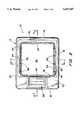
- FIG. 1is a front perspective view of the metal detector constructed in accordance with the present invention
- FIG. 2is a top plan with some parts in section, of the detector device illustrated in FIG. 1;
- FIG. 3is a cross-sectional view taken substantially along line 3--3 of FIG. 2;
- FIG. 4is cross-sectional view taken substantially along line 4--4 of FIG. 2 and illustrating placement of the device onto a receptacle support member;
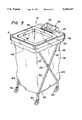
- FIG. 5is a side perspective view of the detector device constructed in accordance with present invention mounted onto a portable receptacle member;
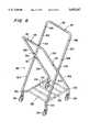
- FIG. 6is a side perspective view of the receptacle member illustrated in FIG. 5 without the receptacle bag and the detector device mounted thereon;
- FIG. 7is schematic diagram illustrating the circuitry of the metal detector of the present invention.
- FIG. 8is schematic diagram illustrating the circuitry of the LED emission and reception portion of the metal detector the present invention.
- FIG. 9is a schematic diagram illustrating a bar graph display and associated driver circuitry for displaying detector signal strength and battery voltage of the metal detector of the present invention.
- a metal detector device 10includes a housing 12 having a front portion 14, a rear portion 16 and two side portions 18 and 20, all of which are interconnected by a top surface 22.
- the housing 12is substantially rectangular in shape and includes an exterior circumferential lip 24 that depends downwardly from the top surface 22 along the front and rear portions 14, 16 and the side portions 18, 20.
- the lip 24provides a surface for mounting the housing 12 to a receptacle structure 26 which is designed to hold a waste disposal bag 28 as further described below.
- the housing 12is preferably constructed from any type of known non-metallic material and is most preferably constructed from molded plastic.
- the housing 12is formed as an integral component in a rotational molding process wherein a powdered plastic resin material gradually melts within a heated, rotating mold. The liquefied resin then coats the interior surfaces of the mold to form the housing 12. After cooling, the housing 12 is then removed from the mold.
- the moldis preferably configured to produce two component parts simultaneously which are severed after removal from the mold.
- a preferred plastic resin materialis polypropylene, although a wide variety of other plastics or non-ferrous materials may also be employed.
- the housing 12preferably includes a central aperture 30 which in preferred form is substantially square in shape.
- a plurality of inclined surfaces 32, 34, 36 and 38depend angularly downwardly from the top surface 22 toward the aperture 30 and terminate at the respective edges 40, 42, 44 and 46.
- a plurality of flanges 48, 50, 52 and 54each extend vertically downwardly from their respective side edges 40, 42, 44 and 46 to form a substantially square tube portion 55 defining the aperture 30.
- the aperture 30overlies and communicates with a top opening of a waste disposal bag 28. Accordingly, the inclined surfaces 32-38, the tube 55 and the aperture 30 facilitate the deposit of articles and material into the disposal bag 28 carried by the receptacle 26.
- a pair of pivot arms 56are preferably secured to the side edges 18, 20 of the housing 12 by a pair of mounting pins 58 in order to secure the housing 12 to the receptacle 26 in a hinged manner as described in greater detail below. In this manner, the housing 12 may be pivoted away from the disposal bag 28 in order to remove the disposal bag 28 from the receptacle 26 when it is full.
- a control console 60extends upwardly from a rear portion of the top 22 of housing 12 and preferably includes a downwardly and forwardly inclined control panel 62 surrounded by side members 64, 66. As particularly illustrated in FIG. 4, a hollow interior control box 68 is disposed within the interior of the console 60 and forms a housing for the electronic components of the metal detector 10 as described in greater detail below.
- the control panel 62preferably includes a peak-hold type LCD bar graph 70 for displaying voltage levels induced in the detection circuitry by the deposit of metal articles through the aperture 30 of the housing 12 in order to allow an operator to estimate the size of the metal article disposed.
- a peak-hold type LCD bar graph 70for displaying voltage levels induced in the detection circuitry by the deposit of metal articles through the aperture 30 of the housing 12 in order to allow an operator to estimate the size of the metal article disposed.
- an insignificant metal objectsuch as a surgical staple or the like would provide a low signal level and would not set off the alarm as described in greater detail below, while a large and expensive surgical instrument would provide a high signal level and set off the alarm.
- the peak-hold featurecauses the graph 70 to maintain the display for a time sufficient to enable operator inspection.
- a similar LCD bar graph 72provides an indication of battery voltage to allow an operator to estimate the remaining battery life for the unit 10.
- an LED low battery indicator 74provides a positive indication of the need to recharge the batteries for the detector 10.
- the metal detector 10is designed for ease of operation with minimal training.
- user friendly controlspreferably comprise three buttons including a reset button 76, an "on” button 78 and an “off” button 80.
- the reset button 76is designed to silence an audible alarm after detection of a metal article and to reset the metal detector for continued use.
- the "on” button 78activates the power to the device 10 while the "off” button 80 deactivates the power source.
- the control panel 62is preferably of a flexible membrane type commonly employed in microwave ovens in which the control buttons 76, 78 and 80 comprise zones designated by indicia which do not protrude above the panel 62.
- the LCD bar graph displays 70 and 72 and the LED light 74underlie the panel 62 and are displayed through transparent windows. Panels of this type are custom fabricated pursuant to customer specification by any number of vendors, and are well known to the art.
- an induction member in the form of a detection coil 82surrounds the aperture 30 and is designed to detect the presence of metal proximate thereto particularly as it passes through the aperture 30.
- the detection coil 82is preferably mounted to the outside surfaces 84 of the tube portion 55 which defines the aperture 30.
- the detection coil 82is mounted proximate to the lowermost edges of the flanges 48-54 and is secured in any manner thereto.
- a notch(not illustrated) may be formed in the surfaces 84 in which a coil member 82 may be wound.
- the detection coil 82includes a primary coil which is 26 gauge copper wire wound sixteen turns about the aperture 30 and a secondary coil which is also 26 gauge copper wire wound six rams about the aperture 30. In this manner, when a metal object moves physically near the detection coil 82, it causes a change in the electromagnetic field surrounding the coil 82, and this causes a change in the current described below. This is true, however, whether the metal article is proximate the coil 82 by being placed through the aperture 30 or proximate the coil 82 by being placed against, on top or even nearby the housing 12.
- a mechanism for sensing an object, metallic or otherwise, physically passing through the aperture 30is disposed about the aperture 30.
- this mechanismincludes a plurality of pulse emitting members 86 which preferably are in the form of light emitting diodes (LED's), and a plurality of pulse detecting members 88 preferably in the form of infrared phototransistors. While the preferred form of the members 86, 88 include infrared LED's and infrared phototransistors, ultrasound emitters and detectors may also be utilized.
- pulse emitting members 86there are sufficient numbers of pulse emitting members 86 disposed along one flange 50 and sufficient numbers of pulse detection members 88 disposed along the opposite flange 54 in order to span the entire cross-sectional area of the aperture 30.
- the pulse emitting members 86are preferably positioned proximate the edge 42 away from the coil 82 to minimize electrical interferences and are interconnected to the electronic components of the console 60 by wiring 90.
- the pulse detecting members 88are positioned proximate the edge 46 away from the coil 82 and are connected to the console 60 by wiring 92.
- pulse emitting members 86 and pulse detecting members 88aligned opposite each other so that as an object passes through the aperture 30, it physically interferes with the detection by at least one member 88 of a pulse being emitted from the members 86, and this interference is monitored by the members 88 and signaled to the control panel 60 in a manner described below.
- a rechargeable nickel-cadmium or nickel metal hydride battery 94provides all operating power for the detection circuitry of the device 10.
- a jack 96extends through the rear portion 16 and allows connection of the battery 94 to a conventional recharging device in a conventional manner.
- the device 10 of the present inventionoperates by powering the detection coil 82 so as to create a magnetic field surrounding it. If a metal member passes proximate to the detection coil 82, a change is detected in the electromagnetic field therein.
- a mechanismcalibrates the detection coil 82 by comparing the output voltage thereof caused by a change in the electromagnetic field thereabout to a reference voltage to establish a threshold voltage which is unaffected by transient fluctuations in the coil output voltage as described below. When the threshold voltage of the detection coil 82 is exceeded, an electric signal is generated to simultaneously activate the pulse emitting members 86.
- the pulse emitting members 86are only activated or turned on when the threshold voltage of the coil 82 is surpassed, non-metallic objects can consistently pass through the aperture 30 without generating an alarm signal since the pulse emitting members 86 are in a nonactive state. Consequently, the combination of the detection coil 82, the pulse emitting members 86 and the pulse detection members 88 and the circuitry interconnecting the same prevents false signals caused by metallic objects exterior to but proximate the detector 10 from being generated.
- a typical cart or receptacle structure 26is illustrated for holding a waste disposal bag 28 for use in conjunction with the metal detector 10. It should be understood, however, that the metal detector 10 of the present invention may be utilized with any type of receptacle and may be modified to fit the desired end use whether it be in a hospital environment, a penal institution, a kitchen environment or the like.
- the receptacle 26typically includes four tubular lower leg members 100, 102, 104 and 106 that are pivotally connected together in pairs by pivotal connection members 108 and 110.
- the pivotal connection members 108, 110may include rivets, pins, bolts, screws or any other appropriate member pivotally interconnecting legs 100 to 102 and 104 to 106.
- the upper portions of the receptacle 26include a pair of substantially U-shaped members 112, 114 secured to the upper portion of legs 100, 104 and 102, 106, respectively.
- each U-shaped portion 112, 114includes, respectively, a substantially transverse crossbar member 116, 118 extending between respective side frame bars 120, 122 and 124, 126.
- Interengaging telescoping connections 128, 130, 132 and 134removably connect the side frame bars 120, 122, 124 and 126 to their respective lower leg members 100, 104, 102 and 106, respectively.
- the upper U-shaped portions 112, 114are formed from a non-metallic material such as PVC plastic tubing in order to minimize interference with the metal detector's circuitry.
- the lower components of the receptacle 26may be formed from a lightweight tubular metal material such as aluminum tubing.
- a bag support rack 128includes four corner portions pivotally connected at 130 to lower end portions of the leg members 100, 102, 104 and 106.
- the rack 128has a two-piece construction, with side rail members bifurcated at abutting joints 132. Accordingly, the two rack halves may be folded upwardly for storage and transportation of the receptacle 26.
- leg members 100, 102, 104 and 106terminate in respective casters 134, 136, 138 and 140 which allow the receptacle 26 to be easily rolled to a desired location for use.
- a medical waste disposal bag 28is placed on the rack 128 with the upper side portions 142 of the bag 28 folded outwardly over the crossbars 116, 118 to maintain the mouth of the bag 28 in an open condition for access by the aperture 30 of the device 10.
- the housing 12is pivotally connected to the receptacle 26.
- a hinge member 56 in the form of an aluminum struthas a first end pivotally secured by a fastener 58 to the side portion 18 of the housing 12.
- a second fastener 144secures an opposite end of the pivot strut 56 to the aperture 146 in the upper portions of the side frame members 120.
- Fasteners 58 and 144may take the form of bolts, screws, rivets or pins. It should be understood that identical pivotal struts and fastener assemblies 56 are secured on both sides of the housing 12 and attach both side portions 18, 20 of the housing 12 to the tubes 120, 122 of the receptacle 26.
- the entire housing 12may thus be pivoted along an arc between a closed position as illustrated in FIG. 5 wherein the housing 12 is securely fixed about the transverse crossbars 116 and 118 of the receptacle 26 and the aperture 30 opens directly to the open end of the bag 28, and an open position.
- the open positionis illustrated in the cross-referenced parent patent application and is designed to rotate the front end member 14 away from engagement with the transverse crossbar 118 and rotate the housing 12 greater than 90° so as to gain full access to the open end of the bag 28 without passing through the aperture 30 or in any manner being hindered by the device 10.
- the housing 12 and the receptacle 26are preferably complementary dimensions such that the crossbars 116, 118 of the receptacle 26 nest within the housing 12 at the rear 16 and front-end portions 14, respectively.
- a jack 96allows connection of the battery 94 to a conventional recharging device in a conventional manner.
- a latching relay K1 controlled by the "on” push button 78 and the “off” push button 80provides for connection and disconnection of the battery 94 to the electronic detection circuitry.
- the voltage regulator 200reduces the battery voltage V+ to a reduced regulated voltage VCC.
- the detection circuitryincludes a primary coil 202 through which the current initially flows.
- the conduction of the transistor 204, resistor 206 and variable resistor 208control the current through the primary coil 202.
- the momentary current through the primary coil 202induces a voltage in the secondary coil of the detector coil 82 which controls the conduction of the transistor 204 which in turn again pulses current through the primary coil 202.
- the frequency of the oscillationsis determined by the parallel resonant frequency of the primary coil 202 and the capacitor 210.
- the voltage of the detector coil 82also controls the conduction of a transistor 212 which generates a DC voltage through resistor 214 and capacitor 216 which is directly proportional to the induced voltage in the detector cot 82.
- the detector circuitryfurther includes an auto calibration feature which prevents drift and maintains the accuracy of the detector over time while preventing environmental fluctuations therein from impairing detector performance.
- An amplifier 218compares the DC voltage from the transistor 212 (pin 7) with a reference voltage set up by resisters 220 and 222. The amplifier output swings high or low and is integrated through resistor 224 and capacitor 226. The output then conducts through the resistor 228 back to the transistor 204, which influences the amount of current pulsed through the primary coil 202. The action of this network maintains the DC voltage at transistor 212 to match the reference voltage at the amplifier 218. Since fluctuations are integrated over time, the network does not react to environmental changes but only to long term changes, and thus serves to stabilize the sensitivity of the metal detector 10.
- the metal detector 10includes an audio alarm 230 as well as the LCD bar graph visual display 260 to alert an operator of the passage of a significant metal object through the aperture 30 by the detector coil 82.
- a threshold detector 232includes a variable resistor 234 and amplifier 236 and compares the voltage induced in the detector coil 82 with a threshold reference voltage established by the resistor 234. If the detector coil voltage exceeds the threshold reference voltage, the amplifier 236 generates a trigger signal 238.
- the variable resistor 234may be set to vary the threshold voltage to permit the passage of small metal objects, such as staples or foil, through the aperture 30 without generating trigger signal 238.
- the preferred pulse generation membersare in the form of four infrared LED's 86 which are connected in series and are pulsed simultaneously by the trigger signal 238.
- the pulse receiving members 88are preferably in the form of infrared phototransistors.
- Amplifiers 240, 242, 244 and 246read the voltage outputs of the four phototransistors 88. So long as all four phototransistors 88 are activated by the reception of light emitted by the four LED's 86, nothing happens. However, if one of the amplifiers 240-246 does not register a voltage output by its corresponding phototransistor 88 while the remaining amplifiers do so register output by the remaining phototransistors 88, then an alarm signal 248 is generated since the light from one of the LED's 86 has been blocked from reception by a phototransistor 88 due to the physical presence of an object in the aperture 30.
- a latch 250is set and activates the audio alarm 230.
- the external reset button 76 for the latch 250shuts off the alarm.
- an additional signal 252is generated and is directed to a real time voltage circuit 254 which processes the voltage induced in the detector coil 82 and outputs the voltage to the analog input of a bar graph driver 256.
- the bar graph driver 256displays the real time voltage on one portion 70 of a dual bar graph LCD display 260.
- a second bar graph driver 258displays the battery voltage V+ on the other portion 72 of the LCD display 260 and also pulses the low battery LED 74 if the battery voltage V+ falls below a predetermined limit.
- the present inventionprovides for a portable metal detector unit that is useful in a wide variety of environments including hospital surgery rooms, prisons, kitchens or high security areas to prevent the inadvertent disposal or the intentional hiding of metal objects in receptacles.
- the device of the present inventionis removably attachable to a wide variety of types of receptacles and can be moved out of the way in order to easily replace receptacle bags.
- the present inventionis portable and may therefore come into the physical presence of large metal objects exterior to the device, the present invention is designed to prevent inadvertent triggering of the alarm system by the presence of such metal objects outside of the aperture of the device.
- the present inventionprevents the inadvertent loss of expensive surgical instruments or kitchen utensils thus providing substantial savings to hospitals, restaurants and the like. Moreover, the present invention prevents the smuggling of metal objects from one room to another by their placement in a receptacle. Nonetheless, people utilizing the device of the invention are not hampered by improper signals due to the passage of very small metal objects through the aperture or the presence of metal objects immediately outside the device due to its built in safeguard system.
Landscapes
- Life Sciences & Earth Sciences (AREA)
- Engineering & Computer Science (AREA)
- Health & Medical Sciences (AREA)
- Surgery (AREA)
- Remote Sensing (AREA)
- Biomedical Technology (AREA)
- Physics & Mathematics (AREA)
- General Life Sciences & Earth Sciences (AREA)
- General Physics & Mathematics (AREA)
- Geophysics (AREA)
- Environmental & Geological Engineering (AREA)
- Nuclear Medicine, Radiotherapy & Molecular Imaging (AREA)
- Mechanical Engineering (AREA)
- Geology (AREA)
- Heart & Thoracic Surgery (AREA)
- Medical Informatics (AREA)
- Molecular Biology (AREA)
- Animal Behavior & Ethology (AREA)
- General Health & Medical Sciences (AREA)
- Public Health (AREA)
- Veterinary Medicine (AREA)
- Geophysics And Detection Of Objects (AREA)
Abstract
Description
Claims (25)
Priority Applications (1)
| Application Number | Priority Date | Filing Date | Title |
|---|---|---|---|
| US08/570,348US5659247A (en) | 1994-03-10 | 1995-12-11 | Device for detecting metal objects passing through an opening |
Applications Claiming Priority (2)
| Application Number | Priority Date | Filing Date | Title |
|---|---|---|---|
| US08/209,394US5576621A (en) | 1994-03-10 | 1994-03-10 | Hinged metal detection cover for a receptacle |
| US08/570,348US5659247A (en) | 1994-03-10 | 1995-12-11 | Device for detecting metal objects passing through an opening |
Related Parent Applications (1)
| Application Number | Title | Priority Date | Filing Date |
|---|---|---|---|
| US08/209,394Continuation-In-PartUS5576621A (en) | 1994-03-10 | 1994-03-10 | Hinged metal detection cover for a receptacle |
Publications (1)
| Publication Number | Publication Date |
|---|---|
| US5659247Atrue US5659247A (en) | 1997-08-19 |
Family
ID=46250859
Family Applications (1)
| Application Number | Title | Priority Date | Filing Date |
|---|---|---|---|
| US08/570,348Expired - Fee RelatedUS5659247A (en) | 1994-03-10 | 1995-12-11 | Device for detecting metal objects passing through an opening |
Country Status (1)
| Country | Link |
|---|---|
| US (1) | US5659247A (en) |
Cited By (55)
| Publication number | Priority date | Publication date | Assignee | Title |
|---|---|---|---|---|
| US6222450B1 (en)* | 2000-02-02 | 2001-04-24 | Denver Dynamics, Inc. | Metal detection device having improved support assembly |
| US20020158068A1 (en)* | 2001-04-30 | 2002-10-31 | Panek Robert Joseph | Medical waste disposal system |
| USD478701S1 (en) | 2001-04-30 | 2003-08-19 | Tyco Healthcare Group Lp | Cart body for a medical waste disposal system |
| US20040000904A1 (en)* | 2002-06-28 | 2004-01-01 | Cotter James E. | Apparatus for detecting metal objects being put into a trash can |
| US6822171B2 (en)* | 2000-05-26 | 2004-11-23 | Ishida Co., Ltd. | Article handling system |
| US6833789B1 (en)* | 2001-09-24 | 2004-12-21 | Billy W. Carmen | Utensil metal detector |
| WO2005088347A1 (en)* | 2004-03-09 | 2005-09-22 | Robert Bosch Gmbh | Locating device |
| USD535453S1 (en) | 2005-09-23 | 2007-01-16 | Sherwood Services Ag | Phlebotomy cart |
| US20070069490A1 (en)* | 2005-09-23 | 2007-03-29 | John Japuntich | Sharps container configured for cart mounting |
| US20070068942A1 (en)* | 2005-09-26 | 2007-03-29 | Smudde Anton M | Multiple container cart with individual foot pedal/lid actuation |
| USD542999S1 (en) | 2005-07-15 | 2007-05-15 | Sherwood Services Ag | Cart body for a medical waste disposal system |
| US20070204888A1 (en)* | 2006-03-02 | 2007-09-06 | Miller Kenneth M | Apparatus and method for retaining discarded flatware |
| USD551345S1 (en) | 2005-09-14 | 2007-09-18 | Sherwood Services Ag | Sharps container configured for cart mounting |
| US7296683B1 (en)* | 2002-05-22 | 2007-11-20 | Vallelonga Sr Kenneth M | Ferrous metal detector with alarm |
| US20090145901A1 (en)* | 2001-04-30 | 2009-06-11 | Cavidien Ag | Medical Waste Disposal System |
| WO2009155107A2 (en) | 2008-05-30 | 2009-12-23 | Stryker Corporation | Waste collection system for collecting solid medical waste including metal detection, pre-detection apparatus, and/or bag-tensioning mechanism |
| US20100201090A1 (en)* | 2007-10-18 | 2010-08-12 | Bruce Henniges | System and method for compacting solid medical waste |
| ITRM20090110A1 (en)* | 2009-03-11 | 2010-09-12 | Fabio Giordani | DEVICE FOR DETECTION AND SIGNALING OF METALLIC OBJECTS INSIDE A WASTE CONTAINER. |
| US20110239794A1 (en)* | 2008-10-27 | 2011-10-06 | Robert Bosch Gmbh | Locating Device |
| CN1930493B (en)* | 2004-03-12 | 2012-06-13 | 罗伯特·博世有限公司 | Locating device |
| US20120159206A1 (en)* | 2010-12-20 | 2012-06-21 | Sony Corporation | Information processor |
| US20130248395A1 (en)* | 2012-03-22 | 2013-09-26 | Guardianor | Medical waste system |
| USD699400S1 (en)* | 2013-03-24 | 2014-02-11 | Keter Plastic Ltd. | Animal feeder |
| WO2014144738A1 (en)* | 2013-03-15 | 2014-09-18 | Proteus Digital Health, Inc. | Metal detector apparatus, system, and method |
| US9268909B2 (en) | 2012-10-18 | 2016-02-23 | Proteus Digital Health, Inc. | Apparatus, system, and method to adaptively optimize power dissipation and broadcast power in a power source for a communication device |
| US9271897B2 (en) | 2012-07-23 | 2016-03-01 | Proteus Digital Health, Inc. | Techniques for manufacturing ingestible event markers comprising an ingestible component |
| US9320455B2 (en) | 2009-04-28 | 2016-04-26 | Proteus Digital Health, Inc. | Highly reliable ingestible event markers and methods for using the same |
| US9415010B2 (en) | 2008-08-13 | 2016-08-16 | Proteus Digital Health, Inc. | Ingestible circuitry |
| US9439582B2 (en) | 2005-04-28 | 2016-09-13 | Proteus Digital Health, Inc. | Communication system with remote activation |
| CN106043994A (en)* | 2016-05-24 | 2016-10-26 | 江苏腾飞环境工程设备有限公司 | Solar energy environment-friendly cleaning box |
| WO2017023835A1 (en)* | 2015-07-31 | 2017-02-09 | Enventys, Llc | Waste receptacle |
| US9597487B2 (en) | 2010-04-07 | 2017-03-21 | Proteus Digital Health, Inc. | Miniature ingestible device |
| US9649066B2 (en) | 2005-04-28 | 2017-05-16 | Proteus Digital Health, Inc. | Communication system with partial power source |
| US20170183151A1 (en)* | 2015-07-31 | 2017-06-29 | Edison Nation Medical, Llc | Waste receptacle |
| WO2017112870A1 (en)* | 2015-12-23 | 2017-06-29 | Stryker Corporation | Metal detection system for use with medical waste container |
| US9756874B2 (en) | 2011-07-11 | 2017-09-12 | Proteus Digital Health, Inc. | Masticable ingestible product and communication system therefor |
| US9796576B2 (en) | 2013-08-30 | 2017-10-24 | Proteus Digital Health, Inc. | Container with electronically controlled interlock |
| AU2015224494B2 (en)* | 2008-05-30 | 2017-12-14 | Stryker Corporation | Portable cart for containing medical waste that includes a bag tensioner |
| US9962107B2 (en) | 2005-04-28 | 2018-05-08 | Proteus Digital Health, Inc. | Communication system with enhanced partial power source and method of manufacturing same |
| US10084880B2 (en) | 2013-11-04 | 2018-09-25 | Proteus Digital Health, Inc. | Social media networking based on physiologic information |
| US20190006047A1 (en)* | 2015-10-29 | 2019-01-03 | Sharp Fluidics Llc | Systems and methods for data capture in an operating room |
| US10187121B2 (en) | 2016-07-22 | 2019-01-22 | Proteus Digital Health, Inc. | Electromagnetic sensing and detection of ingestible event markers |
| US10321968B2 (en) | 2015-10-23 | 2019-06-18 | Medline Industries, Inc. | Sharps container |
| US10398161B2 (en) | 2014-01-21 | 2019-09-03 | Proteus Digital Heal Th, Inc. | Masticable ingestible product and communication system therefor |
| FR3092188A1 (en)* | 2019-01-30 | 2020-07-31 | Alessandro Manneschi | Luggage detector |
| FR3092187A1 (en)* | 2019-01-30 | 2020-07-31 | Alessandro Manneschi | Luggage detector |
| CN111629981A (en)* | 2018-01-24 | 2020-09-04 | 鹰野株式会社 | Medical waste container, rack for medical waste container, and medical waste detection system |
| US11051543B2 (en) | 2015-07-21 | 2021-07-06 | Otsuka Pharmaceutical Co. Ltd. | Alginate on adhesive bilayer laminate film |
| US11149123B2 (en) | 2013-01-29 | 2021-10-19 | Otsuka Pharmaceutical Co., Ltd. | Highly-swellable polymeric films and compositions comprising the same |
| US11402535B1 (en) | 2017-01-31 | 2022-08-02 | Diteqt Llc | Waste receptacle configured to differentiate items |
| US11504511B2 (en) | 2010-11-22 | 2022-11-22 | Otsuka Pharmaceutical Co., Ltd. | Ingestible device with pharmaceutical product |
| US11529071B2 (en) | 2016-10-26 | 2022-12-20 | Otsuka Pharmaceutical Co., Ltd. | Methods for manufacturing capsules with ingestible event markers |
| CN115772774A (en)* | 2021-09-09 | 2023-03-10 | 青岛海尔洗涤电器有限公司 | Clothes processing device and control method thereof |
| CN116145384A (en)* | 2021-11-19 | 2023-05-23 | 青岛海尔洗衣机有限公司 | Clothes processing equipment and metal foreign object detection method |
| US12359367B1 (en)* | 2024-10-29 | 2025-07-15 | Shenzhen Yi Hong Holding Group Co., Ltd. | Storage basket structure and laundry basket |
Citations (4)
| Publication number | Priority date | Publication date | Assignee | Title |
|---|---|---|---|---|
| US4593184A (en)* | 1983-08-19 | 1986-06-03 | Brandt, Incorporated | Counterfeit detection circuit |
| US4949037A (en)* | 1987-08-25 | 1990-08-14 | Anritsu Corporation | System for detecting metal in articles using phase change of detection signals |
| US5001425A (en)* | 1989-12-13 | 1991-03-19 | Winfield Corporation | Ferromagnetic object detector with comparison of signal maximums from a pair of detection coils |
| US5406259A (en)* | 1992-11-19 | 1995-04-11 | C.E.I.A. - Costruzioni Elettroniche Industriali Automatismi - S.P.A. | High uniformity metal detector equipped with auxiliary receiver coils sensitive to metal masses passing close to them |
- 1995
- 1995-12-11USUS08/570,348patent/US5659247A/ennot_activeExpired - Fee Related
Patent Citations (4)
| Publication number | Priority date | Publication date | Assignee | Title |
|---|---|---|---|---|
| US4593184A (en)* | 1983-08-19 | 1986-06-03 | Brandt, Incorporated | Counterfeit detection circuit |
| US4949037A (en)* | 1987-08-25 | 1990-08-14 | Anritsu Corporation | System for detecting metal in articles using phase change of detection signals |
| US5001425A (en)* | 1989-12-13 | 1991-03-19 | Winfield Corporation | Ferromagnetic object detector with comparison of signal maximums from a pair of detection coils |
| US5406259A (en)* | 1992-11-19 | 1995-04-11 | C.E.I.A. - Costruzioni Elettroniche Industriali Automatismi - S.P.A. | High uniformity metal detector equipped with auxiliary receiver coils sensitive to metal masses passing close to them |
Cited By (125)
| Publication number | Priority date | Publication date | Assignee | Title |
|---|---|---|---|---|
| AU770740B2 (en)* | 2000-02-02 | 2004-03-04 | Denver Dynamics, Inc. | Metal detection device having improved support assembly |
| WO2001057820A1 (en)* | 2000-02-02 | 2001-08-09 | Denver Dynamics, Inc. | Metal detection device having improved support assembly |
| US6222450B1 (en)* | 2000-02-02 | 2001-04-24 | Denver Dynamics, Inc. | Metal detection device having improved support assembly |
| US6822171B2 (en)* | 2000-05-26 | 2004-11-23 | Ishida Co., Ltd. | Article handling system |
| US8695834B2 (en) | 2001-04-30 | 2014-04-15 | Covidien Lp | Medical waste disposal container system |
| US7114629B2 (en)* | 2001-04-30 | 2006-10-03 | Tyco Healthcare Group Lp | Medical waste disposal system |
| US20080156666A1 (en)* | 2001-04-30 | 2008-07-03 | Tyco Healthcare Group Lp | Medical Waste Disposal System |
| US20040222335A1 (en)* | 2001-04-30 | 2004-11-11 | Panek Robert Joseph | Medical waste disposal system |
| USD478701S1 (en) | 2001-04-30 | 2003-08-19 | Tyco Healthcare Group Lp | Cart body for a medical waste disposal system |
| US20080156818A1 (en)* | 2001-04-30 | 2008-07-03 | Tyco Healthcare Group Lp | Medical Waste Disposal Container System |
| US7364049B2 (en) | 2001-04-30 | 2008-04-29 | Covidien Ag | Medical waste disposal system |
| US20090145901A1 (en)* | 2001-04-30 | 2009-06-11 | Cavidien Ag | Medical Waste Disposal System |
| US8613366B2 (en) | 2001-04-30 | 2013-12-24 | Covidien Lp | Medical waste disposal system |
| US8201704B2 (en) | 2001-04-30 | 2012-06-19 | Brian Finnestad | Medical waste disposal system |
| US20020158068A1 (en)* | 2001-04-30 | 2002-10-31 | Panek Robert Joseph | Medical waste disposal system |
| US7784167B2 (en) | 2001-04-30 | 2010-08-31 | Tyco Healthcare Group Lp | Method of forming a medical waste disposal system |
| US6833789B1 (en)* | 2001-09-24 | 2004-12-21 | Billy W. Carmen | Utensil metal detector |
| US7296683B1 (en)* | 2002-05-22 | 2007-11-20 | Vallelonga Sr Kenneth M | Ferrous metal detector with alarm |
| US20040000904A1 (en)* | 2002-06-28 | 2004-01-01 | Cotter James E. | Apparatus for detecting metal objects being put into a trash can |
| EP1378768A3 (en)* | 2002-06-28 | 2004-04-14 | James E. Cotter | Apparatus for detecting metal objects being put into a trash can |
| WO2005088347A1 (en)* | 2004-03-09 | 2005-09-22 | Robert Bosch Gmbh | Locating device |
| US20070188158A1 (en)* | 2004-03-09 | 2007-08-16 | Uwe Skultety-Betz | Locating device |
| US7940048B2 (en) | 2004-03-09 | 2011-05-10 | Robert Bosch Gmbh | Locating device |
| CN1930492B (en)* | 2004-03-09 | 2012-06-13 | 罗伯特·博世有限公司 | Locating device |
| CN1930493B (en)* | 2004-03-12 | 2012-06-13 | 罗伯特·博世有限公司 | Locating device |
| US11476952B2 (en) | 2005-04-28 | 2022-10-18 | Otsuka Pharmaceutical Co., Ltd. | Pharma-informatics system |
| US9962107B2 (en) | 2005-04-28 | 2018-05-08 | Proteus Digital Health, Inc. | Communication system with enhanced partial power source and method of manufacturing same |
| US9439582B2 (en) | 2005-04-28 | 2016-09-13 | Proteus Digital Health, Inc. | Communication system with remote activation |
| US9649066B2 (en) | 2005-04-28 | 2017-05-16 | Proteus Digital Health, Inc. | Communication system with partial power source |
| US10517507B2 (en) | 2005-04-28 | 2019-12-31 | Proteus Digital Health, Inc. | Communication system with enhanced partial power source and method of manufacturing same |
| US10542909B2 (en) | 2005-04-28 | 2020-01-28 | Proteus Digital Health, Inc. | Communication system with partial power source |
| US9681842B2 (en) | 2005-04-28 | 2017-06-20 | Proteus Digital Health, Inc. | Pharma-informatics system |
| US10610128B2 (en) | 2005-04-28 | 2020-04-07 | Proteus Digital Health, Inc. | Pharma-informatics system |
| USD542999S1 (en) | 2005-07-15 | 2007-05-15 | Sherwood Services Ag | Cart body for a medical waste disposal system |
| USD551345S1 (en) | 2005-09-14 | 2007-09-18 | Sherwood Services Ag | Sharps container configured for cart mounting |
| US20070069490A1 (en)* | 2005-09-23 | 2007-03-29 | John Japuntich | Sharps container configured for cart mounting |
| USD535453S1 (en) | 2005-09-23 | 2007-01-16 | Sherwood Services Ag | Phlebotomy cart |
| US20070068942A1 (en)* | 2005-09-26 | 2007-03-29 | Smudde Anton M | Multiple container cart with individual foot pedal/lid actuation |
| US7878358B2 (en) | 2005-09-26 | 2011-02-01 | Covidien Ag | Multiple container cart with individual foot pedal/lid actuation |
| US20070204888A1 (en)* | 2006-03-02 | 2007-09-06 | Miller Kenneth M | Apparatus and method for retaining discarded flatware |
| US20100201090A1 (en)* | 2007-10-18 | 2010-08-12 | Bruce Henniges | System and method for compacting solid medical waste |
| AU2008312404B2 (en)* | 2007-10-18 | 2014-10-09 | Stryker Corporation | System and method for compacting medical waste |
| US8905413B2 (en) | 2007-10-18 | 2014-12-09 | Stryker Corporation | Method for compacting solid medical waste |
| US11676474B2 (en)* | 2008-05-30 | 2023-06-13 | Stryker Corporation | System and method for collecting medical waste that monitors the waste for objects that may have been inadvertently discarded |
| EP4140515A1 (en)* | 2008-05-30 | 2023-03-01 | Stryker Corporation | Portable cart for collecting medical waste |
| US9711033B2 (en) | 2008-05-30 | 2017-07-18 | Stryker Corporation | System and method for collecting medical waste that monitors the waste for objects that may have been inadvertantly discarded |
| AU2009260433B2 (en)* | 2008-05-30 | 2015-06-11 | Stryker Corporation | Portable Cart for Containing Medical Waste |
| US9089318B2 (en)* | 2008-05-30 | 2015-07-28 | Stryker Corporation | Waste collection system for collecting solid medical waste including a loading station with a metal detection sensor and/or a bag-tensioning mechanism |
| EP2291137A4 (en)* | 2008-05-30 | 2014-04-02 | Stryker Corp | WASTE COLLECTION SYSTEM FOR COLLECTING SOLID MEDICAL WASTE INCLUDING METAL DETECTION, METAL PRE-DETECTION APPARATUS, AND BAG TENSION MECHANISM |
| US20220051544A1 (en)* | 2008-05-30 | 2022-02-17 | Stryker Corporation | System And Method For Collecting Medical Waste That Monitors The Waste For Objects That May Have Been Inadvertently Discarded |
| US20180357882A1 (en)* | 2008-05-30 | 2018-12-13 | Stryker Corporation | System And Method For Collecting Medical Waste That Monitors The Waste For Objects That May Have Been Inadvertently Discarded |
| AU2015224494B2 (en)* | 2008-05-30 | 2017-12-14 | Stryker Corporation | Portable cart for containing medical waste that includes a bag tensioner |
| US20110156903A1 (en)* | 2008-05-30 | 2011-06-30 | Henniges Bruce D | Waste collection system for collecting solid medical waste including metal detection, pre-detection apparatus, and/or bag- tensioning mechanism |
| EP3372188A1 (en)* | 2008-05-30 | 2018-09-12 | Stryker Corporation | Waste collection system for collecting solid medical waste including metal detection |
| US11164440B2 (en)* | 2008-05-30 | 2021-11-02 | Stryker Corporation | System and method for collecting medical waste that monitors the waste for objects that may have been inadvertently discarded |
| WO2009155107A2 (en) | 2008-05-30 | 2009-12-23 | Stryker Corporation | Waste collection system for collecting solid medical waste including metal detection, pre-detection apparatus, and/or bag-tensioning mechanism |
| US10762763B2 (en)* | 2008-05-30 | 2020-09-01 | Stryker Corporation | System and method for collecting medical waste that monitors the waste for objects that may have been inadvertently discarded |
| US10083593B2 (en)* | 2008-05-30 | 2018-09-25 | Stryker Corporation | System and method for collecting medical waste that monitors the waste for objects that may have been inadvertantly discarded |
| US20170372587A1 (en)* | 2008-05-30 | 2017-12-28 | Stryker Corporation | System and method for collecting medic al waste that monitors the waste for objects that may have been inadvertantly discarded |
| EP3698818A1 (en)* | 2008-05-30 | 2020-08-26 | Stryker Corporation | Portable cart for containing medical waste |
| US9415010B2 (en) | 2008-08-13 | 2016-08-16 | Proteus Digital Health, Inc. | Ingestible circuitry |
| US20110239794A1 (en)* | 2008-10-27 | 2011-10-06 | Robert Bosch Gmbh | Locating Device |
| US8783123B2 (en)* | 2008-10-27 | 2014-07-22 | Robert Bosch Gmbh | Locating device |
| ITRM20090110A1 (en)* | 2009-03-11 | 2010-09-12 | Fabio Giordani | DEVICE FOR DETECTION AND SIGNALING OF METALLIC OBJECTS INSIDE A WASTE CONTAINER. |
| EP2228321A1 (en)* | 2009-03-11 | 2010-09-15 | Fabio Giordani | A device for detecting and signalling the presence of metal objects inside a refuse container |
| US10588544B2 (en) | 2009-04-28 | 2020-03-17 | Proteus Digital Health, Inc. | Highly reliable ingestible event markers and methods for using the same |
| US9320455B2 (en) | 2009-04-28 | 2016-04-26 | Proteus Digital Health, Inc. | Highly reliable ingestible event markers and methods for using the same |
| US10207093B2 (en) | 2010-04-07 | 2019-02-19 | Proteus Digital Health, Inc. | Miniature ingestible device |
| US9597487B2 (en) | 2010-04-07 | 2017-03-21 | Proteus Digital Health, Inc. | Miniature ingestible device |
| US11173290B2 (en) | 2010-04-07 | 2021-11-16 | Otsuka Pharmaceutical Co., Ltd. | Miniature ingestible device |
| US11504511B2 (en) | 2010-11-22 | 2022-11-22 | Otsuka Pharmaceutical Co., Ltd. | Ingestible device with pharmaceutical product |
| US20120159206A1 (en)* | 2010-12-20 | 2012-06-21 | Sony Corporation | Information processor |
| US9756874B2 (en) | 2011-07-11 | 2017-09-12 | Proteus Digital Health, Inc. | Masticable ingestible product and communication system therefor |
| US11229378B2 (en) | 2011-07-11 | 2022-01-25 | Otsuka Pharmaceutical Co., Ltd. | Communication system with enhanced partial power source and method of manufacturing same |
| US20130248395A1 (en)* | 2012-03-22 | 2013-09-26 | Guardianor | Medical waste system |
| US9271897B2 (en) | 2012-07-23 | 2016-03-01 | Proteus Digital Health, Inc. | Techniques for manufacturing ingestible event markers comprising an ingestible component |
| US9268909B2 (en) | 2012-10-18 | 2016-02-23 | Proteus Digital Health, Inc. | Apparatus, system, and method to adaptively optimize power dissipation and broadcast power in a power source for a communication device |
| US11149123B2 (en) | 2013-01-29 | 2021-10-19 | Otsuka Pharmaceutical Co., Ltd. | Highly-swellable polymeric films and compositions comprising the same |
| US10175376B2 (en) | 2013-03-15 | 2019-01-08 | Proteus Digital Health, Inc. | Metal detector apparatus, system, and method |
| WO2014144738A1 (en)* | 2013-03-15 | 2014-09-18 | Proteus Digital Health, Inc. | Metal detector apparatus, system, and method |
| USD699400S1 (en)* | 2013-03-24 | 2014-02-11 | Keter Plastic Ltd. | Animal feeder |
| US10421658B2 (en) | 2013-08-30 | 2019-09-24 | Proteus Digital Health, Inc. | Container with electronically controlled interlock |
| US9796576B2 (en) | 2013-08-30 | 2017-10-24 | Proteus Digital Health, Inc. | Container with electronically controlled interlock |
| US10084880B2 (en) | 2013-11-04 | 2018-09-25 | Proteus Digital Health, Inc. | Social media networking based on physiologic information |
| US10398161B2 (en) | 2014-01-21 | 2019-09-03 | Proteus Digital Heal Th, Inc. | Masticable ingestible product and communication system therefor |
| US11950615B2 (en) | 2014-01-21 | 2024-04-09 | Otsuka Pharmaceutical Co., Ltd. | Masticable ingestible product and communication system therefor |
| US11051543B2 (en) | 2015-07-21 | 2021-07-06 | Otsuka Pharmaceutical Co. Ltd. | Alginate on adhesive bilayer laminate film |
| US20220335808A1 (en)* | 2015-07-31 | 2022-10-20 | Michael Morgan Starkey | Waste receptacle |
| US11380188B2 (en)* | 2015-07-31 | 2022-07-05 | Diteqt, Llc | Waste receptacle |
| US11551538B2 (en)* | 2015-07-31 | 2023-01-10 | Diteqt, Llc | Waste receptacle |
| US20170183151A1 (en)* | 2015-07-31 | 2017-06-29 | Edison Nation Medical, Llc | Waste receptacle |
| US9637309B2 (en)* | 2015-07-31 | 2017-05-02 | Edison Nation Medical, Llc | Waste receptacle |
| US9842484B2 (en)* | 2015-07-31 | 2017-12-12 | Edison Nation Medical, Llc | Waste receptacle |
| US20230410632A1 (en)* | 2015-07-31 | 2023-12-21 | Diteqt, Llc | Waste receptacle |
| US9840369B2 (en)* | 2015-07-31 | 2017-12-12 | Edison Nation Medical, Llc | Waste receptacle |
| US20170183150A1 (en)* | 2015-07-31 | 2017-06-29 | Edison Nation Medical, Llc | Waste receptacle |
| WO2017023835A1 (en)* | 2015-07-31 | 2017-02-09 | Enventys, Llc | Waste receptacle |
| US10321968B2 (en) | 2015-10-23 | 2019-06-18 | Medline Industries, Inc. | Sharps container |
| US12082951B2 (en) | 2015-10-23 | 2024-09-10 | Medine Industries, LP | Sharps container |
| US11559369B2 (en) | 2015-10-23 | 2023-01-24 | Medline Industries, Lp | Sharps container |
| US20190006047A1 (en)* | 2015-10-29 | 2019-01-03 | Sharp Fluidics Llc | Systems and methods for data capture in an operating room |
| US11446109B2 (en) | 2015-12-23 | 2022-09-20 | Stryker Corporation | Metal detection system for use with medical waste container |
| US11000341B2 (en)* | 2015-12-23 | 2021-05-11 | Stryker Corporation | Metal detection system for use with medical waste container |
| US12089973B2 (en) | 2015-12-23 | 2024-09-17 | Stryker Corporation | Metal detection system for use with medical waste container |
| WO2017112870A1 (en)* | 2015-12-23 | 2017-06-29 | Stryker Corporation | Metal detection system for use with medical waste container |
| US20180368933A1 (en)* | 2015-12-23 | 2018-12-27 | Stryker Corporation | Metal Detection System For Use With Medical Waste Container |
| EP4218655A3 (en)* | 2015-12-23 | 2023-08-23 | Stryker Corporation | Metal detection system for use with medical waste container |
| CN106043994A (en)* | 2016-05-24 | 2016-10-26 | 江苏腾飞环境工程设备有限公司 | Solar energy environment-friendly cleaning box |
| US10797758B2 (en) | 2016-07-22 | 2020-10-06 | Proteus Digital Health, Inc. | Electromagnetic sensing and detection of ingestible event markers |
| US10187121B2 (en) | 2016-07-22 | 2019-01-22 | Proteus Digital Health, Inc. | Electromagnetic sensing and detection of ingestible event markers |
| US11529071B2 (en) | 2016-10-26 | 2022-12-20 | Otsuka Pharmaceutical Co., Ltd. | Methods for manufacturing capsules with ingestible event markers |
| US11793419B2 (en) | 2016-10-26 | 2023-10-24 | Otsuka Pharmaceutical Co., Ltd. | Methods for manufacturing capsules with ingestible event markers |
| US11402535B1 (en) | 2017-01-31 | 2022-08-02 | Diteqt Llc | Waste receptacle configured to differentiate items |
| CN111629981A (en)* | 2018-01-24 | 2020-09-04 | 鹰野株式会社 | Medical waste container, rack for medical waste container, and medical waste detection system |
| FR3092188A1 (en)* | 2019-01-30 | 2020-07-31 | Alessandro Manneschi | Luggage detector |
| US11906686B2 (en)* | 2019-01-30 | 2024-02-20 | Alessandro Manneschi | Luggage detector |
| US11947065B2 (en) | 2019-01-30 | 2024-04-02 | Alessandro Manneschi | System and method for detection of illicit objects in luggage |
| WO2020157145A1 (en) | 2019-01-30 | 2020-08-06 | Alessandro Manneschi | Luggage detector |
| WO2020157223A1 (en) | 2019-01-30 | 2020-08-06 | Alessandro Manneschi | Luggage detector |
| FR3092187A1 (en)* | 2019-01-30 | 2020-07-31 | Alessandro Manneschi | Luggage detector |
| WO2023036002A1 (en)* | 2021-09-09 | 2023-03-16 | 青岛海尔洗涤电器有限公司 | Laundry treatment apparatus and control method therefor |
| CN115772774A (en)* | 2021-09-09 | 2023-03-10 | 青岛海尔洗涤电器有限公司 | Clothes processing device and control method thereof |
| CN115772774B (en)* | 2021-09-09 | 2025-01-14 | 青岛海尔洗涤电器有限公司 | Clothes treatment device and control method thereof |
| CN116145384A (en)* | 2021-11-19 | 2023-05-23 | 青岛海尔洗衣机有限公司 | Clothes processing equipment and metal foreign object detection method |
| US12359367B1 (en)* | 2024-10-29 | 2025-07-15 | Shenzhen Yi Hong Holding Group Co., Ltd. | Storage basket structure and laundry basket |
Similar Documents
| Publication | Publication Date | Title |
|---|---|---|
| US5659247A (en) | Device for detecting metal objects passing through an opening | |
| US5576621A (en) | Hinged metal detection cover for a receptacle | |
| US6222450B1 (en) | Metal detection device having improved support assembly | |
| US11551538B2 (en) | Waste receptacle | |
| US10815053B2 (en) | Waste receptacle | |
| US11164440B2 (en) | System and method for collecting medical waste that monitors the waste for objects that may have been inadvertently discarded | |
| US4325058A (en) | Pre-intrusion detection and alarm system | |
| EP1563326B1 (en) | Ferromagnetic object detector | |
| US20040000904A1 (en) | Apparatus for detecting metal objects being put into a trash can | |
| EP2761607B1 (en) | Detection device | |
| US6833789B1 (en) | Utensil metal detector | |
| US5705986A (en) | Method of and apparatus for automatic deactivation of electronic article surveillance tags | |
| KR200251292Y1 (en) | A Burglarproof Cover | |
| AU722543C (en) | Method of and apparatus for automatic deactivation of electronic article surveillance tags | |
| JPH11251085A (en) | Safekeeping device equipped with charged state displaying means for magnetically recorded article or the like |
Legal Events
| Date | Code | Title | Description |
|---|---|---|---|
| AS | Assignment | Owner name:DENVER DYNAMICS, INC., COLORADO Free format text:ASSIGNMENT OF ASSIGNORS INTEREST;ASSIGNOR:CLEMENTS, PHILIP E.;REEL/FRAME:008351/0188 Effective date:19951129 | |
| AS | Assignment | Owner name:DENVER DYNAMICS, INC., A COLORADO CORPORATION, COL Free format text:ASSIGNMENT OF ASSIGNORS INTEREST;ASSIGNOR:DENVER DYNAMICS, INC. A DISSOLVED COLORADO CORPORATION;REEL/FRAME:010121/0208 Effective date:19990210 | |
| AS | Assignment | Owner name:BLESSMAN, LYLE L., COLORADO Free format text:SECURITY INTEREST;ASSIGNOR:DENVER DYNAMICS, INC.;REEL/FRAME:010197/0122 Effective date:19950303 | |
| FPAY | Fee payment | Year of fee payment:4 | |
| REMI | Maintenance fee reminder mailed | ||
| LAPS | Lapse for failure to pay maintenance fees | ||
| LAPS | Lapse for failure to pay maintenance fees | Free format text:PATENT EXPIRED FOR FAILURE TO PAY MAINTENANCE FEES (ORIGINAL EVENT CODE: EXP.); ENTITY STATUS OF PATENT OWNER: SMALL ENTITY | |
| STCH | Information on status: patent discontinuation | Free format text:PATENT EXPIRED DUE TO NONPAYMENT OF MAINTENANCE FEES UNDER 37 CFR 1.362 | |
| FP | Lapsed due to failure to pay maintenance fee | Effective date:20050819 |