US5659240A - Intelligent battery charger for electric drive system batteries - Google Patents
Intelligent battery charger for electric drive system batteriesDownload PDFInfo
- Publication number
- US5659240A US5659240AUS08/390,205US39020595AUS5659240AUS 5659240 AUS5659240 AUS 5659240AUS 39020595 AUS39020595 AUS 39020595AUS 5659240 AUS5659240 AUS 5659240A
- Authority
- US
- United States
- Prior art keywords
- battery
- ampere
- hours
- discharge
- charge
- Prior art date
- Legal status (The legal status is an assumption and is not a legal conclusion. Google has not performed a legal analysis and makes no representation as to the accuracy of the status listed.)
- Expired - Lifetime
Links
- 238000002485combustion reactionMethods0.000claimsabstractdescription3
- 230000003750conditioning effectEffects0.000claimsabstract6
- 238000000034methodMethods0.000claimsdescription16
- 238000012544monitoring processMethods0.000claimsdescription12
- 230000001172regenerating effectEffects0.000claimsdescription7
- 230000001105regulatory effectEffects0.000claims9
- 238000001514detection methodMethods0.000claims1
- 230000006870functionEffects0.000description12
- 239000002253acidSubstances0.000description6
- OJIJEKBXJYRIBZ-UHFFFAOYSA-Ncadmium nickelChemical compound[Ni].[Cd]OJIJEKBXJYRIBZ-UHFFFAOYSA-N0.000description2
- 238000010586diagramMethods0.000description2
- 238000012423maintenanceMethods0.000description2
- 238000012986modificationMethods0.000description2
- 230000004048modificationEffects0.000description2
- 230000004044responseEffects0.000description2
- 230000032683agingEffects0.000description1
- 230000003247decreasing effectEffects0.000description1
- 238000005259measurementMethods0.000description1
- 230000002028prematureEffects0.000description1
- 230000008569processEffects0.000description1
- 230000009467reductionEffects0.000description1
Images


Classifications
- B—PERFORMING OPERATIONS; TRANSPORTING
- B60—VEHICLES IN GENERAL
- B60L—PROPULSION OF ELECTRICALLY-PROPELLED VEHICLES; SUPPLYING ELECTRIC POWER FOR AUXILIARY EQUIPMENT OF ELECTRICALLY-PROPELLED VEHICLES; ELECTRODYNAMIC BRAKE SYSTEMS FOR VEHICLES IN GENERAL; MAGNETIC SUSPENSION OR LEVITATION FOR VEHICLES; MONITORING OPERATING VARIABLES OF ELECTRICALLY-PROPELLED VEHICLES; ELECTRIC SAFETY DEVICES FOR ELECTRICALLY-PROPELLED VEHICLES
- B60L7/00—Electrodynamic brake systems for vehicles in general
- B60L7/10—Dynamic electric regenerative braking
- B60L7/12—Dynamic electric regenerative braking for vehicles propelled by DC motors
- B—PERFORMING OPERATIONS; TRANSPORTING
- B60—VEHICLES IN GENERAL
- B60L—PROPULSION OF ELECTRICALLY-PROPELLED VEHICLES; SUPPLYING ELECTRIC POWER FOR AUXILIARY EQUIPMENT OF ELECTRICALLY-PROPELLED VEHICLES; ELECTRODYNAMIC BRAKE SYSTEMS FOR VEHICLES IN GENERAL; MAGNETIC SUSPENSION OR LEVITATION FOR VEHICLES; MONITORING OPERATING VARIABLES OF ELECTRICALLY-PROPELLED VEHICLES; ELECTRIC SAFETY DEVICES FOR ELECTRICALLY-PROPELLED VEHICLES
- B60L3/00—Electric devices on electrically-propelled vehicles for safety purposes; Monitoring operating variables, e.g. speed, deceleration or energy consumption
- B60L3/0023—Detecting, eliminating, remedying or compensating for drive train abnormalities, e.g. failures within the drive train
- B60L3/0046—Detecting, eliminating, remedying or compensating for drive train abnormalities, e.g. failures within the drive train relating to electric energy storage systems, e.g. batteries or capacitors
- B—PERFORMING OPERATIONS; TRANSPORTING
- B60—VEHICLES IN GENERAL
- B60L—PROPULSION OF ELECTRICALLY-PROPELLED VEHICLES; SUPPLYING ELECTRIC POWER FOR AUXILIARY EQUIPMENT OF ELECTRICALLY-PROPELLED VEHICLES; ELECTRODYNAMIC BRAKE SYSTEMS FOR VEHICLES IN GENERAL; MAGNETIC SUSPENSION OR LEVITATION FOR VEHICLES; MONITORING OPERATING VARIABLES OF ELECTRICALLY-PROPELLED VEHICLES; ELECTRIC SAFETY DEVICES FOR ELECTRICALLY-PROPELLED VEHICLES
- B60L50/00—Electric propulsion with power supplied within the vehicle
- B60L50/50—Electric propulsion with power supplied within the vehicle using propulsion power supplied by batteries or fuel cells
- B60L50/51—Electric propulsion with power supplied within the vehicle using propulsion power supplied by batteries or fuel cells characterised by AC-motors
- B—PERFORMING OPERATIONS; TRANSPORTING
- B60—VEHICLES IN GENERAL
- B60L—PROPULSION OF ELECTRICALLY-PROPELLED VEHICLES; SUPPLYING ELECTRIC POWER FOR AUXILIARY EQUIPMENT OF ELECTRICALLY-PROPELLED VEHICLES; ELECTRODYNAMIC BRAKE SYSTEMS FOR VEHICLES IN GENERAL; MAGNETIC SUSPENSION OR LEVITATION FOR VEHICLES; MONITORING OPERATING VARIABLES OF ELECTRICALLY-PROPELLED VEHICLES; ELECTRIC SAFETY DEVICES FOR ELECTRICALLY-PROPELLED VEHICLES
- B60L50/00—Electric propulsion with power supplied within the vehicle
- B60L50/50—Electric propulsion with power supplied within the vehicle using propulsion power supplied by batteries or fuel cells
- B60L50/52—Electric propulsion with power supplied within the vehicle using propulsion power supplied by batteries or fuel cells characterised by DC-motors
- B—PERFORMING OPERATIONS; TRANSPORTING
- B60—VEHICLES IN GENERAL
- B60L—PROPULSION OF ELECTRICALLY-PROPELLED VEHICLES; SUPPLYING ELECTRIC POWER FOR AUXILIARY EQUIPMENT OF ELECTRICALLY-PROPELLED VEHICLES; ELECTRODYNAMIC BRAKE SYSTEMS FOR VEHICLES IN GENERAL; MAGNETIC SUSPENSION OR LEVITATION FOR VEHICLES; MONITORING OPERATING VARIABLES OF ELECTRICALLY-PROPELLED VEHICLES; ELECTRIC SAFETY DEVICES FOR ELECTRICALLY-PROPELLED VEHICLES
- B60L53/00—Methods of charging batteries, specially adapted for electric vehicles; Charging stations or on-board charging equipment therefor; Exchange of energy storage elements in electric vehicles
- B60L53/10—Methods of charging batteries, specially adapted for electric vehicles; Charging stations or on-board charging equipment therefor; Exchange of energy storage elements in electric vehicles characterised by the energy transfer between the charging station and the vehicle
- B60L53/14—Conductive energy transfer
- B—PERFORMING OPERATIONS; TRANSPORTING
- B60—VEHICLES IN GENERAL
- B60L—PROPULSION OF ELECTRICALLY-PROPELLED VEHICLES; SUPPLYING ELECTRIC POWER FOR AUXILIARY EQUIPMENT OF ELECTRICALLY-PROPELLED VEHICLES; ELECTRODYNAMIC BRAKE SYSTEMS FOR VEHICLES IN GENERAL; MAGNETIC SUSPENSION OR LEVITATION FOR VEHICLES; MONITORING OPERATING VARIABLES OF ELECTRICALLY-PROPELLED VEHICLES; ELECTRIC SAFETY DEVICES FOR ELECTRICALLY-PROPELLED VEHICLES
- B60L53/00—Methods of charging batteries, specially adapted for electric vehicles; Charging stations or on-board charging equipment therefor; Exchange of energy storage elements in electric vehicles
- B60L53/30—Constructional details of charging stations
- B60L53/305—Communication interfaces
- B—PERFORMING OPERATIONS; TRANSPORTING
- B60—VEHICLES IN GENERAL
- B60L—PROPULSION OF ELECTRICALLY-PROPELLED VEHICLES; SUPPLYING ELECTRIC POWER FOR AUXILIARY EQUIPMENT OF ELECTRICALLY-PROPELLED VEHICLES; ELECTRODYNAMIC BRAKE SYSTEMS FOR VEHICLES IN GENERAL; MAGNETIC SUSPENSION OR LEVITATION FOR VEHICLES; MONITORING OPERATING VARIABLES OF ELECTRICALLY-PROPELLED VEHICLES; ELECTRIC SAFETY DEVICES FOR ELECTRICALLY-PROPELLED VEHICLES
- B60L58/00—Methods or circuit arrangements for monitoring or controlling batteries or fuel cells, specially adapted for electric vehicles
- B60L58/10—Methods or circuit arrangements for monitoring or controlling batteries or fuel cells, specially adapted for electric vehicles for monitoring or controlling batteries
- B60L58/12—Methods or circuit arrangements for monitoring or controlling batteries or fuel cells, specially adapted for electric vehicles for monitoring or controlling batteries responding to state of charge [SoC]
- B60L58/15—Preventing overcharging
- B—PERFORMING OPERATIONS; TRANSPORTING
- B60—VEHICLES IN GENERAL
- B60L—PROPULSION OF ELECTRICALLY-PROPELLED VEHICLES; SUPPLYING ELECTRIC POWER FOR AUXILIARY EQUIPMENT OF ELECTRICALLY-PROPELLED VEHICLES; ELECTRODYNAMIC BRAKE SYSTEMS FOR VEHICLES IN GENERAL; MAGNETIC SUSPENSION OR LEVITATION FOR VEHICLES; MONITORING OPERATING VARIABLES OF ELECTRICALLY-PROPELLED VEHICLES; ELECTRIC SAFETY DEVICES FOR ELECTRICALLY-PROPELLED VEHICLES
- B60L58/00—Methods or circuit arrangements for monitoring or controlling batteries or fuel cells, specially adapted for electric vehicles
- B60L58/10—Methods or circuit arrangements for monitoring or controlling batteries or fuel cells, specially adapted for electric vehicles for monitoring or controlling batteries
- B60L58/16—Methods or circuit arrangements for monitoring or controlling batteries or fuel cells, specially adapted for electric vehicles for monitoring or controlling batteries responding to battery ageing, e.g. to the number of charging cycles or the state of health [SoH]
- B—PERFORMING OPERATIONS; TRANSPORTING
- B60—VEHICLES IN GENERAL
- B60L—PROPULSION OF ELECTRICALLY-PROPELLED VEHICLES; SUPPLYING ELECTRIC POWER FOR AUXILIARY EQUIPMENT OF ELECTRICALLY-PROPELLED VEHICLES; ELECTRODYNAMIC BRAKE SYSTEMS FOR VEHICLES IN GENERAL; MAGNETIC SUSPENSION OR LEVITATION FOR VEHICLES; MONITORING OPERATING VARIABLES OF ELECTRICALLY-PROPELLED VEHICLES; ELECTRIC SAFETY DEVICES FOR ELECTRICALLY-PROPELLED VEHICLES
- B60L58/00—Methods or circuit arrangements for monitoring or controlling batteries or fuel cells, specially adapted for electric vehicles
- B60L58/10—Methods or circuit arrangements for monitoring or controlling batteries or fuel cells, specially adapted for electric vehicles for monitoring or controlling batteries
- B60L58/18—Methods or circuit arrangements for monitoring or controlling batteries or fuel cells, specially adapted for electric vehicles for monitoring or controlling batteries of two or more battery modules
- B60L58/22—Balancing the charge of battery modules
- B—PERFORMING OPERATIONS; TRANSPORTING
- B60—VEHICLES IN GENERAL
- B60L—PROPULSION OF ELECTRICALLY-PROPELLED VEHICLES; SUPPLYING ELECTRIC POWER FOR AUXILIARY EQUIPMENT OF ELECTRICALLY-PROPELLED VEHICLES; ELECTRODYNAMIC BRAKE SYSTEMS FOR VEHICLES IN GENERAL; MAGNETIC SUSPENSION OR LEVITATION FOR VEHICLES; MONITORING OPERATING VARIABLES OF ELECTRICALLY-PROPELLED VEHICLES; ELECTRIC SAFETY DEVICES FOR ELECTRICALLY-PROPELLED VEHICLES
- B60L58/00—Methods or circuit arrangements for monitoring or controlling batteries or fuel cells, specially adapted for electric vehicles
- B60L58/10—Methods or circuit arrangements for monitoring or controlling batteries or fuel cells, specially adapted for electric vehicles for monitoring or controlling batteries
- B60L58/24—Methods or circuit arrangements for monitoring or controlling batteries or fuel cells, specially adapted for electric vehicles for monitoring or controlling batteries for controlling the temperature of batteries
- B60L58/25—Methods or circuit arrangements for monitoring or controlling batteries or fuel cells, specially adapted for electric vehicles for monitoring or controlling batteries for controlling the temperature of batteries by controlling the electric load
- B—PERFORMING OPERATIONS; TRANSPORTING
- B60—VEHICLES IN GENERAL
- B60L—PROPULSION OF ELECTRICALLY-PROPELLED VEHICLES; SUPPLYING ELECTRIC POWER FOR AUXILIARY EQUIPMENT OF ELECTRICALLY-PROPELLED VEHICLES; ELECTRODYNAMIC BRAKE SYSTEMS FOR VEHICLES IN GENERAL; MAGNETIC SUSPENSION OR LEVITATION FOR VEHICLES; MONITORING OPERATING VARIABLES OF ELECTRICALLY-PROPELLED VEHICLES; ELECTRIC SAFETY DEVICES FOR ELECTRICALLY-PROPELLED VEHICLES
- B60L7/00—Electrodynamic brake systems for vehicles in general
- B60L7/10—Dynamic electric regenerative braking
- B60L7/14—Dynamic electric regenerative braking for vehicles propelled by AC motors
- H—ELECTRICITY
- H02—GENERATION; CONVERSION OR DISTRIBUTION OF ELECTRIC POWER
- H02J—CIRCUIT ARRANGEMENTS OR SYSTEMS FOR SUPPLYING OR DISTRIBUTING ELECTRIC POWER; SYSTEMS FOR STORING ELECTRIC ENERGY
- H02J7/00—Circuit arrangements for charging or depolarising batteries or for supplying loads from batteries
- H02J7/0029—Circuit arrangements for charging or depolarising batteries or for supplying loads from batteries with safety or protection devices or circuits
- H02J7/0036—Circuit arrangements for charging or depolarising batteries or for supplying loads from batteries with safety or protection devices or circuits using connection detecting circuits
- H—ELECTRICITY
- H02—GENERATION; CONVERSION OR DISTRIBUTION OF ELECTRIC POWER
- H02J—CIRCUIT ARRANGEMENTS OR SYSTEMS FOR SUPPLYING OR DISTRIBUTING ELECTRIC POWER; SYSTEMS FOR STORING ELECTRIC ENERGY
- H02J7/00—Circuit arrangements for charging or depolarising batteries or for supplying loads from batteries
- H02J7/14—Circuit arrangements for charging or depolarising batteries or for supplying loads from batteries for charging batteries from dynamo-electric generators driven at varying speed, e.g. on vehicle
- H02J7/1415—Circuit arrangements for charging or depolarising batteries or for supplying loads from batteries for charging batteries from dynamo-electric generators driven at varying speed, e.g. on vehicle with a generator driven by a prime mover other than the motor of a vehicle
- Y—GENERAL TAGGING OF NEW TECHNOLOGICAL DEVELOPMENTS; GENERAL TAGGING OF CROSS-SECTIONAL TECHNOLOGIES SPANNING OVER SEVERAL SECTIONS OF THE IPC; TECHNICAL SUBJECTS COVERED BY FORMER USPC CROSS-REFERENCE ART COLLECTIONS [XRACs] AND DIGESTS
- Y02—TECHNOLOGIES OR APPLICATIONS FOR MITIGATION OR ADAPTATION AGAINST CLIMATE CHANGE
- Y02T—CLIMATE CHANGE MITIGATION TECHNOLOGIES RELATED TO TRANSPORTATION
- Y02T10/00—Road transport of goods or passengers
- Y02T10/60—Other road transportation technologies with climate change mitigation effect
- Y02T10/70—Energy storage systems for electromobility, e.g. batteries
- Y—GENERAL TAGGING OF NEW TECHNOLOGICAL DEVELOPMENTS; GENERAL TAGGING OF CROSS-SECTIONAL TECHNOLOGIES SPANNING OVER SEVERAL SECTIONS OF THE IPC; TECHNICAL SUBJECTS COVERED BY FORMER USPC CROSS-REFERENCE ART COLLECTIONS [XRACs] AND DIGESTS
- Y02—TECHNOLOGIES OR APPLICATIONS FOR MITIGATION OR ADAPTATION AGAINST CLIMATE CHANGE
- Y02T—CLIMATE CHANGE MITIGATION TECHNOLOGIES RELATED TO TRANSPORTATION
- Y02T10/00—Road transport of goods or passengers
- Y02T10/60—Other road transportation technologies with climate change mitigation effect
- Y02T10/7072—Electromobility specific charging systems or methods for batteries, ultracapacitors, supercapacitors or double-layer capacitors
- Y—GENERAL TAGGING OF NEW TECHNOLOGICAL DEVELOPMENTS; GENERAL TAGGING OF CROSS-SECTIONAL TECHNOLOGIES SPANNING OVER SEVERAL SECTIONS OF THE IPC; TECHNICAL SUBJECTS COVERED BY FORMER USPC CROSS-REFERENCE ART COLLECTIONS [XRACs] AND DIGESTS
- Y02—TECHNOLOGIES OR APPLICATIONS FOR MITIGATION OR ADAPTATION AGAINST CLIMATE CHANGE
- Y02T—CLIMATE CHANGE MITIGATION TECHNOLOGIES RELATED TO TRANSPORTATION
- Y02T90/00—Enabling technologies or technologies with a potential or indirect contribution to GHG emissions mitigation
- Y02T90/10—Technologies relating to charging of electric vehicles
- Y02T90/12—Electric charging stations
- Y—GENERAL TAGGING OF NEW TECHNOLOGICAL DEVELOPMENTS; GENERAL TAGGING OF CROSS-SECTIONAL TECHNOLOGIES SPANNING OVER SEVERAL SECTIONS OF THE IPC; TECHNICAL SUBJECTS COVERED BY FORMER USPC CROSS-REFERENCE ART COLLECTIONS [XRACs] AND DIGESTS
- Y02—TECHNOLOGIES OR APPLICATIONS FOR MITIGATION OR ADAPTATION AGAINST CLIMATE CHANGE
- Y02T—CLIMATE CHANGE MITIGATION TECHNOLOGIES RELATED TO TRANSPORTATION
- Y02T90/00—Enabling technologies or technologies with a potential or indirect contribution to GHG emissions mitigation
- Y02T90/10—Technologies relating to charging of electric vehicles
- Y02T90/14—Plug-in electric vehicles
- Y—GENERAL TAGGING OF NEW TECHNOLOGICAL DEVELOPMENTS; GENERAL TAGGING OF CROSS-SECTIONAL TECHNOLOGIES SPANNING OVER SEVERAL SECTIONS OF THE IPC; TECHNICAL SUBJECTS COVERED BY FORMER USPC CROSS-REFERENCE ART COLLECTIONS [XRACs] AND DIGESTS
- Y02—TECHNOLOGIES OR APPLICATIONS FOR MITIGATION OR ADAPTATION AGAINST CLIMATE CHANGE
- Y02T—CLIMATE CHANGE MITIGATION TECHNOLOGIES RELATED TO TRANSPORTATION
- Y02T90/00—Enabling technologies or technologies with a potential or indirect contribution to GHG emissions mitigation
- Y02T90/10—Technologies relating to charging of electric vehicles
- Y02T90/16—Information or communication technologies improving the operation of electric vehicles
Definitions
- This inventionrelates to battery chargers and, more particularly, to a battery charger for use in charging batteries used in electrically propelled vehicles.
- the inventionis implemented in a microprocessor controlled vehicle drive system and a microprocessor controlled battery charger.
- the control system or “controller” for the battery chargeris coupled for monitoring battery current, battery voltage and battery temperature, and periodically stores such data in a non-volatile memory.
- the charger controlleraccesses the memory to retrieve the discharge history for the battery.
- the discharge dataare then manipulated to determine the net ampere-hours of discharge.
- the charger controllerthen computes a target recharge ampere-hour value equal to the net ampere-hours discharged plus an overcharge amount.
- the chargerinitially operates in a constant current mode until a predetermined voltage level, compensated for temperature, is reached.
- the chargeroperates in a constant voltage mode with decreasing current until slightly more ampere-hours of recharge is supplied to the battery than was withdrawn during battery use. If a fault should occur during the charging process, the charger stores an indication of the ampere hours charged prior to terminating the charge. Faults include, for example, an AC power failure, or the measured battery parameters (voltage or temperature) being out of the range allowed for the battery under charge.
- FIG. 1is a simplified block diagram of an electric vehicle drive system and battery charger incorporating the teaching of the present invention
- FIG. 2is a graph of battery discharge current versus time for cyclical operation of an electric vehicle with a regenerative braking mode of operation
- FIG. 3is a chart illustrating charge and discharge cycles over the life of a rechargeable battery
- FIG. 4is a graph illustrating recharge of a battery as a function of time
- FIG. 5illustrates discharge characteristics of a Ni-Cd battery
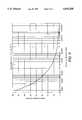
- FIG. 6illustrates battery lifetime as a function of depth of discharge.
- FIG. 1is a simplified block diagram of an electrical drive system, with an intelligent interface to a battery charger, for propelling a vehicle.
- the vehicle drive systemincludes an electric drive system controller 10 coupled to a circuit 12, which may constitute either a direct current (DC) to alternating current (AC) inverter or a direct current (DC) to direct current chopper controllable switching power supply, for operating one or more associated AC or DC drive motors 14.
- Drive system controller 10responds to brake commands from a brake pedal 16 or accelerator commands from an accelerator pedal 18 to control drive motor 14.
- a propulsion battery 20is connected to the vehicle drive system through contactors 21 and may be connected to a battery charger 24 which is either on-board or off-board the vehicle.
- Battery 20may constitute a battery pack including sensors 26, 28 and 30 for providing signals representing current, voltage and temperature, respectively.
- Sensor 30may comprise a plurality of temperature sensors, each coupled to a respective cell, or module containing a plurality of cells, of a multi-cell battery.
- Drive system controller 10may include a battery state of charge indicator block 32 and a battery charger status indicator 29.
- Battery charger 24is typically adapted to be connected to an AC source (not shown) via a connector 25.
- the electronic circuits necessary for implementing the system of FIG. 1are known in the art; however, if implemented in digital form, the functions of drive controller 10, non-volatile memory 34, voltage sensor 28, state of charge indicator 32 and possibly even battery charger controller 36 may be implemented in the same microcomputer.
- the vehicle drive systemmay be full electric drive such as is commonly used on golf cars, electric utility vehicles, or on-road electric vehicles or a hybrid electric/internal combustion engine drive of a type sometimes used for on-road vehicles.
- battery 20is called upon to supply power in cycles.
- a golf caris typically operated for several minutes and then parked for several minutes.
- a typical battery current profile for such operationis shown in FIG. 2 wherein the golf car key switch, represented as GSW, is "on” at level 1 and “off” at level 0.
- GSWthe golf car key switch
- current drawis high at start-up and then settles to a value for running during vehicle cruise at substantially constant loading.
- regenerative currentmay be supplied to the battery as the vehicle decelerates to a stop, as shown by the negative current.
- the ampere-hour (AH) usageis defined by ##EQU1## where IBat represents bipolar battery current (i.e., charge or negative current and discharge or positive current) and is a function of time, and T is the duration of a sub-cycle discharge.
- IBatbipolar battery current (i.e., charge or negative current and discharge or positive current) and is a function of time
- Tis the duration of a sub-cycle discharge.
- FIG. 3A typical charge/discharge pattern for an electric vehicle battery is shown in FIG. 3.
- the patternillustrates one or more discharge sub-cycles between each successive charge sub-cycle.
- the number of ampere-hours dischargedis calculated from the equation: ##EQU3## where T j is the time over the j th battery discharge sub-cycle.
- Each sub-cyclemay include regenerative braking.
- a discharge sub-cycleis defined as a sequence of battery discharge currents followed by a period of either zero discharge current, i.e., key switch turned off, or a recharge current from an auxiliary power unit (APU) in a hybrid vehicle.
- APUauxiliary power unit
- the average ampere-hours discharged from the battery over M sub-cycles occurring after the k th recharge cyclemay be represented as: ##EQU5## while the average discharge current during the j th sub-cycle may be represented as: ##EQU6##
- Total accumulated ampere-hours discharged from the battery since it was installed new in the vehiclemay be represented as: ##EQU7## where N is the number of recharge cycles since the battery was installed new in the vehicle. AccumAH, along with the depth of discharge of each subcycle discharge, is used as a projection of the life of the battery.
- ICHgBattery charge current into battery. IChg is of opposite polarity to IBat during discharge.
- PcOverchDesired percentage ampere-hour overcharge during the battery recharge operation. PcOverch is a function of battery age.
- BatTempMeasured battery temperature(s) in degrees Fahrenheit.
- PcSlfDispercent battery self discharge per hour. PcSlfDis is based on manufacturers' data or measurements, and is a function of battery temperature (BatTemp). PcSlfDis is often specified by manufacturer in percentage discharge per week.
- DisTimeTotal accumulated time (hours) since the propulsion battery became operational in the drive, i.e., was discharged and charged via regenerative braking (key switch "on") since the last complete battery recharge.
- NomAHCapNominal ampere-hour capacity for a new battery at the discharge rate specified by the manufacturer. NomAHCap is often referred to as "C"; for example, a 5 hour discharge is designated C5.
- AHCapAmpere-hour capacity of the battery while it is being discharged at a rate other than the rate specified by the manufacturer. AHCap is also a function of battery temperature, battery age (calendar life), and total accumulated ampere-hours discharged by the battery.
- AHTargetThe ampere-hour to be supplied by the charger during the next battery charge.
- Memory 34is addressable from battery charger 24 to allow charger 24 to determine the amount of charge required to return battery 20 to its fully charged state.
- Memory 34stores sensed and computed data during battery discharge. For example, memory 34 can sample and store battery temperature profile, ampere-hours charged, ampere-hours discharged, net ampere-hours discharged (ampere-hours discharged minus ampere-hours recovered during regenerative braking), average net discharge current, open circuit battery voltage profile, total accumulated ampere-hours discharged in each discharge cycle and total number of discharge cycles.
- memory 34stores such data as battery temperature profile, ampere-hours of charge, battery charge profile and charger status.
- Charger statuscan include an AC power failure, termination of charging, and battery charger faults.
- the accumulated dataare used by battery charger controller 36, which comprises a microprocessor, and drive system controller 10, which also comprises a microprocessor, to precisely charge battery 20.
- battery charger 24is exemplified as a transformerless, high frequency charger with a ground continuity detector 38, any type of controllable charger could be used with the control concept set forth herein.
- controller 36 and controller 10could be combined into a single controller.
- the AC power inputis preferably supplied through a set of controllable AC contactors 40 and an EMI (electromagnetic interference) filter 42 to a rectifier 44.
- the rectified poweris then supplied from rectifier 44 to a power conditioner 46 which regulates the voltage and current furnished to battery 20 in response to controller 36.
- charger 24is initially operated in a constant current mode, limited by the power available from the particular electric service connected to connector 25, until a temperature compensated voltage at the battery is achieved. Thereafter, the charger operates at a constant voltage, with current tapering to a low value that is a function of the battery parameters and consistent with the battery manufacturer's recommendation.
- Battery charge terminationis primarily based on supplying slightly over 100% of the ampere-hours during recharge, compared to the total net ampere-hours discharged since the last recharge. Other charge termination criteria are also applied as default values in the event that a fault should occur or if battery parameters were incorrectly stored in the software.
- a low level equalizing chargeneeds to be applied to the battery.
- Data computed in drive system controller 10 and stored in non-volatile memory 34are used to establish when the normal charge should automatically be followed by an equalizing charge. If the charge period does not allow this equalizing charge to be completed, then this information is presented to the driver through battery charger status indicator 29.
- the intelligent battery charger of the inventionprovides compensation to prevent overcharging of aged batteries.
- the computed state of chargeas shown by indicator 32 on the vehicle instrument panel, is compensated for the battery's reduced capacity as a result of battery age, operation at low battery temperatures, and excessive discharge rates.
- controller 36Operation of charger 24 is controlled by controller 36 in response to the measured parameters (current, voltage and battery temperature) and the stored data in memory 34. Once controller 36 has calculated the net ampere-hour discharge using the above equations, the amount of recharge current can be determined from the following relationships.
- the chargeroperates in two modes, i.e., constant current and constant voltage.
- the chargeroperates in a constant current mode until the battery voltage exceeds a temperature compensated value:
- Typical values for a Ni-Cd batteryare:
- Typical values for a lead-acid batteryare:
- V12.50V/cell when charged at a C/3 rate
- Tcoeff0.007V/(cell* °C.) where Btemp is the sensed battery temperature.
- the battery with the highest temperatureis used to set the voltage in the constant voltage mode of operation.
- FIG. 4is a plot of a typical lead acid battery recharge for initial operation in a constant current mode followed by a temperature compensated constant voltage mode. The curve is based on the following assumptions:
- An equalization charge(increased ampere-hour target plus a reduced voltage in the constant voltage mode of operation) is performed automatically by the charger control.
- the selection of when the equalization charge is performedis based on the value of AccumAH since the last equalization charge. For lead-acid batteries, manufacturers typically recommend one equalization charge after 10 to 20 normal charge cycles, or at least one equalization charge per calendar month.
- the number of ampere-hours to be provided by the charger during the K+1 th charge cycle, (provided the K th charge cycle was completed with "normal termination") for an equalization chargeis: ##EQU10## where PcOverchEq (i.e., the desired percentage ampere-hour overcharge during battery equalization charging) is typically 5-10% for a lead-acid battery equalization charge.
- IChg(t)IBat(t) with the polarity of IBat(t) during discharge
- the AHCapis a function of average discharge current that can be determined from either the Puekert relationship or from measured battery data such as shown in FIG. 5, which represents characteristics of an 80 ampere-hour capacity battery at discharge rates ranging from 16 amps continuous to 400 amps continuous. For many batteries, the AHCap is also a function of battery temperature. In general, the AHCap of a lead-acid battery operating at high discharge current exhibits a greater reduction in AHCap than does a Ni-Cd battery. An example of a battery state of charge indicator for an electrically powered vehicle is shown in U.S. Pat. No. 5,119,011 issued Jun. 2, 1992 and assigned to the instant assignee.
- Cycle lifeis a function of the depth of discharge (DOD) that the battery is operated at, as set forth in equation (13):
- FIG. 6shows a typical relationship between battery cycle life and DOD for a nickel-cadmium battery operated at +20° C. From FIG. 6, it is apparent that battery charging in an intelligent manner after a shallow discharge, i.e. "opportunity charging", whether from an external power source or from an auxiliary power unit in a hybrid vehicle, can significantly improve the life of the battery.
Landscapes
- Engineering & Computer Science (AREA)
- Power Engineering (AREA)
- Transportation (AREA)
- Mechanical Engineering (AREA)
- Life Sciences & Earth Sciences (AREA)
- Sustainable Development (AREA)
- Sustainable Energy (AREA)
- Charge And Discharge Circuits For Batteries Or The Like (AREA)
- Secondary Cells (AREA)
Abstract
Description
This invention relates to battery chargers and, more particularly, to a battery charger for use in charging batteries used in electrically propelled vehicles.
Commercial propulsion battery chargers, especially for off-road vehicles such as golf cars (either mounted on-board or off-board the vehicle), are usually designed as stand-alone units and are often manufactured by a different company than the supplier of the propulsion drive system. Battery voltage, charge current, and sometimes the slope of the charge current and/or the slope of the battery voltage versus time near the end of charge are used in the control of these commercial battery chargers. Today's commercial chargers with their unsophisticated control tend to overcharge the batteries, or improperly charge either aged batteries or batteries that are at temperatures significantly different than 80° F. Overcharging wastes energy, increases the required battery watering maintenance, and significantly reduces battery life. Maintenance personnel errors, including failure to start the charger or premature termination of the charge function, are often not detected. If the battery is not properly charged, then during the next use cycle, excessive discharge may occur and result in reduced battery life and poor vehicle performance.
The above and other disadvantages of prior battery chargers are overcome in a system in which the net ampere-hour discharge of a cyclically operated battery is computed from measured samples of discharge current. In addition to measured samples of battery current, measured samples of battery voltage and battery temperature provide a corresponding profile of these key parameters during the discharge. The battery is then recharged with an equivalent ampere-hour of charge. The system periodically adds an equalizing charge to the battery in addition to the normal charge. In addition, the battery state of charge is compensated for the battery's reduced capacity with aging, operation at low temperature and excessive current discharge rates. The state of charge is displayed for viewing by a vehicle operator.
The invention is implemented in a microprocessor controlled vehicle drive system and a microprocessor controlled battery charger. The control system or "controller" for the battery charger is coupled for monitoring battery current, battery voltage and battery temperature, and periodically stores such data in a non-volatile memory. During a recharge cycle, the charger controller accesses the memory to retrieve the discharge history for the battery. The discharge data are then manipulated to determine the net ampere-hours of discharge. The charger controller then computes a target recharge ampere-hour value equal to the net ampere-hours discharged plus an overcharge amount. During recharge, the charger initially operates in a constant current mode until a predetermined voltage level, compensated for temperature, is reached. Thereafter, the charger operates in a constant voltage mode with decreasing current until slightly more ampere-hours of recharge is supplied to the battery than was withdrawn during battery use. If a fault should occur during the charging process, the charger stores an indication of the ampere hours charged prior to terminating the charge. Faults include, for example, an AC power failure, or the measured battery parameters (voltage or temperature) being out of the range allowed for the battery under charge.
The features of the invention believed to be novel are set forth in the appended claims. The invention, however, together with further objects and advantages thereof, may best be understood by reference to the following description taken in conjunction with the accompanying drawing(s) in which:
FIG. 1 is a simplified block diagram of an electric vehicle drive system and battery charger incorporating the teaching of the present invention;
FIG. 2 is a graph of battery discharge current versus time for cyclical operation of an electric vehicle with a regenerative braking mode of operation;
FIG. 3 is a chart illustrating charge and discharge cycles over the life of a rechargeable battery;
FIG. 4 is a graph illustrating recharge of a battery as a function of time;
FIG. 5 illustrates discharge characteristics of a Ni-Cd battery; and
FIG. 6 illustrates battery lifetime as a function of depth of discharge.
FIG. 1 is a simplified block diagram of an electrical drive system, with an intelligent interface to a battery charger, for propelling a vehicle. The vehicle drive system includes an electricdrive system controller 10 coupled to acircuit 12, which may constitute either a direct current (DC) to alternating current (AC) inverter or a direct current (DC) to direct current chopper controllable switching power supply, for operating one or more associated AC orDC drive motors 14.Drive system controller 10 responds to brake commands from abrake pedal 16 or accelerator commands from anaccelerator pedal 18 to controldrive motor 14. Apropulsion battery 20 is connected to the vehicle drive system throughcontactors 21 and may be connected to abattery charger 24 which is either on-board or off-board the vehicle.Battery 20 may constitute a batterypack including sensors Sensor 30 may comprise a plurality of temperature sensors, each coupled to a respective cell, or module containing a plurality of cells, of a multi-cell battery.Drive system controller 10 may include a battery state ofcharge indicator block 32 and a batterycharger status indicator 29.Battery charger 24 is typically adapted to be connected to an AC source (not shown) via aconnector 25. The electronic circuits necessary for implementing the system of FIG. 1 are known in the art; however, if implemented in digital form, the functions ofdrive controller 10,non-volatile memory 34, voltage sensor 28, state ofcharge indicator 32 and possibly evenbattery charger controller 36 may be implemented in the same microcomputer.
The vehicle drive system may be full electric drive such as is commonly used on golf cars, electric utility vehicles, or on-road electric vehicles or a hybrid electric/internal combustion engine drive of a type sometimes used for on-road vehicles. During vehicle operation,battery 20 is called upon to supply power in cycles. For example, a golf car is typically operated for several minutes and then parked for several minutes. A typical battery current profile for such operation is shown in FIG. 2 wherein the golf car key switch, represented as GSW, is "on" atlevel 1 and "off" atlevel 0. As shown in FIG. 2, after the key switch is turned "on", current draw is high at start-up and then settles to a value for running during vehicle cruise at substantially constant loading. If the vehicle is operated on hilly terrain, regenerative current may be supplied to the battery as the vehicle decelerates to a stop, as shown by the negative current. The ampere-hour (AH) usage is defined by ##EQU1## where IBat represents bipolar battery current (i.e., charge or negative current and discharge or positive current) and is a function of time, and T is the duration of a sub-cycle discharge. If the system is microprocessor controlled using an analog-to-digital converter, the AH discharge is defined by ##EQU2## where Δt=tN -tN-1 and L=total number of samples of battery current.
A typical charge/discharge pattern for an electric vehicle battery is shown in FIG. 3. The battery is initially charged during a first charge cycle K=1 and then put into service at the end of this charge cycle. Several sub-cycles M of discharge (such as, for example, M=3) may occur before the next charge cycle K=2. Thereafter, the pattern illustrates one or more discharge sub-cycles between each successive charge sub-cycle. The number of ampere-hours discharged is calculated from the equation: ##EQU3## where Tj is the time over the jth battery discharge sub-cycle. Each sub-cycle may include regenerative braking.
A discharge sub-cycle is defined as a sequence of battery discharge currents followed by a period of either zero discharge current, i.e., key switch turned off, or a recharge current from an auxiliary power unit (APU) in a hybrid vehicle. For example, with reference to FIG. 2: ##EQU4## where AHNet represents net ampere-hours discharged from the battery accumulated during operation since the last complete battery recharge, and M is the total number of discharge sub-cycles after the kth charge cycle.
The average ampere-hours discharged from the battery over M sub-cycles occurring after the kth recharge cycle may be represented as: ##EQU5## while the average discharge current during the jth sub-cycle may be represented as: ##EQU6##
Idle time is the total time (in hours) since the last complete, normal termination battery charge (at time To) when the battery was neither being charged or discharged; i.e., the key switch was "off" (GSW=0).
Total accumulated ampere-hours discharged from the battery since it was installed new in the vehicle may be represented as: ##EQU7## where N is the number of recharge cycles since the battery was installed new in the vehicle. AccumAH, along with the depth of discharge of each subcycle discharge, is used as a projection of the life of the battery.
The following definitions are used in equations 9-14:
1. ICHg=Battery charge current into battery. IChg is of opposite polarity to IBat during discharge.
2. PcOverch=Desired percentage ampere-hour overcharge during the battery recharge operation. PcOverch is a function of battery age.
3. BatTemp=Measured battery temperature(s) in degrees Fahrenheit.
4. PcSlfDis=percent battery self discharge per hour. PcSlfDis is based on manufacturers' data or measurements, and is a function of battery temperature (BatTemp). PcSlfDis is often specified by manufacturer in percentage discharge per week.
5. DisTime=Total accumulated time (hours) since the propulsion battery became operational in the drive, i.e., was discharged and charged via regenerative braking (key switch "on") since the last complete battery recharge.
6. NomAHCap=Nominal ampere-hour capacity for a new battery at the discharge rate specified by the manufacturer. NomAHCap is often referred to as "C"; for example, a 5 hour discharge is designated C5.
7. AHCap=Ampere-hour capacity of the battery while it is being discharged at a rate other than the rate specified by the manufacturer. AHCap is also a function of battery temperature, battery age (calendar life), and total accumulated ampere-hours discharged by the battery.
8. AHTarget=The ampere-hour to be supplied by the charger during the next battery charge.
Information or data necessary to perform the above calculations are stored in anon-volatile memory 34, shown in FIG. 1, during operation of the vehicle drive system.Memory 34 is addressable frombattery charger 24 to allowcharger 24 to determine the amount of charge required to returnbattery 20 to its fully charged state.Memory 34 stores sensed and computed data during battery discharge. For example,memory 34 can sample and store battery temperature profile, ampere-hours charged, ampere-hours discharged, net ampere-hours discharged (ampere-hours discharged minus ampere-hours recovered during regenerative braking), average net discharge current, open circuit battery voltage profile, total accumulated ampere-hours discharged in each discharge cycle and total number of discharge cycles. During battery charging,memory 34 stores such data as battery temperature profile, ampere-hours of charge, battery charge profile and charger status. Charger status can include an AC power failure, termination of charging, and battery charger faults. The accumulated data are used bybattery charger controller 36, which comprises a microprocessor, anddrive system controller 10, which also comprises a microprocessor, to precisely chargebattery 20.
Althoughbattery charger 24 is exemplified as a transformerless, high frequency charger with aground continuity detector 38, any type of controllable charger could be used with the control concept set forth herein. Furthermore, in the special case wherecharger 24 is integrated into the vehicle drive system,controller 36 andcontroller 10 could be combined into a single controller. The AC power input is preferably supplied through a set ofcontrollable AC contactors 40 and an EMI (electromagnetic interference)filter 42 to arectifier 44. The rectified power is then supplied fromrectifier 44 to apower conditioner 46 which regulates the voltage and current furnished tobattery 20 in response tocontroller 36.
During battery charging,charger 24 is initially operated in a constant current mode, limited by the power available from the particular electric service connected toconnector 25, until a temperature compensated voltage at the battery is achieved. Thereafter, the charger operates at a constant voltage, with current tapering to a low value that is a function of the battery parameters and consistent with the battery manufacturer's recommendation. Battery charge termination is primarily based on supplying slightly over 100% of the ampere-hours during recharge, compared to the total net ampere-hours discharged since the last recharge. Other charge termination criteria are also applied as default values in the event that a fault should occur or if battery parameters were incorrectly stored in the software.
Periodically, a low level equalizing charge needs to be applied to the battery. Data computed indrive system controller 10 and stored innon-volatile memory 34 are used to establish when the normal charge should automatically be followed by an equalizing charge. If the charge period does not allow this equalizing charge to be completed, then this information is presented to the driver through batterycharger status indicator 29.
The intelligent battery charger of the invention provides compensation to prevent overcharging of aged batteries. In addition, the computed state of charge, as shown byindicator 32 on the vehicle instrument panel, is compensated for the battery's reduced capacity as a result of battery age, operation at low battery temperatures, and excessive discharge rates.
Operation ofcharger 24 is controlled bycontroller 36 in response to the measured parameters (current, voltage and battery temperature) and the stored data inmemory 34. Oncecontroller 36 has calculated the net ampere-hour discharge using the above equations, the amount of recharge current can be determined from the following relationships.
If the Kth charge cycle was completed with normal termination, i.e., not prematurely terminated, the number of ampere-hours to be delivered to the battery during the K+1 charge cycle is: AH TargetK+1. Thus ##EQU8## where PcOverch is typically 2-5% for lead-acid or 0.5-1.0% for nickel-cadmium (Ni-Cd) batteries for "normal" i.e. non-equalizing charge.
If the Kth charge cycle was not "normal termination", i.e., charge was terminated due to a power failure, manual termination in error by operator, or terminated as a result of a fault or blown fuse, then: ##EQU9## where AHChgk is the integral of ICHg(t), (IChg(t)=-IBat(t) during battery charging) integrated from the time the charge started until it was prematurely terminated.
The charger operates in two modes, i.e., constant current and constant voltage. The charger operates in a constant current mode until the battery voltage exceeds a temperature compensated value:
VperCell>V1-Tcoeff*(Btemp-20° C.)
Typical values for a Ni-Cd battery are:
V1=1.55V/cell when charged at a C/5 rate, and Tcoeff=0.004V/(cell* °C.)
Typical values for a lead-acid battery are:
V1=2.50V/cell when charged at a C/3 rate, and Tcoeff=0.007V/(cell* °C.) where Btemp is the sensed battery temperature.
If multiple battery temperature sensors are utilized, the battery with the highest temperature is used to set the voltage in the constant voltage mode of operation.
FIG. 4 is a plot of a typical lead acid battery recharge for initial operation in a constant current mode followed by a temperature compensated constant voltage mode. The curve is based on the following assumptions:
40.71 AH discharge
5.52 AH regenerative
35.19 AHNet
37.23 AH charge, for 106% net AH recharge.
An equalization charge (increased ampere-hour target plus a reduced voltage in the constant voltage mode of operation) is performed automatically by the charger control. The selection of when the equalization charge is performed is based on the value of AccumAH since the last equalization charge. For lead-acid batteries, manufacturers typically recommend one equalization charge after 10 to 20 normal charge cycles, or at least one equalization charge per calendar month.
The number of ampere-hours to be provided by the charger during the K+1th charge cycle, (provided the Kth charge cycle was completed with "normal termination") for an equalization charge is: ##EQU10## where PcOverchEq (i.e., the desired percentage ampere-hour overcharge during battery equalization charging) is typically 5-10% for a lead-acid battery equalization charge.
Charge termination criteria are as follows:
for "normal termination"
1. |AHChgK |≧|AHTargetK |
2. Charge Time>Maximum allowable charge time
For "fault termination":
1. Btemp>Battery Temperature Limit
2. |IChg(t)|>Charger maximum current limit
where IChg(t)=IBat(t) with the polarity of IBat(t) during discharge
3. |IChg(t)|<Charger minimum current limit
Battery state of charge (SOC) is estimated by using the computed value of AHNet during each sub-cycle and the computed ampere hour capacity (AHCap), in accordance with equation (12):
SOC=(AHNet/AHCap)*100%. (12)
The AHCap is a function of average discharge current that can be determined from either the Puekert relationship or from measured battery data such as shown in FIG. 5, which represents characteristics of an 80 ampere-hour capacity battery at discharge rates ranging from 16 amps continuous to 400 amps continuous. For many batteries, the AHCap is also a function of battery temperature. In general, the AHCap of a lead-acid battery operating at high discharge current exhibits a greater reduction in AHCap than does a Ni-Cd battery. An example of a battery state of charge indicator for an electrically powered vehicle is shown in U.S. Pat. No. 5,119,011 issued Jun. 2, 1992 and assigned to the instant assignee.
Cycle life is a function of the depth of discharge (DOD) that the battery is operated at, as set forth in equation (13):
DOD=Depth of Discharge=(1-SOC)*100%. (13)
FIG. 6 shows a typical relationship between battery cycle life and DOD for a nickel-cadmium battery operated at +20° C. From FIG. 6, it is apparent that battery charging in an intelligent manner after a shallow discharge, i.e. "opportunity charging", whether from an external power source or from an auxiliary power unit in a hybrid vehicle, can significantly improve the life of the battery.
While only certain preferred features of the invention have been illustrated and described, many modifications and changes will occur to those skilled in the art. It is, therefore, to be understood that the appended claims are intended to cover all such modifications and changes as fall within the true spirit of the invention.
Claims (26)
1. A battery charger comprising:
regulating means for receiving substantially constant voltage power and conditioning the power for application to a battery to be charged;
control means coupled to said regulating means and adapted to control said regulating means to introduce a controlled amount of electrical charge to the battery;
monitoring means operatively associated with the battery for monitoring net discharge current, as a function of time, from the battery during an interval between recharge cycles and for storing data representative of the net discharge current as a function of time, said monitoring means including means for converting said net discharge current as a function of time into net ampere-hour discharge data; and
means for providing said discharge data from said monitoring means to said control means for establishing a total recharge ampere-hours to the battery in an amount corresponding to the net amount of discharge ampere-hours.
2. The battery charger of claim 1 including means for compensating the total recharge ampere-hours by an amount determined from the age of the battery.
3. The battery charger of claim 2 including means for tracking the number of occurrences of recharge of the battery and the accumulated ampere-hours and for applying an equalizing charge to the battery after a predetermined number of recharge occurrences and accumulated ampere-hours since a last equalizing charge.
4. The battery charger of claim 3 including means for sensing battery temperature and for adjusting recharge constant voltage profile inversely with temperature.
5. The battery charger of claim 4 wherein said monitoring means includes means for computing and displaying the battery state of charge from said monitored net ampere-hours of discharge.
6. The battery charger of claim 5 including means for compensating said battery state of charge as a function of battery age and sensed battery temperature.
7. The battery charger of claim 6 wherein said constant voltage power comprises alternating current and said power conditioning means includes a rectifier circuit for converting said alternating current to direct current and a switching power regulator for conditioning said direct current to a value suitable for application to the battery.
8. The battery charger of claim 7 including a ground continuity check circuit for disabling operation of said battery charger upon detection of an open ground condition.
9. The battery charger of claim 8 wherein the battery comprises a plurality of independent cells and the battery temperature sensing means includes means for sensing temperature of each independent cell.
10. The battery charger of claim 8 wherein the battery comprises a plurality of independent cells within at least one battery module, and the battery temperature sensing means includes means for sensing temperature of said at least one battery module.
11. A method for charging a rechargeable battery pack, comprising the steps of;
sensing discharge current of the battery pack as a function of time;
computing, from the sensed discharge current and time duration of discharge, net ampere-hours discharged by the battery; and
recharging the battery until at least the computed net ampere-hours of discharge is returned to the battery.
12. The method of claim 11 including the further step of computing an excess ampere-hour charge for overcharging the battery.
13. The method of claim 11 wherein the battery is coupled to supply power to an electrical drive system of an electrical motor propelled vehicle, the vehicle being operative in an electrically regenerative braking mode wherein the motor operates as an electrical power generator, the method comprising the further steps of:
sensing current supplied from the motor to the battery as a function of time during electrical braking; and
computing total ampere-hours of charge supplied to the battery;
wherein the step of computing the net ampere-hours discharged from the battery includes subtracting the total ampere-hours of charge from a total ampere-hours of discharge.
14. A battery charger for a battery coupled for supplying power to an electric drive system of an electric motor propelled vehicle, the vehicle being selectively operative in an electrical braking mode wherein the motor operates as an electrical generator for returning power to the battery, the charger comprising:
regulating means for receiving substantially constant voltage power and conditioning the power for application to a battery to be charged;
control means coupled to said regulating means and adapted to control said regulating means to introduce a controlled amount of electrical charge to the battery; and
monitoring means coupled to the battery for measuring total discharge current, as a function of time, from the battery while the motor is operative in a propulsion mode and for measuring total charge current, as a function of time, while the motor is operative in a braking mode, said monitoring means including means for converting said measured charge and discharge currents to a net ampere-hours of discharge;
said control means being coupled to said monitoring means for establishing operation of the battery charger to recharge the battery with an amount of electrical charge corresponding to at least said net ampere-hours of discharge.
15. The method of claim 11 wherein the step of computing net ampere-hours discharged by the battery comprises periodically recharging the battery during a recharge cycle and computing the net ampere-hours discharged between successive recharge cycles.
16. The method of claim 15 including the step of storing data representative of a total number of recharge cycles, a depth of discharge for each period between recharge cycles, and total ampere-hours discharged from the battery for all discharge intervals.
17. The method of claim 15 wherein the step of recharging the battery comprises recharging the battery in a constant current mode until battery voltage equals a selected voltage limit and thereafter recharging the battery in a constant voltage mode until the net ampere-hours of discharge has been returned to the battery.
18. The method of claim 17 including the steps of sensing battery temperature and compensating the selected voltage limit inversely with sensed battery temperature.
19. The method of claim 18 including the step of increasing net ampere-hours of recharge by a variable amount specified for the battery.
20. The method of claim 19 including the step of compensating the net ampere-hours of recharge for battery self-discharge when the battery is not under load.
21. The method of claim 20 including the steps of computing a relative age of the battery from the stored data and modifying the recharge cycle and net ampere-hours of recharge as a function of the relative age.
22. The method of claim 21 including the step of terminating a recharge cycle when said constant voltage mode is maintained for at least a selected time period.
23. The method of claim 22 including the step of displaying battery state of charge computed from said net ampere-hours of discharge.
24. The method of claim 19 wherein said variable amount is in the range of about 2% to 5% of net ampere-hour discharge between charge cycles.
25. The method of claim 18 wherein the selected voltage limit is computed from
VperCell=V1-Tcoeff*(Btemp-20° C.)
where VperCell is the selected voltage limit per cell, V1 is an ideal per cell battery voltage, Tcoeff is a battery temperature coefficient in volts per cell per degree centigrade and Btemp is sensed battery temperature.
26. A battery charger for a battery coupled for supplying power to an electric drive system of an electric motor propelled hybrid vehicle, the vehicle having an internal combustion engine coupled to electric generating means for providing the vehicle with propulsion power at selected times and for controllably charging the battery, the vehicle being selectively operative in an electrical braking mode wherein the motor operates as an electrical generator for returning power to the battery, the charger comprising:
regulating means for receiving substantially constant voltage power and conditioning the power for application to a battery to be charged;
control means coupled to said regulating means and adapted to control said regulating means to introduce a controlled amount of electrical charge to the battery; and
monitoring means coupled to the battery for measuring total discharge current, as a function of time, from the battery while the motor is operative in a propulsion mode, for measuring total charge current, as a function of time, while the motor is operative in a braking mode, and for measuring electrical power returned to the battery during operation of said engine, said monitoring means including means for converting said measured charge and discharge currents to a net ampere-hours of discharge and for adjusting said net ampere-hours of discharge by an amount corresponding to said measured electrical power;
said control means being coupled to said monitoring means for establishing operation of the battery charger to recharge the battery with an amount of electrical charge corresponding to at least said net ampere-hours of discharge.
Priority Applications (1)
| Application Number | Priority Date | Filing Date | Title |
|---|---|---|---|
| US08/390,205US5659240A (en) | 1995-02-16 | 1995-02-16 | Intelligent battery charger for electric drive system batteries |
Applications Claiming Priority (1)
| Application Number | Priority Date | Filing Date | Title |
|---|---|---|---|
| US08/390,205US5659240A (en) | 1995-02-16 | 1995-02-16 | Intelligent battery charger for electric drive system batteries |
Publications (1)
| Publication Number | Publication Date |
|---|---|
| US5659240Atrue US5659240A (en) | 1997-08-19 |
Family
ID=23541546
Family Applications (1)
| Application Number | Title | Priority Date | Filing Date |
|---|---|---|---|
| US08/390,205Expired - LifetimeUS5659240A (en) | 1995-02-16 | 1995-02-16 | Intelligent battery charger for electric drive system batteries |
Country Status (1)
| Country | Link |
|---|---|
| US (1) | US5659240A (en) |
Cited By (111)
| Publication number | Priority date | Publication date | Assignee | Title |
|---|---|---|---|---|
| US5804945A (en)* | 1995-11-07 | 1998-09-08 | Furukawa Denchi Kabushiki Kaisha | DC power supply system with automatic recharging for storage battery |
| US5965996A (en)* | 1997-12-11 | 1999-10-12 | Vectrix Corporation | Electrical scooter having an equalization circuit for charging multiple batteries |
| US5969624A (en)* | 1995-04-07 | 1999-10-19 | Nippon Soken, Inc, | Battery charge control system for a hybrid vehicle driven by an electric motor and an internal combustion engine |
| US5998960A (en)* | 1997-03-25 | 1999-12-07 | Fuji Electric Co., Ltd. | Power supply system for electric vehicle |
| US6011379A (en)* | 1997-03-12 | 2000-01-04 | U.S. Nanocorp, Inc. | Method for determining state-of-charge using an intelligent system |
| US6018234A (en)* | 1996-09-16 | 2000-01-25 | Valeo Equipment Electriques Moteur | Regulating system for an alternator voltage |
| US6087805A (en)* | 1995-04-14 | 2000-07-11 | Langston; Charles R. | Monitoring and controlling system for battery and battery charger |
| US6091228A (en)* | 1998-04-29 | 2000-07-18 | Lockheed Martin Corp. | Control system for, in the presence of a varying system load, establishing generator current to maintain a particular battery charge state |
| US6091229A (en)* | 1999-03-30 | 2000-07-18 | Motorola, Inc. | Sub-miniature high efficiency battery charger system and method |
| US6106968A (en)* | 1998-03-06 | 2000-08-22 | Lucent Technologies Inc. | Smart valve regulated lead acid battery with embedded electronic monitoring and fluid fill system |
| US6157169A (en)* | 1997-04-30 | 2000-12-05 | Samsung Electronics Co., Ltd. | Monitoring technique for accurately determining residual capacity of a battery |
| US6215198B1 (en)* | 1996-06-25 | 2001-04-10 | Nissan Motor Co., Ltd. | Generating control device for hybrid vehicle |
| US6331365B1 (en) | 1998-11-12 | 2001-12-18 | General Electric Company | Traction motor drive system |
| AU750930B2 (en)* | 1999-09-22 | 2002-08-01 | Honda Giken Kogyo Kabushiki Kaisha | Control apparatus for hybrid vehicles |
| US6441581B1 (en) | 2001-03-20 | 2002-08-27 | General Electric Company | Energy management system and method |
| US6456988B1 (en) | 1997-03-12 | 2002-09-24 | U.S. Nanocorp Inc. | Method for determining state-of-health using an intelligent system |
| EP1065773A3 (en)* | 1999-07-02 | 2002-11-06 | Yazaki Corporation | Battery capacity measurement apparatus, taking into consideration a gassing voltage that changes relative to temperature |
| EP1065772A3 (en)* | 1999-07-02 | 2002-11-20 | Yazaki Corporation | Battery charge control device having a gassing detection unit without temperature sensor |
| US20030151387A1 (en)* | 2001-03-27 | 2003-08-14 | General Electric Company | Hybrid energy off highway vehicle electric power management system and method |
| US20030150352A1 (en)* | 2001-03-27 | 2003-08-14 | General Electric Company | Hybrid energy off highway vehicle electric power storage system and method |
| US20030233959A1 (en)* | 2001-03-27 | 2003-12-25 | General Electric Company | Multimode hybrid energy railway vehicle system and method |
| US20040012396A1 (en)* | 2001-04-06 | 2004-01-22 | Microchip Technology Incorporated | Battery cover assembly having integrated battery condition monitoring |
| US20040111320A1 (en)* | 2002-12-05 | 2004-06-10 | Jorg Schlieffers | Electronic shopping system |
| US20040178635A1 (en)* | 2003-03-10 | 2004-09-16 | Government Of United States Of America | Methods of operating a parallel hybrid vehicle |
| US20040212342A1 (en)* | 2001-04-06 | 2004-10-28 | Microchip Technology Incorporated | Battery cover assembly having integrated battery condition monitoring |
| US20040238243A1 (en)* | 2003-06-02 | 2004-12-02 | General Electric Company | Hybrid vehicle power control systems and methods |
| US20040239288A1 (en)* | 2003-05-29 | 2004-12-02 | Harrison John Springer | Methods and apparatus for operating electric vehicles |
| US20050005814A1 (en)* | 2001-03-27 | 2005-01-13 | General Electric Company | Hybrid energy off highway vehicle propulsion circuit |
| US20050024001A1 (en)* | 2002-02-27 | 2005-02-03 | Donnelly Frank Wegner | Method for monitoring and controlling traction motors in locomotives |
| US20050039630A1 (en)* | 2001-03-27 | 2005-02-24 | General Electric Company | Hybrid energy off highway vehicle load control system and method |
| US20050040789A1 (en)* | 2003-08-18 | 2005-02-24 | General Electric Company | Vehicle energy storage system control methods and method for determining battery cycle life projection for heavy duty hybrid vehicle applications |
| US20050045058A1 (en)* | 2003-08-26 | 2005-03-03 | Donnelly Frank Wegner | Method for monitoring and controlling locomotives |
| US20050134221A1 (en)* | 2003-12-05 | 2005-06-23 | Toru Wanibuchi | Charge control device |
| US20050145425A1 (en)* | 2003-09-25 | 2005-07-07 | Govt. Of The U.S.A. As Represented By The Admi. Of The U.S. Environmental Protection Agency | Methods of operating a series hybrid vehicle |
| US20050189886A1 (en)* | 2004-02-17 | 2005-09-01 | Railpower Technologies Corp. | Predicting wheel slip and skid in a locomotive |
| US20050269995A1 (en)* | 2004-05-17 | 2005-12-08 | Railpower Technologies Corp. | Design of a Large battery pack for a hybrid locomotive |
| US20050275408A1 (en)* | 2004-06-14 | 2005-12-15 | John Houldsworth | Method and apparatus for detecting impedance |
| US20050284676A1 (en)* | 2004-06-28 | 2005-12-29 | King Robert D | Hybrid electric propulsion system and method |
| US20060005736A1 (en)* | 2001-03-27 | 2006-01-12 | General Electric Company | Hybrid energy off highway vehicle electric power management system and method |
| US20060005738A1 (en)* | 2001-03-27 | 2006-01-12 | Kumar Ajith K | Railroad vehicle with energy regeneration |
| US20060005737A1 (en)* | 2001-03-27 | 2006-01-12 | General Electric Company | Hybrid energy off highway vehicle electric power storage system and method |
| US20060012333A1 (en)* | 2004-07-15 | 2006-01-19 | John Houldsworth | One time operating state detecting method and apparatus |
| US20060012320A1 (en)* | 2001-03-27 | 2006-01-19 | General Electric Company | Multimode hybrid energy railway vehicle system and method |
| US20060071645A1 (en)* | 2004-09-27 | 2006-04-06 | Oshkosh Truck Corporation | Status indicator for an energy storage device for use with an electric vehicle |
| US20060125319A1 (en)* | 2004-12-15 | 2006-06-15 | King Robert D | System and method for providing power control of an energy storage system |
| US7068036B1 (en) | 2003-10-28 | 2006-06-27 | Wiwilson Greatbatch Technologies, Inc. | Lithium/carbon monofluoride (Li/CFx) electrochemical cell projection model |
| US20060214637A1 (en)* | 2005-03-22 | 2006-09-28 | Philip Gonzales | High voltage hybrid battery pack cycler |
| US20060266256A1 (en)* | 2005-04-25 | 2006-11-30 | Railpower Technologies Corp. | Multiple prime power source locomotive control |
| US20070139016A1 (en)* | 2005-12-20 | 2007-06-21 | General Electric Company | Battery charging system and methods |
| US20070152639A1 (en)* | 2006-01-05 | 2007-07-05 | Miller Shane T | Battery charger with temperature compensation |
| US7304445B2 (en) | 2004-08-09 | 2007-12-04 | Railpower Technologies Corp. | Locomotive power train architecture |
| US20080007208A1 (en)* | 2006-06-30 | 2008-01-10 | Scientific-Atlanta, Inc. | Systems and Methods of Profiling Power Cycles in an Electronics Device |
| US20080066476A1 (en)* | 2006-09-20 | 2008-03-20 | Ford Global Technologies, Llc | System and method for controlling temperature of an energy storage device in a vehicle |
| US7349797B2 (en) | 2004-03-30 | 2008-03-25 | Railpower Technologies Corp | Emission management for a hybrid locomotive |
| US20080150490A1 (en)* | 2006-12-22 | 2008-06-26 | Christopher Richard Koziara | Controlling state of charge of a vehicle battery |
| GB2445656A (en)* | 2007-01-12 | 2008-07-16 | Ford Global Tech Llc | A power supply for a hybrid electric vehicle |
| WO2008107158A1 (en)* | 2007-03-05 | 2008-09-12 | Varta Automotive Systems Gmbh | Method and device for determining an equalizing charge of an accumulator |
| US20080291879A1 (en)* | 2007-05-22 | 2008-11-27 | Duff Adam C | Man-Portable Incident Command Platform |
| US20080315843A1 (en)* | 2007-06-25 | 2008-12-25 | Ramesh Chandra Bhardwaj | Methods and systems for battery charging management |
| EP1648048A3 (en)* | 2004-08-13 | 2009-04-22 | Ing. Büro M. Kyburz AG | Method for Optimizing the Cycle Life of Traction Batteries |
| US7528579B2 (en)* | 2003-10-23 | 2009-05-05 | Schumacher Electric Corporation | System and method for charging batteries |
| US7565867B2 (en) | 2004-09-03 | 2009-07-28 | Frank Wegner Donnelly | Multiple engine locomotive configuration |
| US20090206779A1 (en)* | 2003-07-09 | 2009-08-20 | Aloys Wobben | Motor vehicle |
| US20090250277A1 (en)* | 2007-01-12 | 2009-10-08 | Grand Kerry E | Battery Equalization Using a Plug-In Charger in a Hybrid Electric Vehicle |
| US20100019726A1 (en)* | 2008-07-24 | 2010-01-28 | General Electric Company | Method and system for control of a vehicle energy storage device |
| US20100019718A1 (en)* | 2008-07-24 | 2010-01-28 | General Electric Company | Method and system for extending life of a vehicle energy storage device |
| US7661370B2 (en) | 2005-10-19 | 2010-02-16 | Railpower, Llc | Design of a large low maintenance battery pack for a hybrid locomotive |
| US20100079115A1 (en)* | 2008-09-30 | 2010-04-01 | Lubawy Andrea L | Systems and methods for absorbing waste electricity from regenerative braking in hybridized vehicles |
| DE102009025132A1 (en)* | 2009-06-17 | 2010-12-23 | Bayerische Motoren Werke Aktiengesellschaft | Energy storage charging system |
| US7940016B2 (en) | 2004-08-09 | 2011-05-10 | Railpower, Llc | Regenerative braking methods for a hybrid locomotive |
| US7956615B1 (en) | 2007-02-27 | 2011-06-07 | Rf Micro Devices, Inc. | Utilizing computed battery resistance as a battery-life indicator in a mobile terminal |
| US7962109B1 (en)* | 2007-02-27 | 2011-06-14 | Rf Micro Devices, Inc. | Excess current and saturation detection and correction in a power amplifier |
| US7977919B1 (en) | 2005-04-06 | 2011-07-12 | Rf Micro Devices, Inc. | Over-voltage protection accounting for battery droop |
| US20110170318A1 (en)* | 2010-01-12 | 2011-07-14 | Ford Global Technologies, Llc | Variable Voltage Converter (VVC) with Integrated Battery Charger |
| US20110216453A1 (en)* | 2010-03-08 | 2011-09-08 | Pass & Seymour, Inc. | Protective device for an electrical supply facility |
| US20110216452A1 (en)* | 2010-03-08 | 2011-09-08 | Pass & Seymour, Inc. | Protective device for an electrical supply facility |
| US20110216451A1 (en)* | 2010-03-08 | 2011-09-08 | Pass & Seymour, Inc. | Protective device for an electrical supply facility |
| US20110241580A1 (en)* | 2010-03-31 | 2011-10-06 | Rockwell Automation Technologies, Inc. | Motor drive system with bus voltage control |
| US20120139475A1 (en)* | 2009-08-06 | 2012-06-07 | Rhodri Evans | Method and Apparatus for Charging a Lead Acid Battery |
| CN102574477A (en)* | 2009-10-19 | 2012-07-11 | 罗伯特·博世有限公司 | Method and charge controller for increasing the service life of secondary batteries |
| CN101741126B (en)* | 2009-12-07 | 2012-07-11 | 奇瑞汽车股份有限公司 | System for preventing over-discharge of automobile starting storage battery and control method thereof |
| CN102759411A (en)* | 2012-07-16 | 2012-10-31 | 力帆实业(集团)股份有限公司 | Temperature and humidity monitoring system of battery pack |
| US20130244828A1 (en)* | 2012-03-19 | 2013-09-19 | Honda Motor Co., Ltd. | Control apparatus for electric vehicle |
| US20140117927A1 (en)* | 2012-10-30 | 2014-05-01 | Texas Instruments Incorporated | Multifunction Single Antenna for Contactless Systems |
| US20140167680A1 (en)* | 2012-12-18 | 2014-06-19 | Hyundai Motor Company | System and method for periodically charging sub-battery for electric vehicle |
| US8768549B2 (en) | 2011-11-04 | 2014-07-01 | Tennant Company | Battery maintenance system |
| US8829855B2 (en) | 2012-09-26 | 2014-09-09 | Kohler Co. | Power generation system that optimizes the power provided to start a generator |
| WO2015086745A1 (en)* | 2013-12-11 | 2015-06-18 | Ecosynrg Ltd | Electric charging system and method |
| US20150207344A1 (en)* | 2014-01-17 | 2015-07-23 | General Electric Company | Configurable hybrid energy storage system and method |
| US9151232B2 (en) | 2001-03-27 | 2015-10-06 | General Electric Company | Control system and method |
| US9193268B2 (en) | 2001-03-27 | 2015-11-24 | General Electric Company | Hybrid energy power management system and method |
| US9219294B2 (en) | 2012-08-22 | 2015-12-22 | Eric D. Albsmeier | Power management system that changes the operating conditions of a battery charger |
| JP2016007121A (en)* | 2014-05-27 | 2016-01-14 | 三菱自動車工業株式会社 | Failure diagnosis device for vehicle charging system |
| US9248825B2 (en) | 2007-05-16 | 2016-02-02 | General Electric Company | Method of operating vehicle and associated system |
| US9331498B2 (en) | 2012-09-07 | 2016-05-03 | Kohler Co. | Power generation system that provides efficient battery charger selection |
| EP2564486A4 (en)* | 2010-04-26 | 2016-10-19 | Proterra Inc | SYSTEMS AND METHODS FOR AUTOMATICALLY CONNECTING AND RECHARGING AN ELECTRIC VEHICLE TO A RECHARGE STATION |
| US9515496B1 (en)* | 2016-03-21 | 2016-12-06 | Hangzhou Chic Intelligent Technology Co., Ltd | Battery management system for human-machine interaction vehicles |
| US9827865B2 (en) | 2014-12-30 | 2017-11-28 | General Electric Company | Systems and methods for recharging vehicle-mounted energy storage devices |
| US9948087B2 (en) | 2010-03-08 | 2018-04-17 | Pass & Seymour, Inc. | Protective device for an electrical supply facility |
| US9987938B2 (en) | 2015-12-04 | 2018-06-05 | General Electric Company | Energy storage device, exchange apparatus, and method for exchanging an energy storage device |
| US20190039472A1 (en)* | 2017-08-03 | 2019-02-07 | Christopher John Eiras | Methods and Apparatus for Drive to Position Docking Station for Charging of Electric Vehicles |
| US10300804B2 (en) | 2015-04-29 | 2019-05-28 | General Electric Company | Apparatus and method for automated positioning of a vehicle |
| JP2019190105A (en)* | 2018-04-24 | 2019-10-31 | ヤンマー株式会社 | Electrically-driven work machine |
| IT202000025441A1 (en) | 2020-10-28 | 2021-01-28 | Nesyt Spin Off S R L | Intelligent power supply for batteries |
| WO2021087390A1 (en)* | 2019-11-01 | 2021-05-06 | The Noco Company | Battery charging device having a temperature sensor for providing temperature compensation during charging, and method of measuring depleted or discharged battery temperature for compensating charging of a battery charging device |
| US20220011374A1 (en)* | 2020-07-09 | 2022-01-13 | Commissariat à l'énergie atomique et aux énergies alternatives | Method for determining an ageing function of an accumulator |
| US11303147B2 (en)* | 2019-11-19 | 2022-04-12 | Quanta Computer Inc. | Battery device and control method thereof |
| US20220363146A1 (en)* | 2010-04-08 | 2022-11-17 | Witricity Corporation | Wireless power transmission in electric vehicles |
| WO2023285923A1 (en)* | 2021-07-13 | 2023-01-19 | Accelerated Systems Inc. | Electric vehicle battery management and usage limitations derived from environmental events |
| JP2023108027A (en)* | 2022-03-31 | 2023-08-03 | ヤンマーパワーテクノロジー株式会社 | electric work machine |
| US11938830B2 (en) | 2010-04-08 | 2024-03-26 | Witricity Corporation | Wireless power antenna alignment adjustment system for vehicles |
Citations (14)
| Publication number | Priority date | Publication date | Assignee | Title |
|---|---|---|---|---|
| US4313080A (en)* | 1978-05-22 | 1982-01-26 | Battery Development Corporation | Method of charge control for vehicle hybrid drive batteries |
| US4484130A (en)* | 1980-06-28 | 1984-11-20 | Lucas Industries Limited | Battery monitoring systems |
| US4667143A (en)* | 1985-12-23 | 1987-05-19 | Phillips Petroleum Company | Battery charger having temperature compensated charge rate |
| US4691148A (en)* | 1981-01-29 | 1987-09-01 | Nicholls Robin P | Control circuit for electric vehicles |
| US4709202A (en)* | 1982-06-07 | 1987-11-24 | Norand Corporation | Battery powered system |
| US5227703A (en)* | 1992-04-21 | 1993-07-13 | General Electric Company | Protection system for alternating current, battery powered electric traction motor vehicle |
| US5266880A (en)* | 1992-04-06 | 1993-11-30 | At&T Bell Laboratories | Battery monitoring circuit |
| US5280231A (en)* | 1990-07-02 | 1994-01-18 | Nippondenso Co., Ltd. | Battery condition detecting apparatus and charge control apparatus for automobile |
| US5345154A (en)* | 1993-02-26 | 1994-09-06 | General Electric Company | Electric continuously variable transmission and controls for operation of a heat engine in a closed-loop power-control mode |
| US5349535A (en)* | 1992-10-20 | 1994-09-20 | Digicomp Research Corporation | Battery condition monitoring and recording system for electric vehicles |
| US5349282A (en)* | 1990-12-11 | 1994-09-20 | Span, Inc. | Battery charging and monitoring system |
| US5394089A (en)* | 1988-07-21 | 1995-02-28 | Opalport Electronics Limited | Battery monitor which indicates remaining capacity by continuously monitoring instantaneous power consumption relative to expected hyperbolic discharge rates |
| US5397991A (en)* | 1988-07-13 | 1995-03-14 | Electronic Development Inc. | Multi-battery charging system for reduced fuel consumption and emissions in automotive vehicles |
| US5545969A (en)* | 1992-12-02 | 1996-08-13 | Matsushita Electric Industrial Co., Ltd. | Battery residual capacity displaying system with discharged electrical quantity computation section |
- 1995
- 1995-02-16USUS08/390,205patent/US5659240A/ennot_activeExpired - Lifetime
Patent Citations (14)
| Publication number | Priority date | Publication date | Assignee | Title |
|---|---|---|---|---|
| US4313080A (en)* | 1978-05-22 | 1982-01-26 | Battery Development Corporation | Method of charge control for vehicle hybrid drive batteries |
| US4484130A (en)* | 1980-06-28 | 1984-11-20 | Lucas Industries Limited | Battery monitoring systems |
| US4691148A (en)* | 1981-01-29 | 1987-09-01 | Nicholls Robin P | Control circuit for electric vehicles |
| US4709202A (en)* | 1982-06-07 | 1987-11-24 | Norand Corporation | Battery powered system |
| US4667143A (en)* | 1985-12-23 | 1987-05-19 | Phillips Petroleum Company | Battery charger having temperature compensated charge rate |
| US5397991A (en)* | 1988-07-13 | 1995-03-14 | Electronic Development Inc. | Multi-battery charging system for reduced fuel consumption and emissions in automotive vehicles |
| US5394089A (en)* | 1988-07-21 | 1995-02-28 | Opalport Electronics Limited | Battery monitor which indicates remaining capacity by continuously monitoring instantaneous power consumption relative to expected hyperbolic discharge rates |
| US5280231A (en)* | 1990-07-02 | 1994-01-18 | Nippondenso Co., Ltd. | Battery condition detecting apparatus and charge control apparatus for automobile |
| US5349282A (en)* | 1990-12-11 | 1994-09-20 | Span, Inc. | Battery charging and monitoring system |
| US5266880A (en)* | 1992-04-06 | 1993-11-30 | At&T Bell Laboratories | Battery monitoring circuit |
| US5227703A (en)* | 1992-04-21 | 1993-07-13 | General Electric Company | Protection system for alternating current, battery powered electric traction motor vehicle |
| US5349535A (en)* | 1992-10-20 | 1994-09-20 | Digicomp Research Corporation | Battery condition monitoring and recording system for electric vehicles |
| US5545969A (en)* | 1992-12-02 | 1996-08-13 | Matsushita Electric Industrial Co., Ltd. | Battery residual capacity displaying system with discharged electrical quantity computation section |
| US5345154A (en)* | 1993-02-26 | 1994-09-06 | General Electric Company | Electric continuously variable transmission and controls for operation of a heat engine in a closed-loop power-control mode |
Cited By (215)
| Publication number | Priority date | Publication date | Assignee | Title |
|---|---|---|---|---|
| US5969624A (en)* | 1995-04-07 | 1999-10-19 | Nippon Soken, Inc, | Battery charge control system for a hybrid vehicle driven by an electric motor and an internal combustion engine |
| US6087805A (en)* | 1995-04-14 | 2000-07-11 | Langston; Charles R. | Monitoring and controlling system for battery and battery charger |
| US6114833A (en)* | 1995-04-14 | 2000-09-05 | Lester Electrical Of Nebraska, Inc. | Monitoring and controlling system for battery and battery charger |
| US5804945A (en)* | 1995-11-07 | 1998-09-08 | Furukawa Denchi Kabushiki Kaisha | DC power supply system with automatic recharging for storage battery |
| US6215198B1 (en)* | 1996-06-25 | 2001-04-10 | Nissan Motor Co., Ltd. | Generating control device for hybrid vehicle |
| US6018234A (en)* | 1996-09-16 | 2000-01-25 | Valeo Equipment Electriques Moteur | Regulating system for an alternator voltage |
| US6691095B2 (en) | 1997-03-12 | 2004-02-10 | U.S. Nanocorp | Method and system to determine state-of-health of a fuel cell using an intelligent system |
| US6456988B1 (en) | 1997-03-12 | 2002-09-24 | U.S. Nanocorp Inc. | Method for determining state-of-health using an intelligent system |
| US6668247B2 (en) | 1997-03-12 | 2003-12-23 | U.S. Nanocorp | Method and system for determining state-of-health of a lead-acid defibrillator battery using an intelligent system |
| US7051008B2 (en) | 1997-03-12 | 2006-05-23 | U.S. Nanocorp | Method and system for determining state-of-health of a nickel-metal hydride battery using an intelligent system |
| US6011379A (en)* | 1997-03-12 | 2000-01-04 | U.S. Nanocorp, Inc. | Method for determining state-of-charge using an intelligent system |
| US5998960A (en)* | 1997-03-25 | 1999-12-07 | Fuji Electric Co., Ltd. | Power supply system for electric vehicle |
| US6157169A (en)* | 1997-04-30 | 2000-12-05 | Samsung Electronics Co., Ltd. | Monitoring technique for accurately determining residual capacity of a battery |
| US5965996A (en)* | 1997-12-11 | 1999-10-12 | Vectrix Corporation | Electrical scooter having an equalization circuit for charging multiple batteries |
| US6106968A (en)* | 1998-03-06 | 2000-08-22 | Lucent Technologies Inc. | Smart valve regulated lead acid battery with embedded electronic monitoring and fluid fill system |
| US6091228A (en)* | 1998-04-29 | 2000-07-18 | Lockheed Martin Corp. | Control system for, in the presence of a varying system load, establishing generator current to maintain a particular battery charge state |
| US6331365B1 (en) | 1998-11-12 | 2001-12-18 | General Electric Company | Traction motor drive system |
| US7049792B2 (en) | 1998-11-12 | 2006-05-23 | General Electric Company | Method and apparatus for a hybrid battery configuration for use in an electric or hybrid electric motive power system |
| US20040189226A1 (en)* | 1998-11-12 | 2004-09-30 | King Robert Dean | Method and apparatus for a hybrid battery configuration for use in an electric or hybrid electric motive power system |
| US6737822B2 (en) | 1998-11-12 | 2004-05-18 | General Electric Company | Traction motor drive system |
| US6091229A (en)* | 1999-03-30 | 2000-07-18 | Motorola, Inc. | Sub-miniature high efficiency battery charger system and method |
| EP1065773A3 (en)* | 1999-07-02 | 2002-11-06 | Yazaki Corporation | Battery capacity measurement apparatus, taking into consideration a gassing voltage that changes relative to temperature |
| EP1065772A3 (en)* | 1999-07-02 | 2002-11-20 | Yazaki Corporation | Battery charge control device having a gassing detection unit without temperature sensor |
| AU750930B2 (en)* | 1999-09-22 | 2002-08-01 | Honda Giken Kogyo Kabushiki Kaisha | Control apparatus for hybrid vehicles |
| CN1138651C (en)* | 1999-09-22 | 2004-02-18 | 本田技研工业株式会社 | Controls for hybrid vehicles |
| US6441581B1 (en) | 2001-03-20 | 2002-08-27 | General Electric Company | Energy management system and method |
| US7185591B2 (en) | 2001-03-27 | 2007-03-06 | General Electric Company | Hybrid energy off highway vehicle propulsion circuit |
| US20030150352A1 (en)* | 2001-03-27 | 2003-08-14 | General Electric Company | Hybrid energy off highway vehicle electric power storage system and method |
| US20030233959A1 (en)* | 2001-03-27 | 2003-12-25 | General Electric Company | Multimode hybrid energy railway vehicle system and method |
| US20030151387A1 (en)* | 2001-03-27 | 2003-08-14 | General Electric Company | Hybrid energy off highway vehicle electric power management system and method |
| US20070144398A1 (en)* | 2001-03-27 | 2007-06-28 | General Electric Company | Hybrid energy off highway vehicle propulsion circuit |
| US7137344B2 (en) | 2001-03-27 | 2006-11-21 | General Electric Company | Hybrid energy off highway vehicle load control system and method |
| US7325498B2 (en) | 2001-03-27 | 2008-02-05 | General Electric Company | Hybrid energy off highway vehicle propulsion circuit |
| US20050005814A1 (en)* | 2001-03-27 | 2005-01-13 | General Electric Company | Hybrid energy off highway vehicle propulsion circuit |
| US7430967B2 (en) | 2001-03-27 | 2008-10-07 | General Electric Company | Multimode hybrid energy railway vehicle system and method |
| US20050039630A1 (en)* | 2001-03-27 | 2005-02-24 | General Electric Company | Hybrid energy off highway vehicle load control system and method |
| US7448328B2 (en) | 2001-03-27 | 2008-11-11 | General Electric Company | Hybrid energy off highway vehicle electric power storage system and method |
| US20070145918A1 (en)* | 2001-03-27 | 2007-06-28 | General Electric Company | Hybrid energy off highway vehicle propulsion circuit |
| US9193268B2 (en) | 2001-03-27 | 2015-11-24 | General Electric Company | Hybrid energy power management system and method |
| US20060005736A1 (en)* | 2001-03-27 | 2006-01-12 | General Electric Company | Hybrid energy off highway vehicle electric power management system and method |
| US7231877B2 (en) | 2001-03-27 | 2007-06-19 | General Electric Company | Multimode hybrid energy railway vehicle system and method |
| US7532960B2 (en) | 2001-03-27 | 2009-05-12 | General Electric Company | Hybrid energy off highway vehicle electric power management system and method |
| US9151232B2 (en) | 2001-03-27 | 2015-10-06 | General Electric Company | Control system and method |
| US20060012320A1 (en)* | 2001-03-27 | 2006-01-19 | General Electric Company | Multimode hybrid energy railway vehicle system and method |
| US20060005737A1 (en)* | 2001-03-27 | 2006-01-12 | General Electric Company | Hybrid energy off highway vehicle electric power storage system and method |
| US6973880B2 (en)* | 2001-03-27 | 2005-12-13 | General Electric Company | Hybrid energy off highway vehicle electric power storage system and method |
| US20060005738A1 (en)* | 2001-03-27 | 2006-01-12 | Kumar Ajith K | Railroad vehicle with energy regeneration |
| US7669534B2 (en) | 2001-03-27 | 2010-03-02 | General Electric Company | Hybrid energy off highway vehicle propulsion circuit |
| US7012404B2 (en) | 2001-04-06 | 2006-03-14 | Microchip Technology Incorporated | Battery cover assembly having integrated battery condition monitoring |
| US20040012396A1 (en)* | 2001-04-06 | 2004-01-22 | Microchip Technology Incorporated | Battery cover assembly having integrated battery condition monitoring |
| US20040212342A1 (en)* | 2001-04-06 | 2004-10-28 | Microchip Technology Incorporated | Battery cover assembly having integrated battery condition monitoring |
| US7205746B2 (en) | 2001-04-06 | 2007-04-17 | Microchip Technology Inc. | Battery cover assembly having integrated battery condition monitoring |
| US20050024001A1 (en)* | 2002-02-27 | 2005-02-03 | Donnelly Frank Wegner | Method for monitoring and controlling traction motors in locomotives |
| US6984946B2 (en) | 2002-02-27 | 2006-01-10 | Railpower Technologies Corp. | Method for monitoring and controlling traction motors in locomotives |
| US20040111320A1 (en)* | 2002-12-05 | 2004-06-10 | Jorg Schlieffers | Electronic shopping system |
| US20040178635A1 (en)* | 2003-03-10 | 2004-09-16 | Government Of United States Of America | Methods of operating a parallel hybrid vehicle |
| US6998727B2 (en)* | 2003-03-10 | 2006-02-14 | The United States Of America As Represented By The Administrator Of The Environmental Protection Agency | Methods of operating a parallel hybrid vehicle having an internal combustion engine and a secondary power source |
| US20040239288A1 (en)* | 2003-05-29 | 2004-12-02 | Harrison John Springer | Methods and apparatus for operating electric vehicles |
| US6917180B2 (en) | 2003-05-29 | 2005-07-12 | General Electric Company | Methods and apparatus for controlling electric vehicle battery charger and motor using a single unitary controller |
| US20040238243A1 (en)* | 2003-06-02 | 2004-12-02 | General Electric Company | Hybrid vehicle power control systems and methods |
| US20090206779A1 (en)* | 2003-07-09 | 2009-08-20 | Aloys Wobben | Motor vehicle |
| US7777434B2 (en)* | 2003-07-09 | 2010-08-17 | Aloys Wobben | Motor vehicle |
| US20050040789A1 (en)* | 2003-08-18 | 2005-02-24 | General Electric Company | Vehicle energy storage system control methods and method for determining battery cycle life projection for heavy duty hybrid vehicle applications |
| US7078877B2 (en)* | 2003-08-18 | 2006-07-18 | General Electric Company | Vehicle energy storage system control methods and method for determining battery cycle life projection for heavy duty hybrid vehicle applications |
| US20060232240A1 (en)* | 2003-08-18 | 2006-10-19 | Lembit Salasoo | Vehicle energy storage system control methods and method for determining battery cycle life projection for heavy duty hybrid vehicle applications |
| US20050045058A1 (en)* | 2003-08-26 | 2005-03-03 | Donnelly Frank Wegner | Method for monitoring and controlling locomotives |
| US7124691B2 (en) | 2003-08-26 | 2006-10-24 | Railpower Technologies Corp. | Method for monitoring and controlling locomotives |
| US7456509B2 (en) | 2003-09-25 | 2008-11-25 | The United States Of America As Represented By The Administrator Of The U.S. Environmental Protection Agency | Methods of operating a series hybrid vehicle |
| US20050145426A1 (en)* | 2003-09-25 | 2005-07-07 | GOV. of the U.S.A. as represented by the Administrator of the U.S. environmental protection | Methods of operating a series hybrid vehicle |
| US20050145425A1 (en)* | 2003-09-25 | 2005-07-07 | Govt. Of The U.S.A. As Represented By The Admi. Of The U.S. Environmental Protection Agency | Methods of operating a series hybrid vehicle |
| US8381851B2 (en) | 2003-09-25 | 2013-02-26 | The United States Of America, As Represented By The Administrator Of The U.S. Environmental Protection Agency | Methods of operating a series hybrid vehicle |
| US7857082B2 (en) | 2003-09-25 | 2010-12-28 | The United States Of America, As Represented By The Administrator Of The U.S. Environmental Protection Agency | Methods of operating a series hybrid vehicle |
| US7528579B2 (en)* | 2003-10-23 | 2009-05-05 | Schumacher Electric Corporation | System and method for charging batteries |
| US7808211B2 (en)* | 2003-10-23 | 2010-10-05 | Schumacher Electric Corporation | System and method for charging batteries |
| US7068036B1 (en) | 2003-10-28 | 2006-06-27 | Wiwilson Greatbatch Technologies, Inc. | Lithium/carbon monofluoride (Li/CFx) electrochemical cell projection model |
| US20050134221A1 (en)* | 2003-12-05 | 2005-06-23 | Toru Wanibuchi | Charge control device |
| EP1538724A3 (en)* | 2003-12-05 | 2005-08-24 | Matsushita Electric Industrial Co., Ltd. | Charging control device with memory for cycle count |
| US7394224B2 (en) | 2003-12-05 | 2008-07-01 | Matsushita Electric Industrial Co., Ltd. | Charge control device |
| EP1837973A3 (en)* | 2003-12-05 | 2013-10-02 | Panasonic Corporation | Charging control device with memory for cycle count |
| US7064507B2 (en) | 2004-02-17 | 2006-06-20 | Railpower Technologies Corp. | Managing wheel skid in a locomotive |
| US20050189886A1 (en)* | 2004-02-17 | 2005-09-01 | Railpower Technologies Corp. | Predicting wheel slip and skid in a locomotive |
| US7084602B2 (en) | 2004-02-17 | 2006-08-01 | Railpower Technologies Corp. | Predicting wheel slip and skid in a locomotive |
| US7467830B2 (en) | 2004-02-17 | 2008-12-23 | Railpower Technologies Corp. | Managing wheel slip in a locomotive |
| US7349797B2 (en) | 2004-03-30 | 2008-03-25 | Railpower Technologies Corp | Emission management for a hybrid locomotive |
| US7507500B2 (en) | 2004-05-17 | 2009-03-24 | Railpower Technologies Corp. | Design of a large battery pack for a hybrid locomotive |
| US20050269995A1 (en)* | 2004-05-17 | 2005-12-08 | Railpower Technologies Corp. | Design of a Large battery pack for a hybrid locomotive |
| US20050275408A1 (en)* | 2004-06-14 | 2005-12-15 | John Houldsworth | Method and apparatus for detecting impedance |
| US7259572B2 (en) | 2004-06-14 | 2007-08-21 | Powerprecise Solutions, Inc. | Method and apparatus for detecting impedance |
| US7866425B2 (en)* | 2004-06-28 | 2011-01-11 | General Electric Company | Hybrid electric propulsion system and method |
| AU2005328371B2 (en)* | 2004-06-28 | 2011-10-27 | General Electric Company | Hybrid electric propulsion system and method |
| AU2005328371C1 (en)* | 2004-06-28 | 2012-05-31 | General Electric Company | Hybrid electric propulsion system and method |
| US20050284676A1 (en)* | 2004-06-28 | 2005-12-29 | King Robert D | Hybrid electric propulsion system and method |
| US7589533B2 (en)* | 2004-07-15 | 2009-09-15 | Texas Instruments Northern Virginia Incorporated | One time operating state detecting method and apparatus |
| US7248053B2 (en)* | 2004-07-15 | 2007-07-24 | Powerprecise Solutions, Inc. | One time operating state detecting method and apparatus |
| US20060012333A1 (en)* | 2004-07-15 | 2006-01-19 | John Houldsworth | One time operating state detecting method and apparatus |
| US20070052422A1 (en)* | 2004-07-15 | 2007-03-08 | John Houldsworth | One time operating state detecting method and apparatus |
| WO2006020133A3 (en)* | 2004-07-15 | 2007-04-05 | Powerprecise Solutions Inc | One time operating state detecting method and apparatus |
| US7304445B2 (en) | 2004-08-09 | 2007-12-04 | Railpower Technologies Corp. | Locomotive power train architecture |
| US7940016B2 (en) | 2004-08-09 | 2011-05-10 | Railpower, Llc | Regenerative braking methods for a hybrid locomotive |
| EP1648048A3 (en)* | 2004-08-13 | 2009-04-22 | Ing. Büro M. Kyburz AG | Method for Optimizing the Cycle Life of Traction Batteries |
| US7565867B2 (en) | 2004-09-03 | 2009-07-28 | Frank Wegner Donnelly | Multiple engine locomotive configuration |
| US20060071645A1 (en)* | 2004-09-27 | 2006-04-06 | Oshkosh Truck Corporation | Status indicator for an energy storage device for use with an electric vehicle |
| US7439711B2 (en) | 2004-09-27 | 2008-10-21 | Oshkosh Corporation | Energy storage device including a status indicator |
| US20060125319A1 (en)* | 2004-12-15 | 2006-06-15 | King Robert D | System and method for providing power control of an energy storage system |
| US7960855B2 (en) | 2004-12-15 | 2011-06-14 | General Electric Company | System and method for providing power control of an energy storage system |
| US7692401B2 (en) | 2005-03-22 | 2010-04-06 | Ford Motor Company | High voltage battery pack cycler for a vehicle |
| US20060214637A1 (en)* | 2005-03-22 | 2006-09-28 | Philip Gonzales | High voltage hybrid battery pack cycler |
| US8536837B1 (en) | 2005-04-06 | 2013-09-17 | Rf Micro Devices, Inc. | Over-voltage protection accounting for battery droop |
| US7977919B1 (en) | 2005-04-06 | 2011-07-12 | Rf Micro Devices, Inc. | Over-voltage protection accounting for battery droop |
| US20060266256A1 (en)* | 2005-04-25 | 2006-11-30 | Railpower Technologies Corp. | Multiple prime power source locomotive control |
| US7518254B2 (en) | 2005-04-25 | 2009-04-14 | Railpower Technologies Corporation | Multiple prime power source locomotive control |
| US7514807B2 (en) | 2005-04-25 | 2009-04-07 | Railpower Technologies Corp. | Alternator boost method |
| US7309929B2 (en) | 2005-04-25 | 2007-12-18 | Railpower Technologies Corporation | Locomotive engine start method |
| US7661370B2 (en) | 2005-10-19 | 2010-02-16 | Railpower, Llc | Design of a large low maintenance battery pack for a hybrid locomotive |
| US20070139016A1 (en)* | 2005-12-20 | 2007-06-21 | General Electric Company | Battery charging system and methods |
| US7595607B2 (en) | 2005-12-20 | 2009-09-29 | General Electric Company | Battery charging system and methods |
| US20070152639A1 (en)* | 2006-01-05 | 2007-07-05 | Miller Shane T | Battery charger with temperature compensation |
| US7710078B2 (en)* | 2006-01-05 | 2010-05-04 | Pine Valley Investments, Inc. | Battery charger with temperature compensation |
| US8478551B2 (en) | 2006-06-30 | 2013-07-02 | Cisco Technology, Inc. | Systems and methods of profiling power cycles in a battery for indicating detrimental battery operation |
| US20080288194A1 (en)* | 2006-06-30 | 2008-11-20 | Comery David A | Systems and methods of profiling power cycles in a battery for indicating detrimental battery operation |
| US20080007208A1 (en)* | 2006-06-30 | 2008-01-10 | Scientific-Atlanta, Inc. | Systems and Methods of Profiling Power Cycles in an Electronics Device |
| WO2008005790A3 (en)* | 2006-06-30 | 2008-02-21 | Scientific Atlanta | Systems and methods of profiling power cycles in an electronics device |
| US7504801B2 (en) | 2006-06-30 | 2009-03-17 | Cisco Technology, Inc. | Systems and methods of profiling power cycles in a battery for indicating detrimental battery operation |
| US7735331B2 (en)* | 2006-09-20 | 2010-06-15 | Ford Global Technologies, Llc | System and method for controlling temperature of an energy storage device in a vehicle |
| US20080066476A1 (en)* | 2006-09-20 | 2008-03-20 | Ford Global Technologies, Llc | System and method for controlling temperature of an energy storage device in a vehicle |
| US7746026B2 (en) | 2006-12-22 | 2010-06-29 | Chrysler Group Llc | Controlling state of charge of a vehicle battery |
| US20080150490A1 (en)* | 2006-12-22 | 2008-06-26 | Christopher Richard Koziara | Controlling state of charge of a vehicle battery |
| US20090250277A1 (en)* | 2007-01-12 | 2009-10-08 | Grand Kerry E | Battery Equalization Using a Plug-In Charger in a Hybrid Electric Vehicle |
| US20080169138A1 (en)* | 2007-01-12 | 2008-07-17 | Grand Kerry E | Battery equalization using a plug-in charger in a hybrid electric vehicle |
| GB2445656A (en)* | 2007-01-12 | 2008-07-16 | Ford Global Tech Llc | A power supply for a hybrid electric vehicle |
| US7567061B2 (en) | 2007-01-12 | 2009-07-28 | Ford Global Technologies, Llc | Battery equalization using a plug-in charger in a hybrid electric vehicle |
| GB2445656B (en)* | 2007-01-12 | 2011-06-01 | Ford Global Tech Llc | A power supply for a hybrid electric vehicle |
| US8314595B2 (en) | 2007-01-12 | 2012-11-20 | Ford Global Technologies, Llc | Battery equalization using a plug-in charger in a hybrid electric vehicle |
| US7962109B1 (en)* | 2007-02-27 | 2011-06-14 | Rf Micro Devices, Inc. | Excess current and saturation detection and correction in a power amplifier |
| US7956615B1 (en) | 2007-02-27 | 2011-06-07 | Rf Micro Devices, Inc. | Utilizing computed battery resistance as a battery-life indicator in a mobile terminal |
| US8035397B1 (en) | 2007-02-27 | 2011-10-11 | Rf Micro Devices, Inc. | Utilizing computed battery resistance as a battery-life indicator in a mobile terminal |
| WO2008107158A1 (en)* | 2007-03-05 | 2008-09-12 | Varta Automotive Systems Gmbh | Method and device for determining an equalizing charge of an accumulator |
| US20100060241A1 (en)* | 2007-03-05 | 2010-03-11 | Johnson Controls Hybrid And Recycling Gmbh | Method and device for determining an equalizing charge of an accumulator |
| US9248825B2 (en) | 2007-05-16 | 2016-02-02 | General Electric Company | Method of operating vehicle and associated system |
| US20080291879A1 (en)* | 2007-05-22 | 2008-11-27 | Duff Adam C | Man-Portable Incident Command Platform |
| US7893658B2 (en)* | 2007-06-25 | 2011-02-22 | General Electric Company | Methods and systems for battery charging management |
| US20080315843A1 (en)* | 2007-06-25 | 2008-12-25 | Ramesh Chandra Bhardwaj | Methods and systems for battery charging management |
| US8063609B2 (en) | 2008-07-24 | 2011-11-22 | General Electric Company | Method and system for extending life of a vehicle energy storage device |
| US8212532B2 (en) | 2008-07-24 | 2012-07-03 | General Electric Company | Method and system for control of a vehicle energy storage device |
| US8587260B2 (en) | 2008-07-24 | 2013-11-19 | General Electric Company | Method and system for control of a vehicle energy storage device |
| US20100019718A1 (en)* | 2008-07-24 | 2010-01-28 | General Electric Company | Method and system for extending life of a vehicle energy storage device |
| US20100019726A1 (en)* | 2008-07-24 | 2010-01-28 | General Electric Company | Method and system for control of a vehicle energy storage device |
| US8614565B2 (en) | 2008-09-30 | 2013-12-24 | Toyota Motor Engineering & Manufacturing North America, Inc. | Systems and methods for absorbing waste electricity from regenerative braking in hybridized vehicles |
| US8035349B2 (en)* | 2008-09-30 | 2011-10-11 | Toyota Motor Engineering & Manufacturing North America, Inc. | Systems and methods for absorbing waste electricity from regenerative braking in hybridized vehicles |
| US20100079115A1 (en)* | 2008-09-30 | 2010-04-01 | Lubawy Andrea L | Systems and methods for absorbing waste electricity from regenerative braking in hybridized vehicles |
| DE102009025132A1 (en)* | 2009-06-17 | 2010-12-23 | Bayerische Motoren Werke Aktiengesellschaft | Energy storage charging system |
| WO2010145874A3 (en)* | 2009-06-17 | 2011-04-14 | Bayerische Motoren Werke Aktiengesellschaft | Energy accumulator charging system |
| US20120139475A1 (en)* | 2009-08-06 | 2012-06-07 | Rhodri Evans | Method and Apparatus for Charging a Lead Acid Battery |
| CN102742111A (en)* | 2009-08-06 | 2012-10-17 | Eh欧洲股份有限公司 | A method and apparatus for charging a lead acid battery |
| AU2010280510B2 (en)* | 2009-08-06 | 2015-02-12 | Eh Europe Gmbh | A method and apparatus for charging a lead acid battery |
| US9553470B2 (en)* | 2009-08-06 | 2017-01-24 | Eh Europe Gmbh | Method and apparatus for charging a lead acid battery |
| CN102574477A (en)* | 2009-10-19 | 2012-07-11 | 罗伯特·博世有限公司 | Method and charge controller for increasing the service life of secondary batteries |
| CN101741126B (en)* | 2009-12-07 | 2012-07-11 | 奇瑞汽车股份有限公司 | System for preventing over-discharge of automobile starting storage battery and control method thereof |
| US20110170318A1 (en)* | 2010-01-12 | 2011-07-14 | Ford Global Technologies, Llc | Variable Voltage Converter (VVC) with Integrated Battery Charger |
| US8575778B2 (en)* | 2010-01-12 | 2013-11-05 | Ford Global Technologies, Llc | Variable voltage converter (VVC) with integrated battery charger |
| US20110216452A1 (en)* | 2010-03-08 | 2011-09-08 | Pass & Seymour, Inc. | Protective device for an electrical supply facility |
| US8289664B2 (en) | 2010-03-08 | 2012-10-16 | Pass & Seymour, Inc. | Protective device for an electrical supply facility |
| US8405939B2 (en) | 2010-03-08 | 2013-03-26 | Pass & Seymour, Inc. | Protective device for an electrical supply facility |
| US20110216453A1 (en)* | 2010-03-08 | 2011-09-08 | Pass & Seymour, Inc. | Protective device for an electrical supply facility |
| US9948087B2 (en) | 2010-03-08 | 2018-04-17 | Pass & Seymour, Inc. | Protective device for an electrical supply facility |
| US20110216451A1 (en)* | 2010-03-08 | 2011-09-08 | Pass & Seymour, Inc. | Protective device for an electrical supply facility |
| US8335062B2 (en) | 2010-03-08 | 2012-12-18 | Pass & Seymour, Inc. | Protective device for an electrical supply facility |
| US8525468B2 (en)* | 2010-03-31 | 2013-09-03 | Rockwell Automation Technologies, Inc. | Motor drive system with bus voltage control |
| US20110241580A1 (en)* | 2010-03-31 | 2011-10-06 | Rockwell Automation Technologies, Inc. | Motor drive system with bus voltage control |
| US12351046B2 (en) | 2010-04-08 | 2025-07-08 | Witricity Corporation | Wireless power antenna alignment adjustment system for vehicles |
| US11938830B2 (en) | 2010-04-08 | 2024-03-26 | Witricity Corporation | Wireless power antenna alignment adjustment system for vehicles |
| US20220363146A1 (en)* | 2010-04-08 | 2022-11-17 | Witricity Corporation | Wireless power transmission in electric vehicles |
| US12151564B2 (en) | 2010-04-26 | 2024-11-26 | Phoenix Motor, Inc. | Systems and methods for charging an electric vehicle at a charging station |
| EP2564486A4 (en)* | 2010-04-26 | 2016-10-19 | Proterra Inc | SYSTEMS AND METHODS FOR AUTOMATICALLY CONNECTING AND RECHARGING AN ELECTRIC VEHICLE TO A RECHARGE STATION |
| US9764653B2 (en) | 2010-04-26 | 2017-09-19 | Proterra Inc. | Systems and methods for charging an electric vehicle at a charging station |
| US10384553B2 (en) | 2010-04-26 | 2019-08-20 | Proterra Inc. | Systems and methods for charging an electric vehicle at a charging station |
| US10723231B2 (en) | 2010-04-26 | 2020-07-28 | Proterra Inc. | Systems and methods for charging an electric vehicle at a charging station |
| US11247568B2 (en) | 2010-04-26 | 2022-02-15 | Proterra Inc. | Systems and methods for charging an electric vehicle at a charging station |
| US9975444B2 (en) | 2010-04-26 | 2018-05-22 | Proterra Inc. | Systems and methods for charging an electric vehicle at a charging station |
| US8768549B2 (en) | 2011-11-04 | 2014-07-01 | Tennant Company | Battery maintenance system |
| US20130244828A1 (en)* | 2012-03-19 | 2013-09-19 | Honda Motor Co., Ltd. | Control apparatus for electric vehicle |
| US9545910B2 (en)* | 2012-03-19 | 2017-01-17 | Honda Motor Co., Ltd. | Control apparatus for electric vehicle |
| CN102759411A (en)* | 2012-07-16 | 2012-10-31 | 力帆实业(集团)股份有限公司 | Temperature and humidity monitoring system of battery pack |
| CN102759411B (en)* | 2012-07-16 | 2014-01-22 | 力帆实业(集团)股份有限公司 | Temperature and humidity monitoring system of battery pack |
| US9219294B2 (en) | 2012-08-22 | 2015-12-22 | Eric D. Albsmeier | Power management system that changes the operating conditions of a battery charger |
| US9941723B2 (en) | 2012-08-22 | 2018-04-10 | Kohler, Co. | Power management system that changes the operating conditions of a battery charger |
| US9331498B2 (en) | 2012-09-07 | 2016-05-03 | Kohler Co. | Power generation system that provides efficient battery charger selection |
| US8829855B2 (en) | 2012-09-26 | 2014-09-09 | Kohler Co. | Power generation system that optimizes the power provided to start a generator |
| US20140117927A1 (en)* | 2012-10-30 | 2014-05-01 | Texas Instruments Incorporated | Multifunction Single Antenna for Contactless Systems |
| CN103795430B (en)* | 2012-10-30 | 2018-04-13 | 德州仪器公司 | Mobile device and the method for using Multi-Function Antenna in the mobile device |
| CN103795430A (en)* | 2012-10-30 | 2014-05-14 | 德州仪器公司 | Multifunction single antenna for contactless systems |
| US9166276B2 (en)* | 2012-10-30 | 2015-10-20 | Texas Instruments Incorporated | Multifunction single antenna for contactless systems |
| US20140167680A1 (en)* | 2012-12-18 | 2014-06-19 | Hyundai Motor Company | System and method for periodically charging sub-battery for electric vehicle |
| US9413182B2 (en)* | 2012-12-18 | 2016-08-09 | Hyundai Motor Company | System and method for periodically charging sub-battery for an electric vehicle based on the SOC discharge rate |
| WO2015086745A1 (en)* | 2013-12-11 | 2015-06-18 | Ecosynrg Ltd | Electric charging system and method |
| US20150207344A1 (en)* | 2014-01-17 | 2015-07-23 | General Electric Company | Configurable hybrid energy storage system and method |
| JP2016007121A (en)* | 2014-05-27 | 2016-01-14 | 三菱自動車工業株式会社 | Failure diagnosis device for vehicle charging system |
| US9827865B2 (en) | 2014-12-30 | 2017-11-28 | General Electric Company | Systems and methods for recharging vehicle-mounted energy storage devices |
| US10300804B2 (en) | 2015-04-29 | 2019-05-28 | General Electric Company | Apparatus and method for automated positioning of a vehicle |
| US9987938B2 (en) | 2015-12-04 | 2018-06-05 | General Electric Company | Energy storage device, exchange apparatus, and method for exchanging an energy storage device |
| US9515496B1 (en)* | 2016-03-21 | 2016-12-06 | Hangzhou Chic Intelligent Technology Co., Ltd | Battery management system for human-machine interaction vehicles |
| US20190039472A1 (en)* | 2017-08-03 | 2019-02-07 | Christopher John Eiras | Methods and Apparatus for Drive to Position Docking Station for Charging of Electric Vehicles |
| WO2019208369A1 (en)* | 2018-04-24 | 2019-10-31 | ヤンマー株式会社 | Electric work machine |
| JP2019190105A (en)* | 2018-04-24 | 2019-10-31 | ヤンマー株式会社 | Electrically-driven work machine |
| US11383602B2 (en) | 2018-04-24 | 2022-07-12 | Yanmar Power Technology Co., Ltd. | Electric work machine |
| US11959251B2 (en) | 2018-04-24 | 2024-04-16 | Yanmar Power Technology Co., Ltd. | Electric work machine |
| WO2021087390A1 (en)* | 2019-11-01 | 2021-05-06 | The Noco Company | Battery charging device having a temperature sensor for providing temperature compensation during charging, and method of measuring depleted or discharged battery temperature for compensating charging of a battery charging device |
| GB2603872A (en)* | 2019-11-01 | 2022-08-17 | Noco Co | Battery charging device. |
| GB2603872B (en)* | 2019-11-01 | 2024-07-17 | Noco Co | Battery charging device having a temperature sensor for provding temperature compensation during charging, and method of measuring depleted or discharged |
| US11303147B2 (en)* | 2019-11-19 | 2022-04-12 | Quanta Computer Inc. | Battery device and control method thereof |
| US20220011374A1 (en)* | 2020-07-09 | 2022-01-13 | Commissariat à l'énergie atomique et aux énergies alternatives | Method for determining an ageing function of an accumulator |
| IT202000025441A1 (en) | 2020-10-28 | 2021-01-28 | Nesyt Spin Off S R L | Intelligent power supply for batteries |
| WO2023285923A1 (en)* | 2021-07-13 | 2023-01-19 | Accelerated Systems Inc. | Electric vehicle battery management and usage limitations derived from environmental events |
| JP2023108027A (en)* | 2022-03-31 | 2023-08-03 | ヤンマーパワーテクノロジー株式会社 | electric work machine |
| JP7741135B2 (en) | 2022-03-31 | 2025-09-17 | ヤンマーパワーテクノロジー株式会社 | electric work machine |
Similar Documents
| Publication | Publication Date | Title |
|---|---|---|
| US5659240A (en) | Intelligent battery charger for electric drive system batteries | |
| US6107779A (en) | Apparatus for detecting remaining capacity of battery | |
| US8655524B2 (en) | Power supply system, vehicle provided with the same and control method of power supply system | |
| EP1750346B1 (en) | Engine control apparatus, control method and control system | |
| US6501250B2 (en) | Device and method for controlling input/output of secondary battery | |
| JP3685105B2 (en) | Apparatus and method for calculating output deterioration of secondary battery | |
| US8222862B2 (en) | Electrically powered vehicle | |
| KR100507909B1 (en) | Voltage equalization method of battery module for hybrid electric vehicle | |
| EP2438452B1 (en) | Control apparatus for vehicle | |
| US6608482B2 (en) | Battery control method for hybrid vehicle | |
| US7570021B2 (en) | Rechargeable battery controller and method for controlling output of rechargeable battery | |
| EP2033003B1 (en) | Determination of battery predictive power limits | |
| EP1271685A2 (en) | Method for controlling battery charge and discharge | |
| US20160020618A1 (en) | Fast Charge Algorithms for Lithium-Ion Batteries | |
| US20080284378A1 (en) | Method and Device for Controlling the Operating Point of a Battery | |
| EP3640071B1 (en) | Display device and vehicle including the same | |
| US20130057213A1 (en) | Battery monitoring and charging system and motor-driven vehicle | |
| KR100341754B1 (en) | Controlling method for battery charge of electric vehicle | |
| JPH08140206A (en) | Battery managing method for electric motor vehicle | |
| JP2003303627A (en) | Status detecting device and various devices using the same | |
| US6465988B2 (en) | Charging/discharging control device and method for canceling memory effect in secondary battery | |
| GB2292274A (en) | Vehicle battery charging systems | |
| US11603011B2 (en) | Lithium plating detection and mitigation in electric vehicle batteries | |
| JP4149682B2 (en) | Battery pack state control method for hybrid vehicles | |
| JPH06296302A (en) | Controller for engine-driven generator for electirc vehicle |
Legal Events
| Date | Code | Title | Description |
|---|---|---|---|
| AS | Assignment | Owner name:GENERAL ELECTRIC COMPANY, NEW YORK Free format text:ASSIGNMENT OF ASSIGNORS INTEREST;ASSIGNOR:KING, ROBERT DEAN;REEL/FRAME:007353/0443 Effective date:19950213 | |
| FEPP | Fee payment procedure | Free format text:PAYOR NUMBER ASSIGNED (ORIGINAL EVENT CODE: ASPN); ENTITY STATUS OF PATENT OWNER: LARGE ENTITY | |
| STCF | Information on status: patent grant | Free format text:PATENTED CASE | |
| FPAY | Fee payment | Year of fee payment:4 | |
| REMI | Maintenance fee reminder mailed | ||
| FPAY | Fee payment | Year of fee payment:8 | |
| SULP | Surcharge for late payment | Year of fee payment:7 | |
| FPAY | Fee payment | Year of fee payment:12 | |
| FEPP | Fee payment procedure | Free format text:PAYOR NUMBER ASSIGNED (ORIGINAL EVENT CODE: ASPN); ENTITY STATUS OF PATENT OWNER: LARGE ENTITY Free format text:PAYER NUMBER DE-ASSIGNED (ORIGINAL EVENT CODE: RMPN); ENTITY STATUS OF PATENT OWNER: LARGE ENTITY |