US5658309A - Guidewire/inflation tube locking apparatus and method of use - Google Patents
Guidewire/inflation tube locking apparatus and method of useDownload PDFInfo
- Publication number
- US5658309A US5658309AUS08/431,546US43154695AUS5658309AUS 5658309 AUS5658309 AUS 5658309AUS 43154695 AUS43154695 AUS 43154695AUS 5658309 AUS5658309 AUS 5658309A
- Authority
- US
- United States
- Prior art keywords
- guidewire
- shaft
- hub
- telescoping tube
- catheter
- Prior art date
- Legal status (The legal status is an assumption and is not a legal conclusion. Google has not performed a legal analysis and makes no representation as to the accuracy of the status listed.)
- Expired - Fee Related
Links
Images


Classifications
- A—HUMAN NECESSITIES
- A61—MEDICAL OR VETERINARY SCIENCE; HYGIENE
- A61M—DEVICES FOR INTRODUCING MEDIA INTO, OR ONTO, THE BODY; DEVICES FOR TRANSDUCING BODY MEDIA OR FOR TAKING MEDIA FROM THE BODY; DEVICES FOR PRODUCING OR ENDING SLEEP OR STUPOR
- A61M25/00—Catheters; Hollow probes
- A61M25/01—Introducing, guiding, advancing, emplacing or holding catheters
- A61M25/0169—Exchanging a catheter while keeping the guidewire in place
- A—HUMAN NECESSITIES
- A61—MEDICAL OR VETERINARY SCIENCE; HYGIENE
- A61M—DEVICES FOR INTRODUCING MEDIA INTO, OR ONTO, THE BODY; DEVICES FOR TRANSDUCING BODY MEDIA OR FOR TAKING MEDIA FROM THE BODY; DEVICES FOR PRODUCING OR ENDING SLEEP OR STUPOR
- A61M25/00—Catheters; Hollow probes
- A61M25/0097—Catheters; Hollow probes characterised by the hub
- A—HUMAN NECESSITIES
- A61—MEDICAL OR VETERINARY SCIENCE; HYGIENE
- A61M—DEVICES FOR INTRODUCING MEDIA INTO, OR ONTO, THE BODY; DEVICES FOR TRANSDUCING BODY MEDIA OR FOR TAKING MEDIA FROM THE BODY; DEVICES FOR PRODUCING OR ENDING SLEEP OR STUPOR
- A61M25/00—Catheters; Hollow probes
- A61M25/01—Introducing, guiding, advancing, emplacing or holding catheters
- A61M25/09—Guide wires
- A—HUMAN NECESSITIES
- A61—MEDICAL OR VETERINARY SCIENCE; HYGIENE
- A61M—DEVICES FOR INTRODUCING MEDIA INTO, OR ONTO, THE BODY; DEVICES FOR TRANSDUCING BODY MEDIA OR FOR TAKING MEDIA FROM THE BODY; DEVICES FOR PRODUCING OR ENDING SLEEP OR STUPOR
- A61M25/00—Catheters; Hollow probes
- A61M25/10—Balloon catheters
- A61M25/104—Balloon catheters used for angioplasty
- A—HUMAN NECESSITIES
- A61—MEDICAL OR VETERINARY SCIENCE; HYGIENE
- A61M—DEVICES FOR INTRODUCING MEDIA INTO, OR ONTO, THE BODY; DEVICES FOR TRANSDUCING BODY MEDIA OR FOR TAKING MEDIA FROM THE BODY; DEVICES FOR PRODUCING OR ENDING SLEEP OR STUPOR
- A61M25/00—Catheters; Hollow probes
- A61M25/01—Introducing, guiding, advancing, emplacing or holding catheters
- A61M2025/0175—Introducing, guiding, advancing, emplacing or holding catheters having telescopic features, interengaging nestable members movable in relations to one another
- A—HUMAN NECESSITIES
- A61—MEDICAL OR VETERINARY SCIENCE; HYGIENE
- A61M—DEVICES FOR INTRODUCING MEDIA INTO, OR ONTO, THE BODY; DEVICES FOR TRANSDUCING BODY MEDIA OR FOR TAKING MEDIA FROM THE BODY; DEVICES FOR PRODUCING OR ENDING SLEEP OR STUPOR
- A61M25/00—Catheters; Hollow probes
- A61M25/01—Introducing, guiding, advancing, emplacing or holding catheters
- A61M2025/0183—Rapid exchange or monorail catheters
- A—HUMAN NECESSITIES
- A61—MEDICAL OR VETERINARY SCIENCE; HYGIENE
- A61M—DEVICES FOR INTRODUCING MEDIA INTO, OR ONTO, THE BODY; DEVICES FOR TRANSDUCING BODY MEDIA OR FOR TAKING MEDIA FROM THE BODY; DEVICES FOR PRODUCING OR ENDING SLEEP OR STUPOR
- A61M25/00—Catheters; Hollow probes
- A61M25/01—Introducing, guiding, advancing, emplacing or holding catheters
- A61M25/09—Guide wires
- A61M2025/09008—Guide wires having a balloon
- A—HUMAN NECESSITIES
- A61—MEDICAL OR VETERINARY SCIENCE; HYGIENE
- A61M—DEVICES FOR INTRODUCING MEDIA INTO, OR ONTO, THE BODY; DEVICES FOR TRANSDUCING BODY MEDIA OR FOR TAKING MEDIA FROM THE BODY; DEVICES FOR PRODUCING OR ENDING SLEEP OR STUPOR
- A61M25/00—Catheters; Hollow probes
- A61M25/01—Introducing, guiding, advancing, emplacing or holding catheters
- A61M25/09—Guide wires
- A61M2025/09125—Device for locking a guide wire in a fixed position with respect to the catheter or the human body
Definitions
- This inventionrelates to a device for use with catheters placed in the body of a patient such as in the cardiovascular system.
- Cathetersare placed at various locations within a patient for a wide variety of purposes and medical procedures.
- a balloon dilatation catheterwhich is used in the treatment of a vascular stenosis.
- Such a catheterhas a balloon at its distal end which is intended to be placed, in a deflated condition, within the stenosis, and then inflated while in the stenosis to expand radially the stenosis lumen of the blood vessel.
- the prior artincludes essentially three types of balloon dilatation catheters: "Over-the-wire” catheters, "monorail” catheters and "fixed balloon on a wire” catheters.
- a fourth type of balloon dilatation catheter, "telescoping" cathetersis the subject of co-pending application Ser. No. 08/198,628 filed Feb. 18, 1994.
- a telescoping cathetercomprises a plurality of telescoping tubes arranged so that the effective "over-the-wire length" of the telescoping catheter can be adjusted.
- a telescoping cathetertypically involves inserting a guiding catheter into the patient's vasculature.
- a connectorsuch as a Tuohy-Borst connector, is disposed at the proximal end of the guiding catheter extending outside of the patient.
- the connectoris opened and a guidewire is advanced through the guiding catheter and the patient's vasculature to the location of the stenosis to be treated.
- the telescoping catheterwhich has a guidewire lumen adapted to receive the guidewire, then is advanced over the guidewire to the stenosis, or, alternatively, the wire and telescoping catheter may be advanced in unison to the stenosis with the guidewire protruding from the distal end of the telescoping catheter.
- the telescoping catheterrequires the Tuohy-Borst connector to remain open while the catheter and/or guidewire is maneuvered to and from the stenosis.
- the structure of the telescoping catheterminimizes the amount of backbleeding from the patient's vasculature. Consequently, there is no need for an anti-backbleed device to be disposed at the proximal end of the telescoping catheter.
- the hub disposed at the proximal end of the telescoping cathetermay be a standard hub which is well known in the art.
- the hubis affixed to the proximal end of the proximal telescoping tube.
- This hubhas a central port through which the inflation shaft and the guidewire can be passed.
- the known telescoping cathetersdo not include a hub that can be used to lock the inflation shaft or the guidewire in a fixed position relative to the hub.
- the telescoping catheterwhen the telescoping catheter is loaded onto or removed from the guidewire, it is preferable to maintain the telescoping tubes in the fully retracted position. In the known telescoping catheters, this is accomplished by fully retracting the telescoping tubes and then gripping the inflation tube just proximal of the hub. In so doing, the user is left with just one free hand with which to load the telescoping catheter on to the guidewire and to remove the telescoping catheter from the guidewire.
- the present inventionis an object of the present invention to provide a hub for use in a telescoping catheter that is adapted to lock the guidewire or inflation shaft in a fixed position relative to the hub.
- the present inventionis not limited to telescoping catheters.
- the present inventionmay be readily adapted to be used with other catheter assemblies such as over-the-wire, monorail, and fixed wire catheters.
- a telescoping catheteris provided with an apparatus for locking either the guidewire or inflation shaft relative to the hub disposed at the proximal portion of the catheter.
- the telescoping cathetercomprises a plurality of telescoping tubes that are slidably mounted on the inflation shaft and are retractably received within each other so that the effective "over-the-wire length" may be adjusted.
- a hubis disposed at the proximal end of the proximal-most telescoping tube.
- the hubhas a central port through which the inflation shaft and the guidewire are passed.
- the effective "over-the-wire length" of the telescoping catheteris reduced by withdrawing the inflation shaft proximally from the hub which causes the telescoping tubes to be sequentially retracted within the other telescoping tubes.
- the guidewire/inflation shaft locking apparatuscomprises an extension member that is integral with the hub and a locking device that is slidably mounted on the inflation shaft proximal of the hub or, in alternative embodiments, slidably mounted on the extension member.
- the locking device and the central port of the hubmay be engaged to lock the guidewire in a fixed position relative to the hub.
- the locking device and the extension membermay be engaged to lock the inflation shaft in a fixed position relative to the hub.
- the inventionis also adaptable to catheter assemblies other than a telescoping catheter, such as an over-the-wire catheter, a monorail catheter, or a fixed wire-catheter.
- catheter assembliesother than a telescoping catheter, such as an over-the-wire catheter, a monorail catheter, or a fixed wire-catheter.
- the over-the-wire, monorail and fixed wire cathetersexperience backbleeding.
- the backbleedingmay continue for an extended period of time while the Touhy-Borst connector is open while the catheter and/or guidewire is being maneuvered, often causing complications in the procedure, and even conceivably, resulting in considerable loss of blood from the patient.
- One known device for controlling backbleeding while positioning an over-the-wire or fixed-wire catheteris described in U.S. Pat. No. 5,203,774 to Gilson et al.
- This deviceconsists of a rigid sleeve assembled over the shaft of a catheter and shaped to fit into a Tuohy-Borst connector.
- the sleevehas an external diameter chosen so that when the connector is closed, a seal is formed between the sleeve and the connector, while still allowing for free movement of the catheter shaft in relation to the closed connector and for free movement of the guidewire housed within a lumen of the catheter.
- Backbleedingis limited to the annulus between the inner diameter of the sleeve and the outer diameter of the catheter, which are chosen to be complementary to minimize backbleeding.
- a disc-like flange or headis provided at the proximal end of the sleeve to limit axial motion of the sleeve within the connector.
- the inventionis adaptable to over-the-wire, monorail, fixed wire catheters by adapting the guidewire/inflation shaft locking apparatus to the anti-backbleed hub.
- FIG. 1is a cross-sectional view of a telescoping balloon catheter with a hub and a guidewire/inflation shaft locking device of the invention.
- FIG. 2is a side view of the hub and extension member.
- FIG. 3is an end view of the hub and extension member when viewed along the line 3--3 in FIG. 2.
- FIG. 4is a side view of the guidewire/inflation shaft locking device.
- FIG. 5is an end view of the guidewire/inflation shaft locking device when viewed along line 5--5 in FIG. 4.
- FIG. 6is a cross-sectional view of the hub and guidewire/inflation shaft locking device with the guidewire/inflation shaft locking device in an unlocked position.
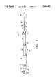
- FIG. 7is a side view of the hub and guidewire/inflation shaft locking device with the guidewire/inflation shaft locking device positioned to lock the guidewire to the hub.
- FIG. 8is a side view of the hub and guidewire/inflation shaft locking device with the guidewire/inflation shaft locking device positioned to lock the inflation shaft to the hub.
- FIG. 9is a cross-sectional view of a telescoping balloon catheter with a second embodiment of the hub and guidewire/inflation shaft locking device of the invention with the guidewire/inflation shaft locking device in an unlocked position.
- FIG. 10is a side view of the second embodiment of the hub and extension member.
- FIG. 11is an end view of the hub and extension member when viewed along line 11--11 in FIG. 10.
- FIG. 12is a side view of the second embodiment of the guidewire/inflation shaft locking device.
- FIG. 13is an end view of the guidewire/inflation shaft locking device when viewed along line 13--13 in FIG. 12.
- FIG. 14is a side view of the second embodiment of the hub and guidewire/inflation shaft locking device with the guidewire/inflation shaft locking device positioned to lock tile guidewire to the hub.
- FIG. 15is a side view of the second embodiment of the hub and guidewire/inflation shaft locking device with the guidewire/inflation shaft locking device positioned to lock the inflation shaft to the hub.
- FIG. 16is a cross-sectional view of a telescoping balloon catheter with a third embodiment of the hub and guidewire/inflation shaft locking device of the invention with the guidewire/inflation shaft locking device in an unlocked position.
- FIG. 17is a side view of the third embodiment of the hub and extension member.
- FIG. 18is an end view of the hub and extension member when viewed along line 18--18 in FIG. 17.
- FIG. 19is a side view of the third embodiment of the guidewire/inflation shaft locking device.
- FIG. 20is an end view of the guidewire/inflation shaft locking device when viewed along line 20--20 in FIG. 19.
- FIG. 21is a side view of the third embodiment of the hub and guidewire/inflation shaft locking device with the guidewire/inflation shaft locking device positioned to lock the guidewire to the hub.
- FIG. 22is a side view of the third embodiment of the hub and guidewire/inflation shaft locking device with the guidewire/inflation shaft locking device positioned to lock the inflation shaft to the hub.
- the hub 10 and guidewire/inflation shaft locking device 20 of the inventionare component parts of a telescoping catheter which is generally designated as 1.
- the telescoping catheter 1also includes an elongated inflation shaft 30, a guidewire shaft 40, an extension shaft 50, a balloon member 59, and telescoping portion 60.
- the elongated inflation shaft 30has an open distal end 32 and an open proximal end 34, and an inflation lumen 36 extending therethrough.
- the inflation shaft 30is formed from stainless steel hypotube in order to lend stiffness and pushability to the catheter 1.
- the inflation shaft 30does not extend for the entire length of catheter 1.
- the extension shaft 50which is substantially shorter than the inflation shaft, has an open distal end 52, an open proximal end 54 and an extension lumen 56 extending therethrough.
- the extension shaft 50is disposed distal to the inflation shaft 30 and the extension lumen 56 is in fluid communication with and extends the inflation lumen 36 through the extent of the extension shaft 50.
- the balloon member 59is disposed at the distal end of extension shaft 50.
- the interior of the balloon member 59is in fluid communication with inflation lumen 36 by way of the extension lumen 56.
- a fitting 15is secured to the proximal end of elongated inflation shaft 30 in a suitable manner.
- the fitting 15is in the form of a female luer fitting.
- the balloon member 59is inflated by injecting inflation fluid through the fitting 15, and subsequently deflated by withdrawing the inflation fluid through the fitting 15.
- the guidewire shaft 40has an open distal end 42 and an open proximal end 44, and a guidewire lumen 46 extending therethrough.
- the guidewire shaft 40is disposed within the extension shaft 50 and extends through balloon member 59.
- the proximal end 44 of the guidewire shaft 40is co-extensive with the proximal end 54 of the extension shaft 50.
- the distal end of balloon member 59is affixed to guidewire shaft 40.
- the distal end of the guidewire shaft 40extends beyond the distal end of the balloon member 59.
- the guidewire lumen 46is sized such that a standard coronary angioplasty guidewire 29 can be slidably received within guidewire lumen 36 (see FIGS. 7 and 8).
- the telescoping portioncan comprise two or more telescoping tubes which are slidably mounted on the inflation shaft 30 and the extension shaft 50.
- the telescoping portion 60comprises a first telescoping tube 70, a second telescoping tube 80 and a third telescoping tube 90, all of which are slidably mounted on the inflation shaft 30 and the extension shaft 50.
- the telescoping tubesare to be formed from a flexible polymer such as polyvinyl chloride, polyethylene, polyethylene terephthalate or, preferably, polyimide.
- the inner diameter of the third telescoping tube 90is greater than the outer diameter of the second telescoping tube 80.
- the inner diameter of the second telescoping tube 80is greater than the outer diameter of the first telescoping tube 70.
- the first telescoping tube 70can be slidably received within the second telescoping tube 80, and both the first and second telescoping tubes 70 and 80, can be slidably received within the third telescoping tube 90.
- the telescoping tubesare relatively thin in thickness so as not to present too much of a discontinuity on the catheter exterior surface.
- a series of stop membersmay be employed to limit the positioning of the first, second and third telescoping tubes along the inflation shaft 30 and the extension shaft 50 so that the distal ends of the second and third telescoping tubes cannot be positioned distal of the distal end of the first telescoping tube.
- a hub 10is affixed to the proximal end of the proximal-most telescoping tube.
- the hub 10is affixed to the proximal end of the third telescoping tube 90.
- the hub 10has a central port 12 through which the inflation shaft 30 and the guidewire 29 are passed (see also FIGS. 2 and 3).
- the guidewire 29will be encased by telescoping portion 60 and guidewire shaft 40 as it extends through the hub 10 to the distal end of the catheter 1.
- the effective "over-the-wire length" of catheter 1may be reduced by withdrawing the inflation shaft 30 proximally from the hub 10.
- the continued proximally-directed withdrawal of the inflation shaft 30causes the first telescoping tube 70 to be fully retracted into the second telescoping tube 80.
- the continued proximally-directed withdrawal of the inflation shaft 30next causes the second telescoping tube 80 and the indwelling first telescoping tube 70 to be fully retracted into the third telescoping tube 90.
- the continued proximally-directed withdrawal of the inflation shaft 30next causes the extension shaft 50 to be retracted into the first telescoping tube 70, which remains located within the second and third telescoping tubes, until the deflated balloon member engages the distal end of the first telescoping tube 70.
- a locking device 20which has a locking lumen 26 extending from the distal end to the proximal end thereof, is slidably mounted on the inflation shaft 30 between the hub 10 and the inflation fitting 15.
- the locking device 20may be formed from a plastic such as polyethylene or polycarbonate or a metal such as stainless steel.
- the locking deviceis formed from Kraton® G-2703, which is a saturated styrene rubber available from the Shell Chemical Company of Houston, Tex.
- the locking device 20may be positioned so as to lock the guidewire 29 to the hub 10 (see FIG. 7) or, alternatively, the locking device 20 may be positioned so as to lock the inflation shaft 30 to the hub 10 (see FIG. 8).
- the locking device 20is sized and shaped so that the distal portion of the locking device 20 can be slidably received within the proximal portion of the central port 12 extending through the hub 10.
- the inner wall 14 of the hub 10, which defines the central port 12is conically-shaped with the diameter of the central port 12 tapering from the proximal end to the distal end of the hub 10.
- the locking device 20is also conically-shaped with the diameter of the outer surface 22 tapering from the proximal end to the distal end of the locking device 20.
- the locking device 20may be slidably inserted into the central port 12 of the hub 10 with the guidewire 29 extending through central port 12 and lying between the inner wall 14 of hub 10 and the outer surface 22 of the locking device 20, so that this interference fit locks the guidewire 29 in a fixed position relative to the hub 10.
- extension member 18is integral with the hub 10 and extends proximally from the proximal end of the hub 10.
- the extension member 18is formed from the same material as the hub 10, and may be formed from plastic, such as polyethylene or polycarbonate, or metal, such as stainless steel. The thickness of the extension member 18 tapers from its distal end to its proximal end.
- the extension member 18supports the locking device 20. Further, the extension member 18 may be engaged with the locking lumen 26 of the locking device 20 so as to lock the inflation shaft 30 in a fixed position relative to the hub 10.
- the distal portion of the locking lumen 26 extending through the locking device 20is sized so that the distal portion of the locking lumen 26 can slide over the proximal portion of the extension member 18.
- the degree of taper of extension member 18is such that the combined thickness of the extension member 18 and the inflation shaft 30 exceeds the diameter of the distal portion of locking lumen 26 at a point proximal of the distal end of extension member 18. At that point there will be an interference fit between the inner wall 28 of locking device 20 that forms locking lumen 26 and the inflation shaft 30 and extension member 18.
- the locking device 20may be slid over the extension member 18 to that point so that the interference fit between inner wall 28 and the inflation shaft 30 and extension member 18 locks the inflation shaft 30 in a fixed position relative to the hub 10.
- a guiding catheter(not shown in Figures) is inserted to the coronary artery in a conventional manner.
- the guidewire 29may be introduced into the telescoping catheter 1 by a back loading technique and then the combination of the telescoping catheter 1 and guidewire is advanced into the guiding catheter.
- the guidewire 29alone is inserted into the guiding catheter and advanced to the site of the stenosis.
- the telescoping portion 60is maneuvered into the fully retracted position so that the effective "over-the-wire length" of the catheter 1 is at a minimum.
- the distal portion of the catheter 1is then loaded onto the proximal portion of the indwelling guidewire 29 in a conventional manner while maintaining the telescoping portion 60 in the fully retracted position.
- the inflation shaft 30is withdrawn through the hub 10 to the maximum extent possible and the deflated balloon member 59 abuts the distal ends of the fully retracted telescoping tubes.
- Locking device 20may be used to lock the inflation shaft 30 in this position relative to the hub 10 by engaging the locking device 20 and the extension member 18 and thereby effectively locking telescoping portion 60 in the fully retracted position. The user is then free to use both hands to load and forwardly advance the telescoping catheter 1 on the guidewire 29 until the proximal end of the guidewire 29 extends beyond the proximal end of the telescoping catheter 1. At that point, the telescoping portion 60 is unlocked by disengaging the locking device 20 from the extension member 18. The telescoping tubes are extended and advanced into the guiding catheter.
- the catheter 1is loaded onto the guidewire 29 and advanced into the guiding catheter under either of the above-described alternative methods, the catheter 1 is maneuvered through the tortuous coronary arteries and along the guidewire until the balloon member 59 is located across the stenosis.
- pressurecan be applied by the use of a hand syringe or another pressurizing device well known in the art (not shown in Figures).
- the inflation of the balloon member 59can be observed if radiographic contrast liquid is used as the inflation fluid. Inflating the balloon member 59 dilates the stenosis by stretching the coronary artery and simultaneously pressing the stenosis into the artery wall.
- the cardiologistwill elect to exchange the indwelling catheter for another catheter with a different sized balloon.
- the guidewireprotrude from the patient's body by a length greater than the length of the dilatation catheter.
- a standard length guidewireis sufficient to effectuate a catheter exchange because the effective "over-the-wire length" of catheter 1 can be reduced by way of the telescoping portion 60.
- the usercan engage the locking device 20 with the central port 12 of the hub 10 to lock the guidewire 29 in a fixed position relative to the hub 10 and across the stenosis.
- the usergrips the fitting 15 and pulls the inflation shaft 30 proximally from the hub 10.
- the continued proximally-directed withdrawal of the inflation shaft 30causes the first telescoping tube 70 to be fully retracted into the second telescoping tube 80.
- the continued proximally-directed withdrawal of the inflation shaft 30next causes the second telescoping tube 80 and the indwelling first telescoping tube 70 to be fully retracted into the third telescoping tube 90.
- the continued proximally-directed withdrawal of the inflation shaft 30next causes the extension shaft 50 to be retracted into the first telescoping tube 70, which remains located within the second and third telescoping tubes, until the deflated balloon member 59 engages the distal end of the first telescoping tube 70.
- the effective "over-the-wire length" of catheter 1will be reduced to the combined length of the third telescoping tube 90 and the balloon member 59.
- the effective "over-the-wire length"may be reduced to about 36 cm.
- the guidewire 29is unlocked from the hub 10 by disengaging the locking device 20 from the central port 12 of tile hub 10.
- the catheter 1With the telescoping portion 60 in the fully retracted position, the catheter 1 is backed-off the guidewire in a conventional manner.
- the telescoping portion 60may be locked in the fully retracted position by engaging the locking device 20 with the extension member 18 to lock the inflation shaft 30 in fixed position relative to the hub 10.
- the minimum effective "over-the-wire" length of catheteris sized to be less than the length of a standard guidewire that protrudes from the patient's body so that an extension wire will not be needed to effect an exchange of catheter 1.
- FIGS. 9-15illustrate a second embodiment of the subject hub and guidewire/inflation shaft locking device.
- the hub 110 and guidewire/inflation shaft locking device 120are component parts of a telescoping catheter 1.
- the hub 110is affixed to the proximal end of the proximal-most telescoping tube. Referring to FIGS. 10 and 11, the hub 110 has a central port 112 through which the inflation shaft 30 and the guidewire 29 are passed.
- the inner wall 114 of the hub 110which defines the central port 112, is conically-shaped with the diameter of the central port 112 tapering from the proximal end to the distal end of the hub 110.
- the inner wall 114 of the hub 110has a groove 113 that extends distally from the proximal end of the hub 110 to point about mid-way to the distal end of the hub 110.
- the radius of the groove 113is sized so that the inflation shaft 30 can be slidably received within the groove 113.
- An extension member 118is integral with the hub 110 and extends proximally from the proximal end of the hub 110.
- the extension member 118includes a securing tail 117 that is disposed at the proximal end of the extension member 118.
- the securing tail 117is triangular-shaped and oriented upwards with respect to the extension member 118.
- the extension member 118 and securing tail 117are formed from the same material as the hub 110, which may be formed from plastic, such as polyethylene or polycarbonate, or metal, such as stainless steel.
- the locking device 120which is generally cylindrically-shaped with a lumen 126 extending from the distal end to the proximal end, is slidably mounted on the extension member 118 between the hub 110 and the securing tail 117 (see FIG. 9).
- a tapered guidewire locking portion 121is disposed at the distal end of the locking device 120.
- the tapered guidewire locking portion 121which is integral with the locking device 120, extends distally from the locking device 120 above the lumen 126.
- the locking device 120 and tapered guidewire locking portion 121may be formed from a plastic material but is preferably formed from the elastomer such as Kraton® G-2703.
- Both the inflation shaft 30 and the guidewire 29pass through the central port 112 in the hub 110.
- the lumen 126 in locking device 120is sized so that when the locking device is slidably mounted on the extension member 118, the inflation shaft 30 extends through the lumen 126 and is slidable therethrough.
- the guidewire 29does not extend through the lumen 126 in locking device 120, but rather extends around the locking device 120. The size and shape of the locking device 120 causes the guidewire 29 to pass over the top of the locking device 120.
- the locking device 120is sized and shaped so that the tapered guidewire locking portion 121 can be slidably received within the proximal portion of the central port 112 extending through hub 110.
- the guidewire locking portion 121is tapered with its thickness decreasing towards its distal end.
- the taper of the outer tapered surface 122 of the guidewire locking portion 121 and the taper of the inner wall 114 of the hub 110result in an interference fit between the outer tapered surface 122 of the locking device 120 and the top portion of the inner wall 114 of the hub 110.
- the locking device 120may be slidably inserted into the central port 112 of the hub 110 with the guidewire 29 extending through central port 112 and lying between the outer tapered surface 122 of the locking device 120 and the top portion of the inner wall 114 of the hub 110, so that this interference fit locks the guidewire 29 in a fixed position relative to the hub 110. Furthermore, the groove 113 in the inner wall 114 of the hub 110 (see FIG. 10) and the size and shape of the locking device 120 ensure that the inflation shaft 30 can be slidably withdrawn through the hub 110 while the guidewire 29 is locked in position.
- the diameter of the lumen 126 through the locking device 120is substantially less than the maximum height of the triangular-shaped securing tail 117.
- the proximal portion of the locking device 120contacts the inclined surface 119 of the triangular-shaped securing tail 117.
- the guidewire locking portion 121is not in contact with the inner wall 114 of the hub 110.
- the securing tail 117is formed from a rigid material and the locking device is formed from a deformable elastomer.
- the proximal portion of the locking device 120 in the vicinity of the lumen 126is somewhat deformed into the shape of the securing tail 117 (see FIG. 15) but an inference fit develops between the inner surface 127 forming lumen 126 through the locking device 120 and the inclined surface 119 of the securing tail 117.
- the inflation shaft 30extends through lumen 126 in locking device 120, the inflation shaft 30 will be between the inner surface 127 forming lumen 126 and the inclined surface 119 of the securing tail 117 so that the interference fit will lock the inflation shaft 30 in a fixed position relative to the hub 110.
- the size of the locking device 120ensures that the guidewire 29 will not be locked in a fixed position simultaneous with the inflation shaft 30 being locked in a fixed position.
- FIGS. 16-22illustrate a third embodiment of the subject hub and guidewire/inflation shaft locking device.
- the hub 210 and guidewire/inflation shaft locking device 220are component parts of a telescoping catheter 1.
- the hub 210is affixed to the proximal end of the proximal-most telescoping tube. Referring to FIGS. 17-18, the hub 210 has a central port 212 through which the inflation shaft 30 and the guidewire 29 are passed. Unlike the previously discussed embodiments, the interior of the hub 210 is not conically-shaped. Rather, the central port 212 is defined by straight bottom wall portion 213 and tapered top wall portion 214. The top wall portion 214 is tapered so that the diameter of central port 212 at the proximal end of the hub 210 is greater than the diameter of the central port 212 at its distal end.
- An extension member 218is integral with the hub 210 and extends proximally from the proximal end of the hub 210.
- the extension member 218includes a securing tail 217 that is disposed at the proximal end of the extension member 218.
- the securing tail 217is triangular-shaped and oriented downwards with respect to the extension member 218.
- the extension member 218 and securing tail 217are formed from the same materials as the hub 210, which may be formed from plastic, such as polyethylene or polycarbonate, or metal, such as stainless steel.
- the locking device 220comprises a cylindrically-shaped sliding member 225 with a lumen 226 extending from the distal end to the proximal end, and a locking member 227 disposed on top of and integral with the sliding member 225.
- the locking member 227includes a tapered guidewire locking portion 221 which extends distally beyond the distal end of the sliding member 225.
- the sliding member 225 and locking member 227may be formed from an elastomer such as Kraton® G-2703.
- the locking device 220is slidably mounted on the extension member 218 between the hub 210 and the securing tail 217.
- Both the inflation shaft 30 and the guidewire 29pass through the central port 212 in the hub 210.
- the lumen 226 in the locking device 220is sized so that when the locking device 220 is slidably mounted on the extension member 118, the inflation shaft 30 extends through the lumen 226 and is slidable therethrough.
- the guidewire 29does not extend through the lumen 226 in locking device 220, but rather extends around the locking device 220. The size and shape of the locking device 220 causes the guidewire 29 to pass over the top of the locking device 220.
- the locking device 220is sized and shaped so that the tapered guidewire locking portion 221 can be slidably received within the proximal portion of the central port 212 extending through hub 210.
- the guidewire locking portion 221is tapered with its thickness decreasing towards the distal end.
- the taper of the outer tapered surface 222 of the guidewire locking portion 221 and the taper of the inner top wall portion 214 of the hub 210result in an interference fit between the outer tapered surface 222 of the locking device 220 and the inner top wall portion 214 of the hub 210.
- the locking device 220may be slidably inserted into the central port 212 of the hub 210 with the guidewire 29 extending through central port 212 and lying between the outer tapered surface 222 of the locking device 220 and the inner top wall portion 214 of the hub 210, so that this interference fit locks the guidewire 29 in a fixed position relative to the hub 210. Furthermore, the size and shape of the locking device 220 ensures that the inflation shaft 30 can be slidably withdrawn through the hub 210 while the guidewire 29 is locked in position.
- the diameter of the lumen 226 through the locking device 220is substantially less than the maximum height of the triangular-shaped securing tail 217.
- the proximal portion of the locking device 220contacts the inclined surface 219 of the triangular-shaped securing tail 217, and an inference fit develops between the inner surface 229 forming lumen 226 through the locking device 220 and the inclined surface 219 of the securing tail 217.
- the inflation shaft 30extends through the lumen 226 in locking device 220, the inflation shaft 30 will lie between the inner surface 229 forming lumen 226 in locking device 220 and the extension member 218 so that the interference fit will lock the inflation shaft 30 in a fixed position relative to the hub 210.
- the size of the locking deviceensures that the guidewire 29 will not be locked in a fixed position simultaneous with the inflation shaft 30 being locked in a fixed position.
Landscapes
- Health & Medical Sciences (AREA)
- Life Sciences & Earth Sciences (AREA)
- Heart & Thoracic Surgery (AREA)
- Anesthesiology (AREA)
- Biophysics (AREA)
- Pulmonology (AREA)
- Engineering & Computer Science (AREA)
- Biomedical Technology (AREA)
- Hematology (AREA)
- Animal Behavior & Ethology (AREA)
- General Health & Medical Sciences (AREA)
- Public Health (AREA)
- Veterinary Medicine (AREA)
- Child & Adolescent Psychology (AREA)
- Vascular Medicine (AREA)
- Media Introduction/Drainage Providing Device (AREA)
Abstract
Description
Claims (19)
Priority Applications (3)
| Application Number | Priority Date | Filing Date | Title |
|---|---|---|---|
| US08/431,546US5658309A (en) | 1995-05-01 | 1995-05-01 | Guidewire/inflation tube locking apparatus and method of use |
| DE69604530TDE69604530T2 (en) | 1995-05-01 | 1996-04-30 | Blocking device for guidewire or inflation hose |
| EP96106824AEP0745409B1 (en) | 1995-05-01 | 1996-04-30 | Guidewire/inflation tube locking apparatus |
Applications Claiming Priority (1)
| Application Number | Priority Date | Filing Date | Title |
|---|---|---|---|
| US08/431,546US5658309A (en) | 1995-05-01 | 1995-05-01 | Guidewire/inflation tube locking apparatus and method of use |
Publications (1)
| Publication Number | Publication Date |
|---|---|
| US5658309Atrue US5658309A (en) | 1997-08-19 |
Family
ID=23712417
Family Applications (1)
| Application Number | Title | Priority Date | Filing Date |
|---|---|---|---|
| US08/431,546Expired - Fee RelatedUS5658309A (en) | 1995-05-01 | 1995-05-01 | Guidewire/inflation tube locking apparatus and method of use |
Country Status (3)
| Country | Link |
|---|---|
| US (1) | US5658309A (en) |
| EP (1) | EP0745409B1 (en) |
| DE (1) | DE69604530T2 (en) |
Cited By (60)
| Publication number | Priority date | Publication date | Assignee | Title |
|---|---|---|---|---|
| US5911752A (en)* | 1996-09-13 | 1999-06-15 | Intratherapeutics, Inc. | Method for collapsing a stent |
| US6027474A (en)* | 1998-09-30 | 2000-02-22 | Medtronic Ave, Inc. | Hydraulic exchange catheter |
| US6053313A (en)* | 1996-10-25 | 2000-04-25 | Ave Connaught | Catheter packaging system |
| US6099496A (en)* | 1998-09-30 | 2000-08-08 | Medtronic Ave, Inc. | Catheter having a variable length shaft segment and method of use |
| US6200305B1 (en) | 1998-09-30 | 2001-03-13 | Medtronic Ave, Inc. | Catheter having a variable length shaft segment and method of use |
| US6312407B1 (en) | 1995-06-05 | 2001-11-06 | Medtronic Percusurge, Inc. | Occlusion of a vessel |
| US20020143361A1 (en)* | 2001-04-03 | 2002-10-03 | Nareak Douk | Temporary device for capturing embolic material |
| US6605075B1 (en)* | 1999-12-21 | 2003-08-12 | Ethicon, Inc. | Flushable hub |
| US6641563B1 (en)* | 2000-11-01 | 2003-11-04 | Arrow International, Inc. | Stylet-free epidural catheter and thread assist device |
| US6682499B2 (en)* | 2001-06-28 | 2004-01-27 | Jay Alan Lenker | Method and apparatus for venous drainage and retrograde coronary perfusion |
| US20050090835A1 (en)* | 2003-07-31 | 2005-04-28 | Deal Stephen E. | Wire guide holder |
| US6994689B1 (en) | 1995-06-05 | 2006-02-07 | Medtronic Vascular, Inc. | Occlusion of a vessel |
| US20060195117A1 (en)* | 2003-07-31 | 2006-08-31 | Rucker Brian K | Wire guide holder with wire guide deflector |
| US20060212022A1 (en)* | 2005-03-21 | 2006-09-21 | Boston Scientific Scimed,Inc. | Tissue approximation device |
| US20070083219A1 (en)* | 2005-10-12 | 2007-04-12 | Buiser Marcia S | Embolic coil introducer sheath locking mechanisms |
| US20070219617A1 (en)* | 2006-03-17 | 2007-09-20 | Sean Saint | Handle for Long Self Expanding Stent |
| JP2010227579A (en)* | 2009-03-27 | 2010-10-14 | Circulite Inc | Transseptal cannula device, coaxial balloon delivery device, and method of using the same |
| US20110263977A1 (en)* | 2003-03-28 | 2011-10-27 | Nash John E | Catheter with associated extension lumen |
| US20140088560A1 (en)* | 2011-03-30 | 2014-03-27 | Cornell University | Intra-luminal access apparatus and methods of using the same |
| US9561345B2 (en) | 2013-12-23 | 2017-02-07 | Route 92 Medical, Inc. | Methods and systems for treatment of acute ischemic stroke |
| US9681882B2 (en) | 2014-03-21 | 2017-06-20 | Route 92 Medical, Inc. | Rapid aspiration thrombectomy system and method |
| US20180126121A1 (en)* | 2016-11-09 | 2018-05-10 | Medtronic Vascular, Inc. | Telescoping catheter |
| US20180161541A1 (en)* | 2016-12-08 | 2018-06-14 | Sanford Health | Slide Guide Catheter and Methods for Use Thereof |
| US10080874B2 (en) | 2015-04-09 | 2018-09-25 | Boston Scientific Scimed, Inc. | Trap balloon catheter with trap balloon retainer |
| US10130798B2 (en) | 2013-07-15 | 2018-11-20 | John P. Pigott | Balloon catheter having a retractable sheath and locking mechanism |
| US10315014B2 (en) | 2013-07-15 | 2019-06-11 | John P. Pigott | Balloon catheter having a retractable sheath and locking mechanism with balloon recapture element |
| US10327790B2 (en) | 2011-08-05 | 2019-06-25 | Route 92 Medical, Inc. | Methods and systems for treatment of acute ischemic stroke |
| US10426497B2 (en) | 2015-07-24 | 2019-10-01 | Route 92 Medical, Inc. | Anchoring delivery system and methods |
| US10448972B2 (en)* | 2015-09-15 | 2019-10-22 | Custom Medical Applications Inc. | Deployment devices and related assemblies and methods |
| US10456555B2 (en) | 2015-02-04 | 2019-10-29 | Route 92 Medical, Inc. | Rapid aspiration thrombectomy system and method |
| USD865165S1 (en) | 2013-11-25 | 2019-10-29 | Custom Medical Applications, Inc. | Medical device anchor |
| US10485572B2 (en) | 2011-09-13 | 2019-11-26 | John P. Pigott | Intravascular catheter having an expandable incising portion |
| US10603069B2 (en) | 2015-01-13 | 2020-03-31 | John P. Pigott | Intravascular catheter balloon device having a tool for atherectomy or an incising portion for atheromatous plaque scoring |
| US10610255B2 (en) | 2011-09-13 | 2020-04-07 | John P. Pigott | Intravascular catheter having an expandable incising portion and medication delivery system |
| US10779855B2 (en) | 2011-08-05 | 2020-09-22 | Route 92 Medical, Inc. | Methods and systems for treatment of acute ischemic stroke |
| US10799669B2 (en) | 2017-01-20 | 2020-10-13 | Route 92 Medical, Inc. | Single operator intracranial medical device delivery systems and methods of use |
| US10828471B2 (en) | 2013-07-15 | 2020-11-10 | John P. Pigott | Balloon catheter having a retractable sheath |
| CN112041015A (en)* | 2018-03-01 | 2020-12-04 | 史密斯医疗Asd公司 | Guide wire holding device |
| US10946177B2 (en) | 2018-12-19 | 2021-03-16 | Teleflex Life Sciences Limited | Guide extension catheter |
| US10974028B2 (en) | 2015-05-26 | 2021-04-13 | Teleflex Life Sciences Limited | Guidewire fixation |
| US11020133B2 (en) | 2017-01-10 | 2021-06-01 | Route 92 Medical, Inc. | Aspiration catheter systems and methods of use |
| US11033712B2 (en) | 2015-01-13 | 2021-06-15 | Venturemed Group, Inc. | Intravascular catheter having an expandable portion |
| US11065019B1 (en) | 2015-02-04 | 2021-07-20 | Route 92 Medical, Inc. | Aspiration catheter systems and methods of use |
| US11147699B2 (en) | 2015-07-24 | 2021-10-19 | Route 92 Medical, Inc. | Methods of intracerebral implant delivery |
| US11202892B2 (en) | 2013-07-15 | 2021-12-21 | John P. Pigott | Balloon catheter having a retractable sheath |
| US11229770B2 (en) | 2018-05-17 | 2022-01-25 | Route 92 Medical, Inc. | Aspiration catheter systems and methods of use |
| US11253680B2 (en) | 2016-05-03 | 2022-02-22 | Cook Medical Technologies Llc | Wire lock assembly |
| CN114376492A (en)* | 2020-10-06 | 2022-04-22 | 奥林巴斯株式会社 | Suppression device, suppression method, endoscopic treatment instrument, and endoscopic treatment system |
| US11357533B2 (en) | 2011-09-13 | 2022-06-14 | Venturemed Group, Inc. | Intravascular catheter having an expandable incising portion and abrasive surfaces |
| US11413062B2 (en) | 2011-09-13 | 2022-08-16 | Venturemed Group, Inc. | Methods for preparing a zone of attention within a vascular system for subsequent angioplasty with an intravascular catheter device having an expandable incising portion and an integrated embolic protection device |
| US11559663B2 (en)* | 2018-06-05 | 2023-01-24 | Medtronic Vascular, Inc. | Catheter including slidable push grip |
| US11559325B2 (en) | 2011-09-13 | 2023-01-24 | Venturemed Group, Inc. | Intravascular catheter having an expandable incising portion and grating tool |
| US11576698B2 (en) | 2011-09-13 | 2023-02-14 | Venturemed Group, Inc. | Intravascular catheter device for improved angioplasty |
| US20230355206A1 (en)* | 2022-05-06 | 2023-11-09 | Boston Scientific Scimed, Inc. | Intravascular Imaging Devices |
| WO2023240937A1 (en)* | 2022-06-14 | 2023-12-21 | 上海腾复医疗科技有限公司 | Multifunctional thrombus removal apparatus |
| WO2024044080A1 (en)* | 2021-08-27 | 2024-02-29 | Surmodics Md, Llc | Catheter locking mechanisms and methods for same |
| US12096955B2 (en) | 2017-02-24 | 2024-09-24 | Venturemed Group, Inc. | Intravascular catheter having an expandable incising portion and abrasive surfaces |
| US12144940B2 (en) | 2020-10-09 | 2024-11-19 | Route 92 Medical, Inc. | Aspiration catheter systems and methods of use |
| US12324603B2 (en) | 2011-09-13 | 2025-06-10 | Venturemed Group, Inc. | Intravascular catheter having an expandable incising portion |
| US12408932B2 (en) | 2022-03-23 | 2025-09-09 | Venturemed Group, Inc. | Intravascular device having feedback elements |
Families Citing this family (15)
| Publication number | Priority date | Publication date | Assignee | Title |
|---|---|---|---|---|
| US5807330A (en)* | 1996-12-16 | 1998-09-15 | University Of Southern California | Angioplasty catheter |
| US6050949A (en)* | 1997-09-22 | 2000-04-18 | Scimed Life Systems, Inc. | Catheher system having connectable distal and proximal portions |
| BG102366A (en)* | 1998-04-02 | 1999-10-29 | A.I.Stefanov Medical Research Inc. | Canal with alternating length and form |
| US6117140A (en)* | 1998-06-26 | 2000-09-12 | Scimed Life Systems, Inc. | Stent delivery device |
| US8211087B2 (en) | 2003-07-31 | 2012-07-03 | Cook Medical Technologies Llc | Distal wire stop |
| JP4758985B2 (en)* | 2004-04-21 | 2011-08-31 | ウィルソン−クック・メディカル・インコーポレーテッド | Distal wire stop device |
| PT2407201E (en) | 2004-10-25 | 2014-08-28 | Coloplast As | Male telescope catheter |
| US7905823B2 (en) | 2006-08-30 | 2011-03-15 | Circulite, Inc. | Devices, methods and systems for establishing supplemental blood flow in the circulatory system |
| EP2650029B1 (en) | 2006-08-30 | 2015-01-14 | CircuLite, Inc. | Devices and systems for establishing supplemental blood flow in the circulatory system |
| US8333686B2 (en) | 2006-08-30 | 2012-12-18 | Circulite, Inc. | Cannula insertion devices, systems, and methods including a compressible member |
| US7922696B2 (en) | 2007-01-24 | 2011-04-12 | Access Scientific, Inc. | Access device |
| EP3093038B1 (en) | 2007-04-18 | 2019-05-22 | Access Scientific, Inc. | Access device |
| US8292872B2 (en) | 2007-06-29 | 2012-10-23 | Cook Medical Technologies Llc | Distal wire stop having adjustable handle |
| DE202015002060U1 (en)* | 2015-03-17 | 2015-11-25 | Gerhard-Friedrich Horak | Infusion and aspiration catheter (IAC) (catheter for removal of thrombi and application of drugs) |
| US11027099B2 (en) | 2015-04-30 | 2021-06-08 | Smiths Medical Asd, Inc. | Vascular access device |
Citations (11)
| Publication number | Priority date | Publication date | Assignee | Title |
|---|---|---|---|---|
| US4860742A (en)* | 1988-05-16 | 1989-08-29 | Medical Innovations Corporation | Assembly of wire inserter and lock for a medical wire |
| US5040548A (en)* | 1989-06-01 | 1991-08-20 | Yock Paul G | Angioplasty mehtod |
| WO1992006733A1 (en)* | 1990-10-19 | 1992-04-30 | Trustees Of Boston University | Percutaneous transseptal left atrial cannulation system |
| US5203774A (en)* | 1990-01-30 | 1993-04-20 | C. R. Bard Ireland Limited | Device for use with a catheter |
| WO1993011750A1 (en)* | 1991-12-17 | 1993-06-24 | Fuisz Technologies Ltd. | Ulcer prevention and treatment composition and method |
| US5269759A (en)* | 1992-07-28 | 1993-12-14 | Cordis Corporation | Magnetic guidewire coupling for vascular dilatation apparatus |
| US5334160A (en)* | 1992-05-04 | 1994-08-02 | Scimed Life Systems, Inc. | Intravascular catheter with sleeve and method for use thereof |
| US5387193A (en)* | 1994-02-09 | 1995-02-07 | Baxter International Inc. | Balloon dilation catheter with hypotube |
| US5388590A (en)* | 1993-07-28 | 1995-02-14 | Medtronic, Inc. | Catheter exchange device |
| US5484409A (en)* | 1989-08-25 | 1996-01-16 | Scimed Life Systems, Inc. | Intravascular catheter and method for use thereof |
| US5507300A (en)* | 1993-10-06 | 1996-04-16 | Sherwood Medical Company | Guide wire feeding device |
- 1995
- 1995-05-01USUS08/431,546patent/US5658309A/ennot_activeExpired - Fee Related
- 1996
- 1996-04-30EPEP96106824Apatent/EP0745409B1/ennot_activeExpired - Lifetime
- 1996-04-30DEDE69604530Tpatent/DE69604530T2/ennot_activeExpired - Fee Related
Patent Citations (11)
| Publication number | Priority date | Publication date | Assignee | Title |
|---|---|---|---|---|
| US4860742A (en)* | 1988-05-16 | 1989-08-29 | Medical Innovations Corporation | Assembly of wire inserter and lock for a medical wire |
| US5040548A (en)* | 1989-06-01 | 1991-08-20 | Yock Paul G | Angioplasty mehtod |
| US5484409A (en)* | 1989-08-25 | 1996-01-16 | Scimed Life Systems, Inc. | Intravascular catheter and method for use thereof |
| US5203774A (en)* | 1990-01-30 | 1993-04-20 | C. R. Bard Ireland Limited | Device for use with a catheter |
| WO1992006733A1 (en)* | 1990-10-19 | 1992-04-30 | Trustees Of Boston University | Percutaneous transseptal left atrial cannulation system |
| WO1993011750A1 (en)* | 1991-12-17 | 1993-06-24 | Fuisz Technologies Ltd. | Ulcer prevention and treatment composition and method |
| US5334160A (en)* | 1992-05-04 | 1994-08-02 | Scimed Life Systems, Inc. | Intravascular catheter with sleeve and method for use thereof |
| US5269759A (en)* | 1992-07-28 | 1993-12-14 | Cordis Corporation | Magnetic guidewire coupling for vascular dilatation apparatus |
| US5388590A (en)* | 1993-07-28 | 1995-02-14 | Medtronic, Inc. | Catheter exchange device |
| US5507300A (en)* | 1993-10-06 | 1996-04-16 | Sherwood Medical Company | Guide wire feeding device |
| US5387193A (en)* | 1994-02-09 | 1995-02-07 | Baxter International Inc. | Balloon dilation catheter with hypotube |
Cited By (126)
| Publication number | Priority date | Publication date | Assignee | Title |
|---|---|---|---|---|
| US6994689B1 (en) | 1995-06-05 | 2006-02-07 | Medtronic Vascular, Inc. | Occlusion of a vessel |
| US6312407B1 (en) | 1995-06-05 | 2001-11-06 | Medtronic Percusurge, Inc. | Occlusion of a vessel |
| US5911752A (en)* | 1996-09-13 | 1999-06-15 | Intratherapeutics, Inc. | Method for collapsing a stent |
| US6053313A (en)* | 1996-10-25 | 2000-04-25 | Ave Connaught | Catheter packaging system |
| US6027474A (en)* | 1998-09-30 | 2000-02-22 | Medtronic Ave, Inc. | Hydraulic exchange catheter |
| US6099496A (en)* | 1998-09-30 | 2000-08-08 | Medtronic Ave, Inc. | Catheter having a variable length shaft segment and method of use |
| US6200305B1 (en) | 1998-09-30 | 2001-03-13 | Medtronic Ave, Inc. | Catheter having a variable length shaft segment and method of use |
| US6605075B1 (en)* | 1999-12-21 | 2003-08-12 | Ethicon, Inc. | Flushable hub |
| US6641563B1 (en)* | 2000-11-01 | 2003-11-04 | Arrow International, Inc. | Stylet-free epidural catheter and thread assist device |
| US20020143361A1 (en)* | 2001-04-03 | 2002-10-03 | Nareak Douk | Temporary device for capturing embolic material |
| US7044958B2 (en)* | 2001-04-03 | 2006-05-16 | Medtronic Vascular, Inc. | Temporary device for capturing embolic material |
| US6682499B2 (en)* | 2001-06-28 | 2004-01-27 | Jay Alan Lenker | Method and apparatus for venous drainage and retrograde coronary perfusion |
| US8251978B2 (en)* | 2003-03-28 | 2012-08-28 | Kensey Nash Corporation | Catheter with associated extension lumen |
| US20110263977A1 (en)* | 2003-03-28 | 2011-10-27 | Nash John E | Catheter with associated extension lumen |
| US8523801B2 (en) | 2003-03-28 | 2013-09-03 | Kensey Nash Corporation | Catheter with associated extension lumen |
| US20050090835A1 (en)* | 2003-07-31 | 2005-04-28 | Deal Stephen E. | Wire guide holder |
| US7637863B2 (en) | 2003-07-31 | 2009-12-29 | Wilson-Cook Medical Inc. | Wire guide holder |
| US20060195117A1 (en)* | 2003-07-31 | 2006-08-31 | Rucker Brian K | Wire guide holder with wire guide deflector |
| US7708715B2 (en)* | 2005-03-21 | 2010-05-04 | Boston Scientific Scimed, Inc. | Tissue approximation device |
| US20060212022A1 (en)* | 2005-03-21 | 2006-09-21 | Boston Scientific Scimed,Inc. | Tissue approximation device |
| US20070083219A1 (en)* | 2005-10-12 | 2007-04-12 | Buiser Marcia S | Embolic coil introducer sheath locking mechanisms |
| US20070219617A1 (en)* | 2006-03-17 | 2007-09-20 | Sean Saint | Handle for Long Self Expanding Stent |
| JP2010227579A (en)* | 2009-03-27 | 2010-10-14 | Circulite Inc | Transseptal cannula device, coaxial balloon delivery device, and method of using the same |
| JP2014176720A (en)* | 2009-03-27 | 2014-09-25 | Circulite Inc | Transseptal cannula device, coaxial balloon delivery device, and method of using the same |
| US9028393B2 (en) | 2009-03-27 | 2015-05-12 | Circulite, Inc. | Coaxial balloon delivery device and method of delivering a transseptal cannula to a heart |
| US20140088560A1 (en)* | 2011-03-30 | 2014-03-27 | Cornell University | Intra-luminal access apparatus and methods of using the same |
| US11871944B2 (en) | 2011-08-05 | 2024-01-16 | Route 92 Medical, Inc. | Methods and systems for treatment of acute ischemic stroke |
| US10779855B2 (en) | 2011-08-05 | 2020-09-22 | Route 92 Medical, Inc. | Methods and systems for treatment of acute ischemic stroke |
| US10743893B2 (en) | 2011-08-05 | 2020-08-18 | Route 92 Medical, Inc. | Methods and systems for treatment of acute ischemic stroke |
| US10722251B2 (en) | 2011-08-05 | 2020-07-28 | Route 92 Medical, Inc. | Methods and systems for treatment of acute ischemic stroke |
| US12343036B2 (en) | 2011-08-05 | 2025-07-01 | Route 92 Medical, Inc. | Methods and systems for treatment of acute ischemic stroke |
| US10327790B2 (en) | 2011-08-05 | 2019-06-25 | Route 92 Medical, Inc. | Methods and systems for treatment of acute ischemic stroke |
| US10646239B2 (en) | 2011-08-05 | 2020-05-12 | Route 92 Medical, Inc. | Methods and systems for treatment of acute ischemic stroke |
| US12262911B2 (en) | 2011-08-05 | 2025-04-01 | Route 92 Medical, Inc. | Methods and systems for treatment of acute ischemic stroke |
| US11357533B2 (en) | 2011-09-13 | 2022-06-14 | Venturemed Group, Inc. | Intravascular catheter having an expandable incising portion and abrasive surfaces |
| US11571239B2 (en) | 2011-09-13 | 2023-02-07 | Venturemed Group, Inc. | Intravascular catheter having an expandable incising portion and medication delivery system |
| US12324603B2 (en) | 2011-09-13 | 2025-06-10 | Venturemed Group, Inc. | Intravascular catheter having an expandable incising portion |
| US10939936B2 (en) | 2011-09-13 | 2021-03-09 | Venturemed Group, Inc. | Intravascular catheter with incising devices |
| US12185968B2 (en) | 2011-09-13 | 2025-01-07 | Venturemed Group, Inc. | Intravascular catheter having an expandable incising portion |
| US11331118B2 (en) | 2011-09-13 | 2022-05-17 | Venturemed Group, Inc. | Intravascular catheter having an expandable incising portion |
| US11413062B2 (en) | 2011-09-13 | 2022-08-16 | Venturemed Group, Inc. | Methods for preparing a zone of attention within a vascular system for subsequent angioplasty with an intravascular catheter device having an expandable incising portion and an integrated embolic protection device |
| US11559325B2 (en) | 2011-09-13 | 2023-01-24 | Venturemed Group, Inc. | Intravascular catheter having an expandable incising portion and grating tool |
| US10485572B2 (en) | 2011-09-13 | 2019-11-26 | John P. Pigott | Intravascular catheter having an expandable incising portion |
| US10485570B2 (en) | 2011-09-13 | 2019-11-26 | John P. Pigott | Intravascular catheter having a cantilevered expandable incising portion |
| US11576698B2 (en) | 2011-09-13 | 2023-02-14 | Venturemed Group, Inc. | Intravascular catheter device for improved angioplasty |
| US11123097B2 (en) | 2011-09-13 | 2021-09-21 | Venturemed Group, Inc. | Intravascular catheter having an expandable incising portion |
| US10610255B2 (en) | 2011-09-13 | 2020-04-07 | John P. Pigott | Intravascular catheter having an expandable incising portion and medication delivery system |
| US10130798B2 (en) | 2013-07-15 | 2018-11-20 | John P. Pigott | Balloon catheter having a retractable sheath and locking mechanism |
| US10315014B2 (en) | 2013-07-15 | 2019-06-11 | John P. Pigott | Balloon catheter having a retractable sheath and locking mechanism with balloon recapture element |
| US11154694B2 (en) | 2013-07-15 | 2021-10-26 | John P. Pigott | Balloon catheter having a retractable sheath and locking mechanism with balloon recapture element |
| US11154693B2 (en) | 2013-07-15 | 2021-10-26 | John P. Pigott | Balloon catheter having a retractable sheath |
| US10828471B2 (en) | 2013-07-15 | 2020-11-10 | John P. Pigott | Balloon catheter having a retractable sheath |
| US11202892B2 (en) | 2013-07-15 | 2021-12-21 | John P. Pigott | Balloon catheter having a retractable sheath |
| USD865165S1 (en) | 2013-11-25 | 2019-10-29 | Custom Medical Applications, Inc. | Medical device anchor |
| US10471233B2 (en) | 2013-12-23 | 2019-11-12 | Route 92 Medical, Inc. | Methods and systems for treatment of acute ischemic stroke |
| US11534575B2 (en) | 2013-12-23 | 2022-12-27 | Route 92 Medical, Inc. | Methods and systems for treatment of acute ischemic stroke |
| US10213582B2 (en) | 2013-12-23 | 2019-02-26 | Route 92 Medical, Inc. | Methods and systems for treatment of acute ischemic stroke |
| US12115320B2 (en) | 2013-12-23 | 2024-10-15 | Route 92 Medical, Inc. | Methods and systems for treatment of acute ischemic stroke |
| US9561345B2 (en) | 2013-12-23 | 2017-02-07 | Route 92 Medical, Inc. | Methods and systems for treatment of acute ischemic stroke |
| US10569049B2 (en) | 2013-12-23 | 2020-02-25 | Route 92 Medical, Inc. | Methods and systems for treatment of acute ischemic stroke |
| US11318282B2 (en) | 2013-12-23 | 2022-05-03 | Route 92 Medical, Inc. | Methods and systems for treatment of acute ischemic stroke |
| US10864351B2 (en) | 2013-12-23 | 2020-12-15 | Route 92 Medical, Inc. | Methods and systems for treatment of acute ischemic stroke |
| US12343480B2 (en) | 2013-12-23 | 2025-07-01 | Route 92 Medical, Inc. | Methods and systems for treatment of acute ischemic stroke |
| US9820761B2 (en) | 2014-03-21 | 2017-11-21 | Route 92 Medical, Inc. | Rapid aspiration thrombectomy system and method |
| US9681882B2 (en) | 2014-03-21 | 2017-06-20 | Route 92 Medical, Inc. | Rapid aspiration thrombectomy system and method |
| US11033712B2 (en) | 2015-01-13 | 2021-06-15 | Venturemed Group, Inc. | Intravascular catheter having an expandable portion |
| US10603069B2 (en) | 2015-01-13 | 2020-03-31 | John P. Pigott | Intravascular catheter balloon device having a tool for atherectomy or an incising portion for atheromatous plaque scoring |
| US11850376B2 (en) | 2015-01-13 | 2023-12-26 | Venturemed Group, Inc. | Intravascular catheter having an expandable portion |
| US11185664B2 (en) | 2015-02-04 | 2021-11-30 | Route 92 Medical, Inc. | Rapid aspiration thrombectomy system and method |
| US11633570B2 (en) | 2015-02-04 | 2023-04-25 | Route 92 Medical, Inc. | Rapid aspiration thrombectomy system and method |
| US10485952B2 (en) | 2015-02-04 | 2019-11-26 | Route 92 Medical, Inc. | Rapid aspiration thrombectomy system and method |
| US11224721B2 (en) | 2015-02-04 | 2022-01-18 | Route 92 Medical, Inc. | Rapid aspiration thrombectomy system and method |
| US11224450B2 (en) | 2015-02-04 | 2022-01-18 | Route 92 Medical, Inc. | Aspiration catheter systems and methods of use |
| US11576691B2 (en) | 2015-02-04 | 2023-02-14 | Route 92 Medical, Inc. | Aspiration catheter systems and methods of use |
| US11065019B1 (en) | 2015-02-04 | 2021-07-20 | Route 92 Medical, Inc. | Aspiration catheter systems and methods of use |
| US10456555B2 (en) | 2015-02-04 | 2019-10-29 | Route 92 Medical, Inc. | Rapid aspiration thrombectomy system and method |
| US11305094B2 (en) | 2015-02-04 | 2022-04-19 | Route 92 Medical, Inc. | Rapid aspiration thrombectomy system and method |
| US11633571B2 (en) | 2015-02-04 | 2023-04-25 | Route 92 Medical, Inc. | Rapid aspiration thrombectomy system and method |
| US11793972B2 (en) | 2015-02-04 | 2023-10-24 | Route 92 Medical, Inc. | Rapid aspiration thrombectomy system and method |
| US11793529B2 (en) | 2015-02-04 | 2023-10-24 | Route 92 Medical, Inc. | Aspiration catheter systems and methods of use |
| US11806032B2 (en) | 2015-02-04 | 2023-11-07 | Route 92 Medical, Inc. | Aspiration catheter systems and methods of use |
| US11383064B2 (en) | 2015-02-04 | 2022-07-12 | Route 92 Medical, Inc. | Rapid aspiration thrombectomy system and method |
| US11395903B2 (en) | 2015-02-04 | 2022-07-26 | Route 92 Medical, Inc. | Rapid aspiration thrombectomy system and method |
| US10080874B2 (en) | 2015-04-09 | 2018-09-25 | Boston Scientific Scimed, Inc. | Trap balloon catheter with trap balloon retainer |
| US11013894B2 (en) | 2015-04-09 | 2021-05-25 | Boston Scientific Scimed, Inc. | Trap balloon catheter with trap balloon retainer |
| US12337125B2 (en) | 2015-05-26 | 2025-06-24 | Teleflex Life Sciences Llc | Guidewire fixation |
| US10974028B2 (en) | 2015-05-26 | 2021-04-13 | Teleflex Life Sciences Limited | Guidewire fixation |
| US10426497B2 (en) | 2015-07-24 | 2019-10-01 | Route 92 Medical, Inc. | Anchoring delivery system and methods |
| US12213688B2 (en) | 2015-07-24 | 2025-02-04 | Route 92 Medical, Inc. | Anchoring delivery system and methods |
| US11998468B2 (en) | 2015-07-24 | 2024-06-04 | Route 92 Medical, Inc. | Methods of intracerebral implant delivery |
| US11224449B2 (en) | 2015-07-24 | 2022-01-18 | Route 92 Medical, Inc. | Anchoring delivery system and methods |
| US11147699B2 (en) | 2015-07-24 | 2021-10-19 | Route 92 Medical, Inc. | Methods of intracerebral implant delivery |
| US10448972B2 (en)* | 2015-09-15 | 2019-10-22 | Custom Medical Applications Inc. | Deployment devices and related assemblies and methods |
| US11918250B2 (en) | 2015-09-15 | 2024-03-05 | Custom Medical Applications, Inc. | Deployment devices and related methods |
| US11253680B2 (en) | 2016-05-03 | 2022-02-22 | Cook Medical Technologies Llc | Wire lock assembly |
| US11944767B2 (en) | 2016-05-03 | 2024-04-02 | Cook Medical Technologies Llc | Wire lock assembly |
| US12408942B2 (en) | 2016-07-01 | 2025-09-09 | Venturemed Group, Inc. | Intravascular catheter having an expandable incising portion and embolic protection device |
| US12233221B2 (en) | 2016-11-09 | 2025-02-25 | Medtronic Vascular, Inc. | Telescoping catheter |
| US20180126121A1 (en)* | 2016-11-09 | 2018-05-10 | Medtronic Vascular, Inc. | Telescoping catheter |
| US10869991B2 (en)* | 2016-11-09 | 2020-12-22 | Medtronic Vascular, Inc. | Telescoping catheter |
| US11027093B2 (en)* | 2016-12-08 | 2021-06-08 | Sanford Health | Slide guide catheter and methods for use thereof |
| US11801363B2 (en) | 2016-12-08 | 2023-10-31 | Sanford Health | Slide guide catheter and methods for use thereof |
| US20180161541A1 (en)* | 2016-12-08 | 2018-06-14 | Sanford Health | Slide Guide Catheter and Methods for Use Thereof |
| US11020133B2 (en) | 2017-01-10 | 2021-06-01 | Route 92 Medical, Inc. | Aspiration catheter systems and methods of use |
| US12295595B2 (en) | 2017-01-10 | 2025-05-13 | Route 92 Medical, Inc. | Aspiration catheter systems and methods of use |
| US11399852B2 (en) | 2017-01-10 | 2022-08-02 | Route 92 Medical, Inc. | Aspiration catheter systems and methods of use |
| US12194247B2 (en) | 2017-01-20 | 2025-01-14 | Route 92 Medical, Inc. | Single operator intracranial medical device delivery systems and methods of use |
| US10864350B2 (en) | 2017-01-20 | 2020-12-15 | Route 92 Medical, Inc. | Single operator intracranial medical device delivery systems and methods of use |
| US10799669B2 (en) | 2017-01-20 | 2020-10-13 | Route 92 Medical, Inc. | Single operator intracranial medical device delivery systems and methods of use |
| US12096955B2 (en) | 2017-02-24 | 2024-09-24 | Venturemed Group, Inc. | Intravascular catheter having an expandable incising portion and abrasive surfaces |
| CN112041015B (en)* | 2018-03-01 | 2022-10-04 | 史密斯医疗Asd公司 | Guide wire holding device |
| CN112041015A (en)* | 2018-03-01 | 2020-12-04 | 史密斯医疗Asd公司 | Guide wire holding device |
| US11738179B2 (en) | 2018-03-01 | 2023-08-29 | Smiths Medical Asd, Inc. | Guidewire retention device |
| US11229770B2 (en) | 2018-05-17 | 2022-01-25 | Route 92 Medical, Inc. | Aspiration catheter systems and methods of use |
| US11607523B2 (en) | 2018-05-17 | 2023-03-21 | Route 92 Medical, Inc. | Aspiration catheter systems and methods of use |
| US12383702B2 (en) | 2018-05-17 | 2025-08-12 | Route 92 Medical, Inc. | Aspiration catheter systems and methods of use |
| US11925770B2 (en) | 2018-05-17 | 2024-03-12 | Route 92 Medical, Inc. | Aspiration catheter systems and methods of use |
| US11559663B2 (en)* | 2018-06-05 | 2023-01-24 | Medtronic Vascular, Inc. | Catheter including slidable push grip |
| US10946177B2 (en) | 2018-12-19 | 2021-03-16 | Teleflex Life Sciences Limited | Guide extension catheter |
| CN114376492A (en)* | 2020-10-06 | 2022-04-22 | 奥林巴斯株式会社 | Suppression device, suppression method, endoscopic treatment instrument, and endoscopic treatment system |
| US12144940B2 (en) | 2020-10-09 | 2024-11-19 | Route 92 Medical, Inc. | Aspiration catheter systems and methods of use |
| US12433633B2 (en) | 2021-04-02 | 2025-10-07 | Venturemed Group, Inc. | Intravascular catheter having an expandable incising portion |
| WO2024044080A1 (en)* | 2021-08-27 | 2024-02-29 | Surmodics Md, Llc | Catheter locking mechanisms and methods for same |
| US12408932B2 (en) | 2022-03-23 | 2025-09-09 | Venturemed Group, Inc. | Intravascular device having feedback elements |
| US20230355206A1 (en)* | 2022-05-06 | 2023-11-09 | Boston Scientific Scimed, Inc. | Intravascular Imaging Devices |
| WO2023240937A1 (en)* | 2022-06-14 | 2023-12-21 | 上海腾复医疗科技有限公司 | Multifunctional thrombus removal apparatus |
Also Published As
| Publication number | Publication date |
|---|---|
| EP0745409A1 (en) | 1996-12-04 |
| DE69604530D1 (en) | 1999-11-11 |
| DE69604530T2 (en) | 2000-05-11 |
| EP0745409B1 (en) | 1999-10-06 |
Similar Documents
| Publication | Publication Date | Title |
|---|---|---|
| US5658309A (en) | Guidewire/inflation tube locking apparatus and method of use | |
| US5846259A (en) | Telescoping catheter and method of use | |
| US6251084B1 (en) | Guide catheter and guidewires for effecting rapid catheter exchange | |
| US5328469A (en) | Hybrid balloon angioplasty catheter and methods of use | |
| US5409459A (en) | Windowed catheter and method of use | |
| US6200305B1 (en) | Catheter having a variable length shaft segment and method of use | |
| US5941871A (en) | Catheter systems with interchangeable parts | |
| US5507768A (en) | Stent delivery system | |
| US5706827A (en) | Magnetic lumen catheter | |
| US5281200A (en) | Multiple component balloon catheter system and stenosis treatment procedure | |
| US5163903A (en) | Catheter exchange system with detachable luer fitting | |
| EP0415332B1 (en) | Apparatus for catheter exchange by guide wire captivation | |
| US5180367A (en) | Procedure and balloon catheter system for relieving arterial or veinal restrictions without exchanging balloon catheters | |
| EP0707501B1 (en) | Rapid withdrawal catheter | |
| EP1418970B1 (en) | Balloon catheter and method for stabilizing it during dilatation | |
| US20120143089A1 (en) | Catheter having an auxiliary lumen for use with a functional measurement wire | |
| JPH02277464A (en) | Ballon dilation catheter and use thereof | |
| US20060064056A1 (en) | Guiding catheter assembly for embolic protection by proximal occlusion | |
| US5299575A (en) | Short exchange guiding catheter apparatus and method | |
| US5827241A (en) | Rapid exchange guidewire mechanism | |
| US6099496A (en) | Catheter having a variable length shaft segment and method of use | |
| EP0565996A1 (en) | Vascular dilatation method and apparatus for facilitating dilatition balloon exchange | |
| US6027474A (en) | Hydraulic exchange catheter | |
| WO1991004763A1 (en) | Coronary thrombectomy apparatus and method of use | |
| US5611812A (en) | Perfusion catheter with bifurcated distal end portion and method of using the same |
Legal Events
| Date | Code | Title | Description |
|---|---|---|---|
| AS | Assignment | Owner name:C.R. BARD, INC., NEW JERSEY Free format text:ASSIGNMENT OF ASSIGNORS INTEREST;ASSIGNORS:BERTHIAUME, WILLIAM A.;DOUK, NOREAK;REEL/FRAME:007546/0256 Effective date:19950424 | |
| AS | Assignment | Owner name:ARTERIAL VASCULAR ENGINEERING, INC., CALIFORNIA Free format text:ASSIGNMENT OF ASSIGNORS INTEREST;ASSIGNOR:C.R. BARD, INC.;REEL/FRAME:009845/0756 Effective date:19981001 Owner name:MEDTRONIC AVE, INC., CALIFORNIA Free format text:MERGER;ASSIGNORS:MAV MERGER CORPORATION;ARTERIAL VASCULAR ENGINEERING, INC.;REEL/FRAME:009833/0073 Effective date:19990128 | |
| FEPP | Fee payment procedure | Free format text:PAYOR NUMBER ASSIGNED (ORIGINAL EVENT CODE: ASPN); ENTITY STATUS OF PATENT OWNER: LARGE ENTITY | |
| FPAY | Fee payment | Year of fee payment:4 | |
| REMI | Maintenance fee reminder mailed | ||
| REMI | Maintenance fee reminder mailed | ||
| LAPS | Lapse for failure to pay maintenance fees | ||
| STCH | Information on status: patent discontinuation | Free format text:PATENT EXPIRED DUE TO NONPAYMENT OF MAINTENANCE FEES UNDER 37 CFR 1.362 | |
| FP | Lapsed due to failure to pay maintenance fee | Effective date:20050819 |