US5658282A - Apparatus for in situ saphenous vein bypass and less-invasive varicose vein treatment - Google Patents
Apparatus for in situ saphenous vein bypass and less-invasive varicose vein treatmentDownload PDFInfo
- Publication number
- US5658282A US5658282AUS08/484,187US48418795AUS5658282AUS 5658282 AUS5658282 AUS 5658282AUS 48418795 AUS48418795 AUS 48418795AUS 5658282 AUS5658282 AUS 5658282A
- Authority
- US
- United States
- Prior art keywords
- electrode
- source
- electricity
- catheter
- microprocessor
- Prior art date
- Legal status (The legal status is an assumption and is not a legal conclusion. Google has not performed a legal analysis and makes no representation as to the accuracy of the status listed.)
- Expired - Lifetime
Links
- 210000003752saphenous veinAnatomy0.000titleclaimsabstractdescription64
- 238000011065in-situ storageMethods0.000titleclaimsabstractdescription22
- 206010046996Varicose veinDiseases0.000titleclaimsabstractdescription16
- 230000017531blood circulationEffects0.000claimsabstractdescription11
- 239000013307optical fiberSubstances0.000claimsabstractdescription8
- 230000005611electricityEffects0.000claimsdescription88
- 238000005520cutting processMethods0.000claimsdescription37
- 230000008859changeEffects0.000claimsdescription26
- 239000000835fiberSubstances0.000claimsdescription21
- 230000001419dependent effectEffects0.000claimsdescription12
- 230000004044responseEffects0.000claimsdescription12
- 210000004204blood vesselAnatomy0.000claimsdescription10
- 239000000463materialSubstances0.000claimsdescription10
- 238000005304joiningMethods0.000claimsdescription9
- 239000004593EpoxySubstances0.000claimsdescription8
- 230000003287optical effectEffects0.000claimsdescription4
- 238000000034methodMethods0.000abstractdescription16
- 239000004020conductorSubstances0.000description14
- 239000008280bloodSubstances0.000description12
- 210000004369bloodAnatomy0.000description12
- 210000001105femoral arteryAnatomy0.000description12
- 210000003462veinAnatomy0.000description11
- 239000012530fluidSubstances0.000description9
- 238000001356surgical procedureMethods0.000description9
- 230000003247decreasing effectEffects0.000description8
- 210000001367arteryAnatomy0.000description7
- 230000002441reversible effectEffects0.000description5
- 229910001220stainless steelInorganic materials0.000description5
- 239000010935stainless steelSubstances0.000description5
- 229920002614Polyether block amidePolymers0.000description4
- 230000003213activating effectEffects0.000description4
- 238000005286illuminationMethods0.000description4
- 238000004519manufacturing processMethods0.000description4
- 230000006641stabilisationEffects0.000description4
- 238000011105stabilizationMethods0.000description4
- 238000012360testing methodMethods0.000description4
- 208000027185varicose diseaseDiseases0.000description4
- 239000010963304 stainless steelSubstances0.000description3
- 229910000589SAE 304 stainless steelInorganic materials0.000description3
- 206010052428WoundDiseases0.000description3
- 230000008321arterial blood flowEffects0.000description3
- QVGXLLKOCUKJST-UHFFFAOYSA-Natomic oxygenChemical compound[O]QVGXLLKOCUKJST-UHFFFAOYSA-N0.000description3
- 239000000560biocompatible materialSubstances0.000description3
- 230000006870functionEffects0.000description3
- 229910052760oxygenInorganic materials0.000description3
- 239000001301oxygenSubstances0.000description3
- 238000011144upstream manufacturingMethods0.000description3
- 230000008320venous blood flowEffects0.000description3
- 241001408665Timandra griseataSpecies0.000description2
- 208000027418Wounds and injuryDiseases0.000description2
- 210000003423ankleAnatomy0.000description2
- 238000004891communicationMethods0.000description2
- 238000001125extrusionMethods0.000description2
- 229920002457flexible plasticPolymers0.000description2
- 210000004013groinAnatomy0.000description2
- 229910052745leadInorganic materials0.000description2
- 238000012986modificationMethods0.000description2
- 230000004048modificationEffects0.000description2
- 230000036961partial effectEffects0.000description2
- -1polyethylenePolymers0.000description2
- 239000004800polyvinyl chlorideSubstances0.000description2
- 238000005070samplingMethods0.000description2
- 238000005476solderingMethods0.000description2
- 239000000126substanceSubstances0.000description2
- 230000036962time dependentEffects0.000description2
- 238000012935AveragingMethods0.000description1
- VYZAMTAEIAYCRO-UHFFFAOYSA-NChromiumChemical compound[Cr]VYZAMTAEIAYCRO-UHFFFAOYSA-N0.000description1
- 206010053567CoagulopathiesDiseases0.000description1
- 240000005561Musa balbisianaSpecies0.000description1
- 235000018290Musa x paradisiacaNutrition0.000description1
- 241000772415Neovison visonSpecies0.000description1
- 239000004698PolyethyleneSubstances0.000description1
- 239000004642PolyimideSubstances0.000description1
- 239000004743PolypropyleneSubstances0.000description1
- 229920006362Teflon®Polymers0.000description1
- NRTOMJZYCJJWKI-UHFFFAOYSA-NTitanium nitrideChemical compound[Ti]#NNRTOMJZYCJJWKI-UHFFFAOYSA-N0.000description1
- 238000002266amputationMethods0.000description1
- 238000002399angioplastyMethods0.000description1
- 230000000740bleeding effectEffects0.000description1
- 230000000903blocking effectEffects0.000description1
- 244000309466calfSpecies0.000description1
- 239000003990capacitorSubstances0.000description1
- 230000015556catabolic processEffects0.000description1
- 230000035602clottingEffects0.000description1
- 238000010276constructionMethods0.000description1
- 230000008878couplingEffects0.000description1
- 238000010168coupling processMethods0.000description1
- 238000005859coupling reactionMethods0.000description1
- 230000002939deleterious effectEffects0.000description1
- 238000010586diagramMethods0.000description1
- 230000000694effectsEffects0.000description1
- 238000009297electrocoagulationMethods0.000description1
- 238000001914filtrationMethods0.000description1
- 210000002683footAnatomy0.000description1
- 230000005484gravityEffects0.000description1
- 238000000227grindingMethods0.000description1
- 230000001771impaired effectEffects0.000description1
- 208000014674injuryDiseases0.000description1
- 239000012212insulatorSubstances0.000description1
- 238000003973irrigationMethods0.000description1
- 210000004072lungAnatomy0.000description1
- 238000003754machiningMethods0.000description1
- 239000002184metalSubstances0.000description1
- 229910052751metalInorganic materials0.000description1
- 239000004033plasticSubstances0.000description1
- 229920003023plasticPolymers0.000description1
- 229920000573polyethylenePolymers0.000description1
- 229920001721polyimidePolymers0.000description1
- 229920001155polypropylenePolymers0.000description1
- 238000012545processingMethods0.000description1
- 238000011084recoveryMethods0.000description1
- 230000002829reductive effectEffects0.000description1
- 238000009877renderingMethods0.000description1
- 229920002379silicone rubberPolymers0.000description1
- 239000004945silicone rubberSubstances0.000description1
- 230000008733traumaEffects0.000description1
- 230000000472traumatic effectEffects0.000description1
- 238000007740vapor depositionMethods0.000description1
- 238000012800visualizationMethods0.000description1
- 229910052724xenonInorganic materials0.000description1
- FHNFHKCVQCLJFQ-UHFFFAOYSA-Nxenon atomChemical compound[Xe]FHNFHKCVQCLJFQ-UHFFFAOYSA-N0.000description1
Images


Classifications
- A—HUMAN NECESSITIES
- A61—MEDICAL OR VETERINARY SCIENCE; HYGIENE
- A61B—DIAGNOSIS; SURGERY; IDENTIFICATION
- A61B18/00—Surgical instruments, devices or methods for transferring non-mechanical forms of energy to or from the body
- A61B18/04—Surgical instruments, devices or methods for transferring non-mechanical forms of energy to or from the body by heating
- A61B18/12—Surgical instruments, devices or methods for transferring non-mechanical forms of energy to or from the body by heating by passing a current through the tissue to be heated, e.g. high-frequency current
- A61B18/14—Probes or electrodes therefor
- A61B18/1492—Probes or electrodes therefor having a flexible, catheter-like structure, e.g. for heart ablation
- A—HUMAN NECESSITIES
- A61—MEDICAL OR VETERINARY SCIENCE; HYGIENE
- A61B—DIAGNOSIS; SURGERY; IDENTIFICATION
- A61B18/00—Surgical instruments, devices or methods for transferring non-mechanical forms of energy to or from the body
- A61B18/04—Surgical instruments, devices or methods for transferring non-mechanical forms of energy to or from the body by heating
- A61B18/12—Surgical instruments, devices or methods for transferring non-mechanical forms of energy to or from the body by heating by passing a current through the tissue to be heated, e.g. high-frequency current
- A61B18/1206—Generators therefor
- A—HUMAN NECESSITIES
- A61—MEDICAL OR VETERINARY SCIENCE; HYGIENE
- A61B—DIAGNOSIS; SURGERY; IDENTIFICATION
- A61B17/00—Surgical instruments, devices or methods
- A61B17/32—Surgical cutting instruments
- A—HUMAN NECESSITIES
- A61—MEDICAL OR VETERINARY SCIENCE; HYGIENE
- A61B—DIAGNOSIS; SURGERY; IDENTIFICATION
- A61B17/00—Surgical instruments, devices or methods
- A61B2017/00017—Electrical control of surgical instruments
- A61B2017/00022—Sensing or detecting at the treatment site
- A61B2017/00026—Conductivity or impedance, e.g. of tissue
- A—HUMAN NECESSITIES
- A61—MEDICAL OR VETERINARY SCIENCE; HYGIENE
- A61B—DIAGNOSIS; SURGERY; IDENTIFICATION
- A61B17/00—Surgical instruments, devices or methods
- A61B2017/00017—Electrical control of surgical instruments
- A61B2017/00022—Sensing or detecting at the treatment site
- A61B2017/00084—Temperature
- A—HUMAN NECESSITIES
- A61—MEDICAL OR VETERINARY SCIENCE; HYGIENE
- A61B—DIAGNOSIS; SURGERY; IDENTIFICATION
- A61B17/00—Surgical instruments, devices or methods
- A61B17/22—Implements for squeezing-off ulcers or the like on inner organs of the body; Implements for scraping-out cavities of body organs, e.g. bones; for invasive removal or destruction of calculus using mechanical vibrations; for removing obstructions in blood vessels, not otherwise provided for
- A61B2017/22097—Valve removal in veins
- A—HUMAN NECESSITIES
- A61—MEDICAL OR VETERINARY SCIENCE; HYGIENE
- A61B—DIAGNOSIS; SURGERY; IDENTIFICATION
- A61B17/00—Surgical instruments, devices or methods
- A61B17/42—Gynaecological or obstetrical instruments or methods
- A61B2017/4233—Operations on Fallopian tubes, e.g. sterilization
- A—HUMAN NECESSITIES
- A61—MEDICAL OR VETERINARY SCIENCE; HYGIENE
- A61B—DIAGNOSIS; SURGERY; IDENTIFICATION
- A61B18/00—Surgical instruments, devices or methods for transferring non-mechanical forms of energy to or from the body
- A61B2018/00053—Mechanical features of the instrument of device
- A61B2018/00107—Coatings on the energy applicator
- A61B2018/00119—Coatings on the energy applicator with metal oxide nitride
- A—HUMAN NECESSITIES
- A61—MEDICAL OR VETERINARY SCIENCE; HYGIENE
- A61B—DIAGNOSIS; SURGERY; IDENTIFICATION
- A61B18/00—Surgical instruments, devices or methods for transferring non-mechanical forms of energy to or from the body
- A61B2018/00636—Sensing and controlling the application of energy
- A61B2018/00684—Sensing and controlling the application of energy using lookup tables
- A—HUMAN NECESSITIES
- A61—MEDICAL OR VETERINARY SCIENCE; HYGIENE
- A61B—DIAGNOSIS; SURGERY; IDENTIFICATION
- A61B18/00—Surgical instruments, devices or methods for transferring non-mechanical forms of energy to or from the body
- A61B2018/00636—Sensing and controlling the application of energy
- A61B2018/00696—Controlled or regulated parameters
- A61B2018/00702—Power or energy
- A—HUMAN NECESSITIES
- A61—MEDICAL OR VETERINARY SCIENCE; HYGIENE
- A61B—DIAGNOSIS; SURGERY; IDENTIFICATION
- A61B18/00—Surgical instruments, devices or methods for transferring non-mechanical forms of energy to or from the body
- A61B2018/00636—Sensing and controlling the application of energy
- A61B2018/00696—Controlled or regulated parameters
- A61B2018/00761—Duration
- A—HUMAN NECESSITIES
- A61—MEDICAL OR VETERINARY SCIENCE; HYGIENE
- A61B—DIAGNOSIS; SURGERY; IDENTIFICATION
- A61B18/00—Surgical instruments, devices or methods for transferring non-mechanical forms of energy to or from the body
- A61B2018/00636—Sensing and controlling the application of energy
- A61B2018/00773—Sensed parameters
- A61B2018/00779—Power or energy
- A—HUMAN NECESSITIES
- A61—MEDICAL OR VETERINARY SCIENCE; HYGIENE
- A61B—DIAGNOSIS; SURGERY; IDENTIFICATION
- A61B18/00—Surgical instruments, devices or methods for transferring non-mechanical forms of energy to or from the body
- A61B2018/00636—Sensing and controlling the application of energy
- A61B2018/00773—Sensed parameters
- A61B2018/00791—Temperature
- A61B2018/00803—Temperature with temperature prediction
- A—HUMAN NECESSITIES
- A61—MEDICAL OR VETERINARY SCIENCE; HYGIENE
- A61B—DIAGNOSIS; SURGERY; IDENTIFICATION
- A61B18/00—Surgical instruments, devices or methods for transferring non-mechanical forms of energy to or from the body
- A61B2018/00636—Sensing and controlling the application of energy
- A61B2018/00773—Sensed parameters
- A61B2018/00827—Current
- A—HUMAN NECESSITIES
- A61—MEDICAL OR VETERINARY SCIENCE; HYGIENE
- A61B—DIAGNOSIS; SURGERY; IDENTIFICATION
- A61B18/00—Surgical instruments, devices or methods for transferring non-mechanical forms of energy to or from the body
- A61B2018/00636—Sensing and controlling the application of energy
- A61B2018/00773—Sensed parameters
- A61B2018/00869—Phase
- A—HUMAN NECESSITIES
- A61—MEDICAL OR VETERINARY SCIENCE; HYGIENE
- A61B—DIAGNOSIS; SURGERY; IDENTIFICATION
- A61B18/00—Surgical instruments, devices or methods for transferring non-mechanical forms of energy to or from the body
- A61B2018/00636—Sensing and controlling the application of energy
- A61B2018/00773—Sensed parameters
- A61B2018/00875—Resistance or impedance
- A—HUMAN NECESSITIES
- A61—MEDICAL OR VETERINARY SCIENCE; HYGIENE
- A61B—DIAGNOSIS; SURGERY; IDENTIFICATION
- A61B18/00—Surgical instruments, devices or methods for transferring non-mechanical forms of energy to or from the body
- A61B2018/00636—Sensing and controlling the application of energy
- A61B2018/00773—Sensed parameters
- A61B2018/00886—Duration
- A—HUMAN NECESSITIES
- A61—MEDICAL OR VETERINARY SCIENCE; HYGIENE
- A61B—DIAGNOSIS; SURGERY; IDENTIFICATION
- A61B18/00—Surgical instruments, devices or methods for transferring non-mechanical forms of energy to or from the body
- A61B2018/00636—Sensing and controlling the application of energy
- A61B2018/00773—Sensed parameters
- A61B2018/00892—Voltage
- A—HUMAN NECESSITIES
- A61—MEDICAL OR VETERINARY SCIENCE; HYGIENE
- A61B—DIAGNOSIS; SURGERY; IDENTIFICATION
- A61B18/00—Surgical instruments, devices or methods for transferring non-mechanical forms of energy to or from the body
- A61B2018/00982—Surgical instruments, devices or methods for transferring non-mechanical forms of energy to or from the body combined with or comprising means for visual or photographic inspections inside the body, e.g. endoscopes
- A—HUMAN NECESSITIES
- A61—MEDICAL OR VETERINARY SCIENCE; HYGIENE
- A61B—DIAGNOSIS; SURGERY; IDENTIFICATION
- A61B18/00—Surgical instruments, devices or methods for transferring non-mechanical forms of energy to or from the body
- A61B18/04—Surgical instruments, devices or methods for transferring non-mechanical forms of energy to or from the body by heating
- A61B2018/044—Surgical instruments, devices or methods for transferring non-mechanical forms of energy to or from the body by heating the surgical action being effected by a circulating hot fluid
- A—HUMAN NECESSITIES
- A61—MEDICAL OR VETERINARY SCIENCE; HYGIENE
- A61B—DIAGNOSIS; SURGERY; IDENTIFICATION
- A61B90/00—Instruments, implements or accessories specially adapted for surgery or diagnosis and not covered by any of the groups A61B1/00 - A61B50/00, e.g. for luxation treatment or for protecting wound edges
- A61B90/06—Measuring instruments not otherwise provided for
- A61B2090/064—Measuring instruments not otherwise provided for for measuring force, pressure or mechanical tension
Definitions
- the present inventionrelates generally to endoscopic surgical tools, and more particularly to endoscopic apparatus and methods for in situ saphenous vein bypass surgery and less invasive treatment of varicose veins.
- the bypass conduit of choiceis the patient's saphenous vein.
- the saphenous veinis the principle vein in the leg, and it is the vein that normally returns oxygen-depleted venous blood upwardly through the leg to the trunk of the body, for eventual transport of the blood to the heart and lungs for replenishing the blood with oxygen. It happens, however, that other veins exist in the leg which can duplicate the function of the saphenous vein. Consequently, it is feasible to modify the saphenous vein for use as a substitute for a blocked femoral artery.
- the saphenous veinis surgically severed in the upper leg, near the groin, and in the lower leg, near the ankle, to establish a bypass segment. Then, the bypass segment is attached ("anastomosed") to the femoral artery to bypass the blockage in the artery.
- the saphenous veincannot simply be used as an artery without modification.
- the saphenous veinlike all major veins but unlike major arteries, includes many openings into which venous blood flow from smaller, so-called "side branches", i.e., tributaries and perforators, can enter the main venous blood path back to the heart.
- side branchesi.e., tributaries and perforators
- the side branches and perforatorsmust be ligated. Stated differently, by ligating the side branches, arterial blood which is to be permitted to flow through the saphenous vein and thereby bypass the occluded segment of the artery is prevented from invading the venous system through the side branches.
- side branchesare ligated by constricting the side branches with sutures.
- ligating side branches with suturescan be time-consuming and labor-intensive, because all the side branches must be located either by making a large number of small incisions in the leg or by making one very large incision.
- a second problem which must be addressed when using the saphenous vein to bypass the femoral arteryis that the saphenous vein, like all major veins but unlike major arteries, contains one-way valves which ordinarily would permit the flow of blood only toward the heart (i.e., venous blood flow), not away from the heart (as is required for arterial blood flow).
- the one-way valve problemmust be addressed.
- One way to address the one-way valve problemis to reverse the entire saphenous vein bypass segment in a procedure referred to as the "reverse" procedure.
- the segment of the saphenous vein which is to be used to bypass the femoral arteryis removed from the leg, physically turned 180 degrees, and then replaced in the leg and anastomosed to the femoral artery.
- the flow of arterial blood through the veinholds the valves open, instead of forcing them closed.
- the side branchescan be ligated when the saphenous vein has been removed from the leg, prior to repositioning the vein in the leg.
- a second methodhas been developed to address the one-way valve problem without requiring completely removing and then repositioning the saphenous vein.
- this second methodreferred to as "in situ bypass”
- the saphenous veinis left in place, and a cutting device known as a valvulotome is pushed or pulled through the saphenous vein to cut or otherwise disrupt the one-way valves, rendering them incompetent and thereby permitting arterial blood flow through the saphenous vein.
- In situ bypassis not without its complications, however.
- the trauma problems noted above that are associated with making a large number of incisions, or a single lengthy incision,remain.
- in situ bypass surgerycan require that the surgical site be frequently irrigated to improve visualizing the site. This is particularly true when the procedure is performed endoscopically, i.e., when an optical fiber is advanced into the saphenous vein along with the valvulotome to provide the surgeon with an image of the operating site on a video monitor in the operating room. It is possible, however, that over-irrigation can cause ancillary damage to the leg or compromise the vessel itself.
- side branches to the saphenous veincan be ligated less-invasively using electro-cautery.
- the same less-invasive electro-ligation principles which apply to saphenous vein side branchescan also apply to varicose veins. More particularly, the present invention recognizes that varicose veins can be treated by electro-ligation of the veins using less-invasive principles.
- a device for electro-ligation of a blood vesselincludes a delivery catheter having a distal end and an optical image fiber positioned in the delivery catheter for generating an image of structure beyond the distal end of the delivery catheter.
- a hollow electrode which defines a cavityis disposed in the delivery catheter.
- the electrodeis selectively advanceable beyond the distal end for cauterizing tissue.
- a temperature sensoris disposed in the cavity of the electrode for sensing the temperature thereof.
- the temperature sensorincludes a thermocouple and two electrical wires attached to the thermocouple.
- an epoxy materialis disposed in the cavity.
- the delivery catheteris an operating catheter advanceable into a patient for cauterizing a side branch of a saphenous vein in situ.
- the devicefurther includes a flexible electrically conductive joining member, preferably a closed wound spring, which is connected to the electrode for transmitting electricity thereto.
- the delivery catheteris an endoscope, and the endoscope is advanceable into a varicose vein for cauterizing the varicose vein in situ.
- a valvulotomecan be operably associated with the electrode for cutting valves within the saphenous vein.
- the valvulotomeincludes a fixed blade defining a fixed cutting edge and a movable blade defining a movable cutting edge facing the fixed blade.
- the movable cutting edgehas a closed position, wherein the blades are closely juxtaposed, and an open position, wherein the blades are spaced apart for receiving tissue therebetween.
- the device of the present inventionalso includes a source of electricity electrically connected to the electrode and having a variable power output.
- a feedback deviceis electrically connected to the source of electricity.
- the feedback deviceincludes a microprocessor and a sensor for sensing at least one parameter and generating a respective parameter signal in response thereto, and the microprocessor includes a comparator for receiving the parameter signal and comparing the parameter signal to a setpoint.
- the setpointhas a value that is dependent upon at least one of: electrical output parameters of the source of electricity, time rate of change of electrode temperature, and power output of the source of electricity.
- the comparatorgenerates a control signal in response to cause the microprocessor to control the power output of the source of electricity.
- an apparatus for stopping blood flow through a blood vesselincludes a delivery catheter having a distal end percutaneously positionable in the vessel.
- the apparatusalso includes an electrode disposed in the delivery catheter and selectively advanceable beyond the distal end of the delivery catheter for facilitating electro-cautery of tissue to thereby stop blood flow from the tissue.
- the apparatusincludes a temperature sensor disposed in the electrode for generating a temperature signal representative of the temperature thereof, and a light transmitting member is disposed in the delivery catheter for generating an image of an object located beyond the distal end of the catheter for facilitating electro cautery.
- a device for use in less-invasive surgery to inhibit blood flow through a blood vessel of a patientincludes an electrode and a source of electricity electrically connected to the electrode.
- the source of electricityhas a variable power output such that the source of electricity can be energized to energize the electrode to thereby cause the lumen of the blood vessel to collapse when the electrode is positioned in the vessel.
- a feedback deviceis electrically connected to the source of electricity, with the feedback device including a microprocessor and a sensor for sensing at least one parameter and generating a respective parameter signal in response thereto.
- the microprocessorincludes a comparator for receiving the parameter signal and comparing the parameter signal to a setpoint having a value dependent upon at least one of: electrical output parameters of the source of electricity, and power output of the source of electricity.
- the comparatordetermines whether the parameter signal bears a first or second relationship to the setpoint, and the microprocessor causes the power output of the source of electricity to be decreased when the parameter signal bears the first relationship to the setpoint.
- a method for less-invasively stopping blood flow through a blood vessel in situ in a patientthat includes making a percutaneous incision in the patient. Then, an electrode having a temperature sensor disposed therein is advanced into the vessel through the incision, and a temperature signal is generated that is representative of the temperature of the electrode. The electrode is then manipulated to cauterize tissue in the vessel while controlling energization of the electrode based upon the temperature signal.
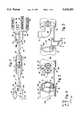
- FIG. 1is a perspective view of the apparatus for in site saphenous vein bypass of the present invention, shown in one intended environment;
- FIG. 2is a perspective detail view of the operating ends of the control catheter and operating catheter, with the valvulotome and electrode in their housed positions, showing the cap in an exploded relationship with the control catheter;
- FIG. 3is a perspective detail view of the operating ends of the control catheter and operating catheter, with the valvulotome and electrode in their operating positions;
- FIG. 4is a cross-sectional view of the valvulotome as seen along the line 4--4 in FIG. 3;
- FIG. 5is a cross-sectional view of the electrode as seen along the line 5--5 in FIG. 1;
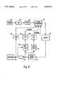
- FIG. 6is a block diagram of the electrical components associated with the electrode
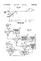
- FIG. 7is a flow chart of the microprocessor logic for generating the control signal for the electrode
- FIG. 8is a graph of the preferred temperature profile versus time for blood vein electro-coagulation
- FIG. 9is a flow chart of the microprocessor logic for establishing the temperature profile shown in FIG. 8;
- FIG. 10is a cross-sectional view of an alternate embodiment of the electrode for in situ saphenous vein bypass applications, as would be seen along the line 5--5 in FIG. 1, with portions broken away for clarity;
- FIG. 11a cross-sectional view of yet another alternate embodiment of the electrode for varicose vein treatment applications, as would be seen along the line 5--5 in FIG. 1, with portions broken away for clarity and with a delivery catheter shown in phantom; and
- FIG. 12is a perspective view of an alternate embodiment of the valvulotome of the present invention, with the blades in the open position.
- an apparatusfor in situ modification of a saphenous vein 12 for arterial use.
- the apparatus 10is used to modify the saphenous vein 12 by disrupting one-way valves 14 in the saphenous vein 12 and by electro-ligating side branches 16 to the saphenous vein 12.
- the valves 14, until they are disruptedpermit only venous blood flow through the saphenous vein 12 and not arterial blood flow, i.e., undisrupted valves 14 permit blood flow through the saphenous vein 12 only toward the mink of the patient's body, in the direction indicated by the arrow 18, and prevent blood flow in the opposite direction.
- the apparatus 10includes an operating catheter 20 and a control catheter 22.
- a first end 20a of the operating catheter 20is connected to a flat working hub 24 having opposed first and second flat surfaces 24a, 24b, while a first end 22a of the control catheter 22 is connected to a flat cutting hub 26 having opposed first and second flat surfaces 26a, 26b.
- both cathetershave a 1:1 torque ratio; consequently, turning a hub 24, 26 a predetermined number of degrees (e.g., flipping the hub 24 180 degrees to reverse the position of the first side 24a and second side 24b) will cause the associated catheter 20, 22 to rotate the same number of degrees along its entire length.
- a stainless steel guide wire 28extends through both the catheters 20, 22 and the hubs 24, 26.
- the guide wire 28has a diameter of approximately forty five hundredths of a millimeter (0.45 mm).
- Each hub 24, 26includes a respective locking screw 30, 32 that can be manually tightened against the guide wire 28 to hold the guide wire 28 stationary relative to the hubs 24, 26 and catheters 20, 22.
- FIG. 1further shows that the working hub 24 is connected to a video monitor 34, e.g., a Sony video monitor, by an appropriate sterilizable camera coupler (not shown) of a type well known in the art.
- a video monitor 34e.g., a Sony video monitor
- an appropriate sterilizable camera coupler(not shown) of a type well known in the art.
- the optical system including the camera coupler and video monitorincludes a camera of the type well-known in the art having an auto-iris feature.
- the camera couplercan be housed within the working hub 24.
- the working hub 24is connected to a light source 36, preferably a three hundred watt (300 w) Xenon light source of the type well-known in the art. Additionally, the working hub 24 is operably connected to a source 38 of electrical power by means more fully disclosed below.
- the source 38 of electrical poweris an electro-cautery power source suitable for supplying electricity for cauterizing tissue, such as the Bovie brand generator made by Valley Labs of Colorado.
- a source 40 of irrigating fluidis connected to the working hub 24 for purposes to be shortly disclosed.
- FIG. 1also shows that the cutting hub 26 is connected to a drain line 42.
- control catheter 22preferably is a biocompatible, flexible plastic tube, more preferably made of polyvinylchloride (PVC), and the catheter 22 defines a longitudinal axis 22b and an open second end 22c.
- a cap 43can be positioned over the open second end 22c of the control catheter 22 for purposes to be disclosed below.
- the control catheter 22is formed by extrusion with a cylindrical drain lumen 44 and a cylindrical valvulotome lumen 46, both of which extend the length of the control catheter 22 into the cutting hub 26.
- the drain lumen 44is in fluid communication with the drain line 42 shown in FIG. 1.
- the diameter "D1" of the drain lumen 44is preferably about one and eight tenths millimeters (1.8 mm), and the diameter "D2" of the valvulotome lumen 46 is preferably about two-tenths of a millimeter (0.2 mm).
- the outside diameter "OD1" of the control catheter 22is between about two and one tenth millimeter (2.1 mm) and two and seven tenths millimeters (2.7 mm).
- FIGS. 2 and 3show that the guide wire 28 extends through the valvulotome lumen 46, and, when the locking screw 32 is not tightened against it, the guide wire 28 is slidably disposed in the control catheter 22. On the other hand, when the locking screw 32 is tightened, the guide wire 28 is held stationary in the control catheter 22.
- a third lumen(not shown) can be formed in the control catheter 22 for holding the guide wire 28 in lieu of the valvulotome lumen 46.
- a stainless steel or rigid hard plastic valvulotome 48is reciprocally disposed in the valvulotome lumen 46.
- the valvulotome 48includes a cutting blade 50 that is formed with an interior cutting edge 52.
- the cutting edge 52 of the valvulotome 48is oriented toward the control catheter 22.
- the cutting edge 52is sharpened by electro-discharge machining, and in brief reference to FIG. 4, the cutting blade 50 defines an angle ⁇ of about twenty (20) degrees, with the cutting edge 52 establishing the apex of the angle ⁇ .
- the valvulotome 48is shaped as a partial cylinder. Also, the control catheter 22 is formed with a cut-out or recess 49 which is configured complementarily with the valvulotome 48. Consequently, when in a housed position shown in FIG. 2, the valvulotome 48 fits closely within the recess 49, i.e., the valvulotome 48 is flush with the control catheter 22 when the valvulotome 48 is in the housed position.
- FIGS. 2 and 3further show that the valvulotome 48 also includes a valvulotome shaft 54.
- the valvulotome shaft 54extends through the valvulotome lumen 46 of the control catheter 22, for manipulation of the valvulotome 48 by a surgeon. More particularly, the valvulotome 48 can be manipulated between the housed position shown in FIG. 2, wherein the valvulotome 48 presents an atraumatic aspect (i.e., is flush with the wall of the control catheter 22 as described above), and a cutting position shown in FIG. 3, wherein the valvulotome 48 can be manipulated to cut valves 14.
- the valvulotome shaftpreferably has a torque ratio of 1:1.
- the cutting edge 52 of the valvulotome 48faces a circumferentially-oriented wall 49a of the control catheter 22, to shield the cutting edge 52 from the saphenous vein 12.
- the only part of the valvulotome 48 which is exposed to the saphenous vein 12is a non-sharp, preferably curvilinear outer edge 53.
- the cutting edge 52is distanced from the second end 22c of the control catheter 22, and the cutting blade 50 is mined radially outwardly away from the drain lumen 44. Thereby, the cutting edge 52 is exposed to the saphenous vein 12.
- the valvulotome shaft 54can be pulled relative to the control catheter 22 (i.e., moved to the left in FIG. 3) to move the cutting edge 52 against and into the valves 14 to thereby disrupt valves 14 in the saphenous vein 12.
- FIGS. 2 and 3show that the operating catheter 20 defines a longitudinal axis 20b which is generally coincidental with the axis 22b of the control catheter 22. Also, the operating catheter 20 is formed with a second end 20c, and the second end 20c of the operating catheter 20 is preferably closely spaced from the second end 22c of the control catheter 22. In the presently preferred embodiment, the second end 20c of the operating catheter 20 is spaced is distance "s" of about one centimeter (1 cm) from the second end 22c of the control catheter 22.
- the operating catheter 20preferably is a biocompatible, flexible plastic tube, more preferably made of polyvinylchloride (PVC). It can be appreciated in reference to FIGS. 2 and 3 that the operating catheter 20 is formed by extrusion with a cylindrical guide wire lumen 56, a cylindrical electrode lumen 58, and a cylindrical fiber lumen 60, all of which extend the length of the operating catheter 20 into the working hub 24. Also, a lumen is formed which closely holds a cylindrical illumination fiber 62.
- PVCpolyvinylchloride
- each lumen 56, 58, 60is in fluid communication with the source 40 of irrigating fluid (FIG. 1).
- the illumination fiber 62is connected to the light source 36.
- the diameter "D3" of the illumination fiber 62is preferably about six tenths of a millimeter (0.6 mm), and the diameter "D4" of the electrode lumen 58 is preferably about one and one-tenth of a millimeter (1.1 mm).
- the diameter of the guide wire lumen 56is approximately equal to the diameter of the illumination fiber 62, and the diameter of the fiber lumen 60 is about equal to the diameter of the electrode lumen 58.
- the outside diameter "OD2" of the operating catheter 20is between about two and one tenth millimeter (2.1 mm) and two and seven tenths millimeters (2.7 mm).
- FIGS. 2 and 3show that the guide wire 28 extends through the guide wire lumen 56 of the operating catheter 20 into the working hub 24 (FIG. 1), and, when the locking screw 30 is not tightened against it, the guide wire 28 is slidably disposed in the operating catheter 20. On the other hand, when the locking screw 30 is tightened, the guide wire 28 is held stationary in the operating catheter 20.
- a light transmitting memberpreferably an optical image fiber 64, is removably disposed in the fiber lumen 60.
- the image fiber 64includes a distal lens and the fiber 64 is connected to the camera coupling discussed previously, which in turn is connected to the video monitor 34.
- the image fiber 64can be removed from the fiber lumen 60, the operating catheter 20 disposed of, and the image fiber 64 reused in another like operating catheter (not shown).
- the image fiber 64is held in the fiber lumen 60 by at least one threaded fastener 66 (FIG. 1) which is threadably engaged with the working hub 24 and which can be tightened against the fiber 64 to hold the fiber 64 stationary within the operating catheter 20.
- an electrode 68is reciprocally disposed in the electrode lumen 58 and extends through the working hub 24, where it terminates in a standard banana plug connector for connection with the source 38 of electricity (FIG. 1).
- the electrode 68can be moved between a housed position, shown in FIG. 2, wherein the electrode 68 is disposed substantially within the operating catheter 20, and an operating position, shown in FIG. 3, in which the electrode 68 extends beyond the second end 20c of the operating catheter 20 for exposing the electrode 68 to tissue.
- each flat hub 24, 26can be marked or scored with indicators, e.g. , lines 67, 69 shown in FIG. 1, to indicate the position of the electrode 68 or valvulotome 48, respectively.
- FIG. 5shows the details of the electrode 68.
- the electrode 68includes an elongated electrical conductor 70 having a cylindrically-shaped electrode tip 72 formed integrally on the distal end of the conductor 70.
- the conductor 70has an electrical resistance below ten ohms per foot (10 ⁇ /ft).
- the conductor 70 with electrode tip 72is made of type 304 stainless steel.
- FIG. 5also shows that the conductor 70 has an outside diameter D C1 of about between about sixteen thousandths of an inch and eighteen thousandths of an inch (0.016"-0.018"). Also, the conductor 70 tapers radially inwardly to a bendable segment 74 having a diameter D C2 of about five thousandths of an inch (0.005"). As the skilled artisan will appreciate, the bendable segment 74 is malleable and flexible. Consequently, the segment 74 can be bent into a predetermined curvilinear shape to facilitate advancing the electrode 68 into a side branch 16 for electro cautery thereof.
- the electrode tip 72is formed with a rounded distal end 76.
- An abutment surface 78is established by the electrode tip 72, and the abutment surface 78 radially projects beyond the conductor 70.
- the electrode tip 72has a diameter D 3 of between about twenty eight thousandths of an inch and ninety two thousandths of an inch (0.028"-0.092"), and more preferably the diameter D 3 is about seven-tenths of a millimeter (0.7 mm), i.e., about twenty eight thousandths of an inch (0.028").
- the length L of the electrode tip 72is between about one to ten millimeters (1-10 mm). Specifically, the length L is established to be approximately equal to the maximum expected diameter of the side branch into which the electrode 68 is advanced.
- a non-sticking, non-insulative substance 80is deposited on the surface of the electrode tip 72 to inhibit sticking of the electrode tip 72 to body tissue during energization of the electrode tip 72.
- the substance 80is chrome which is deposited on the electrode tip 72 by vapor deposition.
- the electrode tip 72can be coated with titanium nitride.
- FIG. 5also shows that an insulative sheath 82 surrounds the conductor 70 and abuts the abutment surface 78 of the electrode tip 72.
- the outer surface of the sheath 82is flush with the outer surface of the electrode tip 72, and an air space 83 is established between the sheath 82 and the bendable segment 74.
- the sheath 82is bonded to the conductor 70 with a high-temperature epoxy.
- the sheath 82is made of an electrically resistive, smooth, biocompatible material, such as PEBAX® made by Atochem, Inc. of New Jersey, or TFE Teflon®, which typically has a dielectric strength of about seven hundred to one thousand volts per mil of material (700-1000 v/mil). Also, the sheath 82 is made of a material which will not easily melt or breakdown under the high temperatures that are typically generated during electro cautery. Further, the sheath 82 should be made of a material that has a low coefficient of friction.
- PEBAX®made by Atochem, Inc. of New Jersey
- TFE Teflon®typically has a dielectric strength of about seven hundred to one thousand volts per mil of material (700-1000 v/mil).
- the sheath 82is made of a material which will not easily melt or breakdown under the high temperatures that are typically generated during electro cautery. Further, the sheath 82 should be made of a material that has a low coefficient of friction.
- PEBAX®is the presently preferred material of choice for the sheath 82 in light of its above-mentioned attributes and because it is relatively flexible, elastic, and has a low coefficient of friction. These attributes permit the sheath 82 to be easily advanced through a potentially curvilinear, small-diameter lumen of blood vein or an endoscopic instrument.
- the outside diameter OD 4 of the sheath 82(and, hence, the outside diameter of the electrode 68) is preferably equal to less than about one millimeter (1 mm). In one presently preferred embodiment, the outside diameter OD 4 of the sheath 82 is between about twenty eight thousandths of an inch and ninety two thousandths of an inch (0.028"-0.092").
- Alternative materials which can be used for the sheath 82include polyimide, polyethylene, and polypropylene.
- a sensor 84(FIG. 3) can be attached to the electrode tip 72.
- the sensor 84can be a thermocouple, thermistor, or other suitable temperature-sensing device.
- the sensor 84can be a pressure sensor for sensing fluid pressure at the distal end of the electrode 68.
- FIG. 5shows that a flat, generally parallellepiped-shaped bend indicator 86 is bonded to the sheath 82 outside the operating catheter 20 shown in FIGS. 2 and 3, i.e., proximal to the first end 20a of the operating catheter 20.
- the indicator 86is formed with a projecting edge 87 that is distanced from the sheath 82.
- the bend indicator 86is oriented during manufacturing such that the projecting edge 87 extends outwardly in the same direction as the bend of the bendable segment 74 of the conductor 70.
- the indicator 87remains outside the patient's body during surgery, and the operator of the electrode 68 can consequently ascertain during surgery the direction in which the bendable segment 74 of the conductor 70 has been bent.
- FIG. 5shows that the bend indicator 86 is formed integrally with a metal jacket 88, and the jacket 88 surrounds the sheath 82 to transmit torque to the electrode 68.
- An insert 89 made of silicone rubberis disposed between the jacket 88 and sheath 82.
- the electrode 68has a proximal end 90, and a high voltage line, including a high voltage lead 91 and high voltage insulator 92, abuts the proximal end 90 of the electrode 68.
- a wire 93is soldered to the high voltage lead 91 and conductor 70 to further ensure electrical contact between the two components. It is to be appreciated that the high voltage lead 91 in turn is electrically connected to the source 38 of electricity (FIG. 1).
- the electrode 68is electrically connected to the source 38 of electricity. It is to be appreciated that both the sensor 84 and electrode tip 72 of the electrode 68 are electrically connected to the source 38 of electricity.
- the electrode 68is selectively energized by the source 38 of electricity to stop blood flow from side branches and other tissue within the saphenous vein.
- the source 38 of electricityis electrically connected to a microprocessor 94 which is advantageously a type "486" microprocessor.
- a microprocessor 94which is advantageously a type "486" microprocessor.
- an equivalent programmed chipcan be used in lieu of the microprocessor 94.
- the microprocessor 94is electrically connected to the source 38, and the microprocessor 94 generates a control signal for controlling the source 38 in response to, inter alia, signals from the sensor 84.
- indicators 95FIG. 1 can be provided for displaying electrode 68 voltage, current, impedance, temperature, and other parameters, in accordance with the operation of the electrode 68 disclosed below.
- the sensor 84is connected to an analog-to-digital (“A/D") converter 96, for converting the analog temperature signal from the sensor 84 into a digitized signal.
- A/D converter 96can advantageously be a type AD57804P converter made by Burr Brown, or some other suitable converter known in the art.
- FIG. 6further shows that the A/D converter 96 is connected to a noise filter 97.
- the noise filter 97can be a hardware or, more preferably, software filter which filters noise from the digitized signal from the sensor 84.
- the filter 97can be programmed to discriminate against five hundred kilohertz (500 KHz), sixty Hertz (60 Hz) or fifty Hertz (50 Hz) noise from nearby electrical components.
- the filter 97can also be programmed to average a predetermined number (e.g., ten) of consecutive signals from the sensor 84 and output a signal representative of the average, or the filter 97 can be a low-pass filter.
- the noise filter 97is a software filter, it can function by averaging a plurality of (e.g., ten) sensor signals in accordance with means well-known in the art.
- the filter 97can be programmed to block a signal from the sensor 84 which greatly varies from the immediately previous signal. A great variance from one signal to the next may indicate an erroneous or spurious signal level. In other words, if a first signal from the sensor indicates an electrode tip 72 temperature of, e.g., eighty degrees centigrade (80° C.), and a second signal that is immediately temporally after the first indicates an electrode tip 72 temperature which varies by more than a predetermined mount (e.g., 10° C.) from the first signal, the filter 97 blocks the second signal from further processing.
- the hardware components, if any, of both the A/D converter 96 and the noise filter 97can be housed in the electrode 68 or source 38.
- the filter 97is a software filter
- the software filter 97can be part of the microprocessor 94.
- FIG. 6also shows that a timer 98 is provided which monitors the length of time the source 38 energizes the electrode tip 72.
- the timer 98generates a signal representative of the length of time of electrode tip 72 energization and sends this signal to the microprocessor 94.
- the microprocessor 94causes the source 38 to stop energizing the electrode tip 72.
- componentsare provided for measuring the output voltage and current of the source 38 of electricity, and for providing signals representative of the output voltage, current, power, and impedance (and, hence, the voltage, current, power, and tissue impedance at the tip of the electrode tip 72) to the microprocessor 94.
- a component 99e.g., a current sensing transformer or resistor, is connected in series between the source 38 of electricity and the electrode tip 72, and a current rectifier filter (“R/F”) 100 samples the voltage upstream and downstream of the component 99. Accordingly, the current R/F 100 outputs a signal representative of the output current of the source 38 of electricity.
- a voltage sampling R/F 101is provided for generating a signal representative of the output voltage of the source 38 of electricity.
- both the current and voltage R/Fs 100, 101can be full wave diode rectifiers with associated filtering capacitors connected in a configuration well-known in the art.
- FIG. 6shows that the current and voltage R/Fs 100, 101 are respectively connected to A/D converters 96a, 96b, each of which is substantially similar to the temperature A/D converter 96.
- both A/D converters 96a, 96bare connected to the microprocessor 94.
- the microprocessor 94generates an output control signal and sends the control signal to an electrical buffer 102.
- the buffer 102is any suitable device which essentially isolates the microprocessor 94 from the source 38 of electricity, and which provides correct driving signals to the source 38.
- the output signal from the buffer 102is sent to the source 38 of electricity to control the output power of the source 38 of electricity.
- the control signalcan be used to vary the output voltage of the source 38 of electricity, or the modulation of the signal from the source 38 of electricity, by means well-known in the art.
- the signal from the buffer 102can be used as the bias signal to a power transistor (not shown) that is part of the output circuitry of the source 38 of electricity. Consequently, as the signal from the buffer 102 changes, the bias of the transistor changes to change the output of the source 38 of electricity.
- the microprocessor 94commences a sampling cycle at begin circle 103. From the circle 103, the microprocessor proceeds to block 103a, wherein a software counter "T” is set equal to zero. Then at block 104, "T" is set equal to T+1. If, at block 104, T equals a predetermined software counter "T 1 ", the microprocessor 94 stops, i.e., exits the routine shown in FIG. 7.
- the microprocessor 94proceeds in parallel to decision blocks 106, 108, and 110, and to blocks 112 and 114.
- decision blocks 106, 108, 110the microprocessor 94 retrieves from memory and then respectively compares source 38 of electricity output voltage (V b ), electrode tip 72 temperature (T b ), and source 38 of electricity output current (I b ) to respective predetermined voltage, temperature, and current setpoints V1, T1, I1.
- the setpoints V1, T1, I1may be variably patient-dependent, power-dependent, or temperature-dependent, in that the respective values of the setpoints may be established depending upon the characteristics of the patient as indicated by the output parameters of the source 38 of electricity, or by the power setting of the source 38, or by the temperature indicated by the sensor 84. If either V b or Tb exceeds its predetermined setpoint, or if I b falls below its predetermined setpoint, the microprocessor 94 generates a control signal to cause the source 38 of electricity to stop energizing the electrode tip 72. Otherwise, the microprocessor 94 proceeds to blocks 116, 118.
- the microprocessor 94calculates the impedance (Z b ) of the tissue adjacent the electrode tip 72 by dividing V b by I b . Then, the microprocessor 94 moves to decision block 120, where the microprocessor 94 compares Z b to a predetermined setpoint impedance Z1. If Z b exceeds Z1, poor electrical connection or poor placement of the electrode tip 72 may be indicated. In such a case, the microprocessor 94 generates a control signal to cause the source 38 of electricity to stop energizing the electrode tip 72. As intended by the present invention, the source 38 of electricity is deenergized before Z b reaches zero (0). Else, the microprocessor 94 proceeds to blocks 122 and 124. In the presently preferred embodiment, Z1 is set equal to about fifty ohms.
- phase difference between V b and I bcan be measured for determining the capacitive impedance component and resistive impedance component, and then either impedance component can be used in lieu of or in addition to Z b .
- the phase difference between V b and I bcan be used as an input to the microprocessor 94 in lieu of or in addition to the parameters discussed above.
- the microprocessor 94calculates the output power (P b ) of the source 38 of electricity by multiplying V b and I b . Then, the microprocessor 94 moves to decision block 126, where the microprocessor 94 compares P b to a predetermined setpoint power P1. If P b exceeds P1, the microprocessor 94 generates a control signal to cause the source 38 of electricity to stop energizing the electrode tip 72. Otherwise, the microprocessor 94 proceeds to return block 127, and thence back to block 104.
- the microprocessor 94respectively calculates the difference between V b , I b , and V b-1 , I b-1 to yield ⁇ V, ⁇ I, where V b-1 , I b-1 , are the respective voltage and current values calculated in the immediately preceding cycle.
- the microprocessor 94moves to respective decision blocks 130, 132.
- the microprocessor 94compares ⁇ V to a predetermined voltage difference, i.e., ⁇ V 2 . If ⁇ V exceeds ⁇ V 2 , the microprocessor 94 moves to block 134, wherein the microprocessor 94 generates a control signal to cause the source 38 of electricity to deactivate or to reduce its power output by a predetermined increment ⁇ P, e.g., by two to four watts (2 w-4 w). Otherwise, the microprocessor 94 moves to block 127 and thence back to block 104 for another cycle.
- ⁇ Pe.g., by two to four watts
- the microprocessor 94compares ⁇ I to a predetermined current difference, i.e., ⁇ I 2 . If ⁇ I exceeds ⁇ I 2 , the microprocessor 94 moves to block 134, wherein the microprocessor 94 generates a control signal to cause the source 38 of electricity to reduce its power output by ⁇ P. Otherwise, the microprocessor 94 moves to block 127 and thence to block 104 for another cycle.
- the microprocessor 94compares Z b to a predetermined constant impedance setpoint Z1. As shown in FIG. 7 starting at block 122, the microprocessor 94 also compares Z b to a variable impedance setpoint Z2 which is patient-dependent.
- the microprocessor 94moves to block 135, wherein the microprocessor 94 retrieves a predetermined impedance limit Z2 by accessing a data table and using Z3 as the entering argument.
- a representative tableis provided herein as Table 1.
- the microprocessor 94moves to decision block 136, wherein Z b is compared to Z2. If Z b exceeds Z2, the microprocessor 94 moves to block 134 to reduce source 38 of electricity output power or deenergize the electrode tip 72 altogether, and thence to block 128 to generate a tone representative of Z b . Otherwise, the microprocessor 94 moves directly to block 128 to generate a tone representative of Z b . It is to be understood that while block 128 in FIG. 7 indicates that a tone representative of impedance is generated, the tone or other tones could be generated which are representative of the other parameters discussed herein. From block 128, the microprocessor 94 moves to block 127 and then returns to block 104.
- the operation of the microprocessor 94 at block 122ensures that the entering argument variable Z3 is set equal to a relatively stabilized Z b . More particularly, for a brief initial stabilization period (T2), power interruption is avoided when minor transients in impedance (Z b ) might occur and otherwise cause the microprocessor 94 to deenergize the source 38 of electricity. Stated differently, the microprocessor 94 reduces source 38 output power during the stabilization time T2 only in the instance when Z b is less than the initial default value of Z2, which is accordingly set equal to a relatively low (e.g., eight hundred ohms (800 ⁇ ) value.
- a relatively lowe.g., eight hundred ohms (800 ⁇
- Z bcan be expected to reach a steady state value while the tissue surrounding the electrode 68 is treated by the electrode 36.
- the microprocessor 94proceeds to decision block 138, wherein the microprocessor 94 compares ⁇ Z to a predetermined impedance difference, i.e., ⁇ Z4. If ⁇ Z exceeds ⁇ Z4, the microprocessor 94 moves to block 134, wherein the microprocessor 94 generates a control signal to cause the source 38 of electricity to reduce its power output by ⁇ P, and thence to block 127. Otherwise, the microprocessor 94 moves directly to block 127, and thence to block 104 for another cycle.
- ⁇ Za predetermined impedance difference
- the microprocessor 94determines whether the time rate of change of V b , I b , or Z b are excessive, and, if so, the microprocessor 94 reduces the output power of the source 38 of electricity, or deenergizes the electrode tip 72 altogether.
- the present inventionalso envisions calculating the time rate of change of temperature T b in a like manner and reducing the output power of the source 38 of electricity in response to an excessively rapid increase in T b or in the time rate of change of T b , as more fully disclosed below in reference to FIG. 9.
- the present inventioncontemplates the above-disclosed operation of the microprocessor 94 because, as recognized by the present invention, the tissue impedance at the tip of the electrode tip 72, and the temperature of the tip of the electrode tip 72, is affected by the characteristics of the tissue immediately adjacent the electrode tip 72.
- the impedance at the electrode tip 72 tipis relatively low. In contrast, when the tissue has just undergone cauterization, the impedance at the electrode tip 72 tip is relatively high.
- the output voltage, current, and impedance of the source 38 of electricityare all affected by the cauterization of tissue adjacent the electrode tip 72.
- the magnitudes of the output voltage and current of the source 38 of electricity, and the magnitude of the impedance of the tissue adjacent the electrode tip 72are dependent upon the body characteristics of the patient.
- the temperature (T b ) of the electrode tip 72 tipalso depends in part upon the characteristics of the tissue adjacent the tip of the electrode tip 72.
- the present inventionensures that tissue adjacent the venous wall is not damaged any further than necessary to effect cauterization. Also, by precisely controlling the output of the source 38 of electricity, the present invention ensures that tissue is precisely cauterized as appropriate for side branch 16 closure.
- the present inventionenables the surgeon to precisely control the source 38.
- V1, I1, Z1, Z2, Z3, P1, T1, and ⁇ Z4can all vary with the power setting of the source 38 of electricity.
- a data table correlating power setting with predetermined setpointsis stored in the electronic memory of the microprocessor 94 for look-up by the microprocessor 94 at the appropriate decision blocks discussed above.
- the disclosure aboverefers to an embodiment wherein the power output of the source 38 of electricity is established in response to, among other things, tissue impedance.
- the present inventionalso contemplates other means for establishing the power output of the source 38.
- the power output of the source 38 of electricitycan be keyed to time, or to tissue temperature as measured by the sensor 84.
- the source 38can initially output "P" watts for a predetermined time period, e.g., one second, and then step decreased to 0.75 P watts. After another predetermined time period, e.g., two seconds, the power output can be step decreased to 0.5 P watts and held at 0.5 P watts for yet another predetermined time period, e.g., seventeen seconds. Then, the source 38 can be deenergized after a total energization time of twenty seconds. The total energization time may be as low as six seconds, however.
- the source 38can initially output "P" watts until a predetermined tissue temperature, e.g., one hundred twenty degrees Fahrenheit (120° F.), has been reached, and then step decreased to 0.75 P watts. After another predetermined temperature, e.g., one hundred fifty degrees Fahrenheit (150° F.), has been reached, the power output can be step decreased to 0.5 P watts and held at 0.5 P watts until yet another predetermined temperature, e.g., one hundred eighty degrees Fahrenheit (180° F.), has been reached, at which point the source 38 is deenergized.
- a predetermined tissue temperaturee.g., one hundred twenty degrees Fahrenheit (120° F.
- the power outputcan be step decreased to 0.5 P watts and held at 0.5 P watts until yet another predetermined temperature, e.g., one hundred eighty degrees Fahrenheit (180° F.), has been reached, at which point the source 38 is deenergized.
- energization of the source 38 of electricitycan be decreased or stopped immediately in response to any one or more of the previously discussed parameters (temperature, impedance, voltage, current, phase, and time rates of change thereof) reaching a respective predetermined safety shut-off setpoint.
- the initial power output "P"can be decreased by a predetermined amount, e.g., one watt, and then the cycle recommended.
- the safety shut-off setpoint for a particular parameter, e.g., impedanceis reached, but the value of the parameter unexpectedly 38 of electricity can nonetheless be decreased or stopped.
- FIGS. 1-3In the overall operation of the apparatus 10, reference is made to FIGS. 1-3. A first small incision is made in the saphenous vein 12 in the lower leg of the patient, near the ankle or calf. Also, a second small incision is made in the saphenous vein 12 in the upper leg or groin of the patient.
- the cap 43is positioned over the second end 22c of the control catheter 22, and the capped second end 22c is then advanced into the first incision, through the saphenous vein 12, and out of the second incision. Then, the cap 43 is removed and the guide wire 28 is advanced through the guide wire lumen 46 of the control catheter 22 from the first end 22a through the second end 22c, and into and through the guide wire lumen 56 of the operating catheter 20.
- the catheters 20, 22are positioned on the guide wire as appropriate to establish the distance "s" between the second ends 20c, 22c of the catheters 20, 22, and the locking screws 30, 32 on the hubs 24, 26 are then tightened to prevent further relative motion between the catheters 20, 22. It will be appreciated that with this combination of structure, the image fiber 64 transmits an image of objects located between the second ends 20c, 22c of the catheters 20, 22 for display on the video monitor 34.
- both cathetersare advanced into the saphenous vein 12 with the electrode 68 and valvulotome 48 in the housed positions shown in FIG. 2.
- the cathetersare so advanced until the second end 20c of the operating catheter 20 is positioned on a proximal side of a valve 14 and the second end 22c of the control catheter 22 is positioned on the distal side of the valve 14.
- the valvulotome 48is then advanced through the valve 14 to the cutting position shown in FIG. 3. It will be appreciated that when the valvulotome 48 is advanced through the valve 14 to the proximal side thereof, the optical fiber 64 transmits an image of the valvulotome 48 and the valve 14 about to be disrupted. To disrupt the valve 14, the valvulotome 48 is pulled back distally into the valve 14. After valve disruption, the valvulotome 48 is moved to the housed configuration shown in FIG. 2 to present an atraumatic aspect, and the catheters 20, 22 are advanced together through the saphenous vein 12 to sequentially disrupt the valves 14.
- the electrode tip 72 of the electrode 68is selectively advanced out of the electrode lumen 58 to the operating position shown in FIG. 3, and into the side branch 16 sought to be ligated or against the tissue sought to be cauterized.
- the source 38 of electricityactivated to electro-ligate the side branch.
- the electrode 68is then retracted into the operating catheter 20. In the preferred embodiment the electrode 68 is manually moved to the operating position by, e.g., urging against the bend indicator 86.
- irrigating fluid from the source 40 of fluidis flushed through the lumens 56, 58, 60. Excess irrigating fluid is then drained by gravity through the drain lumen 44 of the control catheter 22, thereby alleviating potentially deleterious fluid build-up in the patient's leg.
- the electrode 68 disclosed aboveis a monopolar device, it may also be a bi-polar device, e.g., the electrode 68 can have electrodes configured like those disclosed in co-pending U.S. patent application Ser. No. 08/054,123, filed Apr. 26, 1993, for an invention entitled “Bi-Polar Electrocauterizer", now abandoned, assigned to the sole owner of the present invention and incorporated herein by reference.
- valves within the saphenous veinmay be disrupted with other valvulotomes (not shown) prior to using the present invention.
- the control catheter 22can be omitted, and the operating catheter 24 advanced over the guide wire 28 proximally to distally through the saphenous vein to ligate side branches as disclosed.
- the control catheter 22can be included for drainage purposes, with the valvulotome 48 omitted.
- FIG. 8shows a desired time-dependent temperature profile for electrocautery of tissue within a blood vessel
- FIG. 9shows the steps implemented by the microprocessor 94 for establishing the desired time-dependent temperature profile.
- the desired temperature profileis characterized by four intervals.
- the first intervalcommences at an initial time t 0 and an electrode temperature of 98.6° F. and ends at a first time t 1 , e.g., two seconds.
- the first time t 1corresponds approximately to an electrode temperature of 120° F.
- the second intervalcommences at the first time t 1 and ends at a second time t 1 , e.g., four seconds, corresponding to an electrode temperature of approximately 150° F.
- the length of the second intervalin the exemplary embodiment shown, is two seconds.
- the third intervalcommences at the second time t 2 and ends at a third time t 3 , e.g., ten seconds.
- the length of the third intervalin the exemplary embodiment shown, is six seconds.
- the fourth intervalcommences at the third time t 3 and ends at a fourth time t 4 .
- the microprocessor 94controls the energization of the source 38 of electricity to maintain the time rate of change of electrode temperature in the first interval to be equal to or greater than a first lower slope limit "B" and to be less than or equal to a first upper slope limit "A".
- the first lower slope limit "B"is equal to about fifteen degrees Fahrenheit per second (15° F./sec) and the first upper slope limit "A" is equal to about twenty degrees Fahrenheit per second (20° F./sec).
- the microprocessor 94controls the energization of the source 38 of electricity to maintain the time rate of change of electrode temperature in the second interval to be equal to or greater than a second lower slope limit "D" and to be less than or equal to a second upper slope limit "C".
- the second lower slope limit "D"is equal to about ten degrees Fahrenheit per second (10° F./sec) and the second upper slope limit "C” is equal to about twenty degrees Fahrenheit per second (20° F./sec).
- the values of the second lower slope limit "D" and the second upper slope limit “C”can vary with the characteristics of the particular patient being treated.
- the values of the second lower slope limit “D” and the second upper slope limit “C”can be multiplied by a factor which is linearly related to the actual time rate of change of temperature during the first interval.
- This factorcan be, e.g., the ratio of the difference between the average of the upper and lower limits "A", "B” and the lower limit "B” and the difference between the actual time rate of change of temperature in the first interval (dT 1 /dt) and the first lower slope limit "B".
- factoris(0.5(A+B)-B)/(dT 1 /dt-B).
- the values of the second lower slope limit "D" and the second upper slope limit “C”can be determined by entering a table with the actual time rate of change of temperature in the first interval (dT 1 /dt) as the entering argument. Still further, for each electrode type and size, a corresponding look-up table (or factor “f") can be provided. And, corresponding look-up tables (or factors "f") can be established for side branch applications and varicose vein application.
- FIG. 8shows that the microprocessor 94 controls the energization of the source 38 of electricity to maintain the time rate of change of electrode temperature in the third interval to be about equal to a constant predetermined slope, e.g., three degrees Fahrenheit per second (3° F./sec). Like the slope in the second interval, the slope in the third interval can be modified, if desired; based upon the previous actual temperature profile.
- the fourth intervalis defined by an endpoint at the fourth time t 4 which in turn is established as disclosed below.
- the microprocessor 94moves to decision block 152, wherein the microprocessor 94 determines whether the current interval is the first interval. If so, the microprocessor 94 moves to block 154 to adjust the power setting of the source 38 of electricity as appropriate to maintain the actual time rate of change of electrode temperature (dT/dt) between the first lower and upper slope limits "B" and "A".
- the microprocessor 94moves to decision block 156, wherein the microprocessor 94 determines whether the current interval is the second interval. If so, the microprocessor 94 moves to block 158 to establish the second upper and lower slope limits "C", "D" as described based upon the actual time rate of change of electrode temperature (dT/dt) (and, hence, based upon the patient's characteristics) in the first interval. Next, the microprocessor 94 moves to block 160 to adjust the power setting of the source 38 of electricity as appropriate to maintain the actual time rate of change of electrode temperature (dT/dt) in the second interval between the second lower and upper slope limits "D" and "C".
- the microprocessor 94moves to decision block 162, wherein the microprocessor 94 determines whether the current interval is the third interval. If so, the microprocessor 94 moves to block 164 to adjust the power setting of the source 38 of electricity as appropriate to maintain the actual time rate of change of electrode temperature (dT/dt) in the third interval at a constant predetermined slope. From block 164, or from decision block 162 if the test there was negative, the microprocessor 94 moves to block 166 to maintain the power setting of the source 38 of electricity at the setting that was established as of the third time t 3 .
- the microprocessor 94determines the endpoint of the fourth interval. In other words, at decision block 168 the microprocessor 94 determines when the fourth time t 4 has been reached.
- the microprocessor 94determines that the endpoint of the fourth interval has been reached when any one of three conditions occurs. First, the microprocessor 94 determines that the endpoint of the fourth interval has been reached when electrode temperature equals or exceeds a predetermined end temperature T end , e.g., 180° F. Also, the microprocessor 94 determines that the endpoint of the fourth interval has been reached when the change of temperature ⁇ T from the third time t 3 and the time of the current test equals or exceeds a predetermined end temperature delta ⁇ T end , e.g., 15° F.
- a predetermined end temperature T ende.g. 180° F.
- the microprocessor 94determines that the endpoint of the fourth interval has been reached when the change of temperature ⁇ T from the third time t 3 and the time of the current test equals or exceeds a predetermined end temperature delta ⁇ T end , e.g., 15° F.
- the microprocessor 94determines that the endpoint of the fourth interval has been reached when the differential temperature DT equals or exceeds a predetermined differential temperature dT end , e.g., 8° F. in the past second. It is to be appreciated in light of the above discussion that in determining the differential temperature DT, the microprocessor 94 considers the change in electrode temperature in the immediately preceding second of time. In the event that the microprocessor 94 determines, at decision block 168, that the endpoint of the fourth interval has been reached, the microprocessor 94 ends at end state 170. Otherwise, the microprocessor 94 loops back to block 166 each, e.g., fiftieth of a second.
- an alternate embodiment of the electrode of the present invention for electro-ligation of saphenous vein side branchesis shown, generally designated 172.
- the electrode 172includes a hollow cylindrically-shaped electrode tip 174 which is made of type 304 stainless steel.
- FIG. 10also shows that the tip 174 has an outside diameter D D1 of about twenty eight thousandths of an inch (0.028").
- the electrode tip 174is formed with a rounded distal end 176.
- a medial cylindrical segment 177 having an outside diameter D D2 that is slightly smaller than the outside diameter D D1 of the tip 174is formed integrally with the tip 174, and a ring-shaped abutment surface 178 is consequently established between the tip 174 and the medial segment 177.
- a cylindrical proximal segment 179 having an outside diameter D D3 that is slightly smaller than the outside diameter D D2 of the medial segment 177is formed integrally with the medial segment 177, and a proximal ring-shaped abutment surface 180 is consequently established between the medial segment 177 and the proximal segment 179.
- both abutment surfaces 178, 180are orthogonal to the long axis 182 of the electrode 172. Furthermore, the length LL of the electrode tip 174 from the distal end 176 to the medial abutment surface 178 is about three hundred fifteen thousandths of an inch (0.315").
- a cylindrical channel-like cavity 184is established by the hollow tip 174, medial segment 177, and proximal segment 179.
- a temperature sensorpreferably a thermocouple 186, is disposed in the cavity 184. It can be appreciated in reference to FIG. 10 that the cavity 184 is enclosed by the wall of the tip 174, medial segment 177, and proximal segment 179.
- the thermocouple 186is established by soldering together the distal ends of first and second electrically conductive wires 188, 190.
- FIG. 10shows that the wires 188, 190 extend through the electrode 172.
- an electrical signalis developed by the thermocouple 186 and transmitted through the wires 188, 190 to the electrical components disclosed above. This signal is representative of the temperature of the electrode 200. Consequently, the microprocessor 94 can receive a signal from the thermocouple 186 that is representative of the temperature of the electrode 172 and, hence, that is representative of the temperature of tissue in contact with the electrode 172.
- an epoxy material 192fills the portion of the cavity 184 of the tip 174 that is not occupied by the thermocouple 186 and wires 188, 190.
- a flexible spring 194is soldered to the proximal segment 179 and abuts the proximal abutment surface 180.
- the spring 194is preferably closed-wound as shown, but it can be open wound.
- the spring 194establishes a flexible electrically conductive joining member which mechanically and electrically couples the electrode 172 with a distal projection 195 of a rigid stainless steel tube 196.
- the spring 194is soldered to the distal projection 195.
- the tube 196 with distal projection 195is electrically connected to a source of electricity, such as the source 38 with feedback control device disclosed above, for energizing the electrode 172 through the tube 196 and spring 194.
- an insulative sheath 198surrounds the tube 196, spring 194, and medial segment 177, and the sheath 198 abuts the medial abutment surface 180.
- the outer surface of the sheath 198is flush with the outer surface of the electrode tip 174, and the sheath 198 is bonded to the medial segment 177 with a high-temperature epoxy.
- the sheath 198 shown in FIG. 10is made of an electrically resistive, smooth, biocompatible material, such as PEBAX®.
- FIG. 11shows an electrode, generally designated 200, that can be used for such an application by advancing a delivery catheter 202 in which the electrode 200 is disposed into a varicose vein of a patient's leg through a small percutaneous incision, and then activating the electrode 200 to electrically ligate the vein.
- the delivery catheter 202is the endoscope disclosed in U.S. Pat. No. 5,318,526 for an invention entitled "Flexible Endoscope with Hypotube Activating Wire", owned by the assignee of the present invention and incorporated herein by reference.
- the electrode 200includes a hollow cylindrically-shaped electrode tip 204 which is made of type 304 stainless steel.
- FIG. 11also shows that the tip 204 has an outside diameter D E1 of about twenty eight thousandths of an inch (0.028").
- the electrode tip 204is formed with a rounded distal end 206.
- a medial cylindrical segment 207 having an outside diameter D E2 of about eighteen thousandths of an inch (0.018")is formed integrally with the tip 204, and a ring-shaped abutment surface 208 is consequently established between the tip 204 and the medial segment 207.
- the abutment surface 208is orthogonal to the long axis 209 of the electrode 200.
- the length LL 1 of the electrode tip 204 from the distal end 206 to the abutment surface 208is about three hundred fifteen thousandths of an inch (0.315").
- FIG. 11shows that the medial segment 207 tapers proximally radially inwardly to a hollow tubular joining member 210 having an outside diameter D E3 of about fourteen thousandths of an inch (0.014").
- the joining member 210tapers proximally radially outwardly to a hollow electrode tube 212 having an outside diameter D E4 of about sixteen thousandths of an inch (0.016").
- the joining member 210, tube 212, and medial segment 207are formed integrally together and are made of stainless steel.
- the tube 212is electrically connected to a source of electricity, such as the source 38 with feedback control device disclosed above, for energizing the electrode 200.
- a cylindrical channel-like cavity 214is established by the hollow tip 204, medial segment 207, joining member 210, and tube 212.
- a temperature sensorpreferably a thermocouple 216, is disposed in the cavity 214. It can be appreciated in reference to FIG. 11 that the cavity 214 is enclosed by the wall of the tip 204, medial segment 207, joining member 210, and tube 212.
- the thermocouple 216is established by soldering together the distal ends of first and second electrically conductive wires 218, 220.
- FIG. 11shows that the wires 218, 220 extend through the electrode 200.
- an electrical signalis developed by the thermocouple 216 and transmitted through the wires 218, 220 to the electrical components disclosed above. This signal is representative of the temperature of the electrode 200. Consequently, the microprocessor 94 can receive a signal from the thermocouple 216 that is representative of the temperature of the electrode 200 and, hence, that is representative of the temperature of tissue in contact with the electrode 200.
- an epoxy material 222fills the portion of the cavity 214 of the tip 204 that is not occupied by the thermocouple 216 and wires 218, 220.
- an insulative sheath 224surrounds the structure discussed above, and the sheath 224 abuts the abutment surface 208.
- the outer surface of the sheath 224is flush with the outer surface of the electrode tip 204, and the sheath 224 is bonded to the medial segment 207 with a high-temperature epoxy.
- the sheath 224 shown in FIG. 11is made of an electrically resistive, smooth, biocompatible material, such as PEBAX®.
- the valvulotome 226includes a fixed blade 228 and a movable blade 230. More particularly, the valvulotome 226 can be disposed in a lumen 232 of a catheter 234 that can inserted into an endoscope or other catheter, e.g., the operating catheter 20 or control catheter 22 shown in FIG. 3.
- a shaft 228A of the fixed blade 228is bonded or otherwise fixedly attached to the catheter 234, and a shaft 230A of the movable blade 230 is reciprocally disposed in the lumen 232 and is closely supported thereby.
- FIG. 12shows that the fixed blade 228 defines a fixed sharpened cutting edge 236, while the movable blade 230 defines a sharpened movable cutting edge 238 facing the fixed blade 228.
- the movable cutting edge 238is reciprocally movable in the directions indicated by the indicator 240 between a closed position, wherein the blades 228, 230 are closely juxtaposed, and the open position shown in FIG. 12, wherein the blades 228, 230 are spaced apart for receiving tissue therebetween.
- FIG. 12shows that the fixed blade 228 defines a fixed sharpened cutting edge 236, while the movable blade 230 defines a sharpened movable cutting edge 238 facing the fixed blade 228.
- the fixed cutting edge 236is slightly offset, by a distance ⁇ , from the centerline 242 of the shaft 228A of the fixed blade 228. Both cutting edges 236, 238 can be sharpened by, e.g., grinding techniques known in the art.
- FIG. 12moreover shows that an activating wire 244 is reciprocally disposed in the catheter 234.
- the activating wire 244is fixedly attached by means well-known in the art to the shaft 230A of the movable blade 230.
- the wire 244extends through an operating handle 246 and is attached to a manipulable handle 248. Consequently, the wire 244 and, hence, movable cutting blade 230 can be moved relative to the fixed blade 228 by appropriately manipulating the manipulable handle 248.
- a biasing spring 250can be engaged in accordance with principles well-known in the art to the wire 244 and operating handle 246 to urge the wire 244 proximally or distally, as appropriate, and thereby bias the movable blade 230 to the closed or open position, as desired.
Landscapes
- Health & Medical Sciences (AREA)
- Surgery (AREA)
- Engineering & Computer Science (AREA)
- Life Sciences & Earth Sciences (AREA)
- Biomedical Technology (AREA)
- Molecular Biology (AREA)
- Nuclear Medicine, Radiotherapy & Molecular Imaging (AREA)
- Plasma & Fusion (AREA)
- Physics & Mathematics (AREA)
- Heart & Thoracic Surgery (AREA)
- Medical Informatics (AREA)
- Otolaryngology (AREA)
- Animal Behavior & Ethology (AREA)
- General Health & Medical Sciences (AREA)
- Public Health (AREA)
- Veterinary Medicine (AREA)
- Cardiology (AREA)
- Surgical Instruments (AREA)
Abstract
Description
TABLE 1______________________________________ Z3(Ohms) Z2(Ohms)______________________________________ 0-49 0 50-74 200 75-99 225 100-124 300 125-149 350 150-174 400 175-199 425 200-224 500 225-249 550 250-274 575 275-299 600 300-324 625 325-349 650 350-374 675 375-449 700 450-474 725 475-499 750 500-524 775 525-549 800 550-574 825 575-599 850 600-799 900 800-999 999______________________________________
Claims (17)
Priority Applications (2)
| Application Number | Priority Date | Filing Date | Title |
|---|---|---|---|
| US08/484,187US5658282A (en) | 1994-01-18 | 1995-06-07 | Apparatus for in situ saphenous vein bypass and less-invasive varicose vein treatment |
| US08/789,266US6267758B1 (en) | 1994-01-18 | 1997-01-28 | Apparatus for in situ saphenous vein bypass and less-invasive varicose vein treatment |
Applications Claiming Priority (3)
| Application Number | Priority Date | Filing Date | Title |
|---|---|---|---|
| US08/183,994US5437664A (en) | 1994-01-18 | 1994-01-18 | Apparatus and method for venous ligation |
| US31507494A | 1994-09-29 | 1994-09-29 | |
| US08/484,187US5658282A (en) | 1994-01-18 | 1995-06-07 | Apparatus for in situ saphenous vein bypass and less-invasive varicose vein treatment |
Related Parent Applications (2)
| Application Number | Title | Priority Date | Filing Date |
|---|---|---|---|
| US08/183,994Continuation-In-PartUS5437664A (en) | 1994-01-18 | 1994-01-18 | Apparatus and method for venous ligation |
| US31507494AContinuation-In-Part | 1994-01-18 | 1994-09-29 |
Related Child Applications (1)
| Application Number | Title | Priority Date | Filing Date |
|---|---|---|---|
| US08/789,266ContinuationUS6267758B1 (en) | 1994-01-18 | 1997-01-28 | Apparatus for in situ saphenous vein bypass and less-invasive varicose vein treatment |
Publications (1)
| Publication Number | Publication Date |
|---|---|
| US5658282Atrue US5658282A (en) | 1997-08-19 |
Family
ID=27391769
Family Applications (2)
| Application Number | Title | Priority Date | Filing Date |
|---|---|---|---|
| US08/484,187Expired - LifetimeUS5658282A (en) | 1994-01-18 | 1995-06-07 | Apparatus for in situ saphenous vein bypass and less-invasive varicose vein treatment |
| US08/789,266Expired - LifetimeUS6267758B1 (en) | 1994-01-18 | 1997-01-28 | Apparatus for in situ saphenous vein bypass and less-invasive varicose vein treatment |
Family Applications After (1)
| Application Number | Title | Priority Date | Filing Date |
|---|---|---|---|
| US08/789,266Expired - LifetimeUS6267758B1 (en) | 1994-01-18 | 1997-01-28 | Apparatus for in situ saphenous vein bypass and less-invasive varicose vein treatment |
Country Status (1)
| Country | Link |
|---|---|
| US (2) | US5658282A (en) |
Cited By (99)
| Publication number | Priority date | Publication date | Assignee | Title |
|---|---|---|---|---|
| US5836945A (en)* | 1997-02-20 | 1998-11-17 | Perkins; Rodney C. | Biological vessel harvesting device |
| US5925043A (en)* | 1997-04-30 | 1999-07-20 | Medquest Products, Inc. | Electrosurgical electrode with a conductive, non-stick coating |
| US5954715A (en)* | 1997-06-05 | 1999-09-21 | Adiana, Inc. | Method and apparatus for tubal occlusion |
| US5984937A (en)* | 1997-03-31 | 1999-11-16 | Origin Medsystems, Inc. | Orbital dissection cannula and method |
| US5989208A (en)* | 1997-05-16 | 1999-11-23 | Nita; Henry | Therapeutic ultrasound system |
| EP0983751A1 (en)* | 1998-08-30 | 2000-03-08 | Moshe Ein-Gal | Electrocoagulation apparatus for varicose veins |
| US6090118A (en) | 1998-07-23 | 2000-07-18 | Mcguckin, Jr.; James F. | Rotational thrombectomy apparatus and method with standing wave |
| US6231524B1 (en)* | 1996-09-03 | 2001-05-15 | Clinical Innovation Associates, Inc. | Pressure catheter device with enhanced fluid monitoring features |
| US6270831B2 (en) | 1998-04-30 | 2001-08-07 | Medquest Products, Inc. | Method and apparatus for providing a conductive, amorphous non-stick coating |
| US6475214B1 (en) | 2000-05-01 | 2002-11-05 | Biosense Webster, Inc. | Catheter with enhanced ablation electrode |
| US6475644B1 (en) | 1998-11-18 | 2002-11-05 | Radiovascular Systems, L.L.C. | Radioactive coating solutions methods, and substrates |
| US20030208214A1 (en)* | 2000-03-20 | 2003-11-06 | Amir Loshakove | Anastomotic connector and graft expander for mounting a graft |
| US20030225426A1 (en)* | 2002-04-03 | 2003-12-04 | Thomas J. Fogarty, M.D. | Methods and systems for vein harvesting and fistula creation |
| US6671561B1 (en) | 2000-05-01 | 2003-12-30 | Biosense Webster, Inc. | Catheter with electrode having hydrogel layer |
| US20040024393A1 (en)* | 2002-08-02 | 2004-02-05 | Henry Nita | Therapeutic ultrasound system |
| US6712810B2 (en) | 1999-02-01 | 2004-03-30 | Adiana, Inc. | Method and apparatus for tubal occlusion |
| US20040073247A1 (en)* | 1998-05-29 | 2004-04-15 | By-Pass, Inc. | Method and apparatus for forming apertures in blood vessels |
| US6726704B1 (en) | 1998-05-29 | 2004-04-27 | By-Pass, Inc. | Advanced closure device |
| US20040087985A1 (en)* | 1999-03-19 | 2004-05-06 | Amir Loshakove | Graft and connector delivery |
| US20040204725A1 (en)* | 2001-06-26 | 2004-10-14 | Bayer Hanspeter Robert | Conduit harvesting instrument and method |
| US20050033281A1 (en)* | 2002-05-23 | 2005-02-10 | Adiana, Inc. | Catheter placement detection system and operator interface |
| US20050064616A1 (en)* | 2003-09-23 | 2005-03-24 | Been-Yih Jin | Semiconductor channel on insulator structure |
| US20050096670A1 (en)* | 2003-10-31 | 2005-05-05 | Parris Wellman | Surgical end effector |
| US20050096645A1 (en)* | 2003-10-31 | 2005-05-05 | Parris Wellman | Multitool surgical device |
| US20050096646A1 (en)* | 2003-10-31 | 2005-05-05 | Parris Wellman | Surgical system for retracting and severing tissue |
| US20050096671A1 (en)* | 2003-10-31 | 2005-05-05 | Parris Wellman | Control mechanism for a surgical instrument |
| US20050096677A1 (en)* | 2003-10-31 | 2005-05-05 | Parris Wellman | Space-creating retractor with vessel manipulator |
| US20050101983A1 (en)* | 1998-05-29 | 2005-05-12 | By-Pass,Inc. | Method and apparatus for forming apertures in blood vessels |
| US20050192606A1 (en)* | 2004-02-27 | 2005-09-01 | Paul Ram H.Jr. | Valvulotome with a cutting edge |
| US20050216303A1 (en)* | 2000-04-11 | 2005-09-29 | Sony Corporation | Communication system, communication method, distribution apparatus, distribution method and terminal apparatus |
| US6953355B1 (en)* | 1999-06-01 | 2005-10-11 | Lizell Christopher A | Modular support system |
| US6979338B1 (en) | 1998-05-29 | 2005-12-27 | By-Pass Inc. | Low profile anastomosis connector |
| US20060030849A1 (en)* | 2004-08-05 | 2006-02-09 | Vnus Medical Technologies, Inc. | Methods and apparatus for coagulating and/or constricting hollow anatomical structures |
| US7022131B1 (en) | 1998-05-29 | 2006-04-04 | By-Pass Inc. | Methods and devices for vascular surgery |
| US7033354B2 (en) | 2002-12-10 | 2006-04-25 | Sherwood Services Ag | Electrosurgical electrode having a non-conductive porous ceramic coating |
| US7037316B2 (en) | 1997-07-24 | 2006-05-02 | Mcguckin Jr James F | Rotational thrombectomy device |
| US20060122613A1 (en)* | 2004-12-02 | 2006-06-08 | Kirsch John M | Fixator for a fractured bone |
| US7063711B1 (en) | 1998-05-29 | 2006-06-20 | By-Pass, Inc. | Vascular surgery |
| US20060173474A1 (en)* | 2003-10-31 | 2006-08-03 | Parris Wellman | Surgical device having a track to guide an actuator |
| US20060189979A1 (en)* | 2005-02-23 | 2006-08-24 | Esch Brady D | Methods and apparatus for coagulating and/or constricting hollow anatomical structures |
| US20060189967A1 (en)* | 2005-02-21 | 2006-08-24 | Leonardo Masotti | Device, a catheter, and a method for the curative treatment of varicose veins |
| US7125406B2 (en) | 2002-09-13 | 2006-10-24 | Given Kenna S | Electrocautery instrument |
| US20070260172A1 (en)* | 1999-02-16 | 2007-11-08 | Henry Nita | Pre-shaped therapeutic catheter |
| US20090018563A1 (en)* | 2007-07-13 | 2009-01-15 | E-Globe Technologies Ltd. | Stripping device for removal of varicose veins |
| US20090036840A1 (en)* | 2006-11-22 | 2009-02-05 | Cytyc Corporation | Atraumatic ball tip and side wall opening |
| US20090125023A1 (en)* | 2007-11-13 | 2009-05-14 | Cytyc Corporation | Electrosurgical Instrument |
| US7645261B2 (en) | 1999-10-22 | 2010-01-12 | Rex Medical, L.P | Double balloon thrombectomy catheter |
| US20100286719A1 (en)* | 2004-02-27 | 2010-11-11 | Paul Ram H | Valvulotome device and method |
| US7867163B2 (en) | 1998-06-22 | 2011-01-11 | Maquet Cardiovascular Llc | Instrument and method for remotely manipulating a tissue structure |
| US7938842B1 (en) | 1998-08-12 | 2011-05-10 | Maquet Cardiovascular Llc | Tissue dissector apparatus |
| US7955293B2 (en) | 2002-08-26 | 2011-06-07 | Flowcardia, Inc. | Ultrasound catheter for disrupting blood vessel obstructions |
| US7972265B1 (en) | 1998-06-22 | 2011-07-05 | Maquet Cardiovascular, Llc | Device and method for remote vessel ligation |
| US20110166519A1 (en)* | 2010-01-04 | 2011-07-07 | Tyco Healthcare Group, L.P. | Apparatus and methods for treating hollow anatomical structures |
| US20110172688A1 (en)* | 2010-01-11 | 2011-07-14 | Tyco Healthcare Group Lp | Conduit Harvesting Instrument and Method |
| US7981133B2 (en) | 1995-07-13 | 2011-07-19 | Maquet Cardiovascular, Llc | Tissue dissection method |
| US8043251B2 (en) | 2003-01-14 | 2011-10-25 | Flowcardia, Inc. | Ultrasound catheter and methods for making and using same |
| US8062566B2 (en) | 2003-04-08 | 2011-11-22 | Flowcardia, Inc. | Method of manufacturing an ultrasound transmission member for use in an ultrasound catheter device |
| US8133236B2 (en) | 2006-11-07 | 2012-03-13 | Flowcardia, Inc. | Ultrasound catheter having protective feature against breakage |
| US8221343B2 (en) | 2005-01-20 | 2012-07-17 | Flowcardia, Inc. | Vibrational catheter devices and methods for making same |
| US8226566B2 (en) | 2009-06-12 | 2012-07-24 | Flowcardia, Inc. | Device and method for vascular re-entry |
| US8231619B2 (en) | 2010-01-22 | 2012-07-31 | Cytyc Corporation | Sterilization device and method |
| US8241210B2 (en) | 1998-06-22 | 2012-08-14 | Maquet Cardiovascular Llc | Vessel retractor |
| US8246643B2 (en) | 2006-11-07 | 2012-08-21 | Flowcardia, Inc. | Ultrasound catheter having improved distal end |
| US20120289947A1 (en)* | 2010-01-18 | 2012-11-15 | Wolfgang Neuberger | Device and method for removing veins |
| US8414543B2 (en) | 1999-10-22 | 2013-04-09 | Rex Medical, L.P. | Rotational thrombectomy wire with blocking device |
| US8550086B2 (en) | 2010-05-04 | 2013-10-08 | Hologic, Inc. | Radiopaque implant |
| US8568404B2 (en) | 2010-02-19 | 2013-10-29 | Covidien Lp | Bipolar electrode probe for ablation monitoring |
| US8613751B2 (en) | 2003-11-24 | 2013-12-24 | Flowcardia, Inc. | Steerable ultrasound catheter |
| US8617096B2 (en) | 2004-08-26 | 2013-12-31 | Flowcardia, Inc. | Ultrasound catheter devices and methods |
| US8641630B2 (en) | 2003-09-19 | 2014-02-04 | Flowcardia, Inc. | Connector for securing ultrasound catheter to transducer |
| US8647293B2 (en) | 2002-08-02 | 2014-02-11 | Flowcardia, Inc. | Therapeutic ultrasound system |
| US8702727B1 (en) | 1999-02-01 | 2014-04-22 | Hologic, Inc. | Delivery catheter with implant ejection mechanism |
| US8882759B2 (en) | 2009-12-18 | 2014-11-11 | Covidien Lp | Microwave ablation system with dielectric temperature probe |
| US20140364883A1 (en)* | 2012-03-20 | 2014-12-11 | Cardiovascular Systems, Inc. | Controller for an atherectomy device |
| US8961423B2 (en) | 2003-02-26 | 2015-02-24 | Flowcardia, Inc. | Ultrasound catheter apparatus |
| US20160038722A1 (en)* | 2014-08-06 | 2016-02-11 | Cook Medical Technologies Llc | Cutting edge cutting catheter |
| US9282984B2 (en) | 2006-04-05 | 2016-03-15 | Flowcardia, Inc. | Therapeutic ultrasound system |
| US20170245922A1 (en)* | 2016-02-29 | 2017-08-31 | Terumo Kabushiki Kaisha | Dissecting device and dissecting system |
| US9782191B2 (en) | 2014-01-21 | 2017-10-10 | Cook Medical Technologies Llc | Cutting devices and methods |
| CN108472007A (en)* | 2015-11-02 | 2018-08-31 | 皇家飞利浦有限公司 | The active distributed of high-voltage power supply for ultrasonic transducer |
| US10064611B2 (en) | 2015-07-22 | 2018-09-04 | Covidien Lp | Methods and devices for vein harvesting |
| US10299770B2 (en) | 2006-06-01 | 2019-05-28 | Maquet Cardiovascular Llc | Endoscopic vessel harvesting system components |
| CN109843160A (en)* | 2016-07-29 | 2019-06-04 | 阿克松疗法公司 | Devices, systems, and methods for treating heart failure through cardiac nerve ablation |
| US10357263B2 (en) | 2012-01-18 | 2019-07-23 | C. R. Bard, Inc. | Vascular re-entry device |
| US10507012B2 (en) | 2000-11-17 | 2019-12-17 | Maquet Cardiovascular Llc | Vein harvesting system and method |
| US10575835B2 (en) | 2014-10-14 | 2020-03-03 | Covidien Lp | Methods and devices for vein harvesting |
| US10582983B2 (en) | 2017-02-06 | 2020-03-10 | C. R. Bard, Inc. | Ultrasonic endovascular catheter with a controllable sheath |
| US10646210B2 (en) | 2014-10-14 | 2020-05-12 | Covidien Lp | Methods and devices for vein harvesting |
| US10758256B2 (en) | 2016-12-22 | 2020-09-01 | C. R. Bard, Inc. | Ultrasonic endovascular catheter |
| US10835267B2 (en) | 2002-08-02 | 2020-11-17 | Flowcardia, Inc. | Ultrasound catheter having protective feature against breakage |
| US10912610B2 (en) | 2015-02-05 | 2021-02-09 | Axon Therapies, Inc. | Devices and methods for treatment of heart failure by splanchnic nerve ablation |
| US11344750B2 (en) | 2012-08-02 | 2022-05-31 | Flowcardia, Inc. | Ultrasound catheter system |
| US11413090B2 (en) | 2020-01-17 | 2022-08-16 | Axon Therapies, Inc. | Methods and devices for endovascular ablation of a splanchnic nerve |
| US11547466B2 (en) | 2018-06-20 | 2023-01-10 | Covidien Lp | Visualization devices and methods for use in surgical procedures |
| US11596726B2 (en) | 2016-12-17 | 2023-03-07 | C.R. Bard, Inc. | Ultrasound devices for removing clots from catheters and related methods |
| US11633206B2 (en) | 2016-11-23 | 2023-04-25 | C.R. Bard, Inc. | Catheter with retractable sheath and methods thereof |
| US11712296B2 (en) | 2017-12-17 | 2023-08-01 | Axon Therapies, Inc. | Methods and devices for endovascular ablation of a splanchnic nerve |
| US11751939B2 (en) | 2018-01-26 | 2023-09-12 | Axon Therapies, Inc. | Methods and devices for endovascular ablation of a splanchnic nerve |
| US11806073B2 (en) | 2019-06-20 | 2023-11-07 | Axon Therapies, Inc. | Methods and devices for endovascular ablation of a splanchnic nerve |
Families Citing this family (67)
| Publication number | Priority date | Publication date | Assignee | Title |
|---|---|---|---|---|
| US7452358B2 (en) | 1996-01-05 | 2008-11-18 | Thermage, Inc. | RF electrode assembly for handpiece |
| US7473251B2 (en) | 1996-01-05 | 2009-01-06 | Thermage, Inc. | Methods for creating tissue effect utilizing electromagnetic energy and a reverse thermal gradient |
| US7115123B2 (en) | 1996-01-05 | 2006-10-03 | Thermage, Inc. | Handpiece with electrode and non-volatile memory |
| US7022121B2 (en) | 1999-03-09 | 2006-04-04 | Thermage, Inc. | Handpiece for treatment of tissue |
| US7141049B2 (en) | 1999-03-09 | 2006-11-28 | Thermage, Inc. | Handpiece for treatment of tissue |
| US7229436B2 (en) | 1996-01-05 | 2007-06-12 | Thermage, Inc. | Method and kit for treatment of tissue |
| US7006874B2 (en) | 1996-01-05 | 2006-02-28 | Thermage, Inc. | Treatment apparatus with electromagnetic energy delivery device and non-volatile memory |
| US7189230B2 (en) | 1996-01-05 | 2007-03-13 | Thermage, Inc. | Method for treating skin and underlying tissue |
| US7267675B2 (en) | 1996-01-05 | 2007-09-11 | Thermage, Inc. | RF device with thermo-electric cooler |
| US7364577B2 (en) | 2002-02-11 | 2008-04-29 | Sherwood Services Ag | Vessel sealing system |
| WO2003053266A2 (en)* | 1999-06-30 | 2003-07-03 | Thermage, Inc. | Liquid cooled rf handpiece |
| ES2262639T3 (en) | 2001-04-06 | 2006-12-01 | Sherwood Services Ag | SHUTTER AND DIVIDER OF GLASSES WITH BUMPER MEMBERS N OCONDUCTIVES. |
| US9510900B2 (en)* | 2003-01-21 | 2016-12-06 | Baylis Medical Company Inc. | Electrosurgical device for creating a channel through a region of tissue and methods of use thereof |
| US7223266B2 (en) | 2003-02-04 | 2007-05-29 | Cardiodex Ltd. | Methods and apparatus for hemostasis following arterial catheterization |
| US6964661B2 (en)* | 2003-04-02 | 2005-11-15 | Boston Scientific Scimed, Inc. | Endovenous ablation mechanism with feedback control |
| US20050215994A1 (en)* | 2003-08-21 | 2005-09-29 | Stephen Solomon | Tunneling device |
| US7367976B2 (en) | 2003-11-17 | 2008-05-06 | Sherwood Services Ag | Bipolar forceps having monopolar extension |
| EP1814478A4 (en)* | 2004-11-22 | 2011-05-18 | Cardiodex Ltd | Techniques for heat-treating varicose veins |
| JP2006180936A (en)* | 2004-12-24 | 2006-07-13 | Olympus Medical Systems Corp | Fever treatment device |
| KR100640283B1 (en)* | 2004-12-28 | 2006-11-01 | 최정숙 | High frequency electrosurgical electrode |
| US12161390B2 (en) | 2006-09-29 | 2024-12-10 | Boston Scientific Medical Device Limited | Connector system for electrosurgical device |
| US11666377B2 (en) | 2006-09-29 | 2023-06-06 | Boston Scientific Medical Device Limited | Electrosurgical device |
| US7766907B2 (en)* | 2006-12-28 | 2010-08-03 | St. Jude Medical, Atrial Fibrillation Division, Inc. | Ablation catheter with sensor array and discrimination circuit to minimize variation in power density |
| EP2182875A4 (en) | 2007-08-15 | 2011-08-24 | Cardiodex Ltd | Systems and methods for puncture closure |
| US20090234344A1 (en)* | 2008-03-11 | 2009-09-17 | Timothy Lavender | Method for the transcutaneous treatment of varicose veins and spider veins using dual laser therapy |
| US8303582B2 (en)* | 2008-09-15 | 2012-11-06 | Tyco Healthcare Group Lp | Electrosurgical instrument having a coated electrode utilizing an atomic layer deposition technique |
| US8142473B2 (en) | 2008-10-03 | 2012-03-27 | Tyco Healthcare Group Lp | Method of transferring rotational motion in an articulating surgical instrument |
| US8114122B2 (en) | 2009-01-13 | 2012-02-14 | Tyco Healthcare Group Lp | Apparatus, system, and method for performing an electrosurgical procedure |
| US8187273B2 (en) | 2009-05-07 | 2012-05-29 | Tyco Healthcare Group Lp | Apparatus, system, and method for performing an electrosurgical procedure |
| US8246618B2 (en) | 2009-07-08 | 2012-08-21 | Tyco Healthcare Group Lp | Electrosurgical jaws with offset knife |
| US8133254B2 (en) | 2009-09-18 | 2012-03-13 | Tyco Healthcare Group Lp | In vivo attachable and detachable end effector assembly and laparoscopic surgical instrument and methods therefor |
| US8112871B2 (en) | 2009-09-28 | 2012-02-14 | Tyco Healthcare Group Lp | Method for manufacturing electrosurgical seal plates |
| US9113940B2 (en) | 2011-01-14 | 2015-08-25 | Covidien Lp | Trigger lockout and kickback mechanism for surgical instruments |
| USD680220S1 (en) | 2012-01-12 | 2013-04-16 | Coviden IP | Slider handle for laparoscopic device |
| EP4599879A2 (en) | 2012-05-31 | 2025-08-13 | Boston Scientific Medical Device Limited | Radiofrequency perforation apparatus |
| US11937873B2 (en) | 2013-03-12 | 2024-03-26 | Boston Scientific Medical Device Limited | Electrosurgical device having a lumen |
| EP2968846B1 (en) | 2013-03-12 | 2022-05-04 | Baylis Medical Company Inc. | Medical device having a support structure |
| CA3220441A1 (en) | 2013-03-15 | 2015-09-17 | Boston Scientific Medical Device Limited | Electrosurgical device having a distal aperture |
| CN105682726B (en) | 2013-08-07 | 2020-01-03 | 贝利斯医疗公司 | Method and apparatus for puncturing tissue |
| US10661057B2 (en) | 2013-12-20 | 2020-05-26 | Baylis Medical Company Inc. | Steerable medical device handle |
| AU2016319002B2 (en) | 2015-09-09 | 2021-05-13 | Boston Scientific Medical Device Limited | Epicardial access system & methods |
| WO2017118948A1 (en) | 2016-01-07 | 2017-07-13 | Baylis Medical Company Inc. | Hybrid transseptal dilator and methods of using the same |
| CN110114027B (en) | 2016-11-01 | 2022-09-06 | 贝利斯医疗公司 | Method and apparatus for puncturing tissue |
| BR112020011128A2 (en) | 2017-08-10 | 2021-05-04 | Baylis Medical Company Inc. | heat exchange device and temperature sensor and method of use |
| EP3579909B1 (en) | 2017-12-05 | 2020-09-09 | Pedersen, Wesley Robert | Transseptal guide wire puncture system |
| CN112272574A (en) | 2018-05-08 | 2021-01-26 | 贝利斯医疗公司 | Coupling mechanism for device |
| CN108670322B (en)* | 2018-06-08 | 2024-05-17 | 宁波华仁医疗科技有限公司 | Vein stripping catheter |
| KR20220021468A (en) | 2019-04-29 | 2022-02-22 | 베이리스 메디컬 컴퍼니 아이엔씨. | Transseptal system, device and method |
| US11759190B2 (en) | 2019-10-18 | 2023-09-19 | Boston Scientific Medical Device Limited | Lock for medical devices, and related systems and methods |
| US11801087B2 (en) | 2019-11-13 | 2023-10-31 | Boston Scientific Medical Device Limited | Apparatus and methods for puncturing tissue |
| US11724070B2 (en) | 2019-12-19 | 2023-08-15 | Boston Scientific Medical Device Limited | Methods for determining a position of a first medical device with respect to a second medical device, and related systems and medical devices |
| US11931098B2 (en) | 2020-02-19 | 2024-03-19 | Boston Scientific Medical Device Limited | System and method for carrying out a medical procedure |
| US12082792B2 (en) | 2020-02-25 | 2024-09-10 | Boston Scientific Medical Device Limited | Systems and methods for creating a puncture between aorta and the left atrium |
| US11986209B2 (en) | 2020-02-25 | 2024-05-21 | Boston Scientific Medical Device Limited | Methods and devices for creation of communication between aorta and left atrium |
| US11819243B2 (en) | 2020-03-19 | 2023-11-21 | Boston Scientific Medical Device Limited | Medical sheath and related systems and methods |
| US11826075B2 (en) | 2020-04-07 | 2023-11-28 | Boston Scientific Medical Device Limited | Elongated medical assembly |
| US12011279B2 (en) | 2020-04-07 | 2024-06-18 | Boston Scientific Medical Device Limited | Electro-anatomic mapping system |
| US12420067B2 (en) | 2020-05-12 | 2025-09-23 | Boston Scientific Medical Device Limited | Guidewire assembly |
| CN116437857A (en) | 2020-06-17 | 2023-07-14 | 波士顿科学医疗设备有限公司 | Electroanatomical mapping system |
| US11938285B2 (en) | 2020-06-17 | 2024-03-26 | Boston Scientific Medical Device Limited | Stop-movement device for elongated medical assembly |
| US11937796B2 (en) | 2020-06-18 | 2024-03-26 | Boston Scientific Medical Device Limited | Tissue-spreader assembly |
| US12343042B2 (en) | 2020-07-16 | 2025-07-01 | Boston Scientific Medical Device Limited | Pericardial puncture device and method |
| US12042178B2 (en) | 2020-07-21 | 2024-07-23 | Boston Scientific Medical Device Limited | System of medical devices and method for pericardial puncture |
| US12005202B2 (en) | 2020-08-07 | 2024-06-11 | Boston Scientific Medical Device Limited | Catheter having tissue-engaging device |
| US12396785B2 (en) | 2020-08-12 | 2025-08-26 | Boston Scientific Medical Device Limited | System of medical devices and method for pericardial puncture |
| CA3128527A1 (en) | 2020-09-10 | 2022-03-10 | Baylis Medical Company Inc. | Elongated medical catheter including marker band |
| US11980412B2 (en) | 2020-09-15 | 2024-05-14 | Boston Scientific Medical Device Limited | Elongated medical sheath |
Citations (26)
| Publication number | Priority date | Publication date | Assignee | Title |
|---|---|---|---|---|
| US3858586A (en)* | 1971-03-11 | 1975-01-07 | Martin Lessen | Surgical method and electrode therefor |
| US4016881A (en)* | 1973-07-04 | 1977-04-12 | Centre De Recherche Industrielle Du Quebec | Instrument for use in laparoscopic tubal cauterization |
| US4057063A (en)* | 1975-04-11 | 1977-11-08 | U.S. Philips Corporation | Device for sterilization by transuterine tube coagulation |
| US4126137A (en)* | 1977-01-21 | 1978-11-21 | Minnesota Mining And Manufacturing Company | Electrosurgical unit |
| US4311145A (en)* | 1979-07-16 | 1982-01-19 | Neomed, Inc. | Disposable electrosurgical instrument |
| US4416276A (en)* | 1981-10-26 | 1983-11-22 | Valleylab, Inc. | Adaptive, return electrode monitoring system |
| US4418692A (en)* | 1978-11-17 | 1983-12-06 | Guay Jean Louis | Device for treating living tissue with an electric current |
| US4474179A (en)* | 1981-05-20 | 1984-10-02 | F. L. Fischer Gmbh & Co. | Method and apparatus for the high frequency coagulation of protein for surgical purposes |
| US4565200A (en)* | 1980-09-24 | 1986-01-21 | Cosman Eric R | Universal lesion and recording electrode system |
| US4658819A (en)* | 1983-09-13 | 1987-04-21 | Valleylab, Inc. | Electrosurgical generator |
| US4682596A (en)* | 1984-05-22 | 1987-07-28 | Cordis Corporation | Electrosurgical catheter and method for vascular applications |
| US4907589A (en)* | 1988-04-29 | 1990-03-13 | Cosman Eric R | Automatic over-temperature control apparatus for a therapeutic heating device |
| US4966597A (en)* | 1988-11-04 | 1990-10-30 | Cosman Eric R | Thermometric cardiac tissue ablation electrode with ultra-sensitive temperature detection |
| US4998933A (en)* | 1988-06-10 | 1991-03-12 | Advanced Angioplasty Products, Inc. | Thermal angioplasty catheter and method |
| US5057105A (en)* | 1989-08-28 | 1991-10-15 | The University Of Kansas Med Center | Hot tip catheter assembly |
| US5122137A (en)* | 1990-04-27 | 1992-06-16 | Boston Scientific Corporation | Temperature controlled rf coagulation |
| US5122138A (en)* | 1990-11-28 | 1992-06-16 | Manwaring Kim H | Tissue vaporizing accessory and method for an endoscope |
| US5133725A (en)* | 1989-08-07 | 1992-07-28 | Berkshire Research And Development, Inc. | Adjustable intra-liminal valvulotome |
| US5167658A (en)* | 1991-01-31 | 1992-12-01 | Mdt Corporation | Method and apparatus for electrosurgical measurement |
| US5190541A (en)* | 1990-10-17 | 1993-03-02 | Boston Scientific Corporation | Surgical instrument and method |
| EP0558039A2 (en)* | 1992-02-28 | 1993-09-01 | Endovascular, Inc. | Electro-ligator and valvulotomy system therefor |
| US5267994A (en)* | 1992-02-10 | 1993-12-07 | Conmed Corporation | Electrosurgical probe |
| US5304190A (en)* | 1992-05-08 | 1994-04-19 | Ethicon, Inc. | Endoscopic cutting apparatus |
| US5370645A (en)* | 1993-04-19 | 1994-12-06 | Valleylab Inc. | Electrosurgical processor and method of use |
| US5498258A (en)* | 1994-09-13 | 1996-03-12 | Hakky; Said I. | Laser resectoscope with laser induced mechanical cutting means |
| US5527331A (en)* | 1993-10-13 | 1996-06-18 | Femrx | Method for prostatic tissue resection |
Family Cites Families (6)
| Publication number | Priority date | Publication date | Assignee | Title |
|---|---|---|---|---|
| US3301258A (en)* | 1963-10-03 | 1967-01-31 | Medtronic Inc | Method and apparatus for treating varicose veins |
| US5569245A (en)* | 1990-03-13 | 1996-10-29 | The Regents Of The University Of California | Detachable endovascular occlusion device activated by alternating electric current |
| US5573533A (en)* | 1992-04-10 | 1996-11-12 | Medtronic Cardiorhythm | Method and system for radiofrequency ablation of cardiac tissue |
| CA2134071C (en)* | 1992-04-23 | 1999-04-27 | Sew Wah Tay | Apparatus and method for sealing vascular punctures |
| US5437664A (en)* | 1994-01-18 | 1995-08-01 | Endovascular, Inc. | Apparatus and method for venous ligation |
| EP0740533A4 (en)* | 1994-01-18 | 1998-01-14 | Endovascular Inc | Apparatus and method for venous ligation |
- 1995
- 1995-06-07USUS08/484,187patent/US5658282A/ennot_activeExpired - Lifetime
- 1997
- 1997-01-28USUS08/789,266patent/US6267758B1/ennot_activeExpired - Lifetime
Patent Citations (26)
| Publication number | Priority date | Publication date | Assignee | Title |
|---|---|---|---|---|
| US3858586A (en)* | 1971-03-11 | 1975-01-07 | Martin Lessen | Surgical method and electrode therefor |
| US4016881A (en)* | 1973-07-04 | 1977-04-12 | Centre De Recherche Industrielle Du Quebec | Instrument for use in laparoscopic tubal cauterization |
| US4057063A (en)* | 1975-04-11 | 1977-11-08 | U.S. Philips Corporation | Device for sterilization by transuterine tube coagulation |
| US4126137A (en)* | 1977-01-21 | 1978-11-21 | Minnesota Mining And Manufacturing Company | Electrosurgical unit |
| US4418692A (en)* | 1978-11-17 | 1983-12-06 | Guay Jean Louis | Device for treating living tissue with an electric current |
| US4311145A (en)* | 1979-07-16 | 1982-01-19 | Neomed, Inc. | Disposable electrosurgical instrument |
| US4565200A (en)* | 1980-09-24 | 1986-01-21 | Cosman Eric R | Universal lesion and recording electrode system |
| US4474179A (en)* | 1981-05-20 | 1984-10-02 | F. L. Fischer Gmbh & Co. | Method and apparatus for the high frequency coagulation of protein for surgical purposes |
| US4416276A (en)* | 1981-10-26 | 1983-11-22 | Valleylab, Inc. | Adaptive, return electrode monitoring system |
| US4658819A (en)* | 1983-09-13 | 1987-04-21 | Valleylab, Inc. | Electrosurgical generator |
| US4682596A (en)* | 1984-05-22 | 1987-07-28 | Cordis Corporation | Electrosurgical catheter and method for vascular applications |
| US4907589A (en)* | 1988-04-29 | 1990-03-13 | Cosman Eric R | Automatic over-temperature control apparatus for a therapeutic heating device |
| US4998933A (en)* | 1988-06-10 | 1991-03-12 | Advanced Angioplasty Products, Inc. | Thermal angioplasty catheter and method |
| US4966597A (en)* | 1988-11-04 | 1990-10-30 | Cosman Eric R | Thermometric cardiac tissue ablation electrode with ultra-sensitive temperature detection |
| US5133725A (en)* | 1989-08-07 | 1992-07-28 | Berkshire Research And Development, Inc. | Adjustable intra-liminal valvulotome |
| US5057105A (en)* | 1989-08-28 | 1991-10-15 | The University Of Kansas Med Center | Hot tip catheter assembly |
| US5122137A (en)* | 1990-04-27 | 1992-06-16 | Boston Scientific Corporation | Temperature controlled rf coagulation |
| US5190541A (en)* | 1990-10-17 | 1993-03-02 | Boston Scientific Corporation | Surgical instrument and method |
| US5122138A (en)* | 1990-11-28 | 1992-06-16 | Manwaring Kim H | Tissue vaporizing accessory and method for an endoscope |
| US5167658A (en)* | 1991-01-31 | 1992-12-01 | Mdt Corporation | Method and apparatus for electrosurgical measurement |
| US5267994A (en)* | 1992-02-10 | 1993-12-07 | Conmed Corporation | Electrosurgical probe |
| EP0558039A2 (en)* | 1992-02-28 | 1993-09-01 | Endovascular, Inc. | Electro-ligator and valvulotomy system therefor |
| US5304190A (en)* | 1992-05-08 | 1994-04-19 | Ethicon, Inc. | Endoscopic cutting apparatus |
| US5370645A (en)* | 1993-04-19 | 1994-12-06 | Valleylab Inc. | Electrosurgical processor and method of use |
| US5527331A (en)* | 1993-10-13 | 1996-06-18 | Femrx | Method for prostatic tissue resection |
| US5498258A (en)* | 1994-09-13 | 1996-03-12 | Hakky; Said I. | Laser resectoscope with laser induced mechanical cutting means |
Non-Patent Citations (23)
| Title |
|---|
| "A Bipolar Electrode for Vascular Electrocoagulation with Alternating Current1," By Brunelle & others, Radiology, vol. 137, pp. 239-240, Oct., 1980. |
| "Ambulatory Stab Evulsion Phlebectomy for Truncal Varicose Veins," By Goren & Yellin, The American Journal of Surgery, vol. 162, pp. 166-174, Aug., 1991. |
| "Catheter for Endoluminal Bipolar Electrocoagulation1," By Becker & others, Radiology, vol. 170, pp. 561-562, Nov., 1989. |
| "Complications & Difficulties in Electrocoagulation of Varices of the Lower Extremities," By Politowsky & Others, Surgery vol. 59, No. 6, pp. 932-934, Jun. 1966. |
| "Experimental Closure of Arteriovenous Fistula by Transcatheter Electrocoagulation1," Joseph F. Phillips & others, Radiology, vol. 115, pp. 319-321, May, 1975. |
| "Home Hemodialysis," By Eschbach & Others, The Medical Letter on Drugs & Therapeutics, vol. 14, Issue 248, pp. 53-55, Jul. 12, 1968. |
| "Technical Use of Transcatheter Electrocoagulation," by Michael D. Miller & others, Work In Progress, vol. 9.129, pp. 211-214, Oct. 1978. |
| "The Mechanism Of Blood Vessel Closure By High Frequency Electrocoagulation," By Sigel & Dunn, Surgery, Gynecology & Obstetrics, pp. 823-831, Oct., 1965. |
| "Tissue Heating During Radiofrequency Catheter Ablation: AThermodynamic Model & Observations in Isolated Perfused & Superfused Canine Right Ventricular Free Wall." By Haines & Others, Pace, vol. 12, pp. 962-975, Jun. 1989. |
| "Vessel Occlusion with Transcatheter Electrocoagulation: Initial Clinical Experience1" Radiology, by William M. Thompson & others, vol. 133, pp. 335-340, Nov., 1979. |
| A Bipolar Electrode for Vascular Electrocoagulation with Alternating Current 1 , By Brunelle & others, Radiology, vol. 137, pp. 239 240, Oct., 1980.* |
| Ambulatory Stab Evulsion Phlebectomy for Truncal Varicose Veins, By Goren & Yellin, The American Journal of Surgery, vol. 162, pp. 166 174, Aug., 1991.* |
| Catheter for Endoluminal Bipolar Electrocoagulation 1 , By Becker & others, Radiology, vol. 170, pp. 561 562, Nov., 1989.* |
| Complications & Difficulties in Electrocoagulation of Varices of the Lower Extremities, By Politowsky & Others, Surgery vol. 59, No. 6, pp. 932 934, Jun. 1966.* |
| Electrothrombosis as a Treatment of Cirsoid Angioma in the Face and Scalp and Varicosis of the Leg, By Ogawa & Inoue, Plastic & Reconstructive Surgery, vol. 70, No. 3, Sep., 1982.* |
| Experimental Closure of Arteriovenous Fistula by Transcatheter Electrocoagulation 1 , Joseph F. Phillips & others, Radiology, vol. 115, pp. 319 321, May, 1975.* |
| Home Hemodialysis, By Eschbach & Others, The Medical Letter on Drugs & Therapeutics, vol. 14, Issue 248, pp. 53 55, Jul. 12, 1968.* |
| RFG 3C RF Lesion Generator System, Radionics, P.O. Box 438, 76 Cambridge Street, Burlington, Mass. 01803 0738, 1990.* |
| RFG-3C RF Lesion Generator System, Radionics, P.O. Box 438, 76 Cambridge Street, Burlington, Mass. 01803-0738, 1990. |
| Technical Use of Transcatheter Electrocoagulation, by Michael D. Miller & others, Work In Progress, vol. 9.129, pp. 211 214, Oct. 1978.* |
| The Mechanism Of Blood Vessel Closure By High Frequency Electrocoagulation, By Sigel & Dunn, Surgery, Gynecology & Obstetrics, pp. 823 831, Oct., 1965.* |
| Tissue Heating During Radiofrequency Catheter Ablation: AThermodynamic Model & Observations in Isolated Perfused & Superfused Canine Right Ventricular Free Wall. By Haines & Others, Pace, vol. 12, pp. 962 975, Jun. 1989.* |
| Vessel Occlusion with Transcatheter Electrocoagulation: Initial Clinical Experience 1 Radiology, by William M. Thompson & others, vol. 133, pp. 335 340, Nov., 1979.* |
Cited By (189)
| Publication number | Priority date | Publication date | Assignee | Title |
|---|---|---|---|---|
| US7981133B2 (en) | 1995-07-13 | 2011-07-19 | Maquet Cardiovascular, Llc | Tissue dissection method |
| US6231524B1 (en)* | 1996-09-03 | 2001-05-15 | Clinical Innovation Associates, Inc. | Pressure catheter device with enhanced fluid monitoring features |
| US5836945A (en)* | 1997-02-20 | 1998-11-17 | Perkins; Rodney C. | Biological vessel harvesting device |
| US5984937A (en)* | 1997-03-31 | 1999-11-16 | Origin Medsystems, Inc. | Orbital dissection cannula and method |
| US5925043A (en)* | 1997-04-30 | 1999-07-20 | Medquest Products, Inc. | Electrosurgical electrode with a conductive, non-stick coating |
| US5989208A (en)* | 1997-05-16 | 1999-11-23 | Nita; Henry | Therapeutic ultrasound system |
| US6068626A (en)* | 1997-06-05 | 2000-05-30 | Adiana, Inc. | Method and apparatus for tubal occlusion |
| US7905880B2 (en) | 1997-06-05 | 2011-03-15 | Cytyc Corporation | Method and apparatus for tubal occlusion |
| US6726682B2 (en) | 1997-06-05 | 2004-04-27 | Adiana, Inc. | Method and apparatus for tubal occlusion |
| US6346102B1 (en) | 1997-06-05 | 2002-02-12 | Adiana, Inc. | Method and apparatus for tubal occlusion |
| US20070215163A1 (en)* | 1997-06-05 | 2007-09-20 | Adiana, Inc. | Method and Apparatus for Tubal Occlusion |
| US7220259B2 (en) | 1997-06-05 | 2007-05-22 | Adiana, Inc. | Method and apparatus for tubal occlusion |
| US5954715A (en)* | 1997-06-05 | 1999-09-21 | Adiana, Inc. | Method and apparatus for tubal occlusion |
| US20040204720A1 (en)* | 1997-06-05 | 2004-10-14 | Adiana, Inc. | Method and apparatus for tubal occlusion |
| US7507246B2 (en) | 1997-07-24 | 2009-03-24 | Rex Medical, L.P. | Rotational thrombectomy device |
| US6602264B1 (en) | 1997-07-24 | 2003-08-05 | Rex Medical, L.P. | Rotational thrombectomy apparatus and method with standing wave |
| US7037316B2 (en) | 1997-07-24 | 2006-05-02 | Mcguckin Jr James F | Rotational thrombectomy device |
| US6270831B2 (en) | 1998-04-30 | 2001-08-07 | Medquest Products, Inc. | Method and apparatus for providing a conductive, amorphous non-stick coating |
| US7063711B1 (en) | 1998-05-29 | 2006-06-20 | By-Pass, Inc. | Vascular surgery |
| US20040073247A1 (en)* | 1998-05-29 | 2004-04-15 | By-Pass, Inc. | Method and apparatus for forming apertures in blood vessels |
| US6726704B1 (en) | 1998-05-29 | 2004-04-27 | By-Pass, Inc. | Advanced closure device |
| US6979338B1 (en) | 1998-05-29 | 2005-12-27 | By-Pass Inc. | Low profile anastomosis connector |
| US20050101983A1 (en)* | 1998-05-29 | 2005-05-12 | By-Pass,Inc. | Method and apparatus for forming apertures in blood vessels |
| US7022131B1 (en) | 1998-05-29 | 2006-04-04 | By-Pass Inc. | Methods and devices for vascular surgery |
| US8241210B2 (en) | 1998-06-22 | 2012-08-14 | Maquet Cardiovascular Llc | Vessel retractor |
| US7972265B1 (en) | 1998-06-22 | 2011-07-05 | Maquet Cardiovascular, Llc | Device and method for remote vessel ligation |
| US7867163B2 (en) | 1998-06-22 | 2011-01-11 | Maquet Cardiovascular Llc | Instrument and method for remotely manipulating a tissue structure |
| US6090118A (en) | 1998-07-23 | 2000-07-18 | Mcguckin, Jr.; James F. | Rotational thrombectomy apparatus and method with standing wave |
| US9700398B2 (en) | 1998-08-12 | 2017-07-11 | Maquet Cardiovascular Llc | Vessel harvester |
| US7938842B1 (en) | 1998-08-12 | 2011-05-10 | Maquet Cardiovascular Llc | Tissue dissector apparatus |
| US8986335B2 (en) | 1998-08-12 | 2015-03-24 | Maquet Cardiovascular Llc | Tissue dissector apparatus and method |
| US9730782B2 (en) | 1998-08-12 | 2017-08-15 | Maquet Cardiovascular Llc | Vessel harvester |
| US8460331B2 (en) | 1998-08-12 | 2013-06-11 | Maquet Cardiovascular, Llc | Tissue dissector apparatus and method |
| US6416514B1 (en) | 1998-08-30 | 2002-07-09 | Moshe Ein-Gal | Electrocoagulation apparatus |
| EP0983751A1 (en)* | 1998-08-30 | 2000-03-08 | Moshe Ein-Gal | Electrocoagulation apparatus for varicose veins |
| US6475644B1 (en) | 1998-11-18 | 2002-11-05 | Radiovascular Systems, L.L.C. | Radioactive coating solutions methods, and substrates |
| US20040255958A1 (en)* | 1999-02-01 | 2004-12-23 | Adiana, Inc. | Method and apparatus for tubal occlusion |
| US7842035B2 (en) | 1999-02-01 | 2010-11-30 | Cytyc Corporation | Method and apparatus for tubal occlusion |
| US8702727B1 (en) | 1999-02-01 | 2014-04-22 | Hologic, Inc. | Delivery catheter with implant ejection mechanism |
| US6712810B2 (en) | 1999-02-01 | 2004-03-30 | Adiana, Inc. | Method and apparatus for tubal occlusion |
| US8226645B2 (en) | 1999-02-01 | 2012-07-24 | Cytyc Corporation | Apparatus for tubal occlusion |
| US20070260172A1 (en)* | 1999-02-16 | 2007-11-08 | Henry Nita | Pre-shaped therapeutic catheter |
| US8506519B2 (en) | 1999-02-16 | 2013-08-13 | Flowcardia, Inc. | Pre-shaped therapeutic catheter |
| US20040087985A1 (en)* | 1999-03-19 | 2004-05-06 | Amir Loshakove | Graft and connector delivery |
| US20040092975A1 (en)* | 1999-03-19 | 2004-05-13 | Amir Loshakove | Anastomotic connection system |
| US6953355B1 (en)* | 1999-06-01 | 2005-10-11 | Lizell Christopher A | Modular support system |
| US7645261B2 (en) | 1999-10-22 | 2010-01-12 | Rex Medical, L.P | Double balloon thrombectomy catheter |
| US8414543B2 (en) | 1999-10-22 | 2013-04-09 | Rex Medical, L.P. | Rotational thrombectomy wire with blocking device |
| US8435218B2 (en) | 1999-10-22 | 2013-05-07 | Rex Medical, L.P. | Double balloon thrombectomy catheter |
| US9017294B2 (en) | 1999-10-22 | 2015-04-28 | Rex Medical, L.P. | Rotational thrombectomy wire with blocking device |
| US7909801B2 (en) | 1999-10-22 | 2011-03-22 | Rex Medical, L.P. | Double balloon thrombectomy catheter |
| US20030208214A1 (en)* | 2000-03-20 | 2003-11-06 | Amir Loshakove | Anastomotic connector and graft expander for mounting a graft |
| US20050216303A1 (en)* | 2000-04-11 | 2005-09-29 | Sony Corporation | Communication system, communication method, distribution apparatus, distribution method and terminal apparatus |
| US6475214B1 (en) | 2000-05-01 | 2002-11-05 | Biosense Webster, Inc. | Catheter with enhanced ablation electrode |
| US6671561B1 (en) | 2000-05-01 | 2003-12-30 | Biosense Webster, Inc. | Catheter with electrode having hydrogel layer |
| US10507012B2 (en) | 2000-11-17 | 2019-12-17 | Maquet Cardiovascular Llc | Vein harvesting system and method |
| US20040204725A1 (en)* | 2001-06-26 | 2004-10-14 | Bayer Hanspeter Robert | Conduit harvesting instrument and method |
| US7699861B2 (en) | 2001-06-26 | 2010-04-20 | Tyco Healthcare Group Lp | Conduit harvesting instrument and method |
| US7645289B2 (en) | 2001-06-26 | 2010-01-12 | Tyco Healthcare Group Lp | Conduit harvesting instrument and method |
| US7074220B2 (en)* | 2002-04-03 | 2006-07-11 | Thomas J. Fogarty | Methods and systems for vein harvesting and fistula creation |
| US20030225426A1 (en)* | 2002-04-03 | 2003-12-04 | Thomas J. Fogarty, M.D. | Methods and systems for vein harvesting and fistula creation |
| US20050033281A1 (en)* | 2002-05-23 | 2005-02-10 | Adiana, Inc. | Catheter placement detection system and operator interface |
| US7582085B2 (en) | 2002-05-23 | 2009-09-01 | Cytyc Corporation | Catheter placement detection system and operator interface |
| US8647293B2 (en) | 2002-08-02 | 2014-02-11 | Flowcardia, Inc. | Therapeutic ultrasound system |
| US10722262B2 (en) | 2002-08-02 | 2020-07-28 | Flowcardia, Inc. | Therapeutic ultrasound system |
| US20040024393A1 (en)* | 2002-08-02 | 2004-02-05 | Henry Nita | Therapeutic ultrasound system |
| US10835267B2 (en) | 2002-08-02 | 2020-11-17 | Flowcardia, Inc. | Ultrasound catheter having protective feature against breakage |
| US10111680B2 (en) | 2002-08-02 | 2018-10-30 | Flowcardia, Inc. | Therapeutic ultrasound system |
| US9265520B2 (en) | 2002-08-02 | 2016-02-23 | Flowcardia, Inc. | Therapeutic ultrasound system |
| US8956375B2 (en) | 2002-08-26 | 2015-02-17 | Flowcardia, Inc. | Ultrasound catheter devices and methods |
| US8308677B2 (en) | 2002-08-26 | 2012-11-13 | Flowcardia, Inc. | Ultrasound catheter for disrupting blood vessel obstructions |
| US9381027B2 (en) | 2002-08-26 | 2016-07-05 | Flowcardia, Inc. | Steerable ultrasound catheter |
| US9421024B2 (en) | 2002-08-26 | 2016-08-23 | Flowcardia, Inc. | Steerable ultrasound catheter |
| US7955293B2 (en) | 2002-08-26 | 2011-06-07 | Flowcardia, Inc. | Ultrasound catheter for disrupting blood vessel obstructions |
| US10285727B2 (en) | 2002-08-26 | 2019-05-14 | Flowcardia, Inc. | Steerable ultrasound catheter |
| US10376272B2 (en) | 2002-08-26 | 2019-08-13 | Flowcardia, Inc. | Ultrasound catheter for disrupting blood vessel obstructions |
| US8690819B2 (en) | 2002-08-26 | 2014-04-08 | Flowcardia, Inc. | Ultrasound catheter for disrupting blood vessel obstructions |
| US7125406B2 (en) | 2002-09-13 | 2006-10-24 | Given Kenna S | Electrocautery instrument |
| US7033354B2 (en) | 2002-12-10 | 2006-04-25 | Sherwood Services Ag | Electrosurgical electrode having a non-conductive porous ceramic coating |
| US8152753B2 (en) | 2003-01-14 | 2012-04-10 | Flowcardia, Inc. | Ultrasound catheter and methods for making and using same |
| US8043251B2 (en) | 2003-01-14 | 2011-10-25 | Flowcardia, Inc. | Ultrasound catheter and methods for making and using same |
| US10130380B2 (en) | 2003-02-26 | 2018-11-20 | Flowcardia, Inc. | Ultrasound catheter apparatus |
| US11103261B2 (en) | 2003-02-26 | 2021-08-31 | C.R. Bard, Inc. | Ultrasound catheter apparatus |
| US8961423B2 (en) | 2003-02-26 | 2015-02-24 | Flowcardia, Inc. | Ultrasound catheter apparatus |
| US8062566B2 (en) | 2003-04-08 | 2011-11-22 | Flowcardia, Inc. | Method of manufacturing an ultrasound transmission member for use in an ultrasound catheter device |
| US8641630B2 (en) | 2003-09-19 | 2014-02-04 | Flowcardia, Inc. | Connector for securing ultrasound catheter to transducer |
| US10349964B2 (en) | 2003-09-19 | 2019-07-16 | Flowcardia, Inc. | Connector for securing ultrasound catheter to transducer |
| US9433433B2 (en) | 2003-09-19 | 2016-09-06 | Flowcardia, Inc. | Connector for securing ultrasound catheter to transducer |
| US11426189B2 (en) | 2003-09-19 | 2022-08-30 | Flowcardia, Inc. | Connector for securing ultrasound catheter to transducer |
| US20050064616A1 (en)* | 2003-09-23 | 2005-03-24 | Been-Yih Jin | Semiconductor channel on insulator structure |
| US20060173474A1 (en)* | 2003-10-31 | 2006-08-03 | Parris Wellman | Surgical device having a track to guide an actuator |
| US7314479B2 (en) | 2003-10-31 | 2008-01-01 | Parris Wellman | Space-creating retractor with vessel manipulator |
| US20050096671A1 (en)* | 2003-10-31 | 2005-05-05 | Parris Wellman | Control mechanism for a surgical instrument |
| US20050096670A1 (en)* | 2003-10-31 | 2005-05-05 | Parris Wellman | Surgical end effector |
| US20050096646A1 (en)* | 2003-10-31 | 2005-05-05 | Parris Wellman | Surgical system for retracting and severing tissue |
| US20050096677A1 (en)* | 2003-10-31 | 2005-05-05 | Parris Wellman | Space-creating retractor with vessel manipulator |
| US20050096645A1 (en)* | 2003-10-31 | 2005-05-05 | Parris Wellman | Multitool surgical device |
| US11109884B2 (en) | 2003-11-24 | 2021-09-07 | Flowcardia, Inc. | Steerable ultrasound catheter |
| US8613751B2 (en) | 2003-11-24 | 2013-12-24 | Flowcardia, Inc. | Steerable ultrasound catheter |
| US8668709B2 (en) | 2003-11-24 | 2014-03-11 | Flowcardia, Inc. | Steerable ultrasound catheter |
| US7717930B2 (en) | 2004-02-27 | 2010-05-18 | Cook Incorporated | Valvulotome with a cutting edge |
| US20100286719A1 (en)* | 2004-02-27 | 2010-11-11 | Paul Ram H | Valvulotome device and method |
| US8398663B2 (en) | 2004-02-27 | 2013-03-19 | Cook Medical Technologies Llc | Valvulotome device and method |
| US20050192606A1 (en)* | 2004-02-27 | 2005-09-01 | Paul Ram H.Jr. | Valvulotome with a cutting edge |
| US7824408B2 (en) | 2004-08-05 | 2010-11-02 | Tyco Healthcare Group, Lp | Methods and apparatus for coagulating and/or constricting hollow anatomical structures |
| US8083738B2 (en) | 2004-08-05 | 2011-12-27 | Tyco Healthcare Group Lp | Method and apparatus for coagulating and/or constricting hollow anatomical structures |
| US20060030849A1 (en)* | 2004-08-05 | 2006-02-09 | Vnus Medical Technologies, Inc. | Methods and apparatus for coagulating and/or constricting hollow anatomical structures |
| US8357157B2 (en) | 2004-08-05 | 2013-01-22 | Covidien Lp | Methods and apparatus for coagulating and/or constricting hollow anatomical structures |
| US8721639B2 (en) | 2004-08-05 | 2014-05-13 | Covidien Lp | Methods and apparatus for coagulating and/or constricting hollow anatomical structures |
| US20110144642A1 (en)* | 2004-08-05 | 2011-06-16 | Tyco Healthcare Group, Lp | Method and apparatus for coagulating and/or constricting hollow anatomical structures |
| US10682151B2 (en) | 2004-08-26 | 2020-06-16 | Flowcardia, Inc. | Ultrasound catheter devices and methods |
| US8790291B2 (en) | 2004-08-26 | 2014-07-29 | Flowcardia, Inc. | Ultrasound catheter devices and methods |
| US8617096B2 (en) | 2004-08-26 | 2013-12-31 | Flowcardia, Inc. | Ultrasound catheter devices and methods |
| US10004520B2 (en) | 2004-08-26 | 2018-06-26 | Flowcardia, Inc. | Ultrasound catheter devices and methods |
| US20060122613A1 (en)* | 2004-12-02 | 2006-06-08 | Kirsch John M | Fixator for a fractured bone |
| US10285719B2 (en) | 2005-01-20 | 2019-05-14 | Flowcardia, Inc. | Vibrational catheter devices and methods for making same |
| US11510690B2 (en) | 2005-01-20 | 2022-11-29 | Flowcardia, Inc. | Vibrational catheter devices and methods for making same |
| US8221343B2 (en) | 2005-01-20 | 2012-07-17 | Flowcardia, Inc. | Vibrational catheter devices and methods for making same |
| US20060189967A1 (en)* | 2005-02-21 | 2006-08-24 | Leonardo Masotti | Device, a catheter, and a method for the curative treatment of varicose veins |
| CN1839771B (en)* | 2005-02-21 | 2010-06-09 | 伊尔恩股份公司 | Device, a catheter, and a method for the curative treatment of varicose veins |
| US8361061B2 (en) | 2005-02-23 | 2013-01-29 | Covidien Lp | Methods and apparatus for coagulating and/or constricting hollow anatomical structures |
| US20100152723A1 (en)* | 2005-02-23 | 2010-06-17 | Tyco Healthcare Group, Lp | Methods and apparatus for coagulating and/or constricting hollow anatomical structures |
| US8795266B2 (en) | 2005-02-23 | 2014-08-05 | Covidien Lp | Methods and apparatus for coagulating and/or constricting hollow anatomical structures |
| US20060189979A1 (en)* | 2005-02-23 | 2006-08-24 | Esch Brady D | Methods and apparatus for coagulating and/or constricting hollow anatomical structures |
| US7625372B2 (en) | 2005-02-23 | 2009-12-01 | Vnus Medical Technologies, Inc. | Methods and apparatus for coagulating and/or constricting hollow anatomical structures |
| US9282984B2 (en) | 2006-04-05 | 2016-03-15 | Flowcardia, Inc. | Therapeutic ultrasound system |
| US11141055B2 (en) | 2006-06-01 | 2021-10-12 | Maquet Cardiovascular Llc | Endoscopic vessel harvesting system components |
| US11134835B2 (en) | 2006-06-01 | 2021-10-05 | Maquet Cardiovascular Llc | Endoscopic vessel harvesting system components |
| US10299770B2 (en) | 2006-06-01 | 2019-05-28 | Maquet Cardiovascular Llc | Endoscopic vessel harvesting system components |
| US9629643B2 (en) | 2006-11-07 | 2017-04-25 | Flowcardia, Inc. | Ultrasound catheter having improved distal end |
| US8246643B2 (en) | 2006-11-07 | 2012-08-21 | Flowcardia, Inc. | Ultrasound catheter having improved distal end |
| US10537712B2 (en) | 2006-11-07 | 2020-01-21 | Flowcardia, Inc. | Ultrasound catheter having improved distal end |
| US11229772B2 (en) | 2006-11-07 | 2022-01-25 | Flowcardia, Inc. | Ultrasound catheter having improved distal end |
| US8496669B2 (en) | 2006-11-07 | 2013-07-30 | Flowcardia, Inc. | Ultrasound catheter having protective feature against breakage |
| US8133236B2 (en) | 2006-11-07 | 2012-03-13 | Flowcardia, Inc. | Ultrasound catheter having protective feature against breakage |
| US20090036840A1 (en)* | 2006-11-22 | 2009-02-05 | Cytyc Corporation | Atraumatic ball tip and side wall opening |
| US20090018563A1 (en)* | 2007-07-13 | 2009-01-15 | E-Globe Technologies Ltd. | Stripping device for removal of varicose veins |
| US20090125023A1 (en)* | 2007-11-13 | 2009-05-14 | Cytyc Corporation | Electrosurgical Instrument |
| US9402646B2 (en) | 2009-06-12 | 2016-08-02 | Flowcardia, Inc. | Device and method for vascular re-entry |
| US8679049B2 (en) | 2009-06-12 | 2014-03-25 | Flowcardia, Inc. | Device and method for vascular re-entry |
| US8226566B2 (en) | 2009-06-12 | 2012-07-24 | Flowcardia, Inc. | Device and method for vascular re-entry |
| US8882759B2 (en) | 2009-12-18 | 2014-11-11 | Covidien Lp | Microwave ablation system with dielectric temperature probe |
| US9968401B2 (en) | 2009-12-18 | 2018-05-15 | Covidien Lp | Microwave ablation system with dielectric temperature probe |
| US9616246B2 (en) | 2010-01-04 | 2017-04-11 | Covidien Lp | Apparatus and methods for treating hollow anatomical structures |
| US20110166519A1 (en)* | 2010-01-04 | 2011-07-07 | Tyco Healthcare Group, L.P. | Apparatus and methods for treating hollow anatomical structures |
| US8936631B2 (en) | 2010-01-04 | 2015-01-20 | Covidien Lp | Apparatus and methods for treating hollow anatomical structures |
| US20110166518A1 (en)* | 2010-01-04 | 2011-07-07 | Tyco Healthcare Group, L.P. | Apparatus and methods for treating hollow anatomical structures |
| US20110172688A1 (en)* | 2010-01-11 | 2011-07-14 | Tyco Healthcare Group Lp | Conduit Harvesting Instrument and Method |
| US20120289947A1 (en)* | 2010-01-18 | 2012-11-15 | Wolfgang Neuberger | Device and method for removing veins |
| US8231619B2 (en) | 2010-01-22 | 2012-07-31 | Cytyc Corporation | Sterilization device and method |
| US8568404B2 (en) | 2010-02-19 | 2013-10-29 | Covidien Lp | Bipolar electrode probe for ablation monitoring |
| US9839477B2 (en) | 2010-02-19 | 2017-12-12 | Covidien Lp | Bipolar electrode probe for ablation monitoring |
| US8550086B2 (en) | 2010-05-04 | 2013-10-08 | Hologic, Inc. | Radiopaque implant |
| US9924957B2 (en) | 2010-08-23 | 2018-03-27 | Argon Medical Devices, Inc. | Rotational thrombectomy wire with blocking device |
| US11191554B2 (en) | 2012-01-18 | 2021-12-07 | C.R. Bard, Inc. | Vascular re-entry device |
| US10357263B2 (en) | 2012-01-18 | 2019-07-23 | C. R. Bard, Inc. | Vascular re-entry device |
| US20140364883A1 (en)* | 2012-03-20 | 2014-12-11 | Cardiovascular Systems, Inc. | Controller for an atherectomy device |
| US11344750B2 (en) | 2012-08-02 | 2022-05-31 | Flowcardia, Inc. | Ultrasound catheter system |
| US10918408B2 (en) | 2014-01-21 | 2021-02-16 | Cook Medical Technologies Llc | Cutting devices and methods |
| US9782191B2 (en) | 2014-01-21 | 2017-10-10 | Cook Medical Technologies Llc | Cutting devices and methods |
| US20160038722A1 (en)* | 2014-08-06 | 2016-02-11 | Cook Medical Technologies Llc | Cutting edge cutting catheter |
| US10575835B2 (en) | 2014-10-14 | 2020-03-03 | Covidien Lp | Methods and devices for vein harvesting |
| US10646210B2 (en) | 2014-10-14 | 2020-05-12 | Covidien Lp | Methods and devices for vein harvesting |
| US11571193B2 (en) | 2014-10-14 | 2023-02-07 | Covidien LLP | Methods and devices for vein harvesting |
| US11864826B2 (en) | 2015-02-05 | 2024-01-09 | Axon Therapies, Inc. | Devices and methods for treatment of heart failure by splanchnic nerve ablation |
| US10912610B2 (en) | 2015-02-05 | 2021-02-09 | Axon Therapies, Inc. | Devices and methods for treatment of heart failure by splanchnic nerve ablation |
| US11376066B2 (en) | 2015-02-05 | 2022-07-05 | Axon Therapies, Inc. | Devices and methods for treatment of heart failure by splanchnic nerve ablation |
| US10064611B2 (en) | 2015-07-22 | 2018-09-04 | Covidien Lp | Methods and devices for vein harvesting |
| CN108472007A (en)* | 2015-11-02 | 2018-08-31 | 皇家飞利浦有限公司 | The active distributed of high-voltage power supply for ultrasonic transducer |
| US10499978B2 (en)* | 2016-02-29 | 2019-12-10 | Terumo Kabushiki Kaisha | Dissecting device and dissecting system |
| US20170245922A1 (en)* | 2016-02-29 | 2017-08-31 | Terumo Kabushiki Kaisha | Dissecting device and dissecting system |
| CN109843160A (en)* | 2016-07-29 | 2019-06-04 | 阿克松疗法公司 | Devices, systems, and methods for treating heart failure through cardiac nerve ablation |
| EP3490442A4 (en)* | 2016-07-29 | 2020-03-25 | Axon Therapies, Inc. | DEVICES, SYSTEMS AND METHODS FOR THE TREATMENT OF HEART FAILURE BY ABLATION OF SPLANCHNIC NERVE |
| US11801092B2 (en) | 2016-07-29 | 2023-10-31 | Axon Therapies, Inc. | Devices, systems, and methods for treatment of heart failure by splanchnic nerve ablation |
| US11154354B2 (en) | 2016-07-29 | 2021-10-26 | Axon Therapies, Inc. | Devices, systems, and methods for treatment of heart failure by splanchnic nerve ablation |
| CN109843160B (en)* | 2016-07-29 | 2022-04-15 | 阿克松疗法公司 | Devices, systems and methods for treating heart failure by visceral nerve ablation |
| US11633206B2 (en) | 2016-11-23 | 2023-04-25 | C.R. Bard, Inc. | Catheter with retractable sheath and methods thereof |
| US11596726B2 (en) | 2016-12-17 | 2023-03-07 | C.R. Bard, Inc. | Ultrasound devices for removing clots from catheters and related methods |
| US10758256B2 (en) | 2016-12-22 | 2020-09-01 | C. R. Bard, Inc. | Ultrasonic endovascular catheter |
| US10582983B2 (en) | 2017-02-06 | 2020-03-10 | C. R. Bard, Inc. | Ultrasonic endovascular catheter with a controllable sheath |
| US11638624B2 (en) | 2017-02-06 | 2023-05-02 | C.R. Bard, Inc. | Ultrasonic endovascular catheter with a controllable sheath |
| US11712296B2 (en) | 2017-12-17 | 2023-08-01 | Axon Therapies, Inc. | Methods and devices for endovascular ablation of a splanchnic nerve |
| US11751939B2 (en) | 2018-01-26 | 2023-09-12 | Axon Therapies, Inc. | Methods and devices for endovascular ablation of a splanchnic nerve |
| US11844569B1 (en) | 2018-01-26 | 2023-12-19 | Axon Therapies, Inc. | Methods and devices for endovascular ablation of a splanchnic nerve |
| US11547466B2 (en) | 2018-06-20 | 2023-01-10 | Covidien Lp | Visualization devices and methods for use in surgical procedures |
| US11806073B2 (en) | 2019-06-20 | 2023-11-07 | Axon Therapies, Inc. | Methods and devices for endovascular ablation of a splanchnic nerve |
| US12349966B2 (en) | 2019-06-20 | 2025-07-08 | Axon Therapies, Inc. | Methods and devices for endovascular ablation of a splanchnic nerve |
| US11504185B2 (en) | 2020-01-17 | 2022-11-22 | Axon Therapies, Inc. | Methods and devices for endovascular ablation of a splanchnic nerve |
| US11413090B2 (en) | 2020-01-17 | 2022-08-16 | Axon Therapies, Inc. | Methods and devices for endovascular ablation of a splanchnic nerve |
Also Published As
| Publication number | Publication date |
|---|---|
| US6267758B1 (en) | 2001-07-31 |
Similar Documents
| Publication | Publication Date | Title |
|---|---|---|
| US5658282A (en) | Apparatus for in situ saphenous vein bypass and less-invasive varicose vein treatment | |
| US5437664A (en) | Apparatus and method for venous ligation | |
| US5556396A (en) | Method for tubal electroligation | |
| US6391028B1 (en) | Probe with distally orientated concave curve for arthroscopic surgery | |
| US5437662A (en) | Fluid cooled electrosurgical cauterization system | |
| US10492853B2 (en) | Fluid-assisted medical devices, systems and methods | |
| US8486061B2 (en) | Imaginary impedance process monitoring and intelligent shut-off | |
| US5817091A (en) | Electrosurgical device having a visible indicator | |
| US8038670B2 (en) | Fluid-assisted medical devices, systems and methods | |
| US8721639B2 (en) | Methods and apparatus for coagulating and/or constricting hollow anatomical structures | |
| EP2206473A1 (en) | An energy delivery algorithm for medical devices based on maintaining a fixed position on a tissue electrical conductivity v. temperature curve | |
| US20100179534A1 (en) | Energy Delivery Algorithm Impedance Trend Adaptation | |
| JP2001029355A (en) | Electric cautery device | |
| CA2149310A1 (en) | Fluid cooled ablation catheter | |
| US20030208193A1 (en) | Method and system for monitoring fluid temperature during arthroscopic electrosurgery | |
| Dujovny et al. | Bipolar coagulation in neurosurgery | |
| RU2294171C2 (en) | Method for welding human or animal soft tissues | |
| WO2025160555A1 (en) | System, devices, and methods for delivering radiofrequency current for tissue perforation | |
| HK1150738A (en) | Fluid-assisted medical devices, systems and methods |
Legal Events
| Date | Code | Title | Description |
|---|---|---|---|
| AS | Assignment | Owner name:ENDOVASCULAR, INC., CALIFORNIA Free format text:ASSIGNMENT OF ASSIGNORS INTEREST;ASSIGNORS:DAW, DEREK J.;ACOSTA, GEORGE M.;BRUSTAD, JOHN R.;REEL/FRAME:007527/0983 Effective date:19950605 | |
| AS | Assignment | Owner name:BALLARD MEDICAL PRODUCTS, UTAH Free format text:SECURITY AGREEMENT;ASSIGNOR:NEURO NAVIGATIONAL CORPORATION ENDOVASCULAR, INC.;REEL/FRAME:008048/0686 Effective date:19960301 | |
| AS | Assignment | Owner name:BALLARD PURCHASE CORPORATION, UTAH Free format text:ASSIGNMENT OF ASSIGNORS INTEREST;ASSIGNOR:ENDOVASCULAR, INC.;REEL/FRAME:008423/0442 Effective date:19970320 | |
| STCF | Information on status: patent grant | Free format text:PATENTED CASE | |
| AS | Assignment | Owner name:BALLARD MEDICAL PRODUCTS, A CORP. OF UTAH, UTAH Free format text:ASSIGNMENT OF ASSIGNORS INTEREST;ASSIGNOR:ENDOVASCULAR INC., A CORP. OF CALIFORNIA;REEL/FRAME:009306/0539 Effective date:19980619 | |
| AS | Assignment | Owner name:ESC MEDICAL SYSTEMS LTD., ISRAEL Free format text:ASSIGNMENT OF ASSIGNORS INTEREST;ASSIGNOR:BALLARD PURCHASE CORPORATION;REEL/FRAME:009472/0678 Effective date:19980910 | |
| FEPP | Fee payment procedure | Free format text:PAT HLDR NO LONGER CLAIMS SMALL ENT STAT AS INDIV INVENTOR (ORIGINAL EVENT CODE: LSM1); ENTITY STATUS OF PATENT OWNER: LARGE ENTITY | |
| FPAY | Fee payment | Year of fee payment:4 | |
| FEPP | Fee payment procedure | Free format text:PAYOR NUMBER ASSIGNED (ORIGINAL EVENT CODE: ASPN); ENTITY STATUS OF PATENT OWNER: LARGE ENTITY | |
| FPAY | Fee payment | Year of fee payment:8 | |
| FPAY | Fee payment | Year of fee payment:12 |