US5658261A - Disposable front loadable syringe - Google Patents
Disposable front loadable syringeDownload PDFInfo
- Publication number
- US5658261A US5658261AUS08/417,823US41782395AUS5658261AUS 5658261 AUS5658261 AUS 5658261AUS 41782395 AUS41782395 AUS 41782395AUS 5658261 AUS5658261 AUS 5658261A
- Authority
- US
- United States
- Prior art keywords
- syringe
- injector
- opening
- sections
- jacket
- Prior art date
- Legal status (The legal status is an assumption and is not a legal conclusion. Google has not performed a legal analysis and makes no representation as to the accuracy of the status listed.)
- Expired - Lifetime
Links
Images


Classifications
- A—HUMAN NECESSITIES
- A61—MEDICAL OR VETERINARY SCIENCE; HYGIENE
- A61M—DEVICES FOR INTRODUCING MEDIA INTO, OR ONTO, THE BODY; DEVICES FOR TRANSDUCING BODY MEDIA OR FOR TAKING MEDIA FROM THE BODY; DEVICES FOR PRODUCING OR ENDING SLEEP OR STUPOR
- A61M5/00—Devices for bringing media into the body in a subcutaneous, intra-vascular or intramuscular way; Accessories therefor, e.g. filling or cleaning devices, arm-rests
- A61M5/14—Infusion devices, e.g. infusing by gravity; Blood infusion; Accessories therefor
- A61M5/142—Pressure infusion, e.g. using pumps
- A61M5/145—Pressure infusion, e.g. using pumps using pressurised reservoirs, e.g. pressurised by means of pistons
- A61M5/1452—Pressure infusion, e.g. using pumps using pressurised reservoirs, e.g. pressurised by means of pistons pressurised by means of pistons
- A61M5/14546—Front-loading type injectors
- A—HUMAN NECESSITIES
- A61—MEDICAL OR VETERINARY SCIENCE; HYGIENE
- A61M—DEVICES FOR INTRODUCING MEDIA INTO, OR ONTO, THE BODY; DEVICES FOR TRANSDUCING BODY MEDIA OR FOR TAKING MEDIA FROM THE BODY; DEVICES FOR PRODUCING OR ENDING SLEEP OR STUPOR
- A61M2250/00—Specially adapted for animals
- A—HUMAN NECESSITIES
- A61—MEDICAL OR VETERINARY SCIENCE; HYGIENE
- A61M—DEVICES FOR INTRODUCING MEDIA INTO, OR ONTO, THE BODY; DEVICES FOR TRANSDUCING BODY MEDIA OR FOR TAKING MEDIA FROM THE BODY; DEVICES FOR PRODUCING OR ENDING SLEEP OR STUPOR
- A61M5/00—Devices for bringing media into the body in a subcutaneous, intra-vascular or intramuscular way; Accessories therefor, e.g. filling or cleaning devices, arm-rests
- A61M5/14—Infusion devices, e.g. infusing by gravity; Blood infusion; Accessories therefor
- A61M5/142—Pressure infusion, e.g. using pumps
- A61M5/145—Pressure infusion, e.g. using pumps using pressurised reservoirs, e.g. pressurised by means of pistons
- A61M5/1452—Pressure infusion, e.g. using pumps using pressurised reservoirs, e.g. pressurised by means of pistons pressurised by means of pistons
- A61M5/14566—Pressure infusion, e.g. using pumps using pressurised reservoirs, e.g. pressurised by means of pistons pressurised by means of pistons with a replaceable reservoir for receiving a piston rod of the pump
- A—HUMAN NECESSITIES
- A61—MEDICAL OR VETERINARY SCIENCE; HYGIENE
- A61M—DEVICES FOR INTRODUCING MEDIA INTO, OR ONTO, THE BODY; DEVICES FOR TRANSDUCING BODY MEDIA OR FOR TAKING MEDIA FROM THE BODY; DEVICES FOR PRODUCING OR ENDING SLEEP OR STUPOR
- A61M5/00—Devices for bringing media into the body in a subcutaneous, intra-vascular or intramuscular way; Accessories therefor, e.g. filling or cleaning devices, arm-rests
- A61M5/14—Infusion devices, e.g. infusing by gravity; Blood infusion; Accessories therefor
- A61M5/142—Pressure infusion, e.g. using pumps
- A61M5/145—Pressure infusion, e.g. using pumps using pressurised reservoirs, e.g. pressurised by means of pistons
- A61M5/1452—Pressure infusion, e.g. using pumps using pressurised reservoirs, e.g. pressurised by means of pistons pressurised by means of pistons
- A61M5/1458—Means for capture of the plunger flange
- Y—GENERAL TAGGING OF NEW TECHNOLOGICAL DEVELOPMENTS; GENERAL TAGGING OF CROSS-SECTIONAL TECHNOLOGIES SPANNING OVER SEVERAL SECTIONS OF THE IPC; TECHNICAL SUBJECTS COVERED BY FORMER USPC CROSS-REFERENCE ART COLLECTIONS [XRACs] AND DIGESTS
- Y10—TECHNICAL SUBJECTS COVERED BY FORMER USPC
- Y10S—TECHNICAL SUBJECTS COVERED BY FORMER USPC CROSS-REFERENCE ART COLLECTIONS [XRACs] AND DIGESTS
- Y10S128/00—Surgery
- Y10S128/01—Motorized syringe
Definitions
- the present inventionrelates to injectors and more particularly to disposable replacement syringes for animal fluid injectors.
- Injectorsare devices that expel fluid, such as contrasting media, from a syringe and through a tube into an animal.
- the injectorsare provided with an injector unit, usually adjustably fixed to a stand or support, having a drive that couples to the plunger of the syringe to drive it forward to expel fluid into the tube, or that may be driven rearward to draw fluid into the syringe to fill it.
- the syringeis a disposable replacement type.
- pressuresare developed in the syringe that range from, for example, twenty-five psi for some applications to over 1000 to 1200 psi for other applications.
- Syringes that will contain fluid under such pressuresare expensive and therefore impractical where the syringes are to be disposable.
- many such injectorssuch as angiographic injectors, for example, have been provided with pressure jackets fixed to the injector units and into which the syringes are inserted. The pressure jackets contact the outer surfaces of the syringe to restrain the walls of the syringe against the internal pressures.
- the jackets of the prior arthave been configured to surround the front ends of the syringes to restrain the syringe front wall against forward acting forces of the drive and the fluid pressure and to hold the syringe in the jacket. Because the front end of the pressure jacket is closed, rear loading was necessary, and accessibility thereto was provided by hinging or rotating the jacket to allow for removal and replacement of the syringe from the rear.
- the opening and reclosing of the injector unit to replace the syringerequires a certain amount of time, which, in the course of the procedure being performed, is not wholly desirable.
- injector units of various typeshave been capable of disconnection of the plunger drive from the drive coupling on the syringe plunger at any position of the plunger within the syringe, retraction of the drive is typically required before the syringe can be removed. This is because the opening of the injector unit to remove and insert the syringe from the rear requires, for example, a translating or rotating of the jacket from the axis of the drive, which cannot be achieved if the plunger drive is extended.
- the syringe plungertypically is forward, as is the plunger drive. Since, in the prior art injectors that load from the rear, the pressure jacket is moved through the position that the drive occupies when extended in order to remove the syringe. Hence, the syringe cannot be immediately removed without retracting the plunger drive. Further, the disposable tubing that connects to the nozzle of the syringe must be disconnected from the syringe in order to remove the syringe from the jacket. Additionally, when an empty new syringe is inserted, the drive must be in its retracted position.
- the syringeis inserted empty and filled by retraction of the plunger with an injection tube connected to a supply of the fluid that is to be injected.
- the plungerbe fully forward in the syringe so that the syringe can be filled by rearward retraction of the plunger.
- injectorsto retract the drive upon loading the syringe, it is then necessary to fully advance the drive to the position in which it is in engagement with the plunger and the plunger is in its full forward position.
- the drivethen engages a coupling on the plunger of the replacement syringe. This need to retract and advance the drive contributes to a loss of time in the syringe replacement process.
- An additional objective of the present inventionis to provide an injector and replaceable syringe therefor that will facilitate control of the orientation of the syringe in the jacket, and thereby provide for positive, rapid and reliable engagement of the syringe with locking structure that holds the syringe in the jacket, engagement of the plunger drive and plunger drive coupling, or connection of the injection tube to the outlet of the syringe.
- a further objective of the present inventionis to provide for easy to operate mechanism and reliable locking structure for locking the syringe in place in the pressure jacket of the injection unit.
- Another objective of the present inventionis to provide an injector and syringe arrangement that minimizes or eliminates the probability of spillage from the syringe nozzle flowing into the injector equipment, and otherwise enhancing the ability to maintain sterility and cleanliness of the equipment.
- an angiographic injectorhaving a front end loadable syringe that can be loaded into and removed from the injector pressure jacket through an opening that is provided in the front end of the pressure jacket.
- the syringes of the preferred and illustrated embodiments of the present inventionare provided with a front wall that is pressure restraining, that is, is of sufficient strength to support the front of the syringe against the expected pressures within the syringe, and that is securable to the front end of the pressure jacket so as to complete the pressure restraining enclosure of the syringe within the pressure jacket and hold the syringe in the jacket.
- this front end of the injectoris formed of a separate pressure restraining cap made of material that is separate from the front wall of the syringe and may be reusable.
- the capmay be formed integrally of the front syringe wall.
- the front end of the syringelocks to the front end of the pressure jacket through a cooperating engagement of mating threads on the syringe jacket.
- the threadsinclude external thread sections formed at the front end of the pressure jacket and internal threads formed on an outwardly extending flange or rim of the front wall of the syringe, preferable on a pressure restraining cap.
- other securing or locking structuresuch as a clip or an adaptor, for example, may be employed to join the syringe to the jacket.
- the threadsare engageable in a limited number of angular positions to thereby predetermine the angular orientation of the syringe in the pressure jacket.
- other keys and keyways carried respectively by the unit and by the syringelimit the angular position in which the syringe may be inserted into the jacket to a unique predetermined angular orientation.
- a coupling on the syringe plungeris centrally located and symmetrical about the axis of the plunger.
- a pair of jaws on the plunger driveis moveable either by transverse straight or arcuate translatory motion or by forward longitudinal motion to form a connection between the coupling and the drive.
- the couplingremains engaged to the drive during longitudinal motion of the drive to cause the plunger to move forward or backward with the drive. Disengagement occurs thereafter only upon transverse translational motion of the plunger with respect to the drive.
- this translatory transverse motionoccurs by translatory movement of the jacket, and the injector unit door that carries the jacket, with respect to the plunger drive and the unit housing.
- an asymmetrical couplingis provided that engages and disengages the plunger drive upon rotational movement of the syringe with respect to the drive.
- the motion for locking the syringe to, and unlocking the syringe from, the jacketis achieved by rotation of the syringe in the jacket, and preferably, this motion is linked to, and occurs simultaneous with, the motion that engages and disengages the plunger coupling and drive, whether that coupling is by translation or rotation.
- the syringe and plunger driveare so dimensioned and positioned to prevent contact between the drive and the sterile interior wall of the syringe, regardless of the position of the drive, as the syringe is being loaded.
- the syringeis formed of a cylindrical body, with the front end in the shape of a truncated cone that terminates in a forwardly extending neck with an orifice at its remote end that is connectable with an injection tube.
- the front end of the syringeis shaped so as to direct fluid leaking from the nozzle outwardly around the front end of the jacket. This prevents leakage, which often results upon disconnection of the injection tubing, from entering the space between the pressure jacket and the syringe body.
- Replacement of the syringebegins, in the preferred embodiments of the invention, with unlocking the syringe at its front end from the front end of the pressure jacket, preferably by rotating the syringe with respect to the jacket, and by disengaging the plunger drive from the syringe plunger, alternatively by transverse translational or rotational motion, preferably simultaneous with and linked to the motion that disengages the syringe from the jacket.
- the unlocking of the syringe from the jacketoccurs, for example, by loosening mating threads at the front of the syringe and jacket.
- the twisting of the syringe in the jacketis linked to motion that either translates transversely or rotates a coupling on the syringe plunger cut of engagement with the plunger drive.
- the syringeis removed from the jacket through the open front end of the jacket. This removal may take place without retraction of the plunger drive, should the drive be advanced in the pressure jacket at the time of disengagement from the plunger coupling.
- the used syringemay also be removed without disconnection of the disposable injection tubing from the nozzle of the syringe.
- a replacement syringeis inserted into the jacket through its open forward end and the front end of the new syringe is locked to the front end of the jacket, preferably by relative rotation of the syringe in the jacket to cause, for example, engagement between mating threads on the front end of the syringe and the front end of the jacket.
- the plunger drivein one embodiment, is translated to bring the plunger coupling engaging jaws into alignment with the plunger coupling, preferably simultaneously with the locking of the syringe to the jacket.
- the jawsthereby either engage the coupling upon the translatory motion, or thereafter engage the coupling by longitudinal advancement of the drive against the coupling.
- the jawsare positioned off center of the drive so that the drive, whether in the engaging or the disengaging positions, does not contact a syringe as the syringe is guided by the jacket during loading.
- engagement of the plunger drive with the couplingoccurs by relative rotation of the drive and the coupling, preferably by rotating the coupling relative to a stationary plunger drive, rather than by translational motion between the drive and the coupling. Only if the rest position of the plunger of the replacement syringe is behind the final position of the plunger drive at the time it was disconnected from the coupling of the plunger of the syringe being replaced need the plunger drive be retracted.
- the engagement and disengagement motions between the plunger drive and plunger drive coupling, and between the syringe and the pressure jacketare provided with manually operable mechanism that, in the preferred and illustrated embodiments, rotates the syringe in the jacket and further either rotates or translates the coupling with respect to the plunger drive, with a simple one hand operated mechanism.
- the mechanismprovides a convenient lever, operable through a short arc, to rotate the syringe in the jacket and to then, preferably, translate the pressure jacket that carries the syringe and is carried by the injector unit door, or to otherwise move the syringe with respect to the drive, to bring the plunger coupling of the syringe into or out of alignment with the plunger drive.
- the present inventionprovides a disposable syringe that may be replaced in an angiographic or CT injector with great efficiency and speed. Further, replacement may occur without retraction of the plunger drive of the injector unit. Simple and rapid one hand operation of the engaging and disengaging structure is provided.
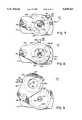
- FIG. 1is a perspective view of an angiographic CT injector embodying principles of the present invention.
- FIG. 1Ais a perspective view of an another form of angiographic injector embodying principles of the present invention.
- FIG. 2is an exploded perspective view of a portion of one preferred embodiment of the injector of FIG. 1.
- FIG. 3is a perspective view of the portion of the injector of FIG. 2.
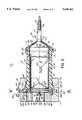
- FIG. 4is a cross-sectional view along lines 4--4 of FIG. 3 illustrating a replaceable syringe unlocked from the housing for insertion into or removal therefrom.
- FIG. 5is a cross-sectional view similar to FIG. 4 but illustrating the syringe locked to the structure carried by the housing.
- FIG. 6is a cross-sectional view along the line 6--6 of FIG. 5.
- FIG. 7is an elevational diagrammatic illustration of the injector of FIG. 1 with the pressure jacket and syringe removed, and showing the syringe locking structure in the locked position such as in FIGS. 5 and 6.
- FIG. 8is an elevational diagrammatic view similar to FIG. 7 illustrating the syringe locking structure in the unlocked position such as in FIGS. 2-4.
- FIG. 9is an elevational diagrammatic view similar to FIG. 7 illustrating the locking mechanism in the housing door release position.
- FIG. 10is a cross-sectional view through the housing of the injector taken along lines 10--10 of FIG. 1A with the plunger drive disengaged from the syringe plunger coupling.
- FIG. 11is a view of a portion of FIG. 10 illustrating the plunger drive longitudinally moving into engagement with the plunger coupling.
- FIG. 12is a view of a portion of FIG. 10 illustrating the plunger drive in engagement with the plunger coupling.
- FIG. 13is a front view of a portion of another embodiment of the injector of FIG. 1.
- FIG. 14is a view of an alternative embodiment of a portion of a syringe according to principles of the present invention.
- FIG. 15is a cross-sectional view similar to FIG. 5 of an alternative embodiment of the invention, illustrating alternative engaging structure between the front ends of the syringe and jacket.
- FIG. 16is a cross-sectional view similar to FIG. 5 of a further alternative embodiment of the invention, also illustrating alternative engaging structure between the front ends of the syringe and jacket.
- FIG. 17is a front end view of still a further alternative embodiment of the invention, also illustrating alternative engaging structure between the front ends of the syringe and jacket.
- an angiographic injector 10configured for CT applications.
- the injector 10includes a ceiling mounted support 11, adjacent a CT X-ray unit, to the lower surface of which is rigidly supported a vertically descending support column 12.
- an injector control module console 13Remote from the support 11 is an injector control module console 13 behind a wall which isolates the operator area from the X-ray equipment.
- the console 13is located adjacent a control 14 of the X-ray equipment. Electrical power and control cables (not shown) communicate power and control signals through the support 11 and the column 12 and to a power lead 15.
- the console 13connects with an injector control module 16, which includes a programmable microprocessor (not shown) to which commands and programming codes are input through a keyboard 17 on the console 13.
- the console 13is also provided with an operator display 18 to aid in interfacing the input commands and injector status with the operator.
- Attached to the column 12is an articulating adjustable arm 19.
- To the remote end of the arm 19is adjustably supported injection module unit 20.
- the arm 19is capable of setting the unit 20 at varying positions adjacent a patient bed of the CT unit.
- the injector 10aincludes a wheeled base 11a to the top of which is rigidly supported a vertically adjustable upstanding support column 12a. To the top of the column 12a is supported a control module platform 13a. Electrical power is communicated from a power cord (not shown) through the base 11a and the upstanding support 12a and through a power lead 15a to a control module 16a rigidly supported to the platform 13a.
- the control module 16aincludes a programmable microprocessor (not shown) to which commands and programming codes are input through a keyboard 17a on the module 16a.
- the module 16ais also provided with an operator display 18a to aid in interfacing the input commands and injector status with the operator.
- Attached to the platform 13ais an articulating adjustable arm 19a. To the remote end of the arm 19a is adjustably supported the injection module unit 20.
- the injection module unit 20 of the embodiments of FIGS. 1 and 1Aincludes a housing 21 which contains the operating drive structure of the injector 10 or 10a.
- the housing 21has a support bracket 23 fixed thereto and adjustably pivotally supported to the remote end 24 of the articulating arm 19 or 19a.
- the housing 21has pivotally attached to the front thereof a door 25 at the front thereof which is pivotally connected to the housing 21 at a longitudinally extending pivot or hinge pin 26 (FIG. 2) rigidly supported on the housing 21 and extending forwardly from the front of the housing 21.
- an injector position and local control panel 27having a position indicator scale 28 thereon, which displays the position of the injector drive to the operator.
- the panel 27also includes a pair of forward and reverse drive direction control buttons 29, which are selectively actuatable to activate a drive within the housing 21 in either the forward or reverse directions.
- the syringe and jacket assembly 30includes a hard plastic pressure jacket 31, which may be of opaque or transparent material, a removable and replaceable disposable syringe 32, which may be of opaque, transparent or semi-transparent material, and related structure hereinafter described.
- the syringe 32is disposable, and includes walls which will withstand only moderate or low pressure.
- the wallsare usually outwardly deformable under operating pressures, particularly pressures of 300 psi or more. Such higher pressures are necessary to overcome pressure drops through the injection tubing at higher flow rates, which are often desirable.
- the jacket 31is made of a stronger transparent material that will withstand the operating pressures. When the syringe 32 is contained in the jacket 31, it is surrounded by the jacket 31 and supported by the jacket 31 against expansion caused by the fluid pressure within as the syringe 32 expands against the jacket wall.
- the pressure jacket 31has a generally cylindrical inner bore 33 extending therethrough from a proximate end 34 adjacent the door 25 to a remote end 35 of the pressure jacket 31 toward the front of the unit 20.
- the bore 33is dimensioned so as to receive through the remote end 35 the disposable syringe 32 and to support the syringe against expansion from fluid pressure within such fluid pressure may range to more than a thousand psi.
- the pressure jacket 31has an annular flange 37 extending outwardly around the proximate end 34.
- the flange 37is integrally formed with the jacket cylinder and is shaped to conform to an annular recess 38 surrounding a circular hole 39 in the door 25 to which the jacket 31 may be assembled by insertion from the rear.
- the hole or opening 39 in the door 25 and the cylindrical bore 33 of the jacket 31are concentric with a longitudinal axis 40 on which also lies an axis 41 of the syringe 32 when the syringe 32 is positioned in the bore 33 of the jacket 31.
- the jacket 31is firmly and rigidly attached to the door 25 with a pair of screws 43, only one of which is shown, which are threaded into a pair of holes 44 in the back of the door 25 (FIG. 2).
- An O-ring seal 46surrounds the flange 37 of the jacket 31 in the recess 38 of the door 25.
- the syringe 32includes a syringe case 50 formed of a single piece of molded plastic material, a pressure cap 51, a tubing collar 52 (FIG. 3) and a plunger 54 (FIGS. 3-5).
- the syringe case 50includes a cylindrical syringe body 55 having an open proximate end 56 and a remote end 58 to which is integrally formed a conical front wall 57.
- the front wall 57is truncated at its forward end, to which is integrally formed an elongated neck 59 extending from the wall 57 at the center thereof.
- the neck 59 of the syringe case 50has an orifice 60 (FIG.
- an external thread 66configured to mate with threads 67 on the interior of collar 52 (FIG. 3).
- the thread 66 in the neck 59has a stop 69 at near forward end thereof to engage an abrupt step 70 on the thread 67 of the collar 52 so that, when the syringe 32 is properly oriented in the jacket 31, the collar 52, when loosened to its maximum extent, will assume a predetermined orientation so as to present, in an upwardly facing orientation, a tube end receiving slot 62 formed in the remote end of the collar 52.
- This slot 62is of T-shaped cross-section so as to receive the enlarged flange end 63 of a tube 65 through which fluid from the syringe cavity 61 is injected into a patient.
- the cap 51is generally conical in shape and has an inner rearward surface 75, which conforms to the front surface of the conical wall 57 of the case 50 of the syringe 32.
- the rearward conical surface 75 of the cap 51may be bonded to the front surface of the conical wall 57 of the case 50 of the syringe 32, or it may be formed integrally therewith, molded from the same plastic material as the case 50 of the syringe 32.
- the cap 51is separate from the syringe body portion 55 and has a pair of holes or detents 76 into which fit a pair of projections 77 extending forwardly from and formed integrally on the outer surface of the conical wall 57 of the case 50 of the syringe 32.
- the cooperation of the pins or projections 77 with the holes or detents 76prevent the cap from rotating with respect to the syringe case 50 when the cap 51 is mounted on the syringe 32.
- the tabs 78are formed about a central inner hole 79 of the cap 51.
- the tabs 78are separated by six equally spaced radial slots 80 (FIG. 3).
- the hole 79 in the cap 51is equal to or only slightly greater in size than the circular forward end of the conical wall 57 of the case 50 of the syringe 32.
- the neck 59 of the syringe 32has an enlarged straight section 81 slightly greater in diameter than the hole 79 in the cap 51 and also greater in diameter than the forward end of the conical wall 57 of the case 50, thereby forming a groove 82 at the juncture of the straight neck portion 81 with the conical wall 57 so that the tips of the tabs 78, which are sufficiently resilient to slide over the enlarged neck portion 81 as the cap 51 is inserted on the case 50 of the syringe 32 with the hole 79 surrounding the neck 59 to snap fit into the groove 82.
- the syringe 32includes structure that is configured to lock the syringe 32 to the front end of the jacket 31 by cooperating with mating structure on the jacket 31.
- the jacket 31has, spaced around the circumference thereof near the remote or front end 35 of the jacket 31, four equally spaced outwardly projecting thread sections 85. These thread sections 85 are slightly less than 45° in extension around the circumference of the jacket 31 and are spaced apart with gaps of slightly greater than 45°.
- the cap 51has a cylindrical rim 87 in which are formed four similarly sized and spaced mating thread sections 86. The thread sections 86 project inwardly toward the jacket 31 when the syringe 32 is positioned in the jacket 31.
- the threads 86 of the cap 51pass through the spaces between the threads 85 on the jacket 31 to a point behind the threads 85.
- the syringe assembly 32 with the cap 51may be twisted clockwise 45° to tighten and thereby secure the cap 51 to the jacket 31 by engagement between the threads 85 and 86 as shown in FIG. 5, to thereby lock the syringe in the bore 33.
- the piston 54 of the syringe 32is molded of an elastomeric material.
- the piston 54includes two portions molded of different materials and bonded together. These portions include a forward more flexible portion 90 in which is formed the forward conical surface 64.
- This forward portion 90has a pair of outwardly extending rings 91 formed in the periphery thereof to make sealing engagement with the inside of the wall of the cylindrical body 55 of the syringe case 50.
- the rearward portion of the piston 54is a flat circular surface to which is bonded the flat circular forward surface of a more rigid rear portion 93 of the piston 54.
- the rear rigid portion 93 of the piston 54is molded of a harder stronger plastic material and has a rearward facing circular surface 95 having a rearward extending coupling 96 integrally formed thereon at its center.
- the coupling 96includes a rearwardly extending cylindrical shaft 97 on the axis 41 of the syringe 32 and a larger symmetrical cylindrical button 98 integrally formed at the rear end of the cylindrical shaft 97.
- the drive assembly 100includes an electric motor 101 mounted within the fixed housing 21 and having a rotary output shaft 102 with a drive gear 103 fixed to the remote end thereof.
- the drive gear 103is positioned for driving engagement with a driven gear 104 fixed near the rear end of a drive screw or shaft 105 supported at its rear end in a bearing 106 fixed in the housing 21.
- the screw or shaft 105has a continuous external helical thread 107 thereon which mates with interior threads of a carriage 108.
- the carriage 108is slidably supported in a bushing 109 fixed in the housing 21.
- the shaft 105rotates within the housing 21 about a longitudinal axis 112.
- a pair of hooked jaws 114which are pivotally mounted at their rearward ends by a pair of pivot pins 115 to the carriage 108.
- the jaws 114are biased toward the axis 112 by a pair of balls 116a and 116b of resilient material positioned between the outside of the jaws 114 and an inner cylindrical wall 117 of a recess 118 formed in the forward end of the carriage 108.
- the balls 116a, 116bare partially captured in depressions in the outer surfaces of the jaws 114.
- the balls 116a, 116bbias the jaws toward their innermost position toward the axis 112.
- the innermost position of the jawsis determined by a spacing block 119 on the axis 112 of the carriage 108 at the center of the cavity 118.
- the plunger 54may be located in the cylindrical body 55 of the syringe case 50 in a position forward of the remote end 56.
- the jaws 114are displaced to the side of axis 112 of the shaft 105 so that as the jaws 114 and coupling tip 98 are in their disengagement position, maximum clearance is provided so that the syringe 32 may be inserted into the jacket 31 without the sterile internal walls of the syringe 31 touching the components of the drive, as illustrated in the figures.
- the jaws 114are nonetheless in alignment with the coupling 98 on the axes 40 and 41 of the jacket 31 and syringe 32.
- the jaws 114may be in a retracted position at the center of the opening 39 of the door 25 adjacent to the proximate end 34 of the jacket 31, and out of engagement with the coupling 96 on the plunger 54. From this position, operation of the motor 101 rotates the shaft 105 and drives the carriage 108 forwardly to move the jaws 114 toward and into engagement with the coupling 96 on the plunger 54. This engagement takes place as shown in FIG.
- Disengagement of the jaws 114 from the coupling 96can thereafter be achieved by translational movement between the coupling 96 and the jaws 114 between a disengaged position as shown in FIG. 4 and an engaged position as shown in FIG. 5.
- the syringe 32can be replaced without the need to retract the carriage 108 of the drive 100. This allows for rapid replacement of the syringe 32.
- the jaws 114are either fully retracted toward the housing 21 where engagement by translation of the coupling 96 will occur, or the jaws 114 are sufficiently within the jacket prior to replacement of the syringe so that the coupling 96 of the replacement syringe 32 will not contact the jaws 114 except as the drive 100 is advanced.
- the most time saving approachwould be to insert the syringe 32 into the jacket 31 with its plunger all the way forward and the drive fully advanced so that, when the syringe is translated toward the jaws 114, engagement will immediately occur and the plunger can be immediately retracted to fill the syringe.
- the coupling 96When a syringe 32 is inserted into the jacket 31 when the plunger 54 is at its rearmost position toward the proximate end 56 of the syringe body 55, the coupling 96 is in a position adjacent the proximate end 56 of the syringe body 55 and projecting rearwardly therebeyond. When in such a position, engagement between the jaws and the coupling 96 is brought about by translational movement between the position shown in FIG. 4 and that shown in FIG. 5. In the unlocked or disengaged position shown in FIG.
- the axis 112 of the shaft 105is slightly eccentric relative to the axes 40 and 41 of the jacket 31 and syringe 32, respectively, as shown in FIG. 5.
- This translational movement, the engagement and disengagement between the coupling 96 and the jaws 114 and the 45° rotational movement which secures the cap 51 to the pressure jacket 31 by engagement of the threads 85 and 86are brought about by operation of a translating and locking mechanism 125, which is best understood by reference to FIGS. 2-9.
- the translating and locking mechanism 125includes a cam and locking ring 127 which is rotatably retained in a circular recess 126 in the back of the door 25.
- the ring 127has a generally semi-circular groove 130 in the back surface thereof for receiving a spring wire retaining clip 131 having a pair of looped ends 133 which extend through a pair of slots 134 in the rim of the ring 127 and into a selected one of three pair of diametrically opposed notches 135, 136 and 137 in the inner wall of the rim of the recess 126 in the door 25.
- the three pair of notches 135, 136 and 137represent three positions of the translating and locking mechanism 125 which are the locked, unlocked and release positions, respectively.
- the ring 127is moved among these three positions by a manually accessible handle 138 in the form of a cylindrical knob 139 rotatably attached to a lever arm 140 formed integrally and extending radially from the ring 127 through a slot 141 in the door 25 (FIG. 2).
- the ring 127is retained in the recess 126 by a pair of screws 143 which thread into countersunk holes 144 at the periphery of the recess 126 in the back of the door 25. These screws 143 have enlarged heads 146, which, when seated in the holes 144, overlie the edge of the ring 127, thereby securing it for rotatable movement within the recess 126.
- the ring 127has an inner periphery 149 which is larger than the circumference of the body 55 of the syringe case 50. Accordingly, when the syringe 32 is inserted in the jacket 31, the proximate end 56 of the syringe case 50 extends through and is surrounded by the inner periphery 149 of the ring 127.
- Asymmetric keyway structurepreferably in the form of three slots or notches 151, 152 and 153 (FIG. 6) are provided in the edge of the proximate end 56 of the body 55 of the syringe case 50. The spacings between adjacent pairs of the notches 151-153 differ from each other.
- tabs or keys 155, 156 and 157are spaced so as to fit into the respective notches 151-153 in the proximate end 56 of the body 55 of the syringe case 50 so as to rotate the syringe 32 as the mechanism 125 is rotated through actuation of the handle 138. Because the notches 151-153 and the tabs 155-157 are unequally spaced, they can only engage each other when the syringe 32 is inserted into the jacket 31 in one and only one orientation. That orientation is one which will cause the slot 62 of the collar 52 (FIG.
- the rotation of the mechanism 125 from the unlocked position to the locked positionrotates the syringe 32 in the jacket 31 and rotates the cap such that its threads move from an unlocked position as shown in FIG. 4 to the locked position of FIG. 5, to secure the cap to the jacket 31 by the engagement and tightening of the threads 85 and 86.
- the translational movement of the axes 40 and 41 with respect to the axis 112is achieved by a fixed cylindrical cam follower or pin 150 which projects outwardly from the fixed housing portion 22 behind the ring 127 and into a cam slot 154 formed therein.
- the slot 154is shaped so that the axes 40 and 41 which remain fixed with respect to the ring 127, along with the door 25, the jacket 31, the syringe 32 and all of the structure mutually carried thereby, are moved in relation to the axis 112 of the shaft 105 and the other structure mutually carried by the housing 21, as the mechanism 125 is rotated.
- These axesmove toward and away from each other in accordance with the shape of the slot 154 determined by the radial distance from the point along the slot 154 where it engages the pin 150 to the axes 40 and 41.
- the cam slot 154 in the ring 127is shaped such that, when the mechanism 125 is in the locked position as shown, for example, in FIGS. 6 and 7, the distance between the pin 150 and the axes 40 and 41 is at a minimum and the axis 112 coincides with the axes 40 and 41. This is illustrated in FIGS. 5 and 7 wherein the coupling 96 is shown positioned between the jaws 114 and in mutual engagement therewith.
- the mechanism 125is in the unlocked position, with the loops 133 of clip 131 in the notches 135 (FIG. 6) of the recess 126, the pin 150 lies in the slot 154 in the position shown in FIG. 8, which is farther displaced from the axes 40 and 41 than in the position of FIGS. 6 and 7, so that the coupling 96 is translated to a position outside of the center line of the jaws 114, as shown in FIG. 8 and further illustrated in FIG. 4.
- the pin 150is positioned at the open end 160 of the cam surface of the slot 154 so that the door 25 can be rotated upwardly about the hinge pin 26, as shown in FIG. 9, to open the space behind the door 25 for access thereto.
- This positionmay be used for cleaning the area behind the door 25 which is sometimes necessary because of possible leakage of fluid from the cavity 61 into the space behind the plunger 54.
- the fluid within the cavity 61when being injected by forward advancement of the plunger 54, may be of relatively high pressure in the range, usually over 200 psi.
- pressuremay typically be in the range of from 25 to 300 psi., while in some angiographic injection applications the pressure may range to 1200 psi or higher.
- the cap 51is caused to fit snugly against the forward surface of the conical portion 57 of the syringe 32 at least sufficiently to restrict the flow of this leaking fluid onto the neck 59. This is assisted by the configuration of the cap 51 at the rim 87 thereof so as to divert away from the space between the syringe 32 and jacket 31 fluid which might leak from the nozzle.
- the front of the housing 21has formed thereon a door stop 185 having a slot 186 formed therein for receiving a lug 187 of the door 25, to restrain the door 25 against forward force exerted by the drive 100.
- a magnetic sensor 188Behind the front of the housing 21 adjacent the stop 185 is a magnetic sensor 188, which is responsive to the presence of a magnet 189 in the lever arm 139 of the handle 138. The sensor 188 generates a signal to the control module 16 to activate the drive 100 only when the mechanism 125 is in its locked position.
- a locking mechanism 225that is an alternative to the locking mechanism 125 described above.
- a stationary geared rack 250is provided fixed to the housing 21.
- a mating gear segment 254is formed on the outer rim of the alternative locking ring 227 of this embodiment.
- the gear segment 254 and rack 250replace and function in the same way as the slot 154 and pin 150 of the embodiment described above.
- the syringe 32is rotated in the jacket 31 to lock or unlock the syringe 32 to the jacket 31 by engagement or disengagement of the threads 86 on the syringe 32 with the threads 85 on the jacket 32.
- FIG. 14illustrates an alternative to the embodiment of the coupling 96 described above.
- a coupling 296that is T-shaped, having a rectangular endpiece 298 at the rearward end of a cylindrical or square shaft 297 on the rearwardly facing circular surface 95 of the plunger 54.
- Such a coupling 296engages the jaws 114 by rotation of the locking mechanism 125 or 225, preferably through an angle of 90°.
- orientation of the syringe 32, when loaded into the jacket 31,is preferably maintained through the cooperation of the notches 151-153 and the tabs 154-156 (FIG. 4), so that the coupling 296 will enter the jaws 114, when the syringe 32 is inserted into the jacket 31, with the endpiece 298 perpendicular to the pair of jaws 114.
- the locking structure between the syringe 32 and the pressure jacket 31should provide for retention of the syringe 32 in the jacket 31 against the force of the fluid pressure in the cavity 61 or axial force otherwise exerted on the plunger 54 by the drive 100.
- This locking of the syringe 32 to the jacket 31is preferably achieved, as shown in FIG. 5, by structure at or near the forward wall 57 of the syringe case 50.
- such structuremay include external threads 200 formed of four equally spaced, radially outwardly directed thread sections (flanges), each spanning slightly less than 45° about syringe body 257, and positioned (monolithic with) the forward end of the syringe body 257, which mate with internal threads 201 formed of four equally spaced, radially inwardly directed mating thread sections (flangs), each spanning slightly less than 45° about jacket 31, positioned around the opening at the remote end of the tubular cylindrical pressure jacket 31.
- flangesradially outwardly directed thread sections
- the syringe 32is preferably provided with continuous, planar annular ring-shaped flange 203 around (monolithic with) the body 257 at the juncture of the body 257 with the syringe front wall 258.
- Threads 200 and 201form a connector, specifically, a screw or twist lock whereby syringe 32 may be rotated or twisted 45° to lock syringe 32 to the injector.
- the flange 203inhibits the flow of leaked fluid into the space between the syringe body 257 and a peripheral rim of the jacket 31.
- the wall 258is either thickened, provided with reinforcing such as the ribs 208, or provided with other structure to resist deformation of the wall 258 under the pressure of the fluid within the cavity 61.
- a reusable split clip 210may be employed to secure a continuous flange 203 of such a syringe to a continuous flange 212 at the end of the pressure jacket in the embodiment of FIG. 16.
- a ring clip 210ahaving an outer rim 215 and rotatably mounted to the jacket 31, encircles and engages outwardly projecting threads 203a of a disk flange 213 formed at the front end of the syringe 32 to engage the jacket in a manner similar to the threads 85 and 86 in the embodiment of FIGS. 2-12 above.
Landscapes
- Health & Medical Sciences (AREA)
- Vascular Medicine (AREA)
- Engineering & Computer Science (AREA)
- Anesthesiology (AREA)
- Biomedical Technology (AREA)
- Heart & Thoracic Surgery (AREA)
- Hematology (AREA)
- Life Sciences & Earth Sciences (AREA)
- Animal Behavior & Ethology (AREA)
- General Health & Medical Sciences (AREA)
- Public Health (AREA)
- Veterinary Medicine (AREA)
- Infusion, Injection, And Reservoir Apparatuses (AREA)
- Housing For Livestock And Birds (AREA)
Abstract
Description
Claims (37)
Priority Applications (1)
| Application Number | Priority Date | Filing Date | Title |
|---|---|---|---|
| US08/417,823US5658261A (en) | 1991-06-07 | 1995-04-06 | Disposable front loadable syringe |
Applications Claiming Priority (3)
| Application Number | Priority Date | Filing Date | Title |
|---|---|---|---|
| US07/712,110US5300031A (en) | 1991-06-07 | 1991-06-07 | Apparatus for injecting fluid into animals and disposable front loadable syringe therefor |
| US08/195,382US5451211A (en) | 1991-06-07 | 1994-02-14 | Disposable front loadable syringe for power injector for injecting fluid into animals |
| US08/417,823US5658261A (en) | 1991-06-07 | 1995-04-06 | Disposable front loadable syringe |
Related Parent Applications (1)
| Application Number | Title | Priority Date | Filing Date |
|---|---|---|---|
| US08/195,382DivisionUS5451211A (en) | 1991-06-07 | 1994-02-14 | Disposable front loadable syringe for power injector for injecting fluid into animals |
Publications (1)
| Publication Number | Publication Date |
|---|---|
| US5658261Atrue US5658261A (en) | 1997-08-19 |
Family
ID=24860794
Family Applications (11)
| Application Number | Title | Priority Date | Filing Date |
|---|---|---|---|
| US07/712,110Expired - LifetimeUS5300031A (en) | 1991-06-07 | 1991-06-07 | Apparatus for injecting fluid into animals and disposable front loadable syringe therefor |
| US07/881,782Expired - LifetimeUS5279569A (en) | 1991-06-07 | 1992-05-11 | Front loading apparatus for insecting fluid into animals |
| US08/158,765Expired - LifetimeUS5456669A (en) | 1991-06-07 | 1993-11-30 | Method of front loading an injector and injecting fluid into animals therewith |
| US08/195,382Expired - LifetimeUS5451211A (en) | 1991-06-07 | 1994-02-14 | Disposable front loadable syringe for power injector for injecting fluid into animals |
| US08/205,710Expired - LifetimeUS5456670A (en) | 1991-06-07 | 1994-03-03 | Power injector for injecting fluid into animals |
| US08/417,823Expired - LifetimeUS5658261A (en) | 1991-06-07 | 1995-04-06 | Disposable front loadable syringe |
| US08/455,984Expired - Fee RelatedUS5738659A (en) | 1991-06-07 | 1995-05-31 | Method of injecting fluid into animals |
| US08/924,017Expired - Fee RelatedUS6315758B1 (en) | 1991-06-07 | 1997-08-29 | Method of injecting fluid into animals |
| US09/970,289Expired - Fee RelatedUS6659979B2 (en) | 1991-06-07 | 2001-10-02 | Method of injecting fluid into animals |
| US10/730,302Expired - Fee RelatedUS7081104B2 (en) | 1991-06-07 | 2003-12-08 | Method and apparatus for injecting fluid into animals and disposable front loadable syringe therefor |
| US11/458,283AbandonedUS20060264744A1 (en) | 1991-06-07 | 2006-07-18 | Method and Apparatus for Injecting Fluid into Animals and Disposable Front Loadable Syringe Therefor |
Family Applications Before (5)
| Application Number | Title | Priority Date | Filing Date |
|---|---|---|---|
| US07/712,110Expired - LifetimeUS5300031A (en) | 1991-06-07 | 1991-06-07 | Apparatus for injecting fluid into animals and disposable front loadable syringe therefor |
| US07/881,782Expired - LifetimeUS5279569A (en) | 1991-06-07 | 1992-05-11 | Front loading apparatus for insecting fluid into animals |
| US08/158,765Expired - LifetimeUS5456669A (en) | 1991-06-07 | 1993-11-30 | Method of front loading an injector and injecting fluid into animals therewith |
| US08/195,382Expired - LifetimeUS5451211A (en) | 1991-06-07 | 1994-02-14 | Disposable front loadable syringe for power injector for injecting fluid into animals |
| US08/205,710Expired - LifetimeUS5456670A (en) | 1991-06-07 | 1994-03-03 | Power injector for injecting fluid into animals |
Family Applications After (5)
| Application Number | Title | Priority Date | Filing Date |
|---|---|---|---|
| US08/455,984Expired - Fee RelatedUS5738659A (en) | 1991-06-07 | 1995-05-31 | Method of injecting fluid into animals |
| US08/924,017Expired - Fee RelatedUS6315758B1 (en) | 1991-06-07 | 1997-08-29 | Method of injecting fluid into animals |
| US09/970,289Expired - Fee RelatedUS6659979B2 (en) | 1991-06-07 | 2001-10-02 | Method of injecting fluid into animals |
| US10/730,302Expired - Fee RelatedUS7081104B2 (en) | 1991-06-07 | 2003-12-08 | Method and apparatus for injecting fluid into animals and disposable front loadable syringe therefor |
| US11/458,283AbandonedUS20060264744A1 (en) | 1991-06-07 | 2006-07-18 | Method and Apparatus for Injecting Fluid into Animals and Disposable Front Loadable Syringe Therefor |
Country Status (10)
| Country | Link |
|---|---|
| US (11) | US5300031A (en) |
| EP (3) | EP0749757A3 (en) |
| JP (1) | JP3324752B2 (en) |
| KR (1) | KR100203963B1 (en) |
| AT (1) | ATE214953T1 (en) |
| AU (1) | AU1277192A (en) |
| CA (1) | CA2103352C (en) |
| DE (2) | DE749757T1 (en) |
| ES (1) | ES2171397T5 (en) |
| WO (2) | WO1992021391A1 (en) |
Cited By (41)
| Publication number | Priority date | Publication date | Assignee | Title |
|---|---|---|---|---|
| US5925022A (en)* | 1996-11-22 | 1999-07-20 | Liebel-Flarsheim Company | Medical fluid injector |
| USD426892S (en) | 1999-06-29 | 2000-06-20 | Medrad, Inc. | Medical injector |
| USD426891S (en)* | 1999-06-29 | 2000-06-20 | Medrad, Inc. | Injector head for a medical injector |
| USD426884S (en)* | 1998-07-08 | 2000-06-20 | Chad Srisathapat | Syringe plunger |
| USD428491S (en)* | 1999-06-29 | 2000-07-18 | Medrad, Inc. | Combined handle and display for a medical injector |
| US6090064A (en)* | 1992-08-17 | 2000-07-18 | Medrad, Inc. | Front loading medical injector and syringe for use therewith |
| US6196999B1 (en) | 1999-02-05 | 2001-03-06 | Liebel-Flarsheim Company | Syringe/plunger coupling |
| US6402718B1 (en) | 1992-08-17 | 2002-06-11 | Medrad, Inc. | Front-loading medical injector and syringe for use therewith |
| US20020160993A1 (en)* | 2000-12-29 | 2002-10-31 | Egan John J. | Method for treating glaucoma IC |
| US6589158B2 (en)* | 1999-08-06 | 2003-07-08 | Proxima Therapeutics, Inc. | Radiation shield for a syringe |
| US6652489B2 (en) | 2000-02-07 | 2003-11-25 | Medrad, Inc. | Front-loading medical injector and syringes, syringe interfaces, syringe adapters and syringe plungers for use therewith |
| US6652493B1 (en)* | 2000-07-05 | 2003-11-25 | Animas Corporation | Infusion pump syringe |
| US20040030247A1 (en)* | 2002-03-13 | 2004-02-12 | Mark Trocki | Apparatus, systems and methods for facilitating multiple imaging procedures for a patient |
| US6699214B2 (en) | 2000-01-19 | 2004-03-02 | Scimed Life Systems, Inc. | Shear-sensitive injectable delivery system |
| US6958053B1 (en) | 1999-11-24 | 2005-10-25 | Medrad, Inc. | Injector providing drive member advancement and engagement with syringe plunger, and method of connecting a syringe to an injector |
| US20060106347A1 (en)* | 2004-11-17 | 2006-05-18 | Liebel-Flarsheim Company | Disposable front loadable syringe and injector |
| US20070173770A1 (en)* | 2006-01-23 | 2007-07-26 | The Medical House Plc | Injection device |
| US7419478B1 (en) | 2003-06-25 | 2008-09-02 | Medrad, Inc. | Front-loading syringe for medical injector having a flexible syringe retaining ring |
| WO2009023463A1 (en) | 2007-08-13 | 2009-02-19 | Mallinckrodt Inc. | Drive ram for medical injectors |
| US7553294B2 (en) | 2002-05-30 | 2009-06-30 | Medrad, Inc. | Syringe plunger sensing mechanism for a medical injector |
| US7635356B2 (en) | 2004-01-23 | 2009-12-22 | The Medical House, Plc | Injection device |
| US20100063390A1 (en)* | 2007-04-11 | 2010-03-11 | Fago Frank M | Universal syringe |
| US20100130930A1 (en)* | 2007-03-07 | 2010-05-27 | The Medical House Plc | autoinjector |
| US20100152655A1 (en)* | 2006-01-23 | 2010-06-17 | The Medical House Plc | Improved autoinjector supporting the syringe at the front |
| US8734393B2 (en) | 2009-04-23 | 2014-05-27 | The Medical House Limited | Autoinjector |
| US8747357B2 (en) | 2006-12-18 | 2014-06-10 | The Medical House Limited | Autoinjector |
| US8945051B2 (en) | 2009-07-24 | 2015-02-03 | Bayer Medical Care Inc. | Multi-fluid medical injector system and methods of operation |
| US9108047B2 (en) | 2010-06-04 | 2015-08-18 | Bayer Medical Care Inc. | System and method for planning and monitoring multi-dose radiopharmaceutical usage on radiopharmaceutical injectors |
| US9480797B1 (en) | 2015-10-28 | 2016-11-01 | Bayer Healthcare Llc | System and method for syringe plunger engagement with an injector |
| US9694131B2 (en) | 2003-11-25 | 2017-07-04 | Bayer Healthcare Llc | Medical injector system |
| US9744305B2 (en) | 2012-09-28 | 2017-08-29 | Bayer Healthcare Llc | Quick release plunger |
| US9844622B2 (en) | 2000-07-10 | 2017-12-19 | Bayer Healthcare Llc | Syringes for medical injector systems |
| US9855390B2 (en) | 2006-03-15 | 2018-01-02 | Bayer Healthcare Llc | Plunger covers and plungers for use in syringes |
| USD847985S1 (en) | 2007-03-14 | 2019-05-07 | Bayer Healthcare Llc | Syringe plunger cover |
| US10806852B2 (en) | 2014-03-19 | 2020-10-20 | Bayer Healthcare Llc | System for syringe engagement to an injector |
| USD942005S1 (en) | 2007-03-14 | 2022-01-25 | Bayer Healthcare Llc | Orange syringe plunger cover |
| USD1002840S1 (en) | 2007-03-14 | 2023-10-24 | Bayer Healthcare Llc | Syringe plunger |
| US11883636B2 (en) | 2018-02-27 | 2024-01-30 | Bayer Healthcare Llc | Syringe plunger engagement mechanism |
| US11969582B2 (en) | 2017-01-06 | 2024-04-30 | Bayer Healthcare Llc | Syringe plunger with dynamic seal |
| US11998718B2 (en) | 2020-06-18 | 2024-06-04 | Bayer Healthcare Llc | System and method for syringe plunger engagement with an injector |
| USD1031029S1 (en) | 2003-11-25 | 2024-06-11 | Bayer Healthcare Llc | Syringe plunger |
Families Citing this family (244)
| Publication number | Priority date | Publication date | Assignee | Title |
|---|---|---|---|---|
| US5300031A (en)* | 1991-06-07 | 1994-04-05 | Liebel-Flarsheim Company | Apparatus for injecting fluid into animals and disposable front loadable syringe therefor |
| US5383906A (en)* | 1993-05-12 | 1995-01-24 | Burchett; Mark T. | Nursing bottle with medication dispenser |
| US5579767A (en)* | 1993-06-07 | 1996-12-03 | Prince; Martin R. | Method for imaging abdominal aorta and aortic aneurysms |
| US5590654A (en) | 1993-06-07 | 1997-01-07 | Prince; Martin R. | Method and apparatus for magnetic resonance imaging of arteries using a magnetic resonance contrast agent |
| US5417213A (en)* | 1993-06-07 | 1995-05-23 | Prince; Martin R. | Magnetic resonance arteriography with dynamic intravenous contrast agents |
| USD360462S (en) | 1993-09-22 | 1995-07-18 | Sterling Winthrop Inc. | Hand-held power syringe |
| CA2129284C (en)* | 1993-11-24 | 1999-03-09 | Kenneth J. Niehoff | Controlling plunger drives for fluid injection in animals |
| US5494036A (en)* | 1993-11-26 | 1996-02-27 | Medrad, Inc. | Patient infusion system for use with MRI |
| DK0665027T3 (en)* | 1994-01-28 | 2000-04-03 | Mallinckrodt Medical Gmbh | Conversion kit for an injection machine for use with syringes of different diameters |
| US5535746A (en)* | 1994-03-29 | 1996-07-16 | Sterling Winthrop Inc. | Prefilled syringe for use with power injector |
| US5779675A (en)* | 1995-08-25 | 1998-07-14 | Medrad, Inc. | Front load pressure jacket system with syringe holder |
| US5520653A (en)* | 1995-09-01 | 1996-05-28 | Medrad, Inc. | Syringe adapter for front-loading medical injector |
| JP3429922B2 (en)* | 1995-10-30 | 2003-07-28 | スーガン株式会社 | Auxiliary device for syringe fixation |
| AU2551097A (en)* | 1996-03-29 | 1997-10-22 | Robert J. Ashcraft Jr. | Front-loading syringe adapter for front-loading medical injector |
| ES2126483B1 (en)* | 1996-04-23 | 1999-11-16 | Iul S A | BIOLOGICAL SAMPLE INOCULATION SYSTEM IN THE AGAR SURFACE IN PETRI CAPSULES. |
| US5873861A (en)* | 1996-11-12 | 1999-02-23 | Medrad, Inc. | Plunger systems |
| US5947935A (en)* | 1996-11-12 | 1999-09-07 | Medrad, Inc. | Syringes, syringe plungers and injector systems |
| DE69733769T2 (en)* | 1996-11-12 | 2006-01-12 | Medrad, Inc. | PREPARED SPRAYING, AS WELL AS INJECTORS TO BE USED WITH IT |
| US5944694A (en)* | 1996-11-12 | 1999-08-31 | Medrad, Inc. | Prefillable syringes and injectors for use therewith |
| USD391638S (en) | 1996-11-22 | 1998-03-03 | Liebel-Flarsheim Company | Electronically controlled contrast media injector for medical diagnostic imaging |
| US5855568A (en)* | 1996-11-22 | 1999-01-05 | Liebel-Flarsheim Company | Angiographic syringe and luer connector |
| USD392388S (en) | 1996-11-26 | 1998-03-17 | Liebel-Flarsheim Company | Electronically controlled contrast media injector for medical diagnostic imaging |
| US6235022B1 (en) | 1996-12-20 | 2001-05-22 | Cardiac Pathways, Inc | RF generator and pump apparatus and system and method for cooled ablation |
| US5913844A (en)* | 1997-06-17 | 1999-06-22 | Liebel-Flarsheim Company | Power injector and method providing removal of used disposable syringe |
| US5865805A (en)* | 1997-07-16 | 1999-02-02 | Liebel-Flarsheim Company | Power injector and side loadable syringe support therefor for plunger pushrod type syringes |
| US9308316B1 (en) | 1997-07-18 | 2016-04-12 | Liebel-Flarsheim Company Llc | Adapter and syringe for front-loading medical fluid injector |
| US6569127B1 (en) | 1997-07-18 | 2003-05-27 | Liebel-Flarsheim Company | Adapter and syringe for front-loading medical fluid injector |
| US6368307B1 (en) | 1997-07-18 | 2002-04-09 | Liebel-Flarsheim Company | Front-loading power injector and method of loading flanged syringe therein |
| US6533758B1 (en) | 1997-07-18 | 2003-03-18 | Liebel-Flarsheim Company | Adapter and syringe for front-loading medical fluid injector |
| US6764466B1 (en) | 1997-07-18 | 2004-07-20 | Liebel Flarsheim Company | Adapter and syringe for front-loading medical fluid injector |
| US5947929A (en)* | 1997-08-22 | 1999-09-07 | Coeur Laboratories, Inc. | Front-load angiographic injector system, angiographic syringe and plunger for angiographic syringe |
| US6080136A (en)* | 1998-06-11 | 2000-06-27 | Polyten Plastics, Llc | Angiographic syringe adapter for front-loading injector |
| US5924987A (en)* | 1997-10-06 | 1999-07-20 | Meaney; James F. M. | Method and apparatus for magnetic resonance arteriography using contrast agents |
| US6016800A (en)* | 1997-10-24 | 2000-01-25 | Century; Theodore J. | Intrapulmonary aerosolizer |
| EP0919251B1 (en) | 1997-11-26 | 2007-01-17 | Liebel-Flarsheim Company | Front-loading power injector and method of loading flanged syringe therein |
| US6726650B2 (en) | 1997-12-04 | 2004-04-27 | Bracco Research S.A. | Automatic liquid injection system and method |
| US6224577B1 (en) | 1998-03-02 | 2001-05-01 | Medrad, Inc. | Syringes and plungers for use therein |
| US6139529A (en)* | 1998-07-07 | 2000-10-31 | Junior; Alceu Meibach Rosa | Advanced anesthetic method |
| US6488661B1 (en) | 1998-07-31 | 2002-12-03 | Medrad, Inc. | Pressure control systems for medical injectors and syringes used therewith |
| EP1105175A1 (en)* | 1998-08-21 | 2001-06-13 | Medrad Inc. | Connector and tubing assembly for use with a syringe |
| US20020173748A1 (en)* | 1998-10-29 | 2002-11-21 | Mcconnell Susan | Reservoir connector |
| CA2345439C (en)* | 1998-10-29 | 2005-08-09 | Minimed, Inc. | Compact pump drive system |
| US6620134B1 (en) | 1998-11-23 | 2003-09-16 | Medrad, Inc. | Syringes and injector systems with collapsible cartridges |
| US6635030B1 (en) | 1999-04-09 | 2003-10-21 | B.H.B. Llc | Contrast injector for injecting a contrast medium to generate prolonged uniform vascular enhancement |
| US6055985A (en) | 1999-04-09 | 2000-05-02 | B.H.B., L.C. | Methods for injecting a contrast medium to generate prolonged uniform vascular enhancement |
| US6301866B1 (en)* | 1999-07-14 | 2001-10-16 | Black & Decker Inc. | Vegetation trimming and edging device with adjustable head orientation |
| US6223941B1 (en)* | 1999-07-19 | 2001-05-01 | The Boeing Company | Applicator for dispensing a soft package of material |
| WO2001008727A1 (en)* | 1999-07-30 | 2001-02-08 | Medrad, Inc. | Injector systems and syringe adapters for use therewith |
| US6520928B1 (en) | 1999-08-19 | 2003-02-18 | Alceu Meibach Rosa Junior | Medical liquid injection system and method |
| USD452737S1 (en) | 1999-10-13 | 2002-01-01 | Medrad, Inc. | Medical injector |
| US6285155B1 (en) | 1999-10-29 | 2001-09-04 | Abbott Laboratories | Pseudo half-step motor drive method and apparatus |
| CA2389521A1 (en)* | 1999-11-05 | 2001-05-17 | Showa Yakuhin Kako Co., Ltd. | Receiving tube mounting device of cartridge type injection device for dental use |
| MXPA02005099A (en) | 1999-11-24 | 2002-11-07 | Medrad Inc | Front-loading medical injector and syringe. |
| US6673033B1 (en) | 1999-11-24 | 2004-01-06 | Medrad, Inc. | Injectors, injector systems and injector control |
| US6520930B2 (en) | 1999-11-24 | 2003-02-18 | Medrad, Inc. | Injectors, injector systems and injector control |
| KR100577410B1 (en)* | 1999-11-30 | 2006-05-08 | 엘지.필립스 엘시디 주식회사 | X-ray image sensing device and its manufacturing method |
| US20030176838A1 (en)* | 1999-12-06 | 2003-09-18 | Medrad, Inc. | Syringes, syringe tubing and fluid transfer systems |
| AU1816701A (en) | 1999-12-07 | 2001-06-18 | Medrad, Inc. | Syringes, syringe tubing and fluid transfer systems |
| JP4593714B2 (en)* | 2000-02-10 | 2010-12-08 | 株式会社根本杏林堂 | Syringe outer cylinder, syringe holder, syringe piston and piston holder |
| US6395006B1 (en)* | 2000-02-14 | 2002-05-28 | Telios Orthopedic Systems, Inc | Connector assembly for mating components, connector assembly for a bone cement mixing and delivery system, and bone cement container having a connector assembly |
| US6723076B1 (en) | 2000-03-24 | 2004-04-20 | Michael Strobel | Animal drug delivery device |
| US6558352B1 (en)* | 2000-05-30 | 2003-05-06 | Verilogik, Inc. | System and method for variable dosage medicine delivery |
| US6704592B1 (en) | 2000-06-02 | 2004-03-09 | Medrad, Inc. | Communication systems for use with magnetic resonance imaging systems |
| US6432089B1 (en) | 2000-06-21 | 2002-08-13 | Medrad, Inc. | Medical syringe |
| CN104941034A (en)* | 2000-07-10 | 2015-09-30 | 拜耳医疗保健公司 | Improved medical injector system |
| ATE551085T1 (en)* | 2000-07-20 | 2012-04-15 | Acist Medical Sys Inc | SYRINGE Plunger LOCKING MECHANISM |
| US7008535B1 (en) | 2000-08-04 | 2006-03-07 | Wayne State University | Apparatus for oxygenating wastewater |
| US6585700B1 (en) | 2000-10-05 | 2003-07-01 | Medrad, Inc. | Syringe, syringe plunger and attachment mechanism for front loading medical injector |
| US6387077B1 (en) | 2000-10-13 | 2002-05-14 | Mallinckrodt Inc. | Apparatus and method for providing a suspended agent |
| US7094216B2 (en)* | 2000-10-18 | 2006-08-22 | Medrad, Inc. | Injection system having a pressure isolation mechanism and/or a handheld controller |
| CN1286536C (en)* | 2001-01-18 | 2006-11-29 | 梅德拉股份有限公司 | Syringe holder for medical injector |
| WO2002066100A2 (en)* | 2001-02-20 | 2002-08-29 | Medrad, Inc. | Syringes, connectors, and syringe and connector systems for use in fluid delivery systems |
| EP1815879A3 (en) | 2001-05-18 | 2007-11-14 | Deka Products Limited Partnership | Infusion set for a fluid pump |
| US7306578B2 (en)* | 2002-01-04 | 2007-12-11 | Deka Products Limited Partnership | Loading mechanism for infusion pump |
| US8034026B2 (en) | 2001-05-18 | 2011-10-11 | Deka Products Limited Partnership | Infusion pump assembly |
| US7563249B2 (en)* | 2002-12-20 | 2009-07-21 | Medrad, Inc. | Syringe having an alignment flange, an extending lip and a radial expansion section of reduced wall thickness |
| US7549977B2 (en)* | 2002-12-20 | 2009-06-23 | Medrad, Inc. | Front load pressure jacket system with syringe holder and light illumination |
| US20080154214A1 (en)* | 2006-12-22 | 2008-06-26 | Medrad, Inc. | Flow Based Pressure Isolation and Fluid Delivery System Including Flow Based Pressure Isolation |
| GB0129187D0 (en)* | 2001-12-06 | 2002-01-23 | Dca Design Int Ltd | Improvements in and relating to a medicament cartridge |
| US20030163089A1 (en)* | 2002-02-28 | 2003-08-28 | Bynum Gail Beth | Child safety cap for syringe pump |
| US7041082B2 (en)* | 2002-02-28 | 2006-05-09 | Smiths Medical Md, Inc. | Syringe pump control systems and methods |
| US7033338B2 (en)* | 2002-02-28 | 2006-04-25 | Smiths Medical Md, Inc. | Cartridge and rod for axially loading medication pump |
| US6929619B2 (en)* | 2002-08-02 | 2005-08-16 | Liebel-Flarshiem Company | Injector |
| US7527608B2 (en) | 2002-08-12 | 2009-05-05 | Lma North America, Inc. | Medication infusion and aspiration system and method |
| USD507834S1 (en)* | 2002-09-30 | 2005-07-26 | Medex | Medical injector |
| US20050015057A1 (en)* | 2002-11-28 | 2005-01-20 | Soren Steenfeldt-Jensen | Cylindrical piston press foot |
| US7192416B1 (en) | 2002-12-20 | 2007-03-20 | Medrad, Inc. | Front load pressure jacket system with grooved syringe holder |
| US7361156B2 (en)* | 2002-12-20 | 2008-04-22 | Medrad, Inc. | Pressure jacket system with pivotal locking members |
| US20040143223A1 (en)* | 2003-01-17 | 2004-07-22 | Spinello Ronald P. | Dental anesthetic injection apparatus and methods for administering dental injections |
| JP4286019B2 (en)* | 2003-02-04 | 2009-06-24 | 株式会社根本杏林堂 | Chemical injection system |
| US7096796B2 (en)* | 2003-02-28 | 2006-08-29 | Honeywell International Inc. | Brake handle with integral position sensing switch |
| US20040168539A1 (en)* | 2003-02-28 | 2004-09-02 | Honeywell International Inc. | Brake handle with integral position sensing |
| US7390314B2 (en) | 2003-03-05 | 2008-06-24 | Medtronic Minimed, Inc. | Lead screw driven reservoir with integral plunger nut and method of using the same |
| US6918907B2 (en)* | 2003-03-13 | 2005-07-19 | Boston Scientific Scimed, Inc. | Surface electrode multiple mode operation |
| US20040181214A1 (en)* | 2003-03-13 | 2004-09-16 | Garabedian Robert J. | Passively cooled array |
| US7938828B2 (en)* | 2003-03-28 | 2011-05-10 | Boston Scientific Scimed, Inc. | Cooled ablation catheter |
| FR2853247B1 (en) | 2003-04-02 | 2006-01-27 | Sedat | IMPROVED ANGIOGRAPHIC SYRINGE SUPPORT DEVICE |
| US7101387B2 (en) | 2003-04-30 | 2006-09-05 | Scimed Life Systems, Inc. | Radio frequency ablation cooling shield |
| WO2004096313A2 (en) | 2003-04-30 | 2004-11-11 | Coeur, Inc | Syringe adapter |
| US20040267272A1 (en)* | 2003-05-12 | 2004-12-30 | Henniges Bruce D | Bone cement mixing and delivery system |
| JP4338447B2 (en)* | 2003-06-06 | 2009-10-07 | 株式会社根本杏林堂 | Chemical injection system |
| US20050080410A1 (en)* | 2003-10-14 | 2005-04-14 | Scimed Life Systems, Inc. | Liquid infusion apparatus for radiofrequency tissue ablation |
| US7850640B2 (en)* | 2003-11-26 | 2010-12-14 | Acist Medical Systems, Inc. | Device, method, and computer program product for dispensing media as part of a medical procedure |
| US7347859B2 (en) | 2003-12-18 | 2008-03-25 | Boston Scientific, Scimed, Inc. | Tissue treatment system and method for tissue perfusion using feedback control |
| US7621892B2 (en)* | 2003-12-31 | 2009-11-24 | Mallinckrodt Inc. | Contrast container holder and method to fill syringes |
| US20050148867A1 (en)* | 2003-12-31 | 2005-07-07 | Liebel-Flarsheim Company | Injector with changeable syringe constants |
| US7282051B2 (en)* | 2004-02-04 | 2007-10-16 | Boston Scientific Scimed, Inc. | Ablation probe for delivering fluid through porous structure |
| EP1725281B1 (en)* | 2004-03-19 | 2008-05-21 | Medtronic MiniMed, Inc. | Lead screw driven syringe with an integral split plunger nut and method of using the same |
| US7556619B2 (en) | 2004-04-16 | 2009-07-07 | Medrad, Inc. | Fluid delivery system having a fluid level sensor and a fluid control device for isolating a patient from a pump device |
| US7815606B2 (en)* | 2004-04-23 | 2010-10-19 | Coeur, Inc. | Syringe adapter system and method of cleaning the adapter |
| US7588559B2 (en)* | 2004-07-01 | 2009-09-15 | W&H Dentalwerk Bürmoos GmbH | Injection systems |
| US7824425B2 (en)* | 2004-08-02 | 2010-11-02 | Biolchini Jr Robert F | Ambidextrous locking clamp system |
| US7758609B1 (en)* | 2004-08-02 | 2010-07-20 | Biolchini Jr Robert F | Ambidextrous locking clamp |
| US20060069350A1 (en)* | 2004-09-30 | 2006-03-30 | Buenger David R | Medical syringe injector pen |
| US20060069354A1 (en)* | 2004-09-30 | 2006-03-30 | Buenger David R | Syringe activation device |
| USD550838S1 (en) | 2004-10-13 | 2007-09-11 | Liebel-Flarsheim Company | Power injection system face plate |
| USD572818S1 (en) | 2004-10-13 | 2008-07-08 | Mallinckrodt, Inc. | Power injection system face plate |
| US20060079842A1 (en)* | 2004-10-13 | 2006-04-13 | Liebel-Flarsheim Company | Powerhead control in a power injection system |
| US7507221B2 (en) | 2004-10-13 | 2009-03-24 | Mallinckrodt Inc. | Powerhead of a power injection system |
| EP1812101A4 (en)* | 2004-11-16 | 2014-04-23 | Medrad Inc | Modeling of pharmaceutical propagation |
| HUE034171T2 (en) | 2004-11-24 | 2018-02-28 | Bayer Healthcare Llc | Devices, systems and methods for fluid delivery |
| US7621426B2 (en)* | 2004-12-15 | 2009-11-24 | Joseph Kanfer | Electronically keyed dispensing systems and related methods utilizing near field frequency response |
| US9011377B2 (en) | 2008-11-05 | 2015-04-21 | Bayer Medical Care Inc. | Fluid mixing control device for a multi-fluid delivery system |
| US9433730B2 (en) | 2013-03-14 | 2016-09-06 | Bayer Healthcare Llc | Fluid mixing control device for a multi-fluid delivery system |
| EP1912135B1 (en) | 2005-04-06 | 2010-09-15 | Mallinckrodt, Inc. | System and methods for managing information relating to medical fluids and containers therefor |
| WO2006130491A2 (en)* | 2005-05-27 | 2006-12-07 | Stryker Corporation | Hand-held fluid delivery device with sensors to determine fluid pressure and volume of fluid delivered to intervertebral discs during discography |
| DE102005045391A1 (en)* | 2005-09-23 | 2007-03-29 | Medtron Ag | Syringe pickup for a medical injector |
| RU2405574C2 (en)* | 2006-05-10 | 2010-12-10 | Медрад, Инк. | Medical injector with front loading and syringes to be applied with it |
| CA2896144C (en)* | 2006-09-08 | 2017-10-24 | A.C. Dispensing Equipment, Inc. | Cartridge based fluid dispensing apparatus |
| US8789187B1 (en) | 2006-09-28 | 2014-07-22 | Whitehat Security, Inc. | Pattern tracking and capturing human insight in a web application security scanner |
| EP2114493B1 (en)* | 2006-11-22 | 2011-10-05 | Mallinckrodt LLC | Universal adapter for a syringe plunger |
| US8454560B2 (en) | 2006-12-05 | 2013-06-04 | Mallinckrodt Llc | Syringe mount for a medical fluid injector |
| EP2097004A2 (en)* | 2006-12-29 | 2009-09-09 | Medrad, Inc. | Modeling of pharmaceutical propagation |
| EP3376504A1 (en) | 2006-12-29 | 2018-09-19 | Bayer Healthcare, LLC | Patient-based parameter generation systems for medical injection procedures |
| US7867778B2 (en)* | 2007-02-23 | 2011-01-11 | Visiongate, Inc. | Fluid focusing for positional control of a specimen for 3-D imaging |
| US20080306443A1 (en)* | 2007-06-06 | 2008-12-11 | Mallinckrodt Inc. | Medical Fluid Injector Having Wireless Pressure Monitoring Feature |
| US8428694B2 (en)* | 2007-07-17 | 2013-04-23 | Medrad, Inc. | Methods for determination of parameters for a procedure, for estimation of cardiopulmonary function and for fluid delivery |
| US7658722B2 (en)* | 2007-08-10 | 2010-02-09 | Coeur, Inc. | Adapter for power injectors |
| US20090069747A1 (en)* | 2007-09-07 | 2009-03-12 | Mallinckrodt Inc. | Power Injector with Movable Joint-Integrated Signal Transmission Connector |
| WO2009039050A1 (en)* | 2007-09-19 | 2009-03-26 | Mallinckrodt Inc. | Reinforced power injector syringe |
| WO2009038955A1 (en)* | 2007-09-20 | 2009-03-26 | Mallinckrodt Inc. | Syringe mount for front-loading power injector |
| JP2010540089A (en)* | 2007-09-28 | 2010-12-24 | マリンクロッド・インコーポレイテッド | Connecting power head ram and power injector syringe |
| KR100930718B1 (en)* | 2007-10-26 | 2009-12-09 | 한국전자통신연구원 | Method and apparatus for transmitting broadcast signal, recording medium and receiving apparatus |
| DE102007059803A1 (en)* | 2007-12-11 | 2009-06-18 | Fresenius Medical Care Deutschland Gmbh | Device for releasably coupling a drive spindle with the pushing device of a syringe pump |
| US9026370B2 (en) | 2007-12-18 | 2015-05-05 | Hospira, Inc. | User interface improvements for medical devices |
| US8052645B2 (en) | 2008-07-23 | 2011-11-08 | Avant Medical Corp. | System and method for an injection using a syringe needle |
| CA3070618C (en) | 2008-05-20 | 2021-07-20 | Avant Medical Corp. | Autoinjector system |
| US8177749B2 (en) | 2008-05-20 | 2012-05-15 | Avant Medical Corp. | Cassette for a hidden injection needle |
| US8315449B2 (en)* | 2008-06-24 | 2012-11-20 | Medrad, Inc. | Identification of regions of interest and extraction of time value curves in imaging procedures |
| US8223028B2 (en) | 2008-10-10 | 2012-07-17 | Deka Products Limited Partnership | Occlusion detection system and method |
| US8708376B2 (en) | 2008-10-10 | 2014-04-29 | Deka Products Limited Partnership | Medium connector |
| US8016789B2 (en) | 2008-10-10 | 2011-09-13 | Deka Products Limited Partnership | Pump assembly with a removable cover assembly |
| US8262616B2 (en) | 2008-10-10 | 2012-09-11 | Deka Products Limited Partnership | Infusion pump assembly |
| US12370327B2 (en) | 2008-10-10 | 2025-07-29 | Deka Products Limited Partnership | Infusion pump methods, systems and apparatus |
| US8267892B2 (en) | 2008-10-10 | 2012-09-18 | Deka Products Limited Partnership | Multi-language / multi-processor infusion pump assembly |
| US9180245B2 (en) | 2008-10-10 | 2015-11-10 | Deka Products Limited Partnership | System and method for administering an infusible fluid |
| US8066672B2 (en) | 2008-10-10 | 2011-11-29 | Deka Products Limited Partnership | Infusion pump assembly with a backup power supply |
| US8882708B2 (en)* | 2008-10-30 | 2014-11-11 | Acist Medical Systems, Inc. | Mating mechanism for a pressurizing unit and corresponding sleeve in a medical fluid injection device |
| US9421330B2 (en)* | 2008-11-03 | 2016-08-23 | Bayer Healthcare Llc | Mitigation of contrast-induced nephropathy |
| US8968246B2 (en)* | 2009-03-18 | 2015-03-03 | Nemoto Kyorindo Co., Ltd. | Syringe adapter |
| US9242040B2 (en) | 2009-04-23 | 2016-01-26 | Bayer Healthcare Llc | Syringe assemblies, methods of forming syringe assemblies and adapters for forming syringe assemblies |
| EP2432527B1 (en)* | 2009-05-20 | 2019-10-02 | Sanofi-Aventis Deutschland GmbH | A system comprising a drug delivery device and a cartridge provided with a bung and a method of identifying the cartridge |
| JP5431051B2 (en)* | 2009-07-17 | 2014-03-05 | 株式会社大協精工 | A small-capacity piston for a syringe and a plunger to which the piston is attached |
| JP2013501584A (en)* | 2009-08-13 | 2013-01-17 | マリンクロッド エルエルシー | Electric injector syringe assembly |
| WO2011019776A2 (en)* | 2009-08-13 | 2011-02-17 | Mallinckrodt Inc. | Power injector syringe assembly |
| AU2011270772C1 (en) | 2010-06-24 | 2017-04-20 | Bayer Healthcare Llc | Modeling of pharmaceutical propagation and parameter generation for injection protocols |
| DE102010035891A1 (en) | 2010-08-30 | 2012-03-01 | Eppendorf Ag | Syringe for use with a dosing device |
| US9498570B2 (en) | 2010-10-25 | 2016-11-22 | Bayer Healthcare Llc | Bladder syringe fluid delivery system |
| US10046106B2 (en) | 2010-10-25 | 2018-08-14 | Bayer Healthcare Llc | Bladder syringe fluid delivery system |
| US8985398B2 (en) | 2011-02-04 | 2015-03-24 | S.C. Johnson & Son, Inc. | Attachment mechanism for a container |
| US8870030B2 (en) | 2011-02-04 | 2014-10-28 | S.C. Johnson & Son, Inc. | Attachment mechanism for a container |
| CN103491925A (en)* | 2011-02-13 | 2014-01-01 | 艾力克·严 | liquid delivery system |
| PL2699293T3 (en) | 2011-04-20 | 2019-08-30 | Amgen Inc. | Autoinjector apparatus |
| AU2012299169B2 (en) | 2011-08-19 | 2017-08-24 | Icu Medical, Inc. | Systems and methods for a graphical interface including a graphical representation of medical data |
| US10022498B2 (en) | 2011-12-16 | 2018-07-17 | Icu Medical, Inc. | System for monitoring and delivering medication to a patient and method of using the same to minimize the risks associated with automated therapy |
| JP6306566B2 (en) | 2012-03-30 | 2018-04-04 | アイシーユー・メディカル・インコーポレーテッド | Air detection system and method for detecting air in an infusion system pump |
| USD898908S1 (en) | 2012-04-20 | 2020-10-13 | Amgen Inc. | Pharmaceutical product cassette for an injection device |
| US9180252B2 (en)* | 2012-04-20 | 2015-11-10 | Bayer Medical Care Inc. | Bellows syringe fluid delivery system |
| DK2850418T3 (en) | 2012-05-14 | 2019-05-20 | Bayer Healthcare Llc | SYSTEMS AND PROCEDURES FOR DETERMINING PROTOCOLS FOR PHARMACEUTICAL LIQUID INJECTION BASED ON X-ray tube tension |
| AU2013296555B2 (en) | 2012-07-31 | 2017-10-19 | Icu Medical, Inc. | Patient care system for critical medications |
| US8895658B2 (en) | 2012-12-18 | 2014-11-25 | Columbia Insurance Company | Grafted pigment dispersing polymeric additive and paint employing the same with improved hiding |
| US9555379B2 (en) | 2013-03-13 | 2017-01-31 | Bayer Healthcare Llc | Fluid path set with turbulent mixing chamber, backflow compensator |
| ES2973257T3 (en) | 2013-03-15 | 2024-06-19 | Amgen Inc | Drug cassette, autoinjector and autoinjector system |
| CA2904661C (en) | 2013-03-15 | 2022-03-15 | Amgen Inc. | Drug cassette, autoinjector, and autoinjector system |
| AU2014268355B2 (en) | 2013-05-24 | 2018-06-14 | Icu Medical, Inc. | Multi-sensor infusion system for detecting air or an occlusion in the infusion system |
| WO2014194065A1 (en) | 2013-05-29 | 2014-12-04 | Hospira, Inc. | Infusion system and method of use which prevents over-saturation of an analog-to-digital converter |
| US10166328B2 (en) | 2013-05-29 | 2019-01-01 | Icu Medical, Inc. | Infusion system which utilizes one or more sensors and additional information to make an air determination regarding the infusion system |
| US9387151B2 (en) | 2013-08-20 | 2016-07-12 | Anutra Medical, Inc. | Syringe fill system and method |
| EP3110474B1 (en) | 2014-02-28 | 2019-12-18 | ICU Medical, Inc. | Infusion system and method which utilizes dual wavelength optical air-in-line detection |
| ES2873963T3 (en) | 2014-04-25 | 2021-11-04 | Bayer Healthcare Llc | Rolling Diaphragm Syringe |
| US11344673B2 (en) | 2014-05-29 | 2022-05-31 | Icu Medical, Inc. | Infusion system and pump with configurable closed loop delivery rate catch-up |
| USD763433S1 (en) | 2014-06-06 | 2016-08-09 | Anutra Medical, Inc. | Delivery system cassette |
| USD774182S1 (en) | 2014-06-06 | 2016-12-13 | Anutra Medical, Inc. | Anesthetic delivery device |
| USD750768S1 (en) | 2014-06-06 | 2016-03-01 | Anutra Medical, Inc. | Fluid administration syringe |
| US10279325B1 (en)* | 2014-09-04 | 2019-05-07 | Black Tie Medical, Inc. | System and method for harvesting emulsified fat and stem cells |
| NO2689315T3 (en) | 2014-10-28 | 2018-04-14 | ||
| WO2016069714A1 (en) | 2014-10-28 | 2016-05-06 | Bayer Healthcare Llc | Self-orienting pressure jacket and pressure jacket-to-injector interface |
| US10792418B2 (en) | 2014-10-28 | 2020-10-06 | Bayer Healthcare Llc | Self-orienting pressure jacket and pressure jacket-to-injector interface |
| US9199033B1 (en) | 2014-10-28 | 2015-12-01 | Bayer Healthcare Llc | Self-orienting syringe and syringe interface |
| US11344668B2 (en) | 2014-12-19 | 2022-05-31 | Icu Medical, Inc. | Infusion system with concurrent TPN/insulin infusion |
| JP6610920B2 (en)* | 2015-02-18 | 2019-11-27 | 住友ゴム工業株式会社 | Prefilled syringe, gasket applied to prefilled syringe, and manufacturing method thereof |
| US10850024B2 (en) | 2015-03-02 | 2020-12-01 | Icu Medical, Inc. | Infusion system, device, and method having advanced infusion features |
| US10933190B2 (en) | 2015-04-24 | 2021-03-02 | Bayer Healthcare Llc | Syringe with rolling diaphragm |
| WO2017083622A1 (en) | 2015-11-13 | 2017-05-18 | Bayer Healthcare Llc | Nested syringe assembly |
| US10898638B2 (en) | 2016-03-03 | 2021-01-26 | Bayer Healthcare Llc | System and method for improved fluid delivery in multi-fluid injector systems |
| CA3023658C (en) | 2016-05-13 | 2023-03-07 | Icu Medical, Inc. | Infusion pump system and method with common line auto flush |
| WO2017214441A1 (en) | 2016-06-10 | 2017-12-14 | Icu Medical, Inc. | Acoustic flow sensor for continuous medication flow measurements and feedback control of infusion |
| AR109649A1 (en) | 2016-09-16 | 2019-01-09 | Bayer Healthcare Llc | PRESSURE SHIRT WITH SYRINGE RETAINING ELEMENT |
| CN109843355B (en) | 2016-10-17 | 2022-03-25 | 拜耳医药保健有限公司 | Fluid Syringe with Syringe Engagement Mechanism |
| CA3040484A1 (en) | 2016-10-17 | 2018-04-26 | Bayer Healthcare Llc | Fluid injector with syringe engagement mechanism |
| US12263326B2 (en) | 2016-11-14 | 2025-04-01 | Bayer Healthcare Llc | Methods and systems for verifying the contents of a syringe used for medical fluid delivery |
| WO2018098316A1 (en)* | 2016-11-23 | 2018-05-31 | Fishman Corporation | Pencil gun |
| EP3961641A1 (en) | 2017-01-24 | 2022-03-02 | Bayer Healthcare LLC | Injector systems and syringe adapters for use therewith |
| EP3631810A1 (en) | 2017-05-26 | 2020-04-08 | Bayer Healthcare LLC | Injector state logic with hemodynamic monitoring |
| EP3676854A1 (en) | 2017-08-31 | 2020-07-08 | Bayer Healthcare LLC | Fluid path impedance assessment for improving fluid delivery performance |
| EP3675931B1 (en) | 2017-08-31 | 2021-08-11 | Bayer Healthcare LLC | Injector pressure calibration system and method |
| WO2019046261A1 (en) | 2017-08-31 | 2019-03-07 | Bayer Healthcare Llc | System and method for drive member position and fluid injector system mechanical calibration |
| AU2018326386B2 (en) | 2017-08-31 | 2024-03-28 | Bayer Healthcare Llc | Fluid injector system volume compensation system and method |
| JP7493337B2 (en) | 2017-08-31 | 2024-05-31 | バイエル・ヘルスケア・エルエルシー | Method for dynamic pressure control in a fluid injector system - Patents.com |
| WO2019055497A1 (en) | 2017-09-13 | 2019-03-21 | Bayer Healthcare Llc | Sliding syringe cap for separate filling and delivery |
| US10089055B1 (en) | 2017-12-27 | 2018-10-02 | Icu Medical, Inc. | Synchronized display of screen content on networked devices |
| US11191893B2 (en) | 2018-01-31 | 2021-12-07 | Bayer Healthcare Llc | System and method for syringe engagement with injector |
| EP3781233B1 (en) | 2018-04-19 | 2025-09-17 | Bayer Healthcare LLC | System and method for air detection in fluid injector |
| JP7450608B2 (en) | 2018-08-28 | 2024-03-15 | バイエル・ヘルスケア・エルエルシー | Fluid injector system, method for preventing fluid backflow, and computer program product |
| CA3111209A1 (en) | 2018-08-28 | 2020-03-05 | Bayer Healthcare Llc | Fluid injector system with improved ratio performance |
| AU2019340438A1 (en) | 2018-09-11 | 2021-03-04 | Bayer Healthcare Llc | Syringe retention feature for fluid injector system |
| EP3931445B1 (en)* | 2019-03-01 | 2024-10-02 | PROCEPT BioRobotics Corporation | Pump cartridge and console |
| US11918775B2 (en) | 2019-09-10 | 2024-03-05 | Bayer Healthcare Llc | Pressure jackets and syringe retention features for angiography fluid injectors |
| US11278671B2 (en) | 2019-12-04 | 2022-03-22 | Icu Medical, Inc. | Infusion pump with safety sequence keypad |
| CR20220394A (en) | 2020-02-21 | 2023-01-23 | Bayer Healthcare Llc | Fluid path connectors for medical fluid delivery |
| PT4110452T (en) | 2020-02-28 | 2025-01-14 | Bayer Healthcare Llc | FLUID MIXING SET |
| WO2021188460A1 (en) | 2020-03-16 | 2021-09-23 | Bayer Healthcare Llc | Stopcock apparatus for angiography injector fluid paths |
| CN115697435A (en) | 2020-06-18 | 2023-02-03 | 拜耳医药保健有限责任公司 | Inline Bubble Suspension Device for the Fluid Path of Angiography Injectors |
| CA3189781A1 (en) | 2020-07-21 | 2022-01-27 | Icu Medical, Inc. | Fluid transfer devices and methods of use |
| RS66861B1 (en) | 2020-08-11 | 2025-06-30 | Bayer Healthcare Llc | Features for angiography syringe |
| CN116547022A (en) | 2020-12-01 | 2023-08-04 | 拜耳医药保健有限责任公司 | Cassette for holding fluid path components of a fluid injector system |
| US11135360B1 (en) | 2020-12-07 | 2021-10-05 | Icu Medical, Inc. | Concurrent infusion with common line auto flush |
| WO2022265695A1 (en) | 2021-06-17 | 2022-12-22 | Bayer Healthcare Llc | System and method for detecting fluid type in tubing for fluid injector apparatus |
| CN113274590B (en)* | 2021-07-23 | 2021-10-08 | 科睿驰(深圳)医疗科技发展有限公司 | Connection device for medical equipment |
| USD1091564S1 (en) | 2021-10-13 | 2025-09-02 | Icu Medical, Inc. | Display screen or portion thereof with graphical user interface for a medical device |
| CA3241894A1 (en) | 2021-12-10 | 2023-06-15 | Icu Medical, Inc. | Medical fluid compounding systems with coordinated flow control |
| CN115363640B (en)* | 2022-10-24 | 2023-02-24 | 南昌大学第二附属医院 | Cyst fluid sampler for endometriosis |
| CN115737984B (en)* | 2022-12-02 | 2025-07-25 | 北京快舒尔医疗技术有限公司 | Injection device and injection system comprising such an injection device |
| CN115779197B (en)* | 2022-12-02 | 2025-02-28 | 北京快舒尔医疗技术有限公司 | Injection device and injection system comprising the injection device |
Citations (21)
| Publication number | Priority date | Publication date | Assignee | Title |
|---|---|---|---|---|
| US3542024A (en)* | 1969-01-17 | 1970-11-24 | Burron Medical Prod Inc | Hypodermic assembly |
| US3880138A (en)* | 1973-03-12 | 1975-04-29 | Lear Siegler Inc | Method for injecting contrast media into the vascular system |
| US4006736A (en)* | 1974-11-27 | 1977-02-08 | Medrad, Inc. | Angiographic injector |
| US4123091A (en)* | 1977-11-21 | 1978-10-31 | Renal Systems, Inc. | Tube connector |
| US4254773A (en)* | 1978-11-24 | 1981-03-10 | Medex Inc. | Swivel coupling for a catheterization system |
| US4323065A (en)* | 1980-01-17 | 1982-04-06 | Baxter Travenol Laboratories, Inc. | Attachable connector for catheter |
| US4345595A (en)* | 1979-01-08 | 1982-08-24 | Whitney Douglass G | Piezoelectric fluid injector |
| US4464265A (en)* | 1983-06-10 | 1984-08-07 | Joyner Auvin H | Valve device for stock/sauce skimmer and the like |
| US4465473A (en)* | 1981-11-24 | 1984-08-14 | Contraves Ag | Injection apparatus for the dosed delivery of a liquid |
| US4573978A (en)* | 1984-03-15 | 1986-03-04 | Medrad, Inc. | Angiographic syringe and connector for joining a catheter thereto |
| US4582218A (en)* | 1985-05-06 | 1986-04-15 | Gary Ross | Safety mug for liquids which permits the liquid to retain its temperature while it is in the mug and further retain the liquid if the mug is tipped |
| US4677980A (en)* | 1984-06-06 | 1987-07-07 | Medrad, Inc. | Angiographic injector and angiographic syringe for use therewith |
| US4695271A (en)* | 1986-02-03 | 1987-09-22 | Liebel-Flarsheim Company | Angiographic injector |
| US4744786A (en)* | 1986-06-17 | 1988-05-17 | Cordis Corporation | Infusion pump |
| WO1990001962A1 (en)* | 1988-08-26 | 1990-03-08 | Haak Abraham V D | Safety device for an injection syringe needle |
| US4936833A (en)* | 1987-06-12 | 1990-06-26 | Hypoguard (Uk) Limited | Cartridge-holder assembly for medication dispensing unit |
| US4966601A (en)* | 1986-03-21 | 1990-10-30 | Klaus Draenert | Evacuatable bone cement syringe |
| US5007904A (en)* | 1989-01-19 | 1991-04-16 | Coeur Laboratories, Inc. | Plunger for power injector angiographic syringe, and syringe comprising same |
| US5085643A (en)* | 1989-06-02 | 1992-02-04 | Abbott Laboratories | Syringe, adaptor, and check valve combination for parenteral infuser |
| US5279569A (en)* | 1991-06-07 | 1994-01-18 | Liebel-Flarsheim Company | Front loading apparatus for insecting fluid into animals |
| US5383858A (en)* | 1992-08-17 | 1995-01-24 | Medrad, Inc. | Front-loading medical injector and syringe for use therewith |
Family Cites Families (34)
| Publication number | Priority date | Publication date | Assignee | Title |
|---|---|---|---|---|
| US2734504A (en)* | 1956-02-14 | Hypodermic injection devices | ||
| US1988480A (en)* | 1932-05-13 | 1935-01-22 | Campkin Hugh Titford | Hypodermic syringe |
| US2627270A (en)* | 1946-02-09 | 1953-02-03 | Antonina S Glass | Self-propelled automatic syringe |
| FR1001908A (en)* | 1946-06-28 | 1952-02-29 | Improvements to devices for collecting and introducing liquids into a human or animal body, in particular those for transfusion of blood | |
| US2702547A (en) | 1950-02-27 | 1955-02-22 | Antonina S Glass | Motor-driven medical injection apparatus and cartridges therefor |
| US2946334A (en)* | 1957-04-01 | 1960-07-26 | Ruthe F Bianco | Brassiere |
| US2946331A (en)* | 1957-10-21 | 1960-07-26 | Hoechst Ag | Injection casing for injection syringes |
| US2956563A (en)* | 1958-10-02 | 1960-10-18 | Cartrix Corp | Hypodermic syringe devices |
| US3115135A (en)* | 1962-03-12 | 1963-12-24 | Stanley J Sarnoff | Aspirating piston and plunger coupling |
| US3348545A (en)* | 1964-10-22 | 1967-10-24 | Sarnoff | Latched cartridge |
| US3395704A (en)* | 1964-11-19 | 1968-08-06 | Frey Max | Power operated syringe |
| US3631847A (en)* | 1966-03-04 | 1972-01-04 | James C Hobbs | Method and apparatus for injecting fluid into the vascular system |
| US3701345A (en)* | 1970-09-29 | 1972-10-31 | Medrad Inc | Angiographic injector equipment |
| US3752145A (en)* | 1971-11-01 | 1973-08-14 | Mdt Instr Co | Method for preventing air embolism in a syringe for angiographic power injector |
| US3812843A (en)* | 1973-03-12 | 1974-05-28 | Lear Siegler Inc | Method and apparatus for injecting contrast media into the vascular system |
| US4150672A (en)* | 1976-11-12 | 1979-04-24 | Martin John K | Injection device and method |
| US4267836A (en)* | 1976-11-12 | 1981-05-19 | Whitney Douglass G | Injection device and method |
| US4634431A (en)* | 1976-11-12 | 1987-01-06 | Whitney Douglass G | Syringe injector |
| US4351335A (en)* | 1979-04-16 | 1982-09-28 | Whitney Douglass G | Injection device and method |
| US4424720A (en)* | 1980-12-15 | 1984-01-10 | Ivac Corporation | Mechanism for screw drive and syringe plunger engagement/disengagement |
| US4472141A (en)* | 1981-10-26 | 1984-09-18 | Dragan William B | All purpose dental syringe |
| GB2125487A (en)* | 1982-08-18 | 1984-03-07 | Hpw Ltd | Infusion-aspiration apparatus |
| DE3468173D1 (en)* | 1983-09-07 | 1988-02-04 | Disetronic Ag | Portable infusion apparatus |
| US4854324A (en)* | 1984-01-31 | 1989-08-08 | Medrad, Inc. | Processor-controlled angiographic injector device |
| US4723122A (en)* | 1985-10-25 | 1988-02-02 | Drexelbrook Controls, Inc. | Remotely calibratable instrument system |
| US4636198A (en)* | 1985-11-18 | 1987-01-13 | Mallinckrodt, Inc. | Power syringe with volume reducing adapter |
| US4869720A (en)* | 1988-05-05 | 1989-09-26 | E-Z-Em, Inc. | Hypodermic syringe assembly |
| DE3833821A1 (en)* | 1988-10-05 | 1990-04-12 | Braun Melsungen Ag | INJECTION DEVICE |
| US5002538A (en)* | 1988-10-25 | 1991-03-26 | Johnson Johnnie M | Syringe adapter and method |
| JPH0451966A (en)* | 1990-06-19 | 1992-02-20 | Toichi Ishikawa | Medical fluid continuous injector |
| US5098386A (en)* | 1991-05-17 | 1992-03-24 | Smith Ina L | Infant nasal suction apparatus |
| US5219099A (en)* | 1991-09-06 | 1993-06-15 | California Institute Of Technology | Coaxial lead screw drive syringe pump |
| US5209731A (en)* | 1991-12-13 | 1993-05-11 | Endovascular Technologies, Inc. | Hand-held gun for inflating and aspirating large volume balloons |
| US5269762A (en)* | 1992-04-21 | 1993-12-14 | Sterling Winthrop, Inc. | Portable hand-held power assister device |
- 1991
- 1991-06-07USUS07/712,110patent/US5300031A/ennot_activeExpired - Lifetime
- 1992
- 1992-01-16ATAT92905378Tpatent/ATE214953T1/ennot_activeIP Right Cessation
- 1992-01-16DEDE0749757Tpatent/DE749757T1/enactivePending
- 1992-01-16CACA002103352Apatent/CA2103352C/ennot_activeExpired - Lifetime
- 1992-01-16EPEP96202623Apatent/EP0749757A3/ennot_activeWithdrawn
- 1992-01-16EPEP92905378Apatent/EP0587567B2/ennot_activeExpired - Lifetime
- 1992-01-16DEDE69232513Tpatent/DE69232513T3/ennot_activeExpired - Lifetime
- 1992-01-16AUAU12771/92Apatent/AU1277192A/ennot_activeAbandoned
- 1992-01-16ESES92905378Tpatent/ES2171397T5/ennot_activeExpired - Lifetime
- 1992-01-16JPJP50535992Apatent/JP3324752B2/ennot_activeExpired - Lifetime
- 1992-01-16WOPCT/US1992/000385patent/WO1992021391A1/enactiveIP Right Grant
- 1992-01-16KRKR1019930703800Apatent/KR100203963B1/ennot_activeExpired - Fee Related
- 1992-01-16EPEP04075345Apatent/EP1421959A3/ennot_activeWithdrawn
- 1992-05-11USUS07/881,782patent/US5279569A/ennot_activeExpired - Lifetime
- 1992-06-01WOPCT/US1992/004757patent/WO1992021392A1/ennot_activeApplication Discontinuation
- 1993
- 1993-11-30USUS08/158,765patent/US5456669A/ennot_activeExpired - Lifetime
- 1994
- 1994-02-14USUS08/195,382patent/US5451211A/ennot_activeExpired - Lifetime
- 1994-03-03USUS08/205,710patent/US5456670A/ennot_activeExpired - Lifetime
- 1995
- 1995-04-06USUS08/417,823patent/US5658261A/ennot_activeExpired - Lifetime
- 1995-05-31USUS08/455,984patent/US5738659A/ennot_activeExpired - Fee Related
- 1997
- 1997-08-29USUS08/924,017patent/US6315758B1/ennot_activeExpired - Fee Related
- 2001
- 2001-10-02USUS09/970,289patent/US6659979B2/ennot_activeExpired - Fee Related
- 2003
- 2003-12-08USUS10/730,302patent/US7081104B2/ennot_activeExpired - Fee Related
- 2006
- 2006-07-18USUS11/458,283patent/US20060264744A1/ennot_activeAbandoned
Patent Citations (24)
| Publication number | Priority date | Publication date | Assignee | Title |
|---|---|---|---|---|
| US3542024A (en)* | 1969-01-17 | 1970-11-24 | Burron Medical Prod Inc | Hypodermic assembly |
| US3880138A (en)* | 1973-03-12 | 1975-04-29 | Lear Siegler Inc | Method for injecting contrast media into the vascular system |
| US4006736A (en)* | 1974-11-27 | 1977-02-08 | Medrad, Inc. | Angiographic injector |
| US4123091A (en)* | 1977-11-21 | 1978-10-31 | Renal Systems, Inc. | Tube connector |
| US4254773A (en)* | 1978-11-24 | 1981-03-10 | Medex Inc. | Swivel coupling for a catheterization system |
| US4345595A (en)* | 1979-01-08 | 1982-08-24 | Whitney Douglass G | Piezoelectric fluid injector |
| US4323065A (en)* | 1980-01-17 | 1982-04-06 | Baxter Travenol Laboratories, Inc. | Attachable connector for catheter |
| US4465473A (en)* | 1981-11-24 | 1984-08-14 | Contraves Ag | Injection apparatus for the dosed delivery of a liquid |
| US4464265A (en)* | 1983-06-10 | 1984-08-07 | Joyner Auvin H | Valve device for stock/sauce skimmer and the like |
| US4573978A (en)* | 1984-03-15 | 1986-03-04 | Medrad, Inc. | Angiographic syringe and connector for joining a catheter thereto |
| US4677980A (en)* | 1984-06-06 | 1987-07-07 | Medrad, Inc. | Angiographic injector and angiographic syringe for use therewith |
| US4582218A (en)* | 1985-05-06 | 1986-04-15 | Gary Ross | Safety mug for liquids which permits the liquid to retain its temperature while it is in the mug and further retain the liquid if the mug is tipped |
| US4695271A (en)* | 1986-02-03 | 1987-09-22 | Liebel-Flarsheim Company | Angiographic injector |
| US4966601A (en)* | 1986-03-21 | 1990-10-30 | Klaus Draenert | Evacuatable bone cement syringe |
| US4744786A (en)* | 1986-06-17 | 1988-05-17 | Cordis Corporation | Infusion pump |
| US4936833A (en)* | 1987-06-12 | 1990-06-26 | Hypoguard (Uk) Limited | Cartridge-holder assembly for medication dispensing unit |
| WO1990001962A1 (en)* | 1988-08-26 | 1990-03-08 | Haak Abraham V D | Safety device for an injection syringe needle |
| US5007904A (en)* | 1989-01-19 | 1991-04-16 | Coeur Laboratories, Inc. | Plunger for power injector angiographic syringe, and syringe comprising same |
| US5085643A (en)* | 1989-06-02 | 1992-02-04 | Abbott Laboratories | Syringe, adaptor, and check valve combination for parenteral infuser |
| US5279569A (en)* | 1991-06-07 | 1994-01-18 | Liebel-Flarsheim Company | Front loading apparatus for insecting fluid into animals |
| US5300031A (en)* | 1991-06-07 | 1994-04-05 | Liebel-Flarsheim Company | Apparatus for injecting fluid into animals and disposable front loadable syringe therefor |
| US5451211A (en)* | 1991-06-07 | 1995-09-19 | Liebel-Flarsheim Company | Disposable front loadable syringe for power injector for injecting fluid into animals |
| US5383858A (en)* | 1992-08-17 | 1995-01-24 | Medrad, Inc. | Front-loading medical injector and syringe for use therewith |
| US5383858B1 (en)* | 1992-08-17 | 1996-10-29 | Medrad Inc | Front-loading medical injector and syringe for use therewith |
Cited By (96)
| Publication number | Priority date | Publication date | Assignee | Title |
|---|---|---|---|---|
| US6562008B1 (en) | 1992-08-17 | 2003-05-13 | Medrad, Inc. | Front loading medical injector and syringe for use therewith |
| US6475192B1 (en) | 1992-08-17 | 2002-11-05 | Medrad, Inc. | System and method for providing information from a syringe to an injector |
| US6733478B2 (en) | 1992-08-17 | 2004-05-11 | Medrad, Inc. | System and method for providing information from a syringe to an injector |
| US6402717B1 (en) | 1992-08-17 | 2002-06-11 | Medrad, Inc. | Front-loading medical injector and syringe for use therewith |
| US6090064A (en)* | 1992-08-17 | 2000-07-18 | Medrad, Inc. | Front loading medical injector and syringe for use therewith |
| US7081105B2 (en) | 1992-08-17 | 2006-07-25 | Medrad, Inc. | Injector system having a front loading pressure jacket assembly |
| US6808513B2 (en) | 1992-08-17 | 2004-10-26 | Medrad, Inc. | Front loading medical injector and syringe for use therewith |
| US6402718B1 (en) | 1992-08-17 | 2002-06-11 | Medrad, Inc. | Front-loading medical injector and syringe for use therewith |
| US5925022A (en)* | 1996-11-22 | 1999-07-20 | Liebel-Flarsheim Company | Medical fluid injector |
| US6159183A (en)* | 1996-11-22 | 2000-12-12 | Liebel Flarsheim Company | Medical fluid injector having face plate with magnetic conductors |
| USD426884S (en)* | 1998-07-08 | 2000-06-20 | Chad Srisathapat | Syringe plunger |
| US8353879B2 (en) | 1999-02-05 | 2013-01-15 | Mallinckrodt Llc | Syringe/plunger coupling |
| US20080033358A1 (en)* | 1999-02-05 | 2008-02-07 | Liebel-Flarsheim Company | Syringe/Plunger Coupling |
| US7300417B1 (en) | 1999-02-05 | 2007-11-27 | Liebel-Flarsheim Company | Syringe/plunger coupling |
| US6196999B1 (en) | 1999-02-05 | 2001-03-06 | Liebel-Flarsheim Company | Syringe/plunger coupling |
| USD426892S (en) | 1999-06-29 | 2000-06-20 | Medrad, Inc. | Medical injector |
| USD428491S (en)* | 1999-06-29 | 2000-07-18 | Medrad, Inc. | Combined handle and display for a medical injector |
| USD426891S (en)* | 1999-06-29 | 2000-06-20 | Medrad, Inc. | Injector head for a medical injector |
| US6589158B2 (en)* | 1999-08-06 | 2003-07-08 | Proxima Therapeutics, Inc. | Radiation shield for a syringe |
| US6958053B1 (en) | 1999-11-24 | 2005-10-25 | Medrad, Inc. | Injector providing drive member advancement and engagement with syringe plunger, and method of connecting a syringe to an injector |
| US7029459B2 (en) | 1999-11-24 | 2006-04-18 | Medrad, Inc. | Injector system including a powered loading device for connecting a syringe to an injector |
| US7465290B2 (en) | 1999-11-24 | 2008-12-16 | Medrad, Inc. | Injector system including an injector drive member that automatically advances and engages a syringe plunger |
| US20040147873A1 (en)* | 2000-01-19 | 2004-07-29 | Gellman Barry N | Shear-sensitive injectable delivery system |
| US6699214B2 (en) | 2000-01-19 | 2004-03-02 | Scimed Life Systems, Inc. | Shear-sensitive injectable delivery system |
| US8845580B2 (en) | 2000-01-19 | 2014-09-30 | Boston Scientific Scimed, Inc. | Shear-sensitive injectable delivery system |
| US8721596B2 (en) | 2000-02-07 | 2014-05-13 | Bayer Medical Care Inc. | Front-loading syringe adapted to releasably engage a medical injector regardless of the orientation of the syringe with respect to the injector |
| US20040133183A1 (en)* | 2000-02-07 | 2004-07-08 | Mark Trocki | Method of preparing for a fluid injection procedure using a medical injector and a syringe |
| US6652489B2 (en) | 2000-02-07 | 2003-11-25 | Medrad, Inc. | Front-loading medical injector and syringes, syringe interfaces, syringe adapters and syringe plungers for use therewith |
| US7540856B2 (en) | 2000-02-07 | 2009-06-02 | Medrad, Inc. | Front-loading medical injector adapted to releasably engage a syringe regardless of the orientation of the syringe with respect to the injector |
| US9636452B2 (en) | 2000-02-07 | 2017-05-02 | Bayer Healthcare Llc | Front-loading medical injector adapted to releasably engage a syringe regardless of the orientation of the syringe with respect to the injector |
| US6652493B1 (en)* | 2000-07-05 | 2003-11-25 | Animas Corporation | Infusion pump syringe |
| US9844622B2 (en) | 2000-07-10 | 2017-12-19 | Bayer Healthcare Llc | Syringes for medical injector systems |
| US20020160993A1 (en)* | 2000-12-29 | 2002-10-31 | Egan John J. | Method for treating glaucoma IC |
| US20040030247A1 (en)* | 2002-03-13 | 2004-02-12 | Mark Trocki | Apparatus, systems and methods for facilitating multiple imaging procedures for a patient |
| US7553294B2 (en) | 2002-05-30 | 2009-06-30 | Medrad, Inc. | Syringe plunger sensing mechanism for a medical injector |
| US8574200B2 (en) | 2002-05-30 | 2013-11-05 | Medrad, Inc. | Dual syringe injector system |
| US8133203B2 (en) | 2002-05-30 | 2012-03-13 | Medrad, Inc. | Method of injecting fluids from a dual syringe injector system |
| US7419478B1 (en) | 2003-06-25 | 2008-09-02 | Medrad, Inc. | Front-loading syringe for medical injector having a flexible syringe retaining ring |
| US9694131B2 (en) | 2003-11-25 | 2017-07-04 | Bayer Healthcare Llc | Medical injector system |
| US10434249B2 (en) | 2003-11-25 | 2019-10-08 | Bayer Healthcare Llc | Medical injector system |
| US10894124B2 (en) | 2003-11-25 | 2021-01-19 | Bayer Healthcare Llc | Medical injector system |
| US11596735B2 (en) | 2003-11-25 | 2023-03-07 | Bayer Healthcare Llc | Medical injector system |
| USD1031029S1 (en) | 2003-11-25 | 2024-06-11 | Bayer Healthcare Llc | Syringe plunger |
| US7635356B2 (en) | 2004-01-23 | 2009-12-22 | The Medical House, Plc | Injection device |
| US7645265B2 (en) | 2004-01-23 | 2010-01-12 | The Medical House Plc | Injection device |
| US20100069846A1 (en)* | 2004-01-23 | 2010-03-18 | The Medical House Plc | Injection device |
| US7998133B2 (en) | 2004-11-17 | 2011-08-16 | Mallinckrodt Inc. | Disposable front loadable syringe and injector |
| US20090024027A1 (en)* | 2004-11-17 | 2009-01-22 | Fago Frank M | Tubing connector, front loadable syringe, and injector |
| US20060106347A1 (en)* | 2004-11-17 | 2006-05-18 | Liebel-Flarsheim Company | Disposable front loadable syringe and injector |
| US8262644B2 (en) | 2004-11-17 | 2012-09-11 | Mallinckrodt Llc | Disposable front loadable syringe and injector |
| WO2006055952A3 (en)* | 2004-11-17 | 2006-07-13 | Liebel Flarsheim Co | Tubing connector, front loadable syringe, and injector |
| US20080208126A1 (en)* | 2004-11-17 | 2008-08-28 | Malllinckrodt Inc. | Disposable Front Loadable Syringe and Injector |
| US20080215007A1 (en)* | 2004-11-17 | 2008-09-04 | Malllinckrodt Inc. | Disposable Front Loadable Syringe and Injector |
| US11642462B2 (en) | 2006-01-23 | 2023-05-09 | Shl Medical Ag | Injection device |
| US20070173770A1 (en)* | 2006-01-23 | 2007-07-26 | The Medical House Plc | Injection device |
| US20100152655A1 (en)* | 2006-01-23 | 2010-06-17 | The Medical House Plc | Improved autoinjector supporting the syringe at the front |
| US8647299B2 (en) | 2006-01-23 | 2014-02-11 | The Medical House Limited | Autoinjector supporting the syringe at the front |
| US10668221B2 (en) | 2006-03-15 | 2020-06-02 | Bayer Healthcare Llc | Plunger covers and plungers for use in syringes |
| US9855390B2 (en) | 2006-03-15 | 2018-01-02 | Bayer Healthcare Llc | Plunger covers and plungers for use in syringes |
| US8747357B2 (en) | 2006-12-18 | 2014-06-10 | The Medical House Limited | Autoinjector |
| US8187226B2 (en) | 2007-03-07 | 2012-05-29 | The Medical House Limited | Autoinjector |
| US8308697B2 (en) | 2007-03-07 | 2012-11-13 | The Medical House Limited | Autoinjector |
| US20100130930A1 (en)* | 2007-03-07 | 2010-05-27 | The Medical House Plc | autoinjector |
| USD1030051S1 (en) | 2007-03-14 | 2024-06-04 | Bayer Healthcare Llc | Syringe plunger |
| USD1030052S1 (en) | 2007-03-14 | 2024-06-04 | Bayer Healthcare Llc | Syringe plunger |
| USD1002840S1 (en) | 2007-03-14 | 2023-10-24 | Bayer Healthcare Llc | Syringe plunger |
| USD942005S1 (en) | 2007-03-14 | 2022-01-25 | Bayer Healthcare Llc | Orange syringe plunger cover |
| USD847985S1 (en) | 2007-03-14 | 2019-05-07 | Bayer Healthcare Llc | Syringe plunger cover |
| US20100063390A1 (en)* | 2007-04-11 | 2010-03-11 | Fago Frank M | Universal syringe |
| EP2316509A1 (en) | 2007-08-13 | 2011-05-04 | Mallinckrodt Inc. | Drive ram for medical injectors |
| JP2015024291A (en)* | 2007-08-13 | 2015-02-05 | マリンクロッド エルエルシー | Drive ram for medical injectors |
| WO2009023463A1 (en) | 2007-08-13 | 2009-02-19 | Mallinckrodt Inc. | Drive ram for medical injectors |
| US9486585B2 (en)* | 2007-08-13 | 2016-11-08 | Liebel-Flarsheim Company Llc | Drive ram for medical injectors |
| US8308689B2 (en)* | 2007-08-13 | 2012-11-13 | Mallinckrodt Llc | Drive ram for medical injectors |
| US20130030291A1 (en)* | 2007-08-13 | 2013-01-31 | Mallinckrodt Llc | Drive Ram for Medical Injectors |
| EP2286858A1 (en) | 2007-08-13 | 2011-02-23 | Mallinckrodt Inc. | Drive ram for medical injectors |
| US20110009826A1 (en)* | 2007-08-13 | 2011-01-13 | Lewis Frank M | Drive Ram for Medical Injectors |
| US8734393B2 (en) | 2009-04-23 | 2014-05-27 | The Medical House Limited | Autoinjector |
| US9474857B2 (en) | 2009-07-24 | 2016-10-25 | Bayer Healthcare Llc | Multi-fluid medical injector system and methods of operation |
| US12285587B2 (en) | 2009-07-24 | 2025-04-29 | Bayer Healthcare Llc | Multi-fluid medical injector system and methods of operation |
| US10751465B2 (en) | 2009-07-24 | 2020-08-25 | Bayer Healthcare Llc | Multi-fluid medical injector system and methods of operation |
| US8945051B2 (en) | 2009-07-24 | 2015-02-03 | Bayer Medical Care Inc. | Multi-fluid medical injector system and methods of operation |
| US9463335B2 (en) | 2010-06-04 | 2016-10-11 | Bayer Healthcare Llc | System and method for planning and monitoring multi-dose radiopharmaceutical usage on radiopharmaceutical injectors |
| US9108047B2 (en) | 2010-06-04 | 2015-08-18 | Bayer Medical Care Inc. | System and method for planning and monitoring multi-dose radiopharmaceutical usage on radiopharmaceutical injectors |
| US9744305B2 (en) | 2012-09-28 | 2017-08-29 | Bayer Healthcare Llc | Quick release plunger |
| US10286152B2 (en) | 2012-09-28 | 2019-05-14 | Bayer Healthcare Llc | Quick release plunger |
| US10806852B2 (en) | 2014-03-19 | 2020-10-20 | Bayer Healthcare Llc | System for syringe engagement to an injector |
| US11103637B2 (en) | 2014-03-19 | 2021-08-31 | Bayer Healthcare Llc | System for syringe engagement to an injector |
| US11383029B2 (en) | 2014-03-19 | 2022-07-12 | Bayer Healthcare Llc | System for syringe engagement to an injector |
| US10512721B2 (en) | 2015-10-28 | 2019-12-24 | Bayer Healthcare Llc | System and method for syringe plunger engagement with an injector |
| US11547794B2 (en) | 2015-10-28 | 2023-01-10 | Bayer Healthcare Llc | System and method for syringe plunger engagement with an injector |
| US12102793B2 (en) | 2015-10-28 | 2024-10-01 | Bayer Healthcare Llc | System and method for syringe plunger engagement with an injector |
| US9480797B1 (en) | 2015-10-28 | 2016-11-01 | Bayer Healthcare Llc | System and method for syringe plunger engagement with an injector |
| US11969582B2 (en) | 2017-01-06 | 2024-04-30 | Bayer Healthcare Llc | Syringe plunger with dynamic seal |
| US11883636B2 (en) | 2018-02-27 | 2024-01-30 | Bayer Healthcare Llc | Syringe plunger engagement mechanism |
| US11998718B2 (en) | 2020-06-18 | 2024-06-04 | Bayer Healthcare Llc | System and method for syringe plunger engagement with an injector |
Also Published As
| Publication number | Publication date |
|---|---|
| US6659979B2 (en) | 2003-12-09 |
| EP0587567B1 (en) | 2002-03-27 |
| CA2103352A1 (en) | 1992-12-08 |
| ATE214953T1 (en) | 2002-04-15 |
| US5279569A (en) | 1994-01-18 |
| US7081104B2 (en) | 2006-07-25 |
| US5300031A (en) | 1994-04-05 |
| US5738659A (en) | 1998-04-14 |
| AU1277192A (en) | 1993-01-08 |
| US5456670A (en) | 1995-10-10 |
| US5451211A (en) | 1995-09-19 |
| EP1421959A2 (en) | 2004-05-26 |
| US20060264744A1 (en) | 2006-11-23 |
| ES2171397T5 (en) | 2010-04-30 |
| DE69232513T3 (en) | 2010-07-15 |
| US5456669A (en) | 1995-10-10 |
| JPH06507324A (en) | 1994-08-25 |
| EP0587567A1 (en) | 1994-03-23 |
| JP3324752B2 (en) | 2002-09-17 |
| DE69232513D1 (en) | 2002-05-02 |
| US20040122371A1 (en) | 2004-06-24 |
| DE69232513T2 (en) | 2002-11-07 |
| KR100203963B1 (en) | 1999-06-15 |
| EP0587567B2 (en) | 2009-12-09 |
| WO1992021391A1 (en) | 1992-12-10 |
| EP1421959A3 (en) | 2004-06-16 |
| CA2103352C (en) | 2000-06-27 |
| EP0749757A3 (en) | 1997-05-07 |
| DE749757T1 (en) | 1997-07-10 |
| ES2171397T3 (en) | 2002-09-16 |
| EP0749757A2 (en) | 1996-12-27 |
| US20020029017A1 (en) | 2002-03-07 |
| WO1992021392A1 (en) | 1992-12-10 |
| US6315758B1 (en) | 2001-11-13 |
Similar Documents
| Publication | Publication Date | Title |
|---|---|---|
| US5658261A (en) | Disposable front loadable syringe | |
| US8262644B2 (en) | Disposable front loadable syringe and injector | |
| EP1011760B1 (en) | Power injector and method for providing removal of used disposable syringe | |
| US6368307B1 (en) | Front-loading power injector and method of loading flanged syringe therein | |
| US5007904A (en) | Plunger for power injector angiographic syringe, and syringe comprising same | |
| US20240148981A1 (en) | Syringe Plunger Engagement Mechanism | |
| WO2018118704A1 (en) | Tapered front-load power injector syringe | |
| CN219250365U (en) | Delivery system for delivering interventional instruments |
Legal Events
| Date | Code | Title | Description |
|---|---|---|---|
| STCF | Information on status: patent grant | Free format text:PATENTED CASE | |
| CC | Certificate of correction | ||
| FEPP | Fee payment procedure | Free format text:PAYOR NUMBER ASSIGNED (ORIGINAL EVENT CODE: ASPN); ENTITY STATUS OF PATENT OWNER: LARGE ENTITY | |
| FEPP | Fee payment procedure | Free format text:PAT HLDR NO LONGER CLAIMS SMALL ENT STAT AS SMALL BUSINESS (ORIGINAL EVENT CODE: LSM2); ENTITY STATUS OF PATENT OWNER: LARGE ENTITY | |
| FPAY | Fee payment | Year of fee payment:4 | |
| REMI | Maintenance fee reminder mailed | ||
| FPAY | Fee payment | Year of fee payment:8 | |
| FPAY | Fee payment | Year of fee payment:12 | |
| AS | Assignment | Owner name:LIEBEL-FLARSHEIM COMPANY LLC, MISSOURI Free format text:CHANGE OF LEGAL ENTITY;ASSIGNOR:LIEBEL-FLARSHEIM COMPANY;REEL/FRAME:026754/0083 Effective date:20110623 | |
| AS | Assignment | Owner name:DEUTSCHE BANK AG NEW YORK BRANCH, NEW YORK Free format text:SECURITY INTEREST;ASSIGNORS:MALLINCKRODT INTERNATIONAL FINANCE S.A.;MALLINCKRODT CB LLC;MALLINCKRODT FINANCE GMBH;AND OTHERS;REEL/FRAME:032480/0001 Effective date:20140319 | |
| AS | Assignment | Owner name:INO THERAPEUTICS LLC, MISSOURI Free format text:RELEASE OF PATENT SECURITY INTERESTS RECORDED AT REEL 032480, FRAME 0001;ASSIGNOR:DEUTSCHE BANK AG NEW YORK BRANCH, AS COLLATERAL AGENT;REEL/FRAME:065609/0322 Effective date:20231114 Owner name:IKARIA THERAPEUTICS LLC, NEW JERSEY Free format text:RELEASE OF PATENT SECURITY INTERESTS RECORDED AT REEL 032480, FRAME 0001;ASSIGNOR:DEUTSCHE BANK AG NEW YORK BRANCH, AS COLLATERAL AGENT;REEL/FRAME:065609/0322 Effective date:20231114 Owner name:THERAKOS, INC., MISSOURI Free format text:RELEASE OF PATENT SECURITY INTERESTS RECORDED AT REEL 032480, FRAME 0001;ASSIGNOR:DEUTSCHE BANK AG NEW YORK BRANCH, AS COLLATERAL AGENT;REEL/FRAME:065609/0322 Effective date:20231114 Owner name:ST SHARED SERVICES LLC, MISSOURI Free format text:RELEASE OF PATENT SECURITY INTERESTS RECORDED AT REEL 032480, FRAME 0001;ASSIGNOR:DEUTSCHE BANK AG NEW YORK BRANCH, AS COLLATERAL AGENT;REEL/FRAME:065609/0322 Effective date:20231114 Owner name:INFACARE PHARMACEUTICAL CORPORATION, MISSOURI Free format text:RELEASE OF PATENT SECURITY INTERESTS RECORDED AT REEL 032480, FRAME 0001;ASSIGNOR:DEUTSCHE BANK AG NEW YORK BRANCH, AS COLLATERAL AGENT;REEL/FRAME:065609/0322 Effective date:20231114 Owner name:MALLINCKRODT PHARMA IP TRADING UNLIMITED COMPANY (F/K/A MALLINCKRODT PHARMA IP TRADING D.A.C.), IRELAND Free format text:RELEASE OF PATENT SECURITY INTERESTS RECORDED AT REEL 032480, FRAME 0001;ASSIGNOR:DEUTSCHE BANK AG NEW YORK BRANCH, AS COLLATERAL AGENT;REEL/FRAME:065609/0322 Effective date:20231114 Owner name:MALLINCKRODT PHARMACEUTICALS IRELAND LIMITED, IRELAND Free format text:RELEASE OF PATENT SECURITY INTERESTS RECORDED AT REEL 032480, FRAME 0001;ASSIGNOR:DEUTSCHE BANK AG NEW YORK BRANCH, AS COLLATERAL AGENT;REEL/FRAME:065609/0322 Effective date:20231114 Owner name:VTESSE LLC (F/K/A VTESSE INC.), MISSOURI Free format text:RELEASE OF PATENT SECURITY INTERESTS RECORDED AT REEL 032480, FRAME 0001;ASSIGNOR:DEUTSCHE BANK AG NEW YORK BRANCH, AS COLLATERAL AGENT;REEL/FRAME:065609/0322 Effective date:20231114 Owner name:SUCAMPO PHARMA AMERICAS LLC, MISSOURI Free format text:RELEASE OF PATENT SECURITY INTERESTS RECORDED AT REEL 032480, FRAME 0001;ASSIGNOR:DEUTSCHE BANK AG NEW YORK BRANCH, AS COLLATERAL AGENT;REEL/FRAME:065609/0322 Effective date:20231114 Owner name:STRATATECH CORPORATION, WISCONSIN Free format text:RELEASE OF PATENT SECURITY INTERESTS RECORDED AT REEL 032480, FRAME 0001;ASSIGNOR:DEUTSCHE BANK AG NEW YORK BRANCH, AS COLLATERAL AGENT;REEL/FRAME:065609/0322 Effective date:20231114 Owner name:SPECGX LLC, MISSOURI Free format text:RELEASE OF PATENT SECURITY INTERESTS RECORDED AT REEL 032480, FRAME 0001;ASSIGNOR:DEUTSCHE BANK AG NEW YORK BRANCH, AS COLLATERAL AGENT;REEL/FRAME:065609/0322 Effective date:20231114 Owner name:OCERA THERAPEUTICS LLC (F/K/A OCERA THERAPEUTICS, INC.), MISSOURI Free format text:RELEASE OF PATENT SECURITY INTERESTS RECORDED AT REEL 032480, FRAME 0001;ASSIGNOR:DEUTSCHE BANK AG NEW YORK BRANCH, AS COLLATERAL AGENT;REEL/FRAME:065609/0322 Effective date:20231114 Owner name:MALLINCKRODT ARD IP UNLIMITED COMPANY (F/K/A MALLINCKRODT ARD IP LIMITED), IRELAND Free format text:RELEASE OF PATENT SECURITY INTERESTS RECORDED AT REEL 032480, FRAME 0001;ASSIGNOR:DEUTSCHE BANK AG NEW YORK BRANCH, AS COLLATERAL AGENT;REEL/FRAME:065609/0322 Effective date:20231114 Owner name:MALLINCKRODT HOSPITAL PRODUCTS IP UNLIMITED COMPANY (F/K/A MALLINCKRODT HOSPITAL PRODUCTS IP LIMITED), IRELAND Free format text:RELEASE OF PATENT SECURITY INTERESTS RECORDED AT REEL 032480, FRAME 0001;ASSIGNOR:DEUTSCHE BANK AG NEW YORK BRANCH, AS COLLATERAL AGENT;REEL/FRAME:065609/0322 Effective date:20231114 Owner name:MEH, INC., MISSOURI Free format text:RELEASE OF PATENT SECURITY INTERESTS RECORDED AT REEL 032480, FRAME 0001;ASSIGNOR:DEUTSCHE BANK AG NEW YORK BRANCH, AS COLLATERAL AGENT;REEL/FRAME:065609/0322 Effective date:20231114 Owner name:IMC EXPLORATION COMPANY, MISSOURI Free format text:RELEASE OF PATENT SECURITY INTERESTS RECORDED AT REEL 032480, FRAME 0001;ASSIGNOR:DEUTSCHE BANK AG NEW YORK BRANCH, AS COLLATERAL AGENT;REEL/FRAME:065609/0322 Effective date:20231114 Owner name:MALLINCKRODT US HOLDINGS LLC, MISSOURI Free format text:RELEASE OF PATENT SECURITY INTERESTS RECORDED AT REEL 032480, FRAME 0001;ASSIGNOR:DEUTSCHE BANK AG NEW YORK BRANCH, AS COLLATERAL AGENT;REEL/FRAME:065609/0322 Effective date:20231114 Owner name:MALLINCKRODT VETERINARY, INC., MISSOURI Free format text:RELEASE OF PATENT SECURITY INTERESTS RECORDED AT REEL 032480, FRAME 0001;ASSIGNOR:DEUTSCHE BANK AG NEW YORK BRANCH, AS COLLATERAL AGENT;REEL/FRAME:065609/0322 Effective date:20231114 Owner name:MALLINCKRODT BRAND PHARMACEUTICALS LLC (F/K/A MALLINCKRODT BRAND PHARMACEUTICALS, INC.), MISSOURI Free format text:RELEASE OF PATENT SECURITY INTERESTS RECORDED AT REEL 032480, FRAME 0001;ASSIGNOR:DEUTSCHE BANK AG NEW YORK BRANCH, AS COLLATERAL AGENT;REEL/FRAME:065609/0322 Effective date:20231114 Owner name:LIEBEL-FLARSHEIM COMPANY LLC, MISSOURI Free format text:RELEASE OF PATENT SECURITY INTERESTS RECORDED AT REEL 032480, FRAME 0001;ASSIGNOR:DEUTSCHE BANK AG NEW YORK BRANCH, AS COLLATERAL AGENT;REEL/FRAME:065609/0322 Effective date:20231114 Owner name:LAFAYETTE PHARMACEUTICALS LLC, MISSOURI Free format text:RELEASE OF PATENT SECURITY INTERESTS RECORDED AT REEL 032480, FRAME 0001;ASSIGNOR:DEUTSCHE BANK AG NEW YORK BRANCH, AS COLLATERAL AGENT;REEL/FRAME:065609/0322 Effective date:20231114 Owner name:MALLINCKRODT LLC, MISSOURI Free format text:RELEASE OF PATENT SECURITY INTERESTS RECORDED AT REEL 032480, FRAME 0001;ASSIGNOR:DEUTSCHE BANK AG NEW YORK BRANCH, AS COLLATERAL AGENT;REEL/FRAME:065609/0322 Effective date:20231114 Owner name:MALLINCKRODT ENTERPRISES LLC, MISSOURI Free format text:RELEASE OF PATENT SECURITY INTERESTS RECORDED AT REEL 032480, FRAME 0001;ASSIGNOR:DEUTSCHE BANK AG NEW YORK BRANCH, AS COLLATERAL AGENT;REEL/FRAME:065609/0322 Effective date:20231114 Owner name:MALLINCKRODT ENTERPRISES HOLDINGS LLC (F/K/A MALLINCKRODT ENTERPRISES HOLDINGS, INC.), MISSOURI Free format text:RELEASE OF PATENT SECURITY INTERESTS RECORDED AT REEL 032480, FRAME 0001;ASSIGNOR:DEUTSCHE BANK AG NEW YORK BRANCH, AS COLLATERAL AGENT;REEL/FRAME:065609/0322 Effective date:20231114 Owner name:CNS THERAPEUTICS, INC., MISSOURI Free format text:RELEASE OF PATENT SECURITY INTERESTS RECORDED AT REEL 032480, FRAME 0001;ASSIGNOR:DEUTSCHE BANK AG NEW YORK BRANCH, AS COLLATERAL AGENT;REEL/FRAME:065609/0322 Effective date:20231114 Owner name:LUDLOW LLC (F/K/A LUDLOW CORPORATION), MISSOURI Free format text:RELEASE OF PATENT SECURITY INTERESTS RECORDED AT REEL 032480, FRAME 0001;ASSIGNOR:DEUTSCHE BANK AG NEW YORK BRANCH, AS COLLATERAL AGENT;REEL/FRAME:065609/0322 Effective date:20231114 Owner name:MNK 2011 LLC (F/K/A MALLINCKRODT INC.), MISSOURI Free format text:RELEASE OF PATENT SECURITY INTERESTS RECORDED AT REEL 032480, FRAME 0001;ASSIGNOR:DEUTSCHE BANK AG NEW YORK BRANCH, AS COLLATERAL AGENT;REEL/FRAME:065609/0322 Effective date:20231114 Owner name:MALLINCKRODT US POOL LLC, MISSOURI Free format text:RELEASE OF PATENT SECURITY INTERESTS RECORDED AT REEL 032480, FRAME 0001;ASSIGNOR:DEUTSCHE BANK AG NEW YORK BRANCH, AS COLLATERAL AGENT;REEL/FRAME:065609/0322 Effective date:20231114 Owner name:MALLINCKRODT CARRIBEAN, INC., MISSOURI Free format text:RELEASE OF PATENT SECURITY INTERESTS RECORDED AT REEL 032480, FRAME 0001;ASSIGNOR:DEUTSCHE BANK AG NEW YORK BRANCH, AS COLLATERAL AGENT;REEL/FRAME:065609/0322 Effective date:20231114 Owner name:MALLINCKRODT US HOLDINGS LLC (F/K/A MALLINCKRODT US HOLDINGS INC.), MISSOURI Free format text:RELEASE OF PATENT SECURITY INTERESTS RECORDED AT REEL 032480, FRAME 0001;ASSIGNOR:DEUTSCHE BANK AG NEW YORK BRANCH, AS COLLATERAL AGENT;REEL/FRAME:065609/0322 Effective date:20231114 Owner name:MALLINCKRODT FINANCE GMBH, SWITZERLAND Free format text:RELEASE OF PATENT SECURITY INTERESTS RECORDED AT REEL 032480, FRAME 0001;ASSIGNOR:DEUTSCHE BANK AG NEW YORK BRANCH, AS COLLATERAL AGENT;REEL/FRAME:065609/0322 Effective date:20231114 Owner name:MALLINCKRODT CB LLC, MISSOURI Free format text:RELEASE OF PATENT SECURITY INTERESTS RECORDED AT REEL 032480, FRAME 0001;ASSIGNOR:DEUTSCHE BANK AG NEW YORK BRANCH, AS COLLATERAL AGENT;REEL/FRAME:065609/0322 Effective date:20231114 Owner name:MALLINCKRODT INTERNATIONAL FINANCE S.A., LUXEMBOURG Free format text:RELEASE OF PATENT SECURITY INTERESTS RECORDED AT REEL 032480, FRAME 0001;ASSIGNOR:DEUTSCHE BANK AG NEW YORK BRANCH, AS COLLATERAL AGENT;REEL/FRAME:065609/0322 Effective date:20231114 |