US5657707A - Spring-tine residue wheel for planters - Google Patents
Spring-tine residue wheel for plantersDownload PDFInfo
- Publication number
- US5657707A US5657707AUS08/503,382US50338295AUS5657707AUS 5657707 AUS5657707 AUS 5657707AUS 50338295 AUS50338295 AUS 50338295AUS 5657707 AUS5657707 AUS 5657707A
- Authority
- US
- United States
- Prior art keywords
- wheel
- tines
- legs
- residue
- tine
- Prior art date
- Legal status (The legal status is an assumption and is not a legal conclusion. Google has not performed a legal analysis and makes no representation as to the accuracy of the status listed.)
- Expired - Lifetime
Links
- 238000010408sweepingMethods0.000claimsdescription8
- 230000035515penetrationEffects0.000claimsdescription4
- 239000002184metalSubstances0.000claimsdescription3
- 238000009825accumulationMethods0.000claims2
- 238000007747platingMethods0.000claims1
- 229910000639Spring steelInorganic materials0.000abstractdescription3
- 239000002689soilSubstances0.000description6
- 239000010813municipal solid wasteSubstances0.000description3
- 239000010908plant wasteSubstances0.000description3
- 238000005553drillingMethods0.000description2
- 239000003337fertilizerSubstances0.000description2
- 238000012986modificationMethods0.000description2
- 230000004048modificationEffects0.000description2
- 238000010276constructionMethods0.000description1
- 238000000151depositionMethods0.000description1
- 238000010348incorporationMethods0.000description1
- 230000007246mechanismEffects0.000description1
- 230000000717retained effectEffects0.000description1
- 239000007858starting materialSubstances0.000description1
Images


Classifications
- A—HUMAN NECESSITIES
- A01—AGRICULTURE; FORESTRY; ANIMAL HUSBANDRY; HUNTING; TRAPPING; FISHING
- A01B—SOIL WORKING IN AGRICULTURE OR FORESTRY; PARTS, DETAILS, OR ACCESSORIES OF AGRICULTURAL MACHINES OR IMPLEMENTS, IN GENERAL
- A01B35/00—Other machines for working soil not specially adapted for working soil on which crops are growing
- A01B35/20—Tools; Details
- A01B35/28—Rotating tools; Mounting rotating tools
- A—HUMAN NECESSITIES
- A01—AGRICULTURE; FORESTRY; ANIMAL HUSBANDRY; HUNTING; TRAPPING; FISHING
- A01C—PLANTING; SOWING; FERTILISING
- A01C5/00—Making or covering furrows or holes for sowing, planting or manuring
- A01C5/06—Machines for making or covering drills or furrows for sowing or planting
- A—HUMAN NECESSITIES
- A01—AGRICULTURE; FORESTRY; ANIMAL HUSBANDRY; HUNTING; TRAPPING; FISHING
- A01C—PLANTING; SOWING; FERTILISING
- A01C7/00—Sowing
- A01C7/006—Minimum till seeding
- Y—GENERAL TAGGING OF NEW TECHNOLOGICAL DEVELOPMENTS; GENERAL TAGGING OF CROSS-SECTIONAL TECHNOLOGIES SPANNING OVER SEVERAL SECTIONS OF THE IPC; TECHNICAL SUBJECTS COVERED BY FORMER USPC CROSS-REFERENCE ART COLLECTIONS [XRACs] AND DIGESTS
- Y02—TECHNOLOGIES OR APPLICATIONS FOR MITIGATION OR ADAPTATION AGAINST CLIMATE CHANGE
- Y02P—CLIMATE CHANGE MITIGATION TECHNOLOGIES IN THE PRODUCTION OR PROCESSING OF GOODS
- Y02P60/00—Technologies relating to agriculture, livestock or agroalimentary industries
- Y02P60/20—Reduction of greenhouse gas [GHG] emissions in agriculture, e.g. CO2
Definitions
- This inventionrelates to the field of planting or drilling and, more particularly, to an attachment for such equipment for clearing away residue from in front of the planter to provide a relatively clean soil surface into which the planter can open a trench and deposit the seed.
- Residue wheelshave become increasingly popular in recent years as a means of removing a sufficient amount of crop residue from the soft surface to enable the planting or drilling unit to have a clean surface to work with.
- most conventional attachmentsrequire two of such wheels per crop row in order to perform effectively.
- few of themmake adequate provision for removing and replacing broken or damaged tines.
- many such attachmentsmake no provision for maintaining a constant relationship between the tines and the soil. Specifically, even with floating mechanisms, many conventional tines have a tendency to gouge the soil and create a trench due to their design and shape.
- one important object of the present inventionis to provide an improved residue wheel which is so highly effective at sweeping crop residue from the seed planting zone that only a single one of such wheels is needed per row.
- an important object of the inventionis the provision of tines which can be relatively easily removed and replaced in the event they become damaged or broken. Further objects include providing tines which are damage-resistant due to their yieldable nature yet are still highly effective in terms of their ability to move trash; providing a wheel that can be manufactured efficiently through the use of stamped and formed metal parts; providing a wheel which will instantly adjust to and accomodate changing terrain; providing a wheel that discourages wrapping of residue; and providing a wheel in which the special shape of the tine itself serves to control the depth of penetration of the tine into the soil.
- the present inventioncontemplates a residue wheel having tines which are constructed from resilient spring steel so that the tines are resistant to breakage when hard foreign objects such as stones and roots are encountered.
- Each tinecomprises one fine of a double tine unit having a generally U-shaped, integral body in which the two legs of the body comprise the two tines of the unit. A bight that joins the legs together at one end is clamped between a pair of superimposed plates forming the hub of the wheel so as to secure the tine unit to the hub, while the remaining portions of each tine project outwardly beyond the hub for engagement with the trash and the ground.
- each tineis bent outwardly to project in a direction opposite to the direction of rotation of the wheel so that as the wheel rotates, the tines successively come into generally flat sweeping engagement with the ground.
- Downturned driving prongsare provided at the outer ends of the tines for assuring positive traction between the wheel and the ground.
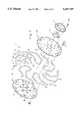
- FIG. 1is a fragmentary right, front perspective view of a planting machine incorporating a residue wheel attachment in accordance with the principles of the present invention
- FIG. 2is an enlarged right front isometric view of the residue wheel attachment itself and an associated coulter;
- FIG. 3is a top plan view of the residue wheel and associated coulter of FIG. 2,
- FIG. 4is an exploded illustration the wheel
- FIG. 5is an enlarged, side elevational view of the wheel.
- FIG. 6is a plan view of one of the tine units of the wheel.
- the planting machine 10 in FIG. 1has a frame 12 supported by one or more ground wheels 14.
- An opener 16is carried by the frame 12 for making a seed trench or slot in the ground and depositing successive seeds into the trench at regular intervals as the machine is advanced.
- a fluted coulter 18may be provided ahead of the opener to assist in forming the seed trench.
- a residue wheel attachment 20is secured to the frame 12 ahead of the opener 16 and the coulter 18 for clearing a path through crop residue and debris that would otherwise impede access of the opener 16 and coulter 18 to the ground surface.
- An additional coulter 22(FIGS. 2 and 3) may be made a part of the residue wheel attachment 20, if desired, to facilitate the application and incorporation of starter fertilizer in a subsurface band at the time of planting.
- the attachment 20includes an upright swivel shaft 24 secured to the frame 12 by a mounting clamp 26.
- a downwardly extending bracket 28is secured to the lower end of shaft 24 and can be pivoted around the shaft 24 into any one of a number of adjusted positions by loosening and then retightening a set screw 30.
- a generally rectangular extension plate 32is bolted to the lower end of bracket 28 and projects rearwardly therefrom to support a mounting plate 34 that is provided with an outwardly projecting, tubular boss 36 which is only barely visible in FIGS. 2 and 3.
- a spring tension adjust plate 38slips onto the boss 36 and butts up against the mounting plate 34 where it may be held in any one of several selectible rotative positions by a retaining bolt 40 inserted into an appropriate hole (not shown) in the mounting plate 34 and one of the three holes 42 (only two being visible) in the spring adjust plate 38.
- the spring adjust plate 38has an outturned ear 44 which serves as a spring stop for the torsion spring of the assembly as will hereinafter be explained.
- the attachment 20further includes a support arm weldment 46 that includes a slightly crooked arm 48 having a transverse stub shaft (not shown) at its upper end that is rotatably received within the boss 36 so that arm 48 can swing up and down about the horizontal axis of the boss 36.
- the stub shaftis retained within the boss 36 by a suitable clip or other means well within the skill of those in the art.
- a torsion spring 50encircles the boss 36 and bears against the ear 44 at one end while being hooked onto the arm 48 at the opposite end whereby to yieldably bias the arm 48 toward the ground.
- Interior stop means(not shown) associated with the boss 36 and the stub shaft of support arm weldment 46 cooperate to limit the extent of up and down swinging of the arm 48.
- the wheel attachment 20further includes a wheel 52 rotatably secured to the outer end of the arm 48 for free-wheeling rotation relative thereto.
- the wheel 52has a bearing assembly 54 (FIG. 4) pressed into a flange plate 56 that is in turn secured to the wheel 52 by bolts 58.
- a boltenters the bearing assembly 54 from the back side of the wheel 52 and is threaded into a nut 60 fixed to the lower end of the arm 48 to secure the wheel 52 to arm 48.
- the wheel 52has as its primary components a circular hub 62 and a plurality of spring tines 64 projecting from the hub 62 around its outer periphery.
- the tines 64are equally spaced around the hub 62 but preferably comprise individual legs of a series of generally U-shaped, double fine units 66 that are fastened to the hub 62 at their point of interconnection with one another. All of the tines 64 lie within the same flat plane as the hub 62.
- each of the double tine units 66has a generally U-shaped overall configuration and is preferably constructed from spring steel rod of circular cross-sectional configuration that has been cut to length and formed into the desired shape.
- the two tines 64 of each unit 66comprise two laterally spaced apart legs 64a and 64b that are integrally joined together at their inner ends by a bight 68.
- the bight 68also serves as the mounting portion of each unit 66 as will be seen.
- the two legs 64a and 64bdiverge from one another in a symmetrical manner as the bight 68 is departed.
- the two legseach turn forwardly at a bend 70 and continue conjointly outwardly in slanted, but straight, shank portions 72.
- the shank portions 72are angled forwardly from their respective bight arms 68 at the same angle, i.e., approximately 135 degrees, but do not extend in parallelism with one another because of the diverging nature of the bight arms.
- the two legsAt approximately two-thirds of the way out, the two legs each have another bend 74 and turn further forwardly in straight, sweeping foot portions 76 that extend at approximately 135 degree angles to their respective shank portions 72.
- the legs 64a and 64bare provided with short downturned driving prongs 78 that are disposed to project substantially radially from the central axis of the wheel when the tine unit is installed. All portions of the tine unit 66 lie in the same plane.
- the hub 62is comprised of a pair of circular, stamped metal plates 80 and 82 of virtually identical construction that are inverted relative to one another and are held together in superimposed relationship by a series of carriage bolts 84.
- Each of the plates 80,82is substantially flat except for a series of arcuate depressions 86 about their peripheries that are configured to complementally receive the bights 68 of the tine units 66 when they are installed on the hub 62.
- All of the tine units 66are installed in the same orientation with the leg 64a leading the leg 64b with respect to the intended direction of rotation of the wheel.
- the tine leg 64aengages the ground first, as between the two legs 64a and 64b.
- the foot portions 76are disposed to lie flatly against the ground and project opposite to the direction of rotation of the wheel as they successively move into engagement with the ground. While the prongs 78 penetrate the soil slightly to obtain traction for the wheel, they are limited in their depth of penetration by the foot portions 76 against the top surface of the soil.
- the support arm 48extends generally downwardly and outwardly such that the wheel 52 rotates about an axis that is oblique with respect to the path of travel of the opener 16.
- the wheel 52is tipped slightly forwardly at its upper end as shown in the plan view of FIG. 3 such that the axis of rotation of the wheel 52 extends forwardly, outwardly and slightly downwardly.
- the wheel 52is usually pulled rather than pushed by the support arm 48, although with certain minor mounting modifications the wheel 52 can be mounted ahead of the hub 88 of the fertilizer coulter 18 rather than behind the hub as in the illustrated embodiment.
- the wheel 52can be set up for either left or right-hand throw.
- the wheel 52As the machine 10 moves forwardly in the direction of the arrow 90 in FIGS. 1,2,3 and 5, the wheel 52 is disposed in forward alignment with the opener 16. Consequently, as the tines 64 of the obliquely angled wheel 52 engage the ground and the residue lying thereon, the forward motion of the machine 10 causes the free-wheeling wheel to be rotatively driven by the ground in a clockwise direction viewing FIGS. 1, 2 and 5 as illustrated by the arrow 92 in those figures. Consequently, debris and residue are swept cleanly from the ground surface by the tines 64, particularly foot portions 76, as the tines move downwardly, rearwardly and outwardly and then upwardly, rearwardly and outwardly through the trash.
- the foot portions 76are especially helpful as they come down flatly against the residue and then sweep it to one side as they move generally horizontally outwardly and rearwardly through the critical zone.
- the tines 64In the event stones or other hard foreign objects are encountered by the tines 64, they simply flex yieldably to the extent necessary to avoid breakage. However, if for any reason a tine does become damaged or broken, it may be easily removed and replaced by loosening the bolts 84 to separate the plates 80, 82. If uneven terrain is encountered, the torsion spring 50 permits the arm 48 to swing up independently of the opener 16 to the extent necessary to accomodate the terrain change.
Landscapes
- Life Sciences & Earth Sciences (AREA)
- Soil Sciences (AREA)
- Environmental Sciences (AREA)
- Engineering & Computer Science (AREA)
- Mechanical Engineering (AREA)
- Transplanting Machines (AREA)
Abstract
Description
This invention relates to the field of planting or drilling and, more particularly, to an attachment for such equipment for clearing away residue from in front of the planter to provide a relatively clean soil surface into which the planter can open a trench and deposit the seed.
Residue wheels have become increasingly popular in recent years as a means of removing a sufficient amount of crop residue from the soft surface to enable the planting or drilling unit to have a clean surface to work with. However, most conventional attachments require two of such wheels per crop row in order to perform effectively. Moreover, few of them make adequate provision for removing and replacing broken or damaged tines. In addition, many such attachments make no provision for maintaining a constant relationship between the tines and the soil. Specifically, even with floating mechanisms, many conventional tines have a tendency to gouge the soil and create a trench due to their design and shape.
Accordingly, one important object of the present invention is to provide an improved residue wheel which is so highly effective at sweeping crop residue from the seed planting zone that only a single one of such wheels is needed per row. In addition, an important object of the invention is the provision of tines which can be relatively easily removed and replaced in the event they become damaged or broken. Further objects include providing tines which are damage-resistant due to their yieldable nature yet are still highly effective in terms of their ability to move trash; providing a wheel that can be manufactured efficiently through the use of stamped and formed metal parts; providing a wheel which will instantly adjust to and accomodate changing terrain; providing a wheel that discourages wrapping of residue; and providing a wheel in which the special shape of the tine itself serves to control the depth of penetration of the tine into the soil.
In carrying out the foregoing and other important objects, the present invention contemplates a residue wheel having tines which are constructed from resilient spring steel so that the tines are resistant to breakage when hard foreign objects such as stones and roots are encountered. Each tine comprises one fine of a double tine unit having a generally U-shaped, integral body in which the two legs of the body comprise the two tines of the unit. A bight that joins the legs together at one end is clamped between a pair of superimposed plates forming the hub of the wheel so as to secure the tine unit to the hub, while the remaining portions of each tine project outwardly beyond the hub for engagement with the trash and the ground. The outer end of each tine is bent outwardly to project in a direction opposite to the direction of rotation of the wheel so that as the wheel rotates, the tines successively come into generally flat sweeping engagement with the ground. Downturned driving prongs are provided at the outer ends of the tines for assuring positive traction between the wheel and the ground.
FIG. 1 is a fragmentary right, front perspective view of a planting machine incorporating a residue wheel attachment in accordance with the principles of the present invention;
FIG. 2 is an enlarged right front isometric view of the residue wheel attachment itself and an associated coulter;
FIG. 3 is a top plan view of the residue wheel and associated coulter of FIG. 2,
FIG. 4 is an exploded illustration the wheel;
FIG. 5 is an enlarged, side elevational view of the wheel; and
FIG. 6 is a plan view of one of the tine units of the wheel.
Theplanting machine 10 in FIG. 1 has aframe 12 supported by one ormore ground wheels 14. Anopener 16 is carried by theframe 12 for making a seed trench or slot in the ground and depositing successive seeds into the trench at regular intervals as the machine is advanced. Afluted coulter 18 may be provided ahead of the opener to assist in forming the seed trench.
In accordance with the principles of the present invention, aresidue wheel attachment 20 is secured to theframe 12 ahead of theopener 16 and thecoulter 18 for clearing a path through crop residue and debris that would otherwise impede access of theopener 16 and coulter 18 to the ground surface. An additional coulter 22 (FIGS. 2 and 3) may be made a part of theresidue wheel attachment 20, if desired, to facilitate the application and incorporation of starter fertilizer in a subsurface band at the time of planting.
Theattachment 20 includes an uprightswivel shaft 24 secured to theframe 12 by amounting clamp 26. A downwardly extendingbracket 28 is secured to the lower end ofshaft 24 and can be pivoted around theshaft 24 into any one of a number of adjusted positions by loosening and then retightening aset screw 30. A generallyrectangular extension plate 32 is bolted to the lower end ofbracket 28 and projects rearwardly therefrom to support amounting plate 34 that is provided with an outwardly projecting,tubular boss 36 which is only barely visible in FIGS. 2 and 3. A spring tension adjustplate 38 slips onto theboss 36 and butts up against themounting plate 34 where it may be held in any one of several selectible rotative positions by a retaining bolt 40 inserted into an appropriate hole (not shown) in themounting plate 34 and one of the three holes 42 (only two being visible) in the spring adjustplate 38. The springadjust plate 38 has an outturned ear 44 which serves as a spring stop for the torsion spring of the assembly as will hereinafter be explained.
Theattachment 20 further includes asupport arm weldment 46 that includes a slightlycrooked arm 48 having a transverse stub shaft (not shown) at its upper end that is rotatably received within theboss 36 so thatarm 48 can swing up and down about the horizontal axis of theboss 36. The stub shaft is retained within theboss 36 by a suitable clip or other means well within the skill of those in the art. Atorsion spring 50 encircles theboss 36 and bears against the ear 44 at one end while being hooked onto thearm 48 at the opposite end whereby to yieldably bias thearm 48 toward the ground. Interior stop means (not shown) associated with theboss 36 and the stub shaft ofsupport arm weldment 46 cooperate to limit the extent of up and down swinging of thearm 48.
Thewheel attachment 20 further includes awheel 52 rotatably secured to the outer end of thearm 48 for free-wheeling rotation relative thereto. Thewheel 52 has a bearing assembly 54 (FIG. 4) pressed into aflange plate 56 that is in turn secured to thewheel 52 bybolts 58. A bolt (not shown) enters thebearing assembly 54 from the back side of thewheel 52 and is threaded into a nut 60 fixed to the lower end of thearm 48 to secure thewheel 52 toarm 48.
Thewheel 52 has as its primary components acircular hub 62 and a plurality ofspring tines 64 projecting from thehub 62 around its outer periphery. Thetines 64 are equally spaced around thehub 62 but preferably comprise individual legs of a series of generally U-shaped, doublefine units 66 that are fastened to thehub 62 at their point of interconnection with one another. All of thetines 64 lie within the same flat plane as thehub 62.
As illustrated in FIG. 6 each of thedouble tine units 66 has a generally U-shaped overall configuration and is preferably constructed from spring steel rod of circular cross-sectional configuration that has been cut to length and formed into the desired shape. The twotines 64 of eachunit 66 comprise two laterally spaced apartlegs bight 68. Thebight 68 also serves as the mounting portion of eachunit 66 as will be seen.
The twolegs bight 68 is departed. At approximately one-third of the way out, the two legs each turn forwardly at abend 70 and continue conjointly outwardly in slanted, but straight,shank portions 72. Theshank portions 72 are angled forwardly from their respectivebight arms 68 at the same angle, i.e., approximately 135 degrees, but do not extend in parallelism with one another because of the diverging nature of the bight arms. At approximately two-thirds of the way out, the two legs each have anotherbend 74 and turn further forwardly in straight,sweeping foot portions 76 that extend at approximately 135 degree angles to their respectiveshank portions 72. At the outermost ends of thefoot portions 76 thelegs downturned driving prongs 78 that are disposed to project substantially radially from the central axis of the wheel when the tine unit is installed. All portions of thetine unit 66 lie in the same plane.
Thehub 62 is comprised of a pair of circular, stampedmetal plates carriage bolts 84. Each of theplates arcuate depressions 86 about their peripheries that are configured to complementally receive thebights 68 of thetine units 66 when they are installed on thehub 62. There is onebolt 84 for eachtine unit 66, with the bolt being centered below the arch of the bight when the tine unit is installed, thus assuring a tight clamping action of theplates bights 68 in the area of thedepressions 86.
All of thetine units 66 are installed in the same orientation with theleg 64a leading theleg 64b with respect to the intended direction of rotation of the wheel. Thus, as illustrated in FIG. 5, thetine leg 64a engages the ground first, as between the twolegs foot portions 76 are disposed to lie flatly against the ground and project opposite to the direction of rotation of the wheel as they successively move into engagement with the ground. While theprongs 78 penetrate the soil slightly to obtain traction for the wheel, they are limited in their depth of penetration by thefoot portions 76 against the top surface of the soil.
It will be seen that thesupport arm 48 extends generally downwardly and outwardly such that thewheel 52 rotates about an axis that is oblique with respect to the path of travel of theopener 16. Preferably, thewheel 52 is tipped slightly forwardly at its upper end as shown in the plan view of FIG. 3 such that the axis of rotation of thewheel 52 extends forwardly, outwardly and slightly downwardly. Preferably, thewheel 52 is usually pulled rather than pushed by thesupport arm 48, although with certain minor mounting modifications thewheel 52 can be mounted ahead of thehub 88 of thefertilizer coulter 18 rather than behind the hub as in the illustrated embodiment. Furthermore, thewheel 52 can be set up for either left or right-hand throw.
As themachine 10 moves forwardly in the direction of thearrow 90 in FIGS. 1,2,3 and 5, thewheel 52 is disposed in forward alignment with theopener 16. Consequently, as thetines 64 of the obliquely angledwheel 52 engage the ground and the residue lying thereon, the forward motion of themachine 10 causes the free-wheeling wheel to be rotatively driven by the ground in a clockwise direction viewing FIGS. 1, 2 and 5 as illustrated by thearrow 92 in those figures. Consequently, debris and residue are swept cleanly from the ground surface by thetines 64, particularlyfoot portions 76, as the tines move downwardly, rearwardly and outwardly and then upwardly, rearwardly and outwardly through the trash. Thefoot portions 76 are especially helpful as they come down flatly against the residue and then sweep it to one side as they move generally horizontally outwardly and rearwardly through the critical zone.
In the event stones or other hard foreign objects are encountered by thetines 64, they simply flex yieldably to the extent necessary to avoid breakage. However, if for any reason a tine does become damaged or broken, it may be easily removed and replaced by loosening thebolts 84 to separate theplates torsion spring 50 permits thearm 48 to swing up independently of theopener 16 to the extent necessary to accomodate the terrain change.
Although preferred forms of the invention have been described above, it is to be recognized that such disclosure is by way of illustration only, and should not be utilized in a limiting sense in interpreting the scope of the present invention. Obvious modifications to the exemplary embodiments, as hereinabove set forth, could be readily made by those skilled in the art without departing from the spirit of the present invention.
The inventors hereby state their intent to rely on the Doctrine of Equivalents to determine and assess the reasonably fair scope of their invention as pertains to any apparatus not materially departing from but outside the literal scope of the invention as set out in the following claims.
Claims (26)
1. In a seed planting machine having a ground-driven residue wheel for clearing residue from the intended path of travel of an opener of the machine, the improvement in said residue wheel comprising:
a hub rotatable about an axis extending obliquely of said path of travel; and
a plurality of elongated spring tines projecting from the hub in disposition for engaging and raking residue from said path of travel as the machine is advanced,
each of said tines including as an integral part thereof an outer elongated foot portion projecting generally opposite to the direction of rotation of the wheel and disposed to lie generally flatly against the top surface of the ground as the tines are successively brought into engagement with the ground during forward movement of the machine for sweeping the residue to one side of the path of travel,
each of said foot portions having a downturned driving prong at an outer end thereof so that the prong projects down into the ground when the foot portion of its tine is disposed generally flatly against the top surface of the ground,
said foot portions serving to limit the depth of penetration of the driving prongs and to resist the accumulation of residue on the wheel.
2. In a planting machine as claimed in claim 1, each of said tines having all portions thereof disposed in a same plane.
3. In a planting machine as claimed in claim 1,
each of said tines further having an inner shank portion integrally joined to an inner end of said foot portion for spacing the foot portion outwardly away from the hub.
4. In a planting machine as claimed in claim 3,
each of said tines additionally having a mounting portion integrally joined to an inner end of said shank portion for securing the tine to the hub.
5. In a plating machine as claimed in claim 1,
said tines being connected together in pairs, with the tines of each pair comprising individual legs of a single, generally U-shaped unit having a bight that interconnects the two legs at an inner end of the legs.
6. In a planting machine as claimed in claim 5,
each tine unit having an inner mounting portion adjacent the bight wherein the legs of the unit diverge oppositely from one another as the bight is departed, an intermediate shank portion wherein the legs both slant outwardly in a direction generally opposite to the direction of rotation of the wheel, and an outer sweeping portion presented by the foot portions of the tines.
7. In a planting machine as claimed in claim 6,
each of said tines having all portions thereof disposed in a same plane.
8. In a planting machine as claimed in claim 5,
said hub comprising a pair of generally flat, superimposed plates having the bights of the tine units sandwiched therebetween, and releasable fasteners removably retaining said plates in said superimposed relationship to permit removal and replacement of the tine units.
9. In a planting machine as claimed in claim 8,
said plates having depressions configured to matingly receive opposite faces of the bights of the tine units.
10. In a planting machine as claimed in claim 9,
there being one fastener for each tine unit with the fastener extending between the legs of each unit in the area of said bight.
11. In a planting machine as claimed in claim 1; and
mechanism coupled with said hub for yieldably biasing the hub toward the ground.
12. A residue wheel for use in clearing residue from an intended path of travel of a seed planting machine comprising:
a hub adapted for rotation about an axis extending obliquely of said path of travel; and
a plurality of elongated spring tines projecting from the hub in disposition for engaging and raking residue from said path of travel as the machine is advanced,
each of said tines including as an integral part thereof an outer elongated foot portion projecting generally opposite to the direction of rotation of the wheel and disposed to lie generally flatly against the top surface of the ground as the tines are successively brought into engagement with the ground during forward movement of the machine for sweeping the residue to one side of the path of travel,
each of said foot portions having a downturned driving prong at an outer end thereof so that the prong projects down into the ground when the foot portion of its tine is disposed generally flatly against the top surface of the ground,
said foot portions serving to limit the depth of penetration of the driving prongs and to resist the accumulation of residue on the wheel.
13. A residue wheel as claimed in claim 12,
each of said tines having all portions thereof disposed in a same plane.
14. A residue wheel as claimed in claim 12,
each of said tines further having an inner shank portion integrally joined to an inner end of said foot portion for spacing the foot portion outwardly away from the hub.
15. A residue wheel as claimed in claim 14,
each of said tines additionally having a mounting portion integrally joined to an inner end of said shank portion for securing the tine to the hub.
16. A residue wheel as claimed in claim 12,
said tines being connected together in pairs, with the tines of each pair comprising individual legs of a single, generally U-shaped unit having a bight that interconnects the two legs at an inner end of the legs.
17. A residue wheel as claimed in claim 16,
each tine unit having an inner mounting portion adjacent the bight wherein the legs of the unit diverge oppositely from one another as the bight is departed, an intermediate shank portion wherein the legs both slant outwardly in a direction generally opposite to the direction of rotation of the wheel, and an outer sweeping portion presented by the foot portions of the tines.
18. A residue wheel as claimed in claim 17,
each of said tines having all portions thereof disposed in a same plane.
19. A residue wheel as claimed in claim 16,
said hub comprising a pair of generally flat, superimposed plates having the bights of the tine units sandwiched therebetween, and releasable fasteners removably retaining said plates in said superimposed relationship to permit removal and replacement of the tine units.
20. A residue wheel as claimed in claim 19,
said plates having depressions configured to matingly receive opposite faces of the bights of the tine units.
21. A residue wheel as claimed in claim 20,
there being one fastener for each tine unit with the fastener extending between the legs of each unit in the area of said bight.
22. A replaceable tine unit for a residue wheel comprising a generally U-shaped, unitary body having a pair of elongated, resilient, laterally spaced apart legs integrally interconnected at one end by a bight, one of said legs comprising a leading leg with respect to the intended direction of rotation of the wheel when the tine unit is installed thereon and the wheel is placed in use and the other of said legs comprising a trailing leg with respect to said intended direction of rotation, each of said legs having an outer sweeping foot portion inturned generally toward said bight and disposed at least generally within the plane of the bight and projecting generally in a direction opposite to said intended direction of rotation, each of said legs having a driving prong outturned generally away from the bight and located at an outer end of the foot portion.
23. A replaceable tine unit as claimed in claim 22,
said body having all portions thereof disposed in the same plane.
24. A replaceable tine unit as claimed in claim 22,
each of said legs further having an intermediate shank portion connecting the foot portion with the bight.
25. A replaceable tine unit as claimed in claim 24,
said legs diverging symmetrically outwardly from one another at said bight and slanting conjointly outwardly from the bight in a direction opposite to said direction of rotation at said intermediate shank portion.
26. A replaceable tine unit as claimed in claim 22,
said tine unit being constructed from formed metal rod of circular cross-sectional configuration.
Priority Applications (2)
| Application Number | Priority Date | Filing Date | Title |
|---|---|---|---|
| US08/503,382US5657707A (en) | 1995-07-17 | 1995-07-17 | Spring-tine residue wheel for planters |
| CA002181132ACA2181132C (en) | 1995-07-17 | 1996-07-12 | Spring-tine residue wheel for planters |
Applications Claiming Priority (1)
| Application Number | Priority Date | Filing Date | Title |
|---|---|---|---|
| US08/503,382US5657707A (en) | 1995-07-17 | 1995-07-17 | Spring-tine residue wheel for planters |
Publications (1)
| Publication Number | Publication Date |
|---|---|
| US5657707Atrue US5657707A (en) | 1997-08-19 |
Family
ID=24001858
Family Applications (1)
| Application Number | Title | Priority Date | Filing Date |
|---|---|---|---|
| US08/503,382Expired - LifetimeUS5657707A (en) | 1995-07-17 | 1995-07-17 | Spring-tine residue wheel for planters |
Country Status (2)
| Country | Link |
|---|---|
| US (1) | US5657707A (en) |
| CA (1) | CA2181132C (en) |
Cited By (63)
| Publication number | Priority date | Publication date | Assignee | Title |
|---|---|---|---|---|
| US5794713A (en)* | 1996-08-15 | 1998-08-18 | Ron Lefevre | Universal hub assembly |
| US5878678A (en)* | 1997-07-30 | 1999-03-09 | Deere & Company | Trash cleaning structure for a furrow opening device |
| US6102132A (en)* | 1997-08-18 | 2000-08-15 | Schimke; Harvey W. | Farm land coulter assembly |
| US6223663B1 (en) | 1997-07-30 | 2001-05-01 | Deere & Company | Trash cleaning structure for a furrow opening device |
| US6253692B1 (en) | 1999-02-24 | 2001-07-03 | Deere & Company | Row cleaner suspension |
| US6279666B1 (en)* | 1996-02-09 | 2001-08-28 | A.I.L., Inc. | Row crop debris clearing apparatus |
| US6345671B1 (en) | 2000-06-15 | 2002-02-12 | The United States Of America As Represented By The Secretary Of Agriculture | Flexible ground-driven residue management wheel |
| US6382114B1 (en)* | 1999-12-15 | 2002-05-07 | Paul Lanpher | Conservation farming strip till nitrogen applicator |
| US20040094079A1 (en)* | 1993-06-08 | 2004-05-20 | Bassett James H. | Apparatus for preparing soil for the placement of seed and additive |
| US20050263050A1 (en)* | 2004-05-12 | 2005-12-01 | Bassett James H | Agricultural tillage device |
| US20090025944A1 (en)* | 2007-07-24 | 2009-01-29 | Dawn Equipment Company | Agricultural Tillage Device |
| WO2009127066A1 (en)* | 2008-04-18 | 2009-10-22 | Straw Track Manufacturing Inc. | Residue clearing for agricultural implements |
| US20090321096A1 (en)* | 2008-06-27 | 2009-12-31 | Winick Alan E | Finger wheel row cleaner |
| USD621421S1 (en) | 2007-09-27 | 2010-08-10 | Falk Henry J | Spading vertical-tillage tool comprised of multiple disk blades |
| CN102480911A (en)* | 2009-04-15 | 2012-05-30 | 彼得·狄龙 | Reduces crop residue buildup on plow posts |
| US8327780B2 (en) | 2009-10-16 | 2012-12-11 | Dawn Equipment Company | Agricultural implement having fluid delivery features |
| US8359988B2 (en) | 2007-07-24 | 2013-01-29 | Dawn Equipment Company | Agricultural tillage device |
| US8393407B2 (en) | 2010-04-12 | 2013-03-12 | Brian E. Freed | Crop residue clearing device |
| US8544397B2 (en) | 2010-09-15 | 2013-10-01 | Dawn Equipment Company | Row unit for agricultural implement |
| US8544398B2 (en) | 2010-09-15 | 2013-10-01 | Dawn Equipment Company | Hydraulic down pressure control system for closing wheels of an agricultural implement |
| US8636077B2 (en) | 2012-05-22 | 2014-01-28 | Dawn Equipment Company | Agricultural tool with structural housing for hydraulic actuator |
| US8763713B2 (en) | 2012-01-27 | 2014-07-01 | Dawn Equipment Company | Agricultural implement with automatic down pressure control |
| US8776702B2 (en) | 2010-09-15 | 2014-07-15 | Dawn Equipment Company | Hydraulic down pressure control system for an agricultural implement |
| USRE45091E1 (en) | 2008-12-01 | 2014-08-26 | Dawn Equipment Company | Row-clearing unit for agricultural implement |
| US8863857B2 (en) | 2011-02-23 | 2014-10-21 | Dawn Equipment Company | Row unit for agricultural implement |
| US8875640B1 (en) | 2010-12-15 | 2014-11-04 | Vti, L.L.C. | Slurry applicator for an agricultural machine |
| US8910581B2 (en) | 2012-07-25 | 2014-12-16 | Dawn Equipment Company | Side dressing fertilizer coulter |
| US8985232B2 (en) | 2012-08-20 | 2015-03-24 | Dawn Equipment Company | Agricultural apparatus for sensing and providing feedback of soil property changes in real time |
| US9055712B2 (en) | 2010-09-15 | 2015-06-16 | Dawn Equipment Company | Agricultural apparatus with integrated controller for a row unit |
| US9107337B2 (en) | 2012-08-20 | 2015-08-18 | Dawn Equipment Company | Agricultural apparatus for sensing and providing feedback of soil property changes in real time |
| US9107338B2 (en) | 2010-09-15 | 2015-08-18 | Dawn Equipment Company | Agricultural systems |
| US9144189B2 (en) | 2012-07-25 | 2015-09-29 | Precision Planting Llc | Integrated implement downforce control systems, methods, and apparatus |
| US9192091B2 (en) | 2013-02-01 | 2015-11-24 | Dawn Equipment Company | Agricultural apparatus with hybrid single-disk, double-disk coulter arrangement |
| US9215839B2 (en) | 2013-02-01 | 2015-12-22 | Dawn Equipment Company | Agricultural apparatus with hybrid single-disk, double-disk coulter arrangement |
| US9226440B2 (en) | 2010-09-15 | 2016-01-05 | Dawn Equipment Company | Agricultural apparatus with hydraulic cylinder and manifold for a row unit |
| US9232687B2 (en) | 2010-09-15 | 2016-01-12 | Dawn Equipment Company | Agricultural systems |
| US9241438B2 (en) | 2014-02-05 | 2016-01-26 | Dawn Equipment Company | Agricultural system for field preparation |
| US9271437B2 (en) | 2011-07-01 | 2016-03-01 | Charles H. Martin | Agricultural field preparation device |
| US9288937B2 (en) | 2011-08-05 | 2016-03-22 | Precision Planting Llc | Apparatus, systems and methods for row unit downforce control |
| WO2017031590A1 (en) | 2015-08-26 | 2017-03-02 | One Pass Implements Inc. | Residue management tool for seeders |
| US9615497B2 (en) | 2014-02-21 | 2017-04-11 | Dawn Equipment Company | Modular autonomous farm vehicle |
| EP3152991A1 (en) | 2015-10-08 | 2017-04-12 | Badalini Srl | Apparatus for removing weeds, and associated agricultural machine |
| US9668398B2 (en) | 2014-02-05 | 2017-06-06 | Dawn Equipment Company | Agricultural system for field preparation |
| US9723778B2 (en) | 2014-11-07 | 2017-08-08 | Dawn Equipment Company | Agricultural system |
| US9848522B2 (en) | 2014-11-07 | 2017-12-26 | Dawn Equipment Company | Agricultural system |
| RU2643823C1 (en)* | 2016-09-27 | 2018-02-06 | Федеральное государственное бюджетное образовательное учреждение высшего образования "Донской государственный аграрный университет" (ФГБОУ ВО Донской ГАУ) | Rotational working element of tillage tool |
| US10444774B2 (en) | 2014-11-07 | 2019-10-15 | Dawn Equipment Company | Agricultural system |
| RU2704847C1 (en)* | 2018-12-19 | 2019-10-31 | Федеральное государственное бюджетное образовательное учреждение высшего образования "Донской государственный аграрный университет" (ФГБОУ ВО Донской ГАУ) | Rotary working element of the tiller |
| US20190343050A1 (en)* | 2018-05-11 | 2019-11-14 | Lynn Bishop | Hay Fluffer With Removable Tines |
| US10477760B2 (en) | 2015-12-28 | 2019-11-19 | Underground Agriculture, LLC | Agricultural organic device for weed control |
| US10548260B2 (en) | 2017-05-04 | 2020-02-04 | Dawn Equipment Company | System for automatically setting the set point of a planter automatic down pressure control system with a seed furrow sidewall compaction measurement device |
| US10582653B2 (en) | 2014-11-07 | 2020-03-10 | Dawn Equipment Company | Agricultural planting system with automatic depth control |
| US10645865B2 (en) | 2017-05-04 | 2020-05-12 | Dawn Equipment Company | Agricultural row unit with automatic control system for furrow closing device |
| US10721855B2 (en) | 2014-02-05 | 2020-07-28 | Dawn Equipment Company | Agricultural system for field preparation |
| CN111919549A (en)* | 2020-07-25 | 2020-11-13 | 石河子大学 | Pneumatic type slideway seed sowing device |
| US10980174B2 (en) | 2015-12-28 | 2021-04-20 | Underground Agriculture, LLC | Agricultural mowing device |
| US11006563B2 (en) | 2017-05-04 | 2021-05-18 | Dawn Equipment Company | Seed firming device for improving seed to soil contact in a planter furrow with feature designed to prevent the buildup of soil on the outer surfaces by discharging pressurized fluid |
| US11083134B2 (en) | 2015-12-28 | 2021-08-10 | Underground Agriculture, LLC | Agricultural inter-row mowing device |
| US11197411B2 (en) | 2014-11-07 | 2021-12-14 | Dawn Equipment Company | Agricultural planting system with automatic depth control |
| US11310956B1 (en) | 2021-06-01 | 2022-04-26 | Vti, L.L.C. | Slurry applicator with independent opening and closing units |
| US11350554B2 (en)* | 2018-09-13 | 2022-06-07 | Deere & Company | Agricultural planter including adjustable row cleaners |
| US12171152B2 (en) | 2010-09-15 | 2024-12-24 | Deere & Company | System and method for adaptively controlling depth of ground-engaging planting row unit using forward sensor that measures residue ahead of row unit |
| US12389816B2 (en) | 2013-02-04 | 2025-08-19 | Deere & Company | Agricultural systems |
Families Citing this family (1)
| Publication number | Priority date | Publication date | Assignee | Title |
|---|---|---|---|---|
| CN107128122B (en)* | 2017-05-19 | 2019-05-10 | 吉林大学 | A bionic sand walking wheel with multi-position casters |
Citations (43)
| Publication number | Priority date | Publication date | Assignee | Title |
|---|---|---|---|---|
| US720098A (en)* | 1901-12-21 | 1903-02-10 | Samuel Brassington Bamford | Hay-tedder. |
| US823240A (en)* | 1906-01-04 | 1906-06-12 | Emerson Mfg Co | Harrow-disk. |
| US1244982A (en)* | 1916-02-28 | 1917-10-30 | Ira C Horst | Rotary weeder. |
| US1680031A (en)* | 1927-08-04 | 1928-08-07 | Deere & Co | Trash cleaner |
| US2406500A (en)* | 1944-12-04 | 1946-08-27 | Gen Implement Corp | Hoe wheel plate stamping |
| US2419717A (en)* | 1944-03-29 | 1947-04-29 | Gen Implement Corp | Rotary hoe |
| US2438707A (en)* | 1944-04-13 | 1948-03-30 | Kropp Forge Company | Rotary tiller tooth and mounting |
| US2551313A (en)* | 1949-05-07 | 1951-05-01 | Climax Machinery Company | Rotary hoe wheel |
| US2851846A (en)* | 1952-09-26 | 1958-09-16 | Lely Nv C Van Der | Resilient rake wheel for side delivery rakes and the like |
| US2909888A (en)* | 1957-10-22 | 1959-10-27 | Lely Nv C Van Der | Raking wheels with tines |
| US2953891A (en)* | 1954-06-03 | 1960-09-27 | Lely Nv C Van Der | Rotary rake wheel |
| US3010526A (en)* | 1955-04-27 | 1961-11-28 | Lely Nv C Van Der | Wheel provided with tines or spokes |
| US3040819A (en)* | 1960-08-24 | 1962-06-26 | Int Harvester Co | Rotary hoe wheel |
| US3057145A (en)* | 1958-12-24 | 1962-10-09 | Lely Cornelis Van De | Rake wheels |
| US3065804A (en)* | 1961-03-22 | 1962-11-27 | Int Harvester Co | Rotary hoe wheel having interconnected teeth developing a trash guard ring |
| US3212585A (en)* | 1964-02-24 | 1965-10-19 | Arthur A Bezzerides | Soil mulcher |
| US3217813A (en)* | 1963-12-24 | 1965-11-16 | Koemel Walton Charles | Rotary weeder |
| US3306371A (en)* | 1965-06-14 | 1967-02-28 | Bush Roland Eugene | Rotary cultivators |
| US3393752A (en)* | 1965-05-07 | 1968-07-23 | Blackwelder Mfg Company | Rotary weeder |
| US3401753A (en)* | 1966-02-07 | 1968-09-17 | Paul A. Bezzerides | Earthworking tool for thinning plants |
| US3447295A (en)* | 1964-07-13 | 1969-06-03 | Texas Industries Inc | Rake wheels |
| US3452826A (en)* | 1965-03-02 | 1969-07-01 | Charles L Lehman | Cultivator |
| US3601201A (en)* | 1968-11-12 | 1971-08-24 | Vincent O Schmitz | Plow colter |
| US3770064A (en)* | 1969-06-06 | 1973-11-06 | Int Harvester Co | Row crop puller-shredder |
| US4055126A (en)* | 1975-05-16 | 1977-10-25 | Brown Ronald P | Sub-soil breaking, surface-soil conditioning and planter machine |
| US4114697A (en)* | 1977-04-18 | 1978-09-19 | Carlucci James J | Finger wheel |
| US4282934A (en)* | 1979-09-04 | 1981-08-11 | Bezzerides Paul A | Guidance system for agricultural implements |
| US4410048A (en)* | 1979-10-09 | 1983-10-18 | Tulen Jack A | Replacement spoons and fixtures for rotary hoe |
| US4502547A (en)* | 1980-04-28 | 1985-03-05 | National Research Development Corporation | Soil working device with cleaner |
| DE3435192A1 (en)* | 1984-09-25 | 1986-04-03 | Horsch Maschinen GmbH, 8380 Landau | Method and appliance for ground working |
| US4782654A (en)* | 1988-01-25 | 1988-11-08 | Bezzerides Paul A | Apparatus for removing material from a work area |
| US4785890A (en)* | 1986-09-10 | 1988-11-22 | Deere & Company | Ground-driven rotary row cleaner |
| US4947631A (en)* | 1988-02-24 | 1990-08-14 | Kuehn Melvin C | Bi-fold hay rake system |
| US4991660A (en)* | 1988-09-08 | 1991-02-12 | Agrikon Mezogazdasagi Gepgyarto Uzletag | Rolling hoe |
| US5065570A (en)* | 1988-02-24 | 1991-11-19 | Kuehn Melvin C | Bi-fold hay rake system |
| US5076180A (en)* | 1990-10-15 | 1991-12-31 | Yetter Manufacture Company | Trash clearing brush unit for a planter unit |
| US5129282A (en)* | 1991-07-24 | 1992-07-14 | Dawn Equipment Company | Mechanism for selectively repositioning a farm implement |
| US5255617A (en)* | 1992-02-14 | 1993-10-26 | Acra-Plant, Inc. | Ridge preparation tool for seed planting equipment |
| US5279236A (en)* | 1991-06-28 | 1994-01-18 | Truax James R | Seed planter |
| US5341754A (en)* | 1992-04-03 | 1994-08-30 | Farmer's Factory Co. | Rotary row cleaner for a planter |
| US5349911A (en)* | 1991-12-06 | 1994-09-27 | Unverferth Manufacturing Company, Inc. | Assembly used in farm implements to clear mulch for minimum tillage |
| US5419402A (en)* | 1993-06-07 | 1995-05-30 | Heintzman; Rick | Rotary hoe |
| US5443023A (en)* | 1993-03-15 | 1995-08-22 | Carroll; Walter R. | Seed furrow closing apparatus for agricultural planters |
- 1995
- 1995-07-17USUS08/503,382patent/US5657707A/ennot_activeExpired - Lifetime
- 1996
- 1996-07-12CACA002181132Apatent/CA2181132C/ennot_activeExpired - Fee Related
Patent Citations (43)
| Publication number | Priority date | Publication date | Assignee | Title |
|---|---|---|---|---|
| US720098A (en)* | 1901-12-21 | 1903-02-10 | Samuel Brassington Bamford | Hay-tedder. |
| US823240A (en)* | 1906-01-04 | 1906-06-12 | Emerson Mfg Co | Harrow-disk. |
| US1244982A (en)* | 1916-02-28 | 1917-10-30 | Ira C Horst | Rotary weeder. |
| US1680031A (en)* | 1927-08-04 | 1928-08-07 | Deere & Co | Trash cleaner |
| US2419717A (en)* | 1944-03-29 | 1947-04-29 | Gen Implement Corp | Rotary hoe |
| US2438707A (en)* | 1944-04-13 | 1948-03-30 | Kropp Forge Company | Rotary tiller tooth and mounting |
| US2406500A (en)* | 1944-12-04 | 1946-08-27 | Gen Implement Corp | Hoe wheel plate stamping |
| US2551313A (en)* | 1949-05-07 | 1951-05-01 | Climax Machinery Company | Rotary hoe wheel |
| US2851846A (en)* | 1952-09-26 | 1958-09-16 | Lely Nv C Van Der | Resilient rake wheel for side delivery rakes and the like |
| US2953891A (en)* | 1954-06-03 | 1960-09-27 | Lely Nv C Van Der | Rotary rake wheel |
| US3010526A (en)* | 1955-04-27 | 1961-11-28 | Lely Nv C Van Der | Wheel provided with tines or spokes |
| US2909888A (en)* | 1957-10-22 | 1959-10-27 | Lely Nv C Van Der | Raking wheels with tines |
| US3057145A (en)* | 1958-12-24 | 1962-10-09 | Lely Cornelis Van De | Rake wheels |
| US3040819A (en)* | 1960-08-24 | 1962-06-26 | Int Harvester Co | Rotary hoe wheel |
| US3065804A (en)* | 1961-03-22 | 1962-11-27 | Int Harvester Co | Rotary hoe wheel having interconnected teeth developing a trash guard ring |
| US3217813A (en)* | 1963-12-24 | 1965-11-16 | Koemel Walton Charles | Rotary weeder |
| US3212585A (en)* | 1964-02-24 | 1965-10-19 | Arthur A Bezzerides | Soil mulcher |
| US3447295A (en)* | 1964-07-13 | 1969-06-03 | Texas Industries Inc | Rake wheels |
| US3452826A (en)* | 1965-03-02 | 1969-07-01 | Charles L Lehman | Cultivator |
| US3393752A (en)* | 1965-05-07 | 1968-07-23 | Blackwelder Mfg Company | Rotary weeder |
| US3306371A (en)* | 1965-06-14 | 1967-02-28 | Bush Roland Eugene | Rotary cultivators |
| US3401753A (en)* | 1966-02-07 | 1968-09-17 | Paul A. Bezzerides | Earthworking tool for thinning plants |
| US3601201A (en)* | 1968-11-12 | 1971-08-24 | Vincent O Schmitz | Plow colter |
| US3770064A (en)* | 1969-06-06 | 1973-11-06 | Int Harvester Co | Row crop puller-shredder |
| US4055126A (en)* | 1975-05-16 | 1977-10-25 | Brown Ronald P | Sub-soil breaking, surface-soil conditioning and planter machine |
| US4114697A (en)* | 1977-04-18 | 1978-09-19 | Carlucci James J | Finger wheel |
| US4282934A (en)* | 1979-09-04 | 1981-08-11 | Bezzerides Paul A | Guidance system for agricultural implements |
| US4410048A (en)* | 1979-10-09 | 1983-10-18 | Tulen Jack A | Replacement spoons and fixtures for rotary hoe |
| US4502547A (en)* | 1980-04-28 | 1985-03-05 | National Research Development Corporation | Soil working device with cleaner |
| DE3435192A1 (en)* | 1984-09-25 | 1986-04-03 | Horsch Maschinen GmbH, 8380 Landau | Method and appliance for ground working |
| US4785890A (en)* | 1986-09-10 | 1988-11-22 | Deere & Company | Ground-driven rotary row cleaner |
| US4782654A (en)* | 1988-01-25 | 1988-11-08 | Bezzerides Paul A | Apparatus for removing material from a work area |
| US4947631A (en)* | 1988-02-24 | 1990-08-14 | Kuehn Melvin C | Bi-fold hay rake system |
| US5065570A (en)* | 1988-02-24 | 1991-11-19 | Kuehn Melvin C | Bi-fold hay rake system |
| US4991660A (en)* | 1988-09-08 | 1991-02-12 | Agrikon Mezogazdasagi Gepgyarto Uzletag | Rolling hoe |
| US5076180A (en)* | 1990-10-15 | 1991-12-31 | Yetter Manufacture Company | Trash clearing brush unit for a planter unit |
| US5279236A (en)* | 1991-06-28 | 1994-01-18 | Truax James R | Seed planter |
| US5129282A (en)* | 1991-07-24 | 1992-07-14 | Dawn Equipment Company | Mechanism for selectively repositioning a farm implement |
| US5349911A (en)* | 1991-12-06 | 1994-09-27 | Unverferth Manufacturing Company, Inc. | Assembly used in farm implements to clear mulch for minimum tillage |
| US5255617A (en)* | 1992-02-14 | 1993-10-26 | Acra-Plant, Inc. | Ridge preparation tool for seed planting equipment |
| US5341754A (en)* | 1992-04-03 | 1994-08-30 | Farmer's Factory Co. | Rotary row cleaner for a planter |
| US5443023A (en)* | 1993-03-15 | 1995-08-22 | Carroll; Walter R. | Seed furrow closing apparatus for agricultural planters |
| US5419402A (en)* | 1993-06-07 | 1995-05-30 | Heintzman; Rick | Rotary hoe |
Cited By (110)
| Publication number | Priority date | Publication date | Assignee | Title |
|---|---|---|---|---|
| US20040094079A1 (en)* | 1993-06-08 | 2004-05-20 | Bassett James H. | Apparatus for preparing soil for the placement of seed and additive |
| US7222575B2 (en) | 1993-06-08 | 2007-05-29 | Bassett James H | Apparatus for preparing soil for the placement of seed and additive |
| US20050217550A1 (en)* | 1993-06-08 | 2005-10-06 | Bassett James H | Apparatus for preparing soil for the placement of seed and additive |
| US6912963B2 (en)* | 1993-06-08 | 2005-07-05 | James H. Bassett | Apparatus for preparing soil for the placement of seed and additive |
| US6279666B1 (en)* | 1996-02-09 | 2001-08-28 | A.I.L., Inc. | Row crop debris clearing apparatus |
| US5794713A (en)* | 1996-08-15 | 1998-08-18 | Ron Lefevre | Universal hub assembly |
| US5878678A (en)* | 1997-07-30 | 1999-03-09 | Deere & Company | Trash cleaning structure for a furrow opening device |
| US5970892A (en)* | 1997-07-30 | 1999-10-26 | Deere & Company | Trash cleaning structure for a furrow opening device |
| US6223663B1 (en) | 1997-07-30 | 2001-05-01 | Deere & Company | Trash cleaning structure for a furrow opening device |
| US6102132A (en)* | 1997-08-18 | 2000-08-15 | Schimke; Harvey W. | Farm land coulter assembly |
| AU733357B2 (en)* | 1997-08-18 | 2001-05-10 | Harvey W Schimke | Farm land coulter assembly |
| US6253692B1 (en) | 1999-02-24 | 2001-07-03 | Deere & Company | Row cleaner suspension |
| AU763223B2 (en)* | 1999-02-24 | 2003-07-17 | Deere & Company | Row cleaner suspension |
| US6382114B1 (en)* | 1999-12-15 | 2002-05-07 | Paul Lanpher | Conservation farming strip till nitrogen applicator |
| US6345671B1 (en) | 2000-06-15 | 2002-02-12 | The United States Of America As Represented By The Secretary Of Agriculture | Flexible ground-driven residue management wheel |
| US7451712B2 (en) | 2004-05-12 | 2008-11-18 | Dawn Equipment Company | Agricultural tillage device |
| US7665539B2 (en) | 2004-05-12 | 2010-02-23 | Dawn Equipment Company | Agricultural tillage device |
| US20050263050A1 (en)* | 2004-05-12 | 2005-12-01 | Bassett James H | Agricultural tillage device |
| US20090025618A1 (en)* | 2004-05-12 | 2009-01-29 | Dawn Equipment Company | Agricultural tillage device |
| US8359988B2 (en) | 2007-07-24 | 2013-01-29 | Dawn Equipment Company | Agricultural tillage device |
| US20090025944A1 (en)* | 2007-07-24 | 2009-01-29 | Dawn Equipment Company | Agricultural Tillage Device |
| US7743718B2 (en) | 2007-07-24 | 2010-06-29 | Dawn Equipment Company | Agricultural tillage device |
| US20100300710A1 (en)* | 2007-07-24 | 2010-12-02 | Dawn Equipment Company | Agricultural tillage device |
| US8151717B2 (en) | 2007-07-24 | 2012-04-10 | Dawn Equipment Company | Agricultural tillage device |
| USD621421S1 (en) | 2007-09-27 | 2010-08-10 | Falk Henry J | Spading vertical-tillage tool comprised of multiple disk blades |
| WO2009127066A1 (en)* | 2008-04-18 | 2009-10-22 | Straw Track Manufacturing Inc. | Residue clearing for agricultural implements |
| US20090321096A1 (en)* | 2008-06-27 | 2009-12-31 | Winick Alan E | Finger wheel row cleaner |
| US8596375B2 (en) | 2008-06-27 | 2013-12-03 | Alan E. Winick | Finger wheel row cleaner |
| USRE45091E1 (en) | 2008-12-01 | 2014-08-26 | Dawn Equipment Company | Row-clearing unit for agricultural implement |
| CN102480911A (en)* | 2009-04-15 | 2012-05-30 | 彼得·狄龙 | Reduces crop residue buildup on plow posts |
| CN102480911B (en)* | 2009-04-15 | 2014-11-19 | 彼得·狄龙 | Reducing crop residue buildup on plow standard |
| US8327780B2 (en) | 2009-10-16 | 2012-12-11 | Dawn Equipment Company | Agricultural implement having fluid delivery features |
| US8393407B2 (en) | 2010-04-12 | 2013-03-12 | Brian E. Freed | Crop residue clearing device |
| US9232687B2 (en) | 2010-09-15 | 2016-01-12 | Dawn Equipment Company | Agricultural systems |
| US9167740B2 (en) | 2010-09-15 | 2015-10-27 | Dawn Equipment Company | Row unit for agricultural implement |
| US8770308B2 (en) | 2010-09-15 | 2014-07-08 | Dawn Equipment Company | Row unit for agricultural implement |
| US8776702B2 (en) | 2010-09-15 | 2014-07-15 | Dawn Equipment Company | Hydraulic down pressure control system for an agricultural implement |
| US10238024B2 (en) | 2010-09-15 | 2019-03-26 | Dawn Equipment Company | Row unit for agricultural implement |
| US9226440B2 (en) | 2010-09-15 | 2016-01-05 | Dawn Equipment Company | Agricultural apparatus with hydraulic cylinder and manifold for a row unit |
| US12150399B2 (en) | 2010-09-15 | 2024-11-26 | Deere & Company | Row unit for agricultural implement |
| US8544398B2 (en) | 2010-09-15 | 2013-10-01 | Dawn Equipment Company | Hydraulic down pressure control system for closing wheels of an agricultural implement |
| US10477752B2 (en) | 2010-09-15 | 2019-11-19 | Dawn Equipment Company | Row unit for agricultural implement |
| US10506755B2 (en) | 2010-09-15 | 2019-12-17 | Dawn Equipment Company | Agricultural systems |
| US9055712B2 (en) | 2010-09-15 | 2015-06-16 | Dawn Equipment Company | Agricultural apparatus with integrated controller for a row unit |
| US9788472B2 (en) | 2010-09-15 | 2017-10-17 | Dawn Equipment Company | Row unit for agricultural implement |
| US9107338B2 (en) | 2010-09-15 | 2015-08-18 | Dawn Equipment Company | Agricultural systems |
| US11470754B2 (en) | 2010-09-15 | 2022-10-18 | Dawn Equipment Company | Agricultural systems |
| US9144187B2 (en) | 2010-09-15 | 2015-09-29 | Dawn Equipment Company | Agricultural apparatus with hydraulic cylinder and manifold for a row unit |
| US11122726B2 (en) | 2010-09-15 | 2021-09-21 | Dawn Equipment Company | Agricultural systems |
| US8544397B2 (en) | 2010-09-15 | 2013-10-01 | Dawn Equipment Company | Row unit for agricultural implement |
| US12171152B2 (en) | 2010-09-15 | 2024-12-24 | Deere & Company | System and method for adaptively controlling depth of ground-engaging planting row unit using forward sensor that measures residue ahead of row unit |
| US9192089B2 (en) | 2010-09-15 | 2015-11-24 | Dawn Equipment Company | Row unit for agricultural implement |
| US9769980B1 (en) | 2010-12-15 | 2017-09-26 | Vti, L.L.C. | Slurry applicator for an agricultural machine |
| US8875640B1 (en) | 2010-12-15 | 2014-11-04 | Vti, L.L.C. | Slurry applicator for an agricultural machine |
| US8863857B2 (en) | 2011-02-23 | 2014-10-21 | Dawn Equipment Company | Row unit for agricultural implement |
| US11375653B2 (en) | 2011-07-01 | 2022-07-05 | Charles H. Martin | Agricultural field preparation device |
| US9271437B2 (en) | 2011-07-01 | 2016-03-01 | Charles H. Martin | Agricultural field preparation device |
| US9504198B2 (en) | 2011-07-01 | 2016-11-29 | Charles H. Martin | Crimping device for agricultural field preparation |
| US12058944B2 (en) | 2011-07-01 | 2024-08-13 | Charles H. Martin | Agricultural field preparation device |
| US10251324B2 (en) | 2011-07-01 | 2019-04-09 | Charles H. Martin | Agricultural field preparation device |
| US10806064B2 (en) | 2011-07-01 | 2020-10-20 | Charles H. Martin | Agricultural field preparation device |
| US10834863B2 (en) | 2011-08-05 | 2020-11-17 | Precision Planting Llc | Apparatus, systems and methods for row unit downforce control |
| US9288937B2 (en) | 2011-08-05 | 2016-03-22 | Precision Planting Llc | Apparatus, systems and methods for row unit downforce control |
| US8763713B2 (en) | 2012-01-27 | 2014-07-01 | Dawn Equipment Company | Agricultural implement with automatic down pressure control |
| US8636077B2 (en) | 2012-05-22 | 2014-01-28 | Dawn Equipment Company | Agricultural tool with structural housing for hydraulic actuator |
| US9144189B2 (en) | 2012-07-25 | 2015-09-29 | Precision Planting Llc | Integrated implement downforce control systems, methods, and apparatus |
| US9746007B2 (en) | 2012-07-25 | 2017-08-29 | Precision Planting Llc | Integrated implement downforce control systems, methods, and apparatus |
| US8910581B2 (en) | 2012-07-25 | 2014-12-16 | Dawn Equipment Company | Side dressing fertilizer coulter |
| US10443631B2 (en) | 2012-07-25 | 2019-10-15 | Precision Planting Llc | Integrated implement downforce control systems, methods, and apparatus |
| US9113589B2 (en) | 2012-08-20 | 2015-08-25 | Dawn Equipment Company | Agricultural apparatus for sensing and providing feedback of soil property changes in real time |
| US9107337B2 (en) | 2012-08-20 | 2015-08-18 | Dawn Equipment Company | Agricultural apparatus for sensing and providing feedback of soil property changes in real time |
| US8985232B2 (en) | 2012-08-20 | 2015-03-24 | Dawn Equipment Company | Agricultural apparatus for sensing and providing feedback of soil property changes in real time |
| US9215839B2 (en) | 2013-02-01 | 2015-12-22 | Dawn Equipment Company | Agricultural apparatus with hybrid single-disk, double-disk coulter arrangement |
| US9861022B2 (en) | 2013-02-01 | 2018-01-09 | Dawn Equipment Company | Agricultural apparatus with hybrid single-disk, double-disk coulter arrangement |
| US9192091B2 (en) | 2013-02-01 | 2015-11-24 | Dawn Equipment Company | Agricultural apparatus with hybrid single-disk, double-disk coulter arrangement |
| US9215838B2 (en) | 2013-02-01 | 2015-12-22 | Dawn Equipment Company | Agricultural apparatus with hybrid single-disk, double-disk coulter arrangement |
| US12389816B2 (en) | 2013-02-04 | 2025-08-19 | Deere & Company | Agricultural systems |
| US10433472B2 (en) | 2014-02-05 | 2019-10-08 | Dawn Equipment Company | Agricultural system for field preparation |
| US9241438B2 (en) | 2014-02-05 | 2016-01-26 | Dawn Equipment Company | Agricultural system for field preparation |
| US9668398B2 (en) | 2014-02-05 | 2017-06-06 | Dawn Equipment Company | Agricultural system for field preparation |
| US10721855B2 (en) | 2014-02-05 | 2020-07-28 | Dawn Equipment Company | Agricultural system for field preparation |
| US10485153B2 (en) | 2014-02-21 | 2019-11-26 | Dawn Equipment Company | Modular autonomous farm vehicle |
| US9615497B2 (en) | 2014-02-21 | 2017-04-11 | Dawn Equipment Company | Modular autonomous farm vehicle |
| US10251333B2 (en) | 2014-11-07 | 2019-04-09 | Dawn Equipment Company | Agricultural system |
| US9848522B2 (en) | 2014-11-07 | 2017-12-26 | Dawn Equipment Company | Agricultural system |
| US10444774B2 (en) | 2014-11-07 | 2019-10-15 | Dawn Equipment Company | Agricultural system |
| US10582653B2 (en) | 2014-11-07 | 2020-03-10 | Dawn Equipment Company | Agricultural planting system with automatic depth control |
| US9723778B2 (en) | 2014-11-07 | 2017-08-08 | Dawn Equipment Company | Agricultural system |
| US11197411B2 (en) | 2014-11-07 | 2021-12-14 | Dawn Equipment Company | Agricultural planting system with automatic depth control |
| EP3340762A4 (en)* | 2015-08-26 | 2019-05-01 | One Pass Implements Inc. | Residue management tool for seeders |
| WO2017031590A1 (en) | 2015-08-26 | 2017-03-02 | One Pass Implements Inc. | Residue management tool for seeders |
| EP3152991A1 (en) | 2015-10-08 | 2017-04-12 | Badalini Srl | Apparatus for removing weeds, and associated agricultural machine |
| EP3152991B1 (en)* | 2015-10-08 | 2019-12-04 | Badalini Srl | Apparatus for removing weeds, and associated agricultural machine |
| US10477760B2 (en) | 2015-12-28 | 2019-11-19 | Underground Agriculture, LLC | Agricultural organic device for weed control |
| US11083134B2 (en) | 2015-12-28 | 2021-08-10 | Underground Agriculture, LLC | Agricultural inter-row mowing device |
| US10980174B2 (en) | 2015-12-28 | 2021-04-20 | Underground Agriculture, LLC | Agricultural mowing device |
| RU2643823C1 (en)* | 2016-09-27 | 2018-02-06 | Федеральное государственное бюджетное образовательное учреждение высшего образования "Донской государственный аграрный университет" (ФГБОУ ВО Донской ГАУ) | Rotational working element of tillage tool |
| US12089518B2 (en) | 2017-05-04 | 2024-09-17 | Dawn Equipment Company, Inc. | Seed firming device for improving seed to soil contact in a planter furrow with feature designed to prevent the buildup of soil on the outer surfaces by discharging pressurized fluid |
| US10645865B2 (en) | 2017-05-04 | 2020-05-12 | Dawn Equipment Company | Agricultural row unit with automatic control system for furrow closing device |
| US10548260B2 (en) | 2017-05-04 | 2020-02-04 | Dawn Equipment Company | System for automatically setting the set point of a planter automatic down pressure control system with a seed furrow sidewall compaction measurement device |
| US11006563B2 (en) | 2017-05-04 | 2021-05-18 | Dawn Equipment Company | Seed firming device for improving seed to soil contact in a planter furrow with feature designed to prevent the buildup of soil on the outer surfaces by discharging pressurized fluid |
| US12290020B2 (en) | 2017-05-04 | 2025-05-06 | Deere & Company | System for automatically setting the set point of a planter automatic down pressure control system with a seed furrow sidewall compaction measurement device |
| US20190343050A1 (en)* | 2018-05-11 | 2019-11-14 | Lynn Bishop | Hay Fluffer With Removable Tines |
| US10986783B2 (en)* | 2018-05-11 | 2021-04-27 | Lynn Bishop | Hay fluffer with removable tines |
| US11350554B2 (en)* | 2018-09-13 | 2022-06-07 | Deere & Company | Agricultural planter including adjustable row cleaners |
| US12274199B2 (en) | 2018-09-13 | 2025-04-15 | Deere & Company | Agricultural planter including adjustable row cleaners |
| RU2704847C1 (en)* | 2018-12-19 | 2019-10-31 | Федеральное государственное бюджетное образовательное учреждение высшего образования "Донской государственный аграрный университет" (ФГБОУ ВО Донской ГАУ) | Rotary working element of the tiller |
| CN111919549A (en)* | 2020-07-25 | 2020-11-13 | 石河子大学 | Pneumatic type slideway seed sowing device |
| US11310956B1 (en) | 2021-06-01 | 2022-04-26 | Vti, L.L.C. | Slurry applicator with independent opening and closing units |
| US12016260B2 (en) | 2021-06-01 | 2024-06-25 | Vti, L.L.C. | Slurry applicator with independent opening and closing units |
Also Published As
| Publication number | Publication date |
|---|---|
| CA2181132C (en) | 1999-06-01 |
| CA2181132A1 (en) | 1997-01-18 |
Similar Documents
| Publication | Publication Date | Title |
|---|---|---|
| US5657707A (en) | Spring-tine residue wheel for planters | |
| US4760806A (en) | Conservation opener | |
| US5626196A (en) | Seed drill with scraper/soil firming attachment | |
| US7775293B2 (en) | Furrow closer | |
| US6325156B1 (en) | Gauge wheel and coulter arrangement for agricultural implement | |
| US4506610A (en) | Subsoil rotary cultivator | |
| US6223663B1 (en) | Trash cleaning structure for a furrow opening device | |
| US5497836A (en) | Row cleaner | |
| US8408324B2 (en) | Reducing build up of crop residue on shanks | |
| US9095088B2 (en) | Ground opener for agricultural planter | |
| US6659193B1 (en) | Depth adjustment mechanism for farm implements | |
| US4628840A (en) | Combination coulter and fertilizer knife apparatus | |
| US11716923B2 (en) | Row cleaner/closing wheel | |
| US5787994A (en) | Narrow profile soil opening device for agriculture material placement | |
| US6345671B1 (en) | Flexible ground-driven residue management wheel | |
| US8833483B2 (en) | Sealing disc having soil build-up reducing feature | |
| US11246253B2 (en) | Compact row closer and row cleaner assemblies | |
| US10555452B2 (en) | Row cleaner/closing wheel | |
| US6279666B1 (en) | Row crop debris clearing apparatus | |
| US4878443A (en) | Planter trash guard | |
| AU2003204712B2 (en) | Fertilizer coulter with trash-shedding, vibratory cleaning tine | |
| US5497716A (en) | Mechanism for clearing crop residue | |
| US6161626A (en) | Sand trap conditioner | |
| IL40094A (en) | Mechanism for cutting plants |
Legal Events
| Date | Code | Title | Description |
|---|---|---|---|
| AS | Assignment | Owner name:GREAT PLAINS MANUFACTURING, INCORPORATED, KANSAS Free format text:ASSIGNMENT OF ASSIGNORS INTEREST;ASSIGNORS:DRESHER, MICHAEL J.;CLARK, STANLEY R.;JOHNSON, ERIC;REEL/FRAME:007725/0047 Effective date:19950922 | |
| STCF | Information on status: patent grant | Free format text:PATENTED CASE | |
| FPAY | Fee payment | Year of fee payment:4 | |
| REMI | Maintenance fee reminder mailed | ||
| FPAY | Fee payment | Year of fee payment:8 | |
| SULP | Surcharge for late payment | Year of fee payment:7 | |
| FPAY | Fee payment | Year of fee payment:12 | |
| AS | Assignment | Owner name:GREAT PLAINS MANUFACTURING, INCORPORATED, KANSAS Free format text:RELEASE BY SECURED PARTY;ASSIGNOR:WELLS FARGO BANK, NATIONAL ASSOCIATION;REEL/FRAME:044103/0534 Effective date:20170128 |