US5657326A - Radio based collision detection for wireless communication system - Google Patents
Radio based collision detection for wireless communication systemDownload PDFInfo
- Publication number
- US5657326A US5657326AUS08/359,539US35953994AUS5657326AUS 5657326 AUS5657326 AUS 5657326AUS 35953994 AUS35953994 AUS 35953994AUS 5657326 AUS5657326 AUS 5657326A
- Authority
- US
- United States
- Prior art keywords
- station
- data
- signal
- collision
- header
- Prior art date
- Legal status (The legal status is an assumption and is not a legal conclusion. Google has not performed a legal analysis and makes no representation as to the accuracy of the status listed.)
- Expired - Lifetime
Links
Images


Classifications
- H—ELECTRICITY
- H04—ELECTRIC COMMUNICATION TECHNIQUE
- H04L—TRANSMISSION OF DIGITAL INFORMATION, e.g. TELEGRAPHIC COMMUNICATION
- H04L27/00—Modulated-carrier systems
- H04L27/18—Phase-modulated carrier systems, i.e. using phase-shift keying
- H04L27/20—Modulator circuits; Transmitter circuits
- H04L27/2003—Modulator circuits; Transmitter circuits for continuous phase modulation
- H04L27/2007—Modulator circuits; Transmitter circuits for continuous phase modulation in which the phase change within each symbol period is constrained
- H04L27/2017—Modulator circuits; Transmitter circuits for continuous phase modulation in which the phase change within each symbol period is constrained in which the phase changes are non-linear, e.g. generalized and Gaussian minimum shift keying, tamed frequency modulation
- H—ELECTRICITY
- H04—ELECTRIC COMMUNICATION TECHNIQUE
- H04L—TRANSMISSION OF DIGITAL INFORMATION, e.g. TELEGRAPHIC COMMUNICATION
- H04L12/00—Data switching networks
- H04L12/28—Data switching networks characterised by path configuration, e.g. LAN [Local Area Networks] or WAN [Wide Area Networks]
- H04L12/40—Bus networks
- H04L12/407—Bus networks with decentralised control
- H04L12/413—Bus networks with decentralised control with random access, e.g. carrier-sense multiple-access with collision detection [CSMA-CD]
- H—ELECTRICITY
- H04—ELECTRIC COMMUNICATION TECHNIQUE
- H04W—WIRELESS COMMUNICATION NETWORKS
- H04W24/00—Supervisory, monitoring or testing arrangements
- H—ELECTRICITY
- H04—ELECTRIC COMMUNICATION TECHNIQUE
- H04W—WIRELESS COMMUNICATION NETWORKS
- H04W84/00—Network topologies
- H04W84/02—Hierarchically pre-organised networks, e.g. paging networks, cellular networks, WLAN [Wireless Local Area Network] or WLL [Wireless Local Loop]
- H04W84/10—Small scale networks; Flat hierarchical networks
- H04W84/12—WLAN [Wireless Local Area Networks]
Definitions
- the present inventionrelates to wireless communication systems; and more particularly to detecting collisions between data packets in wireless communication channels which rely on a collision detection protocol.
- CSMA/CDcarrier sense, multiple access with collision detection technique
- a transmitting signal from a stationwill have a level much higher than the weakest received signal that might be valid within a basic service area of transmission. For instance, in one application, the transmitting signal is issued at 0 dBm, while the weakest received signal, which is expected to be valid, will be detected at a level of -75 dBm, resulting in a ratio of 31.6 million to 1 in power.
- the weakest received signalwhich is expected to be valid
- the CSMA/CD protocoloperates under several fundamental assumptions
- Control of access to the mediais distributed among all users on the network.
- the highest utilization of the bandwidth, with the lowest protocol overhead,is maintained because once the collision is detected, it is recoverable without wasting network bandwidth by allowing all the colliding parties to transmit to completion.
- the CSMA/CD protocolhas one other interesting attribute. It scales well under heavy load. For instance, the higher the demand for bandwidth (due to large number of users, or high traffic requirements), the higher the probability will be of packet collisions.
- the IEEE 802.3 (Ethernet) protocoldoes not exhibit extreme performance degradation under these conditions; other protocols do.
- MACmedium access control
- Reservation Based Systemssuch as Request to Send/Clear to Send/Acknowledgment (RTS/CTS/Ack).
- PCFPoint Coordination Function
- the present inventionprovides a collision detection method and apparatus which is suitable for use in a wireless CSMA/CD network, or other wireless networks where collision detection is important.
- the apparatusincludes a detector which detects products caused by mixing of colliding data transmissions at a station in the network, and a signal processor which indicates collisions between the data transmissions based upon characteristics of the detected products.
- the systemis capable of detecting collisions, both between a transmission from the station on which the device is located and a transmission from other sources, and between two transmissions being received from other sources.
- the transmitterincludes an amplifier having a non-linear response to colliding signals which produces, for example, intermodulation products.
- the detectorincludes a filter coupled to the transmitter which passes an intermodulation product characteristic of colliding data transmissions to the signal processing resources.
- the collision detect signalis produced by the signal processing resources in response to the amplitude of the intermodulation product passed by the filter.
- the present inventionprovides a receiver including a non-linear device which produces intermodulation products.
- a filter coupled to the non-linear devicepasses an intermodulation or other mixing product characteristic of colliding data transmissions from other sources.
- Signal processing resourcesgenerate a collision detect signal when the amplitude of the mixing product passed by the filter on the receiver exceeds a threshold.
- the transmissionscomprise frequency modulated carrier having a center frequency, a lower frequency below the center frequency representing a first data value, and a higher frequency above the center frequency representing a second data value.
- the signal processing resourcesare responsive to a product based on the difference between the low frequency and the high frequency.
- the stationincludes a transmitter having an input for a data packet.
- Resources coupled to the inputadd a header to the data packet, the header having characteristics monitored by the collision detector circuitry.
- Data transmission signalsare supplied to the transmitter in response to the header and the data packet.
- the headercomprises a sequence, called an unambiguous bit sequence UBS, assigned to the transmitter is intended to be different than the sequence assigned to other transmitters in the wireless link.
- UBSunambiguous bit sequence
- the transmitterhas a range which has a characteristic echo settling time, which may be longer than a bit period during which a single bit of data is characteristically transmitted.
- the headercomprises a sequence of symbols, each symbol having a data value and lasting for a plurality of bit periods longer than the echo settling time.
- the transmittermay include a filter or other components which must settle before reliable collision detection can be made.
- the symbols in the headerlast longer than this characteristic circuit settling time.
- the present inventioncan be characterized as a station for wireless link in a CSMA/CD network.
- This stationcomprises a transmitter including an amplifier to supply a data transmission in response to a data transmission signal.
- An inputreceives a digital data packet for transmission, and resources coupled to the input apply a header to the digital data packet.
- Frequency modulation circuitrycoupled to the input supplies a data transmission signal to the amplifier which comprises a carrier frequency modulated in response to the header and the digital data packet.
- a transmit collision detectoris coupled to the transmitter. It detects intermodulation products of the data transmission from the amplifier and signals from other sources received during the transmission.
- a receiveris also included in the station which includes a non-linear device producing intermodulation products of data transmissions received from other sources.
- a receive collision detectoris coupled to the receiver, and detects intermodulation products characteristic of collisions between data transmissions from other sources.
- the signal processing resourcesare coupled to the transmit collision detector and the receive collision detector, and indicate collisions between data transmissions based upon characteristics of the detected intermodulation products.
- the present inventioncan also be characterized as a method for detecting collisions in a station on a wireless link of a network operating a carrier sense multiple access with collision detection protocol.
- the methodincludes applying a header to data packets to be transmitted on the wireless link which includes a sequence that is resistant to interference by echoes.
- the methodincludes producing intermodulation or other mixing products in the station between data transmissions by the station and signals from other sources.
- the methodincludes processing the intermodulation products to detect collisions between data transmissions.
- the system for detecting collisions between transmissions in a wireless communication networkhas been provided.
- This systemenables the use of a CSMA/CD protocol in a wireless environment.
- the standard Ethernet CSMA/CD protocolcan be extended to wireless stations.
- a reliable, efficient wireless network techniqueis possible.
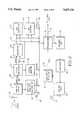
- FIG. 1is a schematic diagram of a communication system including a CSMA/CD wireless link according to the present invention.
- FIG. 2is a schematic block diagram of a wireless station according to the present invention.
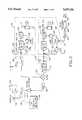
- FIG. 3is a schematic diagram of a transmitter according to the present invention.
- FIG. 4is a schematic diagram of a receiver according to the present invention.
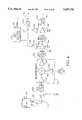
- FIG. 5is a schematic diagram of the collision detection circuitry for use in the transmitter of FIG. 3.
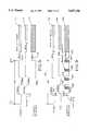
- FIG. 6is a schematic diagram of the wireless header used with the data packets according to the present invention.
- FIG. 7illustrates the operation of the wireless header with two packets that are transmitted nearly at the same time.
- FIG. 8illustrates the operation of the wireless header with two packets that are transmitted slightly offset in time, but which have a unique bit sequence which matches during the overlapping transmission.
- FIG. 9illustrates the effect of echoes or internal filter settling times on the wireless header according to the present invention.
- FIG. 10is a schematic diagram of the collision detection circuitry on the receiver.
- FIG. 11is a schematic diagram illustrating the process of sensing collisions using the drain of a FET.
- FIG. 12is an equivalent circuit diagram used in analyzing the mixing action on the drain of a FET.
- FIG. 13are signal graphs showing the mixing action on the drain of an FET.
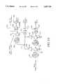
- FIG. 14illustrates the process of detecting collisions using a non-linear mixer in a wireless transmitter.
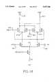
- FIG. 15is a schematic diagram illustrating the principle of collision detection in a receiver.
- FIG. 16provides a more detailed schematic diagram of the amplifier and full wave detecting stages in the receive collision detect circuitry of FIG. 10.
- FIG. 17is a circuit level schematic of a limiting amplifier used in the circuit of FIG. 16.
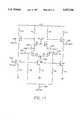
- FIG. 18is a circuit level schematic of a multiplier used in the circuit of FIG. 16.
- FIG. 1shows a local area network including a wireless link according to the present invention.
- the systemincludes a CSMA/CD wired LAN 10, such as a standard Ethernet system. Coupled to the wired LAN are a plurality of end stations 11, 12 as is standard in the art. Also, coupled to the wired LAN 10, is an access point 13 for communication with wireless stations, including wireless station WSTA 1 and wireless station WSTA 2.
- the access pointhas a typical range having a boundary as illustrated by the dotted line 13, which is defined by the receiver and transmitter technology used to define a basic service area.
- the preferred system according to the present inventionis implemented using a relatively narrow band frequency modulated NRZ channel in the 2.4 GHz ISM band.
- the channel bandwidth in the preferred systemis between 7 and 14 MHz. This channel allocation system allows for allocating a plurality of channels within the ISM band for adjacent basic service areas.
- each wireless stationin order to gain control of the communication channel, each wireless station must establish that no other stations are currently transmitting. Thus, the status of the receivers is checked to determine whether the carrier is free. If the carrier is free, then it begins transmitting. It is possible that two stations within the BSA will attempt to transmit at or near the same time under this protocol. Thus, a mechanism to detect collisions between simultaneous or near simultaneous transmissions is needed, such as is well known in the wired Ethernet LAN environment. However, this presents unique difficulties in the wireless environment.
- FIG. 2provides a block diagram of a wireless station according to the present invention.
- the wireless stationincludes an antenna 20 coupled to an analog receiver 21.
- the analog receiverproduces an analog NRZ signal on line 22 which is applied to the clock recovery circuit 23.
- the clock recovery circuitproduces a data signal on line 24 and a clock signal on line 25 which are supplied to a dewhitening circuit 26.
- the dewhitening circuitoutputs a dewhitened data signal on line 27.
- the data on line 27 and clock on line 25are supplied to a CRC generation circuit 29. Also, the signals on lines 27 and 25 are supplied through a CRC compare circuit 30, which compares the CRC supplied by the generate circuit 29 across line 99 with the CRC in the encapsulated packet. The CRC compare circuit 30 generates a data error signal on line 35 in the event the CRC in the received packet does not match the CRC generated by the generate circuit 29.
- an amplitude monitor and collision detector 31coupled to the analog receiver 21 is an amplitude monitor and collision detector 31.
- the circuit 31monitors the amplitude of the received signal to detect anomalies which are typical of erroneous data, and produces an amplitude error signal 33 when the amplitude of the received signal varies in an anomalous manner typical of erroneous data. Also, intermodulation products on the received signal which are typical of colliding transmissions are detected. If a collision is detected, then a collision signal is applied on line 43 to the processor 36.
- phase monitor circuit 32is coupled with the clock recovery circuit 23 according to the present invention which monitors changes in phase in transitions in the NRZ data stream 22.
- Phase monitor 33generates a phase error signal on line 34 in the event an anomaly in phase of the NRZ data stream is detected which is typical of erroneous data.
- the data on line 27, the clock on line 28, and the error signals on lines 33, 34 and 35are supplied to a processor 36.
- the processor 36passes the received data frame for higher protocol level processing and possibly on line 45 to a wired segment of the LAN. Also, if an error signal or collision signal is received, the processor 36 produces a collision detected, or retry, packet to send to the source of the packet. Further, the processor 36 may generate its own packets to be transmitted and supply such packets on line 28.
- a wireless header and wireless CRCare applied to a packet on line 28 in a wireless header and CRC generation block 37.
- the encapsulated wireless packetis applied to a whitener circuit 38 which whitens the NRZ data to increase the number of transitions in the packet to assist clock recovery at the receiver.
- the encapsulated wireless packetis then applied to an analog transmitter 39 and coupled into the medium through antenna 40.
- the antennae 20 and 40could be the same antenna, or antenna system, shared between the transmitter and receiver.
- a collision detector 41Coupled to the antenna 40 or the transmitter 39 is a collision detector 41.
- the collision detector 41monitors the state of the transmit antenna 40 during transmissions to detect collisions based on intermodulation products produced by the mixing of the transmitted signal from the analog transmitter 39 and signals received from other sources on the antenna 40. Using information about the known characteristics of transmitted data packets, such as the header described below, within the wireless network, the intermodulation products can be analyzed to detect particular characteristics of the intermodulation products which indicate a collision between digital data signals transmitted in the wireless link. If a collision is detected, then a signal is produced on line 42 and supplied to the processor 36. The processor then executes a backoff and retry sequence, such as the common backoff and retry sequences executed in Ethernet local area networks.
- the wireless header produced in block 38has characteristics which enhance the intermodulation products detected by the detector during collision.
- a transmitter for the preferred systemcan be understood with respect to FIG. 3.
- the transmitterreceives NRZ input data on line 100. It is applied to a data whitener 101 which produces a NRZ stream on line 102 having an increased number of data transitions.
- This signalis applied to a gaussian low pass filter 103 which produces a frequency modulation signal on line 104 which is coupled to a summing junction 105 in a phase locked loop 106.
- the phase locked loop 106is coupled to a crystal oscillator 107.
- the output of the oscillator 107is coupled to a phase detector 108.
- the output of the phase detectordrives a loop filter 109.
- the output of the loop filter 109is mixed with the data signal from line 104 in summing junction 105.
- the output of the summing junction 105drives the voltage controlled oscillator 110.
- the output of the voltage controlled oscillatoris supplied to a divide-by-N circuit 111.
- the output of the divide-by-N circuit 111is supplied as input to the phase detector 108 to complete the phase locked loop.
- the output of the phase locked loopis supplied on node 112 at the output of the voltage controlled oscillator 110.
- This signalis coupled through a switch generally 113 which is operated in the transmit position in the example shown, and coupled into a divide-by-2 circuit 114.
- the output of the divide-by-2 circuitis applied to a mixer 115.
- the transmitterincludes a second phase locked loop 116 which is driven by a crystal oscillator 117.
- the output of the crystal oscillator 117is applied to a phase detector 118.
- the output of the phase detector 118is supplied to a loop filter 119 which drives a voltage controlled oscillator 120.
- the output of the voltage controlled oscillator 120is applied to node 121 as the output of the phase locked loop, and back to a divide-by-N circuit 122 which is supplied as input to the phase detector 118.
- the phase locked loop 116operates at 1.927 to 1.997 MHz depending on the particular channel in which the transmitter is operating.
- the output of the phase locked loop 116is applied to a switch generally 139 which is set in a transmit position in this drawing.
- the output of the switch 139 in the transmit positionis coupled to the mixer 115, where it is mixed with the output of the divide-by-2 circuit 114.
- This mixersupplies a signal through a bandpass filter 125.
- the output of the bandpass filter 125is supplied to a power amplifier 126 and coupled through a switch 127 to the transmit antenna 128.
- the transmitterconsists of two independent phase locked loops 106, 116.
- Each phase locked loopis locked to a crystal oscillator frequency reference.
- the phase locked loop 116provides a frequency reference for the channel in which the transmitter operates.
- the phase locked loop 106provides a modulated offset frequency which is added to the reference from phase locked loop 116 during transmit.
- the switches 139 and 113allow switching between transmit and receive modes within a few microseconds.
- a frequency of 479.5 MHz(equal to the intermediate band frequency) is added to a signal of slightly less than 2 MHz to set up the communication channel.
- Maintaining the phase locked loop 106 at 959 MHzallows this loop to remain free running during the receive mode without interfering with the intermediate band processing in the receiver.
- the signalis divided by two during transmit only.
- the datais passed through a whitening or scrambling circuit prior to the gaussian low pass filter 103.
- the whitenerinsures that the NRZ data stream has no DC component. This assists keeping the phase locked loop 106 locked to the channel center frequency.
- the collision detector 130is tapped into the signal line across line 131. More details concerning the implementation of the collision detector 130 are provided below with respect to FIG. 5.
- FIG. 4is a schematic diagram of the receiver according to the present invention.
- the receiverincludes a first antenna 150 and a second antenna 151.
- a switch 152selects the antenna having the best received signal.
- the antennaeare coupled through switch 127 to either the transmit circuitry or the receive circuitry.
- the switch 127is coupled to the receive circuitry.
- the output of the antennais supplied through a bandpass filter 153 into a down converter 154.
- the down converterincludes an amplifier 155 which drives a mixer 156.
- the other input of the mixer 156is received from amplifier 157 driven by the signal on node 121 through the switch 122 shown in FIG. 3.
- the output of the mixer 157is supplied through amplifier 158 to a bandpass filter 159.
- the output of the bandpass filter 159is supplied through an intermediate frequency amplifier 160 to a second stage bandpass filter 161.
- the output of the second stage bandpass filter 161is supplied to a second stage intermediate frequency amplifier 162.
- the output of the amplifier 162is supplied through a quadrature detector 163 to produce an analog NRZ signal on line 164.
- the intermediate frequency amplifier 160also produces an output on line 165 which is coupled through a full wave detector 166 to produce an analog DC value at node 167.
- Node 167is also driven by the output of amplifier 162 through full wave detector 168.
- Node 167is coupled through an analog to digital converter 169 to supply a digital receive signal strength indication signal on line 170.
- Node 167is also coupled to the collision detector circuit 175 which detects intermodulation products characteristic of collisions between received data transmission signals as described below in more detail.
- the receive signal strength indicator on line 170is used to determine whether the received signal power is high enough to ensure the specified bit error rate for the receiver.
- the bit error rate for the receiverdepends on the overall noise figure for the receiver design. However, other errors possible in the wireless environment may occur during reception of an otherwise good signal which cause the receive signal strength to fluctuate. Thus, by monitoring the receive signal strength indication on line 170, errors may be detected in a receive data packet.
- the receiverincludes two antennae 150 and 151 to provide spatial diversity to combat multipath effects.
- An input bandpass filteris used to eliminate any signals outside the ISM band. After the filters and switches, the signal is fed to the down converter where it is converted to a 479.5 MHz intermediate frequency band signal.
- This intermediate frequency bandis chosen because of the availability of small, inexpensive surface acoustic wave (SAW) filters. SAW filters have a very sharp pass band to stop band rolloff characteristics, and excellent stop band attenuation. Thus, the filters 159 and 161 are implemented using SAW filters.
- the first SAW filter 159is used to knock out any out of band signals at or below the level of the weakest desired signal for the system.
- the second SAW filtereffectively eliminates any residual out of band energy.
- Both intermediate signal amplifiers 160 and 162act not only as gain stages but as limiting amplifiers.
- each amplifier stagedrives a full wave detector 166, 168. Summing the outputs of the full wave detectors provides a received signal strength indicator function. This received signal strength indicator function produces a voltage which is logarithmically proportional to amplitude. The voltage is digitized in the analog to digital converter 169 to give the processor an indication of the power level of the receive signal.
- the receive signal power levelnominally ranges between -40 dBm and -75 dBm.
- the receive signal strength circuitrymust cover a total dynamic range of 45 dB. Quantizing the signal on node 167 to 5 bit resolution gives a resolution level of 1.4 dB over this dynamic range.
- the output of the quadrature detectorprovides an analog signal corresponding to the transmitted NRZ data.
- This analog signalis fed to a data and clock recovery circuit to produce a recovered NRZ data and clock.
- FIG. 5is a schematic diagram of the collision detection circuitry for the transmitter.
- the amplifier 126 of FIG. 3includes a power amp FET transistor 200. It receives the transmit signal on its gate 201 from the output of the bandpass filter 125.
- the drain of the FET 200is coupled to the antenna 128 across an inductive tap 215 to a 5 volt supply 202.
- the 5 volt supply 202is also coupled across capacitor 203 to ground.
- the inductive tap 201supplies a signal to the input on line 213 of a gaussian bandpass filter 204.
- This filterhas a pass band from 2.5 MHz to 5 MHz and is designed with zeroes at adjacent channel downconverted center frequencies to attenuate signals in adjacent channels which are spaced, for example, by 14 MHz.
- the output of the first filter 204is supplied to a gain stage 205 which drives a second gaussian bandpass filter 206 having similar frequency characteristics.
- the output of the second filter 206is supplied to a gain stage 207 which drives a full wave detector 208.
- the output of the full wave detector 208is an analog DC value which is connected to a comparator 209.
- a detection thresholdis supplied on line 210 to the comparator 209.
- a detection strobe 211is supplied to the comparator 209 to control the timing of the threshold detection.
- the collision detection circuit of FIG. 5converts any frequency difference between 2.5 MHz and 5 MHz into a voltage. If there is no colliding signal, or if the colliding signal has the same frequency as the local transmitted signal, there will be no signal at the collision detection circuit output during the decision interval.
- the power FET 200has a non-linear response to colliding signals on the antenna 128.
- the intermodulation product signalis tapped off the amplifier drain power supply terminal and fed to a first gaussian bandpass filter 204.
- the action of the FET being driven to limiting by the transmit up-convertercauses a non-linear response which converts any colliding signal from the antenna to a low frequency.
- Each gaussian bandpass filterhas a pass band from approximately 2.5 MHz to 5 MHz and is designed with zeroes at adjacent channel downconverted center frequencies to attenuate signals in the adjacent channels.
- Two gain stages and another filteramplify and further filter the signal before it is presented to the full wave detector 208. Each gain stage has a gain of about 45 dB.
- the full wave detector 208operates as an envelope detector, producing a voltage proportional to the amplitude of the sine wave at the output of the second gain stage 207.
- the output of the full wave detectoris sampled by an analog latching comparator.
- the detected signalis compared to a preset detection threshold on line 210. If the output of the full wave detector is above the detection threshold during the low to high transition of the strobe signal on line 211, which occurs at the end of each decision interval, a logic one will appear at the latching comparator output. No collision has occurred if, during every decision interval, the output of the collision detection circuit is zero.
- FIG. 6shows basic form of a wireless header according to a preferred embodiment. It includes a first segment 250 of unmodulated carrier, followed by a 14 bit segment 251 providing a clock reference field, a third segment 252 of unmodulated carrier, a fourth segment called the UBS for unambiguous bit sequence 253, and a final segment of unmodulated carrier 254.
- the unmodulated carrier segments 250, 252 at 254may not be required for a given implementation.
- the headerstarts with 8 bits of unmodulated carrier in field 250, followed by 14 bits of alternating ones (2.5 MHz above channel center frequency) and zeroes (2.5 MHz below channel center frequency).
- Thisserves the dual purpose of allowing the collision detection circuit in the transmitting wireless LAN station to initially settle, and provides a means for the receiving wireless LAN to achieve lock on the clock prior to recovering the individual bits of the UBS in field 253.
- a short two bit period of unmodulated carrier in field 252provides a start of frame indicator for the receiving station so that it can decode the UBS.
- Each symbol of the UBSis really 16 bits long. This provides 1.6 microseconds for each symbol in the UBS to allow echoes to die out and to allow the filters in the collision detection circuit to settle.
- the entire UBSis 240 bits (15 symbols) long, which allows for 2 15 different UBS symbols. Note that if a UBS symbol is a "1”, then 16 consecutive ones are sent. Likewise, if the UBS symbol is "0”, then 16 consecutive zeroes are sent.
- the preamblefinishes with a period of unmodulated carrier 254.
- the decision on whether or not a collision has been detectedis made.
- FIG. 7illustrates operation of the wireless header based on the UBS sequence.
- a first tracegenerally 260 is shown which represents a first packet (Packet 1).
- a second trace 261is shown representing a second packet (Packet 2).
- a third trace 262illustrates the difference frequency intermodulation product produced by collision of the two packets.
- a UBS segmentis illustrated in field 263.
- the UBS of the second trace 261falls in the same field for packets which are transmitted at essentially the same time.
- the circuitdetects collisions during transmit as long as the colliding signal has a different frequency than the signal that is being transmitted at some point shortly after the start of the packet. This happens automatically during the body of the packet, since each transmitter is basically FM modulated with a different, usually uncorrelated data sequence. However, it is desirable to detect the collision as soon as possible, rather than waiting for the preamble which is usually identical for all packets in a CSMA/CD wired network, to finish.
- UBSa pseudo-random data bit stream which is assigned to each wireless station and access point, and intended to be different for each such station.
- This bit streamis applied at the start of the packet to allow for collision detection early in the packet. This ensures that at least one moment during the beginning of the packet, the UBS sequences will mismatch and the intermodulation products will be enhanced and indicate a collision.
- the transmitter in the preferred systemuses GMSK modulation to conserve bandwidth.
- the figureillustrates a minimum shift key transmit signal with the frequency changing substantially instantaneously plus and minus 2.5 MHz above and below the carriers in frequency.
- the action of the gaussian low pass filterwould cause a GMSK signal to smoothly change from one frequency to another with no sharp edges. This action ensures that the transmitted signal is narrow band.
- the sharp edgesare used in FIG. 7.
- FIG. 8illustrates this sequence.
- the first trace 270represents a packet which is transmitted at time 271.
- the second trace 272is illustrated which begins transmitting at time 273. Because of the inadvertent alignment of the UBS sequences for the two traces 270, 271, no frequency mismatch is detected until the end of the UBS sequence at point 274 for the first packet. Because of the short interval 275 at the end of the UBS which is set at the carrier frequency, an interval 276 in the frequency difference trace 277 is produced, at which a 2.5 MHz difference frequency is detected.
- the collision detection circuitryIn a wireless environment attempting to detect collisions between transmissions from separate sources, the collision detection circuitry must be capable of distinguishing between echoes of the transmitted signal, and actually colliding transmissions from other sources.
- the transmitterwill have a characteristic range, which defines a characteristic echo settling time.
- the round trip for this signalmay be on the order of a bit period or so, and produce a reflected signal which will be a different frequency than the transmitted signal from the transmitter. This will be indistinguishable from a colliding packet.
- echoesare handled by letting the period of each bit in the unambiguous bit sequence to be at least a few data bit periods long and controlling the timing of the collision detect strobe. This allows the system to wait long enough for echoes to return to the transmitter before determining whether a collision has occurred.
- a settling time on the order of 100 nanosecondswill be sufficient for echoes to die out, taking into account propagation path loss for round trip echoes as well as effective radar cross section of the object causing the reflected signal.
- the settling timemay be further limited by component settling characteristics in the circuitry, such as filter settling times.
- FIG. 9illustrates a way the echo problem is handled.
- a packet on trace 280is transmitted having a UBS 281.
- the echois illustrated on trace 282 which is delayed in time by an interval generally 283.
- the difference frequency trace 284will produce an interval 285 during which a difference frequency is detectable.
- the detection of collisions between echoesis avoided by strobing the collision detect comparator 209 during the intervals 286, 287, 288, and 289 which occur just prior to changing the value of the symbol in the UBS in the packet 280.
- a strobe during interval 286will avoid a false collision reading due to echoes which would occur during the interval 290.
- a strobe during the interval 287avoids echoes during interval 291.
- the decision during interval 289avoids echoes during the interval 292.
- the collision detection circuitlooks for the presence of any signal lying in the frequency bands between 2.5 MHz and 5 MHz on either side of the channel center frequency during transmit.
- the collision detection circuitis thus quite simple. In this aspect, it cannot distinguish between interference from another wireless station, the access point or a jammer. It simply knows that there is some interfering signal in close proximity to the channel center frequency. This causes the station to switch back to the receive mode where it can better evaluate the nature of the interfering signal.
- the settling time of the filters within the collision detection circuitrywill ultimately determine the length and position of the decision intervals shown in FIG. 9.
- a settling time of about 1.5 to 2 microseconds for the filters to fall below the minimal threshold level of detection each time the transmitted frequency is changed,is provided.
- the threshold level provided by the signal on line 210 of FIG. 5is chosen to be about one half to two thirds the maximum detected output level of the weakest desired signal.
- the settling timecan be improved by using a larger bandwidth filter.
- the upper bandshould be kept as low as possible to adequately attenuate out of band signals from adjacent channels, to prevent false alarms.
- a good alternative filtermight be a transitional gaussian bandpass filter which has almost as good a pulse response as a standard gaussian filter, with better stop band attenuation.
- An optimum filtermight be a matched filter that looks for the expected shape and frequency of the difference signals coming off the drain of the power amplifier FET, or some form of digital finite impulse response (FIR) filter.
- the wireless preambleneeds certain characteristics to improve collision detection during transmit. It needs two frequencies to be different at some point in time, and it needs to allow sufficient time for the filters and echoes to settle out before making a collision detection decision. However, additional features may be added to the preamble. Thus, a preamble having the clock recovery field 251 is provided.
- the receiveralso includes a collision detector as illustrated in FIG. 10. This is necessary because of the so called hidden terminal problem, in which one wireless station, such as wireless station WSTA 1 in FIG. 1 may be transmitting to the access point 13, while a second wireless station such as wireless station WSTA 2 in FIG. 1 also transmits. Because of the distance between the wireless stations, they may not be able to receive each other's signals. Thus, the access point 13 needs a receiver capable of detecting the collision.
- Collisionsmay be detected at the access point by merely assuming that whenever an error is detected at the access point, a collision is occurring. This works well if the colliding signals are close together in amplitude. However, an interfering signal may be much lower in magnitude than other signals in the wireless network. Further, a weak signal, which might be a valid signal, may be sufficiently lower in magnitude than another, that the low magnitude signal does not cause errors in the signal.
- FIG. 10illustrates a schematic diagram of a collision detection circuitry for use with the receiver of FIG. 4, as described above.
- the down converter 154applies a signal to a bandpass filter 159.
- this bandpass filter 159as well as the other components of the receiver are illustrated with the same reference numbers as used in FIG. 4. These elements are not described again.
- the collision detectorincludes the gaussian bandpass filter 350, which supplies an amplifier 351.
- the output of the amplifier 351is coupled to 352.
- a receive collision threshold signalis applied on line 353 to the latching comparator 352.
- the latching comparator 352produces a collision detect signal on line 354 which indicates collisions between received signals when strobed by a STROBE signal as shown.
- the receive signal strength indicatorproduces a voltage on node 167 which is logarithmically proportional to the amplitude of the received signal.
- the action of the full wave detectors 166 and 168is non-linear, and produces intermodulation products that include the difference frequency produced by the UBS portion of wireless packets when received simultaneously.
- the collision detect circuitcan be used to selectively filter and amplify this low level 5 MHz envelope fluctuation in the case when weak and strong signals are colliding. In this way, the circuitry already built in to the receiver is used to detect simultaneously transmitted signals. However, alternative systems might rely on a separate set of filters and detectors to sense the 5 MHz beat signals. The action of the SAW filters in the receiver prevent interference from adjacent and non-adjacent channels. Thus a simple filter can extract a 5 MHz frequency difference signal.
- the receive collision detect circuitryis only necessary in the environments in which a hidden terminal is possible. When a system guarantees that all possible transmitters in the network can receive the signal from others, then a transmit only collision detect system may be sufficient.
- FIGS. 11-18more details concerning the collision detection process of the present invention are provided.
- FIGS. 11-14are related to the process of detecting collisions based on producing intermodulation products.
- FIGS. 15-17address the receiver collision detection principle, and a detailed implementation of circuitry for detecting received collisions.
- FIG. 11illustrates the process of sensing collisions via the drain of a power MESFET in the amplifying stage driving the output antenna on the transmitter.
- the circuitincludes a power MESFET B1 having its source coupled to ground and its drain connected to an output matching network 400.
- the gate of the MESFET B1is connected to an input matching network 401.
- the input matching network 401is driven by the driving stage of the amplifier, which is represented in FIG. 11 by an equivalent circuit 402.
- the output matching network 400is coupled to line 403 from the antenna, which is represented by the equivalent circuit 404.
- the output matching network 400is connected between the MESFET B1 and node 405 at which a bypass capacitor C BYP is connected.
- Bypass capacitor C BYPhas a value of about 10-100 picoFarads to establish an AC ground at about 2.4 GHz.
- Intermodulation (IMD) productsare produced at node 405 from the drain of MESFET B1 in the current I DD from the power supply V DD .
- the equivalent circuit 402 of the driving stageincludes a voltage source V DRV , and a resistor R DRV of about 50 ohms in a matched 50 ohm circuit.
- the input matching network 401includes the capacitor C1 which is connected between the resistor R DRV and node 406. Capacitor C2 is connected between node 406 and ground.
- An inductor L1is connected between node 406 and the gate of MESFET B1. Also, the resistor R1 is connected between the gate of MESFET B1 and ground.
- the output matching network 400includes an inductor L2 connected between the drain of MESFET B1 and node 405. Also, the output matching network 400 includes a capacitor C3 connected between the drain of the MESFET B1 and line 403.
- the equivalent circuit of the antenna 404matches the equivalent circuit of the driving stage, including a 50 ohm resistor R ANT , and a voltage source V ANT .
- FIG. 12illustrates the equivalent circuit for the voltage V A across the antenna. It includes a current source I D , and an impedance Z OUT (t) which varies with time.
- the antenna equivalent circuitincludes the 50 ohm resistor and the voltage source V ANT .
- This equivalent circuitcan also be represented as illustrated by FIG. 12, by an equivalent circuit including the current source I D , the impedance Z OUT (t), and an antenna equivalent circuit based on a 50 ohm resistor connected between V A and ground, and a current source V ANT /50.
- the voltage V Acan be calculated as shown in FIG. 12 at equation 1.
- FIG. 13provides a simplified illustration of the result of the operation of the equivalent circuit when both signals are near the same frequency.
- a first graphillustrates the voltage V ANT as a periodic signal.
- a second graphillustrates the current I D as a rectified signal.
- the impedance Z OUT (t)is illustrated in FIG. 13 as an offset square wave.
- equation 1is applied to calculate V A , then the waveform 419 of FIG. 13 is produced.
- V Ahas the enlarged shape 420, as illustrated in FIG. 13.
- the impedance Z OUT (t)is low, then the attenuated shape 421 is produced.
- Waveform V Athus includes the intermodulation products used by the mixing action at the drain of the driving MESFET.
- FIG. 14An alternative design is shown in FIG. 14 for producing intermodulation products using a non-linear mixer.
- a transmit signal from the upconverteris provided on line 450.
- the signalis supplied through power amplifier 451 to node 452.
- Node 452is coupled through a RF bandpass filter 453 to the transmit antenna 454.
- node 452is coupled to a high impedance transformer 455.
- the output side of the high impedance transformeris tapped at the center with a bias voltage V BIAS .
- a first side of the transformeris connected to the gate of FET B1, while a second side of the transformer 455 is coupled to the gate of FET B2.
- the sources of FET's B1 and B2are coupled together at current source 456.
- FET's B1 and B2are coupled to the supply voltage V DD .
- V Aa fullwave rectified signal
- This signalis supplied across resistor R1 as +V OUT on line 457.
- a capacitor C1is connected between line 457 and ground.
- a reference voltageis produced by FET's B3 and B4, which have their sources coupled to node V B , and their gates connected to a bias potential V BIAS .
- the drains of FET's B3 and B4are coupled to the supply voltage V DD .
- the node V B at the common sources of FET's B3 and B4is coupled across resistor R2 to line 458 as the -V OUT signal.
- Capacitor C2is connected between line 458 and ground.
- current source 459is connected between node V B and ground.
- the circuit of FIG. 14is particularly suited to implementation on a monolithic microwave integrated circuit.
- the non-linear mixing action provided by the common source FET's B1 and B2produces the intermodulation products in the signal V A necessary for collision detection as described above.
- FIGS. 15 through 18illustrate the receiver collision detection process.
- a receive signalis detected at antenna 500 and is supplied through a low noise amplifier 501 to mixer 502.
- Local oscillator 503is mixed with the signal received from the antenna, at the mixer 502.
- the resulting signalis supplied through an intermediate frequency bandpass filter 504 to an intermediate frequency amplifier 505.
- a linear waveformis produced at the output of the amplifier 505 and coupled across line 506 to the rest of the receiver circuitry.
- Intermodulation productsare produced by supplying the linear waveform at the output of the amplifier 505 through a non-linear circuit element 507.
- the output of the circuit element 507includes the intermodulation products on line 508, which will then be supplied through a low pass filter and detector circuitry to produce a collision detect signal at the receiver.
- FIGS. 16 through 18illustrate a preferred embodiment of the amplifiers and the fullwave detectors, such as amplifier 162 and fullwave detector 168, used in the receiver collision circuitry of FIG. 10.
- an intermediate frequency amplifiersuch as amplifier 162 may include a four stage circuit as shown in FIG. 16. It receives the intermediate frequency input as a balanced two line signal on lines 600 and 601. Lines 600 and 601 are AC coupled through capacitors C1 and C2, respectively, to a first limiting amp 603. The outputs of the limiting amp 603 include true and compliment versions, and are AC coupled through capacitors C3 and C4 to a second limiting amp 604. Similarly, limiting amp 604 drives the input to limiting amp 605 through AC coupling capacitors C5 and C6.
- the outputs of amplifier 605are AC coupled through capacitor C7 and C8 to the inputs of amplifier 606.
- the outputs of the amplifier 606are AC coupled through capacitors C9 and C10 to the amplifier output stages on lines 607 and 608.
- the circuit schematic for one of the amplifier stagesis described with respect to FIG. 17.
- the full wave detectorconsists of multiplier circuits MULT1, MULT2, MULT3, and MULT4.
- the first multiplier MULT1receives as input, the signal supplied to the input of the first amplifier 603, and a signal supplied at an output of the first amplifier 603.
- the signals on the multiplier output terminals on lines 609 and 610have the shape illustrated at trace 611.
- the second multiplier MULT2has its inputs connected to the inputs of the second amplifier 604, and to outputs of the second amplifier 604.
- the outputs of the multiplier MULT2are connected to lines 609 and 610 and produce signals having the shape illustrated at trace 612.
- the multiplier MULT3is connected to the inputs and outputs of the third amplifier 605, and has its outputs connected to line 609 and 610.
- the outputs of the third multiplier MULT3have the shape illustrated at trace 613.
- the fourth multiplier MULT4is connected across the fourth amplifier 606. Its outputs are connected to lines 609 and 610 and produce a signal having a shape illustrated at trace 614.
- the inputs to the collision detect comparatorare provided on lines 615 and 616 which are connected to lines 609 and 610.
- Line 615is connected to the power supply V CC through resistors R3 and R1.
- line 616is connected to the power supply V CC through resistors R4 and R2.
- a receive signal strength indication RSSI outputis provided on line 617.
- the other RSSI outputis provided on line 618.
- a capacitor C FILTERis connected between lines 617 and 618.
- FIG. 17provides a schematic diagram of a limiting amplifier, such as might be used as amplifiers 603 through 606 in the circuit of FIG. 16.
- the inputs to the amplifierprovided on lines 650 and 651 at the base of transistors Q1 and Q2 as inputs to the multiplier.
- the input terminals on lines 650 and 651are connected across resistors R8 and R9, respectively, to a bias potential V BIAS3 at node 658.
- the emitters of transistors Q1 and Q2are connected through resistors R3 and R4, respectively, to node 652.
- Node 652is connected through the current source transistor Q8 and resistor R6 to ground.
- Current source transistor Q8has its base connected to a bias potential V BIAS2 on line 653.
- the collector of transistor Q1provides the minus output (-MULT) the multiplier on line 654, and the collector of transistor Q2 provides the positive output (+MULT) multiplier on line 655.
- the collector of transistor Q1is connected to the emitter of transistor Q3, which has its collector coupled across resistor R1 to the supply V CC .
- the base of transistor Q3is connected to the bias potential V BIAS1 .
- the collector of transistor Q2is connected to the emitter of transistor Q4 which has its collector connected across resistor R2 to the supply voltage V CC .
- the base of transistor Q4is connected to the bias V BIAS1 .
- the minus output (-OUT) of the amplifieris provided through emitter follower transistor Q5 which has its base connected to the collector of transistor Q3, and its emitter connected to line 655 providing the minus output.
- the positive output (+OUT)is provided through emitter follower Q6 which has its base connected to the collector of transistor Q4, and its emitter connected to line 657.
- the collector of the transistor Q5 and the collector of transistor of Q6are connected to the supply voltage V CC across resistors R10 and R11, respectively.
- the emitters of transistors Q5 and Q6are coupled to current source transistors Q7 and Q9, respectively.
- the emitter of transistor Q7is connected across resistor R5 to ground.
- the base of transistor Q7is connected to the bias voltage V BIAS2 on line 653.
- the emitter of transistor Q9is connected across resistor R9 to ground and the base of transistor Q9 is connected to the signal V BIAS2 .
- the multiplier used as the fullwave detectorsuch as multiplier MULT4 in FIG. 16, is shown in FIG. 18.
- This circuitconsists of transistors Q1 and Q2 which have their emitters coupled to node 670, which is connected to the collector of transistor Q5.
- the emitter of transistor Q5is connected to node 671.
- Node 671is connected to the collector of current source transistor Q7, which has its emitter connected across resistor R1 to ground.
- the base of transistor Q7is coupled to the bias potential V BIAS2 .
- an emitter coupled pairconsisting of transistors Q3 and Q4 is included.
- the emitters of transistors Q3 and Q4are connected to node 672.
- Node 672is connected to the collector of transistor Q6.
- the emitter of transistor Q6is connected to node 671.
- the inputs (+IN, -IN) to the multiplierare connected to the first stage (Q5, Q6) of emitter coupled pairs as illustrated.
- the positive multiplier input (+MULT)is supplied on line 673 to the bases of transistors Q1 and Q4.
- the negative multiplier input (-MULT)is connected on line 674 to the bases of transistors Q2 and Q3.
- the output of the multiplieris supplied on the minus sum (-SUM) line 609 and the plus sum (+SUM) line 610 to the load illustrated in FIG. 16 consisting of the resistors R1 and R4 and the capacitor C FILTER .
- the present inventionprovides a collision detection system for both receivers and transmitters in a wireless network.
- Collision detectionallows implementation of a full carrier sense multiple access with collision detection protocol in the wireless environment providing maximum network throughput. Further, the system is relatively simple to implement, sensitive and robust.
Landscapes
- Engineering & Computer Science (AREA)
- Computer Networks & Wireless Communication (AREA)
- Signal Processing (AREA)
- Physics & Mathematics (AREA)
- Nonlinear Science (AREA)
- Small-Scale Networks (AREA)
- Mobile Radio Communication Systems (AREA)
Abstract
Description
Claims (36)
Priority Applications (5)
| Application Number | Priority Date | Filing Date | Title |
|---|---|---|---|
| US08/359,539US5657326A (en) | 1994-12-20 | 1994-12-20 | Radio based collision detection for wireless communication system |
| JP8519983AJPH10511242A (en) | 1994-12-20 | 1995-12-19 | Apparatus and method for collision detection for wireless communication systems |
| AU46039/96AAU4603996A (en) | 1994-12-20 | 1995-12-19 | Radio based collision detection for wireless communication system |
| PCT/US1995/016636WO1996019877A1 (en) | 1994-12-20 | 1995-12-19 | Radio based collision detection for wireless communication system |
| GB9710461AGB2310978B (en) | 1994-12-20 | 1995-12-19 | Radio based collision detection for wireless communication system |
Applications Claiming Priority (1)
| Application Number | Priority Date | Filing Date | Title |
|---|---|---|---|
| US08/359,539US5657326A (en) | 1994-12-20 | 1994-12-20 | Radio based collision detection for wireless communication system |
Publications (1)
| Publication Number | Publication Date |
|---|---|
| US5657326Atrue US5657326A (en) | 1997-08-12 |
Family
ID=23414261
Family Applications (1)
| Application Number | Title | Priority Date | Filing Date |
|---|---|---|---|
| US08/359,539Expired - LifetimeUS5657326A (en) | 1994-12-20 | 1994-12-20 | Radio based collision detection for wireless communication system |
Country Status (5)
| Country | Link |
|---|---|
| US (1) | US5657326A (en) |
| JP (1) | JPH10511242A (en) |
| AU (1) | AU4603996A (en) |
| GB (1) | GB2310978B (en) |
| WO (1) | WO1996019877A1 (en) |
Cited By (62)
| Publication number | Priority date | Publication date | Assignee | Title |
|---|---|---|---|---|
| US5892759A (en)* | 1996-02-05 | 1999-04-06 | Nec Corporation | Data transmission control system for performing one-to-multiple site data transmission by the use of radio packet communication |
| US5910956A (en)* | 1996-11-05 | 1999-06-08 | Northrop Gruman Corporation | Random time interval generator |
| US5987033A (en)* | 1997-09-08 | 1999-11-16 | Lucent Technologies, Inc. | Wireless lan with enhanced capture provision |
| US6006271A (en)* | 1998-02-27 | 1999-12-21 | 3Com Corporation | Method and protocol for complete collision avoidance contention resolution in local area networks |
| US6005853A (en)* | 1995-10-13 | 1999-12-21 | Gwcom, Inc. | Wireless network access scheme |
| US6067291A (en)* | 1997-09-23 | 2000-05-23 | Lucent Technologies Inc. | Wireless local area network with enhanced carrier sense provision |
| US6072824A (en)* | 1998-01-23 | 2000-06-06 | Adc Solitra, Inc. | Circuit arrangement for reducing intermodulation in a bandpass filter system |
| US6075795A (en)* | 1999-04-07 | 2000-06-13 | Advanced Micro Devices, Inc. | Collision detection system for multiple stations in discrete multi-tone data communications network |
| US6157616A (en)* | 1996-05-31 | 2000-12-05 | Lucent Technologies | Adaptive methods for packet transmission over wireless networks |
| US6169744B1 (en)* | 1998-01-07 | 2001-01-02 | 3Com Corporation | Method and protocol for a medium access control layer for local area networks with multiple-priority traffic |
| WO2001076152A1 (en)* | 2000-03-31 | 2001-10-11 | Intel Corporation | Data collision detection in networks |
| EP1101307A4 (en)* | 1998-08-07 | 2002-04-10 | Ihab H Elzind | Cellular internet protocol modem network |
| US6381213B1 (en)* | 1997-09-08 | 2002-04-30 | Tut Systems, Inc. | Method and apparatus for detecting collisions on a network |
| US20020080024A1 (en)* | 2000-02-07 | 2002-06-27 | Tantivy Communications, Inc. | Maintenance link using active/standby request channels |
| US20030026283A1 (en)* | 2001-06-08 | 2003-02-06 | Broadcom Corporation | System and method for detecting collisions in a shared communications medium |
| US6539028B1 (en) | 1998-12-09 | 2003-03-25 | Kent Ridge Digital Labs | CSMA/CD wireless LAN |
| US6545994B2 (en)* | 2000-02-23 | 2003-04-08 | Tantivy Communications, Inc. | Access probe acknowledgment including collision detection to avoid oversetting initial power level |
| WO2003047290A1 (en)* | 2001-11-30 | 2003-06-05 | Telefonaktiebolaget Lm Ericsson (Publ) | Interference measurements in a wireless communications system |
| US6643296B1 (en)* | 1997-07-04 | 2003-11-04 | Fujitsu Limited | System for controlling frame collision |
| US20030206130A1 (en)* | 2002-05-03 | 2003-11-06 | Paul Husted | Method and apparatus for physical layer radar pulse detection and estimation |
| US6678321B1 (en) | 1998-09-15 | 2004-01-13 | Tut Systems, Inc. | Method and apparatus for transmitting and receiving a symbol over pots wiring using a multi-cycle waveform |
| US6735217B1 (en)* | 1998-09-15 | 2004-05-11 | Tut Systems, Inc. | Method and apparatus for detecting collisions on a network using multi-cycle waveform pulses |
| US6771774B1 (en) | 1999-12-02 | 2004-08-03 | Tut Systems, Inc. | Filter arrangement for shaping a pulse propagated over pots wiring, and a method of manufacturing the same |
| US20040160917A1 (en)* | 1999-06-22 | 2004-08-19 | Eliznd Ihab H. | Multibeam antenna for a wireless network |
| US6967937B1 (en) | 1999-12-17 | 2005-11-22 | Cingular Wireless Ii, Llc | Collision-free multiple access reservation scheme for multi-tone modulation links |
| US20050272423A1 (en)* | 2004-06-02 | 2005-12-08 | Stephens Adrian P | Adaptive polling of wireless devices |
| US20060154628A1 (en)* | 2002-05-27 | 2006-07-13 | Takuji Mochizuki | Receiver of carrier sense multiplexing connection method and interference suppressing method thereof |
| US20060192697A1 (en)* | 2003-08-08 | 2006-08-31 | Quick Ashleigh G | Collision detection in a non-dominant bit radio network communication system |
| US20060199587A1 (en)* | 2003-09-15 | 2006-09-07 | Broadcom Corporation, A California Corporation | Radar detection circuit for a WLAN transceiver |
| US20060205351A1 (en)* | 2005-03-14 | 2006-09-14 | Nec Corporation | DC offset cancel control method and transmitter/receiver |
| US20060203889A1 (en)* | 2005-03-08 | 2006-09-14 | Applied Research Associates, Inc. | Ultra-narrow bandwidth radio frequency communications link |
| KR100662267B1 (en)* | 1999-09-22 | 2007-01-02 | 엘지전자 주식회사 | Base station transmitting and receiving apparatus for receiving packet through common packet channel allocation method and common packet channel |
| US7245725B1 (en) | 2001-05-17 | 2007-07-17 | Cypress Semiconductor Corp. | Dual processor framer |
| US20070211751A1 (en)* | 2006-03-08 | 2007-09-13 | Lucent Technologies Inc. | Methods and systems for detecting collisions in access/utilization of resources of contention |
| US20070281638A1 (en)* | 2003-09-15 | 2007-12-06 | Broadcom Corporation | Radar detection circuit for a wlan transceiver |
| US7420986B1 (en)* | 1999-11-02 | 2008-09-02 | Broadcom Corporation | Method and apparatus for the detection and classification of collisions on a shared RF network |
| US7434143B2 (en) | 2003-06-24 | 2008-10-07 | Infineon Technologies Ag | Method and arrangement for detecting a collision in a communication network |
| US7551663B1 (en) | 2001-02-01 | 2009-06-23 | Ipr Licensing, Inc. | Use of correlation combination to achieve channel detection |
| US7746830B2 (en) | 1998-06-01 | 2010-06-29 | Interdigital Technology Corporation | System and method for maintaining wireless channels over a reverse link of a CDMA wireless communication system |
| US7773566B2 (en) | 1998-06-01 | 2010-08-10 | Tantivy Communications, Inc. | System and method for maintaining timing of synchronization messages over a reverse link of a CDMA wireless communication system |
| US7936854B2 (en) | 2002-11-15 | 2011-05-03 | Cypress Semiconductor Corporation | Method and system of cycle slip framing in a deserializer |
| US7936728B2 (en) | 1997-12-17 | 2011-05-03 | Tantivy Communications, Inc. | System and method for maintaining timing of synchronization messages over a reverse link of a CDMA wireless communication system |
| US20110103320A1 (en)* | 2009-10-29 | 2011-05-05 | Electronics And Telecommunications Research Institute | Contention-based data communication apparatus and method |
| US8134980B2 (en) | 1998-06-01 | 2012-03-13 | Ipr Licensing, Inc. | Transmittal of heartbeat signal at a lower level than heartbeat request |
| US8155140B1 (en) | 2008-11-25 | 2012-04-10 | Qualcomm Atheros, Inc. | Collision avoidance for a network system |
| US8155096B1 (en) | 2000-12-01 | 2012-04-10 | Ipr Licensing Inc. | Antenna control system and method |
| US8175120B2 (en) | 2000-02-07 | 2012-05-08 | Ipr Licensing, Inc. | Minimal maintenance link to support synchronization |
| US8274954B2 (en) | 2001-02-01 | 2012-09-25 | Ipr Licensing, Inc. | Alternate channel for carrying selected message types |
| US20120320887A1 (en)* | 2011-06-17 | 2012-12-20 | Microsoft Corporation | Wireless communications |
| US20130002038A1 (en)* | 2011-06-29 | 2013-01-03 | Jaesung Lee | Method for avoiding signal collision in wireless power transfer |
| US20140269758A1 (en)* | 2013-03-15 | 2014-09-18 | Echelon Corporation | Method and system of enhancing signal processing in a shared medium network |
| US8908654B2 (en) | 1998-06-01 | 2014-12-09 | Intel Corporation | Dynamic bandwidth allocation for multiple access communications using buffer urgency factor |
| US9014118B2 (en) | 2001-06-13 | 2015-04-21 | Intel Corporation | Signaling for wireless communications |
| US9042400B2 (en) | 1997-12-17 | 2015-05-26 | Intel Corporation | Multi-detection of heartbeat to reduce error probability |
| US9408216B2 (en) | 1997-06-20 | 2016-08-02 | Intel Corporation | Dynamic bandwidth allocation to transmit a wireless protocol across a code division multiple access (CDMA) radio link |
| EP2985864A4 (en)* | 2013-02-27 | 2016-09-28 | Hitachi Ltd | POWER SUPPLY APPARATUS, ELECTRICITY RECEIVING APPARATUS, ELECTRIC VEHICLE, CHARGING SYSTEM, AND CHARGING METHOD |
| US9525923B2 (en) | 1997-12-17 | 2016-12-20 | Intel Corporation | Multi-detection of heartbeat to reduce error probability |
| US9948754B2 (en) | 2016-02-18 | 2018-04-17 | Mitsubishi Electric Research Laboratories, Inc. | System and method for decoding asynchronously transmitted packets |
| US10178697B2 (en) | 2017-02-22 | 2019-01-08 | Mitsubishi Electric Research Laboratories | Systems and methods for separating collided packets in shared wireless channels |
| US10651957B2 (en) | 2018-03-28 | 2020-05-12 | Qualcomm Incorporated | Proximity detection using a hybrid transceiver |
| US10673479B2 (en)* | 2017-03-28 | 2020-06-02 | Qualcomm Incorporated | Range-based transmission parameter adjustment |
| US11165451B1 (en) | 2020-10-20 | 2021-11-02 | Rohde & Schwarz Gmbh & Co. Kg | Method and system for detecting presence of a bidirectional amplifier |
Families Citing this family (15)
| Publication number | Priority date | Publication date | Assignee | Title |
|---|---|---|---|---|
| IL121179A (en)* | 1997-06-27 | 2000-02-29 | Elpas Electro Optic Systems Lt | Method and system for avoiding collisions in an infra-red wireless network |
| RU2161863C2 (en)* | 1998-08-11 | 2001-01-10 | Государственное предприятие научно-производственная фирма "РАТЕКС" | Device for monitoring of operation of radio stations with pseudorandom retuning of operating frequency |
| AU760513B2 (en)* | 2000-02-16 | 2003-05-15 | Samsung Electronics Co., Ltd. | Apparatus and method for assigning a common packet channel in a CDMA communication system |
| DE60118254T2 (en)* | 2000-02-17 | 2006-08-17 | Samsung Electronics Co., Ltd., Suwon | Method for allocating a common packet channel in a CDMA communication channel |
| US7570657B1 (en) | 2000-12-15 | 2009-08-04 | Marvell International Ltd. | Autonegotiation between 1000Base-X and 1000Base-T |
| US7624197B1 (en) | 2000-12-18 | 2009-11-24 | Marvell International Ltd. | Apparatus and method for automatic speed downshift for a two pair cable |
| US7203851B1 (en) | 2001-04-03 | 2007-04-10 | Marvell International Ltd. | Method and apparatus for detecting and supplying power by a first network device to a second network device |
| US7161911B1 (en) | 2001-04-03 | 2007-01-09 | Marvell International, Ltd | Method and apparatus for autonegotiation between network devices |
| US7292596B1 (en) | 2002-03-26 | 2007-11-06 | Marvell International Ltd | Method and apparatus for automatic crossover and parallel detect |
| RU2231926C1 (en)* | 2002-11-14 | 2004-06-27 | Военная космическая академия | Monitoring device for pseudorandom operating frequency tuned radio stations |
| RU2275744C1 (en)* | 2004-12-07 | 2006-04-27 | Военно-Космическая Академия | Device for controlling operation of radio stations with pseudo-random readjustment of working frequency |
| US7545057B1 (en) | 2005-01-04 | 2009-06-09 | Marvell International Ltd, | Relay circuitry and switching circuitry for power-over-network devices |
| RU2292121C1 (en)* | 2005-07-05 | 2007-01-20 | Российская Федерация в лице МО РФ | Device for controlling operation of radio stations with pseudo-random adjustment of working frequency |
| ES2301349B2 (en)* | 2006-04-05 | 2009-02-01 | Universidad De Las Islas Baleares | PROCEDURE FOR RESOLVING COLLISIONS OF INFORMATION PACKAGES IN A RANDOM ACCESS NETWORK, COMMUNICATIONS SYSTEM AND COLLISION RESOLUTION DEVICE INCLUDED IN THIS SYSTEM. |
| US9130746B1 (en) | 2011-01-27 | 2015-09-08 | Marvell International Ltd. | Single pair PHY with auto-negotiation |
Citations (27)
| Publication number | Priority date | Publication date | Assignee | Title |
|---|---|---|---|---|
| US4336541A (en)* | 1980-08-08 | 1982-06-22 | The United States Of America As Represented By The Secretary Of The Air Force | Simultaneous signal detector for an instantaneous frequency measurement receiver |
| US4719458A (en)* | 1986-02-24 | 1988-01-12 | Chrysler Motors Corporation | Method of data arbitration and collision detection in a data bus |
| US4747101A (en)* | 1985-04-22 | 1988-05-24 | Nec Corporation | Method of determining optimal transmission channel in multi-station communications system |
| US4807222A (en)* | 1986-08-25 | 1989-02-21 | American Telephone And Telegraph Company At&T Bell Laboratories | Cordless accessed high-speed high-capacity local area networks |
| US4866788A (en)* | 1986-10-24 | 1989-09-12 | Michel Mouly | Process for controlling retransmission of messages from transmitting stations belonging to a cellular system |
| US4876742A (en)* | 1987-03-23 | 1989-10-24 | Gary Vacon | Apparatus and method for providing a wireless link between two local area network systems |
| US4975926A (en)* | 1989-03-30 | 1990-12-04 | Guenther Knapp | Wireless indoor data communication system |
| US5029183A (en)* | 1989-06-29 | 1991-07-02 | Symbol Technologies, Inc. | Packet data communication network |
| US5040175A (en)* | 1990-04-11 | 1991-08-13 | Ncr Corporation | Wireless information transmission system |
| US5099346A (en)* | 1988-01-27 | 1992-03-24 | Spectrix Corporation | Infrared communications network |
| US5103461A (en)* | 1989-06-29 | 1992-04-07 | Symbol Technologies, Inc. | Signal quality measure in packet data communication |
| US5123029A (en)* | 1991-06-21 | 1992-06-16 | International Business Machines Corporation | Broadcast-initiated bipartite frame multi-access protocol |
| US5142550A (en)* | 1989-06-29 | 1992-08-25 | Symbol Technologies, Inc. | Packet data communication system |
| US5157687A (en)* | 1989-06-29 | 1992-10-20 | Symbol Technologies, Inc. | Packet data communication network |
| US5164942A (en)* | 1990-09-06 | 1992-11-17 | Ncr Corporation | Antenna control for a wireless local area network station |
| US5166929A (en)* | 1990-06-18 | 1992-11-24 | Northern Telecom Limited | Multiple access protocol |
| US5181200A (en)* | 1990-10-29 | 1993-01-19 | International Business Machines Corporation | Handoff method and apparatus for mobile wireless workstation |
| US5220564A (en)* | 1990-09-06 | 1993-06-15 | Ncr Corporation | Transmission control for a wireless local area network station |
| US5231634A (en)* | 1991-12-18 | 1993-07-27 | Proxim, Inc. | Medium access protocol for wireless lans |
| US5274841A (en)* | 1990-10-29 | 1993-12-28 | International Business Machines Corporation | Methods for polling mobile users in a multiple cell wireless network |
| US5276703A (en)* | 1992-01-13 | 1994-01-04 | Windata, Inc. | Wireless local area network communications system |
| US5280498A (en)* | 1989-06-29 | 1994-01-18 | Symbol Technologies, Inc. | Packet data communication system |
| EP0594458A2 (en)* | 1992-10-23 | 1994-04-27 | Nec Corporation | Inter-cellular interference detection by cancelling data corruption events reported by mobile stations |
| US5339316A (en)* | 1992-11-13 | 1994-08-16 | Ncr Corporation | Wireless local area network system |
| US5369639A (en)* | 1990-09-06 | 1994-11-29 | Ncr Corporation | Local area network having a wireless transmission link |
| US5379290A (en)* | 1992-08-14 | 1995-01-03 | Ncr Corporation | Wireless local area network transmission system |
| US5422887A (en)* | 1991-11-27 | 1995-06-06 | Ncr Corporation | Medium access protocol for wireless local area network |
Family Cites Families (2)
| Publication number | Priority date | Publication date | Assignee | Title |
|---|---|---|---|---|
| US4574378A (en)* | 1982-06-14 | 1986-03-04 | Nec Corporation | Multiple access system and method |
| US5475869A (en)* | 1993-05-28 | 1995-12-12 | Nec Corporation | Radio base station capable of distinguishing between interference due to collisions of outgoing call signals and an external interference noise |
- 1994
- 1994-12-20USUS08/359,539patent/US5657326A/ennot_activeExpired - Lifetime
- 1995
- 1995-12-19AUAU46039/96Apatent/AU4603996A/ennot_activeAbandoned
- 1995-12-19JPJP8519983Apatent/JPH10511242A/ennot_activeCeased
- 1995-12-19WOPCT/US1995/016636patent/WO1996019877A1/enactiveApplication Filing
- 1995-12-19GBGB9710461Apatent/GB2310978B/ennot_activeExpired - Lifetime
Patent Citations (28)
| Publication number | Priority date | Publication date | Assignee | Title |
|---|---|---|---|---|
| US4336541A (en)* | 1980-08-08 | 1982-06-22 | The United States Of America As Represented By The Secretary Of The Air Force | Simultaneous signal detector for an instantaneous frequency measurement receiver |
| US4747101A (en)* | 1985-04-22 | 1988-05-24 | Nec Corporation | Method of determining optimal transmission channel in multi-station communications system |
| US4719458A (en)* | 1986-02-24 | 1988-01-12 | Chrysler Motors Corporation | Method of data arbitration and collision detection in a data bus |
| US4807222A (en)* | 1986-08-25 | 1989-02-21 | American Telephone And Telegraph Company At&T Bell Laboratories | Cordless accessed high-speed high-capacity local area networks |
| US4866788A (en)* | 1986-10-24 | 1989-09-12 | Michel Mouly | Process for controlling retransmission of messages from transmitting stations belonging to a cellular system |
| US4876742A (en)* | 1987-03-23 | 1989-10-24 | Gary Vacon | Apparatus and method for providing a wireless link between two local area network systems |
| US5099346A (en)* | 1988-01-27 | 1992-03-24 | Spectrix Corporation | Infrared communications network |
| US4975926A (en)* | 1989-03-30 | 1990-12-04 | Guenther Knapp | Wireless indoor data communication system |
| US5280498A (en)* | 1989-06-29 | 1994-01-18 | Symbol Technologies, Inc. | Packet data communication system |
| US5029183A (en)* | 1989-06-29 | 1991-07-02 | Symbol Technologies, Inc. | Packet data communication network |
| US5103461A (en)* | 1989-06-29 | 1992-04-07 | Symbol Technologies, Inc. | Signal quality measure in packet data communication |
| US5157687A (en)* | 1989-06-29 | 1992-10-20 | Symbol Technologies, Inc. | Packet data communication network |
| US5142550A (en)* | 1989-06-29 | 1992-08-25 | Symbol Technologies, Inc. | Packet data communication system |
| US5040175A (en)* | 1990-04-11 | 1991-08-13 | Ncr Corporation | Wireless information transmission system |
| US5166929A (en)* | 1990-06-18 | 1992-11-24 | Northern Telecom Limited | Multiple access protocol |
| US5164942A (en)* | 1990-09-06 | 1992-11-17 | Ncr Corporation | Antenna control for a wireless local area network station |
| US5369639A (en)* | 1990-09-06 | 1994-11-29 | Ncr Corporation | Local area network having a wireless transmission link |
| US5220564A (en)* | 1990-09-06 | 1993-06-15 | Ncr Corporation | Transmission control for a wireless local area network station |
| US5274841A (en)* | 1990-10-29 | 1993-12-28 | International Business Machines Corporation | Methods for polling mobile users in a multiple cell wireless network |
| US5181200A (en)* | 1990-10-29 | 1993-01-19 | International Business Machines Corporation | Handoff method and apparatus for mobile wireless workstation |
| US5123029A (en)* | 1991-06-21 | 1992-06-16 | International Business Machines Corporation | Broadcast-initiated bipartite frame multi-access protocol |
| US5422887A (en)* | 1991-11-27 | 1995-06-06 | Ncr Corporation | Medium access protocol for wireless local area network |
| US5231634A (en)* | 1991-12-18 | 1993-07-27 | Proxim, Inc. | Medium access protocol for wireless lans |
| US5231634B1 (en)* | 1991-12-18 | 1996-04-02 | Proxim Inc | Medium access protocol for wireless lans |
| US5276703A (en)* | 1992-01-13 | 1994-01-04 | Windata, Inc. | Wireless local area network communications system |
| US5379290A (en)* | 1992-08-14 | 1995-01-03 | Ncr Corporation | Wireless local area network transmission system |
| EP0594458A2 (en)* | 1992-10-23 | 1994-04-27 | Nec Corporation | Inter-cellular interference detection by cancelling data corruption events reported by mobile stations |
| US5339316A (en)* | 1992-11-13 | 1994-08-16 | Ncr Corporation | Wireless local area network system |
Non-Patent Citations (4)
| Title |
|---|
| Tsui, "Microwave Receivers With Electronic Warfare Applications", published by John Wiley & Sons, pp. 212-214. |
| Tsui, et al., "Instantaneous Simultaneous Signal Detecting", Microwave Journal, Dec., 1982, pp. 118-119 and 122. |
| Tsui, et al., Instantaneous Simultaneous Signal Detecting , Microwave Journal, Dec., 1982, pp. 118 119 and 122.* |
| Tsui, Microwave Receivers With Electronic Warfare Applications , published by John Wiley & Sons, pp. 212 214.* |
Cited By (112)
| Publication number | Priority date | Publication date | Assignee | Title |
|---|---|---|---|---|
| US6005853A (en)* | 1995-10-13 | 1999-12-21 | Gwcom, Inc. | Wireless network access scheme |
| AU734108B2 (en)* | 1996-02-05 | 2001-06-07 | Nec Corporation | Data transmission control system for performing one-to- multiple site data transmission by the use of radio packet communication |
| US5892759A (en)* | 1996-02-05 | 1999-04-06 | Nec Corporation | Data transmission control system for performing one-to-multiple site data transmission by the use of radio packet communication |
| US6157616A (en)* | 1996-05-31 | 2000-12-05 | Lucent Technologies | Adaptive methods for packet transmission over wireless networks |
| US5910956A (en)* | 1996-11-05 | 1999-06-08 | Northrop Gruman Corporation | Random time interval generator |
| US9408216B2 (en) | 1997-06-20 | 2016-08-02 | Intel Corporation | Dynamic bandwidth allocation to transmit a wireless protocol across a code division multiple access (CDMA) radio link |
| US6643296B1 (en)* | 1997-07-04 | 2003-11-04 | Fujitsu Limited | System for controlling frame collision |
| US5987033A (en)* | 1997-09-08 | 1999-11-16 | Lucent Technologies, Inc. | Wireless lan with enhanced capture provision |
| US6381213B1 (en)* | 1997-09-08 | 2002-04-30 | Tut Systems, Inc. | Method and apparatus for detecting collisions on a network |
| US6067291A (en)* | 1997-09-23 | 2000-05-23 | Lucent Technologies Inc. | Wireless local area network with enhanced carrier sense provision |
| US7936728B2 (en) | 1997-12-17 | 2011-05-03 | Tantivy Communications, Inc. | System and method for maintaining timing of synchronization messages over a reverse link of a CDMA wireless communication system |
| US9525923B2 (en) | 1997-12-17 | 2016-12-20 | Intel Corporation | Multi-detection of heartbeat to reduce error probability |
| US9042400B2 (en) | 1997-12-17 | 2015-05-26 | Intel Corporation | Multi-detection of heartbeat to reduce error probability |
| US6937610B1 (en) | 1998-01-07 | 2005-08-30 | 3Com Corporation | Method and protocol for a medium access control layer for local area networks with multiple-priority traffic |
| US6169744B1 (en)* | 1998-01-07 | 2001-01-02 | 3Com Corporation | Method and protocol for a medium access control layer for local area networks with multiple-priority traffic |
| US6072824A (en)* | 1998-01-23 | 2000-06-06 | Adc Solitra, Inc. | Circuit arrangement for reducing intermodulation in a bandpass filter system |
| US6006271A (en)* | 1998-02-27 | 1999-12-21 | 3Com Corporation | Method and protocol for complete collision avoidance contention resolution in local area networks |
| US7746830B2 (en) | 1998-06-01 | 2010-06-29 | Interdigital Technology Corporation | System and method for maintaining wireless channels over a reverse link of a CDMA wireless communication system |
| US7773566B2 (en) | 1998-06-01 | 2010-08-10 | Tantivy Communications, Inc. | System and method for maintaining timing of synchronization messages over a reverse link of a CDMA wireless communication system |
| US9307532B2 (en) | 1998-06-01 | 2016-04-05 | Intel Corporation | Signaling for wireless communications |
| US8139546B2 (en) | 1998-06-01 | 2012-03-20 | Ipr Licensing, Inc. | System and method for maintaining wireless channels over a reverse link of a CDMA wireless communication system |
| US8134980B2 (en) | 1998-06-01 | 2012-03-13 | Ipr Licensing, Inc. | Transmittal of heartbeat signal at a lower level than heartbeat request |
| US8792458B2 (en) | 1998-06-01 | 2014-07-29 | Intel Corporation | System and method for maintaining wireless channels over a reverse link of a CDMA wireless communication system |
| US8908654B2 (en) | 1998-06-01 | 2014-12-09 | Intel Corporation | Dynamic bandwidth allocation for multiple access communications using buffer urgency factor |
| EP1101307A4 (en)* | 1998-08-07 | 2002-04-10 | Ihab H Elzind | Cellular internet protocol modem network |
| US6678321B1 (en) | 1998-09-15 | 2004-01-13 | Tut Systems, Inc. | Method and apparatus for transmitting and receiving a symbol over pots wiring using a multi-cycle waveform |
| US6735217B1 (en)* | 1998-09-15 | 2004-05-11 | Tut Systems, Inc. | Method and apparatus for detecting collisions on a network using multi-cycle waveform pulses |
| US6539028B1 (en) | 1998-12-09 | 2003-03-25 | Kent Ridge Digital Labs | CSMA/CD wireless LAN |
| US6075795A (en)* | 1999-04-07 | 2000-06-13 | Advanced Micro Devices, Inc. | Collision detection system for multiple stations in discrete multi-tone data communications network |
| US20040160917A1 (en)* | 1999-06-22 | 2004-08-19 | Eliznd Ihab H. | Multibeam antenna for a wireless network |
| KR100662267B1 (en)* | 1999-09-22 | 2007-01-02 | 엘지전자 주식회사 | Base station transmitting and receiving apparatus for receiving packet through common packet channel allocation method and common packet channel |
| US7420986B1 (en)* | 1999-11-02 | 2008-09-02 | Broadcom Corporation | Method and apparatus for the detection and classification of collisions on a shared RF network |
| US6771774B1 (en) | 1999-12-02 | 2004-08-03 | Tut Systems, Inc. | Filter arrangement for shaping a pulse propagated over pots wiring, and a method of manufacturing the same |
| US6967937B1 (en) | 1999-12-17 | 2005-11-22 | Cingular Wireless Ii, Llc | Collision-free multiple access reservation scheme for multi-tone modulation links |
| US8175120B2 (en) | 2000-02-07 | 2012-05-08 | Ipr Licensing, Inc. | Minimal maintenance link to support synchronization |
| US7079523B2 (en) | 2000-02-07 | 2006-07-18 | Ipr Licensing, Inc. | Maintenance link using active/standby request channels |
| US20020080024A1 (en)* | 2000-02-07 | 2002-06-27 | Tantivy Communications, Inc. | Maintenance link using active/standby request channels |
| US9807714B2 (en) | 2000-02-07 | 2017-10-31 | Intel Corporation | Minimal maintenance link to support synchronization |
| US8509268B2 (en) | 2000-02-07 | 2013-08-13 | Intel Corporation | Minimal maintenance link to support sychronization |
| US9301274B2 (en) | 2000-02-07 | 2016-03-29 | Intel Corporation | Minimal maintenance link to support synchronization |
| US6545994B2 (en)* | 2000-02-23 | 2003-04-08 | Tantivy Communications, Inc. | Access probe acknowledgment including collision detection to avoid oversetting initial power level |
| US9661583B2 (en) | 2000-02-23 | 2017-05-23 | Ipr Licensing, Inc. | Reverse link initial power setting using effective radiated power message to compute path loss |
| US20040009785A1 (en)* | 2000-02-23 | 2004-01-15 | Tantivy Communications, Inc. | Reverse link initial power setting using effective radiated power message to compute path loss |
| WO2001076152A1 (en)* | 2000-03-31 | 2001-10-11 | Intel Corporation | Data collision detection in networks |
| US6848010B1 (en) | 2000-03-31 | 2005-01-25 | Intel Corporation | Data collision detection in networks |
| CN100403721C (en)* | 2000-03-31 | 2008-07-16 | 英特尔公司 | Data collision detection in networks |
| US9775115B2 (en) | 2000-12-01 | 2017-09-26 | Intel Corporation | Antenna control system and method |
| US8155096B1 (en) | 2000-12-01 | 2012-04-10 | Ipr Licensing Inc. | Antenna control system and method |
| US9924468B2 (en) | 2000-12-01 | 2018-03-20 | Intel Corporation | Antenna control system and method |
| US8437330B2 (en) | 2000-12-01 | 2013-05-07 | Intel Corporation | Antenna control system and method |
| US9225395B2 (en) | 2000-12-01 | 2015-12-29 | Intel Corporation | Antenna control system and method |
| US8638877B2 (en) | 2001-02-01 | 2014-01-28 | Intel Corporation | Methods, apparatuses and systems for selective transmission of traffic data using orthogonal sequences |
| US8687606B2 (en) | 2001-02-01 | 2014-04-01 | Intel Corporation | Alternate channel for carrying selected message types |
| US7551663B1 (en) | 2001-02-01 | 2009-06-23 | Ipr Licensing, Inc. | Use of correlation combination to achieve channel detection |
| US8274954B2 (en) | 2001-02-01 | 2012-09-25 | Ipr Licensing, Inc. | Alternate channel for carrying selected message types |
| US9247510B2 (en) | 2001-02-01 | 2016-01-26 | Intel Corporation | Use of correlation combination to achieve channel detection |
| US7245725B1 (en) | 2001-05-17 | 2007-07-17 | Cypress Semiconductor Corp. | Dual processor framer |
| US7104534B2 (en)* | 2001-06-08 | 2006-09-12 | Broadcom Corporation | System and method for detecting collisions in a shared communications medium |
| US7626996B2 (en) | 2001-06-08 | 2009-12-01 | Broadcom Corporation | System for detecting collisions in a shared communications medium |
| US20030026283A1 (en)* | 2001-06-08 | 2003-02-06 | Broadcom Corporation | System and method for detecting collisions in a shared communications medium |
| US9014118B2 (en) | 2001-06-13 | 2015-04-21 | Intel Corporation | Signaling for wireless communications |
| WO2003047290A1 (en)* | 2001-11-30 | 2003-06-05 | Telefonaktiebolaget Lm Ericsson (Publ) | Interference measurements in a wireless communications system |
| US20050083962A1 (en)* | 2001-11-30 | 2005-04-21 | Jamshid Khun-Jush | Interference measurements in a wireless communications system |
| US7406051B2 (en) | 2001-11-30 | 2008-07-29 | Telefonaktiebolaget Lm Ericsson (Publ) | Interference measurements in a wireless communications system |
| WO2003093860A1 (en)* | 2002-05-03 | 2003-11-13 | Atheros Communications, Inc. | Method and apparatus for radar pulse detection and estimation in wireless lan physical layer |
| US6891496B2 (en) | 2002-05-03 | 2005-05-10 | Atheros Communications, Inc. | Method and apparatus for physical layer radar pulse detection and estimation |
| US6954171B2 (en) | 2002-05-03 | 2005-10-11 | Atheros Communications, Inc. | Method and apparatus for physical layer radar pulse detection and estimation |
| US20030206130A1 (en)* | 2002-05-03 | 2003-11-06 | Paul Husted | Method and apparatus for physical layer radar pulse detection and estimation |
| KR100990538B1 (en) | 2002-05-03 | 2010-10-29 | 애서러스 커뮤니케이션즈 인코포레이티드 | Method and apparatus for detecting and estimating radar pulses in a wireless LAN physical layer |
| US8761704B2 (en)* | 2002-05-27 | 2014-06-24 | Nec Corporation | Receiver of carrier sense multiplexing connection method and interference suppressing method thereof |
| US20060154628A1 (en)* | 2002-05-27 | 2006-07-13 | Takuji Mochizuki | Receiver of carrier sense multiplexing connection method and interference suppressing method thereof |
| US7936854B2 (en) | 2002-11-15 | 2011-05-03 | Cypress Semiconductor Corporation | Method and system of cycle slip framing in a deserializer |
| US7434143B2 (en) | 2003-06-24 | 2008-10-07 | Infineon Technologies Ag | Method and arrangement for detecting a collision in a communication network |
| AU2009251184B2 (en)* | 2003-08-08 | 2011-10-27 | Clipsal Integrated Systems Pty Ltd | Collision detection in a non-dominant bit radio network communication system |
| US20060192697A1 (en)* | 2003-08-08 | 2006-08-31 | Quick Ashleigh G | Collision detection in a non-dominant bit radio network communication system |
| US7656793B2 (en)* | 2003-08-08 | 2010-02-02 | Clipsal Integrated Systems Pty Ltd | Collision detection in a non-dominant bit radio network communication system |
| US7701382B2 (en) | 2003-09-15 | 2010-04-20 | Broadcom Corporation | Radar detection circuit for a WLAN transceiver |
| US20070281638A1 (en)* | 2003-09-15 | 2007-12-06 | Broadcom Corporation | Radar detection circuit for a wlan transceiver |
| US8190162B2 (en)* | 2003-09-15 | 2012-05-29 | Broadcom Corporation | Radar detection circuit for a WLAN transceiver |
| US20060199587A1 (en)* | 2003-09-15 | 2006-09-07 | Broadcom Corporation, A California Corporation | Radar detection circuit for a WLAN transceiver |
| US8081104B2 (en)* | 2003-09-15 | 2011-12-20 | Broadcom Corporation | Radar detection circuit for a WLAN transceiver |
| US20100194623A1 (en)* | 2003-09-15 | 2010-08-05 | Broadcom Corporation | Radar detection circuit for a WLAN transceiver |
| US20050272423A1 (en)* | 2004-06-02 | 2005-12-08 | Stephens Adrian P | Adaptive polling of wireless devices |
| US8121595B2 (en)* | 2004-06-02 | 2012-02-21 | Intel Corporation | Adaptive polling of wireless devices |
| US7639734B2 (en)* | 2005-03-08 | 2009-12-29 | Applied Research Associates, Inc. | Ultra-narrow bandwidth radio frequency communications link |
| US20060203889A1 (en)* | 2005-03-08 | 2006-09-14 | Applied Research Associates, Inc. | Ultra-narrow bandwidth radio frequency communications link |
| US7804887B2 (en) | 2005-03-08 | 2010-09-28 | Applied Research Associates, Inc. | Ultra-narrow bandwidth radio frequency communications link |
| US20100067610A1 (en)* | 2005-03-08 | 2010-03-18 | Applied Research Associates, Inc. | Ultra-Narrow Bandwidth Radio Frequency Communications Link |
| US7664478B2 (en)* | 2005-03-14 | 2010-02-16 | Nec Corporation | DC offset cancel control method and transmitter/receiver |
| US20060205351A1 (en)* | 2005-03-14 | 2006-09-14 | Nec Corporation | DC offset cancel control method and transmitter/receiver |
| US8000341B2 (en)* | 2006-03-08 | 2011-08-16 | Alcatel Lucent | Methods and systems for detecting collisions in access/utilization of resources of contention |
| US20070211751A1 (en)* | 2006-03-08 | 2007-09-13 | Lucent Technologies Inc. | Methods and systems for detecting collisions in access/utilization of resources of contention |
| US8155140B1 (en) | 2008-11-25 | 2012-04-10 | Qualcomm Atheros, Inc. | Collision avoidance for a network system |
| US20110103320A1 (en)* | 2009-10-29 | 2011-05-05 | Electronics And Telecommunications Research Institute | Contention-based data communication apparatus and method |
| US20120320887A1 (en)* | 2011-06-17 | 2012-12-20 | Microsoft Corporation | Wireless communications |
| US8798089B2 (en)* | 2011-06-17 | 2014-08-05 | Microsoft Corporation | Wireless communications |
| US10135260B2 (en) | 2011-06-29 | 2018-11-20 | Lg Electronics Inc. | Method for avoiding signal collision in wireless power transfer |
| US20130002038A1 (en)* | 2011-06-29 | 2013-01-03 | Jaesung Lee | Method for avoiding signal collision in wireless power transfer |
| US10700530B2 (en) | 2011-06-29 | 2020-06-30 | Lg Electronics Inc. | Method for avoiding signal collision in wireless power transfer |
| US9300147B2 (en)* | 2011-06-29 | 2016-03-29 | Lg Electronics Inc. | Method for avoiding signal collision in wireless power transfer |
| EP2985864A4 (en)* | 2013-02-27 | 2016-09-28 | Hitachi Ltd | POWER SUPPLY APPARATUS, ELECTRICITY RECEIVING APPARATUS, ELECTRIC VEHICLE, CHARGING SYSTEM, AND CHARGING METHOD |
| US9653937B2 (en) | 2013-02-27 | 2017-05-16 | Hitachi, Ltd. | Power supplying apparatus, power receiving apparatus, electrical vehicle, charging system, and charging method |
| US9356854B2 (en)* | 2013-03-15 | 2016-05-31 | Echelon Corporation | Method and system of enhancing signal processing in a shared medium network |
| US9681461B2 (en)* | 2013-03-15 | 2017-06-13 | Echelon Corporation | Method and system of enhancing signal processing in a shared medium network |
| US20140269758A1 (en)* | 2013-03-15 | 2014-09-18 | Echelon Corporation | Method and system of enhancing signal processing in a shared medium network |
| US9948754B2 (en) | 2016-02-18 | 2018-04-17 | Mitsubishi Electric Research Laboratories, Inc. | System and method for decoding asynchronously transmitted packets |
| US10178697B2 (en) | 2017-02-22 | 2019-01-08 | Mitsubishi Electric Research Laboratories | Systems and methods for separating collided packets in shared wireless channels |
| CN110301108A (en)* | 2017-02-22 | 2019-10-01 | 三菱电机株式会社 | Receiver, method, and non-transitory computer-readable storage medium for decoding packets |
| CN110301108B (en)* | 2017-02-22 | 2022-02-18 | 三菱电机株式会社 | Receiver, method and non-transitory computer-readable storage medium for decoding packets |
| US10673479B2 (en)* | 2017-03-28 | 2020-06-02 | Qualcomm Incorporated | Range-based transmission parameter adjustment |
| US10651957B2 (en) | 2018-03-28 | 2020-05-12 | Qualcomm Incorporated | Proximity detection using a hybrid transceiver |
| US11165451B1 (en) | 2020-10-20 | 2021-11-02 | Rohde & Schwarz Gmbh & Co. Kg | Method and system for detecting presence of a bidirectional amplifier |
Also Published As
| Publication number | Publication date |
|---|---|
| GB2310978B (en) | 2000-02-02 |
| JPH10511242A (en) | 1998-10-27 |
| GB9710461D0 (en) | 1997-07-16 |
| WO1996019877A1 (en) | 1996-06-27 |
| GB2310978A (en) | 1997-09-10 |
| AU4603996A (en) | 1996-07-10 |
Similar Documents
| Publication | Publication Date | Title |
|---|---|---|
| US5657326A (en) | Radio based collision detection for wireless communication system | |
| US6816538B2 (en) | Frequency hopping spread spectrum decoder | |
| US6034988A (en) | Spread spectrum apparatus and method for network RF data communications having extended communication channels | |
| US4479215A (en) | Power-line carrier communications system with interference avoidance capability | |
| US6434194B1 (en) | Combined OOK-FSK/PPM modulation and communication protocol scheme providing low cost, low power consumption short range radio link | |
| JP3186718B2 (en) | Carrier detection circuit | |
| US6791489B1 (en) | Radio tag for LFM radar | |
| US7020178B2 (en) | Microprocessor decoder frequency hopping spread spectrum communications receiver | |
| US6888876B1 (en) | Frequency hopping spread spectrum communications system | |
| US8111645B2 (en) | Wireless local area network repeater with detection | |
| US5428824A (en) | Radio transceiver capable of avoiding intermodulation distortion | |
| US6246729B1 (en) | Method and apparatus for decoding a phase encoded data signal | |
| JPH07202891A (en) | Radiocommunication local area network | |
| CN103368591A (en) | Receiver of carrier sense multiplexing connection method and interference suppressing method thereof | |
| US8094759B2 (en) | System and method for broadband pulse detection among multiple interferers using a dynamic filter receiver | |
| US5388126A (en) | Baseband signal processor for a microwave radio receiver | |
| US6795485B2 (en) | Integrated QPSK/FSK demodulator | |
| US7359459B2 (en) | System and method for low power clear channel assessment | |
| WO2007055350A1 (en) | Interactive wireless communication device | |
| US5539783A (en) | Non-coherent synchronization signal detector | |
| US4939510A (en) | Broadband communications RF packet collision detection | |
| EP0689740B1 (en) | Radio transceiver circuit and method | |
| JP3181317B2 (en) | Information processing terminal in wireless communication network | |
| JP3350066B2 (en) | Signal collision detection method | |
| KR930004090B1 (en) | Method and device for locking mfc telephone |
Legal Events
| Date | Code | Title | Description |
|---|---|---|---|
| AS | Assignment | Owner name:3COM CORPORATION, CALIFORNIA Free format text:ASSIGNMENT OF ASSIGNORS INTEREST;ASSIGNORS:BURNS, LAWRENCE M.;PODELL, ALLEN;FISHER, DAVID A.;AND OTHERS;REEL/FRAME:007290/0280;SIGNING DATES FROM 19941214 TO 19941215 | |
| STCF | Information on status: patent grant | Free format text:PATENTED CASE | |
| AS | Assignment | Owner name:3COM CORPORATION, CALIFORNIA Free format text:MERGER;ASSIGNOR:3COM CORPORATION, A CORP. OF CALIFORNIA;REEL/FRAME:011195/0525 Effective date:19970611 | |
| FPAY | Fee payment | Year of fee payment:4 | |
| FPAY | Fee payment | Year of fee payment:8 | |
| FPAY | Fee payment | Year of fee payment:12 | |
| REMI | Maintenance fee reminder mailed | ||
| AS | Assignment | Owner name:HEWLETT-PACKARD COMPANY, CALIFORNIA Free format text:MERGER;ASSIGNOR:3COM CORPORATION;REEL/FRAME:024630/0820 Effective date:20100428 | |
| AS | Assignment | Owner name:HEWLETT-PACKARD COMPANY, CALIFORNIA Free format text:CORRECTIVE ASSIGNMENT TO CORRECT THE SEE ATTACHED;ASSIGNOR:3COM CORPORATION;REEL/FRAME:025039/0844 Effective date:20100428 | |
| AS | Assignment | Owner name:HEWLETT-PACKARD DEVELOPMENT COMPANY, L.P., TEXAS Free format text:ASSIGNMENT OF ASSIGNORS INTEREST;ASSIGNOR:HEWLETT-PACKARD COMPANY;REEL/FRAME:027329/0044 Effective date:20030131 | |
| AS | Assignment | Owner name:HEWLETT-PACKARD DEVELOPMENT COMPANY, L.P., TEXAS Free format text:CORRECTIVE ASSIGNMENT PREVIUOSLY RECORDED ON REEL 027329 FRAME 0001 AND 0044;ASSIGNOR:HEWLETT-PACKARD COMPANY;REEL/FRAME:028911/0846 Effective date:20111010 |