US5657201A - Portable data collection terminal including arm mounting assembly - Google Patents
Portable data collection terminal including arm mounting assemblyDownload PDFInfo
- Publication number
- US5657201A US5657201AUS08/554,076US55407695AUS5657201AUS 5657201 AUS5657201 AUS 5657201AUS 55407695 AUS55407695 AUS 55407695AUS 5657201 AUS5657201 AUS 5657201A
- Authority
- US
- United States
- Prior art keywords
- terminal
- docking member
- docking
- operator
- terminal housing
- Prior art date
- Legal status (The legal status is an assumption and is not a legal conclusion. Google has not performed a legal analysis and makes no representation as to the accuracy of the status listed.)
- Expired - Lifetime
Links
Images


Classifications
- G—PHYSICS
- G06—COMPUTING OR CALCULATING; COUNTING
- G06F—ELECTRIC DIGITAL DATA PROCESSING
- G06F1/00—Details not covered by groups G06F3/00 - G06F13/00 and G06F21/00
- G06F1/16—Constructional details or arrangements
- G06F1/1613—Constructional details or arrangements for portable computers
- G06F1/163—Wearable computers, e.g. on a belt
- G—PHYSICS
- G06—COMPUTING OR CALCULATING; COUNTING
- G06F—ELECTRIC DIGITAL DATA PROCESSING
- G06F1/00—Details not covered by groups G06F3/00 - G06F13/00 and G06F21/00
- G06F1/16—Constructional details or arrangements
- G06F1/1613—Constructional details or arrangements for portable computers
- G06F1/1632—External expansion units, e.g. docking stations
- Y—GENERAL TAGGING OF NEW TECHNOLOGICAL DEVELOPMENTS; GENERAL TAGGING OF CROSS-SECTIONAL TECHNOLOGIES SPANNING OVER SEVERAL SECTIONS OF THE IPC; TECHNICAL SUBJECTS COVERED BY FORMER USPC CROSS-REFERENCE ART COLLECTIONS [XRACs] AND DIGESTS
- Y10—TECHNICAL SUBJECTS COVERED BY FORMER USPC
- Y10S—TECHNICAL SUBJECTS COVERED BY FORMER USPC CROSS-REFERENCE ART COLLECTIONS [XRACs] AND DIGESTS
- Y10S224/00—Package and article carriers
- Y10S224/903—Holder for timepiece not carried on wrist
- Y—GENERAL TAGGING OF NEW TECHNOLOGICAL DEVELOPMENTS; GENERAL TAGGING OF CROSS-SECTIONAL TECHNOLOGIES SPANNING OVER SEVERAL SECTIONS OF THE IPC; TECHNICAL SUBJECTS COVERED BY FORMER USPC CROSS-REFERENCE ART COLLECTIONS [XRACs] AND DIGESTS
- Y10—TECHNICAL SUBJECTS COVERED BY FORMER USPC
- Y10S—TECHNICAL SUBJECTS COVERED BY FORMER USPC CROSS-REFERENCE ART COLLECTIONS [XRACs] AND DIGESTS
- Y10S439/00—Electrical connectors
- Y10S439/909—Medical use or attached to human body
Definitions
- the present inventionrelates to a portable data collection terminal including a mounting assembly to secure the terminal to an operator's arm and, more particularly, to a portable data collection terminal including an arm mounting assembly adapted to permit the terminal to break away from the operator's arm and a method of attaching a portable data collection terminal to an operator's arm.
- Portable data collection terminalsare widely utilized in both service and manufacturing industries. Such portable data collection terminals are often linked to a central computer via a wireless cellular communication system utilizing spread spectrum communication techniques. The mobility of such a portable terminal permits it to be used for reading bar code dataforms at various locations within a facility, between facilities, and/or at remote job sites.
- a portable terminalmay include a keyboard or keypad for inputting data manually.
- the terminalmay also include a bar code dataform reader module for reading bar code dataforms.
- the cellular communication systemfacilitates transmission of data from the terminal to the central computer for updating one or more databases.
- portable data collection terminals having bar code dataform reader modulesmay be advantageously employed to read bar code dataforms of products stocked on shelves to update inventory records.
- portable data collection terminalsmay be used to read bar code dataforms affixed to raw material, work-in-process and/or finished goods inventory for production control, expediting and/or quality control purposes.
- labels including bar code dataformsmay be affixed to a package when received and portable data collection terminals may be utilized to read the bar code dataforms of packages passing through a shipper's various terminal for product tracking purposes.
- a portable data collection terminalmay be used by medical personnel to input and receive patient data at the point of patient service. Data collected by a portable data collection terminal may be stored in memory in the terminal for subsequent downloading to a database or the data may be transmitted to a central computer in real time using, for example, a cellular communications network or a spread spectrum network or a micro radio communications network.
- An operator of a portable data collection terminalhas to use one hand to hold the terminal even if the terminal is not being used to read a bar code. If the operator needs two hands to perform some other function, he or she must place the terminal in a safe place, perform the function and return to the terminal to pick it up.
- various proposalshave been advanced for mounting the terminal to the operator's arm thereby leaving both hands free when the terminal is not being used to read a bar code dataform or input or process data using a keyboard or keypad on the terminal. Additionally, by mounting the terminal on the operator's arm, the terminal is readily available for reading a bar code dataform.
- the flexibility afforded by an arm mounted portable data collection terminalis especially beneficial in work environments where the operator needs both hands to move containers, hold open reference manuals, take notes on a clipboard, drive lift trucks or utility vehicles etc.
- a mounting assembly used to affix the terminal to the operator's armshould be ergonomically correct, that is, it should be comfortable and contoured to fit the shape of the user's arm.
- the arm mounting assemblyshould be adjustable to fit different sized arms.
- the terminal and mounting assemblymust be well balanced on the operator's arm to minimize arm fatigue.
- the size of the terminal and the mounting assemblymust permit the operator to bend his or her arm at the elbow and wrist.
- the terminal and mounting assemblyshould be adapted to be mounted on either the user's right or left arm.
- the mounting assemblyshould facilitate electrical connections between the terminal and any peripheral devices (e.g., a bar code label printer) carried by the operator.
- the portable terminalshould be able to release or break free from the operator's arm in the event that the terminal is caught or impacted by a moving object such as a rotating or a pivoting piece of machinery so that the operator's arm is not pulled into the machinery and injured.
- a moving objectsuch as a rotating or a pivoting piece of machinery
- the strength of attachment between the terminal and the operator's armmust be sufficient so that normal bumping and jarring of the terminal occurring as the operator moves about the workplace and performs other functions will not cause the terminal to accidentally release or break away from the operator's arm.
- the first proposalincludes strapping the terminal to the operator's arm with one or more bands similar to a watch band.
- Such a mounting assemblyis disclosed in U.S. Pat. No. 5,305,181.
- this proposalprovides a secure connection between the terminal and an operator's arm, it does not provide for the terminal releasing or breaking away from operator's arm.
- a second proposed mounting assemblyincludes a sleeve which is placed over the operator's arm and secured in place.
- a VELCRO® hook and eye material stripis affixed to the sleeve.
- a mating VELCRO® hook and eye material stripis affixed to the back of the terminal. Pressing the two VELCRO® hook and eye material together secures the terminal to the sleeve.
- the two VELCRO® hook and eye material contacting surfacesmay be partially separated. This reduces the VELCRO® hook and eye material contact area and, therefore, the strength of the attachment between the sleeve and the terminal. If the attachment strength is decreased below a minimum necessary to support the terminal weight, the terminal will break away from the sleeve and fall.
- a portable data collection terminalincluding an arm mounting assembly for securing the terminal to an operator's arm.
- the arm mounting assembly and terminalshould be comfortable, well-balanced and adapted to be used on either the operator's left or right hand.
- the mounting assemblyshould permit the terminal to break away from the operator's arm if the terminal is impacted by a sufficient force which would cause injury to the operator if the terminal does not release from the operator's arm.
- the mounting assemblyshould provide a secure enough attachment to the operator's arm to minimize the possibility of accidental break away of the terminal during the normal bumping and jarring that the terminal will be subjected to as the operator performs other functions and moves about the workplace.
- a portable data collection terminalincluding an arm mounting assembly for releasably securing the terminal to an arm of the operator.
- the arm mounting structureincludes a low profile terminal receiving docking member and a flexible sleeve adapted to fit over the operator's arm.
- the docking memberis configured to overlie a portion of the sleeve and is secured to the arm with flexible straps.
- the docking memberis comprised of a durable, thin, rigid plastic material and defines a recess for receiving at least a portion of a bottom surface of a terminal housing. The portion of the terminal housing bottom portion received by the docking member is sized snugly fit in the docking member recess and by frictional force to releasably secure the terminal housing to the docking member.
- the strength of attachment between the terminal and the docking memberpermits disengagement of the terminal from the docking member and, therefore, the operator's arm if a force sufficient to cause injury to the operator's arm is applied to the terminal.
- the strength of attachment between the terminal and the docking memberis sufficient to minimize the risk of accidental release of the terminal from the operator's arm due to normal jarring and bumping of the terminal that will normally be experienced as the operator performs other tasks and moves about the workplace.
- the docking member of the portable data collection terminal of the present inventionincludes wiring channels and apertures and conductor receiving slots permitting electrical coupling of terminal input/output conductors exposed on the bottom of the terminal housing to a peripheral device.
- the terminalfeatures a battery pack and bar code dataform reader module which are interchangeably connectable to opposite ends of the terminal housing. The interchangeability of the battery pack and the dataform reader module permit use of the terminal on either the operator's left or right arm.
- FIG. 1Ais a bottom plan view of the terminal homing of FIG. 1 as seen from a plane indicated by line 1A--1A in FIG. 1;
- FIG. 4is a view partly in section of the portable terminal of FIG. 1 as seen from a plane indicated by the line 4--4 in FIG. 2;
- FIG. 4Ais an enlarged fragmentary sectional view of a portion of FIG. 4 encircled and labeled 4A with the terminal housing and docking member slightly detached to better illustrate the attachment of one of the electrical connectors to the docking member;
- FIG. 5is a view partly in section of an alternate embodiment of the portable data collection terminal including arm mounting assembly of the present invention
- FIG. 6is a bottom plan view of an alternate embodiment of an elastic sleeve of the arm mounting assembly of the present invention.
- FIG. 7is a sectional view of the elastic sleeve of FIG. 6 as seen from a plane indicated by the line 7--7 in FIG. 6.
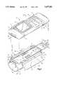
- the terminal 10includes a terminal housing 12 and an arm mounting assembly 14.
- the terminal housing 12is detached from the arm mounting assembly 14, while in FIG. 2, the housing 12 is attached to the arm mounting assembly 14.
- the terminal housing 12defines an interior region which supports circuitry of the terminal 10. Opposite ends 16, 18 of the terminal housing interchangeably accept one of a battery pack 20 and a dataform reader module 22.
- the battery pack 20is electrically coupled to terminal circuitry through suitable interface connectors (not shown) to supply power to the circuitry.
- the reader module 22is actuated to read a bar code dataform through a window 24 disposed at an end of the module.
- the window 24is "aimed" at a target dataform (not shown) and the reader module 22 is actuated to read the target dataform along the direction D (FIG. 1).
- the reader module 22may be a laser scanner, a charge coupled device (CCD) imaging reader or any other suitable dataform reading device.
- CCDcharge coupled device
- the reader module 22is electrically coupled to the terminal circuitry by suitable connectors (not shown) to receive power and to send a signal representative of a read dataform to bar code decoding circuitry disposed in the housing 12. Since the battery pack 20 and the reader module 22 are interchangeable with respect to the homing ends 16, 18, the reader module 22 may be suitably mounted on the terminal housing 12 such that the window 24, and, therefore, the dataform reading direction D, is away from the operator's body when the terminal 10 is attached to either an operator's right forearm (shown in dashed lines in FIG. 2) or left forearm (not shown) and the operator extends his or her arm toward the target dataform.
- the reader module 22includes two buttons 26 (best seen in FIG. 1A) which are simultaneously depressed to release the module from the terminal housing end 16 to which it is attached.
- the battery pack 20includes two buttons 28 (best seen in FIG. 1A) which are simultaneously depressed to release the battery pack from the terminal housing end 18.
- An upper surface 30 of the terminal housing 12supports a plurality of keys 32 which are used for inputting data and providing commands to the terminal circuitry, including initiating a bar code dataform reading session with the reader module 22.
- the terminal housing upper surface 30also supports a display 34 which is angled toward the operator's head (not shown) for better visibility.
- a rectangular shaped protruding portion or docking base 36is defined by extending portions from a lower surface 38 of the terminal housing 12, from a lower surface 40 of the battery pack 20 and from a lower surface 42 of the bar code dataform reader module 22.
- the protruding portion or docking base 36includes indentations 44 (better seen in section in FIG. 3) whose function will be discussed below.
- Input/output conductive contacts 46(one of which is also seen in FIG. 4A), which are flush with an outer surface of the protruding portion or docking base 36, are coupled to terminal electrical circuitry.
- the conductive contacts 46provide for connection of input signals, output signals, power for recharging cells in the battery pack 20, and ground connections to a peripheral device, e.g., a bar code printer or battery charger (not shown).
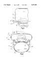
- the arm mounting assembly 14includes a docking member 50, a flexible sleeve 52 and a flexible strap 54.
- the sleeve 52is comprised of a resilient, durable rubber or other elastic material and provides a secure, non-slippery base for the docking member 50.
- the sleeve 52serves several purposes including providing a non-slippery base for the docking member 50, protecting the operator's arm from the docking member and protecting the terminal housing 12 from vibration which would otherwise be transferred from the operator to the terminal housing.
- the sleeve 52extends just shy of the operator's knuckles (shown in dashed lines in FIG. 2) and includes a thumb hole 56 which prevents the sleeve from rotating around the operator's forearm.
- the sleeve 52is approximately one-eight inch thick and is cylindrical in shape. It is made of a hypo-allergenic elastic material and is sized to fit snugly around an operator's forearm. In order to allow a secure fit, the sleeve 52 is tapered such that a first end 58 of the sleeve (toward the operator's knuckles) has a circumference which is smaller then an opposite end 59 toward the operator's elbow. The tapered sleeve 52 conforms to the shape of the operator's forearm.
- the docking member 50defines a recessed area into which the docking base 36 of the terminal housing 12 fits to secure the terminal housing to the docking member.
- the docking member 50is comprised of polypropolene providing rigidity and durability while also permitting a degree of flexibility. Of course, other materials having similar mechanical properties could also be used.
- the docking member 50includes a base 60, a perimeter wall 61 extending upwardly from the base, flexible securing flaps 62 and a primary release tab 63.
- the base 50has a low profile to minimize a distance it extends above the operator's forearm.
- the perimeter wall 61extends from the base 50 just less than 0.5 inches.
- the flexible securing flaps 62each have a thin, outwardly extending flex portion 64 and a thicker downwardly extending portion 66.
- the outwardly extending flex portion 64extends outwardly from the perimeter wall 61.
- the flex portions 64allow the docking station 50 to better accommodate attachment to a variety of different operator forearm sizes.
- each downwardly extending portion 66Secured to each downwardly extending portion 66 is a support rod 70.
- the support rod 70is comprised of stainless steel metal and each support rod has two hooked shaped ends 72 which are integrally molded into the downwardly extending portion 66. Each hooked shaped end 72 extends approximately one inch into the downwardly extending portion 645.
- the support rods 70rotate with respect to the docking member 50 to provide additional adjustability for different size forearms.
- the perimeter wall 61includes a front section 74, a back section 76 and two side sections 78.
- the perimeter wall 61 and the base 60form the recess which accepts the docking base 36 of the terminal housing 12.
- the front and back sections 74, 76each include an extending lip 80 adjacent an upper surface of each which interfits with the corresponding indentations 44 in the bar code dataform reader module 22 and the battery pack 20.
- the terminal housing docking base 36is aligned with the recess of the docking member 50 then the terminal housing and docking member are pressed together. As the terminal housing docking base 36 seats against the base 60 of the docking member 50, the extending lips 80 snap into respective indentations 44 to secure the terminal housing 12 to the docking member 50.
- the strength of the attachment between the terminal housing 12 and the docking member 50is further enhanced by frictional holding forces resulting from the snug line to line geometric fit between an outer periphery of the docking base 36 and an inner surface of the docking member perimeter wall 61.
- the strength of the attachment between the terminal homing 12 and the docking member 50is great enough to avoid accidental disengagement resulting from normal jarring and bumping that occur in the workplace. On the other hand; if a force sufficient to harm the operator's arm impacts the terminal housing 12, the strength of attachment is small enough to permit the terminal housing to release.
- the portable terminal 10includes having the lips 80 extending from the front and back sections 74, 76 of the perimeter wall 61, it should be appreciated that the perimeter wall could alternately be configured to have lips extending from the two side sections 78 or extending from one side section 78 and the front section 74, etc.
- the mating indentations 44would have to be appropriately relocated on the docking base 36 to be aligned with and receive the extending lips wherever they may be positioned.
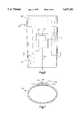
- the base 60 of the docking member 50is shaped to comfortably fit a curved shape of the operator's forearm. Particularly, the base 60 is curved along a longitudinal axis A--A (FIG. 1C) with a radius of curvature of six inches.
- the base 60 of the docking member 50includes eight electrical connector receiving slots 80, 81, 82, 83, 84, 85, 86, 87. Aligned with and located outwardly of the electrical connector receiving slots 80-87 are recesses 90-97. Extending along the upper surface of the base 60 adjacent the side wall sections 78 are two indentation channels. The channels 100, 102 terminate in openings 104, 106 in the back section 76 of the peripheral wall 61.
- FIG. 4Aprovides a cross sectional view of one of the electrical connector receiving slots 87 and the corresponding recess 97.
- eight conductors 110, 111, 112, 113, 114, 115, 116, 117 and eight conductive wires 120, 121, 122, 123, 124, 125, 126, 127, each of which is soldered to a corresponding one of the conductors,provide electrical coupling between the terminal housing conductors 46 of the terminal housing 12 and an external peripheral device (not shown).
- each of the conductors 110-117has a hook-shaped end 130 which hooks over a small cross member 132 of its corresponding connector receiving slot 80-87.
- each of the terminal housing conductors 46contacts a portion of the hook shaped distal end 130 of its respective aligned conductor 110-117.
- each of the conductors 110-117additionally includes a flat portion 134 at an end opposite the hook shaped end 130. The flat portion 134 of each conductor 110-117 fits into a corresponding recess 90-97.
- the four connectors 110, 111, 112, 113are used to handle a transmit, receive, ground and battery charging signals respectively.
- opposite cornered connectors 110-117are electrically coupled together, that is, connector 110 is electrically coupled to connector 114, connector 111 is electrically coupled to connector 115, connector 112 is electrically coupled to connector 116, and connector 113 is electrically coupled to connector 117.
- These opposite cornered couplingsare accomplished by connecting appropriate pairs of conductive wires in an external connector 140. That is, wires 120 and 124 are coupled electrically at the external connector 140 to couple connectors 110-114 (FIG. 1).
- Wires 121 and 125are electrically coupled at the external connector 140 to couple connectors 111, 115.
- Wires 122 and 126are electrically coupled at the external connector 140 to couple connectors 112, 116.
- wires 123 and 125are electrically coupled at the external connector 140 to couple connectors 113, 117.
- the wires 120-123are disposed in the indentation channel 100 and pass from the docking member 50 through the opening 104.
- the wires 124-127are disposed in the indentation channel 102 and pass from the docking member 50 through the opening 106.
- the strap 54secures the docking member 50 to the sleeve 52.
- the strap 54is approximately nine inches long and approximately five inches wide (just less than the width of the rods 70).
- the strap 54is attached at one end 150 to the sleeve 52 by sewing.
- two strips 152, 154 of VELCRO® hook and eye materialare affixed to the strap 54 to provide an adjustable fastening mechanism.
- the operatorinitially positions the sleeve 52 along his or her arm such that the tapered end 58 is closest to his or her knuckles. Further, the operator's thumb is inserted into the thumb slot 56. Next, the operator positions the docking member 50 onto the sleeve 52 such that the primary release tab 63 is pointing toward his or her knuckles. The primary release tab 63 is positioned in this direction to avoid inadvertent disengagement of the terminal housing 12 from the docking member 50 during arm movements. Such disengagement may occur if the primary release tab 63 is positioned toward the operator's elbow.
- the strap 54is looped around the support rod 70 and the two strips VELCRO® hook and eye material 152, 154 are pressed together to achieve a secure yet comfortable fit.
- the terminal housing 12is aligned with the docking member 50 such that the dataform reader module 22 is facing the operator's knuckles and the terminal housing docking base 36 is aligned with the recess of the docking member 50. Pressure is then applied to the terminal housing 12 to insert the docking base 36 into the terminal housing recess, as described earlier, thereby securing the terminal housing 12 to the arm mounting assembly 14.
- the primary release tab 63To disengage the terminal housing 12 from the docking member 50 the primary release tab 63 is grasped and pushed downwardly away from the terminal housing thereby disengaging the terminal housing from the docking member.
- the primary release tab 63has an angularly shaped distal portion 156 (FIG. 3) which facilitates grasping the primary release tab 63 when disengaging the terminal housing 12 from the docking member 50.
- FIG. 5An alternate embodiment of the portable data terminal of the present invention is shown generally at 10' in FIG. 5.
- the terminal 10'includes a terminal housing 12' and an arm mounting assembly 14'.
- the difference between the two terminal embodiments 10 and 10'is that in the second terminal embodiment 10', two straps 54a', 54b', each of which is affixed at one end by sewing to a sleeve 52', are utilized to secure the docking member 50' to the sleeve 52'.
- each strap 54a', 54b'has a VELCRO® hook and eye material strip 154a', 154b' affixed near an end of the strap opposite of the end affixed to the sleeve 52'.
- the VELCRO® hook and eye material strips 152a', 154a'are pressed together and the VELCRO® strips 152b', 154b' are pressed together to secure the docking member 50' to the sleeve 52'.
- FIGS. 6 and 7Yet another embodiment of an elastic sleeve of the portable data terminal 10' of the present invention is shown generally at 52" in FIGS. 6 and 7.
- the pouch 170is sewn to the sleeve 52 on three sides along a line 172 and is sized to receive a low profile battery pack 174 which is slid into the pouch's one open side.
- the open side of the pouch 170includes an elastic strip 176 which partially encloses the battery pack 174 to prevent the battery pack from falling out of the pouch during arm movement by the operator.
- a small hand held triggering device(not shown) which would be held in the operator's hand and electrically coupled to the connector 140.
- the operatorwould engage the trigger, for example, by depressing a trigger button, to actuate the bar code dataform reader module to commerce reading a dataform.
- the triggering devicewould be held in the hand corresponding the arm the terminal 10 is mounted on.
Landscapes
- Engineering & Computer Science (AREA)
- Theoretical Computer Science (AREA)
- Computer Hardware Design (AREA)
- Human Computer Interaction (AREA)
- Physics & Mathematics (AREA)
- General Engineering & Computer Science (AREA)
- General Physics & Mathematics (AREA)
- Casings For Electric Apparatus (AREA)
- Telephone Set Structure (AREA)
Abstract
Description
Claims (15)
Priority Applications (1)
| Application Number | Priority Date | Filing Date | Title |
|---|---|---|---|
| US08/554,076US5657201A (en) | 1995-11-06 | 1995-11-06 | Portable data collection terminal including arm mounting assembly |
Applications Claiming Priority (1)
| Application Number | Priority Date | Filing Date | Title |
|---|---|---|---|
| US08/554,076US5657201A (en) | 1995-11-06 | 1995-11-06 | Portable data collection terminal including arm mounting assembly |
Publications (1)
| Publication Number | Publication Date |
|---|---|
| US5657201Atrue US5657201A (en) | 1997-08-12 |
Family
ID=24211970
Family Applications (1)
| Application Number | Title | Priority Date | Filing Date |
|---|---|---|---|
| US08/554,076Expired - LifetimeUS5657201A (en) | 1995-11-06 | 1995-11-06 | Portable data collection terminal including arm mounting assembly |
Country Status (1)
| Country | Link |
|---|---|
| US (1) | US5657201A (en) |
Cited By (115)
| Publication number | Priority date | Publication date | Assignee | Title |
|---|---|---|---|---|
| US5808289A (en)* | 1996-09-30 | 1998-09-15 | Telxon Corporation | Arm mounted portable data collection device with rotatable and detachable dataform reader module |
| US5931764A (en)* | 1998-06-24 | 1999-08-03 | Viztec, Inc. | Wearable device with flexible display |
| WO1999047019A1 (en)* | 1998-03-16 | 1999-09-23 | Orang-Otang Computers, Inc. | Key palette improvements |
| US5969328A (en)* | 1995-11-17 | 1999-10-19 | Intermec Ip Corp | Portable hand-held data terminal having curvilinear housing and keypad |
| US5984188A (en)* | 1989-10-30 | 1999-11-16 | Symbol Technologies, Inc. | Terminal with board-mounted slim scan module |
| GB2341037A (en)* | 1998-11-23 | 2000-03-01 | Horst Spanyar | A wearable keypad for connection with a mobile phone |
| EP1022644A1 (en)* | 1999-01-25 | 2000-07-26 | Xybernaut Corporation | Flat panel display |
| US6097606A (en)* | 1998-05-28 | 2000-08-01 | International Verifact Inc. | Financial transaction terminal with limited access |
| US6109528A (en)* | 1995-12-22 | 2000-08-29 | Intermec Ip Corp. | Ergonomic hand-held data terminal and data collection system |
| WO2001007993A1 (en)* | 1999-07-26 | 2001-02-01 | Viztec, Inc. | Wearable device |
| US6184804B1 (en)* | 1996-01-26 | 2001-02-06 | Orang-Otang Computers, Inc. | Key palette |
| US6188572B1 (en) | 1998-10-13 | 2001-02-13 | Dell Usa, L.P. | Movable docking station electrical connector |
| US6330961B1 (en)* | 2000-04-15 | 2001-12-18 | Anita Arriola Borja | Forearm mounted storage pouch for securing articles and utilizing a personal communicator |
| US20020153414A1 (en)* | 1999-08-09 | 2002-10-24 | First Data Corporation | Systems and methods for performing transactions at a point-of-sale |
| US20020156683A1 (en)* | 1999-08-09 | 2002-10-24 | First Data Corporation | Systems and methods for utilizing a point-of-sale system |
| US20020166891A1 (en)* | 1999-08-09 | 2002-11-14 | First Data Corporation | Systems and methods for deploying a point-of sale device |
| US20030012000A1 (en)* | 2001-07-12 | 2003-01-16 | Yukitaka Shinoki | Portable information terminal |
| US20030019894A1 (en)* | 2000-02-18 | 2003-01-30 | Marcus Caldana | Device for the quick and easy use of a small size cellular telephone |
| US20030082993A1 (en)* | 2001-10-25 | 2003-05-01 | Peters William H. | Toy travel clock |
| US20030209604A1 (en)* | 1996-01-26 | 2003-11-13 | Harrison Shelton E. | Wearable computing system, method and device |
| US20030213822A1 (en)* | 2002-05-20 | 2003-11-20 | Lautner Robert Martin | Ergonomic input-device holder |
| US20030222135A1 (en)* | 1999-08-09 | 2003-12-04 | First Data Corporation | Systems and methods for configuring a point-of-sale system |
| US6661653B1 (en)* | 1999-07-21 | 2003-12-09 | Paul M. Holmen | Apparatus for data entry |
| US6688526B2 (en)* | 1988-05-11 | 2004-02-10 | Symbol Technologies, Inc. | Bar code reader with a clip for being worn and supported by a user |
| US20040039693A1 (en)* | 2002-06-11 | 2004-02-26 | First Data Corporation | Value processing network and methods |
| US6734842B2 (en)* | 2001-05-01 | 2004-05-11 | General Electric Company | Portable and wearable data entry apparatus |
| US6732934B2 (en)* | 2001-01-12 | 2004-05-11 | Symbol Technologies, Inc. | Escorted shopper system |
| US20040148203A1 (en)* | 2002-10-08 | 2004-07-29 | First Data Corporation | Systems and methods for verifying medical insurance coverage |
| US20050015280A1 (en)* | 2002-06-11 | 2005-01-20 | First Data Corporation | Health care eligibility verification and settlement systems and methods |
| US20050017077A1 (en)* | 2003-07-23 | 2005-01-27 | Sudhir Bhatia | Mobile terminal with ergonomic housing |
| US20050040194A1 (en)* | 2003-08-19 | 2005-02-24 | Frye Rebecca Rachael | Hands-free forearm carrier of articles |
| US20050137986A1 (en)* | 2003-12-17 | 2005-06-23 | First Data Corporation | Methods and systems for electromagnetic initiation of secure transactions |
| US20050261968A1 (en)* | 2004-05-04 | 2005-11-24 | First Data Corporation | System and method for conducting transactions with different forms of payment |
| US20050288964A1 (en)* | 1999-08-09 | 2005-12-29 | First Data Corporation | Health care eligibility verification and settlement systems and methods |
| US7077328B2 (en)* | 1998-07-31 | 2006-07-18 | Abbott Laboratories | Analyte test instrument system including data management system |
| US7096205B2 (en) | 2001-03-31 | 2006-08-22 | First Data Corporation | Systems and methods for enrolling consumers in goods and services |
| US7103577B2 (en) | 2001-03-31 | 2006-09-05 | First Data Corporation | Systems and methods for staging transactions, payments and collections |
| US7117183B2 (en) | 2001-03-31 | 2006-10-03 | First Data Coroporation | Airline ticket payment and reservation system and methods |
| US7130817B2 (en) | 2000-12-15 | 2006-10-31 | First Data Corporation | Electronic gift linking |
| US20060261155A1 (en)* | 1999-08-09 | 2006-11-23 | First Data Corporation | Point of sale payment terminal |
| US7140546B1 (en)* | 2002-12-12 | 2006-11-28 | Symbol Technologies, Inc. | Battery pack with integrated human interface devices |
| US7158955B2 (en) | 2001-03-31 | 2007-01-02 | First Data Corporation | Electronic identifier payment systems and methods |
| US7184989B2 (en) | 2001-03-31 | 2007-02-27 | First Data Corporation | Staged transactions systems and methods |
| US7219832B2 (en) | 2004-06-17 | 2007-05-22 | First Data Corporation | ATM machine and methods with currency conversion capabilities |
| US7229385B2 (en)* | 1998-06-24 | 2007-06-12 | Samsung Electronics Co., Ltd. | Wearable device |
| US20070141869A1 (en)* | 2003-08-21 | 2007-06-21 | Hill-Rom Services, Inc. | Plug and receptacle having wired and wireless coupling |
| US20070145149A1 (en)* | 2005-12-22 | 2007-06-28 | Carnevali Jeffrey D | Body strap mount |
| US20070178950A1 (en)* | 2006-01-19 | 2007-08-02 | International Business Machines Corporation | Wearable multimodal computing device with hands-free push to talk |
| US7266533B2 (en) | 2000-12-15 | 2007-09-04 | The Western Union Company | Electronic gift greeting |
| US20070208662A1 (en)* | 2006-02-10 | 2007-09-06 | The Western Union Company | Biometric based authorization systems for electronic fund transfers |
| US20080024961A1 (en)* | 2006-07-20 | 2008-01-31 | Anderson Robert C | Wearable electronic device with edge-mounted battery |
| US20080032638A1 (en)* | 2006-07-20 | 2008-02-07 | Anderson Robert C | Wearable communication device with contoured back |
| US20080078794A1 (en)* | 2006-09-29 | 2008-04-03 | Hand Held Products, Inc. | Electronic accessory carrier |
| US7392940B2 (en) | 2005-05-18 | 2008-07-01 | The Western Union Company | In-lane money transfer systems and methods |
| US7398252B2 (en) | 2000-07-11 | 2008-07-08 | First Data Corporation | Automated group payment |
| US20080195497A1 (en)* | 2004-11-08 | 2008-08-14 | First Data Corporation | Unit-Based Prepaid Presentation Instrument Accounts And Methods |
| EP1970794A1 (en) | 2007-03-15 | 2008-09-17 | Eurotech SPA | Wearable device |
| WO2008132517A1 (en)* | 2007-05-01 | 2008-11-06 | The Medical Phone Limited | Configurable electronic device |
| US20080289483A1 (en)* | 2006-01-27 | 2008-11-27 | University Of South Florida | Method of modifying the frequency response of a wooden article |
| US7463946B2 (en) | 2001-11-08 | 2008-12-09 | First Data Corporation | Mail handling equipment and methods |
| WO2009007316A1 (en)* | 2007-07-06 | 2009-01-15 | Eurotech Spa | Attachment device for a wearable electronic apparatus and wearable electronic apparatus comprising said attachment device |
| US20090032560A1 (en)* | 2007-07-30 | 2009-02-05 | Hewlett-Packard Development Company Lp | Hand mount |
| US20090104888A1 (en)* | 2007-10-17 | 2009-04-23 | First Data Corporation | Onetime Passwords For Mobile Wallets |
| US20090124381A1 (en)* | 2007-11-09 | 2009-05-14 | Quillen Iii Howard Ellis | Ultimate football joystick |
| WO2003088005A3 (en)* | 2002-04-03 | 2009-06-18 | First Data Corp | Systems and methods for performing transactions at a point-of-sale |
| USD597302S1 (en)* | 2008-02-02 | 2009-08-04 | Blackhawk Industries Product Group Unlimited Llc | Information tablet |
| US20090200371A1 (en)* | 2007-10-17 | 2009-08-13 | First Data Corporation | Onetime passwords for smart chip cards |
| US7587342B2 (en) | 2000-07-11 | 2009-09-08 | First Data Corporation | Method for requesting and receiving an online payment through a payment enabler system |
| US7596529B2 (en) | 2002-02-13 | 2009-09-29 | First Data Corporation | Buttons for person to person payments |
| US7606734B2 (en) | 2000-07-11 | 2009-10-20 | The Western Union Company | Wide area network person-to-person payment |
| US7613653B2 (en) | 1999-12-30 | 2009-11-03 | First Data Corporation | Money order debit from stored value fund |
| US7641109B2 (en) | 2005-05-18 | 2010-01-05 | The Western Union Company | Money transfer cards, systems and methods |
| US20100061191A1 (en)* | 2008-09-09 | 2010-03-11 | Mike Chen | Silent time reminding device |
| USD616439S1 (en)* | 2009-06-19 | 2010-05-25 | Smartmatic International Corporation | Smart biometric data capture sub-assembly |
| US7783571B2 (en) | 2007-05-31 | 2010-08-24 | First Data Corporation | ATM system for receiving cash deposits from non-networked clients |
| US20100268611A1 (en)* | 2009-04-21 | 2010-10-21 | First Data Corporation | Systems and methods for pre-paid futures procurement |
| US7917395B2 (en) | 2004-09-28 | 2011-03-29 | The Western Union Company | Wireless network access prepayment systems and methods |
| US7933835B2 (en) | 2007-01-17 | 2011-04-26 | The Western Union Company | Secure money transfer systems and methods using biometric keys associated therewith |
| US7932457B2 (en) | 2006-01-27 | 2011-04-26 | University Of South Florida | Accelerated aging process for acoustic stringed instruments |
| US20110218043A1 (en)* | 2007-11-09 | 2011-09-08 | Quillen Iii Howard Ellis | Sports video game controller |
| US20120063066A1 (en)* | 2010-09-14 | 2012-03-15 | Curtis Floit | Ergonomic accessory for use with a portable electronic device |
| US8140131B1 (en)* | 2008-06-16 | 2012-03-20 | Leo Green | Systems and methods for holding mobile electronic devices |
| US8150763B2 (en) | 2001-03-31 | 2012-04-03 | The Western Union Company | Systems and methods for staging transactions, payments and collections |
| US20120165645A1 (en)* | 2010-12-23 | 2012-06-28 | Zephyr Technology Corporation | System method and device for monitoring physiological parameters of a person |
| US8244632B2 (en) | 2001-10-26 | 2012-08-14 | First Data Corporation | Automated transfer with stored value |
| US8258973B2 (en) | 2005-02-11 | 2012-09-04 | Hill-Rom Services, Inc. | Transferable patient care equipment support |
| US8374962B2 (en) | 2001-10-26 | 2013-02-12 | First Data Corporation | Stored value payouts |
| US8504473B2 (en) | 2007-03-28 | 2013-08-06 | The Western Union Company | Money transfer system and messaging system |
| US8659650B2 (en) | 2009-06-19 | 2014-02-25 | Smartmatic International Corporation | Portable apparatus for biometric and biographic data collection, storage and delivery, and method therefor |
| US8662245B1 (en) | 2006-01-27 | 2014-03-04 | University Of South Florida | Frequency response treatment of wood paneling |
| US8672220B2 (en) | 2005-09-30 | 2014-03-18 | The Western Union Company | Money transfer system and method |
| US8801643B2 (en) | 2010-02-12 | 2014-08-12 | Covidien Lp | Compression garment assembly |
| US8818904B2 (en) | 2007-01-17 | 2014-08-26 | The Western Union Company | Generation systems and methods for transaction identifiers having biometric keys associated therewith |
| US20150001290A1 (en)* | 2013-07-01 | 2015-01-01 | Maria Tovar | Wristband for commercial transactions on mobile devices |
| GB2516263A (en)* | 2013-07-16 | 2015-01-21 | Laurence Hartgill | Point-of-sale system |
| US8960537B2 (en) | 2004-10-19 | 2015-02-24 | The Western Union Company | Money transfer systems and methods |
| WO2015100008A1 (en) | 2013-12-28 | 2015-07-02 | Intel Corporation | Clasp assembly and data interconnection for wearable computing devices |
| USD734563S1 (en)* | 2012-11-07 | 2015-07-14 | Isaac S. Daniel | Wristband with a display screen |
| US9144168B2 (en) | 2012-03-08 | 2015-09-22 | The United States Of America, As Represented By The Secretary Of The Air Force | Appendage-mounted display apparatus |
| US20150281417A1 (en)* | 2014-03-25 | 2015-10-01 | Boe Technology Group Co., Ltd. | Auxiliary Device for Mobile Terminal and Mobile Terminal Product |
| US20160106201A1 (en)* | 2014-10-17 | 2016-04-21 | Biowerx, LLC | Smartphone armlet |
| US20160174674A1 (en)* | 2014-12-18 | 2016-06-23 | Hand Held Products, Inc. | Wearable sled system for a mobile computer device |
| US20160180133A1 (en)* | 2014-12-22 | 2016-06-23 | Hand Held Products, Inc. | Conformable hand mount for a mobile scanner |
| US9433532B2 (en) | 2008-09-30 | 2016-09-06 | Covidien Lp | Tubeless compression device |
| US20170086569A1 (en)* | 2015-09-24 | 2017-03-30 | Griffin Technology, Llc | Arm band portable electronic device case |
| US9612578B2 (en)* | 2015-05-26 | 2017-04-04 | Acer Incorporated | Wearable electronic device |
| US9853759B1 (en) | 2001-03-31 | 2017-12-26 | First Data Corporation | Staged transaction system for mobile commerce |
| US20190196535A1 (en)* | 2017-12-21 | 2019-06-27 | Datalogic Usa Inc. | Low-profile wearable scanning device |
| US10395769B2 (en) | 2015-12-16 | 2019-08-27 | Hill-Rom Services, Inc. | Patient care devices with local indication of correspondence and power line interconnectivity |
| US10439322B1 (en)* | 2018-06-05 | 2019-10-08 | Te Connectivity Corporation | Connector system for a wearable article |
| US10806194B1 (en)* | 2020-01-31 | 2020-10-20 | Joshua Tyson | Beauty gloves |
| US10984673B2 (en)* | 2019-06-07 | 2021-04-20 | Weinraub Enterprises, Inc. | Training device for stringed instrument player |
| US20230291151A1 (en)* | 2020-08-31 | 2023-09-14 | Sony Interactive Entertainment Inc. | Supporting apparatus |
| US12186241B2 (en) | 2021-01-22 | 2025-01-07 | Hill-Rom Services, Inc. | Time-based wireless pairing between a medical device and a wall unit |
| US12279999B2 (en) | 2021-01-22 | 2025-04-22 | Hill-Rom Services, Inc. | Wireless configuration and authorization of a wall unit that pairs with a medical device |
Citations (13)
| Publication number | Priority date | Publication date | Assignee | Title |
|---|---|---|---|---|
| US4136805A (en)* | 1977-07-01 | 1979-01-30 | Alpha Nova Development Corp. | Wrist band holder for electronic calculator |
| US4766299A (en)* | 1986-03-28 | 1988-08-23 | Spectra-Physics, Inc. | Hand-mounted bar code reader |
| US4768648A (en)* | 1985-09-13 | 1988-09-06 | Glass Larry C | Calculator money clip |
| GB2218895A (en)* | 1988-05-25 | 1989-11-29 | Paolo Zoli | Bracelets |
| US5183193A (en)* | 1991-08-06 | 1993-02-02 | Bernie Brandell | Wrist mounted map holder apparatus |
| US5191197A (en)* | 1988-05-11 | 1993-03-02 | Symbol Technologies, Inc. | Arm mounted scanner actuatable by hand movement |
| US5250790A (en)* | 1988-05-11 | 1993-10-05 | Symbol Technologies, Inc. | Hand-mounted scanner with automatic manual initiation of reading indicia |
| US5272324A (en)* | 1990-08-10 | 1993-12-21 | Interlink Technologies, Inc. | Portable scanner system with transceiver for two-way radio frequency communication |
| US5305181A (en)* | 1989-05-15 | 1994-04-19 | Norand Corporation | Arm or wrist mounted terminal with a flexible housing |
| US5309328A (en)* | 1992-10-14 | 1994-05-03 | Lum James C P | Handsfree forearm strap for portable equipment |
| US5329106A (en)* | 1992-10-02 | 1994-07-12 | Psc, Inc. | Handle-less bar code scanning system |
| US5340972A (en)* | 1991-05-13 | 1994-08-23 | Symbol Technologies, Inc. | Hands-free bar code scanner with finger activated optical control |
| US5404001A (en)* | 1992-10-08 | 1995-04-04 | Bard; Simon | Fiber optic barcode reader |
- 1995
- 1995-11-06USUS08/554,076patent/US5657201A/ennot_activeExpired - Lifetime
Patent Citations (13)
| Publication number | Priority date | Publication date | Assignee | Title |
|---|---|---|---|---|
| US4136805A (en)* | 1977-07-01 | 1979-01-30 | Alpha Nova Development Corp. | Wrist band holder for electronic calculator |
| US4768648A (en)* | 1985-09-13 | 1988-09-06 | Glass Larry C | Calculator money clip |
| US4766299A (en)* | 1986-03-28 | 1988-08-23 | Spectra-Physics, Inc. | Hand-mounted bar code reader |
| US5191197A (en)* | 1988-05-11 | 1993-03-02 | Symbol Technologies, Inc. | Arm mounted scanner actuatable by hand movement |
| US5250790A (en)* | 1988-05-11 | 1993-10-05 | Symbol Technologies, Inc. | Hand-mounted scanner with automatic manual initiation of reading indicia |
| GB2218895A (en)* | 1988-05-25 | 1989-11-29 | Paolo Zoli | Bracelets |
| US5305181A (en)* | 1989-05-15 | 1994-04-19 | Norand Corporation | Arm or wrist mounted terminal with a flexible housing |
| US5272324A (en)* | 1990-08-10 | 1993-12-21 | Interlink Technologies, Inc. | Portable scanner system with transceiver for two-way radio frequency communication |
| US5340972A (en)* | 1991-05-13 | 1994-08-23 | Symbol Technologies, Inc. | Hands-free bar code scanner with finger activated optical control |
| US5183193A (en)* | 1991-08-06 | 1993-02-02 | Bernie Brandell | Wrist mounted map holder apparatus |
| US5329106A (en)* | 1992-10-02 | 1994-07-12 | Psc, Inc. | Handle-less bar code scanning system |
| US5404001A (en)* | 1992-10-08 | 1995-04-04 | Bard; Simon | Fiber optic barcode reader |
| US5309328A (en)* | 1992-10-14 | 1994-05-03 | Lum James C P | Handsfree forearm strap for portable equipment |
Cited By (200)
| Publication number | Priority date | Publication date | Assignee | Title |
|---|---|---|---|---|
| US6688526B2 (en)* | 1988-05-11 | 2004-02-10 | Symbol Technologies, Inc. | Bar code reader with a clip for being worn and supported by a user |
| US5984188A (en)* | 1989-10-30 | 1999-11-16 | Symbol Technologies, Inc. | Terminal with board-mounted slim scan module |
| US5969328A (en)* | 1995-11-17 | 1999-10-19 | Intermec Ip Corp | Portable hand-held data terminal having curvilinear housing and keypad |
| US6109528A (en)* | 1995-12-22 | 2000-08-29 | Intermec Ip Corp. | Ergonomic hand-held data terminal and data collection system |
| US6184804B1 (en)* | 1996-01-26 | 2001-02-06 | Orang-Otang Computers, Inc. | Key palette |
| US7470244B2 (en) | 1996-01-26 | 2008-12-30 | Harrison Jr Shelton E | Flexion-discouraging splint system, method and device |
| US20030209604A1 (en)* | 1996-01-26 | 2003-11-13 | Harrison Shelton E. | Wearable computing system, method and device |
| US6595424B1 (en) | 1996-01-26 | 2003-07-22 | Shelton E. Harrison | Key palette |
| US5808289A (en)* | 1996-09-30 | 1998-09-15 | Telxon Corporation | Arm mounted portable data collection device with rotatable and detachable dataform reader module |
| WO1999047019A1 (en)* | 1998-03-16 | 1999-09-23 | Orang-Otang Computers, Inc. | Key palette improvements |
| US6097606A (en)* | 1998-05-28 | 2000-08-01 | International Verifact Inc. | Financial transaction terminal with limited access |
| US7229385B2 (en)* | 1998-06-24 | 2007-06-12 | Samsung Electronics Co., Ltd. | Wearable device |
| US5931764A (en)* | 1998-06-24 | 1999-08-03 | Viztec, Inc. | Wearable device with flexible display |
| US7854684B1 (en) | 1998-06-24 | 2010-12-21 | Samsung Electronics Co., Ltd. | Wearable device |
| US7077328B2 (en)* | 1998-07-31 | 2006-07-18 | Abbott Laboratories | Analyte test instrument system including data management system |
| US6188572B1 (en) | 1998-10-13 | 2001-02-13 | Dell Usa, L.P. | Movable docking station electrical connector |
| US6155841A (en)* | 1998-11-23 | 2000-12-05 | Spanyar; Horst | Device for electrically connecting a mobile phone to a keyboard |
| GB2341037B (en)* | 1998-11-23 | 2000-07-26 | Horst Spanyar | Device for electrically connecting a mobile phone to a keyboard |
| GB2341037A (en)* | 1998-11-23 | 2000-03-01 | Horst Spanyar | A wearable keypad for connection with a mobile phone |
| EP1022644A1 (en)* | 1999-01-25 | 2000-07-26 | Xybernaut Corporation | Flat panel display |
| US6661653B1 (en)* | 1999-07-21 | 2003-12-09 | Paul M. Holmen | Apparatus for data entry |
| WO2001007993A1 (en)* | 1999-07-26 | 2001-02-01 | Viztec, Inc. | Wearable device |
| US20020166891A1 (en)* | 1999-08-09 | 2002-11-14 | First Data Corporation | Systems and methods for deploying a point-of sale device |
| US20020156683A1 (en)* | 1999-08-09 | 2002-10-24 | First Data Corporation | Systems and methods for utilizing a point-of-sale system |
| US20030222135A1 (en)* | 1999-08-09 | 2003-12-04 | First Data Corporation | Systems and methods for configuring a point-of-sale system |
| US20020153414A1 (en)* | 1999-08-09 | 2002-10-24 | First Data Corporation | Systems and methods for performing transactions at a point-of-sale |
| US20050288964A1 (en)* | 1999-08-09 | 2005-12-29 | First Data Corporation | Health care eligibility verification and settlement systems and methods |
| US7506809B2 (en) | 1999-08-09 | 2009-03-24 | First Data Corporation | Systems and methods for configuring a point-of-sale system |
| US7540410B2 (en) | 1999-08-09 | 2009-06-02 | First Data Corporation | Point of sale payment terminal |
| US8751250B2 (en) | 1999-08-09 | 2014-06-10 | First Data Corporation | Health care eligibility verification and settlement systems and methods |
| US7600673B2 (en) | 1999-08-09 | 2009-10-13 | First Data Corporation | Systems and methods for performing transactions at a point-of-sale |
| US20070029376A1 (en)* | 1999-08-09 | 2007-02-08 | First Data Corporation | Systems and methods for configuring a point-of-sale system |
| US6886742B2 (en) | 1999-08-09 | 2005-05-03 | First Data Corporation | Systems and methods for deploying a point-of sale device |
| US6827260B2 (en) | 1999-08-09 | 2004-12-07 | First Data Corporation | Systems and methods for utilizing a point-of-sale system |
| US20060261155A1 (en)* | 1999-08-09 | 2006-11-23 | First Data Corporation | Point of sale payment terminal |
| US7086584B2 (en) | 1999-08-09 | 2006-08-08 | First Data Corporation | Systems and methods for configuring a point-of-sale system |
| US7613653B2 (en) | 1999-12-30 | 2009-11-03 | First Data Corporation | Money order debit from stored value fund |
| US6796467B2 (en)* | 2000-02-18 | 2004-09-28 | Franco Caldana | Device for the quick and easy use of a small size cellular telephone |
| US20030019894A1 (en)* | 2000-02-18 | 2003-01-30 | Marcus Caldana | Device for the quick and easy use of a small size cellular telephone |
| US6330961B1 (en)* | 2000-04-15 | 2001-12-18 | Anita Arriola Borja | Forearm mounted storage pouch for securing articles and utilizing a personal communicator |
| US7587342B2 (en) | 2000-07-11 | 2009-09-08 | First Data Corporation | Method for requesting and receiving an online payment through a payment enabler system |
| US7610222B2 (en) | 2000-07-11 | 2009-10-27 | First Data Corporation | Method for providing a money transfer service through a payment enabler system |
| US8024229B2 (en) | 2000-07-11 | 2011-09-20 | The Western Union Company | Wide area network person-to-person payment |
| US7941346B2 (en) | 2000-07-11 | 2011-05-10 | The Western Union Company | Wide area network person-to-person payment |
| US7398252B2 (en) | 2000-07-11 | 2008-07-08 | First Data Corporation | Automated group payment |
| US7930216B2 (en) | 2000-07-11 | 2011-04-19 | The Western Union Company | Method for making an online payment through a payment enabler system |
| US10558957B2 (en) | 2000-07-11 | 2020-02-11 | The Western Union Company | Requestor-based funds transfer system and methods |
| US7606734B2 (en) | 2000-07-11 | 2009-10-20 | The Western Union Company | Wide area network person-to-person payment |
| US7937292B2 (en) | 2000-07-11 | 2011-05-03 | The Western Union Company | Wide area network person-to-person payment |
| US7941342B2 (en) | 2000-07-11 | 2011-05-10 | The Western Union Company | Wide area network person-to-person payment |
| US7266533B2 (en) | 2000-12-15 | 2007-09-04 | The Western Union Company | Electronic gift greeting |
| US7512552B2 (en) | 2000-12-15 | 2009-03-31 | The Western Union Company | Electronic gift linking |
| US7130817B2 (en) | 2000-12-15 | 2006-10-31 | First Data Corporation | Electronic gift linking |
| US7908179B2 (en) | 2000-12-15 | 2011-03-15 | The Western Union Company | Electronic gift linking |
| US6732934B2 (en)* | 2001-01-12 | 2004-05-11 | Symbol Technologies, Inc. | Escorted shopper system |
| US7107249B2 (en) | 2001-03-31 | 2006-09-12 | First Data Corporation | Electronic identifier payment systems and methods |
| US7103577B2 (en) | 2001-03-31 | 2006-09-05 | First Data Corporation | Systems and methods for staging transactions, payments and collections |
| US7158955B2 (en) | 2001-03-31 | 2007-01-02 | First Data Corporation | Electronic identifier payment systems and methods |
| US9129464B2 (en) | 2001-03-31 | 2015-09-08 | The Western Union Company | Staged transactions systems and methods |
| US8150763B2 (en) | 2001-03-31 | 2012-04-03 | The Western Union Company | Systems and methods for staging transactions, payments and collections |
| US7096205B2 (en) | 2001-03-31 | 2006-08-22 | First Data Corporation | Systems and methods for enrolling consumers in goods and services |
| US7184989B2 (en) | 2001-03-31 | 2007-02-27 | First Data Corporation | Staged transactions systems and methods |
| US8706640B2 (en) | 2001-03-31 | 2014-04-22 | The Western Union Company | Systems and methods for enrolling consumers in goods and services |
| US8515874B2 (en) | 2001-03-31 | 2013-08-20 | The Western Union Company | Airline ticket payment and reservation system and methods |
| US7117183B2 (en) | 2001-03-31 | 2006-10-03 | First Data Coroporation | Airline ticket payment and reservation system and methods |
| US7716128B2 (en) | 2001-03-31 | 2010-05-11 | The Western Union Company | Electronic indentifier payment systems and methods |
| US9853759B1 (en) | 2001-03-31 | 2017-12-26 | First Data Corporation | Staged transaction system for mobile commerce |
| US7165052B2 (en) | 2001-03-31 | 2007-01-16 | First Data Corporation | Payment service method and system |
| US6734842B2 (en)* | 2001-05-01 | 2004-05-11 | General Electric Company | Portable and wearable data entry apparatus |
| US20030012000A1 (en)* | 2001-07-12 | 2003-01-16 | Yukitaka Shinoki | Portable information terminal |
| US20030082993A1 (en)* | 2001-10-25 | 2003-05-01 | Peters William H. | Toy travel clock |
| US8244632B2 (en) | 2001-10-26 | 2012-08-14 | First Data Corporation | Automated transfer with stored value |
| US8374962B2 (en) | 2001-10-26 | 2013-02-12 | First Data Corporation | Stored value payouts |
| US7463946B2 (en) | 2001-11-08 | 2008-12-09 | First Data Corporation | Mail handling equipment and methods |
| US7596529B2 (en) | 2002-02-13 | 2009-09-29 | First Data Corporation | Buttons for person to person payments |
| WO2003088005A3 (en)* | 2002-04-03 | 2009-06-18 | First Data Corp | Systems and methods for performing transactions at a point-of-sale |
| US6726070B2 (en)* | 2002-05-20 | 2004-04-27 | Robert Lautner | Ergonomic input-device holder |
| US20030213822A1 (en)* | 2002-05-20 | 2003-11-20 | Lautner Robert Martin | Ergonomic input-device holder |
| US20050015280A1 (en)* | 2002-06-11 | 2005-01-20 | First Data Corporation | Health care eligibility verification and settlement systems and methods |
| US8086539B2 (en) | 2002-06-11 | 2011-12-27 | The Western Union Company | Value processing network and methods |
| US20040039693A1 (en)* | 2002-06-11 | 2004-02-26 | First Data Corporation | Value processing network and methods |
| US9898581B2 (en) | 2002-06-11 | 2018-02-20 | First Data Corporation | Health care eligibility verification and settlement systems and methods |
| US20040148203A1 (en)* | 2002-10-08 | 2004-07-29 | First Data Corporation | Systems and methods for verifying medical insurance coverage |
| US7140546B1 (en)* | 2002-12-12 | 2006-11-28 | Symbol Technologies, Inc. | Battery pack with integrated human interface devices |
| US20050017077A1 (en)* | 2003-07-23 | 2005-01-27 | Sudhir Bhatia | Mobile terminal with ergonomic housing |
| US20070108291A1 (en)* | 2003-07-23 | 2007-05-17 | Symbol Technologies, Inc. | Mobile terminal with ergonomic housing |
| US7416129B2 (en) | 2003-07-23 | 2008-08-26 | Symbol Technologies, Inc. | Mobile terminal with ergonomic housing |
| US7175094B2 (en) | 2003-07-23 | 2007-02-13 | Symbol Technologics, Inc. | Mobile terminal with handle that houses a stylus |
| US20070158429A1 (en)* | 2003-07-23 | 2007-07-12 | Symbol Technologies, Inc. | Mobile terminal with ergonomic housing |
| US7562824B2 (en) | 2003-07-23 | 2009-07-21 | Symbol Technologies, Inc | Mobile terminal with ergonomic housing |
| US7195169B2 (en)* | 2003-07-23 | 2007-03-27 | Symbol Technologies, Inc. | Mobile terminal with ergonomic housing |
| US20050040194A1 (en)* | 2003-08-19 | 2005-02-24 | Frye Rebecca Rachael | Hands-free forearm carrier of articles |
| US7048162B2 (en) | 2003-08-19 | 2006-05-23 | Rebecca Rachael Designs | Hands-free forearm carrier of articles |
| US9925104B2 (en) | 2003-08-21 | 2018-03-27 | Hill-Rom Services, Inc. | Hospital bed and room communication modules |
| US9572737B2 (en) | 2003-08-21 | 2017-02-21 | Hill-Rom Services, Inc. | Hospital bed having communication modules |
| US8727804B2 (en) | 2003-08-21 | 2014-05-20 | Hill-Rom Services, Inc. | Combined power and data cord and receptacle |
| US20070141869A1 (en)* | 2003-08-21 | 2007-06-21 | Hill-Rom Services, Inc. | Plug and receptacle having wired and wireless coupling |
| US7399205B2 (en)* | 2003-08-21 | 2008-07-15 | Hill-Rom Services, Inc. | Plug and receptacle having wired and wireless coupling |
| US9142923B2 (en) | 2003-08-21 | 2015-09-22 | Hill-Rom Services, Inc. | Hospital bed having wireless data and locating capability |
| US10206837B2 (en) | 2003-08-21 | 2019-02-19 | Hill-Rom Services, Inc. | Hospital bed and room communication modules |
| US20110210833A1 (en)* | 2003-08-21 | 2011-09-01 | Mcneely Craig A | Combined power and data cord and receptacle |
| US7831519B2 (en) | 2003-12-17 | 2010-11-09 | First Data Corporation | Methods and systems for electromagnetic initiation of secure transactions |
| US20050137986A1 (en)* | 2003-12-17 | 2005-06-23 | First Data Corporation | Methods and systems for electromagnetic initiation of secure transactions |
| US20070078781A1 (en)* | 2003-12-17 | 2007-04-05 | First Data Corporation | Information access control |
| US7707110B2 (en) | 2004-05-04 | 2010-04-27 | First Data Corporation | System and method for conducting transactions with different forms of payment |
| US20050261968A1 (en)* | 2004-05-04 | 2005-11-24 | First Data Corporation | System and method for conducting transactions with different forms of payment |
| US7458507B2 (en) | 2004-06-17 | 2008-12-02 | First Data Corporation | ATM machine and methods with currency conversion capabilities |
| US7219832B2 (en) | 2004-06-17 | 2007-05-22 | First Data Corporation | ATM machine and methods with currency conversion capabilities |
| US10296876B2 (en) | 2004-09-28 | 2019-05-21 | The Western Union Company | Wireless network access prepayment systems and methods |
| US7917395B2 (en) | 2004-09-28 | 2011-03-29 | The Western Union Company | Wireless network access prepayment systems and methods |
| US8960537B2 (en) | 2004-10-19 | 2015-02-24 | The Western Union Company | Money transfer systems and methods |
| US20080195497A1 (en)* | 2004-11-08 | 2008-08-14 | First Data Corporation | Unit-Based Prepaid Presentation Instrument Accounts And Methods |
| US7813982B2 (en) | 2004-11-08 | 2010-10-12 | First Data Corporation | Unit-based prepaid presentation instrument accounts and methods |
| US8258973B2 (en) | 2005-02-11 | 2012-09-04 | Hill-Rom Services, Inc. | Transferable patient care equipment support |
| US7641109B2 (en) | 2005-05-18 | 2010-01-05 | The Western Union Company | Money transfer cards, systems and methods |
| US7753267B2 (en) | 2005-05-18 | 2010-07-13 | The Western Union Company | In-lane money transfer systems and methods |
| US9384476B2 (en) | 2005-05-18 | 2016-07-05 | The Western Union Company | Money transfer system and method |
| US8851371B2 (en) | 2005-05-18 | 2014-10-07 | The Western Union Company | In-lane money transfer systems and methods |
| US7392940B2 (en) | 2005-05-18 | 2008-07-01 | The Western Union Company | In-lane money transfer systems and methods |
| US8672220B2 (en) | 2005-09-30 | 2014-03-18 | The Western Union Company | Money transfer system and method |
| US20070145149A1 (en)* | 2005-12-22 | 2007-06-28 | Carnevali Jeffrey D | Body strap mount |
| US7296752B2 (en)* | 2005-12-22 | 2007-11-20 | Carnevali Jeffrey D | Body strap mount |
| US20070178950A1 (en)* | 2006-01-19 | 2007-08-02 | International Business Machines Corporation | Wearable multimodal computing device with hands-free push to talk |
| US20080289483A1 (en)* | 2006-01-27 | 2008-11-27 | University Of South Florida | Method of modifying the frequency response of a wooden article |
| US7977555B2 (en) | 2006-01-27 | 2011-07-12 | University Of South Florida | Method of modifying the frequency response of a wooden article |
| US8662245B1 (en) | 2006-01-27 | 2014-03-04 | University Of South Florida | Frequency response treatment of wood paneling |
| US7932457B2 (en) | 2006-01-27 | 2011-04-26 | University Of South Florida | Accelerated aging process for acoustic stringed instruments |
| US9542684B2 (en) | 2006-02-10 | 2017-01-10 | The Western Union Company | Biometric based authorization systems for electronic fund transfers |
| US20070208662A1 (en)* | 2006-02-10 | 2007-09-06 | The Western Union Company | Biometric based authorization systems for electronic fund transfers |
| US8345931B2 (en) | 2006-02-10 | 2013-01-01 | The Western Union Company | Biometric based authorization systems for electronic fund transfers |
| US8837784B2 (en) | 2006-02-10 | 2014-09-16 | The Western Union Company | Biometric based authorization systems for electronic fund transfers |
| US7844310B2 (en)* | 2006-07-20 | 2010-11-30 | L3 Communications Corporation | Wearable communication device with contoured back |
| US20080032638A1 (en)* | 2006-07-20 | 2008-02-07 | Anderson Robert C | Wearable communication device with contoured back |
| US20080024961A1 (en)* | 2006-07-20 | 2008-01-31 | Anderson Robert C | Wearable electronic device with edge-mounted battery |
| US8240530B2 (en)* | 2006-09-29 | 2012-08-14 | Hand Held Products, Inc. | Electronic accessory carrier |
| US20080078794A1 (en)* | 2006-09-29 | 2008-04-03 | Hand Held Products, Inc. | Electronic accessory carrier |
| US9123044B2 (en) | 2007-01-17 | 2015-09-01 | The Western Union Company | Generation systems and methods for transaction identifiers having biometric keys associated therewith |
| US7933835B2 (en) | 2007-01-17 | 2011-04-26 | The Western Union Company | Secure money transfer systems and methods using biometric keys associated therewith |
| US8818904B2 (en) | 2007-01-17 | 2014-08-26 | The Western Union Company | Generation systems and methods for transaction identifiers having biometric keys associated therewith |
| EP1970794A1 (en) | 2007-03-15 | 2008-09-17 | Eurotech SPA | Wearable device |
| US20080223890A1 (en)* | 2007-03-15 | 2008-09-18 | Eurotech Spa | Wearable device |
| US8504473B2 (en) | 2007-03-28 | 2013-08-06 | The Western Union Company | Money transfer system and messaging system |
| US10311410B2 (en) | 2007-03-28 | 2019-06-04 | The Western Union Company | Money transfer system and messaging system |
| US8762267B2 (en) | 2007-03-28 | 2014-06-24 | The Western Union Company | Money transfer system and messaging system |
| WO2008132517A1 (en)* | 2007-05-01 | 2008-11-06 | The Medical Phone Limited | Configurable electronic device |
| US20100188806A1 (en)* | 2007-05-01 | 2010-07-29 | Andrew Mulford | Configurable electronic device |
| US7783571B2 (en) | 2007-05-31 | 2010-08-24 | First Data Corporation | ATM system for receiving cash deposits from non-networked clients |
| WO2009007316A1 (en)* | 2007-07-06 | 2009-01-15 | Eurotech Spa | Attachment device for a wearable electronic apparatus and wearable electronic apparatus comprising said attachment device |
| US20100176166A1 (en)* | 2007-07-06 | 2010-07-15 | Eurotech Spa | Attachment device for a wearable electronic apparatus and wearable electronic apparatus comprising said attachment device |
| US9521886B2 (en) | 2007-07-06 | 2016-12-20 | Eurotech Spa | Attachment device for a wearable electronic apparatus and wearable electronic apparatus comprising said attachment device |
| US20090032560A1 (en)* | 2007-07-30 | 2009-02-05 | Hewlett-Packard Development Company Lp | Hand mount |
| US8196787B2 (en)* | 2007-07-30 | 2012-06-12 | Hewlett-Packard Development Company, L.P. | Hand mount |
| US8565723B2 (en) | 2007-10-17 | 2013-10-22 | First Data Corporation | Onetime passwords for mobile wallets |
| US8095113B2 (en) | 2007-10-17 | 2012-01-10 | First Data Corporation | Onetime passwords for smart chip cards |
| US20090104888A1 (en)* | 2007-10-17 | 2009-04-23 | First Data Corporation | Onetime Passwords For Mobile Wallets |
| US20090200371A1 (en)* | 2007-10-17 | 2009-08-13 | First Data Corporation | Onetime passwords for smart chip cards |
| US20090124381A1 (en)* | 2007-11-09 | 2009-05-14 | Quillen Iii Howard Ellis | Ultimate football joystick |
| US20110218043A1 (en)* | 2007-11-09 | 2011-09-08 | Quillen Iii Howard Ellis | Sports video game controller |
| USD597302S1 (en)* | 2008-02-02 | 2009-08-04 | Blackhawk Industries Product Group Unlimited Llc | Information tablet |
| US8140131B1 (en)* | 2008-06-16 | 2012-03-20 | Leo Green | Systems and methods for holding mobile electronic devices |
| US20100061191A1 (en)* | 2008-09-09 | 2010-03-11 | Mike Chen | Silent time reminding device |
| US9433532B2 (en) | 2008-09-30 | 2016-09-06 | Covidien Lp | Tubeless compression device |
| US8346611B2 (en) | 2009-04-21 | 2013-01-01 | First Data Corporation | Systems and methods for pre-paid futures procurement |
| US20100268611A1 (en)* | 2009-04-21 | 2010-10-21 | First Data Corporation | Systems and methods for pre-paid futures procurement |
| USD616439S1 (en)* | 2009-06-19 | 2010-05-25 | Smartmatic International Corporation | Smart biometric data capture sub-assembly |
| US8659650B2 (en) | 2009-06-19 | 2014-02-25 | Smartmatic International Corporation | Portable apparatus for biometric and biographic data collection, storage and delivery, and method therefor |
| US8801643B2 (en) | 2010-02-12 | 2014-08-12 | Covidien Lp | Compression garment assembly |
| US20120063066A1 (en)* | 2010-09-14 | 2012-03-15 | Curtis Floit | Ergonomic accessory for use with a portable electronic device |
| US9775561B2 (en)* | 2010-12-23 | 2017-10-03 | Covidien Lp | System method and device for monitoring physiological parameters of a person |
| US20120165645A1 (en)* | 2010-12-23 | 2012-06-28 | Zephyr Technology Corporation | System method and device for monitoring physiological parameters of a person |
| US9144168B2 (en) | 2012-03-08 | 2015-09-22 | The United States Of America, As Represented By The Secretary Of The Air Force | Appendage-mounted display apparatus |
| USD734563S1 (en)* | 2012-11-07 | 2015-07-14 | Isaac S. Daniel | Wristband with a display screen |
| US20150001290A1 (en)* | 2013-07-01 | 2015-01-01 | Maria Tovar | Wristband for commercial transactions on mobile devices |
| US8955745B2 (en)* | 2013-07-01 | 2015-02-17 | Maria Tovar | Wristband for commercial transactions on mobile devices |
| GB2516263A (en)* | 2013-07-16 | 2015-01-21 | Laurence Hartgill | Point-of-sale system |
| EP3087428A4 (en)* | 2013-12-28 | 2017-08-16 | Intel Corporation | Clasp assembly and data interconnection for wearable computing devices |
| WO2015100008A1 (en) | 2013-12-28 | 2015-07-02 | Intel Corporation | Clasp assembly and data interconnection for wearable computing devices |
| US20150281417A1 (en)* | 2014-03-25 | 2015-10-01 | Boe Technology Group Co., Ltd. | Auxiliary Device for Mobile Terminal and Mobile Terminal Product |
| US20160106201A1 (en)* | 2014-10-17 | 2016-04-21 | Biowerx, LLC | Smartphone armlet |
| US10136715B2 (en) | 2014-12-18 | 2018-11-27 | Hand Held Products, Inc. | Wearable sled system for a mobile computer device |
| US20160174674A1 (en)* | 2014-12-18 | 2016-06-23 | Hand Held Products, Inc. | Wearable sled system for a mobile computer device |
| US9743731B2 (en)* | 2014-12-18 | 2017-08-29 | Hand Held Products, Inc. | Wearable sled system for a mobile computer device |
| US20160180133A1 (en)* | 2014-12-22 | 2016-06-23 | Hand Held Products, Inc. | Conformable hand mount for a mobile scanner |
| US9727769B2 (en)* | 2014-12-22 | 2017-08-08 | Hand Held Products, Inc. | Conformable hand mount for a mobile scanner |
| US9612578B2 (en)* | 2015-05-26 | 2017-04-04 | Acer Incorporated | Wearable electronic device |
| US9955775B2 (en)* | 2015-09-24 | 2018-05-01 | Griffin Technology, Llc | Arm band case for portable electronic device |
| US10264873B2 (en)* | 2015-09-24 | 2019-04-23 | Griffin Technology, Llc | Arm band case for portable electronic device |
| US20170086569A1 (en)* | 2015-09-24 | 2017-03-30 | Griffin Technology, Llc | Arm band portable electronic device case |
| US9743743B2 (en)* | 2015-09-24 | 2017-08-29 | Griffin Technology, Llc | Arm band portable electronic device case |
| US10395769B2 (en) | 2015-12-16 | 2019-08-27 | Hill-Rom Services, Inc. | Patient care devices with local indication of correspondence and power line interconnectivity |
| US11188122B2 (en)* | 2017-12-21 | 2021-11-30 | Datalogic Usa Inc. | Low-profile wearable scanning device |
| US20190196535A1 (en)* | 2017-12-21 | 2019-06-27 | Datalogic Usa Inc. | Low-profile wearable scanning device |
| US10439322B1 (en)* | 2018-06-05 | 2019-10-08 | Te Connectivity Corporation | Connector system for a wearable article |
| EP3579352B1 (en)* | 2018-06-05 | 2021-01-06 | TE Connectivity Corporation | Connector system for a wearable article |
| US10984673B2 (en)* | 2019-06-07 | 2021-04-20 | Weinraub Enterprises, Inc. | Training device for stringed instrument player |
| US10806194B1 (en)* | 2020-01-31 | 2020-10-20 | Joshua Tyson | Beauty gloves |
| US20230291151A1 (en)* | 2020-08-31 | 2023-09-14 | Sony Interactive Entertainment Inc. | Supporting apparatus |
| US12300934B2 (en)* | 2020-08-31 | 2025-05-13 | Sony Interactive Entertainment Inc. | Supporting apparatus |
| US12186241B2 (en) | 2021-01-22 | 2025-01-07 | Hill-Rom Services, Inc. | Time-based wireless pairing between a medical device and a wall unit |
| US12279999B2 (en) | 2021-01-22 | 2025-04-22 | Hill-Rom Services, Inc. | Wireless configuration and authorization of a wall unit that pairs with a medical device |
Similar Documents
| Publication | Publication Date | Title |
|---|---|---|
| US5657201A (en) | Portable data collection terminal including arm mounting assembly | |
| US5808289A (en) | Arm mounted portable data collection device with rotatable and detachable dataform reader module | |
| US5305181A (en) | Arm or wrist mounted terminal with a flexible housing | |
| US6036093A (en) | Modular scanner with hand-held data terminal | |
| US5587577A (en) | Modular scanner with hand-held data terminal | |
| US5272324A (en) | Portable scanner system with transceiver for two-way radio frequency communication | |
| US6030290A (en) | Momentary contact motion switch for video games | |
| EP2059863B1 (en) | Wearable mobile computing system | |
| JP4729233B2 (en) | Adapter unit with handle grip for digital personal secretary | |
| US5850613A (en) | Apparatus and method for hands-free operation of a radio microphone | |
| JPH0916316A (en) | Portable transaction terminal for optical data entry and key entry without the use of a keyboard and hand-driven scanning device | |
| US7379052B1 (en) | Hand-held computer control device | |
| US20030038783A1 (en) | Wearable ergonomic computer mouse | |
| US6647248B1 (en) | Cradle | |
| US5479001A (en) | Right- and left-handed operable, grip-held pen computing device with removable data entry modules | |
| US5398855A (en) | Pager carrying device | |
| CA2190572A1 (en) | Battery latch for a communication device | |
| EP3960020B1 (en) | Watchband and watch case; and watch | |
| US5925873A (en) | Grip held and grip operable data entry device | |
| EP0373935A3 (en) | Hand-held bar code reader | |
| US20200237032A1 (en) | Apparatus for mounting on hand with identification device arranged on the apparatus, and method for manufacturing the apparatus | |
| CA2108138A1 (en) | A power tool having selectable inlet location | |
| KR102690697B1 (en) | Wearble robot and control method thereof | |
| KR102409788B1 (en) | Wearable Mobile Device System | |
| US6021310A (en) | Computer pager device |
Legal Events
| Date | Code | Title | Description |
|---|---|---|---|
| AS | Assignment | Owner name:TELETRANSACTIONS, INC., OHIO Free format text:ASSIGNMENT OF ASSIGNORS INTEREST;ASSIGNOR:KOCHIS, GARY;REEL/FRAME:007843/0877 Effective date:19960129 | |
| STCF | Information on status: patent grant | Free format text:PATENTED CASE | |
| AS | Assignment | Owner name:TELXON CORPORATION, OHIO Free format text:ASSIGNMENT OF ASSIGNORS INTEREST;ASSIGNOR:TELETRANSACTIONS, INC.;REEL/FRAME:009781/0759 Effective date:19990201 | |
| AS | Assignment | Owner name:BANK OF NEW YORK, THE, NEW YORK Free format text:SECURITY INTEREST;ASSIGNOR:TELXON CORPORATION;REEL/FRAME:009817/0901 Effective date:19990326 | |
| AS | Assignment | Owner name:BANK ONE, NA, OHIO Free format text:ASSIGNMENT OF ASSIGNORS INTEREST;ASSIGNOR:TELXON CORPORATION, A DELAWARE CORPORATION;REEL/FRAME:009866/0723 Effective date:19990326 | |
| AS | Assignment | Owner name:FOOTHILL CAPITAL CORPORATION AS AGENT, CALIFORNIA Free format text:SECURITY INTEREST;ASSIGNOR:TELXON CORPORATION;REEL/FRAME:010216/0081 Effective date:19990826 Owner name:TELXON CORPORATION, OHIO Free format text:RELEASE BY SECURED PARTY;ASSIGNOR:THE BANK OF NEW YORK, AS AGENT;REEL/FRAME:010216/0776 Effective date:19990830 Owner name:TELXON CORPORATION, OHIO Free format text:RELEASE OF SECURITY INTEREST;ASSIGNOR:BANK ONE, NA;REEL/FRAME:010216/0050 Effective date:19990830 | |
| FPAY | Fee payment | Year of fee payment:4 | |
| AS | Assignment | Owner name:SYMBOL TECHNOLOGIES, INC., NEW YORK Free format text:ASSIGNMENT OF ASSIGNORS INTEREST;ASSIGNOR:TELXON CORPORATION;REEL/FRAME:012795/0070 Effective date:20020327 | |
| AS | Assignment | Owner name:JPMORGAN CHASE BANK, N.A., NEW YORK Free format text:SECURITY INTEREST;ASSIGNOR:SYMBOL TECHNOLOGIES, INC.;REEL/FRAME:016116/0203 Effective date:20041229 | |
| FPAY | Fee payment | Year of fee payment:8 | |
| AS | Assignment | Owner name:TELXON CORPORATION, OHIO Free format text:RELEASE OF SECURITY AGREEMENT;ASSIGNOR:WELLS FARGO FOOTHILL, INC. (FORMERLY FOOTHILL CAPITAL CORPORATION);REEL/FRAME:016621/0303 Effective date:20050716 | |
| FPAY | Fee payment | Year of fee payment:12 | |
| AS | Assignment | Owner name:SYMBOL TECHNOLOGIES, INC., NEW YORK Free format text:RELEASE BY SECURED PARTY;ASSIGNOR:JPMORGANCHASE BANK, N.A.;REEL/FRAME:025441/0228 Effective date:20060901 | |
| AS | Assignment | Owner name:MORGAN STANLEY SENIOR FUNDING, INC. AS THE COLLATERAL AGENT, MARYLAND Free format text:SECURITY AGREEMENT;ASSIGNORS:ZIH CORP.;LASER BAND, LLC;ZEBRA ENTERPRISE SOLUTIONS CORP.;AND OTHERS;REEL/FRAME:034114/0270 Effective date:20141027 Owner name:MORGAN STANLEY SENIOR FUNDING, INC. AS THE COLLATE Free format text:SECURITY AGREEMENT;ASSIGNORS:ZIH CORP.;LASER BAND, LLC;ZEBRA ENTERPRISE SOLUTIONS CORP.;AND OTHERS;REEL/FRAME:034114/0270 Effective date:20141027 | |
| AS | Assignment | Owner name:SYMBOL TECHNOLOGIES, LLC, NEW YORK Free format text:CHANGE OF NAME;ASSIGNOR:SYMBOL TECHNOLOGIES, INC.;REEL/FRAME:036083/0640 Effective date:20150410 | |
| AS | Assignment | Owner name:SYMBOL TECHNOLOGIES, INC., NEW YORK Free format text:RELEASE BY SECURED PARTY;ASSIGNOR:MORGAN STANLEY SENIOR FUNDING, INC.;REEL/FRAME:036371/0738 Effective date:20150721 |