US5657032A - Aircraft cellular communications antenna - Google Patents
Aircraft cellular communications antennaDownload PDFInfo
- Publication number
- US5657032A US5657032AUS08/518,794US51879495AUS5657032AUS 5657032 AUS5657032 AUS 5657032AUS 51879495 AUS51879495 AUS 51879495AUS 5657032 AUS5657032 AUS 5657032A
- Authority
- US
- United States
- Prior art keywords
- port
- antenna
- longitudinal axis
- radiating element
- cylinder
- Prior art date
- Legal status (The legal status is an assumption and is not a legal conclusion. Google has not performed a legal analysis and makes no representation as to the accuracy of the status listed.)
- Expired - Lifetime
Links
Images
Classifications
- H—ELECTRICITY
- H01—ELECTRIC ELEMENTS
- H01Q—ANTENNAS, i.e. RADIO AERIALS
- H01Q13/00—Waveguide horns or mouths; Slot antennas; Leaky-waveguide antennas; Equivalent structures causing radiation along the transmission path of a guided wave
- H01Q13/10—Resonant slot antennas
- H—ELECTRICITY
- H01—ELECTRIC ELEMENTS
- H01Q—ANTENNAS, i.e. RADIO AERIALS
- H01Q1/00—Details of, or arrangements associated with, antennas
- H01Q1/27—Adaptation for use in or on movable bodies
- H01Q1/28—Adaptation for use in or on aircraft, missiles, satellites, or balloons
- H01Q1/282—Modifying the aerodynamic properties of the vehicle, e.g. projecting type aerials
- H01Q1/283—Blade, stub antennas
Definitions
- the present inventionrelates to a communications antenna and, in particular, to an aircraft communications antenna for receiving and transmitting horizontal polarized electromagnetic signals in cellular communications.
- antennasemit and/or receive communication signals propagating through air and space. Numerous different types of communications antennas are in use today. Antennas transmit (and receive) electromagnetic waves made of a combination of electric and magnetic fields propagating in a certain direction. The electric and magnetic fields are perpendicular to each other and are perpendicular to the direction of propagation of the electromagnetic wave (EM wave).
- EM waveelectromagnetic wave
- the orientation of the electric and magnetic fields with respect to the surface of the earthdetermines whether the electromagnetic wave (the communication signal) is vertically or horizontally polarized. If the electric field is parallel to the earth, the EM wave is horizontally polarized. If the electric field is perpendicular to the earth, the EM wave is vertically polarized.
- the structure and orientation of an antennadictates whether the antenna emits or receives vertically or horizontally polarized EM waves (some structures emit and/or receive circularly polarized EM waves, however circular polarization will not be discussed herein). Generally, both the transmit and receive antennas in a communications system must be of the same polarization for proper transmission and reception.
- Antennasradiate and receive energy in many different directions, however, most antennas radiate or receive energy in a very specific geometric radiation pattern that is non-uniform over a 360 degree circle parallel to the earth's surface. Antennas exhibiting this characteristic are called directional antennas. Some antennas are constructed (or oriented) to radiate or receive energy in all directions parallel to the surface of the earth. These antennas are called omni-directional antennas.
- a half-wave dipole antennahas a radiation pattern in the shape of a doughnut. Most of the energy radiated from a half-wave dipole is radiated substantially from right angles to the length of the dipole. As such, almost no energy is radiated along the lines extending along the length of the dipole.
- a half-wave dipole mounted horizontally to the earthis a directional antenna (i.e. minimal radiation in the directions along the length of the dipole).
- a half-wave dipole mounted vertically to the earththerefore, is an omni-directional antenna (i.e. equal amount of radiation in all directions parallel to the earth).
- a dipole antennaIn the transmission mode, a dipole antenna should be pointed broadside to the desired direction of transmission or, in the reception mode, pointed broadside to the point of transmission of the signal from a transmitter.
- Standard ground mobile cellular communications systemsuse vertically polarized signals in the 800-900 MHz range.
- aircraft cellular communications systemuse horizontally polarized signals to prevent interference with the vertically polarized ground mobile cellular communication systems. While RF power management control techniques may help reduce some of this interference, a substantial amount of interference is still present.
- the design of the aircraft antenna(coupled with the attributes of the operating environment, i.e., air-to-ground communication from a moving aircraft) plays a critical role in the performance of the aircraft cellular communications system. It must provide a high rejection of the vertically polarized ground communications signals.
- One type of antenna that may be used in an aircraft cellular communications systemis a stacked horizontal dipole antenna. It provides near omni-directional patterns with horizontal polarization. This type of antenna is usually oriented lengthwise along the centerline of the aircraft, and for that reason, an undesirable null in the antenna pattern exists along the axis of the antenna, fore and aft of the aircraft. Loss of the communication link is possible if the aircraft is turning or maintains an inbound/outbound flight profile with the ground station. Further, radiation of a vertical polarized component also increases for increasing angles off antenna boresight and the amount of horizontal component to vertical component suppression degrades overall performance. Consequently, use of a stacked horizontal dipole antenna results in a high potential for interference and/or loss of communications.
- an antennafor use with aircraft cellular communication systems that transmits and receives horizontally polarized signals and provides high rejection of the vertically polarized ground mobile cellular communications signals. Further, the antenna should be capable of minimizing any potential for interference with ground mobile and fixed cell sites and reducing susceptibility to interference from sites that transmit vertical polarized signals. Also needed is an antenna that provides a deep null in the radiation pattern to prevent interference from ground mobile and fixed cell sites positioned substantially directly below the aircraft in flight. Additionally, there is needed an omni-directional antenna to provide maximum radiation outward to the horizon so that the communications link is independent of aircraft flight profile and ground station location.
- an antenna radiating elementincluding an elliptic-shaped cylinder having a first port disposed in a first side and a second port disposed in a second side.
- a microstrip feed network located within the radiating elementradiates and receives horizontal polarized electromagnetic signals through the first port and the second port whereby the antenna radiating element radiates and receives electromagnetic signals substantially omnidirectionally.
- an antenna systemincluding an antenna radiating element and a radome mounted on the underside of an aircraft.
- the antenna radiating elementhas an elliptic, cylindrical shape including a first slot disposed in a first side for passing electromagnetic signals and a second slot disposed in a second side for passing electromagnetic signals.
- a feed networktransmits and receives horizontal polarized electromagnetic signals through the first slot and the second slot whereby the antenna radiating element radiates and receives electromagnetic signals substantially omnidirectionally.
- the radomesubstantially surrounds or encompasses the antenna radiating element.
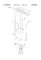
- FIG. 1is an elevated view illustrating an antenna radiating element in accordance with the present invention
- FIG. 2illustrates a microstrip feed network used with the present invention
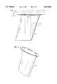
- FIG. 3is a side view illustrating an antenna system including the antenna radiating element of FIG. 1 within a radome;
- FIG. 4is an elevated view illustrating the radome shown in FIG. 3.
- the antenna radiating element 10includes an elliptic-shaped cylinder 12 having a first side 14 and a second side 16. While the cylinder may include many cylindrical shapes, in the preferred embodiment the cylinder 12 is elliptic-shaped. The first side 14 and the second side 16 have curved surfaces and are connected to form the elliptical cylinder 12 defining a radiation cavity 22. As will be appreciated, the first side 14 and the second side 16 may be manufactured or connected integrally to form the cylinder 12.
- the height H of the antenna radiating elementis approximately ten (10) inches, the length L is approximately four and one-quarter (41/4) inches, and the width W is approximately one (1) inch.
- the first side 14has a first port 18 for receiving RF signals into the radiation cavity 22 and for transmitting RF signals from the radiation cavity 22.
- the second side 16includes a second port 20 (shown in dotted lines) similar to the port 18.
- the ports (or apertures) 18, 20are oriented substantially vertically along the first side 14 and the second side 16, respectively.
- the ports 18, 20are in the shape of rectangular slots with a length of approximately 83/4 inches and a width of approximately 1/2 inch.
- the longitudinal axis of each port 18, 20is substantially parallel to the longitudinal axis of the elliptic-shaped cylinder.
- the configuration of the ports 18, 20 in the cylinder 12substantially rejects and/or suppresses vertically polarized electromagnetic signals.
- a microstrip feed network 24Disposed within the radiation cavity 22 is a microstrip feed network 24.
- the microstrip feed network 24is connected or coupled to the port 18 by connection to two feed tabs 25.
- the microstrip feed network 24is connected or coupled to the port 20 by connection to two feeds tabs 27.
- the feed tabs 25, 27are formed as part of the ports 18, 20, respectively.
- the microstrip feed networkis constructed on a small circuit card assembly that is placed between the ports 18 and 20 within the radiation cavity 22.
- the feed tabs 25, 27are each then connected preferably by soldering, to a point on the microstrip feed network 24 to provide a feed path to the ports 18, 20.
- the microstrip feed network 24transmits and/or receives RF signals through the ports 18, 20.
- the microstrip feed networkincludes a first feed point for transmitting and/or receiving RF signals through the first port 18 and a second feed point for transmitting and/or receiving RF signals through the second port 20.
- the first feed point and the second feed pointare positioned on the microstrip network 24 such that the RF signal transmitted and/or received from the first feed point is substantially 180 degrees out of phase with the RF signal transmitted and/or received from the second feed point.
- the RF signals transmitted and receivedare in the range of 800-900 MHz.
- the microstrip feed network 24radiates or emits two orthogonal electromagnetic signals substantially 180 degrees out of phase with each other from the first port and the second port. It will be understood, the microstrip feed network 24 generally receives electromagnetic signals through the first port 18 and also receives electromagnetic signals through the second port 20. The feed points are positioned within the microstrip feed network such that the RF signals received through one of the ports 18, 20 is shifted substantially 180 degrees out of phase. As such, the RF signals received are then combined to produce the received RF signal that is coupled a receiver (not shown) in a conventional communication system.
- the microstrip feed network 24is positioned within the radiation cavity 22 of the antenna radiation element 10 and emits (or radiates) and receives RF signals.
- the microstrip feed network 24provides a signal path to a receiver (not shown) and from a transmitter (not shown) in an aircraft cellular conventional communication system.
- any radiation or reception sourcemay be used within the radiation cavity 22 to obtain the desired results, such as stripline feed network, coax feed network, and the like.
- the network 24is a microstrip feed network.
- the geometry and structure of the antenna radiating element 10 and the ports 18, 20provide an antenna that transmits and receives horizontally polarized RF signals and rejects vertically polarized RF signals.
- the antenna radiating element 10provides a greater than 20 dB nominal suppression of vertically polarized signals.
- the curved nature of the ports 18, 20 within the curved first side 14 and the curved second side 16provide omni-directional transmission and reception of RF signals.
- the antenna radiating elementallows the aircraft to attain almost any relatively horizontal flight profile without affecting the communications link between the aircraft and a ground station. An aircraft having such an antenna can make turns and/or maintain an inbound/outbound flight profile with respect to the location of the ground station without loss or potential loss of the communications link.
- the antenna system 40includes the antenna radiating element 10 having an elliptic-shaped cylinder 12 and ports or slots 18, 20, all shown in dotted lines.
- the antenna system 40further include a radome 42 that substantially encompasses or surrounds the antenna radiating element 10.
- the antenna radiating element 10 and the radome 42are mounted or connected to an aircraft 44 having an underside 46. It will be understood that the mounting or connection means is of a type normally used in the industry. In FIG. 3, only a fragmentary portion of the aircraft 44 is shown.
- the antenna radiating element 10 and the radome 42are shown mounted or connected to the underside 46 of the aircraft 44 and extending vertically away from the underside 46. The placement and orientation (extending vertically from the underside 46 of the aircraft 44) of the antenna radiating element 10 provides a null in the antenna pattern at points that are substantially directly below the aircraft 44.
- FIG. 4there is shown an elevated view of the radome 42 used in accordance with the present invention.
- the radome 42is shaped for aerodynamic purposes and encompasses or surrounds the antenna radiating element 10 for protection against the environment.
- the radome 42comprises material that allows electromagnetic waves to pass through the radome 42 for transmission and reception at the antenna radiating element 10.
- the radome 42is blade-shaped. It will be understood, however, that the radome 42 may have numerous shapes for both aerodynamics and protection of the antenna radiating element 10.
Landscapes
- Physics & Mathematics (AREA)
- Engineering & Computer Science (AREA)
- Remote Sensing (AREA)
- Fluid Mechanics (AREA)
- Astronomy & Astrophysics (AREA)
- Aviation & Aerospace Engineering (AREA)
- General Physics & Mathematics (AREA)
- Variable-Direction Aerials And Aerial Arrays (AREA)
- Waveguide Aerials (AREA)
Abstract
Description
Claims (14)
Priority Applications (1)
| Application Number | Priority Date | Filing Date | Title |
|---|---|---|---|
| US08/518,794US5657032A (en) | 1995-08-24 | 1995-08-24 | Aircraft cellular communications antenna |
Applications Claiming Priority (1)
| Application Number | Priority Date | Filing Date | Title |
|---|---|---|---|
| US08/518,794US5657032A (en) | 1995-08-24 | 1995-08-24 | Aircraft cellular communications antenna |
Publications (1)
| Publication Number | Publication Date |
|---|---|
| US5657032Atrue US5657032A (en) | 1997-08-12 |
Family
ID=24065528
Family Applications (1)
| Application Number | Title | Priority Date | Filing Date |
|---|---|---|---|
| US08/518,794Expired - LifetimeUS5657032A (en) | 1995-08-24 | 1995-08-24 | Aircraft cellular communications antenna |
Country Status (1)
| Country | Link |
|---|---|
| US (1) | US5657032A (en) |
Cited By (13)
| Publication number | Priority date | Publication date | Assignee | Title |
|---|---|---|---|---|
| US6507739B1 (en) | 2000-06-26 | 2003-01-14 | Motorola, Inc. | Apparatus and methods for controlling a cellular communications network having airborne transceivers |
| US20030055975A1 (en)* | 1999-05-14 | 2003-03-20 | Nelson Eric A. | Aircraft data services |
| US6675013B1 (en) | 2000-06-26 | 2004-01-06 | Motorola, Inc. | Doppler correction and path loss compensation for airborne cellular system |
| US6768906B2 (en)* | 1999-09-13 | 2004-07-27 | Motorola, Inc. | System and technique for plane switchover in an aircraft based wireless communication system |
| US20040193732A1 (en)* | 1998-09-09 | 2004-09-30 | At&T Wireless Services, Inc. | Method and apparatus for data communication utilizing the North American Terrestrial System |
| US6804515B1 (en) | 2000-06-27 | 2004-10-12 | Motorola, Inc. | Transportable infrastructure for airborne cellular system |
| US6813257B1 (en) | 2000-06-26 | 2004-11-02 | Motorola, Inc. | Apparatus and methods for controlling short code timing offsets in a CDMA system |
| US6856803B1 (en) | 2000-06-26 | 2005-02-15 | Motorola, Inc. | Method for maintaining candidate handoff list for airborne cellular system |
| US20050220055A1 (en)* | 1999-05-14 | 2005-10-06 | Nelson Eric A | Aircraft data communications services for users |
| CN100347907C (en)* | 2004-07-22 | 2007-11-07 | 上海交通大学 | Small vertical polarized omnidirectional antenna |
| US9116239B1 (en)* | 2013-01-14 | 2015-08-25 | Rockwell Collins, Inc. | Low range altimeter antenna |
| CN107732421A (en)* | 2017-11-21 | 2018-02-23 | 上海龙华汽车配件有限公司 | A kind of airborne vertical fin conformal omnidirectional antenna |
| CN114678691A (en)* | 2022-03-03 | 2022-06-28 | 北京机电工程研究所 | Low profile broadband conformal antenna elements and arrays |
Citations (13)
| Publication number | Priority date | Publication date | Assignee | Title |
|---|---|---|---|---|
| US2543468A (en)* | 1945-11-06 | 1951-02-27 | Henry J Riblet | Antenna |
| SU127708A1 (en)* | 1959-04-20 | 1959-11-30 | А.М. Модель | Antenna with a circular radiation pattern in the horizontal plane and a compressed vertical characteristic |
| US3172113A (en)* | 1962-06-06 | 1965-03-02 | Whilden G Heinard | Curved antenna with variably spaced slots |
| US4325141A (en)* | 1977-09-22 | 1982-04-13 | Ghose Rabindra N | Intercontinental air to air communications by an optimum mode |
| US4392139A (en)* | 1979-12-14 | 1983-07-05 | The Boeing Company | Aircraft television antenna receiving system |
| US4749997A (en)* | 1986-07-25 | 1988-06-07 | Grumman Aerospace Corporation | Modular antenna array |
| US4922259A (en)* | 1988-02-04 | 1990-05-01 | Mcdonnell Douglas Corporation | Microstrip patch antenna with omni-directional radiation pattern |
| US5049891A (en)* | 1990-02-23 | 1991-09-17 | Grumman Aerospace Corporation | Radome-antenna installation with rotating equipment rack |
| US5148183A (en)* | 1990-06-01 | 1992-09-15 | Algira Primo Inc. | Four-way antenna |
| US5298907A (en)* | 1992-06-29 | 1994-03-29 | Alliance Research Corporation | Balanced polarization diversified cellular antenna |
| US5315309A (en)* | 1991-09-06 | 1994-05-24 | Mcdonnell Douglas Helicopter Company | Dual polarization antenna |
| US5323170A (en)* | 1992-10-09 | 1994-06-21 | M & N Aerospace, Inc. | Radomes having vinyl foam core construction |
| US5355142A (en)* | 1991-10-15 | 1994-10-11 | Ball Corporation | Microstrip antenna structure suitable for use in mobile radio communications and method for making same |
- 1995
- 1995-08-24USUS08/518,794patent/US5657032A/ennot_activeExpired - Lifetime
Patent Citations (13)
| Publication number | Priority date | Publication date | Assignee | Title |
|---|---|---|---|---|
| US2543468A (en)* | 1945-11-06 | 1951-02-27 | Henry J Riblet | Antenna |
| SU127708A1 (en)* | 1959-04-20 | 1959-11-30 | А.М. Модель | Antenna with a circular radiation pattern in the horizontal plane and a compressed vertical characteristic |
| US3172113A (en)* | 1962-06-06 | 1965-03-02 | Whilden G Heinard | Curved antenna with variably spaced slots |
| US4325141A (en)* | 1977-09-22 | 1982-04-13 | Ghose Rabindra N | Intercontinental air to air communications by an optimum mode |
| US4392139A (en)* | 1979-12-14 | 1983-07-05 | The Boeing Company | Aircraft television antenna receiving system |
| US4749997A (en)* | 1986-07-25 | 1988-06-07 | Grumman Aerospace Corporation | Modular antenna array |
| US4922259A (en)* | 1988-02-04 | 1990-05-01 | Mcdonnell Douglas Corporation | Microstrip patch antenna with omni-directional radiation pattern |
| US5049891A (en)* | 1990-02-23 | 1991-09-17 | Grumman Aerospace Corporation | Radome-antenna installation with rotating equipment rack |
| US5148183A (en)* | 1990-06-01 | 1992-09-15 | Algira Primo Inc. | Four-way antenna |
| US5315309A (en)* | 1991-09-06 | 1994-05-24 | Mcdonnell Douglas Helicopter Company | Dual polarization antenna |
| US5355142A (en)* | 1991-10-15 | 1994-10-11 | Ball Corporation | Microstrip antenna structure suitable for use in mobile radio communications and method for making same |
| US5298907A (en)* | 1992-06-29 | 1994-03-29 | Alliance Research Corporation | Balanced polarization diversified cellular antenna |
| US5323170A (en)* | 1992-10-09 | 1994-06-21 | M & N Aerospace, Inc. | Radomes having vinyl foam core construction |
Cited By (22)
| Publication number | Priority date | Publication date | Assignee | Title |
|---|---|---|---|---|
| US7194523B2 (en) | 1998-09-09 | 2007-03-20 | Cingular Wireless Ii, Llc | Method and apparatus for data communication utilizing the North American Terrestrial System |
| US10291313B2 (en) | 1998-09-09 | 2019-05-14 | At&T Mobility Ii Llc | Method and apparatus for data communication utilizing the North American terrestrial system |
| US8495240B2 (en) | 1998-09-09 | 2013-07-23 | At&T Mobility Ii Llc | Method and apparatus for data communication utilizing the North American terrestrial system |
| US20070220109A1 (en)* | 1998-09-09 | 2007-09-20 | Nelson Eric A | Method and Apparatus For Data Communication Utilizing The North American Terrestrial System |
| US20040193732A1 (en)* | 1998-09-09 | 2004-09-30 | At&T Wireless Services, Inc. | Method and apparatus for data communication utilizing the North American Terrestrial System |
| US7177939B2 (en) | 1999-05-14 | 2007-02-13 | Cingular Wireless Ii, Llc | Aircraft data communications services for users |
| US20030055975A1 (en)* | 1999-05-14 | 2003-03-20 | Nelson Eric A. | Aircraft data services |
| US20050220055A1 (en)* | 1999-05-14 | 2005-10-06 | Nelson Eric A | Aircraft data communications services for users |
| US7020708B2 (en) | 1999-05-14 | 2006-03-28 | Cingular Wireless Ii, Llc | Aircraft data services |
| US8578037B2 (en) | 1999-05-14 | 2013-11-05 | At&T Mobility Ii Llc | Aircraft data services |
| US8250221B2 (en) | 1999-05-14 | 2012-08-21 | At&T Mobility Ii Llc | Aircraft data communications services for users |
| US6768906B2 (en)* | 1999-09-13 | 2004-07-27 | Motorola, Inc. | System and technique for plane switchover in an aircraft based wireless communication system |
| US6507739B1 (en) | 2000-06-26 | 2003-01-14 | Motorola, Inc. | Apparatus and methods for controlling a cellular communications network having airborne transceivers |
| US6675013B1 (en) | 2000-06-26 | 2004-01-06 | Motorola, Inc. | Doppler correction and path loss compensation for airborne cellular system |
| US6813257B1 (en) | 2000-06-26 | 2004-11-02 | Motorola, Inc. | Apparatus and methods for controlling short code timing offsets in a CDMA system |
| US6856803B1 (en) | 2000-06-26 | 2005-02-15 | Motorola, Inc. | Method for maintaining candidate handoff list for airborne cellular system |
| US6804515B1 (en) | 2000-06-27 | 2004-10-12 | Motorola, Inc. | Transportable infrastructure for airborne cellular system |
| CN100347907C (en)* | 2004-07-22 | 2007-11-07 | 上海交通大学 | Small vertical polarized omnidirectional antenna |
| US9116239B1 (en)* | 2013-01-14 | 2015-08-25 | Rockwell Collins, Inc. | Low range altimeter antenna |
| CN107732421A (en)* | 2017-11-21 | 2018-02-23 | 上海龙华汽车配件有限公司 | A kind of airborne vertical fin conformal omnidirectional antenna |
| CN114678691A (en)* | 2022-03-03 | 2022-06-28 | 北京机电工程研究所 | Low profile broadband conformal antenna elements and arrays |
| CN114678691B (en)* | 2022-03-03 | 2024-01-05 | 北京机电工程研究所 | Low profile broadband conformal antenna element and array |
Similar Documents
| Publication | Publication Date | Title |
|---|---|---|
| US11158933B2 (en) | Antenna system and method | |
| US6501965B1 (en) | Radio communication base station antenna | |
| US8537067B2 (en) | Small aperture interrogator antenna system employing sum difference azimuth discrimination techniques | |
| US5400040A (en) | Microstrip patch antenna | |
| US4538153A (en) | Directivity diversity communication system with microstrip antenna | |
| US6140972A (en) | Multiport antenna | |
| US6252553B1 (en) | Multi-mode patch antenna system and method of forming and steering a spatial null | |
| US5070340A (en) | Broadband microstrip-fed antenna | |
| US5657032A (en) | Aircraft cellular communications antenna | |
| EP3480886B1 (en) | Wireless receiving/transmitting device and base station | |
| US7256750B1 (en) | E-plane omni-directional antenna | |
| CN109390669B (en) | Double-frequency antenna | |
| US11239544B2 (en) | Base station antenna and multiband base station antenna | |
| KR100641636B1 (en) | Dual Polarization Antenna and Radio Frequency Identification Reader | |
| JP2001160710A (en) | Wide band array antenna | |
| US20240313399A1 (en) | Antenna unit and multi-beam antenna | |
| KR102275167B1 (en) | Wideband patch antenna device for millimeter wave | |
| KR100562785B1 (en) | Printed Active Yagi Antenna | |
| KR100355090B1 (en) | Planar Monopole Type Yagi-Uda Antenna | |
| KR101988172B1 (en) | Dual Circular-Polarization Antenna Apparatus | |
| US6967620B2 (en) | Microstrip antenna having mode suppression slots | |
| US5877729A (en) | Wide-beam high gain base station communications antenna | |
| US9397394B2 (en) | Antenna arrays with modified Yagi antenna units | |
| JP3304019B2 (en) | ARRAY ANTENNA, RECEIVER HAVING THE SAME, AND METHOD OF DETERMINING DIRECTIVITY CHARACTERISTICS IN ARRAY ANTENNA | |
| CN117080740B (en) | Miniaturized airborne communication antenna, application method thereof and unmanned aerial vehicle |
Legal Events
| Date | Code | Title | Description |
|---|---|---|---|
| AS | Assignment | Owner name:E-SYSTEMS, INC., TEXAS Free format text:ASSIGNMENT OF ASSIGNORS INTEREST;ASSIGNORS:LIECHTY, ROBERT BLAINE;HOLLOWAY, JESSE CAROL;REEL/FRAME:007729/0426 Effective date:19951103 | |
| STCF | Information on status: patent grant | Free format text:PATENTED CASE | |
| AS | Assignment | Owner name:RAYTHEON E-SYSTEMS, INC., A CORP. OF DELAWARE, TEX Free format text:CHANGE OF NAME;ASSIGNOR:E-SYSTEMS, INC.;REEL/FRAME:009507/0603 Effective date:19960703 | |
| AS | Assignment | Owner name:RAYTHEON COMPANY, A CORP. OF DELAWARE, MASSACHUSET Free format text:ASSIGNMENT OF ASSIGNORS INTEREST;ASSIGNOR:RAYTHEON E-SYSTEMS, INC., A CORP. OF DELAWARE;REEL/FRAME:009570/0001 Effective date:19981030 | |
| FEPP | Fee payment procedure | Free format text:PAYOR NUMBER ASSIGNED (ORIGINAL EVENT CODE: ASPN); ENTITY STATUS OF PATENT OWNER: LARGE ENTITY | |
| REMI | Maintenance fee reminder mailed | ||
| FPAY | Fee payment | Year of fee payment:4 | |
| SULP | Surcharge for late payment | ||
| FEPP | Fee payment procedure | Free format text:PAYER NUMBER DE-ASSIGNED (ORIGINAL EVENT CODE: RMPN); ENTITY STATUS OF PATENT OWNER: LARGE ENTITY Free format text:PAYOR NUMBER ASSIGNED (ORIGINAL EVENT CODE: ASPN); ENTITY STATUS OF PATENT OWNER: LARGE ENTITY | |
| FPAY | Fee payment | Year of fee payment:8 | |
| FPAY | Fee payment | Year of fee payment:12 | |
| FEPP | Fee payment procedure | Free format text:PAYER NUMBER DE-ASSIGNED (ORIGINAL EVENT CODE: RMPN); ENTITY STATUS OF PATENT OWNER: LARGE ENTITY Free format text:PAYOR NUMBER ASSIGNED (ORIGINAL EVENT CODE: ASPN); ENTITY STATUS OF PATENT OWNER: LARGE ENTITY | |
| AS | Assignment | Owner name:OL SECURITY LIMITED LIABILITY COMPANY, DELAWARE Free format text:ASSIGNMENT OF ASSIGNORS INTEREST;ASSIGNOR:RAYTHEON COMPANY;REEL/FRAME:029117/0335 Effective date:20120730 |