US5656914A - Battery charger having pocket with multiple sets of charging contacts - Google Patents
Battery charger having pocket with multiple sets of charging contactsDownload PDFInfo
- Publication number
- US5656914A US5656914AUS08/550,722US55072295AUS5656914AUS 5656914 AUS5656914 AUS 5656914AUS 55072295 AUS55072295 AUS 55072295AUS 5656914 AUS5656914 AUS 5656914A
- Authority
- US
- United States
- Prior art keywords
- battery
- well
- contacts
- charging
- Prior art date
- Legal status (The legal status is an assumption and is not a legal conclusion. Google has not performed a legal analysis and makes no representation as to the accuracy of the status listed.)
- Expired - Lifetime
Links
Images


Classifications
- H—ELECTRICITY
- H02—GENERATION; CONVERSION OR DISTRIBUTION OF ELECTRIC POWER
- H02J—CIRCUIT ARRANGEMENTS OR SYSTEMS FOR SUPPLYING OR DISTRIBUTING ELECTRIC POWER; SYSTEMS FOR STORING ELECTRIC ENERGY
- H02J7/00—Circuit arrangements for charging or depolarising batteries or for supplying loads from batteries
- H02J7/0042—Circuit arrangements for charging or depolarising batteries or for supplying loads from batteries characterised by the mechanical construction
- Y—GENERAL TAGGING OF NEW TECHNOLOGICAL DEVELOPMENTS; GENERAL TAGGING OF CROSS-SECTIONAL TECHNOLOGIES SPANNING OVER SEVERAL SECTIONS OF THE IPC; TECHNICAL SUBJECTS COVERED BY FORMER USPC CROSS-REFERENCE ART COLLECTIONS [XRACs] AND DIGESTS
- Y02—TECHNOLOGIES OR APPLICATIONS FOR MITIGATION OR ADAPTATION AGAINST CLIMATE CHANGE
- Y02E—REDUCTION OF GREENHOUSE GAS [GHG] EMISSIONS, RELATED TO ENERGY GENERATION, TRANSMISSION OR DISTRIBUTION
- Y02E60/00—Enabling technologies; Technologies with a potential or indirect contribution to GHG emissions mitigation
- Y02E60/10—Energy storage using batteries
Definitions
- This inventionrelates generally to battery chargers and more specifically to those battery chargers having a pocket for receiving batteries.
- Portable electronic devicesare powered using a rechargeable battery.
- the rechargeable batterytypically includes one or more electrochemical cells disposed within a housing.
- the housingincludes a latching apparatus that allows the rechargeable battery to be detachably coupled to the portable electronic device. Contacts carried on the housing electrically connect the electrochemical cells to the portable electronic device.
- a rechargeable batteryis shown in U.S. patent application Ser. No. 08/489,872, "Latching Mechanism and Method of Latching Thereby," filed on Jun. 13, 1995 in the name of Brunette et al. and assigned to the assignee of the present invention.
- the rechargeable batterypowers the portable electronic device until it becomes discharged to a voltage level below which the portable electronic device can no longer operate. Once discharged to this level, the rechargeable battery is detached from the portable electronic device and attached to a charger for recharging.
- battery chargershave a pocket that receives and holds the rechargeable battery during charging.
- the charging pocketincludes contacts positioned to mate with the contacts of the rechargeable battery.
- these chargersAlthough capable of accepting rechargeable batteries of different sizes, these chargers only accommodate one contact arrangement on the rechargeable batteries.
- the pocket of these chargersis, thus, incapable of accommodating rechargeable batteries having different contact arrangements. Accordingly, there is a need for a more versatile battery charger.
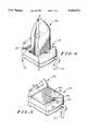
- FIG. 1illustrates a top, front, right side perspective view of a battery charger, an associated portable electronic device, and batteries usable therewith;
- FIG. 2illustrates a top, rear, right side perspective view of the battery charger of FIG. 1;
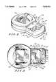
- FIG. 3illustrates a top plan view of the battery charger of FIG. 1;
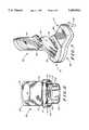
- FIG. 4illustrates a fragmentary top, rear, right side perspective view of the battery charger charging one of the batteries of FIG. 1;
- FIG. 5illustrates a fragmentary top, rear, right side perspective view of the battery charger charging another one of the batteries of FIG. 1;
- FIG. 6illustrates a bottom plan view of the associated portable electronic device of FIG. 1;
- FIG. 7illustrates a top, rear, right side perspective view of the battery charger having the associated portable electronic device and one of the batteries attached thereto;
- FIG. 8is a circuit diagram partially in block diagram form illustrating the battery charger, associated portable electronic device, and batteries of FIG. 1.
- a battery chargerincludes a charging pocket capable of receiving either a first battery in a first orientation or a second battery in a second orientation.
- the charging pocketincludes a first and a second set of contacts.
- the contacts of the first set of contactshave a first spacing so as to mate with contacts disposed on the first battery when the first battery is inserted into the charging pocket.
- the contacts of the second set of contactshave a second spacing so as to mate with contacts disposed on the second battery when the second battery is inserted into the charging pocket.
- FIG. 1illustrates battery charger 100, large battery 102, small battery 104, and electronic device 106.
- FIGS. 2 and 3further illustrate battery charger 100.
- Battery charger 100as shown in FIGS. 1-3, includes housing 108 formed of front pocket 110 and rear pocket 112.
- Front pocket 110includes front well 114 sized to receive electronic device 106.
- Front well 114is formed of base 116 and side walls 117, 118 extending upward therefrom. Side walls 117, 118 include angled slots 119, 120, respectively. Slots 119, 120 are sized to the width of electronic device 106.
- Connector 122is disposed on base 116 between angled slots 119, 120 and extends upward into front well 114.
- the rear pocket 112includes two wells: shallow rear well 130 and deep rear well 132.
- Shallow rear well 130is sized to receive small battery 104.
- Shallow rear well 130is formed of base 134 consisting of a ledge that circumscribes deep rear well 132 and walls extending upward from base 134. These walls include front wall 236 (FIG. 2), side walls 138, 140 (FIG. 1), and rear wall 142.
- Lip 143extends rearward over front wall 236.
- Rear wall 142includes cutaway area 144. Shoulders 146, 148 extend from cutaway area 144 forming receiving slot 150.
- Rear wall 142includes resilient, generally L-shaped, metal spring charging contacts 152 extending outwardly therefrom and positioned to the left and the right of cutaway area 144.
- charging contacts 152include thermistor contact 154 and positive contact 155 located between cutaway area 144 and side wall 138, and negative contact 156 and data contact 157 located between cutaway area 144 and side wall 140. Charging contacts 152 are spaced along the length of rear wall 142.
- Deep rear well 132is sized to receive large battery 102.
- Deep rear well 132is formed of base 160 shaped in accordance with the footprint of the large battery 102 and walls extending upward from base 160. These walls include front wall 162, side wall 164, side wall 366 (FIG. 3), and rear wall 168.
- Front wall 162facially opposes rear wall 142 of shallow rear well 130.
- Front wall 162includes flat charging contacts 170.
- charging contacts 170include, from left to right, positive contact 172, thermistor contact 173, data contact 174, and negative contact 175.
- Charging contacts 170are closely spaced along a mid-portion 176 of front wall 162 (FIG. 2), which is substantially shorter than rear wall 142 (FIG.
- Charging contacts 170are mounted against mid-portion 176 and extend the full depth of deep rear well 132 as shown in FIG. 2.
- Side walls 164, 366include rib member 178 and rib member 380, respectively, extending upward from base 160.
- Battery charger 100is powered via cable 179 extending from housing 108 behind rear pocket 112. Cable 179 connects to a standard wall outlet (not shown) of a main power supply as described in greater detail hereinbelow.
- Large battery 102(FIG. 1) includes housing 180.
- Housing 180includes feet 181, 182 extending substantially orthogonal from front face 186 at bottom end 183.
- Latch 184extends through an opening in housing 180 at top end 185.
- Front face 186 of housing 180includes retractable battery contacts 187.
- Battery contacts 187are linearly arranged parallel to the transverse axis, and orthogonal to the longitudinal axis A1, of large battery 102.
- battery contacts 187include, from left to right, positive contact 188, thermistor contact 189, data contact 190, and negative contact 191.
- Right side 192 of housing 180includes slot 193. Slot 193 extends upward from bottom end 183.
- left side 194 of housing 180is substantially a mirrored image of right side 192 and includes a similarly located and sized slot.
- Large battery 102is inserted feet first into deep rear well 132 of rear pocket 112 as represented by line 195. More particularly, large battery 102 is positioned above deep rear well 132 so that bottom end 183 of large battery 102 is aligned with base 160 of deep rear well 132. Also slot 193 of large battery 102 is aligned with rib member 380 of FIG. 3 of deep rear well 132 and the obscured slot on left side 194 of large battery 102 is aligned with rib member 178 of deep rear well 132. Large battery 102 is then inserted into deep rear well 132 such that slot 193 receives rib member 380 (FIG. 3) and the obscured slot engages rib member 178. Contacts 188-191 (FIG.
- Battery charger 100is electrically connected to large battery 102 to charge large battery 102 when large battery 102 is fully inserted and accepted in deep rear well 132.
- FIG. 4illustrates large battery 102 received by deep rear well 132 of rear pocket 112 of battery charger 100.
- the longitudinal axis of large battery 102maintains an orthogonal orientation with respect to charging contacts 172-175 of deep rear well 132 (FIG. 1).
- Large battery 102is removed by vertically lifting it out of deep rear well 132.
- small battery 104includes housing 196.
- Housing 196includes latch 197 positioned at a midpoint of front end 198.
- Battery contacts 199are positioned around latch 197 on front end 198.
- Battery contacts 199are Hat, metallic members being linearly arranged in a plane orthogonal to the longitudinal axis A2, and parallel to the transverse axis T2, of small battery 104.
- battery contacts 199include, from right to left, thermistor contact 123, positive contact 124, negative contact 125, and data contact 126.
- a protrusion 127is longitudinally disposed on rear end 128 of housing 196.
- small battery 104can be inserted into shallow rear well 130 of rear pocket 112 as represented by line 128.
- small battery 104is angled so that the protrusion 127 is tucked beneath lip 143 of rear pocket 112.
- the small battery 104is then rotated downward into shallow rear well 130 until latch 197 snaps under shoulders 146, 148 and into receiving slot 150 of rear wall 142.
- Contacts 123-126 of small battery 104slide across, and depress inwardly, contacts 154-157 of shallow rear well 130.
- housing 196 of small battery 104is Hush with housing 108 of battery charger 100 and contacts 123-126 contact contacts 154-157, respectively.
- Battery charger 100is electrically connected to small battery 104 to charge small battery 104 when small battery 104 is fully inserted and accepted in shallow rear well 130.
- FIG. 5illustrates small battery 104 received by shallow rear well 130 of rear pocket 112 of battery charger 100.
- the longitudinal axis A2 of small battery 104 positioned in rear pocket 112is orthogonal to the orientation of the longitudinal axis A1 of large battery 102 when, alternatively, received in rear pocket 112.
- Small battery 102is detached by pulling latch 197 away from shoulders 146, 148 and receiving slot 150 and then rotating small battery 104 upward and away from shallow rear recess 130.
- electronic device 106which is illustrated to be a radiotelephone, includes upper housing 109 and lower housing 111 rotatably coupled via hinge 113.
- Upper housing 109includes speaker bezel and openings 115 having a speaker (not shown) mounted therebehind.
- Main battery 121substantially similar to small battery 104, is removably attached to the rear side of upper housing 109 to provide power to electronic device 106.
- Antenna 129extends from lower housing 111.
- Antenna 129is electrically connected to radio circuitry (see FIG. 8) disposed within lower housing 111 and facilitates operation of electronic device 106 in a radiotelephone environment.
- Lower housing 111includes display 131, keypad 133, and microphone opening 135 with a microphone (not shown) mounted therebehind.
- the speaker, display 131, keypad 133, and microphonepermit a user to operate the electronic device 106.
- Lower housing 111includes bottom 137 extending between sides 139, 141.
- Auxiliary battery 136substantially similar to large battery 102, is removably mounted over the rear surface of lower housing 111 to power electronic device 106. Feet 145, 147 of auxiliary battery 136 extend under bottom 137 and hold auxiliary battery 136 on lower housing 111 of electronic device 106.
- FIG. 6shows that bottom 137 includes opening 600 having female connector 602 disposed therebehind.
- Female connector 602mates with connector 122 of FIG. 1 of battery charger 100 when electronic device 106 is inserted into front well 114 of front pocket 110.
- electronic device 106is inserted into front pocket 110, as represented by line 143.
- Electronic device 106is positioned over front well 114 and slightly rearwardly angled so that sides 139, 141 of electronic device 106 align with angled slots 119, 120 of front well 114, respectively.
- Electronic device 106is then moved both downward and frontward such that sides 139, 141 slide down angled slots 119, 120.
- Electronic device 106slides against angled slots 119, 120 until connector 122 mates with connector 602 of FIG. 6, such that electronic device 106 is fully engaged in front pocket 110.
- FIG. 7illustrates electronic device 106 engaged in front well 114 of front pocket 110 of battery charger 100. Once engaged, connector 122 (FIG. 1) of battery charger 100 can deliver power to charge main and auxiliary batteries 121, 136 attached to electronic device 106. FIG. 7 also illustrates small battery 104 received in rear pocket 112 while electronic device 106 is received in front pocket 110. Although not shown, it will be recognized that large battery 102 could alternatively be received in rear pocket 112 while electronic device 106 is received in front pocket 110.
- battery charger 100Aside from the aforementioned connector 122 arid charging contacts 152, 170, battery charger 100 includes controller 800 switch 802, and charge circuitry 804. Battery charger 100 is connected via cable 179 to tracking supply 803. Tracking supply 803 is connected to wall plug 805. Wall plug 805 is connected to a conventional wall outlet (not shown) of a main power supply (e.g., 110 V AC power supply in the U.S.). Tracking supply 803 transforms AC power input by wall plug 805 into DC power and then outputs DC power supplied to battery charger 100 via cable 179. Tracking supply 803 adjusts output DC power according to feedback received from charge circuitry 804 of battery charger 100, or feedback received from electronic device 106 via cable 179. Tracking supply 803 is coupled to switch 802 via cable 179.
- main power supplye.g. 110 V AC power supply in the U.S.
- Controller 800controls the charging operation of battery charger 100. Controller 800 is coupled to connector 122 via bus 806 to communicate with electronic device 106. Controller 800 inputs control signals to switch 802 via bus 808. Controller 800 controls switch 802 to connect tracking supply 803 to either connector 122, via bus 816 when electronic device 106 is attached, or to charge circuitry 804, via bus 818 when large battery 102 or small battery 104 is attached. Controller 800 is connected to thermistor contacts 154, 173 via wire 812 to sense the presence of large battery 102 or small battery 104. Controller 800 is connected to data contacts 157, 174 via wire 814 to read battery data from large battery 102 or small battery 104. Controller 800 is coupled to charge circuitry 804 via bus 810.
- Controller 800controls charge circuitry 804 to deliver charging current to positive contacts 155, 172 via wire 820 according to a predetermined charging algorithm stored in controller 800.
- charge circuitry 804includes a current source and a switched power converter, such as a pulse width modulator (PWM), that generates an output current at a level determined by a switch (not shown) controlled by controller 800.
- PWMpulse width modulator
- Controller 800controls the switch as a function of default data read from a local memory (not shown) or battery data read from large battery 102 or small battery 104.
- Large battery 102includes memory 828, electrochemical cells 830, and thermistor 832.
- Electrochemical cells 830which are coupled in series, include a positive polarity terminal and a negative polarity terminal. The positive polarity terminal is coupled to positive contact 188. The negative polarity terminal is coupled to negative contact 191.
- Electrochemical cells 830are preferably rechargeable, and can be any one of the following types: Nickel-Cadmium (NiCd), Nickel-Metal Hydride (NiMH), Alkaline, or Lithium Ion.
- Memory 828which is coupled to data contact 190, characterizes the large battery 102 as a "smart battery" because the memory 828 stores data that may be used to optimize charging.
- Such dataincludes battery type data, discharge/charge hysteresis data, and history data.
- Thermistor 832is coupled between the negative polarity terminal of electrochemical cells 830 and thermistor contact 189. A voltage level across thermistor 832 indicates the temperature of electrochemical cells 830.
- Small battery 104includes memory 834 coupled to data contact 126, electrochemical cell 836 having a positive polarity terminal coupled to positive contact 124 and a negative polarity terminal coupled to negative contact 125.
- Thermistor 838is coupled between the negative polarity terminal and thermistor contact 123.
- Controller 800responsive to a voltage level on wire 812, reads the battery data on wire 814, connected to memory 828 or memory 834. Controller 800 configures charge circuitry 804 via bus 810 according to the battery data received from the memory. Controller 800 also inputs a control signal to switch 802 via bus 808 that controls switch 802 to connect tracking supply 803 to charge circuitry 804. Tracking supply 803 delivers power to charge circuitry 804 via cable 179 and bus 818. Charge circuitry 804 generates a charging current under the control of controller 800.
- the charging currentis output to positive charging contacts 155, 172 via wire 820 and charges the one of large battery 102 and small battery 104 connected in rear pocket 112. Note that negative contacts 156, 175 are coupled to electrical ground 822. Because only one battery can occupy the rear pocket 112 at any one time, controller 800 and charge circuitry 804 need not discern which contacts 152, 170 to sense, read data from, or deliver charging current to.
- Electronic device 106includes connector 602, radio circuitry 840 coupled to antenna 129, internal charger circuitry 842, main battery 121, and auxiliary battery 136.
- Radio circuitry 840which preferably includes a microprocessor (not shown), communicates with battery charger 100 via bus 844 when inserted in front well 114 and attached to connector 122 of battery charger 100. Responsive to this communication and the presence of tracking supply 803 at connector 602 (also sensed via bus 844), radio circuitry 840 senses the presence of main and auxiliary batteries 121, 136 via buses 852, 854, respectively.
- main and auxiliary batteries 121, 136are charged according to a predetermined priority and only one battery is charged at a time.
- Radio circuitry 840when both batteries are present, main battery 121 is charged prior to auxiliary battery 136. Radio circuitry 840 then reads battery data from either the main battery 121 or the auxiliary battery 136 via bus 852 or bus 854, respectively. Radio circuitry 840, which includes a controller (not shown), controls internal charger circuitry 842 via bus 848 to deliver charging current to either the main battery 121 or the auxiliary battery 136 via bus 850. It will be recognized that the internal charger circuitry 842 includes a controlled current source, such as a PWM. Under control of radio circuitry 840, internal charger circuitry 842 generates a charging current on bus 850 or bus 851 according to a predetermined charging algorithm and either default data or previously read battery data. Internal charger circuitry 842 is powered by tracking supply 803 via connector 602 and bus 846.
- battery charger 100charges according to a predetermined priority. For example, when both front pocket 110 and rear pocket 112 are occupied, switch 802 is first switched to connect tracking supply 803 to front pocket 110 to charge main and auxiliary batteries 121, 136 of electronic device 106. When main and auxiliary batteries 121, 136 of electronic device 106 are fully charged, radio circuitry 840 outputs a signal to controller 800 of battery charger 100 via a path of bus 844, connector 602, connector 122, and bus 806. Controller 800 switches switch 802 to connect tracking supply 803 to charge circuitry 804, which delivers charging current to either large battery 102 or small battery 104 in rear pocket 112. Although electronic device 106 is equipped with internal charger circuitry 842, battery charger 100 can be configured to charge main and auxiliary batteries 121, 136 of electronic device 106 using charge circuitry 804 in absence of internal charger circuitry 842.
- electronic device 106is illustrated as a cellular radiotelephone, it will be recognized that portable computers, cordless telephones, two-way radios, pagers, personal digital assistants, and the like, can also benefit from the multiple battery charger system. Accordingly, “device” as used herein shall refer to any such equipment and their equivalents.
- a battery chargerincludes a charging pocket having at least two sets of charging contacts. Multiple sets of charging contacts disposed in a single pocket are beneficial when an associated electronic device utilizes batteries of different dimensions or having mating contacts at different spacings or positions. By including multiple sets of charging contacts in a single pocket, additional pockets are not necessary and, thus, batteries having different configurations can be accommodated in a relatively compact, low cost, charger.
Landscapes
- Engineering & Computer Science (AREA)
- Power Engineering (AREA)
- Charge And Discharge Circuits For Batteries Or The Like (AREA)
- Battery Mounting, Suspending (AREA)
Abstract
Description
Claims (19)
Priority Applications (4)
| Application Number | Priority Date | Filing Date | Title |
|---|---|---|---|
| US08/550,722US5656914A (en) | 1995-10-31 | 1995-10-31 | Battery charger having pocket with multiple sets of charging contacts |
| CA002187584ACA2187584C (en) | 1995-10-31 | 1996-10-10 | Battery charger |
| CN96120349ACN1079998C (en) | 1995-10-31 | 1996-10-25 | Cell charging device |
| TW085113509ATW350161B (en) | 1995-10-31 | 1996-11-05 | Battery charger |
Applications Claiming Priority (1)
| Application Number | Priority Date | Filing Date | Title |
|---|---|---|---|
| US08/550,722US5656914A (en) | 1995-10-31 | 1995-10-31 | Battery charger having pocket with multiple sets of charging contacts |
Publications (1)
| Publication Number | Publication Date |
|---|---|
| US5656914Atrue US5656914A (en) | 1997-08-12 |
Family
ID=24198345
Family Applications (1)
| Application Number | Title | Priority Date | Filing Date |
|---|---|---|---|
| US08/550,722Expired - LifetimeUS5656914A (en) | 1995-10-31 | 1995-10-31 | Battery charger having pocket with multiple sets of charging contacts |
Country Status (4)
| Country | Link |
|---|---|
| US (1) | US5656914A (en) |
| CN (1) | CN1079998C (en) |
| CA (1) | CA2187584C (en) |
| TW (1) | TW350161B (en) |
Cited By (60)
| Publication number | Priority date | Publication date | Assignee | Title |
|---|---|---|---|---|
| USD394425S (en) | 1996-09-20 | 1998-05-19 | Motorola, Inc. | Battery charger housing |
| US5828966A (en)* | 1996-05-23 | 1998-10-27 | Davis; Russell | Universal charging cradle for cordless telephones |
| USD408783S (en) | 1998-04-13 | 1999-04-27 | Motorola, Inc. | Radiotelephone battery charger housing |
| USD410225S (en) | 1998-10-14 | 1999-05-25 | Senao International Co., Ltd. | Battery charger |
| USD411507S (en) | 1998-05-29 | 1999-06-29 | Motorola, Inc. | Battery charger |
| USD413097S (en) | 1998-01-16 | 1999-08-24 | Yi-Huang Chang | Battery recharger |
| USD414742S (en) | 1997-09-09 | 1999-10-05 | Yi-Huang Chang | Battery recharger |
| US6044281A (en)* | 1995-11-28 | 2000-03-28 | Uniden Corporation | Cordless telephone set having charging terminal configured for holding handset |
| US6049192A (en)* | 1999-03-18 | 2000-04-11 | Motorola, Inc. | Battery charger having moving door housing for a battery |
| USD426533S (en)* | 1997-11-25 | 2000-06-13 | Swatch Ag | Telephone |
| US6124699A (en)* | 1998-09-11 | 2000-09-26 | Matsushita Electric Industrial, Co., Ltd. | Battery charger device |
| US6127802A (en)* | 1999-11-19 | 2000-10-03 | Motorola, Inc. | Charger with battery retention door |
| WO2000074168A1 (en)* | 1999-05-28 | 2000-12-07 | Samsung Electronics Co., Ltd. | Portable battery charger |
| US6204632B1 (en)* | 1999-09-08 | 2001-03-20 | Selfcharge | Apparatus for charging multiple batteries |
| US6281425B1 (en)* | 2000-04-04 | 2001-08-28 | 3Com Corporation | Apparatus and method of recharging a handheld computing device using solar power |
| US6346793B1 (en)* | 1999-10-26 | 2002-02-12 | Makita Corporation | Battery charger with a terminal protector |
| US6362987B1 (en) | 2000-12-27 | 2002-03-26 | John Yurek | Wall mounted electrical outlet receptacle for providing low voltage DC current |
| GB2367432A (en)* | 2000-09-20 | 2002-04-03 | Pag Ltd | Connector for receiving one of two different configurations of battery |
| US20020187675A1 (en)* | 2001-05-09 | 2002-12-12 | Mcmullin Faris W. | Integrated cord take-up assembly |
| USD468305S1 (en) | 2002-04-30 | 2003-01-07 | Motorola, Inc. | Base for receiving a portable communication device or for receiving similar articles |
| US20030090234A1 (en)* | 2001-11-09 | 2003-05-15 | Glasgow Kevin L. | Battery charger |
| US6617824B1 (en) | 2002-02-27 | 2003-09-09 | Motorola, Inc. | Battery charger pocket apparatus for receiving multiple battery |
| US6633152B2 (en) | 2001-04-26 | 2003-10-14 | Streamlight, Inc. | Rechargeable flashlight and battery charger |
| US6652115B2 (en)* | 2001-10-26 | 2003-11-25 | Streamlight, Inc. | Battery charger structure and rechargeable flashlight system using the same |
| US20040135542A1 (en)* | 2002-10-21 | 2004-07-15 | Makita Corporation | Battery charger with improved terminal protection |
| US20040204056A1 (en)* | 2002-12-06 | 2004-10-14 | William Phelps | Charger with rotating pocket and detachable pocket insert |
| US20050024021A1 (en)* | 2003-05-07 | 2005-02-03 | Milwaukee Electric Tool Corporation | Battery charger and assembly |
| USD515062S1 (en)* | 2004-06-24 | 2006-02-14 | Sierra Wireless | Cradle for an electronic communication device |
| USD524243S1 (en)* | 2003-11-13 | 2006-07-04 | Samsung Electronics Co., Ltd. | Charger for information terminals |
| US20070043962A1 (en)* | 2005-08-18 | 2007-02-22 | Fuji Photo Film Co., Ltd. | Data processing apparatus and data processing method |
| USD564501S1 (en)* | 2004-11-22 | 2008-03-18 | Gn Netcom A/S | Base unit with a headset |
| USD566697S1 (en)* | 2006-03-03 | 2008-04-15 | Gn Netcom A/S | Wireless headset base |
| US20080224661A1 (en)* | 2006-11-20 | 2008-09-18 | Onose Katsuya | Charging device for portable electronic device battery and portable phone battery |
| USD582901S1 (en)* | 2007-08-10 | 2008-12-16 | Plantronics, Inc. | Base for a communications headset |
| USD593998S1 (en)* | 2007-08-14 | 2009-06-09 | Plantronics, Inc. | Base cradle for a communications headset |
| USD599331S1 (en)* | 2009-01-14 | 2009-09-01 | Plantronics, Inc. | Base for a communications headset |
| USD614608S1 (en)* | 2008-09-08 | 2010-04-27 | Tag Heuer Sa | Base station for headset for mobile phone |
| US20100109605A1 (en)* | 2008-11-06 | 2010-05-06 | Toshiki Nakasho | Battery charger for two types of rectangular battery packs |
| USD639788S1 (en)* | 2007-12-05 | 2011-06-14 | Phonic Ear A/S | Wireless hearing device docking station |
| USD643834S1 (en)* | 2010-06-03 | 2011-08-23 | Plantronics, Inc. | Base cradle for a communications headset |
| US8378630B2 (en) | 2006-10-13 | 2013-02-19 | Nyko Technologies, Inc. | Video game controller charging system having a docking structure |
| USD702214S1 (en)* | 2012-08-29 | 2014-04-08 | Samsung Electronics Co., Ltd. | Speaker stand |
| US20160094076A1 (en)* | 2014-09-29 | 2016-03-31 | Apple Inc. | Inductive charging between electronic devices |
| US20160380458A1 (en)* | 2015-06-26 | 2016-12-29 | Intel Corporation | Electronic device to be directly charged |
| US9641002B2 (en) | 2011-09-02 | 2017-05-02 | Pag Ltd. | Battery management system, method and battery |
| US9653719B2 (en) | 2013-10-04 | 2017-05-16 | Pag Ltd. | Battery |
| US10027078B2 (en) | 2014-01-02 | 2018-07-17 | Sears Brands, L.L.C. | Slide battery and power tool for use with both slide and post batteries |
| USD855570S1 (en)* | 2018-04-17 | 2019-08-06 | Averchenko Evgeniy Vladimirovich | Cable connector |
| US10542109B2 (en) | 2014-05-30 | 2020-01-21 | Apple Inc. | Proxied push |
| US10553843B2 (en) | 2016-03-28 | 2020-02-04 | Transform Sr Brands Llc | Portable power tool, battery pack, and cell configurations for same |
| US10797496B2 (en) | 2018-05-02 | 2020-10-06 | Rufus Labs, Inc. | Modular charging station |
| USD898000S1 (en)* | 2018-09-13 | 2020-10-06 | Plantronics, Inc. | Base cradle for a communications headset |
| US11133681B2 (en)* | 2011-04-28 | 2021-09-28 | Zoll Circulation, Inc. | System and method for tracking and archiving battery performance data |
| US20210336383A1 (en)* | 2020-04-22 | 2021-10-28 | Shenzhen Chenbei Technology Co., Ltd. | Mounting bracket and electronic device |
| US11502526B2 (en)* | 2018-04-26 | 2022-11-15 | Brother Kogyo Kabushiki Kaisha | Battery charger capable of holding battery at its charging posture and retracted posture |
| WO2023183709A1 (en)* | 2022-03-21 | 2023-09-28 | Hollister Incorporated | Charging dock for ostomy leakage detection system |
| USD1024011S1 (en)* | 2022-10-21 | 2024-04-23 | Libin Chen | Headphone and charger |
| USD1024010S1 (en)* | 2022-10-21 | 2024-04-23 | Libin Chen | Headphone and charger |
| US12107444B2 (en) | 2011-04-28 | 2024-10-01 | Zoll Circulation, Inc. | Viral distribution of battery management parameters |
| USD1051039S1 (en) | 2022-09-19 | 2024-11-12 | Hollister Incorporated | Charging dock |
Families Citing this family (2)
| Publication number | Priority date | Publication date | Assignee | Title |
|---|---|---|---|---|
| DE112017006827T5 (en)* | 2017-01-13 | 2019-10-02 | Symbol Technologies, Llc | INTERCHANGEABLE CHARGING STATION, BATTERY PACK AND MOBILE DEVICE |
| CN109017950A (en)* | 2017-06-09 | 2018-12-18 | 江苏弘冠智能科技有限公司 | Multifunctional shopping cart |
Citations (6)
| Publication number | Priority date | Publication date | Assignee | Title |
|---|---|---|---|---|
| US5059885A (en)* | 1989-08-23 | 1991-10-22 | Motorola, Inc. | Battery charger with battery positioning and support apparatus |
| US5327067A (en)* | 1993-06-02 | 1994-07-05 | Dell Usa, L.P. | Portable computer battery charging apparatus |
| USD349883S (en) | 1991-08-09 | 1994-08-23 | Skil and S-B Power Tool Company | Battery charger with means for supporting dual battery packs and tool |
| US5347208A (en)* | 1992-05-26 | 1994-09-13 | Matsushita Electric Industrial Co., Ltd. | Charging equipment for charging a portable apparatus and separable cell pack |
| USD353131S (en) | 1993-10-29 | 1994-12-06 | Motorola, Inc. | Battery charger for a portable telephone |
| US5525888A (en)* | 1993-05-14 | 1996-06-11 | Sanyo Electric Co., Ltd. | Battery charger, battery case, and electronic equipment |
- 1995
- 1995-10-31USUS08/550,722patent/US5656914A/ennot_activeExpired - Lifetime
- 1996
- 1996-10-10CACA002187584Apatent/CA2187584C/ennot_activeExpired - Fee Related
- 1996-10-25CNCN96120349Apatent/CN1079998C/ennot_activeExpired - Lifetime
- 1996-11-05TWTW085113509Apatent/TW350161B/ennot_activeIP Right Cessation
Patent Citations (6)
| Publication number | Priority date | Publication date | Assignee | Title |
|---|---|---|---|---|
| US5059885A (en)* | 1989-08-23 | 1991-10-22 | Motorola, Inc. | Battery charger with battery positioning and support apparatus |
| USD349883S (en) | 1991-08-09 | 1994-08-23 | Skil and S-B Power Tool Company | Battery charger with means for supporting dual battery packs and tool |
| US5347208A (en)* | 1992-05-26 | 1994-09-13 | Matsushita Electric Industrial Co., Ltd. | Charging equipment for charging a portable apparatus and separable cell pack |
| US5525888A (en)* | 1993-05-14 | 1996-06-11 | Sanyo Electric Co., Ltd. | Battery charger, battery case, and electronic equipment |
| US5327067A (en)* | 1993-06-02 | 1994-07-05 | Dell Usa, L.P. | Portable computer battery charging apparatus |
| USD353131S (en) | 1993-10-29 | 1994-12-06 | Motorola, Inc. | Battery charger for a portable telephone |
Non-Patent Citations (2)
| Title |
|---|
| NTT Do Co Mo, Mo Va, 94 4, Japan, pp. 1, 88, 90. 1994.* |
| NTT Do Co Mo, Mo Va, 94-4, Japan, pp. 1, 88, 90. 1994. |
Cited By (97)
| Publication number | Priority date | Publication date | Assignee | Title |
|---|---|---|---|---|
| US6044281A (en)* | 1995-11-28 | 2000-03-28 | Uniden Corporation | Cordless telephone set having charging terminal configured for holding handset |
| US5828966A (en)* | 1996-05-23 | 1998-10-27 | Davis; Russell | Universal charging cradle for cordless telephones |
| USD394425S (en) | 1996-09-20 | 1998-05-19 | Motorola, Inc. | Battery charger housing |
| USD414742S (en) | 1997-09-09 | 1999-10-05 | Yi-Huang Chang | Battery recharger |
| USD426533S (en)* | 1997-11-25 | 2000-06-13 | Swatch Ag | Telephone |
| USD413097S (en) | 1998-01-16 | 1999-08-24 | Yi-Huang Chang | Battery recharger |
| USD408783S (en) | 1998-04-13 | 1999-04-27 | Motorola, Inc. | Radiotelephone battery charger housing |
| USD411507S (en) | 1998-05-29 | 1999-06-29 | Motorola, Inc. | Battery charger |
| US6124699A (en)* | 1998-09-11 | 2000-09-26 | Matsushita Electric Industrial, Co., Ltd. | Battery charger device |
| USD410225S (en) | 1998-10-14 | 1999-05-25 | Senao International Co., Ltd. | Battery charger |
| US6049192A (en)* | 1999-03-18 | 2000-04-11 | Motorola, Inc. | Battery charger having moving door housing for a battery |
| AU750285B2 (en)* | 1999-05-28 | 2002-07-11 | Samsung Electronics Co., Ltd. | Portable battery charger |
| WO2000074168A1 (en)* | 1999-05-28 | 2000-12-07 | Samsung Electronics Co., Ltd. | Portable battery charger |
| GB2354893A (en)* | 1999-05-28 | 2001-04-04 | Samsung Electronics Co Ltd | Portable battery charger |
| US6265845B1 (en) | 1999-05-28 | 2001-07-24 | Samsung Electronics Co., Ltd. | Portable battery charger having a separate battery pack |
| GB2354893B (en)* | 1999-05-28 | 2004-01-07 | Samsung Electronics Co Ltd | Portable battery charger |
| US6204632B1 (en)* | 1999-09-08 | 2001-03-20 | Selfcharge | Apparatus for charging multiple batteries |
| US6346793B1 (en)* | 1999-10-26 | 2002-02-12 | Makita Corporation | Battery charger with a terminal protector |
| US6127802A (en)* | 1999-11-19 | 2000-10-03 | Motorola, Inc. | Charger with battery retention door |
| WO2001037394A1 (en)* | 1999-11-19 | 2001-05-25 | Motorola Inc. | Charger with battery retention door |
| US6281425B1 (en)* | 2000-04-04 | 2001-08-28 | 3Com Corporation | Apparatus and method of recharging a handheld computing device using solar power |
| GB2367432A (en)* | 2000-09-20 | 2002-04-03 | Pag Ltd | Connector for receiving one of two different configurations of battery |
| US6638086B2 (en) | 2000-09-20 | 2003-10-28 | Pag Limited | Configurable battery connector |
| GB2367432B (en)* | 2000-09-20 | 2004-06-09 | Pag Ltd | Configurable battery connector |
| US6362987B1 (en) | 2000-12-27 | 2002-03-26 | John Yurek | Wall mounted electrical outlet receptacle for providing low voltage DC current |
| USRE42945E1 (en) | 2001-04-26 | 2011-11-22 | Streamlight, Inc. | Rechargeable flashlight and battery charger |
| US6633152B2 (en) | 2001-04-26 | 2003-10-14 | Streamlight, Inc. | Rechargeable flashlight and battery charger |
| US20020187675A1 (en)* | 2001-05-09 | 2002-12-12 | Mcmullin Faris W. | Integrated cord take-up assembly |
| US6652115B2 (en)* | 2001-10-26 | 2003-11-25 | Streamlight, Inc. | Battery charger structure and rechargeable flashlight system using the same |
| US20030090234A1 (en)* | 2001-11-09 | 2003-05-15 | Glasgow Kevin L. | Battery charger |
| US20080100261A1 (en)* | 2001-11-09 | 2008-05-01 | Glasgow Kevin L | Battery charger |
| US7332889B2 (en) | 2001-11-09 | 2008-02-19 | Milwaukee Electric Tool Corporation | Battery charger |
| US6617824B1 (en) | 2002-02-27 | 2003-09-09 | Motorola, Inc. | Battery charger pocket apparatus for receiving multiple battery |
| USD468305S1 (en) | 2002-04-30 | 2003-01-07 | Motorola, Inc. | Base for receiving a portable communication device or for receiving similar articles |
| US20040135542A1 (en)* | 2002-10-21 | 2004-07-15 | Makita Corporation | Battery charger with improved terminal protection |
| US7064519B2 (en)* | 2002-10-21 | 2006-06-20 | Makita Corporation | Battery charger with improved terminal protection |
| US20040204056A1 (en)* | 2002-12-06 | 2004-10-14 | William Phelps | Charger with rotating pocket and detachable pocket insert |
| US20080036420A1 (en)* | 2003-05-07 | 2008-02-14 | Zeiler Jeffrey M | Battery charger and assembly |
| US7659696B2 (en) | 2003-05-07 | 2010-02-09 | Milwaukee Electric Tool Corporation | Battery charger and assembly |
| US20050024021A1 (en)* | 2003-05-07 | 2005-02-03 | Milwaukee Electric Tool Corporation | Battery charger and assembly |
| USD524243S1 (en)* | 2003-11-13 | 2006-07-04 | Samsung Electronics Co., Ltd. | Charger for information terminals |
| USD515062S1 (en)* | 2004-06-24 | 2006-02-14 | Sierra Wireless | Cradle for an electronic communication device |
| USD564501S1 (en)* | 2004-11-22 | 2008-03-18 | Gn Netcom A/S | Base unit with a headset |
| US7647511B2 (en)* | 2005-08-18 | 2010-01-12 | Fujifilm Corporation | Method for charging data processing apparatus having two separate units |
| US20070043962A1 (en)* | 2005-08-18 | 2007-02-22 | Fuji Photo Film Co., Ltd. | Data processing apparatus and data processing method |
| USD566697S1 (en)* | 2006-03-03 | 2008-04-15 | Gn Netcom A/S | Wireless headset base |
| US9174121B2 (en) | 2006-10-13 | 2015-11-03 | Nyko Technologies, Inc. | Video game controller charging system having a docking structure |
| US9705344B2 (en) | 2006-10-13 | 2017-07-11 | Nyko Technologies, Inc. | Video game controller charging system having a docking structure |
| US8536832B2 (en) | 2006-10-13 | 2013-09-17 | Nyko Technologies, Inc. | Video game controller charging system having a docking structure |
| US8633675B2 (en) | 2006-10-13 | 2014-01-21 | Nyko Technologies, Inc. | Video game controller charging system having a docking structure |
| US8378630B2 (en) | 2006-10-13 | 2013-02-19 | Nyko Technologies, Inc. | Video game controller charging system having a docking structure |
| US20080224661A1 (en)* | 2006-11-20 | 2008-09-18 | Onose Katsuya | Charging device for portable electronic device battery and portable phone battery |
| US7839119B2 (en)* | 2006-11-20 | 2010-11-23 | Nec Tokin Corporation | Charging device for portable electronic device battery and portable phone battery |
| USD582901S1 (en)* | 2007-08-10 | 2008-12-16 | Plantronics, Inc. | Base for a communications headset |
| USD593998S1 (en)* | 2007-08-14 | 2009-06-09 | Plantronics, Inc. | Base cradle for a communications headset |
| USD639788S1 (en)* | 2007-12-05 | 2011-06-14 | Phonic Ear A/S | Wireless hearing device docking station |
| USD614608S1 (en)* | 2008-09-08 | 2010-04-27 | Tag Heuer Sa | Base station for headset for mobile phone |
| US20100109605A1 (en)* | 2008-11-06 | 2010-05-06 | Toshiki Nakasho | Battery charger for two types of rectangular battery packs |
| US8120318B2 (en)* | 2008-11-06 | 2012-02-21 | Sanyo Electric Co., Ltd. | Battery charger for two types of rectangular battery packs |
| USD599331S1 (en)* | 2009-01-14 | 2009-09-01 | Plantronics, Inc. | Base for a communications headset |
| USD643834S1 (en)* | 2010-06-03 | 2011-08-23 | Plantronics, Inc. | Base cradle for a communications headset |
| US12107444B2 (en) | 2011-04-28 | 2024-10-01 | Zoll Circulation, Inc. | Viral distribution of battery management parameters |
| US11133681B2 (en)* | 2011-04-28 | 2021-09-28 | Zoll Circulation, Inc. | System and method for tracking and archiving battery performance data |
| US9641002B2 (en) | 2011-09-02 | 2017-05-02 | Pag Ltd. | Battery management system, method and battery |
| USD702214S1 (en)* | 2012-08-29 | 2014-04-08 | Samsung Electronics Co., Ltd. | Speaker stand |
| US9653719B2 (en) | 2013-10-04 | 2017-05-16 | Pag Ltd. | Battery |
| US11258217B2 (en) | 2014-01-02 | 2022-02-22 | Transform Sr Brands Llc | Power tool and system |
| US10027078B2 (en) | 2014-01-02 | 2018-07-17 | Sears Brands, L.L.C. | Slide battery and power tool for use with both slide and post batteries |
| US10608391B2 (en) | 2014-01-02 | 2020-03-31 | Transform Sr Brands Llc | Slide battery and power tool for use with both slide and post batteries |
| US10542109B2 (en) | 2014-05-30 | 2020-01-21 | Apple Inc. | Proxied push |
| US10886769B2 (en)* | 2014-09-29 | 2021-01-05 | Apple Inc. | Inductive charging between electronic devices |
| US10505386B2 (en)* | 2014-09-29 | 2019-12-10 | Apple Inc. | Inductive charging between electronic devices |
| US20190386507A1 (en)* | 2014-09-29 | 2019-12-19 | Apple Inc. | Inductive charging between electronic devices |
| US20160094076A1 (en)* | 2014-09-29 | 2016-03-31 | Apple Inc. | Inductive charging between electronic devices |
| US10404089B2 (en)* | 2014-09-29 | 2019-09-03 | Apple Inc. | Inductive charging between electronic devices |
| US10886771B2 (en)* | 2014-09-29 | 2021-01-05 | Apple Inc. | Inductive charging between electronic devices |
| US10003206B2 (en) | 2015-06-26 | 2018-06-19 | Intel Corporation | Electronic device to be directly charged by a charging device |
| US10432003B2 (en) | 2015-06-26 | 2019-10-01 | Intel Corporation | Electronic device to be directly charged by a charging device with a protection mechanism |
| US20160380458A1 (en)* | 2015-06-26 | 2016-12-29 | Intel Corporation | Electronic device to be directly charged |
| JP2018520621A (en)* | 2015-06-26 | 2018-07-26 | インテル コーポレイション | Directly charged electronic device |
| US10666061B2 (en) | 2015-06-26 | 2020-05-26 | Intel Corporation | Electronic power device with protection cover |
| US9780588B2 (en)* | 2015-06-26 | 2017-10-03 | Intel Corporation | Electronic device to be directly charged by a charging device |
| US11031653B2 (en) | 2016-03-28 | 2021-06-08 | Transform Sr Brands Llc | Portable power tool, battery pack, and cell configurations for same |
| US11962024B2 (en) | 2016-03-28 | 2024-04-16 | Transform Sr Brands Llc | Portable power tool, battery pack, and cell configurations for same |
| US11588201B2 (en) | 2016-03-28 | 2023-02-21 | Transform Sr Brands Llc | Portable power tool, battery pack, and cell configurations for same |
| US10553843B2 (en) | 2016-03-28 | 2020-02-04 | Transform Sr Brands Llc | Portable power tool, battery pack, and cell configurations for same |
| USD855570S1 (en)* | 2018-04-17 | 2019-08-06 | Averchenko Evgeniy Vladimirovich | Cable connector |
| US11502526B2 (en)* | 2018-04-26 | 2022-11-15 | Brother Kogyo Kabushiki Kaisha | Battery charger capable of holding battery at its charging posture and retracted posture |
| US10797496B2 (en) | 2018-05-02 | 2020-10-06 | Rufus Labs, Inc. | Modular charging station |
| USD933637S1 (en) | 2018-09-13 | 2021-10-19 | Plantronics, Inc. | Base cradle for a communications headset |
| USD898000S1 (en)* | 2018-09-13 | 2020-10-06 | Plantronics, Inc. | Base cradle for a communications headset |
| US20210336383A1 (en)* | 2020-04-22 | 2021-10-28 | Shenzhen Chenbei Technology Co., Ltd. | Mounting bracket and electronic device |
| US11682858B2 (en)* | 2020-04-22 | 2023-06-20 | Shenzhen Chenbei Technology Co., Ltd. | Mounting bracket and electronic device |
| WO2023183709A1 (en)* | 2022-03-21 | 2023-09-28 | Hollister Incorporated | Charging dock for ostomy leakage detection system |
| USD1051039S1 (en) | 2022-09-19 | 2024-11-12 | Hollister Incorporated | Charging dock |
| USD1024011S1 (en)* | 2022-10-21 | 2024-04-23 | Libin Chen | Headphone and charger |
| USD1024010S1 (en)* | 2022-10-21 | 2024-04-23 | Libin Chen | Headphone and charger |
Also Published As
| Publication number | Publication date |
|---|---|
| CA2187584C (en) | 1999-12-28 |
| TW350161B (en) | 1999-01-11 |
| CN1079998C (en) | 2002-02-27 |
| CA2187584A1 (en) | 1997-05-01 |
| CN1155171A (en) | 1997-07-23 |
Similar Documents
| Publication | Publication Date | Title |
|---|---|---|
| US5656914A (en) | Battery charger having pocket with multiple sets of charging contacts | |
| US6049192A (en) | Battery charger having moving door housing for a battery | |
| US5280229A (en) | Charging device for rechargeable batteries | |
| US8253371B2 (en) | Electronic device including handheld electronic device with dual battery configuration, and associated method | |
| US4829224A (en) | Battery pack for cellular telephone | |
| US7268519B2 (en) | Portable battery charger for a mobile device | |
| AU2007222067B2 (en) | Battery charger | |
| US5059885A (en) | Battery charger with battery positioning and support apparatus | |
| US20050024011A1 (en) | Charger for cellular phone | |
| EP1352443A2 (en) | Back-up battery for a cellular telephone | |
| US6154010A (en) | Battery charging docking cradle for a mobile computer | |
| JP2006504240A (en) | Exterior battery pack | |
| CN1075266C (en) | Intelligent variable battery charger current control device and electronic unit charging method | |
| EP2015422B1 (en) | Electronic device including handheld electronic device with dual battery configuration, and associated method | |
| US5959434A (en) | Mechanical charging selection apparatus | |
| EP1921725B1 (en) | Electronic device, including handheld electronic device, with dual battery configuration and associated method | |
| JP2003164070A (en) | Charger | |
| KR20040026318A (en) | Battery Recharging Device | |
| WO1997045997A1 (en) | Battery charging unit | |
| KR19990035608A (en) | Battery charger | |
| HK1018127B (en) | Intelligent variable battery charger current control apparatus charging method for an electronic unit | |
| KR20020085363A (en) | A battery charger of mobile phone | |
| HK1079346A (en) | Method and apparatus for a dual battery configuration of a hendheld device and holder |
Legal Events
| Date | Code | Title | Description |
|---|---|---|---|
| AS | Assignment | Owner name:MOTOROLA, INC., ILLINOIS Free format text:ASSIGNMENT OF ASSIGNORS INTEREST;ASSIGNORS:NAGELE, ALBERT L.;DOMOLECZNY, JAMES D.;REMY, STEVEN R.;AND OTHERS;REEL/FRAME:007875/0096;SIGNING DATES FROM 19960131 TO 19960209 | |
| STCF | Information on status: patent grant | Free format text:PATENTED CASE | |
| FPAY | Fee payment | Year of fee payment:4 | |
| FPAY | Fee payment | Year of fee payment:8 | |
| FPAY | Fee payment | Year of fee payment:12 | |
| AS | Assignment | Owner name:MOTOROLA MOBILITY, INC, ILLINOIS Free format text:ASSIGNMENT OF ASSIGNORS INTEREST;ASSIGNOR:MOTOROLA, INC;REEL/FRAME:025673/0558 Effective date:20100731 | |
| AS | Assignment | Owner name:MOTOROLA MOBILITY LLC, ILLINOIS Free format text:CHANGE OF NAME;ASSIGNOR:MOTOROLA MOBILITY, INC.;REEL/FRAME:029216/0282 Effective date:20120622 | |
| AS | Assignment | Owner name:GOOGLE TECHNOLOGY HOLDINGS LLC, CALIFORNIA Free format text:ASSIGNMENT OF ASSIGNORS INTEREST;ASSIGNOR:MOTOROLA MOBILITY LLC;REEL/FRAME:034303/0001 Effective date:20141028 | |
| AS | Assignment | Owner name:AMPEREX TECHNOLOGY LIMITED, HONG KONG Free format text:ASSIGNMENT OF ASSIGNORS INTEREST;ASSIGNOR:GOOGLE TECHNOLOGY HOLDINGS LLC;REEL/FRAME:046392/0764 Effective date:20180604 |