US5656782A - Pressure sealed housing apparatus and methods - Google Patents
Pressure sealed housing apparatus and methodsDownload PDFInfo
- Publication number
- US5656782A US5656782AUS08/449,104US44910495AUS5656782AUS 5656782 AUS5656782 AUS 5656782AUS 44910495 AUS44910495 AUS 44910495AUS 5656782 AUS5656782 AUS 5656782A
- Authority
- US
- United States
- Prior art keywords
- mounting
- compartment
- axis
- housing apparatus
- mounting seat
- Prior art date
- Legal status (The legal status is an assumption and is not a legal conclusion. Google has not performed a legal analysis and makes no representation as to the accuracy of the status listed.)
- Expired - Lifetime
Links
Images


Classifications
- G—PHYSICS
- G01—MEASURING; TESTING
- G01L—MEASURING FORCE, STRESS, TORQUE, WORK, MECHANICAL POWER, MECHANICAL EFFICIENCY, OR FLUID PRESSURE
- G01L19/00—Details of, or accessories for, apparatus for measuring steady or quasi-steady pressure of a fluent medium insofar as such details or accessories are not special to particular types of pressure gauges
- G01L19/14—Housings
Definitions
- This inventionrelates to housings for electrical elements. More specifically, the invention provides an improved housing for process electronics associated with a measuring or sensing device, such as a differential pressure transmitter.
- Differential pressure transmittersare commonly used in process control systems that require pressure, flowrate, or measurements of other variables associated with gases and liquids.
- One typical prior differential pressure transmitteremploys a two-section housing assembly. A lower section of the transmitter assembly communicates with an upper section of the transmitter assembly by way of a port extending between the two sections.
- the lower sectiontypically houses, among other components, two process diaphragms and a transducer.
- the lower sectionincludes two process fluid ports for coupling to input process lines for exposing each process diaphragm to one of two fluid pressures that are to be compared.
- Each process diaphragmdeflects in response to,the pressure of one fluid.
- the transducerresponds to the difference between the two pressures of the process fluids, and produces electrical output signals for indication or control.
- the upper sectiontypically houses process electronics, i.e. electronic circuits and electrical components for monitoring and conditioning the electrical output signals from the transducer for transmission to a display meter, and/or for application to a control valve, a computer or another electronic device.
- process electronicsi.e. electronic circuits and electrical components for monitoring and conditioning the electrical output signals from the transducer for transmission to a display meter, and/or for application to a control valve, a computer or another electronic device.
- the conditioned signalsare to be applied to a computer or other electronic device, they can be coupled out of the second section of the housing assembly, by way of fittings to electrical conduits.
- Typical process fluidscan be corrosive and/or toxic. Accordingly, the upper section of the housing assembly, which contains the process electronics, is isolated from the process fluids that are coupled to the lower section of the housing assembly. Since the process fluids are only applied to one side of each process diaphragm, the two process diaphragms and lower section of the housing assembly form a chamber that is isolated from the process fluids and is generally filled with an inert fill fluid. Additionally, this chamber leads to a transducer for generating the electrical output signals to the process electronics.
- One disadvantage of some prior fluid measuring systems of the foregoing typeis that if either process diaphragm fails, the process fluid can displace the inert fill fluid and the corrosives or volatiles may eventually vent throughout the upper section of the housing assembly, destroying the process electronics. Additionally, the process fluids can then vent from the second section through the electrical conduits, by way of the fittings in the housing assembly. This can be especially dangerous if the process fluids are toxic or flammable.
- Some prior housing assembliesaddress this problem by providing a barrier wall that divides the second section into two compartments; one containing the port for communicating between the first and second sections of the housing assembly and the other containing the fittings that couple to the electrical conduits.
- the upper section of the housing assemblyis accessible at two axial ends by way of threaded covers. While these assemblies provide access to the upper section of the housing assembly, they may have significant disadvantages.
- One such disadvantagearises because the prior art assemblies typically provide only two compartments in the upper section. Thus, if a cover is removed, all of the electronics housed in that compartment are exposed to the outside environment. Hence, operation in a humid environment can, once again, require the circuits contained in the upper section to be sealed from moisture.
- Another disadvantageis that such covers allow unrestricted access to the electronics. Thus, the instrument can be inadvertently damaged or subjected to tampering.
- Another objectis to provide a housing assembly that provides improved flexibility with regard to arranging process electronics in the housing, while still ensuring that process fluids are blocked from the electrical conduits.
- a further object of the inventionis to provide a housing assembly that has improved access, and yet is tamper-resistant.
- An additional object of the inventionis to provide a housing assembly that minimizes environmentally infiltration while eliminating the need for seal-coating the process electronics, by potting or otherwise.
- Yet another object of the inventionis to provide a housing structure that has relatively few parts and is relatively economical to manufacture, and that can house a variety of processing electronics, for varied commercial applications.
- the inventionattains these and other objects by providing, in one embodiment, a selectively pressured housing apparatus for electrical elements.
- the housing apparatushas a body, a wall member, an aperture, and a mounting seat.
- the bodyhas a chamber therein extending along a first axis, is open at a first axial end and at a second axial end, and has a port extending along a second axis transverse to the first axis.
- the portcommunicates with the chamber.
- the wall memberis inside of the body and extends transverse to the first axis and parallel to the second axis and divides the chamber into first and second compartments, which are axially spaced along the first axis.
- the port communicating with the chamberis in the second compartment.
- the apertureextends through the wall member and communicates between the first and second compartments.
- the mounting seatis on the wall member and extends circumferentially about the aperture for removably and replaceably seating an electro-mechanical element with a selected pressure seal to the wall member.
- the first and second compartmentshouse process electronics associated with a differential pressure transmitter.
- the port for communicating with the chambercan mount to a second housing structure that contains process diaphragms, a pressure transducer, and other components for coupling electrical signals indicative of a differential pressure to the process electronics.
- the mounting seatprojects axially along the first axis into the first compartment from the wall member.
- a channelextends circumferentially around the mounting seat and has a depth extending along the first axis.
- the channelcan store a service loop of electrical wire, which can be connected, for example, to the electro-mechanical element seated to the mounting seat.
- the mounting seatcan have a variety of configurations.
- the mounting seatincludes a planar surface facing along the first axis into the first compartment for removably and replaceably seating the electro-mechanical element, with a selected pressure seal, to the planar surface.
- the mounting seathas a finished surface, such as a tubular surface, extending axially along said first axis.
- the electromechanical elementis mounted to the mounting seat by way of the first compartment, and when mounted, is disposed in the first compartment.
- the mounting seatcan further include fastening threads for the removable and replaceable mounting of the electro-mechanical element.
- the fastening threadsare formed in a plurality of mounting holes axially extending into the mounting seat.
- the fastening threadscan be formed on a plurality of mounting studs, axially projecting from the mounting seat.
- the electronics contained in the housing apparatustypically require maintenance, repair, and calibration. Therefore, according to one embodiment of the invention, at least one axial end of the housing body is threaded for removable and replaceable assembly with an end-cap for selectively closing that end of the body. In apparatus including such an end-cap, it may be desirable to regulate access. Consequently, according to a further feature, the invention provides a tamper-resistant construction in which the threaded end-cap has a substantially cylindrical outer surface, with radial recesses therein spaced circumferentially about the outer surface. The apparatus further includes a stem threadably mounted on the housing body.
- the stemhas a radially large portion that selectively engages in one radial recess of the end-cap for precluding rotation of the end-cap relative to the body.
- the stemis mounted in a threaded aperture located adjacent to the end of the body that mounts the end-cap.
- the threaded apertureextends axially into the housing body along an axis parallel to the first axis.
- the stemcan mount in the threaded apeme so that the radially large portion of the stem protrudes from the threaded aperture and selectively seats in a radial recess in the end-cap.
- the threaded aperturecan also include a passage extending therethrough for receiving a filament to engage a flatted portion of the stem to preclude threading the stem, and thereby to lock it in place.
- the filamentcan be fastened to preclude removal, thereby, limiting access to the electronic circuitry within the housing.
- the port of the housing apparatusincludes a collar on the body and extending along the second axis.
- the collarhas a through passage for communication with the second compartment, and has a tubular outer surface for seating a label.
- the collarhas a radial projection for fixing the rotational position of the label.
- Housing apparatuscan include an electrical terminal-block fitting removable and replaceable relative to the first compartment, by way of the first open end.
- the terminal-block fittinghas a mounting portion for removably and replaceably seating with the mounting seat, for selectively mounting the fittingrelative to the wall member with a selected pressure seal between the first and second compartments.
- the terminal-block fittingcan include a selected set of first electrical terminals arranged for removable and replaceable connection from the first compartment when the terminal-block fitting is mounted to the wall member.
- the terminal-block fittingincludes a selected set of second electrical terminals in electrical circuit communication with the first electrical terminals and arranged for removable and replaceable connection from the second compartment, when the fitting is mounted to the wall member.
- the electrical terminal-block fittingincludes a terminal block and a printed circuit board.
- the printed circuit boardhas first and second opposed sides, and the first side mounts to the terminal block.
- the circuit boardcarries the set of second electrical terminals accessible for removable and replaceable connection from the second compartment, by way of the aperture in the wall, when installed.
- the second compartmentcan be further subdivided.
- the second compartmentcan include a second mounting seat for removably and replaceably mounting a second electro-mechanical element with a selected pressure seal.
- the mounted second elementdivides the second compartment into first and second cavities.
- the second elementincludes a mounting bezel, an electrical display, and at least one printed circuit board.
- the mounting bezelhas first and second opposed sides and a through aperture.
- the first sideincludes at least one axial projection located on the periphery of the through aperture.
- the projectionis structured as a finger grip, to facilitate the removal and the installation of the second circuit assembly by way of the second open end.
- the displaywhich mounts to the second side of the mounting bezel, is visible from the first side by way of the through aperture.
- the printed circuit board of the second electrical elementhas first and second opposing sides and mounts to the second side of the mounting bezel, with its first side in electrical communication with the display.
- the second side of the printed circuit board of the second electrical elementcan include electrical terminals that are adapted for removable and replaceable connection with the selected set of second terminals of the terminal-block fitting.
- the selected pressure with which the second electrical element is sealed to the second mounting seatis less than the selected pressure seal formed between the first and second chambers by the electrical terminal-block fitting mounted to the first mounting seat.
- the second electro-mechanical elementincludes a first circuit assembly that has a mounting bracket and at least one circuit board.
- the mounting brackethas first and second opposed sides, the first side having at least one axial projection accessible as a finger hold for installation and removal of the first circuit assembly relative the second compartment, by way of the second open end.
- a plurality of mounting supportsproject axially from and are spaced along the periphery of the second side. Each mounting support includes one or more lateral slots.
- a printed circuit boardis adapted to interfit with and engage one slot in each of the mounting supports to seat the circuit board in the mounting bracket.
- the housing apparatuscan include both versions of the above described electro-mechanical elements, each mounted in the second compartment of the housing chamber.
- the second compartmentis subdivided into three cavities, each having a selected pressure seal with respect to the others and with respect to the first compartment.
- the inventionaccordingly comprises the features of construction, combinations and arrangements of parts exemplified in the constructions hereinafter set forth, and includes the several steps in relation to one or more other such steps for attaining such constructions and combinations of elements, as exemplified in the apparatus and the methods hereinafter disclosed, and the scope of the invention is indicated in the claims.
- FIG. 1Ais a perspective view of a differential pressure transmitter including a selectively pressured housing apparatus according to the invention
- FIG. 1Bis a perspective view of a locking stem of the type employed in FIG. 1A to preclude rotation an end-cap;
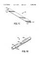
- FIG. 1Cis a perspective view of a label of the type employed in the apparatus of FIG. 1 A;
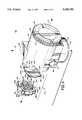
- FIG. 2shows a rear perspective partially cut away view of the selectively pressured housing apparatus of FIG. 1A;
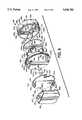
- FIG. 3is a rear perspective exploded view of the selectively pressured housing apparatus of FIG. 1A;
- FIG. 4is a front perspective view, partially exploded, of the selectively pressured housing apparatus of FIG. 1A;
- FIG. 5is a front perspective view, partially broken away, of the selectively pressured housing apparatus of FIG. 1A;
- FIG. 6is a front perspective exploded view of the selectively pressured housing depicted in FIG. 5;
- FIG. 7is an exploded front perspective view of the electronic assemblies of the type depicted in FIG. 6;
- FIG. 8is an exploded rear perspective view of the electronic assemblies of the type depicted in FIG. 6.
- the present inventionis directed to selectively pressured housing apparatus that contain, for example, the process control electronics for a differential pressure transmitter.
- an upper housing according to the inventioncouples to a second lower housing containing, among other components, a pair of process diaphragms and a pressure transducer.
- Each process diaphragmis exposed to one of two fluid pressures that are to be compared, and deflects in response to the pressure of that fluid.
- the transducerresponds to the difference between the two pressures of the process fluids, and produces an electrical output signal that typically is used for controlling fluid flow in process conduits.
- the electrical output signalcan be coupled to the process control electronics by way of a port extending between the two housings.
- Housing apparatuscan further include one or more fittings connected to electrical conduits for coupling processed signals, from the process control electronics, to other electronic equipment, such as process controlling computers located in remote control areas.
- the housing apparatus of the inventionprovide several improvements over the prior art.
- the inventionprovides a housing assembly having multiple selectively pressure sealed chambers. As detailed below, such selectively sealed chambers ensure that process fluids do not inadvertently vent into the electrical conduits, and improve environmental protection of sensitive transmitter electronics.
- the inventionprovides a standard housing that can accommodate a variety of customized circuit modules to provide any of multiple functions at relatively low manufacturing and inventory costs. Additionally, the invention provides improved access to the circuit modules contained in the housing, and controls access to the housing by way of a tamper-proof mechanism.
- FIG. 1Ashows an external perspective view of a differential pressure transmitter 100, including a selectively pressure sealed housing assembly 102 according to the invention.
- the illustrated upper housing assembly 102is mounted on a second or lower housing 104, which contains, among other components, a pair of process diaphragms and a pressure transducer.
- Two process fluids, whose pressures are to be compared,couple to the housing 104 and to the process diaphragms therein by way of fittings 106 and 108.
- the housing assembly 102includes a housing body 110 elongated along a fixst axis 112 and having a collar 114 extending along a second axis 116 transverse to the first axis 112.
- the body 110has a hollow inner chamber.
- the housing assembly 102has removable and replaceable end-caps 118 and 120, threadably mounted to axially opposed open ends 122 and 124.
- Each end-cap 118 and 120has a substantially cylindrical outer surface that is recessed with axially extending groove-like recesses 118a and 120a. The recesses are spaced circumferentially about the outer surface of each end-cap 118 and 120, to form radially-projecting flutes on each end-cap.
- any recess 118a on the end-cap 118can selectively engage a stem 126 to preclude rotation of the end-cap 118, with respect to the housing body 110.
- any recess 120acan selectively engage a stem 128 to preclude rotation of the end-cap 120, with respect to the housing body 110.
- the illustrated stem 126is structured as a cylindrical machine screw with threads 126a, and has a flatted portion 126b axially intermediate cylindrical portions 126c and 126d.
- the illustrated flatted portion 126bis generally cylindrical, in transverse cross section, with a recess along a chord.
- the housing body 110includes a boss 130 having a threaded aperture 132, which extends parallel to the first axis 112.
- the threaded stem 126seats in the correspondingly threaded aperture 132, with the portion 126c protruding axially from the aperture 132 to seat in a recess 118a.
- the flatted portion 120b and other cylindrical portion 126dseat within the threaded aperture 132.
- the housing body 110is apertured at the boss 130 with a hole 134 that passes through the threaded aperture 132.
- the hole 134is located along the portion of the aperture 132 that seats the flatted portion 126b of the stem 126.
- a filament 136such as a lock wire, passes through the hole 134 and engages the flatted portion 126b to preclude rotation and removal of the stem 126.
- the lock wire 136can be fastened with a deformable clasp 138 to preclude inadvertent removal, thereby rendering the end-cap 118 relatively tamper-proof, unless the wire is cut.
- the stem 126With the wire 136 removed, the stem 126 can be rotated and removed from the body, or can be threaded further into the aperture 132 to be clear of the end-cap flutes, to allow the end-cap 118 to be rotatably removed from the body 110.
- the stem 128, at the other end of the housing body,is constructed in the same fashion as the stem 126. Accordingly, the illustrated housing body 110 includes another boss 140 having an axially extending threaded aperture 142.
- the stem 128threadably seats in the aperture 142 and includes a protruding portion that selectively engages and seats in a recess 120a in the end-cap 120.
- a hole 144passes through the aperture 142 to accommodate a lock wire 146, which engages a flatted portion of the stem 128 to preclude inadvertent removal thereof.
- a deformable clasp 147fastens the wire 146 to precludes its unwanted removal.
- the housing assembly 102has a label 148 mounted circumferentially around a recessed outer surface 115 of the collar 114.
- the label 148shown in FIG. 1C, includes a fastening tab 150, which upon installation of the label on the collar 114, fits within a fastening aperture 152, and is folded back to lock the label 148 onto the collar.
- the label 148includes a notch or detent 154, which is formed when the label 148 is fastened.
- the detent 154interlocks with a radial projection 156 on the collar 114 to fix the rotational position of the label 148 on the collar 114.
- the detent 154in combination with the radial projection 156, provides a mechanism by which the legend on the label can be selectively oriented on the collar, without rivets or piercing the housing.
- the illustrated body 110 of the housing apparatus 102has a boss 158 having a through fitting 160 that communicates through the tubular wall of the body to the chamber.
- the fitting 160can connect, with a conventional structure, by means of an electrical conduit (not shown) to couple electrical signals from the electronics within the housing body 110 to, for example, a remote control room.
- the fitting 160is typical of others that can be provided on the body 110; see for example the further boss 159 and fitting 161, illustrated in FIG. 3.
- the housing body 110has a tubular wall 162 that in part defines the chamber therein.
- a wall member 164extends radially inward from the tubular wall 162. It is oriented transverse to the first axis 112 and parallel to the second axis 116.
- the wall member 164divides the hollow chamber into a user termination compartment 166 and an electronics and display compartment 168; the compartments being adjacent along the first axis 112.
- An apeme 170extends through the wall member 164 and hence communicates between the two compartments.
- the aperture 170has a mounting seat 172 circumferentially disposed about it for removably and replaceably seating an electro-mechanical terminal block fitting 174, with a pressure seal or deformable O-ring, to the wall member 164.
- the electro-mechanical terminal-block fitting 174is removable and replaceable from the first compartment 166, by way of the first open end 124.
- the illustrated mounting seat 172projects axially along the first axis 112 into the user termination comparUnent 166 from the wall member 164 to form an annular channel 176 between the axially projecting portion of the mounting seat 172 and the tubular inner wall 162.
- the channel 176extends circumferentially around the mounting seat 172 and provides a storage area for electrical wires coupling signals out of the user termination compartment 166 by way of fittings 160 and/or 161.
- the illustrated mounting seat 172includes a planar surface 178, which faces along axis 112 into the first compartment 166.
- the planar surface 178is axially recessed with an O-ring groove 181.
- a deformable O-ring which seats in groove 181aids in achieving a pressure seal between the terminal-block fitting 174 and the mounting seat 172.
- the mounting seat 172further includes tapped holes 180a-180d for removably and replaceably fastening the electro-mechanical terminal-block fitting 174 to the mounting seat 172 with bolts 198a-198d.
- the terminal-block fitting 174includes a terminal block 182 and a two-sided printed circuit board 184.
- the terminal block 182has a mounting portion with radial projections 186a-186d, each having a corresponding through holes 188a-188d.
- the printed circuit board 184has a mounting portion with radial projections 190a-190d, each also having corresponding through apertures 192a-192d.
- a first side 182a of the terminal block 182includes a set of electrical terminals 194a-194h (FIG. 3) for removable and replaceable connection from the user termination compartment 166 and from conduit fittings 160 and 161.
- the terminals 194a-194helectrically couple from the first side 182a of the terminal block 182 to a corresponding set of solderable terminals 196 on the opposed second side 182b of the terminal block 182.
- the through holes 188a-188d of the terminal block 182are aligned with the through apertures 192a-192d of the circuit board 184, and the first side 184a of the printed circuit board 184 is affixed to and seated flush with the second side 182b of the terminal block 182.
- Electrical conductors on the circuit boardare electrically coupled to the terminals 194a-194h by way of the solderable terminals 196.
- the terminalsare soldered to the board in a manner that closes any pre-existing through holes in order that the board forms a seal barrier.
- terminals 194a-194hare blind holes so that the terminal block 182 also forms a seal.
- each through aperture 188a-188d and 192a-192daxially aligns with a corresponding tapped mounting hole 180a-180d, and the terminal-block fitting 174 is secured in place by mounting bolts 198a-198d.
- the fitting 174 with the mounting seat 172forms a pressure seal between compartments 166 and 168.
- This pressure sealis to isolate humidity or fluid present in compartment 166 from entering and damaging electronics in compartment 168, shown in FIG. 6.
- second side 184b of the circuit board 184includes a set of electrical terminals 200 for removable and replaceable connection with process control electronics, contained in the electronics and display compartment 168, by way of the aperture 170.
- the circuit board 184also includes EMI and RFI protection circuitry.
- EMI and RFI protection circuitryAccording to one embodiment of the invention, a plurality of different circuit boards 184 and termination blocks 182, each having customized electrical functionality, can be employed interchangeably in the housing apparatus 102.
- circuit board 184can be adapted to couple various types of conditioned signals to terminals 194a-194h, such as digital signals or analog signals, in either optical or electrical form.
- terminal blocks 182each having customized terminal configurations, can be selected for employment in the fitting 174, depending in part on the particular circuitry contained on the circuit board 184.
- the terminals 194a-194fcan be adapted as screw-type fittings, coaxial cable connections, fiber optical connections, and/or banana jack type connections. Additionally, those connections may or may not be powered, and can provide digital or analog outputs.
- the terminal-block fitting 174maintains a consistent sealing function and mechanical outline.
- a common housing body 110can be employed, regardless of the selected features of terminal-block fitting 174, thereby reducing inventory and manufacturing costs.
- the electronics and display compartment 168(FIG. 6) of the housing body 110 is adapted for removably and replaceably seating first and second axially successive circuit modules 202 and 204, respectively, by way of the second open end 122.
- the second compartment 168is partially defined by an tubular wall 162.
- the wall 162has a threaded portion 208 (FIG. 6) for threadably engaging the end-cap 118.
- the electronics and display compartment 168also has a mounting portion for removably and replaceably mounting the two axially successive circuit modules 202 and 204.
- the illustrated mounting portionincludes a finished, relatively smooth cylindrical section 210, axially adjacent to the threaded portion 208 and extending into compartment 168 along the wall 162.
- the mounting portion 210further includes, at its axially innermost terminal end, a small shoulder 212 radially extending inward.
- Mounting threadscomprising two threaded holes 214 and 216, axially extend into diametrically opposed bosses 218 and 220, which radially extend inward from the wall 162.
- the bosses 218 and 220have planer surfaces 218a and 220a, respectively, facing along axis 112 into the compartment 168.
- the first circuit module 202 of the illustrated embodimenthas a mounting bracket 222, two circuit boards 224 and 226, and a receptacle 228.
- the circuit board 226mounts inside receptacle 228, which can be filled with a potting material to further seal electrical components on the circuit board 226, thus additionally protecting those components from environmental adversities, such as humidity.
- the mounting bracket 222removably and replaceably seats the circuit board 224, the circuit board 226, and the receptacle 228.
- the mounting bracket 222is constructed from an electrically insulative, flexible plastic. As shown in detail in FIGS.
- the bracket 222has a first side 222a from which three axial projections 230a-230c, equally spaced around its periphery, extend along an axis normal to that side.
- Axial projections 230b and -230ceach includes two radially inward facing slots 232a and 232b, which seat circuit boards.
- Through apertures 234a and 234bare used in lieu of slots.
- a tab 236 on the circuit board 224matingly interfits with the through aperture 234b, while the edge of the board 224 matingly interfits with the slot 232b on each axial projection 230a-230c.
- aperture 234amatingly receives a tab 238 on the circuit board 226.
- Radial projections 228a and 228b on the potting receptacle 228matingly interfit with the slots 232a of axial projections 230b and 230c, respectively.
- the bracket 222secures the circuit boards 224 and 226, and the potting receptacle 228, with a removable and replaceable mounting. If potting is not required, two printed wiring assemblies can, where desired, be accommodated in place of the potting receptacle 228 and circuit board 226.
- the mounting bracket 222includes a collar 240 extending circumferentially around and axially from an opposed second side 222b.
- the collar 240includes four mounting notches 241a-241d for optionally, matingly mounting the second axially successive circuit module 204.
- Each mounting notch 241a-241dincludes an axially extending portion 243 and a circumferentially extending portion 245, shown in FIG. 6.
- the outer wall of the collar 240seats a deformable O-ring 242 circumferentially disposed around it.
- the bracket 202is apertured with two diametrically opposed through holes 244a and 244b.
- the surface 222ahas two mounting pads 246a and 246b.
- Mounting pad 246ais a flat finished surface that is circumferentially disposed about aperture 244a.
- mounting pad 246bis a flat finished surface that is circumferentially disposed about aperture 244b.
- the surface 222bfaces toward the open end 122 and is normal to the first axis 112.
- Each through aperture 244a and 244baxially aligns with one threaded aperture 214 and 216, shown in FIG. 6.
- the module 202telescopically interfits into the housing body 110 so that mounting pads 246a and 246b seat flush on the planar surfaces 218a and 220a, respectively.
- Threaded mounting bolts 248 and 250pass through the apertures 244a and 244b to engage matingly threaded holes 214 and 216, respectively, to secure the module 202 to the housing body 110.
- the circuit board 224includes notches 252a and 252b to enable the mounting bolts 248 and 250 to pass, unobstructed.
- a pressure sealis formed between planar surface 218a and mounting pad 246a, and between planer surface 220a and mounting pad 246b, forming in combination with O-ring 242 a sealed protected space for electrical circuit boards 224 and 226.
- the O-ring 242forms a pressure seal with the finished portion 210 oft he tubular wall 162.
- the installed element 202further subdivides the electronics and display compartment 168 into first and second cavities 256 and 258.
- the first cavity 256extends axially from the wall member 164 to the O-ring 242, and contains the circuit boards 224 and 226 and the potting receptacle 228.
- the second cavity 258extends axially from the O-ring 242 to end 122 of the housing body 110.
- One advantage of this configurationis that the end-cap 118 can be removed, without exposing the electronics of the module 202 to any adverse environmental conditions, such as, humidity. Therefore, optionally, one or both of the circuit boards 224 and 226 can be constructed without additional moisture-sealing material to protect the circuitry contained on those boards.
- the surface 222b of bracket 222includes two ribbed axial projections 260a and 260b for a technician to grasp onto, when removing module 202 from compartment 168. These projections provide opposed and spaced-apart surfaces for manual engagement from the open end 122 of the housing body 110.
- a vacuumcan develop in the first cavity 256, relative to the second cavity 258. If such a vacuum forms, even the finger grips 260a and 260b can prove insufficient to remove the module 202.
- the pressure seal between the planar surfaces 218a and 220a and the mounting pads 246a and 246bis broken, thereby, releasing any vacuum so formed.
- process fluidsmay after an extended period of time vent into the cavity 256, shown in FIG. 2.
- the pressure seal between cavities 256 and 258is selected to be substantially less than the pressure seal between the terminal-block fitting 174 and the mounting seat 172.
- the seal between the terminal-block fitting 174 and the mounting seat 172can withstand pressures of upwards of 800 psi, while the seal between cavity 256 and cavity 258 can only withstand pressures of about 3-5 psi.
- the sealformed by end cap 118, between cavity 258 and the external atmosphere, can only withstand pressures of approximately 400 psi. Consequently, any such gases which vent into cavities 256 and 258 would vent to the atmosphere, rather than entering the conduits. Thus, if process fluid inadvertently vents into the first cavity 256, the fluid vents into the second cavity 258, and then to atmosphere and does not rupture the seal between the terminal-block fitting 174 and the mounting seat 172.
- the circuit boards 224 and 226, and the bracket 222 which mounts themhave a plurality of electrical terminals for removable and replaceable connection.
- the circuit board 224has a first electrical connector 260 on the side 224a and has a set of associated electrical terminals 260a that axially project from the opposite side 224b.
- the circuit board 224has a second electrical connector 262, mounted adjacent to connector 260 on side 224a, that also has a set of associated electrical terminals 262a that axially project from side 224b.
- the terminals 260a and 262aare adapted for removable and replaceable electrical connection to other electrical devices, namely to a differential pressure transducer in the illustrated embodiment.
- the circuit board 224further includes a third connector 264 mounted on side 224a.
- the connector 264removably and replaceably connects directly to a connector 266, which is mounted on side 222a of the bracket 222.
- the connector 264couples electrical signals through the bracket 222 to a connector 268 mounted on the bracket side 222b.
- the circuit board 224has two additional electrical connectors 270 and 272 mounted on side 224b.
- the connector 270is adapted for removable and replaceable direct connection to a mating electrical connector 274 on side 226a of the circuit board 226.
- the connector 272is adapted for a removable and replaceable ribbon wire (not shown) connection to a reed switch connection positioned in the port chamber of the housing assembly 276 (FIG. 2).
- the circuit board 224performs signal processing, while the circuit board 226 provides power to the circuit board 224. More specifically, the illustrated circuit board 224 receives electrical signals, which are indicative of a pressure difference between two process fluids, from a pressure transducer by way of the terminals 260a and 262a. The circuit board 224 performs an analog-to-digital conversion on the received signals. It then digitally processes the converted signals to compensate for nonlinearity and temperature-related errors in the signals from the pressure transducer. The circuit board 224 formats the processed signals for digital transmission, and couples those digital signals to board 226 by way of connectors 270 and 274.
- Board 226 in tamcouples the signals to the electrical terminal-block fitting 174, by way of a connector 267 on side 226b of the circuit board 226 and the terminals 200 on the terminal-block fitting 174.
- the circuit board 224can also couple the processed digital signals into the cavity 258, by way of the connectors 264 on the circuit board 224 and the connectors 266 and 268 on the bracket 222.
- the circuit board 226also performs a digital-to-analog conversion on the processed signals, and provides the processed signals, in analog form, to the electrical terminal-block fitting 174.
- the sealed housing electronics assembly 102includes an electrical display module 204 that operates in conjunction with the circuit module 202.
- the illustrated display module 204has a bracket 280, a circuit board 282, and a display element 284.
- the display bracket 280is shaped generally like a circular lid and has opposed sides 280a and 280b, with a rectangular aperture 281 therebetween.
- a rectangular bezel-like frame 286extends around the periphery of the rectangular apeme 281 and projects axially from both side 280a and 280b.
- the display element 284which can, for example, be a liquid crystal display, seats in the aperture 281 within the bezel-like frame 286, and is readable from side 280a by way of the rectangular aperture 281.
- the display element 284includes two horizontally extending rows 290 and 292 of electrical contacts. Each row of electrical contacts 290 and 292 provides addressable interconnections to a plurality of display segments in the display element 284.
- the side 282a of the circuit board 282has two rows 294 and 296 of correspondingly arranged electrical contacts for coupling electrical control signals to the display element 284 by way of the rows 290 and 292 of contacts, respectively.
- the display bracket 280has a peripheral rim-like collar 298 extending axially from and circumferentially around the surface 280b.
- the circuit board 282seats within the collar 298.
- Flexible conductors 300 and 302, shown in FIG. 7,mount between side 282a of the circuit board 282 and the display element 284.
- Each flexible conductor 300 and 302has a plurality of electrically conductive filaments passing through it between its opposed sides 300a and 300b, and 302a and 302b, respectively.
- the flexible conductors 300 and 302matingly sandwich between side 282a of the circuit board 282 and the display element 284.
- the side 300a of the flexible conductor 300couples to the contact row 296 of the circuit board 282.
- the side 300bcouples to the contact row 290 of the display 284. In this way, the flexible conductors couple electrical control signals between the rows of contacts on the circuit board 282 and the rows of contacts on the display element 284.
- the illustrated circuit board 282has four through apertures 304a-304d for mounting to the display bracket 280.
- the through apertures 304a-304daxially align with axially extending threaded mounting apertures 306a-306d in the bezel-like frame 288.
- Mounting screws 308a-308dengage the threaded apertures 306a-306d to fasten the circuit board 282 in place to compress the flexible conductors to ensure secure and reliable electrical connection between the circuit board 282 and the display element 284.
- the circuit board 282has two push button switches 310 and 312 mounted on side 282a.
- the two push button switches 310 and 312couple through apertures 315 and 317, respectively, in the bracket 280 and are accessible from the end 122 of housing 110.
- Gaskets 314 and 316provides a pressure seal between the push button switches 310 and 312 and the frame 288.
- the circuit board 282further includes an electrical connector 283 for removably and replaceably connecting with a feedthrough connector 268 on the bracket 222 of the circuit module 202.
- the collar 298 of the display bracket 280includes four circumferentially equally-spaced radial projections 318a-318d, for mounting the display module 204 to notches in the collar 240 of bracket 222.
- each radial projection 318a-318dinterfits with an axially extending notch portion 245, shown in FIG. 6, of a corresponding mounting notch 241a-241d.
- the element 204can then be rotated clockwise so that each radial projection 318a-318d engages a circumferentially extending portion 243 of the corresponding mounting notch 241a-241d.
- the display module 204mounts, removably and replaceably, to and interlocks with circuit module 202.
- the display module 204can mount in any one of four rotational orientations with respect to the element 202 so that display element 284 is readable, regardless of the rotational orientation of the housing body 110. This is possible since circuit board assembly 204 is connected to circuit assembly 202 by a flexible ribbon connector (not shown).
- the collar 298 of the display bracketseats a deformable O-ring 320 circumferentially disposed there around.
- the collar 298telescopically fits into the collar 240, with O-ring 320 forming a pressure seal with the inner wall of collar 240.
- the sealthus formed, environmentally isolates the electronics of circuit module 202 and display module 204. Consequently, the end-cap 118 can be removed and the push buttons 310 and 312 accessed, without exposing any circuitry contained in that compartment to adverse environmental conditions, such as excessive moisture.
- two ribbed manually-engageable tabs 322 and 324axially project from the surface 280a for a technician to grasp when removing, and when installing, the display module 204.
- the display module 204preferably includes a power supply and signal processing circuitry, previously discussed, and the circuit board 282 of the display module 204 contains circuitry for controlling and interfacing with the display element 284, and with the push button switches 314 and 316. In applications that do not require both modules, the display module 204 is used alone.
- the circuit board 282then additionally includes the signal processing and the power supply circuitry, in lieu of the circuit boards 224 and 226.
- the display module 204can, nevertheless, utilize a bracket of similar construction to the circuit-board bracket 240 to provide selected rotational orientations.
- the circuit-board bracketneed not include structures, such as the axial projections 230a-230c, for mounting additional circuit boards.
- the circuitry for providing processed signals to the terminal-block fitting 184 in digital formatis omitted. In this way, the invention provides a plurality of interchangeable circuit modules and display modules, which can be utilized in a plurality of combinations to provide a variety of selectable electrical features.
- the push button switches 310 and 312operate in essentially the same manner to enable a technician to perform various diagnostic and/or calibration functions.
- these switchescan enable a technician to calibrate the electrical elements and the pressure transducer with regard to a pressure reference; alternate functions are to zero the system, initialize the electronics, and to adjust the pressure span over which the display element 284 operates.
- the end cap 118is constructed with a transparent window 326 for providing visual access to the display element 284.
- the window 326is seated with a selected radial pressure seal to a shoulder 328 on the end cap 118, by way of a deformable O-ring 330.
- a ring clamp 332is compressed into a slot 334 to fasten the glass in place, with the selected pressure seal.
Landscapes
- Physics & Mathematics (AREA)
- General Physics & Mathematics (AREA)
- Measuring Fluid Pressure (AREA)
- Diaphragms And Bellows (AREA)
- Casings For Electric Apparatus (AREA)
- External Artificial Organs (AREA)
- Connector Housings Or Holding Contact Members (AREA)
Abstract
Description
Claims (47)
Priority Applications (11)
| Application Number | Priority Date | Filing Date | Title |
|---|---|---|---|
| US08/449,104US5656782A (en) | 1994-12-06 | 1995-05-24 | Pressure sealed housing apparatus and methods |
| RU97121578/28ARU2181880C2 (en) | 1995-05-24 | 1996-05-20 | Gear to position electric elements with differentiated tightness of compartments |
| KR1019970708294AKR100436969B1 (en) | 1995-05-24 | 1996-05-20 | Selectively pressure sealed housing apparatus for electrical elements |
| AT96920312TATE207612T1 (en) | 1995-05-24 | 1996-05-20 | PRESSURE TIGHT HOUSING ARRANGEMENT |
| BR9609121ABR9609121A (en) | 1995-05-24 | 1996-05-20 | Pressure-sealed housing apparatus and methods |
| EP96920312AEP0829004B1 (en) | 1995-05-24 | 1996-05-20 | Pressure sealed housing apparatus |
| JP53578996AJP3920335B2 (en) | 1995-05-24 | 1996-05-20 | Housing structure for process fluid control electronics |
| CN96195769.7ACN1106570C (en) | 1995-05-24 | 1996-05-20 | Pressure sealed housing apparatus and methods |
| CA002220961ACA2220961C (en) | 1995-05-24 | 1996-05-20 | Pressure sealed housing apparatus and methods |
| PCT/US1996/007279WO1996037764A1 (en) | 1995-05-24 | 1996-05-20 | Pressure sealed housing apparatus and methods |
| DE69616314TDE69616314T2 (en) | 1995-05-24 | 1996-05-20 | PRESSURE-TIGHT HOUSING |
Applications Claiming Priority (2)
| Application Number | Priority Date | Filing Date | Title |
|---|---|---|---|
| US29/032,041USD366000S (en) | 1994-12-06 | 1994-12-06 | Pressure transmitter housing |
| US08/449,104US5656782A (en) | 1994-12-06 | 1995-05-24 | Pressure sealed housing apparatus and methods |
Related Parent Applications (1)
| Application Number | Title | Priority Date | Filing Date |
|---|---|---|---|
| US29032041Continuation-In-Part | 1994-12-06 |
Publications (1)
| Publication Number | Publication Date |
|---|---|
| US5656782Atrue US5656782A (en) | 1997-08-12 |
Family
ID=23782876
Family Applications (1)
| Application Number | Title | Priority Date | Filing Date |
|---|---|---|---|
| US08/449,104Expired - LifetimeUS5656782A (en) | 1994-12-06 | 1995-05-24 | Pressure sealed housing apparatus and methods |
Country Status (11)
| Country | Link |
|---|---|
| US (1) | US5656782A (en) |
| EP (1) | EP0829004B1 (en) |
| JP (1) | JP3920335B2 (en) |
| KR (1) | KR100436969B1 (en) |
| CN (1) | CN1106570C (en) |
| AT (1) | ATE207612T1 (en) |
| BR (1) | BR9609121A (en) |
| CA (1) | CA2220961C (en) |
| DE (1) | DE69616314T2 (en) |
| RU (1) | RU2181880C2 (en) |
| WO (1) | WO1996037764A1 (en) |
Cited By (72)
| Publication number | Priority date | Publication date | Assignee | Title |
|---|---|---|---|---|
| US5798910A (en)* | 1996-08-29 | 1998-08-25 | Caloritech Inc. | Sealable housing for electrical components |
| WO1999028718A1 (en)* | 1997-12-02 | 1999-06-10 | Fluoroware, Inc. | Fluid monitoring device |
| US5942691A (en)* | 1998-07-22 | 1999-08-24 | Delco Electronics Corp. | Differential pressure transducer assembly |
| USD439178S1 (en) | 2000-03-21 | 2001-03-20 | Rosemount Inc. | Pressure transmitter with dual inlet base and single compartment housing |
| USD439177S1 (en) | 2000-03-21 | 2001-03-20 | Rosemount Inc. | Pressure transmitter with single inlet base and economy housing |
| USD439180S1 (en) | 2000-03-21 | 2001-03-20 | Rosemount Inc. | Pressure transmitter with single inlet base and single compartment housing |
| USD439179S1 (en) | 2000-03-21 | 2001-03-20 | Rosemount Inc. | Pressure transmitter with single inlet base and dual compartment housing |
| USD439181S1 (en) | 2000-03-21 | 2001-03-20 | Rosemount Inc. | Pressure transmitter with dual inlet base and dual compartment housing |
| USD441672S1 (en) | 2000-03-21 | 2001-05-08 | Rosemount Inc. | Pressure transmitter with dual inlet base and economy housing |
| US6422532B1 (en)* | 2000-03-01 | 2002-07-23 | Invensys Systems, Inc. | Severe service valve positioner |
| US6457367B1 (en) | 1999-09-28 | 2002-10-01 | Rosemount Inc. | Scalable process transmitter |
| US6480131B1 (en) | 2000-08-10 | 2002-11-12 | Rosemount Inc. | Multiple die industrial process control transmitter |
| US6487912B1 (en) | 1999-09-28 | 2002-12-03 | Rosemount Inc. | Preinstallation of a pressure sensor module |
| US6504489B1 (en) | 2000-05-15 | 2003-01-07 | Rosemount Inc. | Process control transmitter having an externally accessible DC circuit common |
| US6511337B1 (en) | 1999-09-28 | 2003-01-28 | Rosemount Inc. | Environmentally sealed instrument loop adapter |
| US6510740B1 (en) | 1999-09-28 | 2003-01-28 | Rosemount Inc. | Thermal management in a pressure transmitter |
| US6516672B2 (en) | 2001-05-21 | 2003-02-11 | Rosemount Inc. | Sigma-delta analog to digital converter for capacitive pressure sensor and process transmitter |
| USD471829S1 (en) | 2001-10-11 | 2003-03-18 | Rosemount Inc. | Dual inlet base pressure instrument |
| US20030056603A1 (en)* | 2001-09-27 | 2003-03-27 | Civetta Massimo | Differential pressure transmitter with simplified structure |
| USD472831S1 (en) | 2001-10-11 | 2003-04-08 | Rosemount Inc. | Single inlet base pressure instrument |
| US6546805B2 (en) | 2000-03-07 | 2003-04-15 | Rosemount Inc. | Process fluid transmitter with an environmentally sealed service block |
| US6571132B1 (en) | 1999-09-28 | 2003-05-27 | Rosemount Inc. | Component type adaptation in a transducer assembly |
| US6662662B1 (en) | 2000-05-04 | 2003-12-16 | Rosemount, Inc. | Pressure transmitter with improved isolator system |
| US6684711B2 (en) | 2001-08-23 | 2004-02-03 | Rosemount Inc. | Three-phase excitation circuit for compensated capacitor industrial process control transmitters |
| US20040046722A1 (en)* | 2002-09-06 | 2004-03-11 | Trimble Steven R. | Low power physical layer for a bus in an industrial transmitter |
| US6765968B1 (en) | 1999-09-28 | 2004-07-20 | Rosemount Inc. | Process transmitter with local databus |
| US20040154404A1 (en)* | 2001-05-18 | 2004-08-12 | Robert Parravicini | Pressure transmitter |
| US20040203421A1 (en)* | 2002-04-22 | 2004-10-14 | Hedtke Robert C. | Process transmitter with wireless communication link |
| US20050056106A1 (en)* | 1999-09-28 | 2005-03-17 | Nelson Scott D. | Display for process transmitter |
| US20050060980A1 (en)* | 1994-06-30 | 2005-03-24 | E.I. Du Pont De Nemours And Company | Process for making poly(trimethyleneterephthalate) bulked continuous filaments, the filaments thereof and carpets made therefrom |
| US20050289276A1 (en)* | 2004-06-28 | 2005-12-29 | Karschnia Robert J | Process field device with radio frequency communication |
| US20050284227A1 (en)* | 2004-06-25 | 2005-12-29 | Broden David A | High temperature pressure transmitter assembly |
| US20060148410A1 (en)* | 2005-01-03 | 2006-07-06 | Nelson Richard L | Wireless process field device diagnostics |
| US20070191970A1 (en)* | 2006-01-30 | 2007-08-16 | Orth Kelly M | Transmitter with removable local operator interface |
| US20080083446A1 (en)* | 2005-03-02 | 2008-04-10 | Swapan Chakraborty | Pipeline thermoelectric generator assembly |
| US20080083445A1 (en)* | 2006-09-28 | 2008-04-10 | Swapan Chakraborty | Thermoelectric generator assembly for field process devices |
| US20090025486A1 (en)* | 2007-07-27 | 2009-01-29 | Alain Cros | Static fluid meter |
| US20100148105A1 (en)* | 2008-07-09 | 2010-06-17 | Christopher Reckker | Security mechanism for a flow control device on a railcar and method of coupling the same |
| US7773715B2 (en) | 2002-09-06 | 2010-08-10 | Rosemount Inc. | Two wire transmitter with isolated can output |
| US7913566B2 (en) | 2006-05-23 | 2011-03-29 | Rosemount Inc. | Industrial process device utilizing magnetic induction |
| US7957708B2 (en) | 2004-03-02 | 2011-06-07 | Rosemount Inc. | Process device with improved power generation |
| US7977924B2 (en) | 2008-11-03 | 2011-07-12 | Rosemount Inc. | Industrial process power scavenging device and method of deriving process device power from an industrial process |
| US8049361B2 (en) | 2008-06-17 | 2011-11-01 | Rosemount Inc. | RF adapter for field device with loop current bypass |
| WO2011160949A1 (en)* | 2010-06-21 | 2011-12-29 | Endress+Hauser Flowtec Ag | Electronics housing for an electronic device and device formed therewith |
| US8145180B2 (en) | 2004-05-21 | 2012-03-27 | Rosemount Inc. | Power generation for process devices |
| US8160535B2 (en) | 2004-06-28 | 2012-04-17 | Rosemount Inc. | RF adapter for field device |
| US8250924B2 (en) | 2008-04-22 | 2012-08-28 | Rosemount Inc. | Industrial process device utilizing piezoelectric transducer |
| US8334788B2 (en) | 2010-03-04 | 2012-12-18 | Rosemount Inc. | Process variable transmitter with display |
| US20130104663A1 (en)* | 2011-10-31 | 2013-05-02 | Robert C. Hedtke | Coplanar process fluid pressure sensor module |
| US8452255B2 (en) | 2005-06-27 | 2013-05-28 | Rosemount Inc. | Field device with dynamically adjustable power consumption radio frequency communication |
| US8538560B2 (en) | 2004-04-29 | 2013-09-17 | Rosemount Inc. | Wireless power and communication unit for process field devices |
| US8626087B2 (en) | 2009-06-16 | 2014-01-07 | Rosemount Inc. | Wire harness for field devices used in a hazardous locations |
| US8694060B2 (en) | 2008-06-17 | 2014-04-08 | Rosemount Inc. | Form factor and electromagnetic interference protection for process device wireless adapters |
| US8787848B2 (en) | 2004-06-28 | 2014-07-22 | Rosemount Inc. | RF adapter for field device with low voltage intrinsic safety clamping |
| US8847571B2 (en) | 2008-06-17 | 2014-09-30 | Rosemount Inc. | RF adapter for field device with variable voltage drop |
| CN104081167A (en)* | 2011-12-14 | 2014-10-01 | 恩德斯+豪斯流量技术股份有限公司 | Housing cover for an electronics housing and electronics housing formed therewith |
| US8929948B2 (en) | 2008-06-17 | 2015-01-06 | Rosemount Inc. | Wireless communication adapter for field devices |
| US20150085449A1 (en)* | 2013-09-25 | 2015-03-26 | Rosemount Inc. | Industrial process fluid device with humidity-sealed electronics module |
| WO2015042929A1 (en) | 2013-09-30 | 2015-04-02 | Rosemount Inc | Process variable transmitter with dual compartment housing |
| US9048901B2 (en) | 2013-03-15 | 2015-06-02 | Rosemount Inc. | Wireless interface within transmitter |
| US9310794B2 (en) | 2011-10-27 | 2016-04-12 | Rosemount Inc. | Power supply for industrial process field device |
| US9479201B2 (en) | 2014-03-26 | 2016-10-25 | Rosemount Inc. | Process variable transmitter with removable terminal block |
| US9615469B2 (en) | 2012-12-20 | 2017-04-04 | Continental Teves Ag & Co. Ohg | Electronic device and method for producing an electronic device |
| US9674976B2 (en) | 2009-06-16 | 2017-06-06 | Rosemount Inc. | Wireless process communication adapter with improved encapsulation |
| US10015899B2 (en) | 2015-06-29 | 2018-07-03 | Rosemount Inc. | Terminal block with sealed interconnect system |
| US10663931B2 (en) | 2013-09-24 | 2020-05-26 | Rosemount Inc. | Process variable transmitter with dual compartment housing |
| US10701820B1 (en)* | 2019-06-06 | 2020-06-30 | Fisher Controls International Llc | Tamper proof approaches for securing an enclosure |
| US10761524B2 (en) | 2010-08-12 | 2020-09-01 | Rosemount Inc. | Wireless adapter with process diagnostics |
| US11513018B2 (en)* | 2020-09-30 | 2022-11-29 | Rosemount Inc. | Field device housing assembly |
| USD1046782S1 (en)* | 2021-01-12 | 2024-10-15 | Micro Motion, Inc. | Electronic housing |
| US12218775B2 (en) | 2022-12-19 | 2025-02-04 | Rosemount Inc. | Advanced physical layer (APL) adapter for legacy field devices |
| USD1063846S1 (en)* | 2021-01-12 | 2025-02-25 | Micro Motion, Inc. | Electronics housing for a flowmeter |
Families Citing this family (18)
| Publication number | Priority date | Publication date | Assignee | Title |
|---|---|---|---|---|
| DE29615534U1 (en)* | 1996-09-06 | 1996-10-24 | Dbt Gmbh | Pressure transducer for measuring hydraulic pressures, especially for mining applications |
| RU2300178C1 (en)* | 2005-12-21 | 2007-05-27 | Федеральное Государственное Унитарное Предприятие "Санкт-Петербургское Морское Бюро Машиностроения "Малахит" | Waterproof housing for shielding electrical instruments |
| EP1989746B1 (en)* | 2006-02-21 | 2011-01-26 | Rosemount, Inc. | Industrial process field device with energy limited battery assembly |
| DE102007052395B4 (en)* | 2007-10-31 | 2009-09-10 | Kg Transmitter Components Gmbh | Pressure transmitter, method for monitoring the condition of a pressure transducer and pressure sensor |
| EP2105716B1 (en)* | 2008-03-28 | 2016-12-28 | VEGA Grieshaber KG | Protective casing with a housing for protecting a measuring device and method of mouting a protective casing |
| DE102008054991A1 (en)* | 2008-12-19 | 2010-06-24 | Endress + Hauser Gmbh + Co. Kg | Differential |
| US7984652B2 (en)* | 2009-09-08 | 2011-07-26 | Rosemount Inc. | Clad industrial process transmitter housing with chassis |
| DE102010001075A1 (en)* | 2010-01-21 | 2011-07-28 | Robert Bosch GmbH, 70469 | Sensor i.e. low pressure sensor, for customer- and/or application-specific variants identical design of mechanical and electrical interfaces, has planar adhesive gasket sealing three chambers against each other in housing portion |
| DE102012006422B4 (en)* | 2012-03-30 | 2015-05-28 | Krohne Messtechnik Gmbh | Meter housing with lens |
| DE102014202354A1 (en)* | 2014-02-10 | 2015-08-13 | Zf Friedrichshafen Ag | Sealing device for a sensor housing |
| US9583901B2 (en)* | 2014-09-30 | 2017-02-28 | Rosemount Inc. | Field device using a seal board assembly |
| US9638600B2 (en)* | 2014-09-30 | 2017-05-02 | Rosemount Inc. | Electrical interconnect for pressure sensor in a process variable transmitter |
| CN104990572A (en)* | 2015-06-26 | 2015-10-21 | 中国石油化工股份有限公司胜利油田分公司 | Special integrated temperature and pressure transmitter for oil well |
| JP2017037040A (en)* | 2015-08-13 | 2017-02-16 | 富士電機株式会社 | Semiconductor physical quantity sensor device and method for manufacturing semiconductor physical quantity sensor device |
| DE102018002977A1 (en)* | 2017-05-11 | 2018-11-15 | Wika Alexander Wiegand Se & Co. Kg | gauge |
| CN109839244B (en)* | 2019-01-02 | 2020-08-25 | 天长市九星仪表有限公司 | Pressure instrument shell with solar panel seat |
| RU200534U1 (en)* | 2019-07-04 | 2020-10-28 | Общество с ограниченной ответственностью "Управление по подготовке технологической жидкости для поддержания пластового давления" | Protective cover for pressure gauge |
| US20240210229A1 (en)* | 2021-01-12 | 2024-06-27 | Micro Motion, Inc. | Interface with improved accessibility |
Citations (20)
| Publication number | Priority date | Publication date | Assignee | Title |
|---|---|---|---|---|
| US3247719A (en)* | 1963-10-01 | 1966-04-26 | Chelner Herbert | Strain decoupled transducer |
| US3869920A (en)* | 1973-04-13 | 1975-03-11 | Yokogawa Electric Works Ltd | Symmetrically arranged, deflection type differential pressure transmitters for controlling industrial systems and processes |
| US4085620A (en)* | 1975-09-30 | 1978-04-25 | Tokyo Shibaura Electric Co., Ltd. | Pressure-electric transducers |
| US4172388A (en)* | 1978-03-09 | 1979-10-30 | American Chain & Cable Company, Inc. | Differential pressure sensor with dual level overrange protection |
| US4176557A (en)* | 1976-06-07 | 1979-12-04 | Bunker Ramo Corporation | Pressure sensor |
| US4414851A (en)* | 1981-08-28 | 1983-11-15 | Motorola, Inc. | Gauge pressure sensor |
| US4466290A (en)* | 1981-11-27 | 1984-08-21 | Rosemount Inc. | Apparatus for conveying fluid pressures to a differential pressure transducer |
| US4653330A (en)* | 1985-07-15 | 1987-03-31 | Rosemount Inc. | Pressure transmitter housing |
| US4748852A (en)* | 1986-10-10 | 1988-06-07 | Rosemount Inc. | Transmitter with an improved span adjustment |
| US4760859A (en)* | 1987-05-18 | 1988-08-02 | Rosemount Inc. | Modular pressure instrument |
| US4833922A (en)* | 1987-06-01 | 1989-05-30 | Rosemount Inc. | Modular transmitter |
| US4958938A (en)* | 1989-06-05 | 1990-09-25 | Rosemount Inc. | Temperature transmitter with integral secondary seal |
| US4986126A (en)* | 1990-03-26 | 1991-01-22 | Acustar, Inc. | Transducer with heat sink |
| US5014557A (en)* | 1990-06-06 | 1991-05-14 | Acustar, Inc. | Composite base for a pressure transducer |
| US5179488A (en)* | 1990-07-26 | 1993-01-12 | Rosemount Inc. | Process control instrument with loop overcurrent circuit |
| WO1993021506A1 (en)* | 1992-04-14 | 1993-10-28 | Rosemount, Inc. | Modular transmitter with flame arresting header |
| US5278543A (en)* | 1987-10-22 | 1994-01-11 | Rosemount Inc. | Transmitter with magnetic zero/span actuator |
| US5353289A (en)* | 1990-10-31 | 1994-10-04 | Nec Corporation | Fault judging device comprising a compression circuit for compressing output pattern signals of a circuit model |
| US5351510A (en)* | 1992-11-13 | 1994-10-04 | Elsag International B.V. | Cover lock for pressure transmitter |
| US5353200A (en)* | 1993-02-24 | 1994-10-04 | Rosemount Inc. | Process transmitter with inner conductive cover for EMI shielding |
Family Cites Families (2)
| Publication number | Priority date | Publication date | Assignee | Title |
|---|---|---|---|---|
| US5666295A (en)* | 1996-01-05 | 1997-09-09 | Sentek Products | Apparatus and method for dynamic weighing of loads in hydraulically operated lifts |
| RU2082956C1 (en)* | 1996-10-08 | 1997-06-27 | Товарищество с ограниченной ответственностью "Модем-095" | Case of measuring pickup |
- 1995
- 1995-05-24USUS08/449,104patent/US5656782A/ennot_activeExpired - Lifetime
- 1996
- 1996-05-20CNCN96195769.7Apatent/CN1106570C/ennot_activeExpired - Fee Related
- 1996-05-20BRBR9609121Apatent/BR9609121A/ennot_activeIP Right Cessation
- 1996-05-20ATAT96920312Tpatent/ATE207612T1/ennot_activeIP Right Cessation
- 1996-05-20CACA002220961Apatent/CA2220961C/ennot_activeExpired - Fee Related
- 1996-05-20EPEP96920312Apatent/EP0829004B1/ennot_activeExpired - Lifetime
- 1996-05-20WOPCT/US1996/007279patent/WO1996037764A1/enactiveIP Right Grant
- 1996-05-20DEDE69616314Tpatent/DE69616314T2/ennot_activeExpired - Lifetime
- 1996-05-20JPJP53578996Apatent/JP3920335B2/ennot_activeExpired - Lifetime
- 1996-05-20KRKR1019970708294Apatent/KR100436969B1/ennot_activeExpired - Lifetime
- 1996-05-20RURU97121578/28Apatent/RU2181880C2/enactive
Patent Citations (21)
| Publication number | Priority date | Publication date | Assignee | Title |
|---|---|---|---|---|
| US3247719A (en)* | 1963-10-01 | 1966-04-26 | Chelner Herbert | Strain decoupled transducer |
| US3869920A (en)* | 1973-04-13 | 1975-03-11 | Yokogawa Electric Works Ltd | Symmetrically arranged, deflection type differential pressure transmitters for controlling industrial systems and processes |
| US4085620A (en)* | 1975-09-30 | 1978-04-25 | Tokyo Shibaura Electric Co., Ltd. | Pressure-electric transducers |
| US4176557A (en)* | 1976-06-07 | 1979-12-04 | Bunker Ramo Corporation | Pressure sensor |
| US4172388A (en)* | 1978-03-09 | 1979-10-30 | American Chain & Cable Company, Inc. | Differential pressure sensor with dual level overrange protection |
| US4414851A (en)* | 1981-08-28 | 1983-11-15 | Motorola, Inc. | Gauge pressure sensor |
| US4466290A (en)* | 1981-11-27 | 1984-08-21 | Rosemount Inc. | Apparatus for conveying fluid pressures to a differential pressure transducer |
| US4653330A (en)* | 1985-07-15 | 1987-03-31 | Rosemount Inc. | Pressure transmitter housing |
| US4748852A (en)* | 1986-10-10 | 1988-06-07 | Rosemount Inc. | Transmitter with an improved span adjustment |
| US4760859A (en)* | 1987-05-18 | 1988-08-02 | Rosemount Inc. | Modular pressure instrument |
| US4833922A (en)* | 1987-06-01 | 1989-05-30 | Rosemount Inc. | Modular transmitter |
| US5278543A (en)* | 1987-10-22 | 1994-01-11 | Rosemount Inc. | Transmitter with magnetic zero/span actuator |
| US4958938A (en)* | 1989-06-05 | 1990-09-25 | Rosemount Inc. | Temperature transmitter with integral secondary seal |
| US4986126A (en)* | 1990-03-26 | 1991-01-22 | Acustar, Inc. | Transducer with heat sink |
| US5014557A (en)* | 1990-06-06 | 1991-05-14 | Acustar, Inc. | Composite base for a pressure transducer |
| US5179488A (en)* | 1990-07-26 | 1993-01-12 | Rosemount Inc. | Process control instrument with loop overcurrent circuit |
| US5353289A (en)* | 1990-10-31 | 1994-10-04 | Nec Corporation | Fault judging device comprising a compression circuit for compressing output pattern signals of a circuit model |
| WO1993021506A1 (en)* | 1992-04-14 | 1993-10-28 | Rosemount, Inc. | Modular transmitter with flame arresting header |
| US5287746A (en)* | 1992-04-14 | 1994-02-22 | Rosemount Inc. | Modular transmitter with flame arresting header |
| US5351510A (en)* | 1992-11-13 | 1994-10-04 | Elsag International B.V. | Cover lock for pressure transmitter |
| US5353200A (en)* | 1993-02-24 | 1994-10-04 | Rosemount Inc. | Process transmitter with inner conductive cover for EMI shielding |
Cited By (106)
| Publication number | Priority date | Publication date | Assignee | Title |
|---|---|---|---|---|
| US20050060980A1 (en)* | 1994-06-30 | 2005-03-24 | E.I. Du Pont De Nemours And Company | Process for making poly(trimethyleneterephthalate) bulked continuous filaments, the filaments thereof and carpets made therefrom |
| US7013628B2 (en) | 1994-06-30 | 2006-03-21 | E. I. Du Pont De Nemours And Company | Process for making poly(trimethyleneterephthalate) bulked continuous filaments, the filaments thereof and carpets made therefrom |
| US5798910A (en)* | 1996-08-29 | 1998-08-25 | Caloritech Inc. | Sealable housing for electrical components |
| WO1999028718A1 (en)* | 1997-12-02 | 1999-06-10 | Fluoroware, Inc. | Fluid monitoring device |
| US5942691A (en)* | 1998-07-22 | 1999-08-24 | Delco Electronics Corp. | Differential pressure transducer assembly |
| US6593857B1 (en) | 1999-09-28 | 2003-07-15 | Rosemount Inc. | Modular process transmitter having a scalable EMI/RFI filtering architecture |
| US20050056106A1 (en)* | 1999-09-28 | 2005-03-17 | Nelson Scott D. | Display for process transmitter |
| US6765968B1 (en) | 1999-09-28 | 2004-07-20 | Rosemount Inc. | Process transmitter with local databus |
| US20040089075A1 (en)* | 1999-09-28 | 2004-05-13 | Behm Steven M. | Scalable process transmitter |
| US6898980B2 (en) | 1999-09-28 | 2005-05-31 | Rosemount Inc. | Scalable process transmitter |
| US6457367B1 (en) | 1999-09-28 | 2002-10-01 | Rosemount Inc. | Scalable process transmitter |
| US6609427B1 (en) | 1999-09-28 | 2003-08-26 | Rosemount Inc. | Gas fill system in a pressure transmitter |
| US6484107B1 (en) | 1999-09-28 | 2002-11-19 | Rosemount Inc. | Selectable on-off logic modes for a sensor module |
| US6487912B1 (en) | 1999-09-28 | 2002-12-03 | Rosemount Inc. | Preinstallation of a pressure sensor module |
| US6568279B2 (en) | 1999-09-28 | 2003-05-27 | Rosemount Inc. | Scalable process transmitter |
| US6511337B1 (en) | 1999-09-28 | 2003-01-28 | Rosemount Inc. | Environmentally sealed instrument loop adapter |
| US6510740B1 (en) | 1999-09-28 | 2003-01-28 | Rosemount Inc. | Thermal management in a pressure transmitter |
| US6571132B1 (en) | 1999-09-28 | 2003-05-27 | Rosemount Inc. | Component type adaptation in a transducer assembly |
| US7134354B2 (en) | 1999-09-28 | 2006-11-14 | Rosemount Inc. | Display for process transmitter |
| US6422532B1 (en)* | 2000-03-01 | 2002-07-23 | Invensys Systems, Inc. | Severe service valve positioner |
| US6546805B2 (en) | 2000-03-07 | 2003-04-15 | Rosemount Inc. | Process fluid transmitter with an environmentally sealed service block |
| USD441672S1 (en) | 2000-03-21 | 2001-05-08 | Rosemount Inc. | Pressure transmitter with dual inlet base and economy housing |
| USD439177S1 (en) | 2000-03-21 | 2001-03-20 | Rosemount Inc. | Pressure transmitter with single inlet base and economy housing |
| USD439178S1 (en) | 2000-03-21 | 2001-03-20 | Rosemount Inc. | Pressure transmitter with dual inlet base and single compartment housing |
| USD439179S1 (en) | 2000-03-21 | 2001-03-20 | Rosemount Inc. | Pressure transmitter with single inlet base and dual compartment housing |
| USD439180S1 (en) | 2000-03-21 | 2001-03-20 | Rosemount Inc. | Pressure transmitter with single inlet base and single compartment housing |
| USD439181S1 (en) | 2000-03-21 | 2001-03-20 | Rosemount Inc. | Pressure transmitter with dual inlet base and dual compartment housing |
| US6662662B1 (en) | 2000-05-04 | 2003-12-16 | Rosemount, Inc. | Pressure transmitter with improved isolator system |
| US6504489B1 (en) | 2000-05-15 | 2003-01-07 | Rosemount Inc. | Process control transmitter having an externally accessible DC circuit common |
| US6480131B1 (en) | 2000-08-10 | 2002-11-12 | Rosemount Inc. | Multiple die industrial process control transmitter |
| US6931939B2 (en)* | 2001-05-18 | 2005-08-23 | Abb Services S.R.L. | Pressure transmitter |
| US20040154404A1 (en)* | 2001-05-18 | 2004-08-12 | Robert Parravicini | Pressure transmitter |
| US6516672B2 (en) | 2001-05-21 | 2003-02-11 | Rosemount Inc. | Sigma-delta analog to digital converter for capacitive pressure sensor and process transmitter |
| US6684711B2 (en) | 2001-08-23 | 2004-02-03 | Rosemount Inc. | Three-phase excitation circuit for compensated capacitor industrial process control transmitters |
| US6772641B2 (en)* | 2001-09-27 | 2004-08-10 | Abb Service S.R.L. | Differential pressure transmitter with simplified structure and reduced edge effects |
| US20030056603A1 (en)* | 2001-09-27 | 2003-03-27 | Civetta Massimo | Differential pressure transmitter with simplified structure |
| USD472831S1 (en) | 2001-10-11 | 2003-04-08 | Rosemount Inc. | Single inlet base pressure instrument |
| USD471829S1 (en) | 2001-10-11 | 2003-03-18 | Rosemount Inc. | Dual inlet base pressure instrument |
| US20040203421A1 (en)* | 2002-04-22 | 2004-10-14 | Hedtke Robert C. | Process transmitter with wireless communication link |
| US6839546B2 (en)* | 2002-04-22 | 2005-01-04 | Rosemount Inc. | Process transmitter with wireless communication link |
| US8208581B2 (en) | 2002-09-06 | 2012-06-26 | Rosemount Inc. | Two wire transmitter with isolated can output |
| US7109883B2 (en) | 2002-09-06 | 2006-09-19 | Rosemount Inc. | Low power physical layer for a bus in an industrial transmitter |
| US7773715B2 (en) | 2002-09-06 | 2010-08-10 | Rosemount Inc. | Two wire transmitter with isolated can output |
| US20040046722A1 (en)* | 2002-09-06 | 2004-03-11 | Trimble Steven R. | Low power physical layer for a bus in an industrial transmitter |
| US7957708B2 (en) | 2004-03-02 | 2011-06-07 | Rosemount Inc. | Process device with improved power generation |
| US8538560B2 (en) | 2004-04-29 | 2013-09-17 | Rosemount Inc. | Wireless power and communication unit for process field devices |
| US8145180B2 (en) | 2004-05-21 | 2012-03-27 | Rosemount Inc. | Power generation for process devices |
| US20050284227A1 (en)* | 2004-06-25 | 2005-12-29 | Broden David A | High temperature pressure transmitter assembly |
| US7036381B2 (en) | 2004-06-25 | 2006-05-02 | Rosemount Inc. | High temperature pressure transmitter assembly |
| US20050289276A1 (en)* | 2004-06-28 | 2005-12-29 | Karschnia Robert J | Process field device with radio frequency communication |
| US8787848B2 (en) | 2004-06-28 | 2014-07-22 | Rosemount Inc. | RF adapter for field device with low voltage intrinsic safety clamping |
| US7262693B2 (en) | 2004-06-28 | 2007-08-28 | Rosemount Inc. | Process field device with radio frequency communication |
| US7956738B2 (en) | 2004-06-28 | 2011-06-07 | Rosemount Inc. | Process field device with radio frequency communication |
| US8160535B2 (en) | 2004-06-28 | 2012-04-17 | Rosemount Inc. | RF adapter for field device |
| US7680460B2 (en) | 2005-01-03 | 2010-03-16 | Rosemount Inc. | Wireless process field device diagnostics |
| US20060148410A1 (en)* | 2005-01-03 | 2006-07-06 | Nelson Richard L | Wireless process field device diagnostics |
| US20080083446A1 (en)* | 2005-03-02 | 2008-04-10 | Swapan Chakraborty | Pipeline thermoelectric generator assembly |
| US9184364B2 (en) | 2005-03-02 | 2015-11-10 | Rosemount Inc. | Pipeline thermoelectric generator assembly |
| US8452255B2 (en) | 2005-06-27 | 2013-05-28 | Rosemount Inc. | Field device with dynamically adjustable power consumption radio frequency communication |
| US7525419B2 (en) | 2006-01-30 | 2009-04-28 | Rosemount Inc. | Transmitter with removable local operator interface |
| US20070191970A1 (en)* | 2006-01-30 | 2007-08-16 | Orth Kelly M | Transmitter with removable local operator interface |
| US7913566B2 (en) | 2006-05-23 | 2011-03-29 | Rosemount Inc. | Industrial process device utilizing magnetic induction |
| US8188359B2 (en) | 2006-09-28 | 2012-05-29 | Rosemount Inc. | Thermoelectric generator assembly for field process devices |
| US20080083445A1 (en)* | 2006-09-28 | 2008-04-10 | Swapan Chakraborty | Thermoelectric generator assembly for field process devices |
| US20090025486A1 (en)* | 2007-07-27 | 2009-01-29 | Alain Cros | Static fluid meter |
| US8250924B2 (en) | 2008-04-22 | 2012-08-28 | Rosemount Inc. | Industrial process device utilizing piezoelectric transducer |
| US9921120B2 (en) | 2008-04-22 | 2018-03-20 | Rosemount Inc. | Industrial process device utilizing piezoelectric transducer |
| US8694060B2 (en) | 2008-06-17 | 2014-04-08 | Rosemount Inc. | Form factor and electromagnetic interference protection for process device wireless adapters |
| US8049361B2 (en) | 2008-06-17 | 2011-11-01 | Rosemount Inc. | RF adapter for field device with loop current bypass |
| US8929948B2 (en) | 2008-06-17 | 2015-01-06 | Rosemount Inc. | Wireless communication adapter for field devices |
| US8847571B2 (en) | 2008-06-17 | 2014-09-30 | Rosemount Inc. | RF adapter for field device with variable voltage drop |
| US20100148105A1 (en)* | 2008-07-09 | 2010-06-17 | Christopher Reckker | Security mechanism for a flow control device on a railcar and method of coupling the same |
| US7977924B2 (en) | 2008-11-03 | 2011-07-12 | Rosemount Inc. | Industrial process power scavenging device and method of deriving process device power from an industrial process |
| US8626087B2 (en) | 2009-06-16 | 2014-01-07 | Rosemount Inc. | Wire harness for field devices used in a hazardous locations |
| US9674976B2 (en) | 2009-06-16 | 2017-06-06 | Rosemount Inc. | Wireless process communication adapter with improved encapsulation |
| US8334788B2 (en) | 2010-03-04 | 2012-12-18 | Rosemount Inc. | Process variable transmitter with display |
| WO2011160949A1 (en)* | 2010-06-21 | 2011-12-29 | Endress+Hauser Flowtec Ag | Electronics housing for an electronic device and device formed therewith |
| US10761524B2 (en) | 2010-08-12 | 2020-09-01 | Rosemount Inc. | Wireless adapter with process diagnostics |
| US9310794B2 (en) | 2011-10-27 | 2016-04-12 | Rosemount Inc. | Power supply for industrial process field device |
| US9752945B2 (en) | 2011-10-31 | 2017-09-05 | Rosemount Inc. | Coplanar process fluid pressure sensor module |
| US8776608B2 (en)* | 2011-10-31 | 2014-07-15 | Rosemount Inc. | Coplanar process fluid pressure sensor module |
| US20130104663A1 (en)* | 2011-10-31 | 2013-05-02 | Robert C. Hedtke | Coplanar process fluid pressure sensor module |
| CN104081167B (en)* | 2011-12-14 | 2016-12-14 | 恩德斯+豪斯流量技术股份有限公司 | Housing cover for electronics housing or electronics housing formed therefrom |
| US20150028730A1 (en)* | 2011-12-14 | 2015-01-29 | Endress + Hauser Flowtec Ag | Housing cap for an electronics housing, respectively electronics housing fromed therewith |
| CN104081167A (en)* | 2011-12-14 | 2014-10-01 | 恩德斯+豪斯流量技术股份有限公司 | Housing cover for an electronics housing and electronics housing formed therewith |
| US9261385B2 (en)* | 2011-12-14 | 2016-02-16 | Endress + Hauser Flowtec Ag | Housing cap for an electronics housing, respectively electronics housing fromed therewith |
| US9615469B2 (en) | 2012-12-20 | 2017-04-04 | Continental Teves Ag & Co. Ohg | Electronic device and method for producing an electronic device |
| US9048901B2 (en) | 2013-03-15 | 2015-06-02 | Rosemount Inc. | Wireless interface within transmitter |
| US10663931B2 (en) | 2013-09-24 | 2020-05-26 | Rosemount Inc. | Process variable transmitter with dual compartment housing |
| JP2016537615A (en)* | 2013-09-25 | 2016-12-01 | ローズマウント インコーポレイテッド | Industrial process field equipment with moisture sealed electronic module |
| US9642273B2 (en)* | 2013-09-25 | 2017-05-02 | Rosemount Inc. | Industrial process field device with humidity-sealed electronics module |
| WO2015047546A1 (en)* | 2013-09-25 | 2015-04-02 | Rosemount Inc. | Industrial process field device with humidity-sealed electronics module |
| US20150085449A1 (en)* | 2013-09-25 | 2015-03-26 | Rosemount Inc. | Industrial process fluid device with humidity-sealed electronics module |
| RU2642144C2 (en)* | 2013-09-25 | 2018-01-24 | Роузмаунт Инк. | Field mounted device for industrial processes with electronics water-proof module |
| EP3052899B1 (en)* | 2013-09-30 | 2020-10-28 | Rosemount Inc. | Process variable transmitter with dual compartment housing |
| US9971316B2 (en)* | 2013-09-30 | 2018-05-15 | Rosemount Inc. | Process variable transmitter with dual compartment housing |
| WO2015042929A1 (en) | 2013-09-30 | 2015-04-02 | Rosemount Inc | Process variable transmitter with dual compartment housing |
| US20150094826A1 (en)* | 2013-09-30 | 2015-04-02 | Rosemont Inc. | Process variable transmitter with dual compartment housing |
| US9479201B2 (en) | 2014-03-26 | 2016-10-25 | Rosemount Inc. | Process variable transmitter with removable terminal block |
| US10015899B2 (en) | 2015-06-29 | 2018-07-03 | Rosemount Inc. | Terminal block with sealed interconnect system |
| US10701820B1 (en)* | 2019-06-06 | 2020-06-30 | Fisher Controls International Llc | Tamper proof approaches for securing an enclosure |
| US11513018B2 (en)* | 2020-09-30 | 2022-11-29 | Rosemount Inc. | Field device housing assembly |
| USD1046782S1 (en)* | 2021-01-12 | 2024-10-15 | Micro Motion, Inc. | Electronic housing |
| USD1063671S1 (en)* | 2021-01-12 | 2025-02-25 | Micro Motion, Inc. | Electronics housing for a flowmeter |
| USD1063846S1 (en)* | 2021-01-12 | 2025-02-25 | Micro Motion, Inc. | Electronics housing for a flowmeter |
| US12218775B2 (en) | 2022-12-19 | 2025-02-04 | Rosemount Inc. | Advanced physical layer (APL) adapter for legacy field devices |
Also Published As
| Publication number | Publication date |
|---|---|
| CN1106570C (en) | 2003-04-23 |
| WO1996037764A1 (en) | 1996-11-28 |
| BR9609121A (en) | 1999-02-23 |
| CA2220961A1 (en) | 1996-11-28 |
| ATE207612T1 (en) | 2001-11-15 |
| CN1191602A (en) | 1998-08-26 |
| RU2181880C2 (en) | 2002-04-27 |
| DE69616314T2 (en) | 2002-07-11 |
| CA2220961C (en) | 2006-01-31 |
| KR100436969B1 (en) | 2004-07-16 |
| JP3920335B2 (en) | 2007-05-30 |
| DE69616314D1 (en) | 2001-11-29 |
| JP2000513803A (en) | 2000-10-17 |
| EP0829004A1 (en) | 1998-03-18 |
| EP0829004B1 (en) | 2001-10-24 |
Similar Documents
| Publication | Publication Date | Title |
|---|---|---|
| US5656782A (en) | Pressure sealed housing apparatus and methods | |
| EP0210015B1 (en) | Pressure transmitter and housing therefor | |
| CA2105705C (en) | Electro-pneumatic converter | |
| US6119524A (en) | Measuring indicator device | |
| US6568279B2 (en) | Scalable process transmitter | |
| EP0783665B1 (en) | Barrier device | |
| EP0950272B1 (en) | Modular probe | |
| US10015899B2 (en) | Terminal block with sealed interconnect system | |
| WO1990015312A1 (en) | Temperature transmitter with integral secondary seal | |
| WO1998057186A2 (en) | Dual compartment instrument housing | |
| EP0775292A1 (en) | Transmitter with moisture draining housing and improved method of mounting rfi filters | |
| US20070277604A1 (en) | Modular Measuring Device | |
| US6662664B2 (en) | Electronic pressure sensing device | |
| US20030116338A1 (en) | Automation control enclosure having a glandplate to facilitate input and output connections | |
| JPH11118649A (en) | Pressure oscillator | |
| EP0292333B1 (en) | Pressure transducer assembly | |
| US7107861B2 (en) | Encoder | |
| CN117073745A (en) | Measuring device for measuring physical quantity in unit containing medium | |
| US6354857B1 (en) | Transmitter housing | |
| JPH04113487U (en) | electrical equipment structure |
Legal Events
| Date | Code | Title | Description |
|---|---|---|---|
| AS | Assignment | Owner name:FOXBORO COMPANY, THE, MASSACHUSETTS Free format text:ASSIGNMENT OF ASSIGNORS INTEREST;ASSIGNORS:POWELL, ROGER E., II;KOROWITZ, SIMON;ANGELOSANTO, JOHN P.;AND OTHERS;REEL/FRAME:007498/0613 Effective date:19950522 | |
| STCF | Information on status: patent grant | Free format text:PATENTED CASE | |
| CC | Certificate of correction | ||
| FEPP | Fee payment procedure | Free format text:PAYOR NUMBER ASSIGNED (ORIGINAL EVENT CODE: ASPN); ENTITY STATUS OF PATENT OWNER: LARGE ENTITY | |
| FEPP | Fee payment procedure | Free format text:PAYER NUMBER DE-ASSIGNED (ORIGINAL EVENT CODE: RMPN); ENTITY STATUS OF PATENT OWNER: LARGE ENTITY | |
| FPAY | Fee payment | Year of fee payment:4 | |
| AS | Assignment | Owner name:INVENSYS SYSTEMS INC. (FORMERLY KNOWN AS THE FOXBO Free format text:CHANGE OF NAME;ASSIGNOR:FOXBORO COMPANY, THE;REEL/FRAME:015328/0762 Effective date:20010330 | |
| AS | Assignment | Owner name:DEUTSCHE BANK AG, LONDON, UNITED KINGDOM Free format text:SECURITY INTEREST;ASSIGNOR:INVENSYS SYSTEMS, INC.;REEL/FRAME:015279/0874 Effective date:20040401 Owner name:DEUTSCHE BANK AG, LONDON,UNITED KINGDOM Free format text:SECURITY INTEREST;ASSIGNOR:INVENSYS SYSTEMS, INC.;REEL/FRAME:015279/0874 Effective date:20040401 | |
| FPAY | Fee payment | Year of fee payment:8 | |
| AS | Assignment | Owner name:DEUTSCHE BANK AG, LONDON BRANCH,UNITED KINGDOM Free format text:SECURITY AGREEMENT;ASSIGNOR:INVENSYS SYSTEMS, INC.;REEL/FRAME:017921/0766 Effective date:20060713 Owner name:DEUTSCHE BANK AG, LONDON BRANCH, UNITED KINGDOM Free format text:SECURITY AGREEMENT;ASSIGNOR:INVENSYS SYSTEMS, INC.;REEL/FRAME:017921/0766 Effective date:20060713 | |
| AS | Assignment | Owner name:INVENSYS SYSTEMS, INC., MASSACHUSETTS Free format text:RELEASE AND TERMINATION OF SECURITY INTEREST IN PA;ASSIGNOR:DEUTSCHE BANK AG LONDON;REEL/FRAME:018367/0749 Effective date:20060727 | |
| FPAY | Fee payment | Year of fee payment:12 | |
| AS | Assignment | Owner name:INVENSYS SYSTEMS, INC., MASSACHUSETTS Free format text:RELEASE BY SECURED PARTY;ASSIGNOR:DEUTSCHE BANK AG, LONDON BRANCH;REEL/FRAME:030954/0394 Effective date:20080723 |