US5656029A - Steerable catheter with adjustable bend location and/or radius and method - Google Patents
Steerable catheter with adjustable bend location and/or radius and methodDownload PDFInfo
- Publication number
- US5656029A US5656029AUS08/383,462US38346295AUS5656029AUS 5656029 AUS5656029 AUS 5656029AUS 38346295 AUS38346295 AUS 38346295AUS 5656029 AUS5656029 AUS 5656029A
- Authority
- US
- United States
- Prior art keywords
- distal extremity
- catheter
- flexible elongate
- tubular member
- mandrel
- Prior art date
- Legal status (The legal status is an assumption and is not a legal conclusion. Google has not performed a legal analysis and makes no representation as to the accuracy of the status listed.)
- Expired - Lifetime
Links
Images


Classifications
- A—HUMAN NECESSITIES
- A61—MEDICAL OR VETERINARY SCIENCE; HYGIENE
- A61M—DEVICES FOR INTRODUCING MEDIA INTO, OR ONTO, THE BODY; DEVICES FOR TRANSDUCING BODY MEDIA OR FOR TAKING MEDIA FROM THE BODY; DEVICES FOR PRODUCING OR ENDING SLEEP OR STUPOR
- A61M25/00—Catheters; Hollow probes
- A61M25/01—Introducing, guiding, advancing, emplacing or holding catheters
- A61M25/0105—Steering means as part of the catheter or advancing means; Markers for positioning
- A61M25/0133—Tip steering devices
- A61M25/0144—Tip steering devices having flexible regions as a result of inner reinforcement means, e.g. struts or rods
- A—HUMAN NECESSITIES
- A61—MEDICAL OR VETERINARY SCIENCE; HYGIENE
- A61B—DIAGNOSIS; SURGERY; IDENTIFICATION
- A61B18/00—Surgical instruments, devices or methods for transferring non-mechanical forms of energy to or from the body
- A61B18/04—Surgical instruments, devices or methods for transferring non-mechanical forms of energy to or from the body by heating
- A61B18/12—Surgical instruments, devices or methods for transferring non-mechanical forms of energy to or from the body by heating by passing a current through the tissue to be heated, e.g. high-frequency current
- A61B18/14—Probes or electrodes therefor
- A61B18/1492—Probes or electrodes therefor having a flexible, catheter-like structure, e.g. for heart ablation
- A—HUMAN NECESSITIES
- A61—MEDICAL OR VETERINARY SCIENCE; HYGIENE
- A61M—DEVICES FOR INTRODUCING MEDIA INTO, OR ONTO, THE BODY; DEVICES FOR TRANSDUCING BODY MEDIA OR FOR TAKING MEDIA FROM THE BODY; DEVICES FOR PRODUCING OR ENDING SLEEP OR STUPOR
- A61M25/00—Catheters; Hollow probes
- A61M25/01—Introducing, guiding, advancing, emplacing or holding catheters
- A61M25/0105—Steering means as part of the catheter or advancing means; Markers for positioning
- A61M25/0133—Tip steering devices
- A61M25/0136—Handles therefor
- A—HUMAN NECESSITIES
- A61—MEDICAL OR VETERINARY SCIENCE; HYGIENE
- A61M—DEVICES FOR INTRODUCING MEDIA INTO, OR ONTO, THE BODY; DEVICES FOR TRANSDUCING BODY MEDIA OR FOR TAKING MEDIA FROM THE BODY; DEVICES FOR PRODUCING OR ENDING SLEEP OR STUPOR
- A61M25/00—Catheters; Hollow probes
- A61M25/01—Introducing, guiding, advancing, emplacing or holding catheters
- A61M25/0105—Steering means as part of the catheter or advancing means; Markers for positioning
- A61M25/0133—Tip steering devices
- A61M25/0147—Tip steering devices with movable mechanical means, e.g. pull wires
- A—HUMAN NECESSITIES
- A61—MEDICAL OR VETERINARY SCIENCE; HYGIENE
- A61M—DEVICES FOR INTRODUCING MEDIA INTO, OR ONTO, THE BODY; DEVICES FOR TRANSDUCING BODY MEDIA OR FOR TAKING MEDIA FROM THE BODY; DEVICES FOR PRODUCING OR ENDING SLEEP OR STUPOR
- A61M25/00—Catheters; Hollow probes
- A61M25/01—Introducing, guiding, advancing, emplacing or holding catheters
- A61M25/0105—Steering means as part of the catheter or advancing means; Markers for positioning
- A61M25/0133—Tip steering devices
- A61M25/0158—Tip steering devices with magnetic or electrical means, e.g. by using piezo materials, electroactive polymers, magnetic materials or by heating of shape memory materials
- A—HUMAN NECESSITIES
- A61—MEDICAL OR VETERINARY SCIENCE; HYGIENE
- A61B—DIAGNOSIS; SURGERY; IDENTIFICATION
- A61B17/00—Surgical instruments, devices or methods
- A61B17/00234—Surgical instruments, devices or methods for minimally invasive surgery
- A61B2017/00292—Surgical instruments, devices or methods for minimally invasive surgery mounted on or guided by flexible, e.g. catheter-like, means
- A61B2017/003—Steerable
- A—HUMAN NECESSITIES
- A61—MEDICAL OR VETERINARY SCIENCE; HYGIENE
- A61B—DIAGNOSIS; SURGERY; IDENTIFICATION
- A61B17/00—Surgical instruments, devices or methods
- A61B2017/00831—Material properties
- A61B2017/00867—Material properties shape memory effect
- A—HUMAN NECESSITIES
- A61—MEDICAL OR VETERINARY SCIENCE; HYGIENE
- A61B—DIAGNOSIS; SURGERY; IDENTIFICATION
- A61B18/00—Surgical instruments, devices or methods for transferring non-mechanical forms of energy to or from the body
- A61B2018/00315—Surgical instruments, devices or methods for transferring non-mechanical forms of energy to or from the body for treatment of particular body parts
- A61B2018/00345—Vascular system
- A61B2018/00351—Heart
- A—HUMAN NECESSITIES
- A61—MEDICAL OR VETERINARY SCIENCE; HYGIENE
- A61B—DIAGNOSIS; SURGERY; IDENTIFICATION
- A61B18/00—Surgical instruments, devices or methods for transferring non-mechanical forms of energy to or from the body
- A61B2018/00571—Surgical instruments, devices or methods for transferring non-mechanical forms of energy to or from the body for achieving a particular surgical effect
- A61B2018/00577—Ablation
- A—HUMAN NECESSITIES
- A61—MEDICAL OR VETERINARY SCIENCE; HYGIENE
- A61B—DIAGNOSIS; SURGERY; IDENTIFICATION
- A61B18/00—Surgical instruments, devices or methods for transferring non-mechanical forms of energy to or from the body
- A61B2018/0091—Handpieces of the surgical instrument or device
- A—HUMAN NECESSITIES
- A61—MEDICAL OR VETERINARY SCIENCE; HYGIENE
- A61B—DIAGNOSIS; SURGERY; IDENTIFICATION
- A61B18/00—Surgical instruments, devices or methods for transferring non-mechanical forms of energy to or from the body
- A61B2018/0091—Handpieces of the surgical instrument or device
- A61B2018/00916—Handpieces of the surgical instrument or device with means for switching or controlling the main function of the instrument or device
- A61B2018/0094—Types of switches or controllers
- A61B2018/00946—Types of switches or controllers slidable
- A—HUMAN NECESSITIES
- A61—MEDICAL OR VETERINARY SCIENCE; HYGIENE
- A61B—DIAGNOSIS; SURGERY; IDENTIFICATION
- A61B18/00—Surgical instruments, devices or methods for transferring non-mechanical forms of energy to or from the body
- A61B18/04—Surgical instruments, devices or methods for transferring non-mechanical forms of energy to or from the body by heating
- A61B18/12—Surgical instruments, devices or methods for transferring non-mechanical forms of energy to or from the body by heating by passing a current through the tissue to be heated, e.g. high-frequency current
- A61B18/1206—Generators therefor
- A61B2018/1246—Generators therefor characterised by the output polarity
- A61B2018/1253—Generators therefor characterised by the output polarity monopolar
- A—HUMAN NECESSITIES
- A61—MEDICAL OR VETERINARY SCIENCE; HYGIENE
- A61B—DIAGNOSIS; SURGERY; IDENTIFICATION
- A61B18/00—Surgical instruments, devices or methods for transferring non-mechanical forms of energy to or from the body
- A61B18/04—Surgical instruments, devices or methods for transferring non-mechanical forms of energy to or from the body by heating
- A61B18/12—Surgical instruments, devices or methods for transferring non-mechanical forms of energy to or from the body by heating by passing a current through the tissue to be heated, e.g. high-frequency current
- A61B18/14—Probes or electrodes therefor
- A61B2018/1467—Probes or electrodes therefor using more than two electrodes on a single probe
Definitions
- This inventionrelates to a steerable catheter with an adjustable bend location and or bend radius and method.
- Another object of the inventionis to provide a catheter and method of the above character in which whipping is eliminated.
- Another object of the inventionis to provide a catheter of the above character in which a build-up and release of energy is eliminated.
- Another object of the inventionis to provide a steerable catheter of the above character in which the distal extremity will rotate at a one-to-one relationship with respect to the proximal extremity of the catheter as the proximal extremity is rotated.
- Another object of the inventionis to provide a catheter and method of the above character which can be utilized with different types of bending mechanisms for the distal extremity of the catheter.
- Another object of the inventionis to provide a catheter and method of the above character in which the adjustment of the bend location can be readily accomplished.
- Another object of the inventionis to provide a catheter and method of the above character which is particularly adapted for use in mapping and ablation.
- Another object of the inventionis to provide a catheter and method of the above character in which the radius of the bend in the distal extremity can be changed while the catheter is in use.
- Another object of the inventionis to provide a catheter and method of the above character in which it is possible to adjust the length of the fixed portion of the distal extremity extending beyond the bend.
- Another object of the inventionis to provide a catheter and method of the above character in which the distal extremity of the catheter has been provided with less stiffness in a longitudinal direction to facilitate forming a bend in the distal extremity of the catheter and with additional stiffness in a lateral direction so that the distal extremity of the catheter can be maintained in engagement with the wall of the heart during beating of the heart.
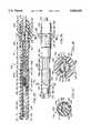
- FIG. 1is a side elevational view of a steerable catheter incorporating the present invention.
- FIG. 2is a side elevational view partially in cross-section showing one embodiment of a steerable catheter incorporating the present,invention utilizing a shape-memory element.
- FIG. 3is a cross-sectional view taken along the line 3--3 of FIG. 2.
- FIGS. 4A, 4B and 4Cshow three examples of how an adjustable bend location in the steerable catheter makes possible bends in different locations in the distal extremity of the catheter.
- FIG. 5is a diagrammatic illustration showing the manner in which the steerable catheter of the present invention can be utilized in a human heart to provide a different bend location to make it possible to reach difficult-to-reach portions of the wall forming a chamber in the heart.
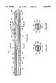
- FIG. 6is a partial cross-sectional view of another embodiment of a steerable catheter incorporating the present invention utilizing removable stiffening elements having weakened portions at different longitudinal positions of the stiffening elements.
- FIG. 7is a cross-sectional view taken along the line 7--7 of FIG. 6.
- FIGS. 8A, 8B and 8Cshow stiffening elements having weakened regions in different longitudinal portions of the stiffening element.
- FIG. 9is a partial cross-sectional view of the distal extremity of another embodiment of a steerable catheter incorporating the present invention utilizing telescoping stiffening elements.
- FIG. 10is a cross-sectional view taken along the line 10--10 of FIG. 9.
- FIG. 11is a side elevational view of another embodiment of a steerable catheter incorporating the present invention.
- FIG. 12is a cross-sectional view taken along line 12--12 of FIG. 11.
- FIG. 13is a cross-sectional view taken along line 13--13 of FIG. 11.
- FIG. 14is a cross-sectional view taken along line 14--14 of FIG. 11.
- FIG. 15is an enlarged cross-sectional view of the handle of the steerable catheter shown in FIG. 11.
- FIG. 16is a cross-sectional view of a portion of the handle shown in FIG. 15 with certain portions being shown in cross-section and rotated by 90° from that shown in FIG. 15.
- FIG. 17is a cross-sectional view taken along line 17--17 of FIG. 16.
- FIG. 18is a cross-sectional view taken along line 18--18 of FIG. 16.
- FIG. 19is an enlarged cross-sectional view of the distal extremity of the catheter shown in FIG. 11.
- FIG. 20is a cross-sectional view similar to FIG. 19 but rotated by 90°.
- FIGS. 21 and 22are cross-sectional views of the distal extremity of the catheter shown in FIG. 1 showing in partially schematic form the manner in which different radius bends can be achieved by different positions of the bend location mandrel.
- FIG. 23is an enlarged partial cross-sectional View of the distal extremity of the catheter encircled on FIG. 21 showing how bending is accomplished.
- FIG. 24is a cross-sectional view similar to FIG. 20 showing another embodiment of the present invention.
- FIG. 25is a cross-sectional view taken along the line 25--25 of FIG. 24.
- FIG. 26is a cross-sectional view taken along the line 26--26 of FIG. 24.
- the steerable catheter of the present inventionconsists of a flexible elongate tubular member having proximal and distal extremities.
- a plurality of circumferentially spaced-apart flexible elementsare disposed in the distal extremity for causing bending of the distal extremity of the flexible elongate member.
- Movable meansis disposed in the distal extremity of the flexible elongate member for selecting the location where bending in the distal extremity will take place and the radius of the bend.
- the steerable catheter 11 incorporating the present inventionconsists of a flexible elongate member 12 formed of a suitable material such as plastic which is provided with proximal and distal extremities 13 and 14.
- An ablation electrode 16is carried by the distal extremity 14.
- a hand-held control mechanism 17is mounted on the proximal extremity 13.
- the hand-held control mechanism 17can be of various types. For example it can be of the type which can be utilized for actuating pull wires (not shown) extending longitudinally of the flexible elongate tubular member 12 which are well known to those skilled in the art and which can be utilized for bending the distal extremity of the flexible elongate tubular member 12.
- a steerable catheter 21which consists of a flexible elongate tubular member 22 which is provided with proximal and distal extremities 23 and 24.
- a metal ablation electrode 26is secured to the distal extremity 24.
- a hand-held control mechanism 27is mounted on the proximal extremity 23 of the flexible elongate tubular member 22.
- the flexible elongate tubular member 22is formed of a suitable material such as plastic and is provided with a plurality of circumferentially spaced-apart lumens 31-36, and a central lumen 37, all of which extend the length of the flexible elongate tubular member 22.
- a plurality of flexible elongate elementsas for example three of such elements 41, 42 and 43, are disposed 120° apart and are provided in the lumens 31, 33 and 35.
- These flexible elongate elements 41, 42 and 43are disposed in the distal extremity 24 of the flexible elongate tubular member 22 and are formed of a material which has a negative coefficient of expansion.
- the distal extremities of these flexible elongate members 41, 42 and 43are connected to a common ground return 44 provided in the lumen 34.
- the three flexible elongate elements 41, 42 and 43are also connected to conductors (not shown) which extend to the proximal extremity 23 of the flexible elongate member and with the ground return 44 connected into a cable 46 extending from the control mechanism 17 and are connected to a joystick control console 47 of the type described in co-pending application Ser. No. 07/793,858, filed Nov. 18, 1991, and which includes a joystick 48.
- the ablation electrode 26is connected by a conductor 51 provided in the lumen 32 and extending into the control mechanism 17 and is connected to a suitable ablation power supply (not shown) conventionally used with such catheters.
- Bend adjustment means 56is provided in the distal extremity 24 of the flexible elongate tubular member 22 and consists of a shape-memory element 57 formed of a suitable material such as Nitinol which has been provided with a memory which makes it assume a straight condition when it is heated such as by the application of electrical energy thereto.
- the shape-memory element 57is provided with proximal and distal extremities 58 and 59.
- the proximal extremity 58is connected by a joint 61 to a conductor 62 which extends into the control mechanism and is connected as hereinafter described.
- the distal extremity 59is connected to a ground return conductor 44 by wire 63.
- the shape-memory element 57can have a suitable diameter, as for example 5-20 mils.
- the bend adjustment means 56also includes selective conductive bypass means 66 which is movable longitudinally along the length of the shape-memory element 57 to selectively inhibit current flow in a portion of the shape-memory element to permit bending of the shape-memory element 57 in that portion of the shape-memory element.
- the conductive bypass means 66 as shown in FIGS. 2 and 3consists of an elongate cylindrical sleeve 67 formed of a suitable conducting material, as for example a silver mesh or braid, through which the shape-memory element 57 extends.
- Meansis provided for adjusting the sleeve 67 longitudinally over the shape-memory element 57 and consists of a flexible tubular member 68 formed of a suitable insulating material such as plastic which is slidably mounted in the central lumen 37.
- the tubular member 68is provided with a bore 69 therein extending the length thereof and in which the shape-memory element 57 is disposed. As can be seen particularly in FIG.
- the sleeve 67has one end secured to the distal extremity of the flexible tubular member 68.
- the other end of the sleeve 67is supported by another tubular member 71 of the same material and of the same diameter as the flexible tubular member 68 and is provided with a bore 72 through which the shape-memory element 57 extends.
- the sleeve 67can be affixed to the tubular members 68 and 71 by suitable means such as an adhesive.
- the shape-memory elementIn order to ensure good conductivity between the silver braid or mesh sleeve 67, the shape-memory element should be cleaned with nitric and hydrochloric acids to remove any oxidation which may be present on the shape-memory element 57. This ensures that there is good electrical contact between the sleeve 67 and the shape-memory element so that minimal or no current flows in the portion of the shape-memory element 57 which is covered by the sleeve.
- Meansis provided for controlling the movement of the flexible tubular member 68 and the sleeve 67 carried thereby from the control mechanism 27 and consists of a control member 76 which is secured to the proximal extremity of the tubular member 68.
- the control member 73extends diametrically of the tubular member 68 through a longitudinally extending slot 77 provided in the sidewall of a cylindrical housing 78.
- the cylindrical housing 78can be formed of a suitable material such as plastic or metal, and is sized in such a manner so that it is adapted to be held by the human hand. For example, it can have a diameter of approximately 1" and a length of 5-6".
- the conductor 62is connected to a cable 82 which extends out of the housing 78 and is connected to a variable current power supply 83 which is provided with a control knob 84 to adjust the amount of current which is supplied to the sleeve 67.
- the variable current power supply 83is also provided with another cable 86 which is connected to the ground return conductor 44.
- the sleeve 67which is in close intimate contact with the shape-memory element 57, serves as a current bypass or bridge and causes the current to flow through the highly conductive silver mesh sleeve 67 to thereby bridge that portion of the shape-memory element 57 covered thereby so that it remains relatively flexible.
- the portion of the shape-memory element 57 underlying or within the sleeve 67does not heat up and remains flexible and does not attempt to assume the straight condition of the remainder of the shape-memory element 57.
- FIG. 5shows by providing different bend locations for the steerable catheter 11, it is possible to reach difficult-to-reach positions in the human heart.
- bends 94 and 96 in the catheter 11Two different bends represented by the bends 94 and 96 in the catheter 11 are shown in which the bend 96 in contradistinction to the bend 94 makes it possible to reach a difficult-to-reach area of the wall 96 forming the chamber 97 of the human heart 98.
- FIGS. 6 and 7Another embodiment of a steerable catheter incorporating the present invention is shown in the catheter 101 in FIGS. 6 and 7 which consists of a flexible elongate tubular member 102 formed of a suitable material such as plastic which is provided with a distal extremity 103 having a metal electrode 104 provided thereon.
- the flexible elongate member 102is provided with a plurality of circumferentially spaced-apart lumens 106-111 and a central lumen 112.
- At least three pull wires 116, 117 and 118are provided in the lumens 106, 108 and 109, which are connected into the distal extremity and which extend to the proximal end of the catheter 101 and are controlled by a conventional control mechanism (not shown) for causing bending of the distal extremity of the tubular elongate member 102.
- a conductor 119is provided in the lumen 110 and is connected to the electrode 104.
- An elongate stiffening element 121is slidably mounted in the central lumen 112. This stiffening element 121 is provided with a weakened longitudinal portion 121a of the stiffening element 121.
- This weakened portion 121acan be of a suitable length, as for example 1-5 cm. It can be seen that by utilizing such a stiffening element with such a weakened portion that the bending of the distal extremity 103 of the flexible elongate tubular member 102 will occur in the region of the weakened portion 121a.
- the stiffener element 121can be interchanged with other stiffener elements, as for example stiffener elements 126, 127 and 128, as shown in FIGS. 8A, 8B and 8C, having weakened longitudinal portions 126a, 127a and 128a, respectively, at different longitudinal positions of the stiffener elements 126, 127 and 128. It can be seen that by selecting an appropriate stiffener element that the bend in the distal extremity of the flexible elongate member 102 can be made to occur in the desired location to provide different hinge points and also to provide different lengths of the stiffener element extending beyond the weakened region or hinge point.
- the catheter 131consists of a flexible elongate member 132 formed of a suitable material such as plastic which is provided with a distal extremity 133 to which there is secured a tip electrode 134.
- the flexible elongate member 132is provided with a plurality of circumferentially spaced-apart lumens 137,138,139,141 and 142 and a central lumen 143.
- At least three flexible elongate elements 146, 147 and 148are disposed in the lumens 136, 138 and 139 and are formed of a material having a negative coefficient of expansion.
- the means for adjusting the bend location for the bending of the distal extremity 133 of the flexible elongate tubular member 132is in the form of a telescoping assembly 151 formed of a suitable material such as stainless steel mounted in the central lumen of the distal extremity 133 of the catheter 131.
- the telescoping assembly 151is movable between collapsed and extended positions and consists of an outer cylindrical member 152 which is secured within the distal extremity 133 by suitable means such as an adhesive.
- the outer cylindrical memberis provided with a cylindrical bore 153 and a swaged end 154 providing an opening 155 in communication with the bore 153.
- An intermediate cylindrical member 156is slidably mounted within the outer cylindrical member 152 and is provided with a flanged end 157 which is adapted to engage the swaged end 154 of the outer cylindrical member 152.
- the intermediate cylindrical member 156is provided with a bore 158 and has a swaged end 159 forming a hole 161 extending therethrough.
- An inner cylindrical member 164is provided which has a flange 166 which is adapted to travel in the bore 158. The inner cylindrical member 164 travels through the hole 161 and forms the distal extremity of an elongate flexible push-pull element 171 which extends to the proximal extremity (not shown) of the flexible elongate member 132.
- the flexible elongate element 171can be formed of a suitable material such as stainless steel and can have a diameter of 0.012-0.025". It is provided a portion 171a of reduced diameter in close proximity to the inner cylindrical member 164 as shown in FIG. 9. By way of example, it can have a reduced diameter ranging from 0.006" to 0.015". The diameter of the flexible elongate element 171 should be of a diameter which is slightly greater than the size of the hole 161 for a purpose hereinafter described.
- the hinge point or bend location for the distal extremity 133 of the flexible elongate element 132can be readily adjusted.
- the telescoping assembly 151is in a collapsed position in which the push-pull element 171 has been pushed towards the distal extremity so that an enlarged portion 1 of the flexible elongate member 171 is in engagement with the proximal extremity of the intermediate cylindrical member 156 and the intermediate cylindrical member 164 is disposed entirely within the outer cylindrical member 132.
- FIGS. 11-20Another embodiment of the steerable catheter of the present invention having an adjustable bend location and/or radius is shown in FIGS. 11-20.
- the steerable catheter 201consists of a flexible elongate member 202 having proximal and distal extremities 203 and 204.
- the proximal extremity 203is secured to the handle 206 in the form of a control mechanism which is adapted to be grasped by the human hand.
- the flexible elongate member 202is comprised of a first or inner shaft 211 and a second or outer shaft or sleeve 212 coaxially mounted on the first or inner shaft 211.
- the inner shaft 211is in the form of a plastic extrusion which has been provided with a plurality of lumens extending therethrough.
- the inner shaft 211is formed in two portions 211a and 211b. Both portions can be formed of the same plastic material, as for example PEBAX manufactured by Atochem, Inc. of Glen Rock, N.J.
- portion 211a of a softer materialsuch as PEBAX having a 35 Shore D hardness
- portion 211b of a harder materialas for example PEBAX having a 72 Shore D hardness.
- the portion 211bhas a smaller outer diameter than the portion 211a to accommodate the second or outer shaft or sleeve 212 and to provide a smooth outer surface for the flexible elongate member 202.
- the two portions 211a and 211bcan be readily joined together by a heat fusing process since both portions are formed of a PEBAX material.
- the two portions 211a and 211b of the first or inner shaft 211are provided with a centrally disposed lumen 213 extending the length thereof and two additional lumens 214 and 216 aligned diametrically with lumen 213 and extending the length of the shaft 211.
- Two additional crescent or moon-shaped lumens 217 and 218are provided in the shaft 211 on opposite sides of the diametrically aligned lumens 213, 214, and 216.
- the second or outer shaft or sleeve 212is formed of a braided PEBAX material which has a braid embedded therein formed of a suitable material such as sixteen 40-gauge stainless steel strands having a braid angle of 60°.
- the second or outer shaft or sleeve 212can have a suitable wall thickness, as for example 0.020" with a corresponding reduction in the diameter of the portion 211b with respect to the portion 211a so that the outer surface of the sleeve is flush with the outer surface of the portion 211a.
- the braided sleeve or shaft 212stops short of the distal extremity of the flexible elongate member 202 as indicated by the line 219 (see FIG. 19).
- the second or outer shaft or sleeve 212serves to provide good torque transfer characteristics for the flexible elongate member 202.
- the portion 211a of the first inner shaft 211has its distal extremity rotated or twisted through an angle, as for example from 270° to 250° and preferably approximately 360° through a length ranging from 10"-20" and preferably a distance of about approximately 15".
- FIG. 12shows the initial starting position for the twist of the inner shaft portion 211a.
- FIG. 13shows that the twist of the shaft portion 211a after it has been twisted by 180° and FIG.
- FIG. 14shows the final twist of the shaft portion 211a after it has been twisted through 360° .
- This rotation of the distal extremity of the shaft portion 211ais retained in the flexible elongate member 202 by affixing the sleeve 212 at a suitable distance as for example 18" from the distal extremity of the flexible elongate member 202 as represented by the cross-section of FIG. 12 by suitable means such as heat staking and similarly approximately 3" from the distal extremity as represented by the cross-section in FIG.
- a tip electrode 221is mounted on the distal extremity of the portion 211a and is formed of a suitable material such as platinum and is formed as a deep drawn cup with a rounded distal extremity and having an outer circumference which corresponds to the outer circumference of the portion 211a.
- the tip electrode 221can have a suitable diameter, as for example 0.091" and a have a suitable length, as for example 4 millimeters.
- the tip electrode 221is provided with a longitudinal extending cavity 222. The distal extremity of the portion 211a is necked down and inserted into the cavity 222 and is retained therein by suitable means such as an adhesive (not shown).
- the tip electrode 221is also secured to the distal extremity of the portion 211a by a member 223 in the form of a stainless steel hypotube having an outside diameter of approximately 0.025" and an inside diameter of 0.019" and having a length of approximately 1/4" which is retained within the cavity 222 by a suitable means such as solder 224.
- the members 223are secured to one end of a ribbon 226 by suitable means such as welding the ribbon 226 is formed of a suitable material such as a superelastic Nitinol which has a programmed memory of a straight shape. It can have suitable dimensions, as for example a width of 0.018" and a thickness of 0.006" and a length of approximately 3".
- the ribbon 226is slidably disposed in the central lumen 213.
- Meansis provided for forming an electrical connection to the tip electrode 221 and consists of a insulated conductor 227 which has one end electrically connected to the tip 221 by the solder 224.
- the conductor 227extends through the lumen 216 through the proximal extremity of the flexible elongate member 202.
- a plurality of conductive rings 228 formed Of a suitable material such as platinumare mounted in insulated spaced-apart positions on the portion 211a the shaft 211 and are connected to insulated conductors 229 which also extend to the proximal extremity of the flexible elongate member 202 through the lumen 216.
- Meansis provided for causing bending of the distal extremity of the flexible elongate member 202 and consists of a pull wire 231 formed of a suitable material such as stainless steel having a diameter of 0.005".
- the pull wire 231is slidably mounted in the lumen 214 and is connected into the tip electrode 221 by having a beaded end 232 secured within the solder 224.
- the pull wireis coated with Teflon (not shown).
- a bend location mandrel 236is slidably mounted in the central lumen 213. As shown, it can be circular in cross-section and can have a suitable diameter, as for example 0.017". It is formed of a suitable material such as Nitinol. The proximal extremity of the bend location mandrel 236 is secured within the handle 206 as hereinafter described. The distal extremity of the mandrel 236 is secured by welding to an elongate ribbon 237 which is rectangular in cross-section and which is disposed in the central lumen 213. The ribbon 237 also is formed of a superelastic Nitinol which is rectangular in cross-section and can have suitable dimensions such as 0.019" and a thickness of 0.008".
- the ribbon 237has a memory which causes it to return to a straight position when it is free to move.
- the ribbon 237is mounted on the mandrel 236 so that it flexes in a direction which is at right angles to the width of the ribbon to permit bending of the portion 211a of the shaft 211 in the direction in which it can be pulled by the pull wire 231 but inhibiting flexing in a direction which is at right angles to the plane formed by the width of the ribbon.
- the ribbon 237overlaps the ribbon 226 and is slidable longitudinally with respect to the ribbon 226 to adjust the bend location as hereinafter described.
- the handle 206is in the form of an assembly which includes an elongate cylindrical body 241 formed of a suitable material such as plastic which is formed of a distal extremity 241a of a larger diameter and a portion 241b of a reduced diameter to form a shoulder 242.
- the body 241is provided with an axially extending bore 243 extending therethrough which opens into a larger bore 244 provided in the distal extremity of the body 241.
- the portion 241b of reduced diameteris provided with an elongate slot 246 extending longitudinally thereof parallel to the longitudinal axis of the body 241.
- the portion 241a of larger diameteris also provided with first and second diametrically opposed open-ended slots 247 which are open at their distal extremities because they extend through the distal extremity of the body portion 241a.
- the slots 247extend longitudinally of the body 241 and are parallel to the axis of the body 241. As shown in FIG. 16, the slots 247 are positioned so that at least one is aligned with the slot 246 in the portion 241b.
- the portion 241b of reduced diameteris also provided with spaced-apart inner recesses 249 on the outer cylindrical surface thereof.
- the body portion 241ais also provided with an annular recess 251 opening through the outer surface thereof.
- the handle 206also includes a cylindrical nose piece 256 that has substantially the same outer diameter as the portion 241a of the body 241. It is provided with a rounded distal extremity 257.
- the nose piece 256is provided with a large bore 258 in the proximal extremity of the same which opens into a smaller bore 259 which in turn opens into a slightly larger bore 261.
- the nose pieceis provided with an annular recess 262 on the proximal extremity of its outer surface which is sized so that the proximal extremity of the nose piece 256 can be fit within the bore 244 provided in the body 241.
- the nose piece 256is also provided with an annular recess 263 which is spaced distally from the recess 262.
- the handle 206includes a handle member in the form of a circular knob 266 which is slidably mounted on the body 241 and the nose piece 256 when the nose piece is assembled into the body 241.
- the handle member 266is in the form of an elongate sleeve 267 which has a bore 268 extending there through which is sized so that a slip fit is formed between the sleeve 267 and the body portion 241a and the nose piece 256.
- the handle member 266is provided with an outwardly and circumferentially extending waist 269 which is provided with a rounded contour to facilitate grasping of the same by fingers of the hand holding the handle as for example the thumb and forefinger.
- Meansis provided for securing the handle member 266 to the body portion 241a that consists of a cylindrical pin 271 formed of a suitable material such as stainless steel which extends through the waist 269 and extends through the slots 247 and 264 (see FIG. 18) which serves to limit the sliding movement of the handle member 266 to the length of the cooperating slots 247 and 264.
- the nose piece 256is provided with first and second diametrically opposed slots 264 which open through the proximal extremity of the nose piece 256 and are aligned with the slots 247 in the body 241 so that when the nose piece 257 is assembled into the body 241, the slots 264 close the open ended slots 247.
- a pin 271is disposed in counter-sunk bores 272 in the handle member which after the pin 271 is in place are filled with additional plastic 273 that is ground and polished so that the pin 271 is hidden from view of the human eye.
- the proximal extremity 203 of the flexible elongate member 202is disposed in the bore 259 in the nose piece 256 is retained therein by suitable means such as an adhesive (not shown).
- a strain relief sleeve 276 formed of a suitable material such as plasticis mounted in the bore 261 and is retained therein by suitable means such as an adhesive (not shown) and extends over the proximal extremity of the flexible elongate member 202 (see FIG. 11).
- the bend location mandrel 236extends from the proximal extremity of the flexible elongate member 202 and passes through a hole 281 provided in the pin (see FIG. 18).
- the pull wire 231also extends from the proximal extremity of the flexible elongate member 202 into the handle 206 and extends through a hole 282 offset from the hole 281 (see FIG. 18).
- the handle 206also consists of the sleeve 286 which is provided with a portion 286a of a larger diameter handle and a portion 286b of a smaller diameter to form a shoulder 287.
- the portion 286a of larger diameteris provided with a plurality of circumferentially spaced apart longitudinally extending recesses 288 which are adapted to be grasped by the fingers of the hand holding the handle 206.
- the portion 286bis provided with a helically extending slot 291 which has its ends coterminus with the ends of the slot 246 in the portion 286b when the sleeve 286 is positioned over the portion 241b as shown in FIGS. 15 and 16.
- O-rings 292provided in the annular recesses 248 and 249 and serve to provide a slight frictional engagement between the sleeve 286 and the body 241 to slightly inhibit the rotation of the sleeve 286 with respect to the body 241.
- the o-ringalso prevents a fluid from entering the handle 206.
- An O-ring 273is provided in the recess 263 which serves to provide a slight frictional engagement to retain the handle member 266 in a desired position longitudinally of the body 241 while still permitting relatively free movement of the handle member 266 relative to the body 241.
- the bend location mandrel 236extends through the bore 243 of the body 241.
- the bend location mandrel 236is formed of a suitable material such as 0.018" Nitinol wire. It extends through a bore 294 provided in a block 296 formed of a suitable material such as plastic.
- the bore 294opens into a larger bore 297 in the block 296 which opens through the distal extremity of the block.
- a sleeve 301 formed of a suitable material such as stainless steel hypotube having an inside diameter of 0.020" and outside diameter of 0.032"is secured to the proximal extremity of the bend location mandrel 236 by suitable means such as a TIG weld.
- the sleeve 301is disposed in the bore 297 and retains the proximal extremity of the bend location mandrel 236 within the block 296 which as shown in FIG. 17 can have a rectangular cross-section.
- the sleeve 301 with the bend location mandrel 236is retained within the block 296 by a dowel pin 302 which extends through a bore 303 transversely of the block 296 immediately behind the sleeve 301 to retain the sleeve 301 in the bore 297.
- the pin 302also extends through the elongate slot 246 provided in the body 241 and into the helical slot 291 whereby as the sleeve 286 is rotated, the pin 302 will be caused to translate longitudinally of the handle 206 in the slot 246 to advance and retract the bend location mandrel 236 for a purpose hereinafter described.
- the handle 206includes a cylindrical end piece 306 also formed of a suitable material such as plastic which is provided with a bore 307 opening through the distal extremity of the same.
- the bore 307opens into a smaller bore 308 which in turn opens into a still smaller bore 309.
- the bore 309opens into a larger bore 311 (see FIG. 15).
- a plug 312is seated within the bore 311 and is retained therein by suitable means such as an adhesive and carries a female electrical connector 313 of a conventional type which is recessed therein and which is provided with female recesses 314 formed of a conducting material which are connected to the conductors 226.
- a male connector 316 of a conventional typeis adapted to seat within the female connector 313 (see FIG. 11) and is connected to a cable 317 that carries conductors 318 connected to conventional pins 319 that are adapted to be connected into conventional instrumentation for performing an ablation procedure as hereinafter described.
- the distal extremity 204 of the flexible elongate member 202 of the steerable catheter 201can be introduced into the vessel of the patient, as for example a femoral artery in a conventional manner and introduced into the heart of the patient to a desired chamber of the heart by steering the distal extremity 204 of the flexible elongate member 202.
- the advancement of the distal extremity 204can be observed fluoroscopically.
- large radius and small radius bendsmay be provided in the distal extremity 204 to make it possible to negotiate the vessel leading to the heart and to enter appropriate pathways in the heart to position the distal extremity 204 in an appropriate position in the chamber of the heart to perform an ablation.
- the cylindrical knob provided by the sleeve 286is in a position so that the dowel pin 302 is in the proximal extremity of the helical slot 291 as shown in FIG. 1 so that the bend location mandrel 236 has been retracted to its extreme proximal position.
- the portion 211a of the shaft 211will be relatively soft and floppy so that it can readily negotiate the femoral artery or other vessel into which it is being introduced.
- a bendcan be placed in the distal extremity 204 when desired to negotiate a tortuosity in the vessel.
- the bend location mandrel 236can be advanced by rotation of the sleeve 286 to cause the distal extremity of the mandrel 236 and the ribbon 237 carried thereby to be advanced distally to progressively overlap the ribbon 226 to cause the radius of the bend to be decreased. Extending the mandrel 236 with the ribbon 237 carried thereby to its distal-most extremity it can create a bend having a radius as small as 18 millimeters as shown in FIG. 22. Thus it can be seen that the radius of the bend can be increased in connection of the present embodiment without substantially changing the position of the bend. In the previous embodiments hereinbefore described, the bend location was changed but the radius was kept relatively constant.
- the catheter 201has its distal extremity 204 arranged in such a manner that it only bends in a single direction because of the orientation of the ribbons 237 and 238 so that bending can only occur in a direction which is perpendicular to the width of the ribbons 226 and 237.
- the direction of bendingwill only occur in one direction because the pull wire 231 is disposed on one side of the ribbons 236 and 237 so that the ribbons will be bent in a direction toward the pull wires 231.
- the distal extremitycan be torqued through an angle 360 degrees and more by utilizing the hand holding the handle to rotate the handle 206 the desired amount.
- the multilumen shaft 211has been twisted through 360° as hereinbefore described within the braided or outer shaft or sleeve 212 so that the pull wire 231 shows no preferential orientation as it goes over the aortic arch. Because of the helix placed in the pull wire 231 by twisting of the portion 211a, the pull wire cannot assume a preferred orientation as it travels over the aortic arch. The approximately 15 centimeters of the flexible elongate member which is provided with this twist extends along the length of the portion of the catheter which typically would form the bend going over the aortic arch.
- the distal extremity 204 of the flexible elongate member 202can be readily advanced into a chamber of the heart with bends in the heart being readily negotiated by placing the appropriate bend in the distal extremity and by selecting the appropriate radius for the bend. This can be readily accomplished by one hand of the physician holding the handle for rotation of the same and for creating bends of various radii by operation of the circular hob 266 and the sleeve hob 286.
- the distal extremity 204can be readily advanced so that the tip electrode 221 and, if desired, the other spring electrodes 228 can be brought into engagement with the wall of the heart by appropriate operation of the handle 206.
- the bend in the distal extremity of the cathetercan be removed by appropriate movement of the circular knob 266 and the sleeve knob 286 to permit removal of the steerable catheter 201 from the heart and then from the vessel of the patient.
- the steerable catheter 201has several significant features. Because of the twisting of the catheter shaft 211, it is possible to avoid whipping of the catheter shaft and to prevent the pull wire from moving into a preferential position.
- the braided shaft or sleeve 212serves two functions. It serves to prevent unwinding of the twist placed in the inner shaft 211. Also it makes it possible to transfer torque from one end of the outer shaft 212 to the other end of the shaft 212.
- a pair of Nitinol wires of a suitable diameter such as 0.010"can be welded together along their length to provide a flat member which corresponds essentially to the ribbon 226.
- the mandrel 236can have such a length so it overlaps the wires.
- a Nitinol ribboncan be soldered into the tip with the proximal extremity of the ribbon being connected to the pull wire 231.
- the stripwould have a memory which would preferentially cause it to seek a straight shape.
- a Nitinol ribboncould be secured to the proximal extremity of the member 223 shown in FIG. 19 which also would have a memory which would cause it to assume a straight condition when permitted to do so.
- the mandrel 236could extend distally so that it overlaps such a ribbon.
- a superelastic memberhas been provided with a memory of a straight shape so that when the pull wire is released, the distal extremity 202 of the flexible elongate member will assume a relatively straight shape so that it can be introduced into and removed from vessels in the patient.
- FIGS. 24, 25, and 26Another embodiment of the invention is shown in FIGS. 24, 25, and 26 which is very similar to the embodiment shown in FIGS. 19 and 20 with, however, certain improvements made thereto to provide additional assurance that the distal extremity of the catheter 201 after a bend has additional transverse or lateral stiffness to help ensure that the tip electrode 221 as well as the conductive rings 228 remain in contact with the moving wall of the beating heart while still making it possible to more readily form bends in the distal extremity of the catheter.
- the construction making this possibleis shown particularly in FIGS.
- the flexible elongate member 202can have a suitable length, as for example 85 centimeters whereas with the distal from which the portion 212a begins having a length of approximately 15 centimeters.
- the portion 212ais formed of a lower durometer material than the portion 212.
- the braided second or outer shaft 212can be formed of shaft material such as PEBAX 7233 having a 72 D durometer and being impregnated with approximately 20% by weight of barium sulfate (BaSO 4 ).
- a softer materialcan be utilized which in accordance with the present invention should be at least 25% softer and as much as approximately 50% softer.
- this shaft materialcan be formed of PEBAX 3533 and also is filled with 20% by weight of barium sulfate.
- the materials utilized for the shaft 212 and the distal extremity 212acan be formed of various durometer materials ranging from 35 D to 72 D Shore hardness. However, as pointed out above, in accordance with the present invention it is desirable that the hardness of the outer shaft portion 212a be at least 25% less than the hardness of the material utilized for the outer shaft 212.
- the braid utilized in the portion 212acan be very similar to that utilized in the portion 212. For,example, the braid can be formed of a 304 stainless steel wire having a diameter of 0.003". Also byway of example it can be formed of 16 fillaments with a one over two configuration and a 60° braid angle.
- the first or inner shaft 211can be formed of a suitable shaft material such as PEBAX 5533 with a Shore hardness of 55 D and formed entirely of plastic with a 20% barium sulfate filler.
- the construction shown in FIGS. 24, 25 and 26has a number of advantages.
- the braid in the portion 212awith the shaft material being formed of a lesser Shore hardness material it is possible to provide a distal extremity in which a bend can be formed more easily while still providing improved lateral stiffness.
- the distal extremityis formed into a bend so that the electrodes carried by the distal extremity can have additional springiness and be maintained in engagement with the wall of the heart while the heart is beating.
- the distal extremityis less floppy than the distal extremity in the embodiments hereinbefore described.
- the adding of the additional braided portion 212ahas made it possible to increase the lateral stiffness of the tip of the catheter by making it possible for the physician or other person utilizing the catheter to torque the catheter into a position so that the tip 21 and the ring electrodes 228 can be brought firmly into engagement with the wall of the heart and be retained in engagement with the wall of a beating heart.
- the distal extremity of the catheterwill hug the wall of the heart regardless of how the wall is moving during beating of the heart. This helps to ensure that a good lesion will be formed when RF energy is supplied to the tip electrode 221 and to the ring electrodes 228.
Landscapes
- Health & Medical Sciences (AREA)
- Life Sciences & Earth Sciences (AREA)
- Engineering & Computer Science (AREA)
- Animal Behavior & Ethology (AREA)
- Veterinary Medicine (AREA)
- Public Health (AREA)
- Biomedical Technology (AREA)
- Heart & Thoracic Surgery (AREA)
- General Health & Medical Sciences (AREA)
- Anesthesiology (AREA)
- Pulmonology (AREA)
- Biophysics (AREA)
- Hematology (AREA)
- Surgery (AREA)
- Mechanical Engineering (AREA)
- Physics & Mathematics (AREA)
- Plasma & Fusion (AREA)
- Nuclear Medicine, Radiotherapy & Molecular Imaging (AREA)
- Otolaryngology (AREA)
- Cardiology (AREA)
- Medical Informatics (AREA)
- Molecular Biology (AREA)
- Media Introduction/Drainage Providing Device (AREA)
Abstract
Description
Claims (23)
Priority Applications (1)
| Application Number | Priority Date | Filing Date | Title |
|---|---|---|---|
| US08/383,462US5656029A (en) | 1992-12-01 | 1995-02-08 | Steerable catheter with adjustable bend location and/or radius and method |
Applications Claiming Priority (5)
| Application Number | Priority Date | Filing Date | Title |
|---|---|---|---|
| US98396292A | 1992-12-01 | 1992-12-01 | |
| US08/134,487US5389073A (en) | 1992-12-01 | 1993-10-12 | Steerable catheter with adjustable bend location |
| US08/147,753US5391147A (en) | 1992-12-01 | 1993-11-05 | Steerable catheter with adjustable bend location and/or radius and method |
| US08/212,001US5478330A (en) | 1992-12-01 | 1994-03-11 | Steerable catheter with adjustable bend location and/or radius and method |
| US08/383,462US5656029A (en) | 1992-12-01 | 1995-02-08 | Steerable catheter with adjustable bend location and/or radius and method |
Related Parent Applications (1)
| Application Number | Title | Priority Date | Filing Date |
|---|---|---|---|
| US08/212,001DivisionUS5478330A (en) | 1992-12-01 | 1994-03-11 | Steerable catheter with adjustable bend location and/or radius and method |
Publications (1)
| Publication Number | Publication Date |
|---|---|
| US5656029Atrue US5656029A (en) | 1997-08-12 |
Family
ID=27384592
Family Applications (3)
| Application Number | Title | Priority Date | Filing Date |
|---|---|---|---|
| US08/212,001Expired - LifetimeUS5478330A (en) | 1992-12-01 | 1994-03-11 | Steerable catheter with adjustable bend location and/or radius and method |
| US08/382,622Expired - LifetimeUS5588964A (en) | 1992-12-01 | 1995-02-02 | Steerable catheter with adjustable bend location and/or radius and method |
| US08/383,462Expired - LifetimeUS5656029A (en) | 1992-12-01 | 1995-02-08 | Steerable catheter with adjustable bend location and/or radius and method |
Family Applications Before (2)
| Application Number | Title | Priority Date | Filing Date |
|---|---|---|---|
| US08/212,001Expired - LifetimeUS5478330A (en) | 1992-12-01 | 1994-03-11 | Steerable catheter with adjustable bend location and/or radius and method |
| US08/382,622Expired - LifetimeUS5588964A (en) | 1992-12-01 | 1995-02-02 | Steerable catheter with adjustable bend location and/or radius and method |
Country Status (2)
| Country | Link |
|---|---|
| US (3) | US5478330A (en) |
| CA (1) | CA2109980A1 (en) |
Cited By (200)
| Publication number | Priority date | Publication date | Assignee | Title |
|---|---|---|---|---|
| WO1998043530A1 (en)* | 1997-03-31 | 1998-10-08 | Biosense Inc. | Deflectable catheter |
| US5873851A (en)* | 1996-08-28 | 1999-02-23 | Microsurgical Technology, Inc. | Ophthalmic irrigator-aspirator having a flexible outer cannula |
| US5897529A (en)* | 1997-09-05 | 1999-04-27 | Cordis Webster, Inc. | Steerable deflectable catheter having improved flexibility |
| WO1999030764A1 (en)* | 1997-12-18 | 1999-06-24 | C.R. Bard, Inc. | Systems and methods for local delivery of an agent |
| US6033376A (en)* | 1998-09-30 | 2000-03-07 | Allergan Sales, Inc. | Wound shaper sleeve |
| WO2000016848A1 (en) | 1998-09-24 | 2000-03-30 | C.R. Bard, Inc. | Systems and methods for treating ischemia |
| US6066125A (en)* | 1997-09-05 | 2000-05-23 | Cordis Webster, Inc. | Omni-directional steerable catheter |
| US6083216A (en)* | 1999-01-05 | 2000-07-04 | Intermedics Inc. | Bent cardiac lead with shape memory torque coil |
| US6161543A (en)* | 1993-02-22 | 2000-12-19 | Epicor, Inc. | Methods of epicardial ablation for creating a lesion around the pulmonary veins |
| US6171277B1 (en) | 1997-12-01 | 2001-01-09 | Cordis Webster, Inc. | Bi-directional control handle for steerable catheter |
| US6179809B1 (en)* | 1997-09-24 | 2001-01-30 | Eclipse Surgical Technologies, Inc. | Drug delivery catheter with tip alignment |
| US6183463B1 (en) | 1997-12-01 | 2001-02-06 | Cordis Webster, Inc. | Bidirectional steerable cathether with bidirectional control handle |
| US6197324B1 (en) | 1997-12-18 | 2001-03-06 | C. R. Bard, Inc. | System and methods for local delivery of an agent |
| US6198974B1 (en) | 1998-08-14 | 2001-03-06 | Cordis Webster, Inc. | Bi-directional steerable catheter |
| US6210407B1 (en) | 1998-12-03 | 2001-04-03 | Cordis Webster, Inc. | Bi-directional electrode catheter |
| US6237605B1 (en) | 1996-10-22 | 2001-05-29 | Epicor, Inc. | Methods of epicardial ablation |
| US6251079B1 (en) | 1998-09-30 | 2001-06-26 | C. R. Bard, Inc. | Transthoracic drug delivery device |
| US6287301B1 (en) | 1997-07-29 | 2001-09-11 | Scimed Life Systems, Inc. | Catheter having improved torque transmission capability and method of making the same |
| US6296620B1 (en) | 1999-12-09 | 2001-10-02 | Advanced Cardiovascular Systems, Inc. | Polymer blends for ultrasonic catheters |
| US6311692B1 (en) | 1996-10-22 | 2001-11-06 | Epicor, Inc. | Apparatus and method for diagnosis and therapy of electrophysiological disease |
| US20020082585A1 (en)* | 1999-06-15 | 2002-06-27 | Sean Carroll | Defined deflection structure |
| WO2002038052A3 (en)* | 2000-11-10 | 2002-10-31 | Boston Scient Ltd | Steerable loop structure |
| US20030073992A1 (en)* | 1996-10-22 | 2003-04-17 | Epicor, Inc. | Methods and devices for ablation |
| US6554794B1 (en)* | 1997-09-24 | 2003-04-29 | Richard L. Mueller | Non-deforming deflectable multi-lumen catheter |
| US6571131B1 (en) | 2000-11-10 | 2003-05-27 | Biosense Webster, Inc. | Deflectable catheter with modifiable handle |
| US20030109778A1 (en)* | 1997-06-20 | 2003-06-12 | Cardiac Assist Devices, Inc. | Electrophysiology/ablation catheter and remote actuator therefor |
| US6579278B1 (en)* | 2000-05-05 | 2003-06-17 | Scimed Life Systems, Inc. | Bi-directional steerable catheter with asymmetric fulcrum |
| US6585717B1 (en) | 1999-06-15 | 2003-07-01 | Cryocath Technologies Inc. | Deflection structure |
| US6596005B1 (en)* | 1998-03-05 | 2003-07-22 | Scimed Life Systems, Inc. | Steerable ablation burr |
| WO2003053504A3 (en)* | 2001-12-07 | 2003-08-14 | Abbott Lab | Catheter deployment device |
| US6645202B1 (en) | 1996-10-22 | 2003-11-11 | Epicor Medical, Inc. | Apparatus and method for ablating tissue |
| US6689128B2 (en) | 1996-10-22 | 2004-02-10 | Epicor Medical, Inc. | Methods and devices for ablation |
| US20040034348A1 (en)* | 2000-11-29 | 2004-02-19 | St. Jude Medical, Daig Division, Inc. | Electrophysiology/ablation catheter having lariat configuration of variable radius |
| US6728563B2 (en) | 2000-11-29 | 2004-04-27 | St. Jude Medical, Daig Division, Inc. | Electrophysiology/ablation catheter having “halo” configuration |
| US20040082947A1 (en)* | 2002-10-25 | 2004-04-29 | The Regents Of The University Of Michigan | Ablation catheters |
| US20040087941A1 (en)* | 1998-05-20 | 2004-05-06 | Wang Paul J. | Cardiac system and method for treatment of cardiac arrhythmias and transmyocardial revascularization |
| US20040143253A1 (en)* | 2003-01-17 | 2004-07-22 | Vanney Guy P. | Ablation catheter assembly having a virtual electrode comprising portholes |
| US20040143254A1 (en)* | 2003-01-21 | 2004-07-22 | Vanney Guy P. | Catheter design that facilitates positioning at tissue to be diagnosed or treated |
| US6805128B1 (en) | 1996-10-22 | 2004-10-19 | Epicor Medical, Inc. | Apparatus and method for ablating tissue |
| WO2004064890A3 (en)* | 2003-01-17 | 2004-12-29 | Scimed Life Systems Inc | Unbalanced reinforcement members for medical device |
| US20050004565A1 (en)* | 2003-07-02 | 2005-01-06 | Guy Vanney | Ablation fluid manifold for ablation catheter |
| US6855160B1 (en) | 1999-08-04 | 2005-02-15 | C. R. Bard, Inc. | Implant and agent delivery device |
| US20050228367A1 (en)* | 1999-01-25 | 2005-10-13 | Marwan Abboud | Leak detection system for catheter based medical device |
| WO2005113057A1 (en)* | 2004-05-17 | 2005-12-01 | C. R. Bard, Inc. | Articulated catheter |
| US20050273096A1 (en)* | 2004-05-27 | 2005-12-08 | Roop John A | Anchoring introducer sheath with distal slots for catheter delivery and translation |
| EP1460954A4 (en)* | 2001-11-29 | 2005-12-14 | Medwaves Inc | Radio-frequency-based catheter system with improved deflection and steering mechanisms |
| US20060052773A1 (en)* | 2003-01-21 | 2006-03-09 | Vanney Guy P | Ablation catheter having a virtual electrode comprising portholes and a porous conductor |
| US20060084964A1 (en)* | 2004-07-20 | 2006-04-20 | Knudson John C | Steerable catheter with hydraulic or pneumatic actuator |
| US20060142694A1 (en)* | 2004-12-28 | 2006-06-29 | Bednarek Michael C | Bi-directional steerable catheter control handle |
| US7083620B2 (en) | 2002-10-30 | 2006-08-01 | Medtronic, Inc. | Electrosurgical hemostat |
| US7094235B2 (en) | 2001-04-26 | 2006-08-22 | Medtronic, Inc. | Method and apparatus for tissue ablation |
| US7101362B2 (en) | 2003-07-02 | 2006-09-05 | St. Jude Medical, Atrial Fibrillation Division, Inc. | Steerable and shapable catheter employing fluid force |
| US20060212026A1 (en)* | 2005-03-07 | 2006-09-21 | Marwan Abboud | Fluid control system for a medical device |
| US7118566B2 (en) | 2002-05-16 | 2006-10-10 | Medtronic, Inc. | Device and method for needle-less interstitial injection of fluid for ablation of cardiac tissue |
| US7128740B2 (en) | 1996-05-03 | 2006-10-31 | Jacobs Clemens J | Method for interrupting conduction paths within the heart |
| US7156845B2 (en) | 1998-07-07 | 2007-01-02 | Medtronic, Inc. | Method and apparatus for creating a bi-polar virtual electrode used for the ablation of tissue |
| US20070016132A1 (en)* | 2004-05-27 | 2007-01-18 | Oepen Randolf V | Catheter having plurality of stiffening members |
| US7166105B2 (en) | 1995-02-22 | 2007-01-23 | Medtronic, Inc. | Pen-type electrosurgical instrument |
| US20070021771A1 (en)* | 2004-05-27 | 2007-01-25 | Oepen Randolf V | Catheter having plurality of stiffening members |
| US7169144B2 (en) | 1998-07-07 | 2007-01-30 | Medtronic, Inc. | Apparatus and method for creating, maintaining, and controlling a virtual electrode used for the ablation of tissue |
| US20070060910A1 (en)* | 2004-05-27 | 2007-03-15 | Axel Grandt | Multiple lumen catheter and method of making same |
| US20070066972A1 (en)* | 2001-11-29 | 2007-03-22 | Medwaves, Inc. | Ablation catheter apparatus with one or more electrodes |
| US20070083188A1 (en)* | 2004-05-27 | 2007-04-12 | Axel Grandt | Catheter having overlapping stiffening members |
| US7232421B1 (en) | 2000-05-12 | 2007-06-19 | C. R. Bard, Inc. | Agent delivery systems |
| US7250048B2 (en) | 2001-04-26 | 2007-07-31 | Medtronic, Inc. | Ablation system and method of use |
| US20070244537A1 (en)* | 1997-06-20 | 2007-10-18 | Rassoll Rashidi | Electrophysiology/ablation catheter having second passage |
| US7294143B2 (en) | 2002-05-16 | 2007-11-13 | Medtronic, Inc. | Device and method for ablation of cardiac tissue |
| US20070277550A1 (en)* | 2000-08-09 | 2007-12-06 | Cryocor, Inc. | Refrigeration source for a cryoablation catheter |
| US7309325B2 (en) | 1998-07-07 | 2007-12-18 | Medtronic, Inc. | Helical needle apparatus for creating a virtual electrode used for the ablation of tissue |
| US20070299435A1 (en)* | 2006-06-23 | 2007-12-27 | Crowe John E | Apparatus and method for ablating tissue |
| US7347858B2 (en) | 2001-12-11 | 2008-03-25 | Medtronic, Inc. | Method and system for treatment of atrial tachyarrhythmias |
| US7364578B2 (en) | 2002-01-25 | 2008-04-29 | Medtronic, Inc. | System and method of performing an electrosurgical procedure |
| US7367972B2 (en) | 2001-04-26 | 2008-05-06 | Medtronic, Inc. | Ablation system |
| US20080161798A1 (en)* | 2006-12-29 | 2008-07-03 | Podmore Jonathan L | Steerable ablation device |
| US20080194994A1 (en)* | 2007-02-08 | 2008-08-14 | C.R. Bard, Inc. | Shape memory medical device and methods of use |
| US7429261B2 (en) | 2004-11-24 | 2008-09-30 | Ablation Frontiers, Inc. | Atrial ablation catheter and method of use |
| US7435250B2 (en) | 2000-04-27 | 2008-10-14 | Medtronic, Inc. | Method and apparatus for tissue ablation |
| US20080275443A1 (en)* | 2004-11-24 | 2008-11-06 | Hakan Oral | Atrial ablation catheter adapted for treatment of septal wall arrhythmogenic foci and method of use |
| US7465288B2 (en) | 2005-06-28 | 2008-12-16 | St. Jude Medical, Atrial Fibrillation Division, Inc. | Actuation handle for a catheter |
| US7470272B2 (en) | 1997-07-18 | 2008-12-30 | Medtronic, Inc. | Device and method for ablating tissue |
| US20090043299A1 (en)* | 2005-11-08 | 2009-02-12 | Racz N Sandor | Reinforced Catheter With Articulated Distal Tip |
| US7497857B2 (en) | 2003-04-29 | 2009-03-03 | Medtronic, Inc. | Endocardial dispersive electrode for use with a monopolar RF ablation pen |
| US7507235B2 (en) | 2001-01-13 | 2009-03-24 | Medtronic, Inc. | Method and system for organ positioning and stabilization |
| US20090082762A1 (en)* | 2007-09-20 | 2009-03-26 | Ormsby Theodore C | Radio frequency energy transmission device for the ablation of biological tissues |
| US20090118644A1 (en)* | 2007-11-02 | 2009-05-07 | Boston Scientific Scimed, Inc. | Medical device for crossing an occlusion in a vessel |
| USRE40815E1 (en) | 1999-06-25 | 2009-06-30 | Ams Research Corporation | Control system for cryosurgery |
| US20090171304A1 (en)* | 2007-12-31 | 2009-07-02 | Hong Cao | Coated hypodermic needle |
| US7566334B2 (en) | 2004-06-02 | 2009-07-28 | Medtronic, Inc. | Ablation device with jaws |
| US7591784B2 (en) | 2005-04-26 | 2009-09-22 | St. Jude Medical, Atrial Fibrillation Division, Inc. | Bi-directional handle for a catheter |
| US7615015B2 (en) | 2000-01-19 | 2009-11-10 | Medtronic, Inc. | Focused ultrasound ablation devices having selectively actuatable emitting elements and methods of using the same |
| US7625353B2 (en) | 2004-05-27 | 2009-12-01 | Abbott Laboratories | Catheter having first and second guidewire tubes and overlapping stiffening members |
| US20090299360A1 (en)* | 2008-05-28 | 2009-12-03 | Medwaves, Inc. | Tissue ablation apparatus and method using ultrasonic imaging |
| US7628780B2 (en) | 2001-01-13 | 2009-12-08 | Medtronic, Inc. | Devices and methods for interstitial injection of biologic agents into tissue |
| US7632265B2 (en) | 2004-05-28 | 2009-12-15 | St. Jude Medical, Atrial Fibrillation Division, Inc. | Radio frequency ablation servo catheter and method |
| US20100004650A1 (en)* | 2008-07-01 | 2010-01-07 | Medwaves, Inc. | Angioplasty and tissue ablation apparatus and method |
| US20100030114A1 (en)* | 2006-05-17 | 2010-02-04 | Duy Nguyen | Deflectable Variable Radius Catheters |
| US20100030112A1 (en)* | 2006-05-08 | 2010-02-04 | Cathrx Ltd | Shape imparting mechanism insertion |
| US20100036392A1 (en)* | 2006-05-05 | 2010-02-11 | Zoran Milijasevic | Modular catheter assembly |
| US7678108B2 (en) | 2004-06-02 | 2010-03-16 | Medtronic, Inc. | Loop ablation apparatus and method |
| US7706894B2 (en) | 2000-10-10 | 2010-04-27 | Medtronic, Inc. | Heart wall ablation/mapping catheter and method |
| US7706882B2 (en) | 2000-01-19 | 2010-04-27 | Medtronic, Inc. | Methods of using high intensity focused ultrasound to form an ablated tissue area |
| US7727228B2 (en) | 2004-03-23 | 2010-06-01 | Medtronic Cryocath Lp | Method and apparatus for inflating and deflating balloon catheters |
| US20100137955A1 (en)* | 2006-08-04 | 2010-06-03 | Cathrx Ltd. | Catheter handle assembly |
| US20100145361A1 (en)* | 2004-06-18 | 2010-06-10 | Francischelli David E | Methods and Devices for Occlusion of an Atrial Appendage |
| US7740623B2 (en) | 2001-01-13 | 2010-06-22 | Medtronic, Inc. | Devices and methods for interstitial injection of biologic agents into tissue |
| US7744562B2 (en) | 2003-01-14 | 2010-06-29 | Medtronics, Inc. | Devices and methods for interstitial injection of biologic agents into tissue |
| US7758580B2 (en) | 2004-06-02 | 2010-07-20 | Medtronic, Inc. | Compound bipolar ablation device and method |
| US7758576B2 (en) | 2004-06-02 | 2010-07-20 | Medtronic, Inc. | Clamping ablation tool and method |
| US7785318B2 (en) | 2004-05-27 | 2010-08-31 | Abbott Laboratories | Catheter having plurality of stiffening members |
| US7785439B2 (en) | 2004-09-29 | 2010-08-31 | Abbott Laboratories Vascular Enterprises Limited | Method for connecting a catheter balloon with a catheter shaft of a balloon catheter |
| US7789877B2 (en) | 2003-07-02 | 2010-09-07 | St. Jude Medical, Atrial Fibrillation Division, Inc. | Ablation catheter electrode arrangement |
| US20100249655A1 (en)* | 2009-03-30 | 2010-09-30 | C. R. Bard, Inc. | Tip-Shapeable Guidewire |
| US20100261989A1 (en)* | 2009-04-14 | 2010-10-14 | Medtronic Ablation Frontiers Llc | Catheter |
| US7818039B2 (en) | 2000-04-27 | 2010-10-19 | Medtronic, Inc. | Suction stabilized epicardial ablation devices |
| US7819868B2 (en) | 2005-06-21 | 2010-10-26 | St. Jude Medical, Atrial Fibrilation Division, Inc. | Ablation catheter with fluid distribution structures |
| US7819866B2 (en) | 2003-01-21 | 2010-10-26 | St. Jude Medical, Atrial Fibrillation Division, Inc. | Ablation catheter and electrode |
| US7824399B2 (en) | 2001-04-26 | 2010-11-02 | Medtronic, Inc. | Ablation system and method of use |
| US7824403B2 (en) | 1996-10-22 | 2010-11-02 | St. Jude Medical, Atrial Fibrillation Division, Inc. | Methods and devices for ablation |
| US7850685B2 (en) | 2005-06-20 | 2010-12-14 | Medtronic Ablation Frontiers Llc | Ablation catheter |
| US20110130750A1 (en)* | 2009-11-30 | 2011-06-02 | Medwaves, Inc. | Radio frequency ablation system with tracking sensor |
| US20110137284A1 (en)* | 2009-12-03 | 2011-06-09 | Northwestern University | Devices for material delivery, electroporation, and monitoring electrophysiological activity |
| US7959626B2 (en) | 2001-04-26 | 2011-06-14 | Medtronic, Inc. | Transmural ablation systems and methods |
| US7967816B2 (en) | 2002-01-25 | 2011-06-28 | Medtronic, Inc. | Fluid-assisted electrosurgical instrument with shapeable electrode |
| US7974674B2 (en) | 2004-05-28 | 2011-07-05 | St. Jude Medical, Atrial Fibrillation Division, Inc. | Robotic surgical system and method for surface modeling |
| US8066755B2 (en) | 2007-09-26 | 2011-11-29 | Trivascular, Inc. | System and method of pivoted stent deployment |
| US8083789B2 (en) | 2007-11-16 | 2011-12-27 | Trivascular, Inc. | Securement assembly and method for expandable endovascular device |
| US8155910B2 (en) | 2005-05-27 | 2012-04-10 | St. Jude Medical, Atrial Fibrillation Divison, Inc. | Robotically controlled catheter and method of its calibration |
| US8162933B2 (en) | 2000-04-27 | 2012-04-24 | Medtronic, Inc. | Vibration sensitive ablation device and method |
| EP2460558A1 (en)* | 2010-12-03 | 2012-06-06 | Biosense Webster, Inc. | Control handle with rotational cam mechanism for contraction/deflection of medical device |
| US8221402B2 (en) | 2000-01-19 | 2012-07-17 | Medtronic, Inc. | Method for guiding a medical device |
| US8226701B2 (en) | 2007-09-26 | 2012-07-24 | Trivascular, Inc. | Stent and delivery system for deployment thereof |
| US8241346B2 (en) | 2001-12-20 | 2012-08-14 | Trivascular, Inc. | Endovascular graft and method of delivery |
| US8273285B2 (en) | 2005-01-10 | 2012-09-25 | St. Jude Medical, Atrial Fibrillation Division, Inc. | Steerable catheter and methods of making the same |
| US8308719B2 (en) | 1998-09-21 | 2012-11-13 | St. Jude Medical, Atrial Fibrillation Division, Inc. | Apparatus and method for ablating tissue |
| US8323432B2 (en) | 2002-12-31 | 2012-12-04 | Abbott Laboratories Vascular Enterprises Limited | Catheter and method of manufacturing same |
| US8328861B2 (en) | 2007-11-16 | 2012-12-11 | Trivascular, Inc. | Delivery system and method for bifurcated graft |
| US8333764B2 (en) | 2004-05-12 | 2012-12-18 | Medtronic, Inc. | Device and method for determining tissue thickness and creating cardiac ablation lesions |
| US8409219B2 (en) | 2004-06-18 | 2013-04-02 | Medtronic, Inc. | Method and system for placement of electrical lead inside heart |
| US8486063B2 (en) | 2004-10-14 | 2013-07-16 | Medtronic Ablation Frontiers Llc | Ablation catheter |
| US8491636B2 (en) | 2004-03-23 | 2013-07-23 | Medtronic Cryopath LP | Method and apparatus for inflating and deflating balloon catheters |
| US8512337B2 (en) | 2001-04-26 | 2013-08-20 | Medtronic, Inc. | Method and system for treatment of atrial tachyarrhythmias |
| US8528565B2 (en) | 2004-05-28 | 2013-09-10 | St. Jude Medical, Atrial Fibrillation Division, Inc. | Robotic surgical system and method for automated therapy delivery |
| US8583260B2 (en) | 2004-12-28 | 2013-11-12 | St. Jude Medical, Atrial Fibrillation Division, Inc. | Long travel steerable catheter actuator |
| US8617152B2 (en) | 2004-11-15 | 2013-12-31 | Medtronic Ablation Frontiers Llc | Ablation system with feedback |
| US8632533B2 (en) | 2009-02-23 | 2014-01-21 | Medtronic Advanced Energy Llc | Fluid-assisted electrosurgical device |
| US8641704B2 (en) | 2007-05-11 | 2014-02-04 | Medtronic Ablation Frontiers Llc | Ablation therapy system and method for treating continuous atrial fibrillation |
| US8657814B2 (en) | 2005-08-22 | 2014-02-25 | Medtronic Ablation Frontiers Llc | User interface for tissue ablation system |
| US8663245B2 (en) | 2004-06-18 | 2014-03-04 | Medtronic, Inc. | Device for occlusion of a left atrial appendage |
| US8663309B2 (en) | 2007-09-26 | 2014-03-04 | Trivascular, Inc. | Asymmetric stent apparatus and method |
| US8709007B2 (en) | 1997-10-15 | 2014-04-29 | St. Jude Medical, Atrial Fibrillation Division, Inc. | Devices and methods for ablating cardiac tissue |
| US8755864B2 (en) | 2004-05-28 | 2014-06-17 | St. Jude Medical, Atrial Fibrillation Division, Inc. | Robotic surgical system and method for diagnostic data mapping |
| US8777929B2 (en) | 2005-06-28 | 2014-07-15 | St. Jude Medical, Atrial Fibrillation Division, Inc. | Auto lock for catheter handle |
| US8792962B2 (en) | 2010-12-30 | 2014-07-29 | Biosense Webster, Inc. | Catheter with single axial sensors |
| US8801707B2 (en) | 2004-05-14 | 2014-08-12 | Medtronic, Inc. | Method and devices for treating atrial fibrillation by mass ablation |
| US8808345B2 (en) | 2008-12-31 | 2014-08-19 | Medtronic Ardian Luxembourg S.A.R.L. | Handle assemblies for intravascular treatment devices and associated systems and methods |
| US8821488B2 (en) | 2008-05-13 | 2014-09-02 | Medtronic, Inc. | Tissue lesion evaluation |
| US8834461B2 (en) | 2005-07-11 | 2014-09-16 | Medtronic Ablation Frontiers Llc | Low power tissue ablation system |
| US8858495B2 (en) | 2004-12-28 | 2014-10-14 | St. Jude Medical, Atrial Fibrillation Division, Inc. | Five degree of freedom ultrasound catheter and catheter control handle |
| US8870864B2 (en) | 2011-10-28 | 2014-10-28 | Medtronic Advanced Energy Llc | Single instrument electrosurgery apparatus and its method of use |
| US8882756B2 (en) | 2007-12-28 | 2014-11-11 | Medtronic Advanced Energy Llc | Fluid-assisted electrosurgical devices, methods and systems |
| US8906012B2 (en) | 2010-06-30 | 2014-12-09 | Medtronic Advanced Energy Llc | Electrosurgical devices with wire electrode |
| US8920417B2 (en) | 2010-06-30 | 2014-12-30 | Medtronic Advanced Energy Llc | Electrosurgical devices and methods of use thereof |
| US8932208B2 (en) | 2005-05-26 | 2015-01-13 | Maquet Cardiovascular Llc | Apparatus and methods for performing minimally-invasive surgical procedures |
| US8992595B2 (en) | 2012-04-04 | 2015-03-31 | Trivascular, Inc. | Durable stent graft with tapered struts and stable delivery methods and devices |
| US9023040B2 (en) | 2010-10-26 | 2015-05-05 | Medtronic Advanced Energy Llc | Electrosurgical cutting devices |
| US9138289B2 (en) | 2010-06-28 | 2015-09-22 | Medtronic Advanced Energy Llc | Electrode sheath for electrosurgical device |
| US9138561B2 (en) | 2011-12-15 | 2015-09-22 | Imricor Medical Systems, Inc. | MRI compatible handle and steerable sheath |
| US9211134B2 (en) | 2012-04-09 | 2015-12-15 | Carefusion 2200, Inc. | Wrist assembly for articulating laparoscopic surgical instruments |
| US9227088B2 (en) | 2006-05-25 | 2016-01-05 | Medtronic, Inc. | Methods of using high intensity focused ultrasound to form an ablated tissue area containing a plurality of lesions |
| US9254168B2 (en) | 2009-02-02 | 2016-02-09 | Medtronic Advanced Energy Llc | Electro-thermotherapy of tissue using penetrating microelectrode array |
| US9333027B2 (en) | 2010-05-28 | 2016-05-10 | Medtronic Advanced Energy Llc | Method of producing an electrosurgical device |
| US9345541B2 (en) | 2009-09-08 | 2016-05-24 | Medtronic Advanced Energy Llc | Cartridge assembly for electrosurgical devices, electrosurgical unit and methods of use thereof |
| US9381061B2 (en) | 2000-03-06 | 2016-07-05 | Medtronic Advanced Energy Llc | Fluid-assisted medical devices, systems and methods |
| US9427281B2 (en) | 2011-03-11 | 2016-08-30 | Medtronic Advanced Energy Llc | Bronchoscope-compatible catheter provided with electrosurgical device |
| US9498363B2 (en) | 2012-04-06 | 2016-11-22 | Trivascular, Inc. | Delivery catheter for endovascular device |
| US9592090B2 (en) | 2010-03-11 | 2017-03-14 | Medtronic Advanced Energy Llc | Bipolar electrosurgical cutter with position insensitive return electrode contact |
| US9750565B2 (en) | 2011-09-30 | 2017-09-05 | Medtronic Advanced Energy Llc | Electrosurgical balloons |
| US9757538B2 (en) | 2011-12-15 | 2017-09-12 | Imricor Medical Systems, Inc. | MRI compatible control handle for steerable sheath with audible, tactile and/or visual means |
| US9782130B2 (en) | 2004-05-28 | 2017-10-10 | St. Jude Medical, Atrial Fibrillation Division, Inc. | Robotic surgical system |
| US9795765B2 (en) | 2010-04-09 | 2017-10-24 | St. Jude Medical International Holding S.À R.L. | Variable stiffness steering mechanism for catheters |
| US9821143B2 (en) | 2011-12-15 | 2017-11-21 | Imricor Medical Systems, Inc. | Steerable sheath including elastomeric member |
| US9848954B2 (en) | 2013-12-20 | 2017-12-26 | Corbin E. Barnett | Surgical system and related methods |
| US9855404B2 (en) | 2013-05-03 | 2018-01-02 | St. Jude Medical International Holding S.À R.L. | Dual bend radii steering catheter |
| US9974599B2 (en) | 2014-08-15 | 2018-05-22 | Medtronic Ps Medical, Inc. | Multipurpose electrosurgical device |
| US10058380B2 (en) | 2007-10-05 | 2018-08-28 | Maquet Cordiovascular Llc | Devices and methods for minimally-invasive surgical procedures |
| US10118021B2 (en) | 2013-09-30 | 2018-11-06 | St. Jude Medical, Cardiology Division, Inc. | Catheter having an active return-to-straight mechanism |
| US10159557B2 (en) | 2007-10-04 | 2018-12-25 | Trivascular, Inc. | Modular vascular graft for low profile percutaneous delivery |
| US10194975B1 (en) | 2017-07-11 | 2019-02-05 | Medtronic Advanced Energy, Llc | Illuminated and isolated electrosurgical apparatus |
| US10258285B2 (en) | 2004-05-28 | 2019-04-16 | St. Jude Medical, Atrial Fibrillation Division, Inc. | Robotic surgical system and method for automated creation of ablation lesions |
| US10335280B2 (en) | 2000-01-19 | 2019-07-02 | Medtronic, Inc. | Method for ablating target tissue of a patient |
| US10369360B2 (en) | 2009-12-03 | 2019-08-06 | Northwestern University | Devices for material delivery, electroporation, sonoporation, and/or monitoring electrophysiological activity |
| US10675443B2 (en) | 2016-03-07 | 2020-06-09 | St. Jude Medical, Cardiology Division, Inc. | Medical device including an actuator restraining assembly |
| US10716612B2 (en) | 2015-12-18 | 2020-07-21 | Medtronic Advanced Energy Llc | Electrosurgical device with multiple monopolar electrode assembly |
| US10849521B2 (en) | 2015-12-23 | 2020-12-01 | Biosense Webster (Israel) Ltd. | Multi-layered catheter shaft construction with embedded single axial sensors, and related methods |
| US10863945B2 (en) | 2004-05-28 | 2020-12-15 | St. Jude Medical, Atrial Fibrillation Division, Inc. | Robotic surgical system with contact sensing feature |
| US11051875B2 (en) | 2015-08-24 | 2021-07-06 | Medtronic Advanced Energy Llc | Multipurpose electrosurgical device |
| US11389227B2 (en) | 2015-08-20 | 2022-07-19 | Medtronic Advanced Energy Llc | Electrosurgical device with multivariate control |
| US11918762B2 (en) | 2018-10-03 | 2024-03-05 | St. Jude Medical, Cardiology Division, Inc. | Reduced actuation force electrophysiology catheter handle |
| US12023082B2 (en) | 2017-10-06 | 2024-07-02 | Medtronic Advanced Energy Llc | Hemostatic thermal sealer |
| US12396657B2 (en) | 2021-04-29 | 2025-08-26 | Biosense Webster (Israel) Ltd. | Non-linear single axis navigation sensor with strain relief |
Families Citing this family (185)
| Publication number | Priority date | Publication date | Assignee | Title |
|---|---|---|---|---|
| US5611777A (en)* | 1993-05-14 | 1997-03-18 | C.R. Bard, Inc. | Steerable electrode catheter |
| US5715817A (en)* | 1993-06-29 | 1998-02-10 | C.R. Bard, Inc. | Bidirectional steering catheter |
| US5928191A (en)* | 1993-07-30 | 1999-07-27 | E.P. Technologies, Inc. | Variable curve electrophysiology catheter |
| US6245068B1 (en)* | 1994-08-08 | 2001-06-12 | Scimed Life Systems, Inc. | Resilient radiopaque electrophysiology electrodes and probes including the same |
| US5573522A (en)* | 1994-10-11 | 1996-11-12 | Ep Technologies, Inc. | Spring assembly for catheter |
| USD381076S (en)* | 1995-05-02 | 1997-07-15 | Heart Rhythm Technologies, Inc. | Manipulation handle |
| JP3782113B2 (en)* | 1995-06-12 | 2006-06-07 | コーディス ウェブスター,インコーポレイティド | Catheter with electromagnetic guidance sensor |
| US6302875B1 (en) | 1996-10-11 | 2001-10-16 | Transvascular, Inc. | Catheters and related devices for forming passageways between blood vessels or other anatomical structures |
| US5807249A (en)* | 1996-02-16 | 1998-09-15 | Medtronic, Inc. | Reduced stiffness, bidirectionally deflecting catheter assembly |
| US5824031A (en)* | 1996-02-28 | 1998-10-20 | Cardio Source | Apparatus and method for deflecting a tip of a lead or catheter |
| US5997526A (en) | 1996-03-25 | 1999-12-07 | The Uab Research Foundation | Shape memory catheter |
| US5720775A (en)* | 1996-07-31 | 1998-02-24 | Cordis Corporation | Percutaneous atrial line ablation catheter |
| US5827268A (en)* | 1996-10-30 | 1998-10-27 | Hearten Medical, Inc. | Device for the treatment of patent ductus arteriosus and method of using the device |
| US5830188A (en)* | 1996-12-11 | 1998-11-03 | Board Of Regents, The University Of Texas System | Curved cannula for continuous spinal anesthesia |
| US5827278A (en)* | 1997-05-20 | 1998-10-27 | Cordis Webster, Inc. | Deflectable tip electrode catheter with nylon stiffener and compression coil |
| US7879022B2 (en) | 1998-02-06 | 2011-02-01 | Medrad, Inc. | Rapid exchange fluid jet thrombectomy device and method |
| US9586023B2 (en) | 1998-02-06 | 2017-03-07 | Boston Scientific Limited | Direct stream hydrodynamic catheter system |
| US5997509A (en) | 1998-03-06 | 1999-12-07 | Cornell Research Foundation, Inc. | Minimally invasive gene therapy delivery device and method |
| US6033414A (en)* | 1998-06-18 | 2000-03-07 | Cardiac Pacemakers, Inc. | Torque device for left ventricular lead systems |
| US6066132A (en)* | 1998-06-30 | 2000-05-23 | Ethicon, Inc. | Articulating endometrial ablation device |
| US6126650A (en)* | 1998-06-30 | 2000-10-03 | Cordis Corporation | Flow directed catheter having radiopaque strain relief segment |
| US6045530A (en)* | 1998-10-14 | 2000-04-04 | Heyer-Schulte Neurocare Inc. | Adjustable angle catheter |
| US6374476B1 (en)* | 1999-03-03 | 2002-04-23 | Codris Webster, Inc. | Method for making a catheter tip section |
| US6355027B1 (en) | 1999-06-09 | 2002-03-12 | Possis Medical, Inc. | Flexible microcatheter |
| US6508804B2 (en) | 1999-07-28 | 2003-01-21 | Scimed Life Systems, Inc. | Catheter having continuous lattice and coil reinforcement |
| US6235026B1 (en) | 1999-08-06 | 2001-05-22 | Scimed Life Systems, Inc. | Polypectomy snare instrument |
| US6332881B1 (en) | 1999-09-01 | 2001-12-25 | Cardima, Inc. | Surgical ablation tool |
| US6537205B1 (en) | 1999-10-14 | 2003-03-25 | Scimed Life Systems, Inc. | Endoscopic instrument system having reduced backlash control wire action |
| US6454702B1 (en) | 1999-10-14 | 2002-09-24 | Scimed Life Systems, Inc. | Endoscope and endoscopic instrument system having reduced backlash when moving the endoscopic instrument within a working channel of the endoscope |
| US6409727B1 (en)* | 1999-10-15 | 2002-06-25 | Scimed Life Systems, Inc. | Multifilar flexible rotary shaft and medical instruments incorporating the same |
| US6533752B1 (en) | 2000-01-05 | 2003-03-18 | Thomas C Waram | Variable shape guide apparatus |
| US8048070B2 (en) | 2000-03-06 | 2011-11-01 | Salient Surgical Technologies, Inc. | Fluid-assisted medical devices, systems and methods |
| US6508802B1 (en) | 2000-05-23 | 2003-01-21 | Cornell Research Foundation, Inc. | Remote sensing gene therapy delivery device and method of administering a therapeutic solution to a heart |
| US6746446B1 (en) | 2000-08-04 | 2004-06-08 | Cardima, Inc. | Electrophysiological device for the isthmus |
| US6726700B1 (en) | 2000-08-21 | 2004-04-27 | Counter Clockwise, Inc. | Manipulatable delivery catheter for occlusive devices |
| US6482221B1 (en)* | 2000-08-21 | 2002-11-19 | Counter Clockwise, Inc. | Manipulatable delivery catheter for occlusive devices (II) |
| US20030083654A1 (en)* | 2000-12-29 | 2003-05-01 | Afx, Inc. | Tissue ablation system with a sliding ablating device and method |
| US6605086B2 (en)* | 2001-05-02 | 2003-08-12 | Cardiac Pacemakers, Inc. | Steerable catheter with torque transfer system |
| US6610058B2 (en) | 2001-05-02 | 2003-08-26 | Cardiac Pacemakers, Inc. | Dual-profile steerable catheter |
| US6585718B2 (en) | 2001-05-02 | 2003-07-01 | Cardiac Pacemakers, Inc. | Steerable catheter with shaft support system for resisting axial compressive loads |
| US7341564B2 (en) | 2001-05-03 | 2008-03-11 | Boston Scientific Scimed, Inc. | Biopsy forceps device with transparent outer sheath |
| US6648875B2 (en) | 2001-05-04 | 2003-11-18 | Cardiac Pacemakers, Inc. | Means for maintaining tension on a steering tendon in a steerable catheter |
| US6652506B2 (en) | 2001-05-04 | 2003-11-25 | Cardiac Pacemakers, Inc. | Self-locking handle for steering a single or multiple-profile catheter |
| US6730058B2 (en) | 2001-09-13 | 2004-05-04 | Cardiac Pacemakers, Inc. | Adjustable profile steerable catheter |
| US6616628B2 (en) | 2001-11-16 | 2003-09-09 | Cardiac Pacemakers, Inc. | Steerable catheter with a longitudinally adjustable curved core |
| US9308044B2 (en) | 2002-04-08 | 2016-04-12 | Medtronic Ardian Luxembourg S.A.R.L. | Methods for therapeutic renal neuromodulation |
| US7617005B2 (en) | 2002-04-08 | 2009-11-10 | Ardian, Inc. | Methods and apparatus for thermally-induced renal neuromodulation |
| US20140018880A1 (en) | 2002-04-08 | 2014-01-16 | Medtronic Ardian Luxembourg S.A.R.L. | Methods for monopolar renal neuromodulation |
| US7653438B2 (en) | 2002-04-08 | 2010-01-26 | Ardian, Inc. | Methods and apparatus for renal neuromodulation |
| US8347891B2 (en) | 2002-04-08 | 2013-01-08 | Medtronic Ardian Luxembourg S.A.R.L. | Methods and apparatus for performing a non-continuous circumferential treatment of a body lumen |
| US7162303B2 (en) | 2002-04-08 | 2007-01-09 | Ardian, Inc. | Renal nerve stimulation method and apparatus for treatment of patients |
| US7620451B2 (en) | 2005-12-29 | 2009-11-17 | Ardian, Inc. | Methods and apparatus for pulsed electric field neuromodulation via an intra-to-extravascular approach |
| US7756583B2 (en) | 2002-04-08 | 2010-07-13 | Ardian, Inc. | Methods and apparatus for intravascularly-induced neuromodulation |
| US9308043B2 (en) | 2002-04-08 | 2016-04-12 | Medtronic Ardian Luxembourg S.A.R.L. | Methods for monopolar renal neuromodulation |
| US8774922B2 (en) | 2002-04-08 | 2014-07-08 | Medtronic Ardian Luxembourg S.A.R.L. | Catheter apparatuses having expandable balloons for renal neuromodulation and associated systems and methods |
| US20070129761A1 (en) | 2002-04-08 | 2007-06-07 | Ardian, Inc. | Methods for treating heart arrhythmia |
| US9636174B2 (en) | 2002-04-08 | 2017-05-02 | Medtronic Ardian Luxembourg S.A.R.L. | Methods for therapeutic renal neuromodulation |
| US20080213331A1 (en) | 2002-04-08 | 2008-09-04 | Ardian, Inc. | Methods and devices for renal nerve blocking |
| US8150519B2 (en) | 2002-04-08 | 2012-04-03 | Ardian, Inc. | Methods and apparatus for bilateral renal neuromodulation |
| US20070135875A1 (en) | 2002-04-08 | 2007-06-14 | Ardian, Inc. | Methods and apparatus for thermally-induced renal neuromodulation |
| US20110207758A1 (en) | 2003-04-08 | 2011-08-25 | Medtronic Vascular, Inc. | Methods for Therapeutic Renal Denervation |
| US7853333B2 (en) | 2002-04-08 | 2010-12-14 | Ardian, Inc. | Methods and apparatus for multi-vessel renal neuromodulation |
| US8145316B2 (en) | 2002-04-08 | 2012-03-27 | Ardian, Inc. | Methods and apparatus for renal neuromodulation |
| CA2499389A1 (en)* | 2002-09-18 | 2004-04-01 | The Board Of Trustees Of The Leland Stanford Junior University | Tubular compliant mechanisms for ultrasonic imaging systems and intravascular interventional devices |
| US20070167804A1 (en)* | 2002-09-18 | 2007-07-19 | Byong-Ho Park | Tubular compliant mechanisms for ultrasonic imaging systems and intravascular interventional devices |
| US20060129091A1 (en) | 2004-12-10 | 2006-06-15 | Possis Medical, Inc. | Enhanced cross stream mechanical thrombectomy catheter with backloading manifold |
| US7588555B2 (en)* | 2003-09-24 | 2009-09-15 | Enpath Medical, Inc. | Bi-directional catheter assembly and method therefor |
| US8142347B2 (en) | 2003-11-20 | 2012-03-27 | Boston Scientific Scimed, Inc. | Self-orienting polypectomy snare device |
| EP1727587A1 (en)* | 2004-03-24 | 2006-12-06 | Windcrest LLC | Energizer for vascular guidewire |
| US7572244B2 (en) | 2004-08-02 | 2009-08-11 | Medrad, Inc. | Miniature cross stream thrombectomy catheter |
| WO2006026520A2 (en) | 2004-08-31 | 2006-03-09 | Surgical Solutions Llc | Medical device with articulating shaft |
| CA2600277A1 (en)* | 2005-03-04 | 2006-09-08 | Cathrx Ltd | A catheter handle and a catheter assembly including such a handle |
| EP2461180A1 (en)* | 2005-05-04 | 2012-06-06 | Volcano Corporation | Miniature actuator mechanism for intravascular imaging |
| US20070021803A1 (en) | 2005-07-22 | 2007-01-25 | The Foundry Inc. | Systems and methods for neuromodulation for treatment of pain and other disorders associated with nerve conduction |
| US20080188793A1 (en) | 2007-02-06 | 2008-08-07 | Possis Medical, Inc. | Miniature flexible thrombectomy catheter |
| US8012117B2 (en)* | 2007-02-06 | 2011-09-06 | Medrad, Inc. | Miniature flexible thrombectomy catheter |
| US8162878B2 (en)* | 2005-12-05 | 2012-04-24 | Medrad, Inc. | Exhaust-pressure-operated balloon catheter system |
| US7918783B2 (en) | 2006-03-22 | 2011-04-05 | Boston Scientific Scimed, Inc. | Endoscope working channel with multiple functionality |
| AU2007257754A1 (en)* | 2006-06-08 | 2007-12-21 | Bannerman, Brett | Medical device with articulating shaft |
| CN103222894B (en) | 2006-06-28 | 2015-07-01 | 美敦力Af卢森堡公司 | Methods and systems for thermally-induced renal neuromodulation |
| US8974418B2 (en)* | 2007-06-12 | 2015-03-10 | Boston Scientific Limited | Forwardly directed fluid jet crossing catheter |
| AU2008202483B2 (en)* | 2007-06-15 | 2011-07-14 | Cathrx Ltd | A deflectable stylet |
| US20080319386A1 (en)* | 2007-06-20 | 2008-12-25 | Possis Medical, Inc. | Forwardly directable fluid jet crossing catheter |
| US8353900B2 (en)* | 2007-08-08 | 2013-01-15 | Boston Scientific Scimed, Inc. | Miniature circular mapping catheter |
| WO2009079539A1 (en)* | 2007-12-17 | 2009-06-25 | Medrad, Inc. | Rheolytic thrombectomy catheter with self-inflation distal balloon |
| US8162934B2 (en)* | 2007-12-21 | 2012-04-24 | St. Jude Medical, Atrial Fibrillation Division, Inc. | Medical catheter assembly with deflection pull ring and distal tip interlock |
| US8226641B2 (en)* | 2007-12-21 | 2012-07-24 | St. Jude Medical, Atrial Fibrillation Division, Inc. | Medical catheter with deflection pull ring and distal tip attachment apparatus |
| EP2227285A4 (en) | 2007-12-26 | 2013-07-31 | Medrad Inc | Rheolytic thrombectomy catheter with self-inflating proximal balloon with drug infusion capabilities |
| US8431057B2 (en)* | 2007-12-30 | 2013-04-30 | St. Jude Medical, Atrial Fibrillation Division, Inc. | Catheter shaft and method of its manufacture |
| US8647323B2 (en)* | 2007-12-30 | 2014-02-11 | St. Jude Medical, Atrial Fibrillation Division, Inc. | Catheter shaft with multiple reinforcing layers and method of its manufacture |
| US8647294B2 (en) | 2008-03-20 | 2014-02-11 | Medrad, Inc. | Direct stream hydrodynamic catheter system |
| US20100168717A1 (en) | 2008-12-30 | 2010-07-01 | Grasse Martin M | Multi-lumen medical devices and methods of manufacturing same |
| US20100168739A1 (en)* | 2008-12-31 | 2010-07-01 | Ardian, Inc. | Apparatus, systems, and methods for achieving intravascular, thermally-induced renal neuromodulation |
| US8652129B2 (en) | 2008-12-31 | 2014-02-18 | Medtronic Ardian Luxembourg S.A.R.L. | Apparatus, systems, and methods for achieving intravascular, thermally-induced renal neuromodulation |
| US9254123B2 (en) | 2009-04-29 | 2016-02-09 | Hansen Medical, Inc. | Flexible and steerable elongate instruments with shape control and support elements |
| US20100280526A1 (en)* | 2009-04-29 | 2010-11-04 | Arch Day Design, Llc | Medical Device With Articulating Shaft Mechanism |
| US9387035B2 (en)* | 2009-08-25 | 2016-07-12 | Medtronic Ablation Frontiers Llc | Bi-modal catheter steering mechanism |
| US8556891B2 (en) | 2010-03-03 | 2013-10-15 | Medtronic Ablation Frontiers Llc | Variable-output radiofrequency ablation power supply |
| US20120089047A1 (en) | 2010-08-05 | 2012-04-12 | Medtronic Vascular, Inc. | Cryoablation apparatuses, systems, and methods for renal neuromodulation |
| US20120071752A1 (en) | 2010-09-17 | 2012-03-22 | Sewell Christopher M | User interface and method for operating a robotic medical system |
| US9084610B2 (en) | 2010-10-21 | 2015-07-21 | Medtronic Ardian Luxembourg S.A.R.L. | Catheter apparatuses, systems, and methods for renal neuromodulation |
| KR101912960B1 (en) | 2010-10-25 | 2018-10-29 | 메드트로닉 아르디언 룩셈부르크 에스에이알엘 | Catheter Appratuses having Multi-Electrode Arrays for Renal Neuromodulation and Associated Systems and Methods |
| WO2012061150A1 (en) | 2010-10-25 | 2012-05-10 | Medtronic Ardian Luxembourg S.a.r.I. | Microwave catheter apparatuses, systems, and methods for renal neuromodulation |
| TWI513451B (en) | 2010-10-25 | 2015-12-21 | Medtronic Ardian Luxembourg | Devices, systems and methods for evaluation and feedback of neuromodulation treatment |
| US9060754B2 (en) | 2010-10-26 | 2015-06-23 | Medtronic Ardian Luxembourg S.A.R.L. | Neuromodulation cryotherapeutic devices and associated systems and methods |
| US20120158104A1 (en) | 2010-10-26 | 2012-06-21 | Medtronic Ardian Luxembourg S.A.R.L. | Neuromodulation cryotherapeutic devices and associated systems and methods |
| WO2012068268A2 (en) | 2010-11-17 | 2012-05-24 | Medtronic Ardian Luxembourg S.A.R.L. | Therapeutic renal neuromodulation for treating dyspnea and associated systems and methods |
| US20120209375A1 (en) | 2011-02-11 | 2012-08-16 | Gilbert Madrid | Stability device for use with percutaneous delivery systems |
| WO2012148969A2 (en) | 2011-04-25 | 2012-11-01 | Brian Kelly | Apparatus and methods related to constrained deployment of cryogenic balloons for limited cryogenic ablation of vessel walls |
| WO2012166467A1 (en) | 2011-05-27 | 2012-12-06 | Stryker Corporation | Assembly for percutaneously inserting an implantable medical device, steering the device to a target location and deploying the device |
| US20130030363A1 (en) | 2011-07-29 | 2013-01-31 | Hansen Medical, Inc. | Systems and methods utilizing shape sensing fibers |
| US8632467B2 (en) | 2011-10-12 | 2014-01-21 | Volcano Corporation | Rotational shape-memory actuators and associated devices, systems, and methods |
| EP2775899B1 (en) | 2011-11-07 | 2017-08-23 | Medtronic Ardian Luxembourg S.à.r.l. | Endovascular nerve monitoring devices and associated systems |
| US9192766B2 (en) | 2011-12-02 | 2015-11-24 | Medtronic Ardian Luxembourg S.A.R.L. | Renal neuromodulation methods and devices for treatment of polycystic kidney disease |
| WO2013134469A1 (en) | 2012-03-07 | 2013-09-12 | Medtronic Ardian Luxembourg Sarl | Selective modulation of renal nerves |
| US9597018B2 (en) | 2012-03-08 | 2017-03-21 | Medtronic Ardian Luxembourg S.A.R.L. | Biomarker sampling in the context of neuromodulation devices, systems, and methods |
| AU2013230893B2 (en) | 2012-03-08 | 2015-12-03 | Medtronic Af Luxembourg S.A.R.L. | Neuromodulation and associated systems and methods for the management of pain |
| WO2013134541A2 (en) | 2012-03-08 | 2013-09-12 | Medtronic Ardian Luxembourg Sarl | Gastrointestinal neuromodulation and associated systems and methods |
| AU2013230781B2 (en) | 2012-03-08 | 2015-12-03 | Medtronic Af Luxembourg S.A.R.L. | Ovarian neuromodulation and associated systems and methods |
| WO2013134472A1 (en) | 2012-03-08 | 2013-09-12 | Medtronic Ardian Luxembourg S.A.R.L. | Renal neuromodulation methods and systems for treatment of hyperaldosteronism |
| AU2013230906A1 (en) | 2012-03-08 | 2014-09-18 | Medtronic Af Luxembourg S.A.R.L. | Neuromodulation and associated systems and methods for the treatment of sexual dysfunction |
| WO2013162721A1 (en) | 2012-04-27 | 2013-10-31 | Medtronic Ardian Luxembourg Sarl | Methods and devices for localized inhibition of inflammation by ablation |
| US10258791B2 (en) | 2012-04-27 | 2019-04-16 | Medtronic Ardian Luxembourg S.A.R.L. | Catheter assemblies for neuromodulation proximate a bifurcation of a renal artery and associated systems and methods |
| US9848950B2 (en) | 2012-04-27 | 2017-12-26 | Medtronic Ardian Luxembourg S.A.R.L. | Methods and devices for localized disease treatment by ablation |
| US9241752B2 (en) | 2012-04-27 | 2016-01-26 | Medtronic Ardian Luxembourg S.A.R.L. | Shafts with pressure relief in cryotherapeutic catheters and associated devices, systems, and methods |
| CN104411263A (en) | 2012-04-27 | 2015-03-11 | 美敦力阿迪安卢森堡有限公司 | Cryotherapeutic devices for renal neuromodulation and associated systems and methods |
| CN107374723B (en) | 2012-05-11 | 2020-08-28 | 美敦力Af卢森堡有限责任公司 | Catheter apparatus |
| US8951296B2 (en) | 2012-06-29 | 2015-02-10 | Medtronic Ardian Luxembourg S.A.R.L. | Devices and methods for photodynamically modulating neural function in a human |
| US20140110296A1 (en) | 2012-10-19 | 2014-04-24 | Medtronic Ardian Luxembourg S.A.R.L. | Packaging for Catheter Treatment Devices and Associated Devices, Systems, and Methods |
| ES2733273T3 (en) | 2012-10-22 | 2019-11-28 | Medtronic Ardian Luxembourg | Catheters with improved flexibility |
| US9044575B2 (en) | 2012-10-22 | 2015-06-02 | Medtronic Adrian Luxembourg S.a.r.l. | Catheters with enhanced flexibility and associated devices, systems, and methods |
| US9095321B2 (en) | 2012-11-21 | 2015-08-04 | Medtronic Ardian Luxembourg S.A.R.L. | Cryotherapeutic devices having integral multi-helical balloons and methods of making the same |
| US9017317B2 (en) | 2012-12-06 | 2015-04-28 | Medtronic Ardian Luxembourg S.A.R.L. | Refrigerant supply system for cryotherapy including refrigerant recompression and associated devices, systems, and methods |
| US10149720B2 (en) | 2013-03-08 | 2018-12-11 | Auris Health, Inc. | Method, apparatus, and a system for facilitating bending of an instrument in a surgical or medical robotic environment |
| US9179974B2 (en) | 2013-03-15 | 2015-11-10 | Medtronic Ardian Luxembourg S.A.R.L. | Helical push wire electrode |
| US10376672B2 (en) | 2013-03-15 | 2019-08-13 | Auris Health, Inc. | Catheter insertion system and method of fabrication |
| US9066726B2 (en) | 2013-03-15 | 2015-06-30 | Medtronic Ardian Luxembourg S.A.R.L. | Multi-electrode apposition judgment using pressure elements |
| EP2968919B1 (en) | 2013-03-15 | 2021-08-25 | Medtronic Ardian Luxembourg S.à.r.l. | Controlled neuromodulation systems |
| EP2996754B1 (en) | 2013-05-18 | 2023-04-26 | Medtronic Ardian Luxembourg S.à.r.l. | Neuromodulation catheters with shafts for enhanced flexibility and control and associated devices and systems |
| US9339332B2 (en) | 2013-08-30 | 2016-05-17 | Medtronic Ardian Luxembourg S.A.R.L. | Neuromodulation catheters with nerve monitoring features for transmitting digital neural signals and associated systems and methods |
| US9833596B2 (en)* | 2013-08-30 | 2017-12-05 | Novasentis, Inc. | Catheter having a steerable tip |
| US9326816B2 (en) | 2013-08-30 | 2016-05-03 | Medtronic Ardian Luxembourg S.A.R.L. | Neuromodulation systems having nerve monitoring assemblies and associated devices, systems, and methods |
| US20150073515A1 (en) | 2013-09-09 | 2015-03-12 | Medtronic Ardian Luxembourg S.a.r.I. | Neuromodulation Catheter Devices and Systems Having Energy Delivering Thermocouple Assemblies and Associated Methods |
| US9138578B2 (en) | 2013-09-10 | 2015-09-22 | Medtronic Ardian Luxembourg S.A.R.L. | Endovascular catheters with tuned control members and associated systems and methods |
| US10631914B2 (en) | 2013-09-30 | 2020-04-28 | Covidien Lp | Bipolar electrosurgical instrument with movable electrode and related systems and methods |
| US10433902B2 (en) | 2013-10-23 | 2019-10-08 | Medtronic Ardian Luxembourg S.A.R.L. | Current control methods and systems |
| EP3060157B1 (en) | 2013-10-24 | 2019-12-11 | Auris Health, Inc. | System for robotic-assisted endolumenal surgery |
| US11007026B2 (en)* | 2013-10-25 | 2021-05-18 | Intuitive Surgical Operations, Inc. | Flexible instrument with embedded actuation conduits |
| KR102211335B1 (en) | 2013-12-20 | 2021-02-03 | 마이크로벤션, 인코포레이티드 | Device delivery system |
| EP4253024B1 (en) | 2014-01-27 | 2025-02-26 | Medtronic Ireland Manufacturing Unlimited Company | Neuromodulation catheters having jacketed neuromodulation elements and related devices |
| US10492842B2 (en) | 2014-03-07 | 2019-12-03 | Medtronic Ardian Luxembourg S.A.R.L. | Monitoring and controlling internally administered cryotherapy |
| US10463424B2 (en) | 2014-03-11 | 2019-11-05 | Medtronic Ardian Luxembourg S.A.R.L. | Catheters with independent radial-expansion members and associated devices, systems, and methods |
| US9579149B2 (en) | 2014-03-13 | 2017-02-28 | Medtronic Ardian Luxembourg S.A.R.L. | Low profile catheter assemblies and associated systems and methods |
| US10194980B1 (en) | 2014-03-28 | 2019-02-05 | Medtronic Ardian Luxembourg S.A.R.L. | Methods for catheter-based renal neuromodulation |
| US9980766B1 (en) | 2014-03-28 | 2018-05-29 | Medtronic Ardian Luxembourg S.A.R.L. | Methods and systems for renal neuromodulation |
| US10194979B1 (en) | 2014-03-28 | 2019-02-05 | Medtronic Ardian Luxembourg S.A.R.L. | Methods for catheter-based renal neuromodulation |
| CN106232043B (en) | 2014-04-24 | 2019-07-23 | 美敦力阿迪安卢森堡有限公司 | Nerve modulation conduit and relevant system and method with braiding axle |
| US10610292B2 (en) | 2014-04-25 | 2020-04-07 | Medtronic Ardian Luxembourg S.A.R.L. | Devices, systems, and methods for monitoring and/or controlling deployment of a neuromodulation element within a body lumen and related technology |
| US10709490B2 (en) | 2014-05-07 | 2020-07-14 | Medtronic Ardian Luxembourg S.A.R.L. | Catheter assemblies comprising a direct heating element for renal neuromodulation and associated systems and methods |
| US9744335B2 (en)* | 2014-07-01 | 2017-08-29 | Auris Surgical Robotics, Inc. | Apparatuses and methods for monitoring tendons of steerable catheters |
| US9561083B2 (en) | 2014-07-01 | 2017-02-07 | Auris Surgical Robotics, Inc. | Articulating flexible endoscopic tool with roll capabilities |
| US10792464B2 (en) | 2014-07-01 | 2020-10-06 | Auris Health, Inc. | Tool and method for using surgical endoscope with spiral lumens |
| US11154712B2 (en) | 2014-08-28 | 2021-10-26 | Medtronic Ardian Luxembourg S.A.R.L. | Methods for assessing efficacy of renal neuromodulation and associated systems and devices |
| WO2016054379A1 (en) | 2014-10-01 | 2016-04-07 | Medtronic Ardian Luxembourg S.A.R.L. | Systems and methods for evaluating neuromodulation therapy via hemodynamic responses |
| US9956029B2 (en) | 2014-10-31 | 2018-05-01 | Medtronic Advanced Energy Llc | Telescoping device with saline irrigation line |
| WO2016075536A2 (en) | 2014-11-14 | 2016-05-19 | Medtronic Ardian Luxembourg S.A.R.L. | Catheter apparatuses for modulation of nerves in communication with the pulmonary system and associated systems and methods |
| US10667736B2 (en) | 2014-12-17 | 2020-06-02 | Medtronic Ardian Luxembourg S.A.R.L. | Systems and methods for assessing sympathetic nervous system tone for neuromodulation therapy |
| US11819636B2 (en) | 2015-03-30 | 2023-11-21 | Auris Health, Inc. | Endoscope pull wire electrical circuit |
| US10736692B2 (en) | 2016-04-28 | 2020-08-11 | Medtronic Ardian Luxembourg S.A.R.L. | Neuromodulation and associated systems and methods for the treatment of cancer |
| WO2018023083A1 (en) | 2016-07-28 | 2018-02-01 | Boston Scientific Scimed, Inc. | Polypectomy snare devices |
| US10463439B2 (en) | 2016-08-26 | 2019-11-05 | Auris Health, Inc. | Steerable catheter with shaft load distributions |
| US10231784B2 (en) | 2016-10-28 | 2019-03-19 | Medtronic Ardian Luxembourg S.A.R.L. | Methods and systems for optimizing perivascular neuromodulation therapy using computational fluid dynamics |
| US10646713B2 (en) | 2017-02-22 | 2020-05-12 | Medtronic Ardian Luxembourg S.A.R.L. | Systems, devices, and associated methods for treating patients via renal neuromodulation to reduce a risk of developing cognitive impairment |
| KR102576296B1 (en) | 2017-05-17 | 2023-09-08 | 아우리스 헬스, 인코포레이티드 | Interchangeable working channels |
| US12082917B2 (en) | 2018-01-24 | 2024-09-10 | Medtronic Ireland Manufacturing Unlimited Company | Systems, devices, and methods for assessing efficacy of renal neuromodulation therapy |
| CN108056814B (en)* | 2018-02-05 | 2024-03-29 | 陕西菲尼科斯医疗科技有限公司 | Grouping-adjustable radio frequency ablation needle |
| CN117017505A (en) | 2018-03-28 | 2023-11-10 | 奥瑞斯健康公司 | Composite instrument and robotic system |
| WO2020033318A1 (en) | 2018-08-07 | 2020-02-13 | Auris Health, Inc. | Combining strain-based shape sensing with catheter control |
| CN112804933B (en) | 2018-09-26 | 2024-10-18 | 奥瑞斯健康公司 | Articulating medical device |
| WO2020092981A1 (en) | 2018-11-01 | 2020-05-07 | Biocompatibles Uk Limited | Cryoprobe with stiffening element |
| WO2020139973A1 (en) | 2018-12-28 | 2020-07-02 | Auris Health, Inc. | Medical instrument with articulable segment |
| US11617627B2 (en) | 2019-03-29 | 2023-04-04 | Auris Health, Inc. | Systems and methods for optical strain sensing in medical instruments |
| US12220541B2 (en)* | 2019-07-03 | 2025-02-11 | Biosense Webster (Israel) Ltd. | Sensing and mapping catheter for guiding and supporting balloon catheter |
| WO2021028883A1 (en) | 2019-08-15 | 2021-02-18 | Auris Health, Inc. | Medical device having multiple bending sections |
| CN114901188A (en) | 2019-12-31 | 2022-08-12 | 奥瑞斯健康公司 | Dynamic pulley system |
Citations (5)
| Publication number | Priority date | Publication date | Assignee | Title |
|---|---|---|---|---|
| US5364352A (en)* | 1993-03-12 | 1994-11-15 | Heart Rhythm Technologies, Inc. | Catheter for electrophysiological procedures |
| US5397321A (en)* | 1993-07-30 | 1995-03-14 | Ep Technologies, Inc. | Variable curve electrophysiology catheter |
| US5487757A (en)* | 1993-07-20 | 1996-01-30 | Medtronic Cardiorhythm | Multicurve deflectable catheter |
| US5489269A (en)* | 1993-11-10 | 1996-02-06 | Cook, Incorporated | Hard tip drainage catheter |
| US5489270A (en)* | 1993-06-11 | 1996-02-06 | Cordis Corporation | Controlled flexible catheter |
Family Cites Families (20)
| Publication number | Priority date | Publication date | Assignee | Title |
|---|---|---|---|---|
| US2437542A (en)* | 1944-05-05 | 1948-03-09 | American Catheter Corp | Catheter-type instrument |
| US2574840A (en)* | 1949-07-08 | 1951-11-13 | Pieri Jean | Flexible medical probe |
| US3416531A (en)* | 1964-01-02 | 1968-12-17 | Edwards Miles Lowell | Catheter |
| US3485234A (en)* | 1966-04-13 | 1969-12-23 | Cordis Corp | Tubular products and method of making same |
| US3605725A (en)* | 1968-08-07 | 1971-09-20 | Medi Tech Inc | Controlled motion devices |
| US4548206A (en)* | 1983-07-21 | 1985-10-22 | Cook, Incorporated | Catheter wire guide with movable mandril |
| US5114402A (en)* | 1983-10-31 | 1992-05-19 | Catheter Research, Inc. | Spring-biased tip assembly |
| US4979510A (en)* | 1984-03-06 | 1990-12-25 | Ep Technologies, Inc. | Apparatus and method for recording monophasic action potentials from an in vivo heart |
| US4917104A (en)* | 1988-06-10 | 1990-04-17 | Telectronics Pacing Systems, Inc. | Electrically insulated "J" stiffener wire |
| US4981478A (en)* | 1988-09-06 | 1991-01-01 | Advanced Cardiovascular Systems | Composite vascular catheter |
| US4898577A (en)* | 1988-09-28 | 1990-02-06 | Advanced Cardiovascular Systems, Inc. | Guiding cathether with controllable distal tip |
| US5037404A (en)* | 1988-11-14 | 1991-08-06 | Cordis Corporation | Catheter having sections of variable torsion characteristics |
| US5005587A (en)* | 1989-11-13 | 1991-04-09 | Pacing Systems, Inc. | Braid Electrode leads and catheters and methods for using the same |
| US5195968A (en)* | 1990-02-02 | 1993-03-23 | Ingemar Lundquist | Catheter steering mechanism |
| US5125896A (en)* | 1990-10-10 | 1992-06-30 | C. R. Bard, Inc. | Steerable electrode catheter |
| US5329923A (en)* | 1991-02-15 | 1994-07-19 | Lundquist Ingemar H | Torquable catheter |
| US5254107A (en)* | 1991-03-06 | 1993-10-19 | Cordis Corporation | Catheter having extended braid reinforced transitional tip |
| US5238005A (en)* | 1991-11-18 | 1993-08-24 | Intelliwire, Inc. | Steerable catheter guidewire |
| US5391147A (en)* | 1992-12-01 | 1995-02-21 | Cardiac Pathways Corporation | Steerable catheter with adjustable bend location and/or radius and method |
| US5431168A (en)* | 1993-08-23 | 1995-07-11 | Cordis-Webster, Inc. | Steerable open-lumen catheter |
- 1993
- 1993-11-25CACA002109980Apatent/CA2109980A1/ennot_activeAbandoned
- 1994
- 1994-03-11USUS08/212,001patent/US5478330A/ennot_activeExpired - Lifetime
- 1995
- 1995-02-02USUS08/382,622patent/US5588964A/ennot_activeExpired - Lifetime
- 1995-02-08USUS08/383,462patent/US5656029A/ennot_activeExpired - Lifetime
Patent Citations (5)
| Publication number | Priority date | Publication date | Assignee | Title |
|---|---|---|---|---|
| US5364352A (en)* | 1993-03-12 | 1994-11-15 | Heart Rhythm Technologies, Inc. | Catheter for electrophysiological procedures |
| US5489270A (en)* | 1993-06-11 | 1996-02-06 | Cordis Corporation | Controlled flexible catheter |
| US5487757A (en)* | 1993-07-20 | 1996-01-30 | Medtronic Cardiorhythm | Multicurve deflectable catheter |
| US5397321A (en)* | 1993-07-30 | 1995-03-14 | Ep Technologies, Inc. | Variable curve electrophysiology catheter |
| US5489269A (en)* | 1993-11-10 | 1996-02-06 | Cook, Incorporated | Hard tip drainage catheter |
Cited By (388)
| Publication number | Priority date | Publication date | Assignee | Title |
|---|---|---|---|---|
| US6161543A (en)* | 1993-02-22 | 2000-12-19 | Epicor, Inc. | Methods of epicardial ablation for creating a lesion around the pulmonary veins |
| US7247155B2 (en) | 1995-02-22 | 2007-07-24 | Medtronic, Inc. | Apparatus and method for creating, maintaining, and controlling a virtual electrode used for the ablation of tissue |
| US7422588B2 (en) | 1995-02-22 | 2008-09-09 | Medtronic, Inc. | Pen-type electrosurgical instrument |
| US7166105B2 (en) | 1995-02-22 | 2007-01-23 | Medtronic, Inc. | Pen-type electrosurgical instrument |
| US9770282B2 (en) | 1995-02-22 | 2017-09-26 | Medtronic, Inc. | Apparatus and method for creating, maintaining, and controlling a virtual electrode used for the ablation of tissue |
| US7794460B2 (en) | 1995-02-22 | 2010-09-14 | Medtronic, Inc. | Method of ablating tissue |
| US7128740B2 (en) | 1996-05-03 | 2006-10-31 | Jacobs Clemens J | Method for interrupting conduction paths within the heart |
| US5873851A (en)* | 1996-08-28 | 1999-02-23 | Microsurgical Technology, Inc. | Ophthalmic irrigator-aspirator having a flexible outer cannula |
| US6805129B1 (en) | 1996-10-22 | 2004-10-19 | Epicor Medical, Inc. | Apparatus and method for ablating tissue |
| US7824403B2 (en) | 1996-10-22 | 2010-11-02 | St. Jude Medical, Atrial Fibrillation Division, Inc. | Methods and devices for ablation |
| US7338486B2 (en) | 1996-10-22 | 2008-03-04 | St. Jude Medical, Atrial Fibrillation Division, Inc. | Methods and devices for ablation |
| US6474340B1 (en) | 1996-10-22 | 2002-11-05 | Epicor, Inc. | Apparatus and method for diagnosis and therapy of electrophysiological disease |
| US6719755B2 (en) | 1996-10-22 | 2004-04-13 | Epicor Medical, Inc. | Methods and devices for ablation |
| US7387126B2 (en) | 1996-10-22 | 2008-06-17 | St. Jude Medical, Atrial Fibrillation Division, Inc. | Surgical system and procedure for treatment of medically refractory atrial fibrillation |
| US6840936B2 (en) | 1996-10-22 | 2005-01-11 | Epicor Medical, Inc. | Methods and devices for ablation |
| US6701931B2 (en) | 1996-10-22 | 2004-03-09 | Epicor Medical, Inc. | Methods and devices for ablation |
| US6237605B1 (en) | 1996-10-22 | 2001-05-29 | Epicor, Inc. | Methods of epicardial ablation |
| US8114069B2 (en) | 1996-10-22 | 2012-02-14 | St. Jude Medical, Atrial Fibrillation Division, Inc. | Methods and devices for ablation |
| US8535301B2 (en) | 1996-10-22 | 2013-09-17 | St. Jude Medical, Atrial Fibrillation Division, Inc. | Surgical system and procedure for treatment of medically refractory atrial fibrillation |
| US6858026B2 (en) | 1996-10-22 | 2005-02-22 | Epicor Medical, Inc. | Methods and devices for ablation |
| US8057465B2 (en) | 1996-10-22 | 2011-11-15 | St. Jude Medical, Atrial Fibrillation Division, Inc. | Methods and devices for ablation |
| US8002771B2 (en) | 1996-10-22 | 2011-08-23 | St. Jude Medical, Atrial Fibrillation Division, Inc. | Surgical system and procedure for treatment of medically refractory atrial fibrillation |
| US6311692B1 (en) | 1996-10-22 | 2001-11-06 | Epicor, Inc. | Apparatus and method for diagnosis and therapy of electrophysiological disease |
| US6314963B1 (en) | 1996-10-22 | 2001-11-13 | Epicor, Inc. | Method of ablating tissue from an epicardial location |
| US6314962B1 (en) | 1996-10-22 | 2001-11-13 | Epicor, Inc. | Method of ablating tissue around the pulmonary veins |
| US6689128B2 (en) | 1996-10-22 | 2004-02-10 | Epicor Medical, Inc. | Methods and devices for ablation |
| US7674257B2 (en) | 1996-10-22 | 2010-03-09 | St. Jude Medical, Atrial Fibrillation Division, Inc. | Apparatus and method for ablating tissue |
| US6645202B1 (en) | 1996-10-22 | 2003-11-11 | Epicor Medical, Inc. | Apparatus and method for ablating tissue |
| US6484727B1 (en) | 1996-10-22 | 2002-11-26 | Epicor, Inc. | Apparatus and method for diagnosis and therapy of electrophysiological disease |
| US6949095B2 (en) | 1996-10-22 | 2005-09-27 | Epicor Medical, Inc. | Apparatus and method for diagnosis and therapy of electrophysiological disease |
| US6971394B2 (en) | 1996-10-22 | 2005-12-06 | Epicor Medical, Inc. | Methods and devices for ablation |
| US20030073992A1 (en)* | 1996-10-22 | 2003-04-17 | Epicor, Inc. | Methods and devices for ablation |
| US6805128B1 (en) | 1996-10-22 | 2004-10-19 | Epicor Medical, Inc. | Apparatus and method for ablating tissue |
| US20030079753A1 (en)* | 1996-10-22 | 2003-05-01 | Epicor, Inc. | Apparatus and method for diagnosis and therapy of electrophysiological disease |
| US8721636B2 (en) | 1996-10-22 | 2014-05-13 | St. Jude Medical, Atrial Fibrillation Division, Inc. | Apparatus and method for diagnosis and therapy of electrophysiological disease |
| WO1998043530A1 (en)* | 1997-03-31 | 1998-10-08 | Biosense Inc. | Deflectable catheter |
| US20070244537A1 (en)* | 1997-06-20 | 2007-10-18 | Rassoll Rashidi | Electrophysiology/ablation catheter having second passage |
| US20030109778A1 (en)* | 1997-06-20 | 2003-06-12 | Cardiac Assist Devices, Inc. | Electrophysiology/ablation catheter and remote actuator therefor |
| US8000764B2 (en) | 1997-06-20 | 2011-08-16 | St. Jude Medical, Atrial Fibrillation Division, Inc. | Electrophysiology/ablation catheter having second passage |
| US7470272B2 (en) | 1997-07-18 | 2008-12-30 | Medtronic, Inc. | Device and method for ablating tissue |
| US7678111B2 (en) | 1997-07-18 | 2010-03-16 | Medtronic, Inc. | Device and method for ablating tissue |
| US6287301B1 (en) | 1997-07-29 | 2001-09-11 | Scimed Life Systems, Inc. | Catheter having improved torque transmission capability and method of making the same |
| US6500167B1 (en) | 1997-09-05 | 2002-12-31 | Biosense Webster, Inc. | Omni-directional steerable catheter |
| US6123699A (en)* | 1997-09-05 | 2000-09-26 | Cordis Webster, Inc. | Omni-directional steerable catheter |
| US6066125A (en)* | 1997-09-05 | 2000-05-23 | Cordis Webster, Inc. | Omni-directional steerable catheter |
| US5897529A (en)* | 1997-09-05 | 1999-04-27 | Cordis Webster, Inc. | Steerable deflectable catheter having improved flexibility |
| US6554794B1 (en)* | 1997-09-24 | 2003-04-29 | Richard L. Mueller | Non-deforming deflectable multi-lumen catheter |
| US6179809B1 (en)* | 1997-09-24 | 2001-01-30 | Eclipse Surgical Technologies, Inc. | Drug delivery catheter with tip alignment |
| US8709007B2 (en) | 1997-10-15 | 2014-04-29 | St. Jude Medical, Atrial Fibrillation Division, Inc. | Devices and methods for ablating cardiac tissue |
| US6171277B1 (en) | 1997-12-01 | 2001-01-09 | Cordis Webster, Inc. | Bi-directional control handle for steerable catheter |
| US6183463B1 (en) | 1997-12-01 | 2001-02-06 | Cordis Webster, Inc. | Bidirectional steerable cathether with bidirectional control handle |
| US6197324B1 (en) | 1997-12-18 | 2001-03-06 | C. R. Bard, Inc. | System and methods for local delivery of an agent |
| US20010033867A1 (en)* | 1997-12-18 | 2001-10-25 | Ahern John E. | Systems and methods for local delivery of an agent |
| US6251418B1 (en) | 1997-12-18 | 2001-06-26 | C.R. Bard, Inc. | Systems and methods for local delivery of an agent |
| WO1999030764A1 (en)* | 1997-12-18 | 1999-06-24 | C.R. Bard, Inc. | Systems and methods for local delivery of an agent |
| US6596005B1 (en)* | 1998-03-05 | 2003-07-22 | Scimed Life Systems, Inc. | Steerable ablation burr |
| US20040087941A1 (en)* | 1998-05-20 | 2004-05-06 | Wang Paul J. | Cardiac system and method for treatment of cardiac arrhythmias and transmyocardial revascularization |
| US7041095B2 (en) | 1998-05-20 | 2006-05-09 | New England Medical Center | Cardiac ablation system and method for treatment of cardiac arrhythmias and transmyocardial revascularization |
| US20060217699A1 (en)* | 1998-05-20 | 2006-09-28 | Wang Paul J | Cardiac ablation system and method for treatment of cardiac arrhthmias and transmyocardial revascularization |
| US9113896B2 (en) | 1998-07-07 | 2015-08-25 | Medtronic, Inc. | Method and apparatus for creating a bi-polar virtual electrode used for the ablation of tissue |
| US7156845B2 (en) | 1998-07-07 | 2007-01-02 | Medtronic, Inc. | Method and apparatus for creating a bi-polar virtual electrode used for the ablation of tissue |
| US7699805B2 (en) | 1998-07-07 | 2010-04-20 | Medtronic, Inc. | Helical coil apparatus for ablation of tissue |
| US7309325B2 (en) | 1998-07-07 | 2007-12-18 | Medtronic, Inc. | Helical needle apparatus for creating a virtual electrode used for the ablation of tissue |
| US7169144B2 (en) | 1998-07-07 | 2007-01-30 | Medtronic, Inc. | Apparatus and method for creating, maintaining, and controlling a virtual electrode used for the ablation of tissue |
| US6198974B1 (en) | 1998-08-14 | 2001-03-06 | Cordis Webster, Inc. | Bi-directional steerable catheter |
| US8308719B2 (en) | 1998-09-21 | 2012-11-13 | St. Jude Medical, Atrial Fibrillation Division, Inc. | Apparatus and method for ablating tissue |
| EP1484081A1 (en) | 1998-09-24 | 2004-12-08 | C.R. Bard Inc. | Systems and methods for treating ischemia |
| WO2000016848A1 (en) | 1998-09-24 | 2000-03-30 | C.R. Bard, Inc. | Systems and methods for treating ischemia |
| US6689121B1 (en) | 1998-09-24 | 2004-02-10 | C. R. Bard, Inc. | Systems and methods for treating ischemia |
| US6517527B2 (en) | 1998-09-30 | 2003-02-11 | C. R. Bard, Inc. | Transthoracic drug delivery device |
| US6033376A (en)* | 1998-09-30 | 2000-03-07 | Allergan Sales, Inc. | Wound shaper sleeve |
| US6251079B1 (en) | 1998-09-30 | 2001-06-26 | C. R. Bard, Inc. | Transthoracic drug delivery device |
| US6733488B2 (en) | 1998-09-30 | 2004-05-11 | C.R. Bard, Inc. | Transthoracic drug delivery device |
| US6210407B1 (en) | 1998-12-03 | 2001-04-03 | Cordis Webster, Inc. | Bi-directional electrode catheter |
| US8308722B2 (en) | 1998-12-14 | 2012-11-13 | Medwaves, Inc. | Hollow conductive coaxial cable for radio frequency based tissue ablation system |
| US20080015570A1 (en)* | 1998-12-14 | 2008-01-17 | Ormsby Theodore C | Hollow conductive coaxial cable for radio frequency based tissue ablation system |
| US6083216A (en)* | 1999-01-05 | 2000-07-04 | Intermedics Inc. | Bent cardiac lead with shape memory torque coil |
| US20050228367A1 (en)* | 1999-01-25 | 2005-10-13 | Marwan Abboud | Leak detection system for catheter based medical device |
| US7955298B2 (en) | 1999-06-15 | 2011-06-07 | Medtronic Cryocath Lp | Defined deflection structure |
| US6585717B1 (en) | 1999-06-15 | 2003-07-01 | Cryocath Technologies Inc. | Deflection structure |
| US6890329B2 (en)* | 1999-06-15 | 2005-05-10 | Cryocath Technologies Inc. | Defined deflection structure |
| US20050209557A1 (en)* | 1999-06-15 | 2005-09-22 | Cryocath Technologies Inc. | Defined deflection structure |
| US20020082585A1 (en)* | 1999-06-15 | 2002-06-27 | Sean Carroll | Defined deflection structure |
| USRE40815E1 (en) | 1999-06-25 | 2009-06-30 | Ams Research Corporation | Control system for cryosurgery |
| USRE40868E1 (en) | 1999-06-25 | 2009-08-11 | Cryocor, Inc. | Refrigeration source for a cryoblation catheter |
| US9055959B2 (en) | 1999-07-19 | 2015-06-16 | St. Jude Medical, Atrial Fibrillation Division, Inc. | Methods and devices for ablation |
| US6855160B1 (en) | 1999-08-04 | 2005-02-15 | C. R. Bard, Inc. | Implant and agent delivery device |
| US6296620B1 (en) | 1999-12-09 | 2001-10-02 | Advanced Cardiovascular Systems, Inc. | Polymer blends for ultrasonic catheters |
| US10335280B2 (en) | 2000-01-19 | 2019-07-02 | Medtronic, Inc. | Method for ablating target tissue of a patient |
| US8221402B2 (en) | 2000-01-19 | 2012-07-17 | Medtronic, Inc. | Method for guiding a medical device |
| US7615015B2 (en) | 2000-01-19 | 2009-11-10 | Medtronic, Inc. | Focused ultrasound ablation devices having selectively actuatable emitting elements and methods of using the same |
| US7706882B2 (en) | 2000-01-19 | 2010-04-27 | Medtronic, Inc. | Methods of using high intensity focused ultrasound to form an ablated tissue area |
| US9381061B2 (en) | 2000-03-06 | 2016-07-05 | Medtronic Advanced Energy Llc | Fluid-assisted medical devices, systems and methods |
| US7818039B2 (en) | 2000-04-27 | 2010-10-19 | Medtronic, Inc. | Suction stabilized epicardial ablation devices |
| US7435250B2 (en) | 2000-04-27 | 2008-10-14 | Medtronic, Inc. | Method and apparatus for tissue ablation |
| US8162933B2 (en) | 2000-04-27 | 2012-04-24 | Medtronic, Inc. | Vibration sensitive ablation device and method |
| US9693819B2 (en) | 2000-04-27 | 2017-07-04 | Medtronic, Inc. | Vibration sensitive ablation device and method |
| US6579278B1 (en)* | 2000-05-05 | 2003-06-17 | Scimed Life Systems, Inc. | Bi-directional steerable catheter with asymmetric fulcrum |
| US7232421B1 (en) | 2000-05-12 | 2007-06-19 | C. R. Bard, Inc. | Agent delivery systems |
| US20070277550A1 (en)* | 2000-08-09 | 2007-12-06 | Cryocor, Inc. | Refrigeration source for a cryoablation catheter |
| US7706894B2 (en) | 2000-10-10 | 2010-04-27 | Medtronic, Inc. | Heart wall ablation/mapping catheter and method |
| US8706260B2 (en) | 2000-10-10 | 2014-04-22 | Medtronic, Inc. | Heart wall ablation/mapping catheter and method |
| US20050215992A1 (en)* | 2000-11-10 | 2005-09-29 | Jenkins Thomas R | Steerable loop structures for supporting diagnostic and therapeutic elements in contact with body tissue |
| EP1510180A3 (en)* | 2000-11-10 | 2005-03-23 | Boston Scientific Limited | Steerable loop structure |
| US6916306B1 (en) | 2000-11-10 | 2005-07-12 | Boston Scientific Scimed, Inc. | Steerable loop structures for supporting diagnostic and therapeutic elements in contact with body tissue |
| US6571131B1 (en) | 2000-11-10 | 2003-05-27 | Biosense Webster, Inc. | Deflectable catheter with modifiable handle |
| US7182764B2 (en) | 2000-11-10 | 2007-02-27 | Boston Scientific Scimed, Inc. | Steerable loop structures for supporting diagnostic and therapeutic elements in contact with body tissue |
| WO2002038052A3 (en)* | 2000-11-10 | 2002-10-31 | Boston Scient Ltd | Steerable loop structure |
| US8758338B2 (en) | 2000-11-29 | 2014-06-24 | St. Jude Medical, Atrial Fibrillation Division, Inc. | Electrophysiology/ablation catheter having lariat configuration of variable radius |
| US20060229599A1 (en)* | 2000-11-29 | 2006-10-12 | Rassoll Rashidi | Electrophysiology/ablation catheter having lariat configuration of variable radius |
| US10143516B2 (en) | 2000-11-29 | 2018-12-04 | St. Jude Medical, Atrial Fibrillation Division, Inc. | Electrophysiology/ablation catheter having lariat configuration of variable radius |
| US7081114B2 (en) | 2000-11-29 | 2006-07-25 | St. Jude Medical, Atrial Fibrillation Division, Inc. | Electrophysiology/ablation catheter having lariat configuration of variable radius |
| US6728563B2 (en) | 2000-11-29 | 2004-04-27 | St. Jude Medical, Daig Division, Inc. | Electrophysiology/ablation catheter having “halo” configuration |
| US20040034348A1 (en)* | 2000-11-29 | 2004-02-19 | St. Jude Medical, Daig Division, Inc. | Electrophysiology/ablation catheter having lariat configuration of variable radius |
| US7628780B2 (en) | 2001-01-13 | 2009-12-08 | Medtronic, Inc. | Devices and methods for interstitial injection of biologic agents into tissue |
| US7740623B2 (en) | 2001-01-13 | 2010-06-22 | Medtronic, Inc. | Devices and methods for interstitial injection of biologic agents into tissue |
| US7507235B2 (en) | 2001-01-13 | 2009-03-24 | Medtronic, Inc. | Method and system for organ positioning and stabilization |
| US7250048B2 (en) | 2001-04-26 | 2007-07-31 | Medtronic, Inc. | Ablation system and method of use |
| US8221415B2 (en) | 2001-04-26 | 2012-07-17 | Medtronic, Inc. | Method and apparatus for tissue ablation |
| US7824399B2 (en) | 2001-04-26 | 2010-11-02 | Medtronic, Inc. | Ablation system and method of use |
| US7959626B2 (en) | 2001-04-26 | 2011-06-14 | Medtronic, Inc. | Transmural ablation systems and methods |
| US8512337B2 (en) | 2001-04-26 | 2013-08-20 | Medtronic, Inc. | Method and system for treatment of atrial tachyarrhythmias |
| US7367972B2 (en) | 2001-04-26 | 2008-05-06 | Medtronic, Inc. | Ablation system |
| US7094235B2 (en) | 2001-04-26 | 2006-08-22 | Medtronic, Inc. | Method and apparatus for tissue ablation |
| US8262649B2 (en) | 2001-04-26 | 2012-09-11 | Medtronic, Inc. | Method and apparatus for tissue ablation |
| US7250051B2 (en) | 2001-04-26 | 2007-07-31 | Medtronic, Inc. | Method and apparatus for tissue ablation |
| EP1450889A4 (en)* | 2001-11-01 | 2007-05-23 | Cryocath Technologies Inc | Defined deflection structure |
| CN100508910C (en)* | 2001-11-29 | 2009-07-08 | 麦迪威公司 | Radio frequency based catheter system with improved deflection and steering mechanism |
| US20070066972A1 (en)* | 2001-11-29 | 2007-03-22 | Medwaves, Inc. | Ablation catheter apparatus with one or more electrodes |
| US20110009858A1 (en)* | 2001-11-29 | 2011-01-13 | Medwaves, Inc. | Radio frequency-based catheter system with improved deflection and steering mechanisms |
| US7815637B2 (en)* | 2001-11-29 | 2010-10-19 | Ormsby Theodore C | Radio-frequency-based catheter system with improved deflection and steering mechanisms |
| US20060142752A1 (en)* | 2001-11-29 | 2006-06-29 | Ormsby Theodore C | Radio-frequency-based catheter system with improved deflection and steering mechanisms |
| EP1460954A4 (en)* | 2001-11-29 | 2005-12-14 | Medwaves Inc | Radio-frequency-based catheter system with improved deflection and steering mechanisms |
| US8152799B2 (en) | 2001-11-29 | 2012-04-10 | Medwaves, Inc. | Radio frequency-based catheter system with improved deflection and steering mechanisms |
| WO2003053504A3 (en)* | 2001-12-07 | 2003-08-14 | Abbott Lab | Catheter deployment device |
| US8535245B2 (en) | 2001-12-07 | 2013-09-17 | Abbott Laboratories | Catheter deployment device |
| US20070265596A1 (en)* | 2001-12-07 | 2007-11-15 | Abbott Laboratories | Catheter Deployment Device |
| US8771203B2 (en) | 2001-12-07 | 2014-07-08 | Abbott Laboratories | Catheter deployment device |
| US7878986B2 (en) | 2001-12-07 | 2011-02-01 | Abbott Laboratories | Catheter deployment device |
| US20110201967A1 (en)* | 2001-12-07 | 2011-08-18 | Abbott Laboratories | Catheter deplyment device |
| US6663577B2 (en) | 2001-12-07 | 2003-12-16 | Abbott Laboratories | Catheter deployment device |
| US7347858B2 (en) | 2001-12-11 | 2008-03-25 | Medtronic, Inc. | Method and system for treatment of atrial tachyarrhythmias |
| US8241346B2 (en) | 2001-12-20 | 2012-08-14 | Trivascular, Inc. | Endovascular graft and method of delivery |
| US8864814B2 (en) | 2001-12-20 | 2014-10-21 | Trivascular, Inc. | Method of delivering advanced endovascular graft and system |
| US8623010B2 (en) | 2002-01-25 | 2014-01-07 | Medtronic, Inc. | Cardiac mapping instrument with shapeable electrode |
| US7364578B2 (en) | 2002-01-25 | 2008-04-29 | Medtronic, Inc. | System and method of performing an electrosurgical procedure |
| US7967816B2 (en) | 2002-01-25 | 2011-06-28 | Medtronic, Inc. | Fluid-assisted electrosurgical instrument with shapeable electrode |
| US7975703B2 (en) | 2002-05-16 | 2011-07-12 | Medtronic, Inc. | Device and method for needle-less interstitial injection of fluid for ablation of cardiac tissue |
| US7118566B2 (en) | 2002-05-16 | 2006-10-10 | Medtronic, Inc. | Device and method for needle-less interstitial injection of fluid for ablation of cardiac tissue |
| US8414573B2 (en) | 2002-05-16 | 2013-04-09 | Medtronic, Inc. | Device and method for ablation of cardiac tissue |
| US7294143B2 (en) | 2002-05-16 | 2007-11-13 | Medtronic, Inc. | Device and method for ablation of cardiac tissue |
| US20040082947A1 (en)* | 2002-10-25 | 2004-04-29 | The Regents Of The University Of Michigan | Ablation catheters |
| US7857808B2 (en) | 2002-10-25 | 2010-12-28 | The Regents Of The University Of Michigan | Ablation catheters |
| US7993333B2 (en) | 2002-10-25 | 2011-08-09 | The Regents Of The University Of Michigan | Ablation catheters |
| US7963963B2 (en) | 2002-10-30 | 2011-06-21 | Medtronic, Inc. | Electrosurgical hemostat |
| US7083620B2 (en) | 2002-10-30 | 2006-08-01 | Medtronic, Inc. | Electrosurgical hemostat |
| US8323432B2 (en) | 2002-12-31 | 2012-12-04 | Abbott Laboratories Vascular Enterprises Limited | Catheter and method of manufacturing same |
| US7744562B2 (en) | 2003-01-14 | 2010-06-29 | Medtronics, Inc. | Devices and methods for interstitial injection of biologic agents into tissue |
| US8273072B2 (en) | 2003-01-14 | 2012-09-25 | Medtronic, Inc. | Devices and methods for interstitial injection of biologic agents into tissue |
| US7419489B2 (en) | 2003-01-17 | 2008-09-02 | St. Jude Medical, Atrial Fibrillation Division, Inc. | Ablation catheter assembly having a virtual electrode comprising portholes |
| US20040143253A1 (en)* | 2003-01-17 | 2004-07-22 | Vanney Guy P. | Ablation catheter assembly having a virtual electrode comprising portholes |
| US6984232B2 (en) | 2003-01-17 | 2006-01-10 | St. Jude Medical, Daig Division, Inc. | Ablation catheter assembly having a virtual electrode comprising portholes |
| US8377035B2 (en) | 2003-01-17 | 2013-02-19 | Boston Scientific Scimed, Inc. | Unbalanced reinforcement members for medical device |
| WO2004064890A3 (en)* | 2003-01-17 | 2004-12-29 | Scimed Life Systems Inc | Unbalanced reinforcement members for medical device |
| US20060052773A1 (en)* | 2003-01-21 | 2006-03-09 | Vanney Guy P | Ablation catheter having a virtual electrode comprising portholes and a porous conductor |
| US8864758B2 (en) | 2003-01-21 | 2014-10-21 | St. Jude Medical, Atrial Fibrillation Division, Inc. | Catheter design that facilitates positioning at tissue to be diagnosed or treated |
| US7326208B2 (en) | 2003-01-21 | 2008-02-05 | St. Jude Medical, Atrial Fibrillation Division, Inc. | Ablation catheter having a virtual electrode comprising portholes and a porous conductor |
| US7387629B2 (en) | 2003-01-21 | 2008-06-17 | St. Jude Medical, Atrial Fibrillation Division, Inc. | Catheter design that facilitates positioning at tissue to be diagnosed or treated |
| US20080228183A1 (en)* | 2003-01-21 | 2008-09-18 | Vanney Guy P | Catheter design that facilitates positioning at tissue to be diagnosed or treated |
| US7819866B2 (en) | 2003-01-21 | 2010-10-26 | St. Jude Medical, Atrial Fibrillation Division, Inc. | Ablation catheter and electrode |
| US20040143254A1 (en)* | 2003-01-21 | 2004-07-22 | Vanney Guy P. | Catheter design that facilitates positioning at tissue to be diagnosed or treated |
| US7497857B2 (en) | 2003-04-29 | 2009-03-03 | Medtronic, Inc. | Endocardial dispersive electrode for use with a monopolar RF ablation pen |
| US7871409B2 (en) | 2003-04-29 | 2011-01-18 | Medtronic, Inc. | Endocardial dispersive electrode for use with a monopolar RF ablation pen |
| US7235070B2 (en) | 2003-07-02 | 2007-06-26 | St. Jude Medical, Atrial Fibrillation Division, Inc. | Ablation fluid manifold for ablation catheter |
| US20050004565A1 (en)* | 2003-07-02 | 2005-01-06 | Guy Vanney | Ablation fluid manifold for ablation catheter |
| US7789877B2 (en) | 2003-07-02 | 2010-09-07 | St. Jude Medical, Atrial Fibrillation Division, Inc. | Ablation catheter electrode arrangement |
| US7101362B2 (en) | 2003-07-02 | 2006-09-05 | St. Jude Medical, Atrial Fibrillation Division, Inc. | Steerable and shapable catheter employing fluid force |
| US7727228B2 (en) | 2004-03-23 | 2010-06-01 | Medtronic Cryocath Lp | Method and apparatus for inflating and deflating balloon catheters |
| US8491636B2 (en) | 2004-03-23 | 2013-07-23 | Medtronic Cryopath LP | Method and apparatus for inflating and deflating balloon catheters |
| US8545491B2 (en) | 2004-03-23 | 2013-10-01 | Medtronic Cryocath Lp | Method and apparatus for inflating and deflating balloon catheters |
| US8333764B2 (en) | 2004-05-12 | 2012-12-18 | Medtronic, Inc. | Device and method for determining tissue thickness and creating cardiac ablation lesions |
| US8801707B2 (en) | 2004-05-14 | 2014-08-12 | Medtronic, Inc. | Method and devices for treating atrial fibrillation by mass ablation |
| US20080139999A1 (en)* | 2004-05-17 | 2008-06-12 | C.R. Bard, Inc. | Articulated Catheter |
| WO2005113057A1 (en)* | 2004-05-17 | 2005-12-01 | C. R. Bard, Inc. | Articulated catheter |
| US8007462B2 (en) | 2004-05-17 | 2011-08-30 | C. R. Bard, Inc. | Articulated catheter |
| US8529504B2 (en) | 2004-05-17 | 2013-09-10 | C.R. Bard, Inc. | Articulated catheter |
| US7628769B2 (en)* | 2004-05-27 | 2009-12-08 | Abbott Laboratories | Catheter having overlapping stiffening members |
| US7815627B2 (en) | 2004-05-27 | 2010-10-19 | Abbott Laboratories | Catheter having plurality of stiffening members |
| US7625353B2 (en) | 2004-05-27 | 2009-12-01 | Abbott Laboratories | Catheter having first and second guidewire tubes and overlapping stiffening members |
| US20070021771A1 (en)* | 2004-05-27 | 2007-01-25 | Oepen Randolf V | Catheter having plurality of stiffening members |
| US20070060910A1 (en)* | 2004-05-27 | 2007-03-15 | Axel Grandt | Multiple lumen catheter and method of making same |
| US20070016132A1 (en)* | 2004-05-27 | 2007-01-18 | Oepen Randolf V | Catheter having plurality of stiffening members |
| US7658723B2 (en)* | 2004-05-27 | 2010-02-09 | Abbott Laboratories | Catheter having plurality of stiffening members |
| US20070083188A1 (en)* | 2004-05-27 | 2007-04-12 | Axel Grandt | Catheter having overlapping stiffening members |
| US7785318B2 (en) | 2004-05-27 | 2010-08-31 | Abbott Laboratories | Catheter having plurality of stiffening members |
| US7794448B2 (en) | 2004-05-27 | 2010-09-14 | Abbott Laboratories | Multiple lumen catheter and method of making same |
| US20050273096A1 (en)* | 2004-05-27 | 2005-12-08 | Roop John A | Anchoring introducer sheath with distal slots for catheter delivery and translation |
| US8528565B2 (en) | 2004-05-28 | 2013-09-10 | St. Jude Medical, Atrial Fibrillation Division, Inc. | Robotic surgical system and method for automated therapy delivery |
| US8755864B2 (en) | 2004-05-28 | 2014-06-17 | St. Jude Medical, Atrial Fibrillation Division, Inc. | Robotic surgical system and method for diagnostic data mapping |
| US9204935B2 (en) | 2004-05-28 | 2015-12-08 | St. Jude Medical, Atrial Fibrillation Division, Inc. | Robotic surgical system and method for diagnostic data mapping |
| US7974674B2 (en) | 2004-05-28 | 2011-07-05 | St. Jude Medical, Atrial Fibrillation Division, Inc. | Robotic surgical system and method for surface modeling |
| US7632265B2 (en) | 2004-05-28 | 2009-12-15 | St. Jude Medical, Atrial Fibrillation Division, Inc. | Radio frequency ablation servo catheter and method |
| US9566119B2 (en) | 2004-05-28 | 2017-02-14 | St. Jude Medical, Atrial Fibrillation Division, Inc. | Robotic surgical system and method for automated therapy delivery |
| US9782130B2 (en) | 2004-05-28 | 2017-10-10 | St. Jude Medical, Atrial Fibrillation Division, Inc. | Robotic surgical system |
| US10258285B2 (en) | 2004-05-28 | 2019-04-16 | St. Jude Medical, Atrial Fibrillation Division, Inc. | Robotic surgical system and method for automated creation of ablation lesions |
| US8551084B2 (en) | 2004-05-28 | 2013-10-08 | St. Jude Medical, Atrial Fibrillation Division, Inc. | Radio frequency ablation servo catheter and method |
| US10863945B2 (en) | 2004-05-28 | 2020-12-15 | St. Jude Medical, Atrial Fibrillation Division, Inc. | Robotic surgical system with contact sensing feature |
| US8162941B2 (en) | 2004-06-02 | 2012-04-24 | Medtronic, Inc. | Ablation device with jaws |
| US8172837B2 (en) | 2004-06-02 | 2012-05-08 | Medtronic, Inc. | Clamping ablation tool and method |
| US7758576B2 (en) | 2004-06-02 | 2010-07-20 | Medtronic, Inc. | Clamping ablation tool and method |
| US7758580B2 (en) | 2004-06-02 | 2010-07-20 | Medtronic, Inc. | Compound bipolar ablation device and method |
| US7875028B2 (en) | 2004-06-02 | 2011-01-25 | Medtronic, Inc. | Ablation device with jaws |
| US7678108B2 (en) | 2004-06-02 | 2010-03-16 | Medtronic, Inc. | Loop ablation apparatus and method |
| US7566334B2 (en) | 2004-06-02 | 2009-07-28 | Medtronic, Inc. | Ablation device with jaws |
| US20100145361A1 (en)* | 2004-06-18 | 2010-06-10 | Francischelli David E | Methods and Devices for Occlusion of an Atrial Appendage |
| US8663245B2 (en) | 2004-06-18 | 2014-03-04 | Medtronic, Inc. | Device for occlusion of a left atrial appendage |
| US9656063B2 (en) | 2004-06-18 | 2017-05-23 | Medtronic, Inc. | Method and system for placement of electrical lead inside heart |
| US8926635B2 (en) | 2004-06-18 | 2015-01-06 | Medtronic, Inc. | Methods and devices for occlusion of an atrial appendage |
| US8409219B2 (en) | 2004-06-18 | 2013-04-02 | Medtronic, Inc. | Method and system for placement of electrical lead inside heart |
| US7717875B2 (en) | 2004-07-20 | 2010-05-18 | St. Jude Medical, Atrial Fibrillation Division, Inc. | Steerable catheter with hydraulic or pneumatic actuator |
| US20060084964A1 (en)* | 2004-07-20 | 2006-04-20 | Knudson John C | Steerable catheter with hydraulic or pneumatic actuator |
| US8092634B2 (en) | 2004-09-29 | 2012-01-10 | Abbott Laboratories Vascular Enterprises Limited | Method for connecting a catheter balloon with a catheter shaft of a balloon catheter |
| US7785439B2 (en) | 2004-09-29 | 2010-08-31 | Abbott Laboratories Vascular Enterprises Limited | Method for connecting a catheter balloon with a catheter shaft of a balloon catheter |
| US8486063B2 (en) | 2004-10-14 | 2013-07-16 | Medtronic Ablation Frontiers Llc | Ablation catheter |
| US9642675B2 (en) | 2004-10-14 | 2017-05-09 | Medtronic Ablation Frontiers Llc | Ablation catheter |
| US8617152B2 (en) | 2004-11-15 | 2013-12-31 | Medtronic Ablation Frontiers Llc | Ablation system with feedback |
| US20080275443A1 (en)* | 2004-11-24 | 2008-11-06 | Hakan Oral | Atrial ablation catheter adapted for treatment of septal wall arrhythmogenic foci and method of use |
| US7468062B2 (en) | 2004-11-24 | 2008-12-23 | Ablation Frontiers, Inc. | Atrial ablation catheter adapted for treatment of septal wall arrhythmogenic foci and method of use |
| US7429261B2 (en) | 2004-11-24 | 2008-09-30 | Ablation Frontiers, Inc. | Atrial ablation catheter and method of use |
| US8273084B2 (en) | 2004-11-24 | 2012-09-25 | Medtronic Ablation Frontiers Llc | Atrial ablation catheter and method of use |
| US9005194B2 (en) | 2004-11-24 | 2015-04-14 | Medtronic Ablation Frontiers Llc | Atrial ablation catheter adapted for treatment of septal wall arrhythmogenic foci and method of use |
| US10022521B2 (en) | 2004-12-28 | 2018-07-17 | St. Jude Medical, Atrial Fibrillation Division, Inc. | Long travel steerable catheter actuator |
| US7691095B2 (en) | 2004-12-28 | 2010-04-06 | St. Jude Medical, Atrial Fibrillation Division, Inc. | Bi-directional steerable catheter control handle |
| US8323239B2 (en)* | 2004-12-28 | 2012-12-04 | St. Jude Medical, Atrial Fibrillation Division, Inc. | Fixed dimensional and bi-directional steerable catheter control handle |
| US9132258B2 (en) | 2004-12-28 | 2015-09-15 | St. Jude Medical, Atrial Fibrillation Division, Inc. | Fixed dimensional and bi-directional steerable catheter control handle |
| US8583260B2 (en) | 2004-12-28 | 2013-11-12 | St. Jude Medical, Atrial Fibrillation Division, Inc. | Long travel steerable catheter actuator |
| US10960181B2 (en) | 2004-12-28 | 2021-03-30 | St. Jude Medical, Atrial Fibrillation Division, Inc. | Fixed dimensional and bi-directional steerable catheter control handle |
| US10035000B2 (en) | 2004-12-28 | 2018-07-31 | St. Jude Medical, Atrial Fibrillation Division, Inc. | Fixed dimensional and bi-directional steerable catheter control handle |
| US10183149B2 (en) | 2004-12-28 | 2019-01-22 | St. Jude Medical, Atrial Fibrillation Division, Inc. | Five degree of freedom ultrasound catheter and catheter control handle |
| US20060142694A1 (en)* | 2004-12-28 | 2006-06-29 | Bednarek Michael C | Bi-directional steerable catheter control handle |
| US20090105640A1 (en)* | 2004-12-28 | 2009-04-23 | Bednarek Michael C | Fixed Dimensional and Bi-Directional Steerable Catheter Control Handle |
| US8858495B2 (en) | 2004-12-28 | 2014-10-14 | St. Jude Medical, Atrial Fibrillation Division, Inc. | Five degree of freedom ultrasound catheter and catheter control handle |
| US10493708B2 (en) | 2005-01-10 | 2019-12-03 | St. Jude Medical, Atrial Fibrillation Division, Inc. | Steerable catheter and methods of making the same |
| US8273285B2 (en) | 2005-01-10 | 2012-09-25 | St. Jude Medical, Atrial Fibrillation Division, Inc. | Steerable catheter and methods of making the same |
| US8206345B2 (en) | 2005-03-07 | 2012-06-26 | Medtronic Cryocath Lp | Fluid control system for a medical device |
| US20060212026A1 (en)* | 2005-03-07 | 2006-09-21 | Marwan Abboud | Fluid control system for a medical device |
| US20100004592A1 (en)* | 2005-04-26 | 2010-01-07 | William Emerson Butler | Bi-directional handle for a catheter |
| US8177711B2 (en) | 2005-04-26 | 2012-05-15 | St. Jude Medical, Atrial Fbrillation Division, Inc. | Bi-directional handle for a catheter |
| US7591784B2 (en) | 2005-04-26 | 2009-09-22 | St. Jude Medical, Atrial Fibrillation Division, Inc. | Bi-directional handle for a catheter |
| US8979740B2 (en) | 2005-04-26 | 2015-03-17 | St. Jude Medical, Atrial Fibrillation Division, Inc. | Bi-directional handle for a catheter |
| US8932208B2 (en) | 2005-05-26 | 2015-01-13 | Maquet Cardiovascular Llc | Apparatus and methods for performing minimally-invasive surgical procedures |
| US9237930B2 (en) | 2005-05-27 | 2016-01-19 | St. Jude Medical, Atrial Fibrillation Division, Inc. | Robotically controlled catheter and method of its calibration |
| US8407023B2 (en) | 2005-05-27 | 2013-03-26 | St. Jude Medical, Atrial Fibrillation Division, Inc. | Robotically controlled catheter and method of its calibration |
| US8155910B2 (en) | 2005-05-27 | 2012-04-10 | St. Jude Medical, Atrial Fibrillation Divison, Inc. | Robotically controlled catheter and method of its calibration |
| US8337492B2 (en) | 2005-06-20 | 2012-12-25 | Medtronic Ablation Frontiers Llc | Ablation catheter |
| US7850685B2 (en) | 2005-06-20 | 2010-12-14 | Medtronic Ablation Frontiers Llc | Ablation catheter |
| US8771267B2 (en) | 2005-06-20 | 2014-07-08 | Medtronic Ablation Frontiers Llc | Ablation catheter |
| US8979841B2 (en) | 2005-06-20 | 2015-03-17 | Medtronic Ablation Frontiers Llc | Ablation catheter |
| US9468495B2 (en) | 2005-06-20 | 2016-10-18 | Medtronic Ablation Frontiers Llc | Ablation catheter |
| US7819868B2 (en) | 2005-06-21 | 2010-10-26 | St. Jude Medical, Atrial Fibrilation Division, Inc. | Ablation catheter with fluid distribution structures |
| US10737062B2 (en) | 2005-06-28 | 2020-08-11 | St. Jude Medical, Atrial Fibrillation Division, Inc. | Auto lock for catheter handle |
| US9694159B2 (en) | 2005-06-28 | 2017-07-04 | St. Jude Medical, Atrial Fibrillation Division, Inc. | Auto lock for catheter handle |
| US8777929B2 (en) | 2005-06-28 | 2014-07-15 | St. Jude Medical, Atrial Fibrillation Division, Inc. | Auto lock for catheter handle |
| US7465288B2 (en) | 2005-06-28 | 2008-12-16 | St. Jude Medical, Atrial Fibrillation Division, Inc. | Actuation handle for a catheter |
| US8834461B2 (en) | 2005-07-11 | 2014-09-16 | Medtronic Ablation Frontiers Llc | Low power tissue ablation system |
| US9566113B2 (en) | 2005-07-11 | 2017-02-14 | Medtronic Ablation Frontiers Llc | Low power tissue ablation system |
| US8657814B2 (en) | 2005-08-22 | 2014-02-25 | Medtronic Ablation Frontiers Llc | User interface for tissue ablation system |
| US20090043299A1 (en)* | 2005-11-08 | 2009-02-12 | Racz N Sandor | Reinforced Catheter With Articulated Distal Tip |
| US8206343B2 (en) | 2005-11-08 | 2012-06-26 | Custom Medical Applications, Inc. | Reinforced catheter with articulated distal tip |
| US9642982B2 (en)* | 2006-05-05 | 2017-05-09 | Cathrx Ltd. | Modular catheter assembly |
| US20100036392A1 (en)* | 2006-05-05 | 2010-02-11 | Zoran Milijasevic | Modular catheter assembly |
| US20100030112A1 (en)* | 2006-05-08 | 2010-02-04 | Cathrx Ltd | Shape imparting mechanism insertion |
| US8977333B2 (en)* | 2006-05-08 | 2015-03-10 | Cathrx Ltd | Shape-imparting mechanisms for catheter assemblies |
| US20100030114A1 (en)* | 2006-05-17 | 2010-02-04 | Duy Nguyen | Deflectable Variable Radius Catheters |
| US10052457B2 (en) | 2006-05-17 | 2018-08-21 | St. Jude Medical, Atrial Fibrillation Division, Inc. | Deflectable variable radius catheters |
| US8182467B2 (en) | 2006-05-17 | 2012-05-22 | St. Jude Medical, Atrial Fibrillation Division, Inc. | Deflectable variable radius catheters |
| US10668251B2 (en) | 2006-05-17 | 2020-06-02 | St. Jude Medical, Atrial Fibrillation Division, Inc. | Deflectable variable radius catheters |
| US10589130B2 (en) | 2006-05-25 | 2020-03-17 | Medtronic, Inc. | Methods of using high intensity focused ultrasound to form an ablated tissue area containing a plurality of lesions |
| US9931134B2 (en) | 2006-05-25 | 2018-04-03 | Medtronic, Inc. | Methods of using high intensity focused ultrasound to form an ablated tissue area containing a plurality of lesions |
| US9724119B2 (en) | 2006-05-25 | 2017-08-08 | Medtronic, Inc. | Methods of using high intensity focused ultrasound to form an ablated tissue area containing a plurality of lesions |
| US9227088B2 (en) | 2006-05-25 | 2016-01-05 | Medtronic, Inc. | Methods of using high intensity focused ultrasound to form an ablated tissue area containing a plurality of lesions |
| US20070299435A1 (en)* | 2006-06-23 | 2007-12-27 | Crowe John E | Apparatus and method for ablating tissue |
| US9008795B2 (en) | 2006-08-04 | 2015-04-14 | Cathrx Ltd | Catheter handle assembly |
| US20100137955A1 (en)* | 2006-08-04 | 2010-06-03 | Cathrx Ltd. | Catheter handle assembly |
| US20080161798A1 (en)* | 2006-12-29 | 2008-07-03 | Podmore Jonathan L | Steerable ablation device |
| US8764746B2 (en) | 2006-12-29 | 2014-07-01 | St. Jude Medical, Atrial Fibrillation Division, Inc. | Steerable ablation device |
| US8444637B2 (en) | 2006-12-29 | 2013-05-21 | St. Jude Medical, Atrial Filbrillation Division, Inc. | Steerable ablation device |
| US8758268B2 (en) | 2007-02-08 | 2014-06-24 | C. R. Bard, Inc. | Shape memory medical device and methods of use |
| US10967153B2 (en) | 2007-02-08 | 2021-04-06 | C. R. Bard, Inc. | Shape memory medical device and methods of use |
| US20080194994A1 (en)* | 2007-02-08 | 2008-08-14 | C.R. Bard, Inc. | Shape memory medical device and methods of use |
| US8771269B2 (en) | 2007-05-11 | 2014-07-08 | Medtronic Ablation Frontiers Llc | RF energy delivery system and method |
| US10219857B2 (en) | 2007-05-11 | 2019-03-05 | Medtronic Ablation Frontiers Llc | RF energy delivery system |
| US8641704B2 (en) | 2007-05-11 | 2014-02-04 | Medtronic Ablation Frontiers Llc | Ablation therapy system and method for treating continuous atrial fibrillation |
| US20090082762A1 (en)* | 2007-09-20 | 2009-03-26 | Ormsby Theodore C | Radio frequency energy transmission device for the ablation of biological tissues |
| US8066755B2 (en) | 2007-09-26 | 2011-11-29 | Trivascular, Inc. | System and method of pivoted stent deployment |
| US8226701B2 (en) | 2007-09-26 | 2012-07-24 | Trivascular, Inc. | Stent and delivery system for deployment thereof |
| US8663309B2 (en) | 2007-09-26 | 2014-03-04 | Trivascular, Inc. | Asymmetric stent apparatus and method |
| US10159557B2 (en) | 2007-10-04 | 2018-12-25 | Trivascular, Inc. | Modular vascular graft for low profile percutaneous delivery |
| US12016766B2 (en) | 2007-10-04 | 2024-06-25 | Trivascular, Inc. | Modular vascular graft for low profile percutaneous delivery |
| US10682222B2 (en) | 2007-10-04 | 2020-06-16 | Trivascular, Inc. | Modular vascular graft for low profile percutaneous delivery |
| US10058380B2 (en) | 2007-10-05 | 2018-08-28 | Maquet Cordiovascular Llc | Devices and methods for minimally-invasive surgical procedures |
| US10993766B2 (en) | 2007-10-05 | 2021-05-04 | Maquet Cardiovascular Llc | Devices and methods for minimally-invasive surgical procedures |
| US7841994B2 (en) | 2007-11-02 | 2010-11-30 | Boston Scientific Scimed, Inc. | Medical device for crossing an occlusion in a vessel |
| US20090118644A1 (en)* | 2007-11-02 | 2009-05-07 | Boston Scientific Scimed, Inc. | Medical device for crossing an occlusion in a vessel |
| US8083789B2 (en) | 2007-11-16 | 2011-12-27 | Trivascular, Inc. | Securement assembly and method for expandable endovascular device |
| US8328861B2 (en) | 2007-11-16 | 2012-12-11 | Trivascular, Inc. | Delivery system and method for bifurcated graft |
| US8882756B2 (en) | 2007-12-28 | 2014-11-11 | Medtronic Advanced Energy Llc | Fluid-assisted electrosurgical devices, methods and systems |
| US8255035B2 (en)* | 2007-12-31 | 2012-08-28 | St. Jude Medical, Atrial Fibrillation Division, Inc. | Coated hypodermic needle |
| US20090171304A1 (en)* | 2007-12-31 | 2009-07-02 | Hong Cao | Coated hypodermic needle |
| US8821488B2 (en) | 2008-05-13 | 2014-09-02 | Medtronic, Inc. | Tissue lesion evaluation |
| US20090299360A1 (en)* | 2008-05-28 | 2009-12-03 | Medwaves, Inc. | Tissue ablation apparatus and method using ultrasonic imaging |
| US8133222B2 (en) | 2008-05-28 | 2012-03-13 | Medwaves, Inc. | Tissue ablation apparatus and method using ultrasonic imaging |
| US8679106B2 (en) | 2008-07-01 | 2014-03-25 | Medwaves, Inc. | Angioplasty and tissue ablation apparatus and method |
| US20100004650A1 (en)* | 2008-07-01 | 2010-01-07 | Medwaves, Inc. | Angioplasty and tissue ablation apparatus and method |
| US8808345B2 (en) | 2008-12-31 | 2014-08-19 | Medtronic Ardian Luxembourg S.A.R.L. | Handle assemblies for intravascular treatment devices and associated systems and methods |
| US9254168B2 (en) | 2009-02-02 | 2016-02-09 | Medtronic Advanced Energy Llc | Electro-thermotherapy of tissue using penetrating microelectrode array |
| US8632533B2 (en) | 2009-02-23 | 2014-01-21 | Medtronic Advanced Energy Llc | Fluid-assisted electrosurgical device |
| US9486283B2 (en) | 2009-02-23 | 2016-11-08 | Medtronic Advanced Energy Llc | Fluid-assisted electrosurgical device |
| US20100249655A1 (en)* | 2009-03-30 | 2010-09-30 | C. R. Bard, Inc. | Tip-Shapeable Guidewire |
| US20100261989A1 (en)* | 2009-04-14 | 2010-10-14 | Medtronic Ablation Frontiers Llc | Catheter |
| US8086293B2 (en) | 2009-04-14 | 2011-12-27 | Medtronic Ablation Frontiers Llc | Catheter |
| WO2010120710A1 (en)* | 2009-04-14 | 2010-10-21 | Medtronic Ablation Frontiers Llc | Catheter |
| CN102395315B (en)* | 2009-04-14 | 2014-04-23 | 麦德托尼克消融前沿有限公司 | Catheter |
| CN102395315A (en)* | 2009-04-14 | 2012-03-28 | 麦德托尼克消融前沿有限公司 | Catheter |
| US9345541B2 (en) | 2009-09-08 | 2016-05-24 | Medtronic Advanced Energy Llc | Cartridge assembly for electrosurgical devices, electrosurgical unit and methods of use thereof |
| US11751942B2 (en) | 2009-09-08 | 2023-09-12 | Medtronic Advanced Energy Llc | Surgical device |
| US9039698B2 (en) | 2009-11-30 | 2015-05-26 | Medwaves, Inc. | Radio frequency ablation system with tracking sensor |
| US20110130750A1 (en)* | 2009-11-30 | 2011-06-02 | Medwaves, Inc. | Radio frequency ablation system with tracking sensor |
| US10369360B2 (en) | 2009-12-03 | 2019-08-06 | Northwestern University | Devices for material delivery, electroporation, sonoporation, and/or monitoring electrophysiological activity |
| US20110137284A1 (en)* | 2009-12-03 | 2011-06-09 | Northwestern University | Devices for material delivery, electroporation, and monitoring electrophysiological activity |
| US12029900B2 (en) | 2009-12-03 | 2024-07-09 | Northwestern University | Devices for material delivery, electroporation, sonoporation, and/or monitoring electrophysiological activity |
| US9592090B2 (en) | 2010-03-11 | 2017-03-14 | Medtronic Advanced Energy Llc | Bipolar electrosurgical cutter with position insensitive return electrode contact |
| US10085796B2 (en) | 2010-03-11 | 2018-10-02 | Medtronic Advanced Energy Llc | Bipolar electrosurgical cutter with position insensitive return electrode contact |
| US9795765B2 (en) | 2010-04-09 | 2017-10-24 | St. Jude Medical International Holding S.À R.L. | Variable stiffness steering mechanism for catheters |
| US9333027B2 (en) | 2010-05-28 | 2016-05-10 | Medtronic Advanced Energy Llc | Method of producing an electrosurgical device |
| US9138289B2 (en) | 2010-06-28 | 2015-09-22 | Medtronic Advanced Energy Llc | Electrode sheath for electrosurgical device |
| US9895191B2 (en) | 2010-06-28 | 2018-02-20 | Medtronic Advanced Energy Llc | Electrode sheath for electrosurgical device |
| US8906012B2 (en) | 2010-06-30 | 2014-12-09 | Medtronic Advanced Energy Llc | Electrosurgical devices with wire electrode |
| US8920417B2 (en) | 2010-06-30 | 2014-12-30 | Medtronic Advanced Energy Llc | Electrosurgical devices and methods of use thereof |
| US9445858B2 (en) | 2010-06-30 | 2016-09-20 | Medtronic Advanced Energy Llc | Bipolar electrosurgical device |
| US9023040B2 (en) | 2010-10-26 | 2015-05-05 | Medtronic Advanced Energy Llc | Electrosurgical cutting devices |
| CN102525646A (en)* | 2010-12-03 | 2012-07-04 | 韦伯斯特生物官能公司 | Control handle with rotational cam mechanism for contraction/deflection of medical device |
| US10252031B2 (en) | 2010-12-03 | 2019-04-09 | Biosense Webster, Inc. | Control handle with rotational cam mechanism for contraction/deflection of medical device |
| US9682214B2 (en) | 2010-12-03 | 2017-06-20 | Biosense Webster (Israel) Ltd. | Control handle with rotational cam mechanism for contraction/deflection of medical device |
| EP2460558A1 (en)* | 2010-12-03 | 2012-06-06 | Biosense Webster, Inc. | Control handle with rotational cam mechanism for contraction/deflection of medical device |
| US9220868B2 (en) | 2010-12-03 | 2015-12-29 | Biosense Webster, Inc. | Control handle with rotational cam mechanism for contraction/deflection of medical device |
| US11213655B2 (en) | 2010-12-03 | 2022-01-04 | Biosense Webster, Inc. | Control handle with rotational cam mechanism for contraction/deflection of medical device |
| AU2011253715B2 (en)* | 2010-12-03 | 2015-06-18 | Biosense Webster, Inc. | Control handle with rotational cam mechanism for contraction/deflection of medical device |
| US8617087B2 (en) | 2010-12-03 | 2013-12-31 | Biosense Webster, Inc. | Control handle with rotational cam mechanism for contraction/deflection of medical device |
| US11931527B2 (en) | 2010-12-03 | 2024-03-19 | Biosense Webster (Israel) Ltd. | Control handle with rotational cam mechanism for contraction/deflection of medical device |
| US11523748B2 (en) | 2010-12-30 | 2022-12-13 | Biosense Webster, Inc. | Catheter with single axial sensors |
| US11950897B2 (en) | 2010-12-30 | 2024-04-09 | Biosense Webster, Inc. | Catheter with single axial sensors |
| US10405774B2 (en) | 2010-12-30 | 2019-09-10 | Biosense Webster, Inc. | Catheter with single axial sensors |
| US8792962B2 (en) | 2010-12-30 | 2014-07-29 | Biosense Webster, Inc. | Catheter with single axial sensors |
| US9427281B2 (en) | 2011-03-11 | 2016-08-30 | Medtronic Advanced Energy Llc | Bronchoscope-compatible catheter provided with electrosurgical device |
| US10517671B2 (en) | 2011-03-11 | 2019-12-31 | Medtronic Advanced Engery LLC | Broncoscope-compatible catheter provided with electrosurgical device |
| US10154878B2 (en) | 2011-09-30 | 2018-12-18 | Medtronic Advanced Energy Llc | Electrosurgical balloons |
| US9750565B2 (en) | 2011-09-30 | 2017-09-05 | Medtronic Advanced Energy Llc | Electrosurgical balloons |
| US8870864B2 (en) | 2011-10-28 | 2014-10-28 | Medtronic Advanced Energy Llc | Single instrument electrosurgery apparatus and its method of use |
| US9138561B2 (en) | 2011-12-15 | 2015-09-22 | Imricor Medical Systems, Inc. | MRI compatible handle and steerable sheath |
| US9757538B2 (en) | 2011-12-15 | 2017-09-12 | Imricor Medical Systems, Inc. | MRI compatible control handle for steerable sheath with audible, tactile and/or visual means |
| US9821143B2 (en) | 2011-12-15 | 2017-11-21 | Imricor Medical Systems, Inc. | Steerable sheath including elastomeric member |
| US9192743B2 (en) | 2011-12-15 | 2015-11-24 | Imricor Medical Systems, Inc. | MRI compatible handle and steerable sheath |
| US8992595B2 (en) | 2012-04-04 | 2015-03-31 | Trivascular, Inc. | Durable stent graft with tapered struts and stable delivery methods and devices |
| US9498363B2 (en) | 2012-04-06 | 2016-11-22 | Trivascular, Inc. | Delivery catheter for endovascular device |
| US9717517B2 (en) | 2012-04-09 | 2017-08-01 | Carefusion 2200, Inc. | Wrist assembly for articulating laparoscopic surgical instruments |
| US9211134B2 (en) | 2012-04-09 | 2015-12-15 | Carefusion 2200, Inc. | Wrist assembly for articulating laparoscopic surgical instruments |
| US9855404B2 (en) | 2013-05-03 | 2018-01-02 | St. Jude Medical International Holding S.À R.L. | Dual bend radii steering catheter |
| US10384036B2 (en) | 2013-05-03 | 2019-08-20 | St. Jude Medical International Holding S.À R.L. | Dual bend radii steering catheter |
| US10118021B2 (en) | 2013-09-30 | 2018-11-06 | St. Jude Medical, Cardiology Division, Inc. | Catheter having an active return-to-straight mechanism |
| US10898686B2 (en) | 2013-09-30 | 2021-01-26 | St. Jude Medical, Cardiology Division, Inc. | Catheter having an active return-to-straight mechanism |
| US10849701B2 (en) | 2013-12-20 | 2020-12-01 | Corbin Barnett | Surgical system and related methods |
| US9848954B2 (en) | 2013-12-20 | 2017-12-26 | Corbin E. Barnett | Surgical system and related methods |
| US9974599B2 (en) | 2014-08-15 | 2018-05-22 | Medtronic Ps Medical, Inc. | Multipurpose electrosurgical device |
| US11389227B2 (en) | 2015-08-20 | 2022-07-19 | Medtronic Advanced Energy Llc | Electrosurgical device with multivariate control |
| US12082871B2 (en) | 2015-08-24 | 2024-09-10 | Medtronic Advanced Energy Llc | Multipurpose electrosurgical device |
| US11051875B2 (en) | 2015-08-24 | 2021-07-06 | Medtronic Advanced Energy Llc | Multipurpose electrosurgical device |
| US10716612B2 (en) | 2015-12-18 | 2020-07-21 | Medtronic Advanced Energy Llc | Electrosurgical device with multiple monopolar electrode assembly |
| US10849521B2 (en) | 2015-12-23 | 2020-12-01 | Biosense Webster (Israel) Ltd. | Multi-layered catheter shaft construction with embedded single axial sensors, and related methods |
| US10675443B2 (en) | 2016-03-07 | 2020-06-09 | St. Jude Medical, Cardiology Division, Inc. | Medical device including an actuator restraining assembly |
| US11517714B2 (en) | 2016-03-07 | 2022-12-06 | St. Jude Medical, Cardiology Division, Inc. | Medical device including an actuator restraining assembly |
| US10806504B2 (en) | 2017-07-11 | 2020-10-20 | Medtronic Advanced Energy, Llc | Illuminated and isolated electrosurgical apparatus |
| US10194975B1 (en) | 2017-07-11 | 2019-02-05 | Medtronic Advanced Energy, Llc | Illuminated and isolated electrosurgical apparatus |
| US11672591B2 (en) | 2017-07-11 | 2023-06-13 | Medtronic Advanced Energy Llc | Illuminated and isolated electrosurgical apparatus |
| US12089888B2 (en) | 2017-07-11 | 2024-09-17 | Medtronic Advanced Energy Llc | Illuminated and isolated electrosurgical apparatus |
| US12023082B2 (en) | 2017-10-06 | 2024-07-02 | Medtronic Advanced Energy Llc | Hemostatic thermal sealer |
| US11918762B2 (en) | 2018-10-03 | 2024-03-05 | St. Jude Medical, Cardiology Division, Inc. | Reduced actuation force electrophysiology catheter handle |
| US12396657B2 (en) | 2021-04-29 | 2025-08-26 | Biosense Webster (Israel) Ltd. | Non-linear single axis navigation sensor with strain relief |
Also Published As
| Publication number | Publication date |
|---|---|
| US5588964A (en) | 1996-12-31 |
| US5478330A (en) | 1995-12-26 |
| CA2109980A1 (en) | 1994-06-02 |
Similar Documents
| Publication | Publication Date | Title |
|---|---|---|
| US5656029A (en) | Steerable catheter with adjustable bend location and/or radius and method | |
| US5391147A (en) | Steerable catheter with adjustable bend location and/or radius and method | |
| US5533967A (en) | Steerable catheter with adjustable bend location and method | |
| EP1323448B1 (en) | Dual-function catheter handle | |
| EP1317303B1 (en) | Steerable stylet with enhanced torsional transfer strength | |
| EP1781363B1 (en) | A steerable catheter | |
| US7972323B1 (en) | Steerable device for introducing diagnostic and therapeutic apparatus into the body | |
| US7819857B2 (en) | Deflectable catheter | |
| JP4545384B2 (en) | Bidirectional mapping catheter | |
| EP1033107B1 (en) | Deflectable catheter with ergonomic handle | |
| EP1079884B1 (en) | Apparatus for deflecting a catheter or lead | |
| CN108245247B (en) | Catheter with tapered support member for variable arc distal assembly |
Legal Events
| Date | Code | Title | Description |
|---|---|---|---|
| STCF | Information on status: patent grant | Free format text:PATENTED CASE | |
| AS | Assignment | Owner name:BANK AMERICA VENTURES, AS COLLATERAL AGENT, CALIFO Free format text:SECURITY INTEREST;ASSIGNOR:CARDIAC PATHWAYS CORPORATION;REEL/FRAME:010206/0834 Effective date:19990520 | |
| FEPP | Fee payment procedure | Free format text:PAT HOLDER CLAIMS SMALL ENTITY STATUS - SMALL BUSINESS (ORIGINAL EVENT CODE: SM02); ENTITY STATUS OF PATENT OWNER: LARGE ENTITY | |
| FPAY | Fee payment | Year of fee payment:4 | |
| FEPP | Fee payment procedure | Free format text:PAYOR NUMBER ASSIGNED (ORIGINAL EVENT CODE: ASPN); ENTITY STATUS OF PATENT OWNER: LARGE ENTITY | |
| FEPP | Fee payment procedure | Free format text:PAT HOLDER NO LONGER CLAIMS SMALL ENTITY STATUS, ENTITY STATUS SET TO UNDISCOUNTED (ORIGINAL EVENT CODE: STOL); ENTITY STATUS OF PATENT OWNER: LARGE ENTITY | |
| REFU | Refund | Free format text:REFUND - PAYMENT OF MAINTENANCE FEE, 8TH YR, SMALL ENTITY (ORIGINAL EVENT CODE: R2552); ENTITY STATUS OF PATENT OWNER: LARGE ENTITY | |
| FPAY | Fee payment | Year of fee payment:8 | |
| AS | Assignment | Owner name:BOSTON SCIENTIFIC CORPORATION, MASSACHUSETTS Free format text:ASSIGNMENT OF ASSIGNORS INTEREST;ASSIGNOR:CARDIAC PATHWAYS CORPORATION;REEL/FRAME:018515/0565 Effective date:20020101 Owner name:SCIMED LIFE SYSTEMS, INC., MINNESOTA Free format text:ASSIGNMENT OF ASSIGNORS INTEREST;ASSIGNOR:BOSTON SCIENTIFIC CORPORATION;REEL/FRAME:018463/0621 Effective date:20020101 | |
| FPAY | Fee payment | Year of fee payment:12 |