US5655983A - Hydromechanical system for limiting differential speed between differentially rotating members - Google Patents
Hydromechanical system for limiting differential speed between differentially rotating membersDownload PDFInfo
- Publication number
- US5655983A US5655983AUS08/430,503US43050395AUS5655983AUS 5655983 AUS5655983 AUS 5655983AUS 43050395 AUS43050395 AUS 43050395AUS 5655983 AUS5655983 AUS 5655983A
- Authority
- US
- United States
- Prior art keywords
- clutch
- hydraulic fluid
- actuating member
- chamber
- rotating members
- Prior art date
- Legal status (The legal status is an assumption and is not a legal conclusion. Google has not performed a legal analysis and makes no representation as to the accuracy of the status listed.)
- Expired - Fee Related
Links
- 239000012530fluidSubstances0.000claimsabstractdescription52
- 230000004044responseEffects0.000claimsabstractdescription12
- 238000013022ventingMethods0.000claimsabstract2
- 238000006243chemical reactionMethods0.000claimsdescription6
- 238000005086pumpingMethods0.000claimsdescription6
- 230000000452restraining effectEffects0.000claimsdescription6
- 238000004891communicationMethods0.000claimsdescription5
- 230000002441reversible effectEffects0.000abstractdescription12
- 230000004069differentiationEffects0.000description7
- 230000007246mechanismEffects0.000description5
- 230000005540biological transmissionEffects0.000description2
- 238000003754machiningMethods0.000description2
- 230000004913activationEffects0.000description1
- 230000000740bleeding effectEffects0.000description1
- 230000008878couplingEffects0.000description1
- 238000010168coupling processMethods0.000description1
- 238000005859coupling reactionMethods0.000description1
- 230000001419dependent effectEffects0.000description1
- 230000001747exhibiting effectEffects0.000description1
- 230000004048modificationEffects0.000description1
- 238000012986modificationMethods0.000description1
- 230000009467reductionEffects0.000description1
- 238000006467substitution reactionMethods0.000description1
Images


Classifications
- F—MECHANICAL ENGINEERING; LIGHTING; HEATING; WEAPONS; BLASTING
- F16—ENGINEERING ELEMENTS AND UNITS; GENERAL MEASURES FOR PRODUCING AND MAINTAINING EFFECTIVE FUNCTIONING OF MACHINES OR INSTALLATIONS; THERMAL INSULATION IN GENERAL
- F16H—GEARING
- F16H48/00—Differential gearings
- F16H48/20—Arrangements for suppressing or influencing the differential action, e.g. locking devices
- F16H48/22—Arrangements for suppressing or influencing the differential action, e.g. locking devices using friction clutches or brakes
- B—PERFORMING OPERATIONS; TRANSPORTING
- B60—VEHICLES IN GENERAL
- B60K—ARRANGEMENT OR MOUNTING OF PROPULSION UNITS OR OF TRANSMISSIONS IN VEHICLES; ARRANGEMENT OR MOUNTING OF PLURAL DIVERSE PRIME-MOVERS IN VEHICLES; AUXILIARY DRIVES FOR VEHICLES; INSTRUMENTATION OR DASHBOARDS FOR VEHICLES; ARRANGEMENTS IN CONNECTION WITH COOLING, AIR INTAKE, GAS EXHAUST OR FUEL SUPPLY OF PROPULSION UNITS IN VEHICLES
- B60K17/00—Arrangement or mounting of transmissions in vehicles
- B60K17/34—Arrangement or mounting of transmissions in vehicles for driving both front and rear wheels, e.g. four wheel drive vehicles
- B60K17/348—Arrangement or mounting of transmissions in vehicles for driving both front and rear wheels, e.g. four wheel drive vehicles having differential means for driving one set of wheels, e.g. the front, at one speed and the other set, e.g. the rear, at a different speed
- B60K17/35—Arrangement or mounting of transmissions in vehicles for driving both front and rear wheels, e.g. four wheel drive vehicles having differential means for driving one set of wheels, e.g. the front, at one speed and the other set, e.g. the rear, at a different speed including arrangements for suppressing or influencing the power transfer, e.g. viscous clutches
- B60K17/3505—Arrangement or mounting of transmissions in vehicles for driving both front and rear wheels, e.g. four wheel drive vehicles having differential means for driving one set of wheels, e.g. the front, at one speed and the other set, e.g. the rear, at a different speed including arrangements for suppressing or influencing the power transfer, e.g. viscous clutches with self-actuated means, e.g. by difference of speed
- F—MECHANICAL ENGINEERING; LIGHTING; HEATING; WEAPONS; BLASTING
- F16—ENGINEERING ELEMENTS AND UNITS; GENERAL MEASURES FOR PRODUCING AND MAINTAINING EFFECTIVE FUNCTIONING OF MACHINES OR INSTALLATIONS; THERMAL INSULATION IN GENERAL
- F16H—GEARING
- F16H48/00—Differential gearings
- F16H48/06—Differential gearings with gears having orbital motion
- F16H48/10—Differential gearings with gears having orbital motion with orbital spur gears
- F—MECHANICAL ENGINEERING; LIGHTING; HEATING; WEAPONS; BLASTING
- F16—ENGINEERING ELEMENTS AND UNITS; GENERAL MEASURES FOR PRODUCING AND MAINTAINING EFFECTIVE FUNCTIONING OF MACHINES OR INSTALLATIONS; THERMAL INSULATION IN GENERAL
- F16H—GEARING
- F16H48/00—Differential gearings
- F16H48/20—Arrangements for suppressing or influencing the differential action, e.g. locking devices
- F16H48/27—Arrangements for suppressing or influencing the differential action, e.g. locking devices using internally-actuatable fluid pressure, e.g. internal pump types
Definitions
- the present inventionrelates generally to a hydromechanical system for limiting differential speed between differentially rotating members, such as in a vehicle drivetrain.
- hydraulic pumpswhich pump fluid in response to relative rotation between two rotating members for purposes of rotatably coupling the two rotating members.
- These systemsgenerally include a hydraulic pump coupled to the two differentially rotating members, which in turn feeds a hydraulically actuated piston.
- the pistonin turn acts on a clutch assembly connecting the two rotating members.
- the hydraulic pumpprovides volumetric flow of fluid that varies in direct proportion to the relative or differential rotational speeds of the rotating members.
- the hydraulic pistonis equipped with an outlet orifice that restricts the outflow of fluid from the piston in order to generate a back pressure of fluid, which drives the piston to engage the clutch mechanism.
- Such systemstherefore provide a capacity for torque transfer between the rotating members that varies in direct proportion to the relative or differential speed between the two shafts.
- hydromechanical systems of the type described aboverequire continuous relative rotation between the two members to produce torque transfer. This continuous rotation can produce undesirable levels of torque transfer at small differential rotational speeds. Such systems further do not have the capacity to arrest relative rotation between the members should the differential rotational speed exceed a desired or prespecified limit.
- a torque transfer caseis generally used to distribute torque to the front and rear drive axles, and may be provided with an interaxle differential for dividing torque in a desired ratio.
- a selectively engagable clutchhas been used to limit differential rotation between the front and rear axles of the vehicle, the clutch being operative to lock the interaxle differential upon sensing a predetermined differential rotation between front and rear output shafts of the transfer case.
- Activation of the clutchmay be controlled by an electronic control system and associated speed sensors measuring speeds of the front and rear output shafts of the transfer case. It is also desirable to limit differential speed between other differentially rotating members in a vehicle drivetrain, such as in a differential associated with a drive axle of a vehicle. While an electronic control system can again be useful to limit differential speed between the differentially rotating members, in these examples as well as others, a simplified and less costly mechanical system, retaining advantages of this type of control system would be desirable.
- the present inventionaddresses this need without electronically controlled and actuated devices, in the form of an autonomous hydromechanical system which overcomes the problems of known hydromechanical mechanisms.
- the inventionsatisfies a need for a cost-effective system for limiting differential rotation between differentially rotating members.
- the present inventionis therefore directed to a passive autonomous hydromechanical system for limiting differential speed between two rotating members, such as two rotating shafts in a vehicle drivetrain.
- the hydromechanical systemgenerally comprises a reversible hydraulic pump disposed within a rotating housing, with means for supplying hydraulic fluid from a sump to the rotating housing.
- the pumpis coupled to the differentially rotating members, and hydraulic fluid is pumped in response to their relative rotation thereby.
- the hydraulic fluidis supplied to a piston assembly disposed within the casing, and flows out through at least one or more restricted vent passages disposed in the piston, thereby resulting in a build-up of pressure in the piston assembly.
- the piston assemblyis utilized to engage a clutch assembly, but is restrained from engaging the clutch assembly by a spring, until sufficient fluid pressure in the piston assembly overcomes the restraining force provided by the spring. Upon attaining sufficient fluid pressure, the piston moves into engagement with the clutch assembly and in turn closes the restricted vent passages, causing pressure in the piston assembly to build rapidly. The force provided by the piston assembly actuates the clutch and has the capacity to arrest the relative rotation between the two rotating members. Also in the preferred embodiment, an additional vent or vents associated with the piston assembly allow gradual pressure dissipation and subsequently results in the spring acting to disengage the piston from the clutch assembly, again allowing differential rotation between the two rotating members.
- the hydromechanical systemdoes not require continuous relative rotation between the rotating members in order to produce torque transfer, nor does it produce undesirable levels of torque transfer at low relative rotational speeds.
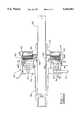
- FIG. 1is a generally schematic cross-sectional view illustrating the hydromechanical system of the invention
- FIG. 2Ais a view taken along line 2--2 of FIG. 1, illustrating the reversible hydraulic pump in a first position
- FIG. 2Bis a view taken along line 2--2 in FIG. 1, illustrating the reversible hydraulic pump in a second position;
- FIG. 3shows an alternate embodiment of the hydromechanical system according to the invention
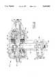
- FIG. 4is a cross-sectional view of a torque transfer case incorporating the hydromechanical system of the invention.
- FIG. 5is an enlarged, partial cross-sectional view of the hydromechanical system illustrated in FIG. 1.
- FIG. 1shows a simplified cross-sectional view of a driveline system having two differentially rotating shafts, including a first rotating shaft 50 and a second rotating shaft 52.
- the shafts 50 and 52are differentially driven and rotatable relative to one another, with shaft 52 being supported by bearings 54 relative to shaft 50.
- Shafts 50 and 52are selectively coupled together for rotation with one another by means of the differential speed limiting clutch generally indicated at 56.
- Clutch 56includes interleaved clutch plates 58 and 60, with plates 58 splined to rotate with a housing 62.
- the housing 62in turn is splined to shaft 52 for rotation therewith.
- Hydromechanical system 20includes a casing 70 coupled for rotation with shaft 50.
- a reversible hydraulic pump 72is disposed within the rotating housing 70.
- the hydraulic pump 72is a reversible gerotor pump.
- means to supply hydraulic fluid to the rotating housing 70are provided, such as a hydraulic fluid supply line 74 connected to a hydraulic fluid sump, and coupled to an intake manifold 76. Hydraulic fluid is supplied to a plenum 78 within manifold 76, and to pump 72 via a passage 80 in casing 70 to the inlet of pump 72.
- pump 72comprises an inner rotor 82 having a plurality of external teeth 84.
- Inner rotor 82is drivingly connected to rotating shaft member 50.
- the reversible gerotor pump 72also includes an outer rotor or impeller 86 having a plurality of internal teeth 88 which are in meshing engagement with external teeth 84 of inner rotor or impeller 82.
- the inner rotor 82has one less tooth than the outer rotor 86, such that driving of the inner rotor 82 will in turn cause driving of the outer rotor 86 which is free to rotate within an outer eccentric ring 90.
- Relative rotation of the inner rotor 82 to the outer rotor 86thus provides a series of variable volume chambers within pump 72, resulting in the build up of fluid pressure and pumping of hydraulic fluid in response to relative rotation of the rotors 82 and 86, and thus in response to differential rotation between shafts 50 and 52.
- the eccentric ring 90includes a flange 92 extending approximately 180 degrees around the periphery of ring 90, which cooperates with a stop pin 94 supported on casing 70.
- the pump 72is reversible, such that hydraulic fluid is pumped in response to differential rotation between shafts 50 and 52 in either direction. In FIG.
- the pumpis shown rotating in the direction of the arrow, such that rotation of ring 90 is stopped by the flange 92 contacting stop pin 94, and the external teeth 84 of inner rotor 82 meshingly engaged with the internal teeth 88 of outer rotor 86 at a top portion of the eccentric bore provided in ring 90. If the differential rotation of the shafts 50 and 52 is reversed, the outer ring 90 will rotate approximately 180 degrees, with stop pin 94 contacting flange 92 to stop rotation of ring 90. As shown in FIG. 2B, the eccentric bore in ring 90 is thus moved such that the external teeth 84 of inner rotor 82 meshingly engaged with internal teeth 88 of outer rotor 86 at a bottom portion thereof, with pumping capacity maintained.
- pump 72pumps hydraulic fluid in response to relative rotation between shafts 50 and 52 regardless of the relative rotation between these shafts.
- the preferred embodimentprovides inner rotor 82 and outer rotor 86 with seven teeth. Other arrangements are contemplated to provide proper pumping capacity for the desired application.
- the hydromechanical system 20further includes an annular piston 96 which is disposed within casing 70 and includes a guide member 98 and an actuating member 100 which slidingly engages guide member 98.
- Piston 96further includes a chamber 102 which is disposed between guide member 98 and actuating member 100 and receives the hydraulic fluid pumped from pump 72 via supply passage 104 formed in guide member 98.
- Guide member 98also provides support for stop pin 94.
- the actuating member 100 of piston 96also includes at least one restricted vent passage 106 and may comprise a plurality of vent passages 106 as shown in FIG. 2. Each vent passage 106 extends through piston actuating member 100 and is in flow communication with piston chamber 102.
- piston actuating member 100Also acting on piston actuating member 100 is an annular spring element 108 disposed between piston actuating member 100 and clutch 56.
- the spring member 108is an overcentering spring, such as a "finger washer” or wave spring, and restrains piston actuating member 100 from engagement with the clutch 56 until a predetermined actuating pressure is achieved which overcomes the restraining force of spring 108 and allows engagement of actuating member 100 with the clutch 56.
- this predetermined thresholdmay be set or tuned to a predetermined differential rotation between shafts 50 and 52, with the reversible hydraulic pump 72 providing pumping pressure corresponding to such differential rotation to actuate piston 96.
- the pressure of the hydraulic fluid supplied to chamber 102 from pump 72provides hydraulic force to actuate piston actuating member 100 upon reaching a predetermined differential rotation between shafts 50 and 52 which is sufficient to overcome the resisting force applied by spring 108. Accordingly, actuating member 100 is urged against clutch 56, which will in turn substantially close the vent passages 106. At this time, the hydraulic pressure in chamber 102 will increase very quickly in response to relative rotation between shafts 50 and 52, causing actuating member 100 to compress clutch plates 58 and 60 into frictional engagement with one another.
- the spring element 108as previously indicated, may be an overcentering type spring providing a nonlinear spring constant which exhibits nonlinear load versus deflection characteristics.
- spring 108may be a coil spring or similar type having a linear spring constant exhibiting linear load versus deflection characteristics. The choice of the type of spring element 108 is dependent upon the desired spring characteristic for particular application, and again allows tuning of the hydromechanical system 20 to perform in a desired manner for a particular application.
- reaction disc 110disposed on the opposite side of clutch pack 56 from the piston 96, including a portion 112 which is splined to shaft 52 for rotation therewith. Accordingly, when actuating member 100 of piston 96 applies an axial force to clutch 56, plates 58 and 60 will be urged into frictional engagement with one another, and the load applied to piston 96 is transferred to reaction disc 110 and correspondingly locks shafts 50 and 52 together. A snap ring 114 is secured to member 62 to maintain reaction disc 110 in proper abutting relationship to the clutch 56.
- Unloading of clutch 56may be accomplished by simply allowing hydraulic fluid to bleed from piston chamber 102 by means of machining intolerances formed in the components of the piston assembly 96 as an example. Machining intolerances may be specifically accepted to form gaps between the components of the piston assembly 96 in relation to clutch 56, with leakage of hydraulic fluid reducing hydraulic pressure to allow the clutch pack to slip after a predetermined time from actuation. Alternatively, as shown in FIG.
- one or more additional bleed passages 120may be formed through the piston actuating member 100 which communicate with bleed channels 122 formed on the outside of actuating member 100 adjacent clutch pack 56. Bleed passages 120 and bleed channels 122 provide restricted passage of hydraulic fluid from the piston chamber 102 to slowly bleed off hydraulic pressure established in the piston assembly 96 upon actuating clutch 56 in a desired manner. Other suitable arrangements to allow a predetermined reduction in hydraulic fluid pressure for deactuation of clutch 56 are contemplated in the invention.
- the hydromechanical system of the inventionis incorporated into a torque transfer case 10.
- the transfer case 10is merely an example of a vehicle drivetrain subassembly in which the hydromechanical system of the invention may be useful.
- the torque transfer case 10may be used in a four-wheel drive vehicle, for example, and includes an input shaft 12, which receives torque from an engine and transmission assembly (not shown) of the vehicle.
- a rear output shaft 14 and a front output shaft 16are connected to the rear and front drive shafts (not shown) of the vehicle to provide drive power thereto.
- An interaxle planetary gear differential generally indicated as 18may be used to divide torque from input shaft 12 between the rear output shaft 14 and front output shaft 16.
- the hydromechanical system for limiting differential speed between rotating members in the transfer case 10is generally shown at 20.
- the hydromechanical system 20does not inhibit differentiation between the output shaft 14 and 16 during normal vehicle operation; such as during cornering where differentiation between the output shafts 14 and 16 is required.
- the hydromechanical system 20limits the allowable differential speed between the rear output shaft 14 and front output shaft 16 to avoid excessive slippage between output shafts 14 and 16. Excessive slipping may occur between these output shafts when a front or rear wheel of the vehicle engages a surface having a low coefficient of friction, for example.
- the hydromechanical system 20 of the inventionhas the capacity to arrest relative rotation between the output shafts 14 and 16 should relative rotational speed exceed a predetermined or prespecified limit.
- the hydromechanical system 20also provides a mechanism by which torque may be transferred to a non-slipping axle upon the occurrence of predetermined differential rotation between the output shafts 14 and 16.
- the hydromechanical system 20also provides these desired functions without requiring continuous relative rotation between the output shafts, and without producing any undesirable torque transfer at relative rotational speeds below the prespecified limit.
- the torque transfer case 10 shown in FIG. 4is merely an example of a known torque transfer case, and the hydromechanical system 20 of the invention may be used with the variety of other known torque transfer cases, or wherever it is desired to limit differential rotation between two rotating members.
- the input shaft 12may be rotatably supported within a housing 22.
- the input shaft 12may be coupled through a planetary gear set 24 to an intermediate shaft 26 rotatably supported within housing 22.
- the planetary gear set 24may provide low and high speed ranges in operation of the transfer case 10.
- the intermediate shaft 26is coupled to and drives the planet carrier 28 of the interaxle planetary gear differential 18.
- Planet carrier 28carries a plurality of circumferentially spaced and individually rotatable planet gears 30.
- Each of the planet gears 30meshingly engages with the sun gear 32 and ring gear 34 of the planetary gear differential 18.
- the sun gear 32may be provided on a sleeve 36 rotatably mounted about intermediate shaft 26.
- the sleeve 36may in turn carry a drive sprocket 38.
- the ring gear 34 of the planetary gear differential 18is drivingly connected to a link gear 40, which in turn is drivingly coupled to the rear output shaft 14 to provide driving torque thereto.
- the torqueis transmitted from the vehicle engine and transmission to the input shaft 12 and through the planetary gear set 24 to the intermediate shaft 26.
- the intermediate shaft 26in turn drives the planet carrier 28 associated with the interaxle planetary gear differential, transmitting torque to the sun gear 32 and ring gear 34 thereof.
- Driving torqueis transmitted from the ring gear 34 to the rear output shaft 14, and through the sun gear 32 to drive sleeve 36 and the drive sprocket 38 associated therewith.
- the drive sprocket 38is connected to a drive chain 42 to drive a second sprocket 44. Torque is transferred from the drive sprocket 44 to the front output shaft 16 through a CV universal joint generally indicated at 46.
- a differential speed limiting clutch 48is provided to selectively lock ring gear 34 and sleeve 36 into rotation with one another, thereby arresting relative rotation between these members, and correspondingly between the rear output shaft 14 and front output shaft 16.
- the hydromechanical system 20is used to actuate the differential speed limiting clutch 48 if the relative rotational speed between these members exceeds a desired or prespecified limit.
- the hydromechanical system 20is autonomous, or self-controlled with the ability to tune or program the system to set the desired or prespecified limit according to desired driving conditions.
- FIG. 5shows an enlarged view of the interaxle planetary gear differential 18 which divides torque between front and rear axles of the four-wheel drive vehicle.
- input torqueis supplied via shaft 26, and is distributed to a rear output shaft 14 and sun gear 32 along with corresponding sleeve 36 via differential 18.
- the sleeve 36supplies torque to a drive sprocket 38 and drive chain 42 connected to a front output shaft 16 (shown in FIG. 4).
- the hydromechanical system 20is disposed within the transfer case housing, and housing 70 is coupled for rotation with ring gear 34, which in turn is coupled to the rear output shaft 14 through link gear 40.
- the reversible hydraulic pump 72has the outer eccentric ring 92 and outer rotor 86 coupled to housing 70 for rotation therewith, and thus for rotation with output shaft 14.
- the inner rotor 82is coupled for rotation with sleeve 36, and thus with front output shaft 16 (not shown).
- the hydraulic pump 72does not operate to pump hydraulic fluid, and piston 96 does not actuate the differential speed limiting clutch 48 forming a part of the interaxle planetary gear differential 18.
- hydromechanical system 20allows such differential rotation without actuating clutch 48.
- differential rotationwill cause hydraulic pump 72 to pump fluid in response thereto, the restraining force of spring member 108 prevents actuation of clutch 48. Accordingly, during normal driving conditions, virtually no axial force is applied to clutch 48, allowing planetary gear differential 18 to perform in a normal manner.
- the hydromechanical system 20 of the inventionselectively couples the first and second rotating members in the transfer case 10 to one another to eliminate differentiation therebetween, while avoiding any limitation to differentiation required during normal vehicle driving conditions.
- the hydromechanical system 20has the capacity to arrest relative rotation should the relative rotational speed between the two rotating members of the vehicle drivetrain exceed a predetermined limit, thereby providing an autonomous mechanical mechanism for limiting relative rotational speed between two driveline components.
- the hydromechanical system 20is self-contained and exerts negligible force below the predetermined differential rotational speed and then quickly provides a force sufficient to arrest differential rotation between the members once this predetermined limit is met.
- the hydromechanical system 20 of the inventionmay also be used in other environments, such as in a vehicle differential to limit differential rotation of output shafts associated with the differential. Again in this environment, the outer wheel of the vehicle must rotate faster than the inner wheel during turning, with the differential gear maintaining equally divided torque distribution to the wheels to secure a smooth turn. On the other hand, if a vehicle wheel is on a low friction surface, a limited slip differential is desirable to transfer torque from the slipping wheel to a non-slipping wheel to improve driving mobility.
- the hydromechanical system 20 of the present inventionallows differential rotation between the output shafts of the differential to be limited according to differential speed between the output shafts, or based upon differential torque supplied to the output shafts.
Landscapes
- Engineering & Computer Science (AREA)
- General Engineering & Computer Science (AREA)
- Mechanical Engineering (AREA)
- Chemical & Material Sciences (AREA)
- Combustion & Propulsion (AREA)
- Transportation (AREA)
- Physics & Mathematics (AREA)
- Fluid Mechanics (AREA)
- Arrangement And Driving Of Transmission Devices (AREA)
- Retarders (AREA)
- Hydraulic Clutches, Magnetic Clutches, Fluid Clutches, And Fluid Joints (AREA)
- Motor Power Transmission Devices (AREA)
Abstract
Description
Claims (12)
Priority Applications (5)
| Application Number | Priority Date | Filing Date | Title |
|---|---|---|---|
| US08/430,503US5655983A (en) | 1995-04-28 | 1995-04-28 | Hydromechanical system for limiting differential speed between differentially rotating members |
| JP8122775AJPH08318748A (en) | 1995-04-28 | 1996-04-22 | Fluid mechanical type system limiting differential speed between first and second rotary member |
| DE19616826ADE19616826A1 (en) | 1995-04-28 | 1996-04-26 | Hydromechanical system to limit speed variation between rotating parts of vehicle drive |
| US08/910,303US5916052A (en) | 1995-04-28 | 1997-08-11 | Hydromechanical system for limiting differential speed between differentially rotating members |
| JP2006284227AJP2007085551A (en) | 1995-04-28 | 2006-10-18 | Transfer case for four-wheel drive car |
Applications Claiming Priority (1)
| Application Number | Priority Date | Filing Date | Title |
|---|---|---|---|
| US08/430,503US5655983A (en) | 1995-04-28 | 1995-04-28 | Hydromechanical system for limiting differential speed between differentially rotating members |
Related Child Applications (1)
| Application Number | Title | Priority Date | Filing Date |
|---|---|---|---|
| US08/910,303ContinuationUS5916052A (en) | 1995-04-28 | 1997-08-11 | Hydromechanical system for limiting differential speed between differentially rotating members |
Publications (1)
| Publication Number | Publication Date |
|---|---|
| US5655983Atrue US5655983A (en) | 1997-08-12 |
Family
ID=23707821
Family Applications (2)
| Application Number | Title | Priority Date | Filing Date |
|---|---|---|---|
| US08/430,503Expired - Fee RelatedUS5655983A (en) | 1995-04-28 | 1995-04-28 | Hydromechanical system for limiting differential speed between differentially rotating members |
| US08/910,303Expired - LifetimeUS5916052A (en) | 1995-04-28 | 1997-08-11 | Hydromechanical system for limiting differential speed between differentially rotating members |
Family Applications After (1)
| Application Number | Title | Priority Date | Filing Date |
|---|---|---|---|
| US08/910,303Expired - LifetimeUS5916052A (en) | 1995-04-28 | 1997-08-11 | Hydromechanical system for limiting differential speed between differentially rotating members |
Country Status (3)
| Country | Link |
|---|---|
| US (2) | US5655983A (en) |
| JP (2) | JPH08318748A (en) |
| DE (1) | DE19616826A1 (en) |
Cited By (18)
| Publication number | Priority date | Publication date | Assignee | Title |
|---|---|---|---|---|
| US5785622A (en)* | 1994-02-02 | 1998-07-28 | Slim Borgudd | Differential gear |
| US5901802A (en)* | 1996-05-17 | 1999-05-11 | Nissan Motor Co., Ltd. | Hydraulic passages for oil pump for speed reducer used in electric vehicles |
| US5916052A (en)* | 1995-04-28 | 1999-06-29 | Dana Corporation | Hydromechanical system for limiting differential speed between differentially rotating members |
| US6001040A (en) | 1998-02-25 | 1999-12-14 | Auburn Gear, Inc. | Hydraulically operated limited slip differential |
| US6095939A (en)* | 1998-12-09 | 2000-08-01 | New Venture Gear, Inc. | Differential for vehicular power transfer systems |
| US6161643A (en)* | 1997-12-10 | 2000-12-19 | Daimlerchrysler Corporation | System of controlling torque transfer in a motor vehicle and related method |
| US20030111285A1 (en)* | 2001-12-18 | 2003-06-19 | Philip Gansloser | Longitudinally installed power train and method of making a power train |
| US6662684B1 (en) | 2000-07-20 | 2003-12-16 | Torque-Traction Technologies, Inc. | Single-piece transfer case housing assembly |
| EP1378687A3 (en)* | 2002-07-01 | 2005-03-09 | Dana Corporation | Lubrication pump for inter-axle differential |
| US20060258501A1 (en)* | 2003-11-18 | 2006-11-16 | Hans Wormsbaecher | Torque transfer device having a constant velocity joint output |
| US20110226578A1 (en)* | 2010-03-22 | 2011-09-22 | Matthew George Fox | Hydraulic coupling having improved hydraulic porting path design |
| US20150027253A1 (en)* | 2012-02-06 | 2015-01-29 | Hunan Sany Intelligent Control Equipment Co., Ltd. | Power Gear-Shifting Transmission and Engineering Machinery |
| US20160116046A1 (en)* | 2014-10-23 | 2016-04-28 | Jaguar Land Rover Limited | Transfer case |
| US9511667B2 (en)* | 2015-02-27 | 2016-12-06 | Caterpillar Inc. | Output transfer group for mobile machine powertrain |
| US9541183B2 (en)* | 2015-02-27 | 2017-01-10 | Caterpiller Inc. | Output transfer group for mobile machine powertrain |
| US10093180B2 (en)* | 2015-07-30 | 2018-10-09 | Mazda Motor Corporation | Transfer device for four-wheel drive vehicle |
| CN112049868A (en)* | 2020-09-27 | 2020-12-08 | 西安煤矿机械有限公司 | Clutch for coal shearer and control method thereof |
| EP3981996A1 (en)* | 2020-09-29 | 2022-04-13 | Deere & Company | Assembly for releasing a coupling connection of a hydraulic quick coupler |
Families Citing this family (24)
| Publication number | Priority date | Publication date | Assignee | Title |
|---|---|---|---|---|
| CA2276643A1 (en)* | 1999-06-23 | 2000-12-23 | Bombardier Inc. | Straddle-type all-terrain vehicle with progressive differential |
| US6474433B1 (en)* | 1999-12-10 | 2002-11-05 | Spicer Technology Inc. | Speed sensitive on-demand torque coupling differential |
| US6882922B2 (en)* | 2000-10-11 | 2005-04-19 | Visteon Global Technologies, Inc. | Torque-biasing system |
| US6859715B2 (en) | 2000-10-11 | 2005-02-22 | Visteon Global Technologies, Inc. | Torque-biasing system |
| US6855083B1 (en)* | 2001-01-18 | 2005-02-15 | Dana Corporation | Lubrication pump for inter-axle differential |
| US6544137B2 (en) | 2001-07-18 | 2003-04-08 | Visteon Global Technologies, Inc. | Differential device |
| US6544136B2 (en) | 2001-07-18 | 2003-04-08 | Visteon Global Technologies, Inc. | Differential device |
| US6591714B2 (en) | 2001-07-18 | 2003-07-15 | Visteon Global Technologies, Inc. | Coupling device |
| US6681913B2 (en) | 2001-07-18 | 2004-01-27 | Visteon Global Technologies, Inc. | Coupling device |
| US6575281B2 (en) | 2001-07-18 | 2003-06-10 | Visteon Global Technologies, Inc. | Coupling device |
| WO2005019687A2 (en)* | 2003-08-20 | 2005-03-03 | Synkinetics, Inc. | Yaw control differential system |
| US7186199B1 (en) | 2004-10-29 | 2007-03-06 | Torque-Traction Technologies. Llc. | Torque vectoring gear drive apparatus |
| US20060105883A1 (en)* | 2004-11-15 | 2006-05-18 | James Krisher | Transfer case with variably controlled torque coupling device |
| US7318511B2 (en)* | 2005-06-27 | 2008-01-15 | Eaton Corporation | Coupling device independent of differential speed |
| JP2008185071A (en)* | 2007-01-26 | 2008-08-14 | Gkn ドライブライン トルクテクノロジー株式会社 | Power transmission device |
| US8388487B2 (en)* | 2008-06-05 | 2013-03-05 | Jtekt Corporation | Differential apparatus for vehicle |
| US8608611B2 (en)* | 2009-01-21 | 2013-12-17 | Magna Powertrain Of America, Inc. | AWD vehicle with disconnect system |
| US8387740B2 (en)* | 2009-06-24 | 2013-03-05 | Thomas W. Melcher | Motor vehicle with differential gear box providing angular movement and method therefor |
| CN101934728B (en)* | 2010-09-30 | 2012-11-21 | 无锡英特帕普威孚液压有限责任公司 | Static hydraulic transmission case |
| KR20140086054A (en)* | 2012-12-28 | 2014-07-08 | 현대위아 주식회사 | Range shift system for transfer case |
| US10137965B2 (en) | 2013-02-28 | 2018-11-27 | Thomas W. Melcher | Snowmobile with leaning capability and improvements therefor |
| US9545976B2 (en) | 2013-02-28 | 2017-01-17 | Thomas W. Melcher | Snowmobile with leaning capability |
| US10598292B2 (en) | 2016-05-06 | 2020-03-24 | Thomas W. Melcher | Hydraulic bypass system |
| US11920664B2 (en) | 2022-06-30 | 2024-03-05 | Bombardier Recreational Products Inc. | Limited-slip differential system |
Citations (16)
| Publication number | Priority date | Publication date | Assignee | Title |
|---|---|---|---|---|
| US3657935A (en)* | 1962-02-14 | 1972-04-25 | Loren J O Brien | Differential transmission |
| US3748928A (en)* | 1971-09-20 | 1973-07-31 | Borg Warner | Control system for mutiple driving axle vehicle |
| US3894446A (en)* | 1974-06-03 | 1975-07-15 | Twin Disc Inc | Power transmission having friction clutch bias differential with automatic clutch release |
| US3990327A (en)* | 1975-01-08 | 1976-11-09 | Ford Motor Company | Multiple range hydrostatic transmission mechanism |
| US4012968A (en)* | 1974-12-23 | 1977-03-22 | Borg-Warner Corporation | Speed-sensitive differential mechanism |
| US4353269A (en)* | 1979-03-30 | 1982-10-12 | Mannesmann Aktiengesellschaft | Ship's transmission with changeover from cruising speed to slow speed |
| US4727966A (en)* | 1984-05-30 | 1988-03-01 | Mitsubishi Jidosha Kogyo Kabushiki Kaisha | Differential with differential motion limiting mechanism |
| US4730514A (en)* | 1985-04-22 | 1988-03-15 | Mitsubishi Jidosha Kogyo Kabushiki Kaisha | Differential speed limiting device mechanism |
| US4743180A (en)* | 1985-12-09 | 1988-05-10 | Schwabische Huttenwerke Gmbh | Reversible gear-type pump |
| US4781078A (en)* | 1987-02-02 | 1988-11-01 | Dana Corporation | Locking differential with electromagnetic actuated clutch |
| US5217416A (en)* | 1992-04-17 | 1993-06-08 | Dana Corporation | Lock up/limited slip differential |
| US5310388A (en)* | 1993-02-10 | 1994-05-10 | Asha Corporation | Vehicle drivetrain hydraulic coupling |
| US5320586A (en)* | 1992-12-31 | 1994-06-14 | Dana Corporation | Locking limited slip planetary transfer case |
| US5494421A (en)* | 1991-12-27 | 1996-02-27 | Mitsubishi Denki Kabushiki Kaisha | Scroll compressor having a gear oil pump accommodating reverse rotation |
| US5501585A (en)* | 1993-11-26 | 1996-03-26 | Aisin Seiki Kabushiki Kaisha | Oil pump having a sealing mechanism for a pumping chamber |
| US5536215A (en)* | 1993-02-10 | 1996-07-16 | Asha Corporation | Hydraulic coupling for vehicle drivetrain |
Family Cites Families (11)
| Publication number | Priority date | Publication date | Assignee | Title |
|---|---|---|---|---|
| US4677873A (en)* | 1985-12-23 | 1987-07-07 | Chrysler Motors Corporation | Transfer case with inter-axle dual-planetary differential |
| WO1993019310A1 (en)* | 1992-03-20 | 1993-09-30 | Asha Corporation | Vehicle drivetrain hydraulic coupling |
| US5334116A (en)* | 1992-12-31 | 1994-08-02 | Dana Corporation | All wheel drive transfer case having two wheel overdrive |
| US5655983A (en)* | 1995-04-28 | 1997-08-12 | Dana Corporation | Hydromechanical system for limiting differential speed between differentially rotating members |
| US5725453A (en)* | 1995-08-17 | 1998-03-10 | New Venture Gear, Inc. | On-demand double offset transfer case |
| US5702319A (en)* | 1995-10-13 | 1997-12-30 | Dana Corporation | Hydromechanical system for limiting differential speed between differentially rotating members |
| US5651749A (en)* | 1996-02-13 | 1997-07-29 | New Venture Gear, Inc. | Full-time transfer case with synchronized dual planetary gear reduction unit |
| US5697861A (en)* | 1996-02-13 | 1997-12-16 | New Venture Gear, Inc. | Full-time transfer case with synchronized layshaft-type range shift arrangement |
| US5704863A (en)* | 1996-07-01 | 1998-01-06 | New Venture Gear, Inc. | Two-speed transfer case with on-demand torque control having a coupling pump and a supply pump |
| US5704867A (en)* | 1996-07-16 | 1998-01-06 | New Venture Gear, Inc. | Full-time transfer case with synchronized range shift arrangement |
| US5738604A (en)* | 1996-07-30 | 1998-04-14 | Dana Corporation | Four-wheel motor vehicle drive transfer case with limited differentiation |
- 1995
- 1995-04-28USUS08/430,503patent/US5655983A/ennot_activeExpired - Fee Related
- 1996
- 1996-04-22JPJP8122775Apatent/JPH08318748A/enactivePending
- 1996-04-26DEDE19616826Apatent/DE19616826A1/ennot_activeWithdrawn
- 1997
- 1997-08-11USUS08/910,303patent/US5916052A/ennot_activeExpired - Lifetime
- 2006
- 2006-10-18JPJP2006284227Apatent/JP2007085551A/enactivePending
Patent Citations (16)
| Publication number | Priority date | Publication date | Assignee | Title |
|---|---|---|---|---|
| US3657935A (en)* | 1962-02-14 | 1972-04-25 | Loren J O Brien | Differential transmission |
| US3748928A (en)* | 1971-09-20 | 1973-07-31 | Borg Warner | Control system for mutiple driving axle vehicle |
| US3894446A (en)* | 1974-06-03 | 1975-07-15 | Twin Disc Inc | Power transmission having friction clutch bias differential with automatic clutch release |
| US4012968A (en)* | 1974-12-23 | 1977-03-22 | Borg-Warner Corporation | Speed-sensitive differential mechanism |
| US3990327A (en)* | 1975-01-08 | 1976-11-09 | Ford Motor Company | Multiple range hydrostatic transmission mechanism |
| US4353269A (en)* | 1979-03-30 | 1982-10-12 | Mannesmann Aktiengesellschaft | Ship's transmission with changeover from cruising speed to slow speed |
| US4727966A (en)* | 1984-05-30 | 1988-03-01 | Mitsubishi Jidosha Kogyo Kabushiki Kaisha | Differential with differential motion limiting mechanism |
| US4730514A (en)* | 1985-04-22 | 1988-03-15 | Mitsubishi Jidosha Kogyo Kabushiki Kaisha | Differential speed limiting device mechanism |
| US4743180A (en)* | 1985-12-09 | 1988-05-10 | Schwabische Huttenwerke Gmbh | Reversible gear-type pump |
| US4781078A (en)* | 1987-02-02 | 1988-11-01 | Dana Corporation | Locking differential with electromagnetic actuated clutch |
| US5494421A (en)* | 1991-12-27 | 1996-02-27 | Mitsubishi Denki Kabushiki Kaisha | Scroll compressor having a gear oil pump accommodating reverse rotation |
| US5217416A (en)* | 1992-04-17 | 1993-06-08 | Dana Corporation | Lock up/limited slip differential |
| US5320586A (en)* | 1992-12-31 | 1994-06-14 | Dana Corporation | Locking limited slip planetary transfer case |
| US5310388A (en)* | 1993-02-10 | 1994-05-10 | Asha Corporation | Vehicle drivetrain hydraulic coupling |
| US5536215A (en)* | 1993-02-10 | 1996-07-16 | Asha Corporation | Hydraulic coupling for vehicle drivetrain |
| US5501585A (en)* | 1993-11-26 | 1996-03-26 | Aisin Seiki Kabushiki Kaisha | Oil pump having a sealing mechanism for a pumping chamber |
Cited By (25)
| Publication number | Priority date | Publication date | Assignee | Title |
|---|---|---|---|---|
| US5785622A (en)* | 1994-02-02 | 1998-07-28 | Slim Borgudd | Differential gear |
| US5916052A (en)* | 1995-04-28 | 1999-06-29 | Dana Corporation | Hydromechanical system for limiting differential speed between differentially rotating members |
| US5901802A (en)* | 1996-05-17 | 1999-05-11 | Nissan Motor Co., Ltd. | Hydraulic passages for oil pump for speed reducer used in electric vehicles |
| US6161643A (en)* | 1997-12-10 | 2000-12-19 | Daimlerchrysler Corporation | System of controlling torque transfer in a motor vehicle and related method |
| US6001040A (en) | 1998-02-25 | 1999-12-14 | Auburn Gear, Inc. | Hydraulically operated limited slip differential |
| US6095939A (en)* | 1998-12-09 | 2000-08-01 | New Venture Gear, Inc. | Differential for vehicular power transfer systems |
| US6662684B1 (en) | 2000-07-20 | 2003-12-16 | Torque-Traction Technologies, Inc. | Single-piece transfer case housing assembly |
| US20030111285A1 (en)* | 2001-12-18 | 2003-06-19 | Philip Gansloser | Longitudinally installed power train and method of making a power train |
| EP1378687A3 (en)* | 2002-07-01 | 2005-03-09 | Dana Corporation | Lubrication pump for inter-axle differential |
| US7419434B2 (en) | 2003-11-18 | 2008-09-02 | Gkn Driveline North America, Inc. | Torque transfer device having a constant velocity joint output |
| US20070238535A1 (en)* | 2003-11-18 | 2007-10-11 | Hans Wormsbaecher | Torque Transfer Device Having A Constant Velocity Joint Output |
| US20060258501A1 (en)* | 2003-11-18 | 2006-11-16 | Hans Wormsbaecher | Torque transfer device having a constant velocity joint output |
| US7252616B2 (en) | 2003-11-18 | 2007-08-07 | Gkn Driveline North America, Inc. | Torque transfer device having a constant velocity joint output |
| US20110226578A1 (en)* | 2010-03-22 | 2011-09-22 | Matthew George Fox | Hydraulic coupling having improved hydraulic porting path design |
| US8579752B2 (en) | 2010-03-22 | 2013-11-12 | Eaton Corporation | Hydraulic coupling having improved hydraulic porting path design |
| US9447870B2 (en)* | 2012-02-06 | 2016-09-20 | Hunan Sany Intelligent Control Equipment Co., Ltd. | Power gear-shifting transmission and engineering machinery |
| US20150027253A1 (en)* | 2012-02-06 | 2015-01-29 | Hunan Sany Intelligent Control Equipment Co., Ltd. | Power Gear-Shifting Transmission and Engineering Machinery |
| US20160116046A1 (en)* | 2014-10-23 | 2016-04-28 | Jaguar Land Rover Limited | Transfer case |
| US9958048B2 (en)* | 2014-10-23 | 2018-05-01 | Jaguar Land Rover Limited | Transfer case |
| US9511667B2 (en)* | 2015-02-27 | 2016-12-06 | Caterpillar Inc. | Output transfer group for mobile machine powertrain |
| US9541183B2 (en)* | 2015-02-27 | 2017-01-10 | Caterpiller Inc. | Output transfer group for mobile machine powertrain |
| US10093180B2 (en)* | 2015-07-30 | 2018-10-09 | Mazda Motor Corporation | Transfer device for four-wheel drive vehicle |
| CN112049868A (en)* | 2020-09-27 | 2020-12-08 | 西安煤矿机械有限公司 | Clutch for coal shearer and control method thereof |
| EP3981996A1 (en)* | 2020-09-29 | 2022-04-13 | Deere & Company | Assembly for releasing a coupling connection of a hydraulic quick coupler |
| US11959575B2 (en) | 2020-09-29 | 2024-04-16 | Deere & Company | Arrangement for releasing a coupling connection of a hydraulic quick coupler |
Also Published As
| Publication number | Publication date |
|---|---|
| JPH08318748A (en) | 1996-12-03 |
| JP2007085551A (en) | 2007-04-05 |
| DE19616826A1 (en) | 1996-10-31 |
| US5916052A (en) | 1999-06-29 |
Similar Documents
| Publication | Publication Date | Title |
|---|---|---|
| US5655983A (en) | Hydromechanical system for limiting differential speed between differentially rotating members | |
| JP2007085551A6 (en) | Transfer case for four-wheel drive vehicles | |
| US5938556A (en) | Differential speed-sensitive and torque-sensitive limited slip coupling | |
| US6814681B2 (en) | On-demand all-wheel drive system | |
| US6953411B2 (en) | Electronically-tuned hydromechanical coupling | |
| US4727966A (en) | Differential with differential motion limiting mechanism | |
| US6145644A (en) | Multi-function control valve for hydraulic coupling | |
| US6378682B1 (en) | Multi-function control valve for hydraulic coupling | |
| US6942055B2 (en) | Electronically-controlled rear module for all-wheel drive system | |
| US6668961B2 (en) | Full-time all-wheel drive power take-off unit for motor vehicle | |
| EP0063432B1 (en) | Controlled differential | |
| US6041903A (en) | Hydraulic coupling for vehicular power transfer systems | |
| CA2465280C (en) | Rear drive module for all-wheel drive vehicle | |
| US6112874A (en) | Hydromechanical coupling with torque-limiting and temperature-sensitive unloading features | |
| US5702319A (en) | Hydromechanical system for limiting differential speed between differentially rotating members | |
| US6168545B1 (en) | Limited slip differential with spring-loaded clutches | |
| US5456642A (en) | Geared traction unit | |
| EP2550467B1 (en) | Hydraulic coupling having improved hydraulic porting path design | |
| CA2672950C (en) | Hydraulic coupling |
Legal Events
| Date | Code | Title | Description |
|---|---|---|---|
| AS | Assignment | Owner name:DANA CORPORATION, OHIO Free format text:ASSIGNMENT OF ASSIGNORS INTEREST;ASSIGNOR:DICK, JOSEPH A.;REEL/FRAME:007569/0843 Effective date:19950705 | |
| FEPP | Fee payment procedure | Free format text:PAYOR NUMBER ASSIGNED (ORIGINAL EVENT CODE: ASPN); ENTITY STATUS OF PATENT OWNER: LARGE ENTITY | |
| AS | Assignment | Owner name:SPICER TECHNOLOGY, INC., INDIANA Free format text:ASSIGNMENT OF ASSIGNORS INTEREST;ASSIGNOR:DANA CORPORATION;REEL/FRAME:010609/0413 Effective date:19991228 | |
| AS | Assignment | Owner name:SPICER TECHNOLOGY, INC., INDIANA Free format text:ASSIGNMENT OF ASSIGNORS INTEREST;ASSIGNOR:DANA CORPORATION;REEL/FRAME:010776/0646 Effective date:19991228 | |
| FPAY | Fee payment | Year of fee payment:4 | |
| AS | Assignment | Owner name:TORQUE-TRACTION TECHNOLOGIES, INC., OHIO Free format text:MERGER /CHANGE OF NAME;ASSIGNORS:SPICER TECHNOLOGY, INC.;SPICER DRIVESHAFT, INC.;REEL/FRAME:014646/0285 Effective date:20021231 Owner name:TORQUE-TRACTION TECHNOLOGIES, INC., OHIO Free format text:MERGER AND CHANGE OF NAME;ASSIGNORS:SPICER TECHNOLOGY, INC.;SPICER DRIVESHAFT, INC.;REEL/FRAME:013943/0214 Effective date:20021231 | |
| FPAY | Fee payment | Year of fee payment:8 | |
| AS | Assignment | Owner name:TORQUE-TRACTION TECHNOLOGIES LLC, OHIO Free format text:MERGER;ASSIGNOR:TORQUE-TRACTION TECHNOLOGY, INC.;REEL/FRAME:017240/0209 Effective date:20060101 | |
| AS | Assignment | Owner name:DANA AUTOMOTIVE SYSTEMS GROUP, LLC, OHIO Free format text:ASSIGNMENT OF ASSIGNORS INTEREST;ASSIGNOR:TORQUE-TRACTION TECHNOLOGIES, LLC;REEL/FRAME:020518/0949 Effective date:20080131 Owner name:DANA AUTOMOTIVE SYSTEMS GROUP, LLC,OHIO Free format text:ASSIGNMENT OF ASSIGNORS INTEREST;ASSIGNOR:TORQUE-TRACTION TECHNOLOGIES, LLC;REEL/FRAME:020518/0949 Effective date:20080131 | |
| AS | Assignment | Owner name:CITICORP USA, INC., NEW YORK Free format text:INTELLECTUAL PROPERTY TERM FACILITY SECURITY AGREEMENT;ASSIGNORS:DANA HOLDING CORPORATION;DANA LIMITED;DANA AUTOMOTIVE SYSTEMS GROUP, LLC;AND OTHERS;REEL/FRAME:020859/0359 Effective date:20080131 Owner name:CITICORP USA, INC., NEW YORK Free format text:INTELLECTUAL PROPERTY REVOLVING FACILITY SECURITY AGREEMENT;ASSIGNORS:DANA HOLDING CORPORATION;DANA LIMITED;DANA AUTOMOTIVE SYSTEMS GROUP, LLC;AND OTHERS;REEL/FRAME:020859/0249 Effective date:20080131 Owner name:CITICORP USA, INC.,NEW YORK Free format text:INTELLECTUAL PROPERTY REVOLVING FACILITY SECURITY AGREEMENT;ASSIGNORS:DANA HOLDING CORPORATION;DANA LIMITED;DANA AUTOMOTIVE SYSTEMS GROUP, LLC;AND OTHERS;REEL/FRAME:020859/0249 Effective date:20080131 Owner name:CITICORP USA, INC.,NEW YORK Free format text:INTELLECTUAL PROPERTY TERM FACILITY SECURITY AGREEMENT;ASSIGNORS:DANA HOLDING CORPORATION;DANA LIMITED;DANA AUTOMOTIVE SYSTEMS GROUP, LLC;AND OTHERS;REEL/FRAME:020859/0359 Effective date:20080131 | |
| REMI | Maintenance fee reminder mailed | ||
| LAPS | Lapse for failure to pay maintenance fees | ||
| LAPS | Lapse for failure to pay maintenance fees | Free format text:PATENT EXPIRED FOR FAILURE TO PAY MAINTENANCE FEES (ORIGINAL EVENT CODE: EXP.); ENTITY STATUS OF PATENT OWNER: LARGE ENTITY | |
| STCH | Information on status: patent discontinuation | Free format text:PATENT EXPIRED DUE TO NONPAYMENT OF MAINTENANCE FEES UNDER 37 CFR 1.362 | |
| FP | Lapsed due to failure to pay maintenance fee | Effective date:20090812 |