US5655832A - Multiple wavelength light processor - Google Patents
Multiple wavelength light processorDownload PDFInfo
- Publication number
- US5655832A US5655832AUS08/445,892US44589295AUS5655832AUS 5655832 AUS5655832 AUS 5655832AUS 44589295 AUS44589295 AUS 44589295AUS 5655832 AUS5655832 AUS 5655832A
- Authority
- US
- United States
- Prior art keywords
- light
- radiant energy
- sources
- combination
- lens
- Prior art date
- Legal status (The legal status is an assumption and is not a legal conclusion. Google has not performed a legal analysis and makes no representation as to the accuracy of the status listed.)
- Expired - Lifetime
Links
- 230000003287optical effectEffects0.000claimsabstractdescription18
- 239000000126substanceSubstances0.000claimsdescription2
- 210000000887faceAnatomy0.000description39
- 230000005855radiationEffects0.000description12
- 239000000463materialSubstances0.000description10
- 238000005286illuminationMethods0.000description6
- 239000007788liquidSubstances0.000description5
- 238000000034methodMethods0.000description5
- XLYOFNOQVPJJNP-UHFFFAOYSA-NwaterSubstancesOXLYOFNOQVPJJNP-UHFFFAOYSA-N0.000description5
- 238000010276constructionMethods0.000description3
- 230000000694effectsEffects0.000description3
- 238000004519manufacturing processMethods0.000description3
- 239000007787solidSubstances0.000description3
- 238000005452bendingMethods0.000description2
- 239000012530fluidSubstances0.000description2
- 239000011521glassSubstances0.000description2
- 239000000203mixtureSubstances0.000description2
- 239000002991molded plasticSubstances0.000description2
- 239000004033plasticSubstances0.000description2
- 229910052710siliconInorganic materials0.000description2
- 239000010703siliconSubstances0.000description2
- 239000012780transparent materialSubstances0.000description2
- 238000001069Raman spectroscopyMethods0.000description1
- 230000004075alterationEffects0.000description1
- XAGFODPZIPBFFR-UHFFFAOYSA-NaluminiumChemical compound[Al]XAGFODPZIPBFFR-UHFFFAOYSA-N0.000description1
- 229910052782aluminiumInorganic materials0.000description1
- 238000003491arrayMethods0.000description1
- 230000000903blocking effectEffects0.000description1
- 238000011109contaminationMethods0.000description1
- 238000005260corrosionMethods0.000description1
- 230000007797corrosionEffects0.000description1
- 230000008878couplingEffects0.000description1
- 238000010168coupling processMethods0.000description1
- 238000005859coupling reactionMethods0.000description1
- 238000010586diagramMethods0.000description1
- 230000005611electricityEffects0.000description1
- 230000004907fluxEffects0.000description1
- PCHJSUWPFVWCPO-UHFFFAOYSA-NgoldChemical compound[Au]PCHJSUWPFVWCPO-UHFFFAOYSA-N0.000description1
- 239000010931goldSubstances0.000description1
- 229910052737goldInorganic materials0.000description1
- 230000005484gravityEffects0.000description1
- 238000010438heat treatmentMethods0.000description1
- 238000002347injectionMethods0.000description1
- 239000007924injectionSubstances0.000description1
- 239000004973liquid crystal related substanceSubstances0.000description1
- 239000011159matrix materialSubstances0.000description1
- 230000007246mechanismEffects0.000description1
- 238000000465mouldingMethods0.000description1
- 230000001681protective effectEffects0.000description1
- 210000001747pupilAnatomy0.000description1
- 238000002310reflectometryMethods0.000description1
- 238000001228spectrumMethods0.000description1
- 239000010409thin filmSubstances0.000description1
- 230000007704transitionEffects0.000description1
Images


Classifications
- F—MECHANICAL ENGINEERING; LIGHTING; HEATING; WEAPONS; BLASTING
- F21—LIGHTING
- F21V—FUNCTIONAL FEATURES OR DETAILS OF LIGHTING DEVICES OR SYSTEMS THEREOF; STRUCTURAL COMBINATIONS OF LIGHTING DEVICES WITH OTHER ARTICLES, NOT OTHERWISE PROVIDED FOR
- F21V7/00—Reflectors for light sources
- F21V7/0091—Reflectors for light sources using total internal reflection
- F—MECHANICAL ENGINEERING; LIGHTING; HEATING; WEAPONS; BLASTING
- F21—LIGHTING
- F21V—FUNCTIONAL FEATURES OR DETAILS OF LIGHTING DEVICES OR SYSTEMS THEREOF; STRUCTURAL COMBINATIONS OF LIGHTING DEVICES WITH OTHER ARTICLES, NOT OTHERWISE PROVIDED FOR
- F21V5/00—Refractors for light sources
- F21V5/04—Refractors for light sources of lens shape
- F—MECHANICAL ENGINEERING; LIGHTING; HEATING; WEAPONS; BLASTING
- F24—HEATING; RANGES; VENTILATING
- F24S—SOLAR HEAT COLLECTORS; SOLAR HEAT SYSTEMS
- F24S23/00—Arrangements for concentrating solar-rays for solar heat collectors
- F—MECHANICAL ENGINEERING; LIGHTING; HEATING; WEAPONS; BLASTING
- F24—HEATING; RANGES; VENTILATING
- F24S—SOLAR HEAT COLLECTORS; SOLAR HEAT SYSTEMS
- F24S23/00—Arrangements for concentrating solar-rays for solar heat collectors
- F24S23/30—Arrangements for concentrating solar-rays for solar heat collectors with lenses
- F24S23/31—Arrangements for concentrating solar-rays for solar heat collectors with lenses having discontinuous faces, e.g. Fresnel lenses
- F—MECHANICAL ENGINEERING; LIGHTING; HEATING; WEAPONS; BLASTING
- F24—HEATING; RANGES; VENTILATING
- F24S—SOLAR HEAT COLLECTORS; SOLAR HEAT SYSTEMS
- F24S23/00—Arrangements for concentrating solar-rays for solar heat collectors
- F24S23/70—Arrangements for concentrating solar-rays for solar heat collectors with reflectors
- G—PHYSICS
- G02—OPTICS
- G02B—OPTICAL ELEMENTS, SYSTEMS OR APPARATUS
- G02B17/00—Systems with reflecting surfaces, with or without refracting elements
- G02B17/006—Systems in which light light is reflected on a plurality of parallel surfaces, e.g. louvre mirrors, total internal reflection [TIR] lenses
- G—PHYSICS
- G02—OPTICS
- G02B—OPTICAL ELEMENTS, SYSTEMS OR APPARATUS
- G02B19/00—Condensers, e.g. light collectors or similar non-imaging optics
- G02B19/0004—Condensers, e.g. light collectors or similar non-imaging optics characterised by the optical means employed
- G02B19/0028—Condensers, e.g. light collectors or similar non-imaging optics characterised by the optical means employed refractive and reflective surfaces, e.g. non-imaging catadioptric systems
- G—PHYSICS
- G02—OPTICS
- G02B—OPTICAL ELEMENTS, SYSTEMS OR APPARATUS
- G02B19/00—Condensers, e.g. light collectors or similar non-imaging optics
- G02B19/0033—Condensers, e.g. light collectors or similar non-imaging optics characterised by the use
- G02B19/0038—Condensers, e.g. light collectors or similar non-imaging optics characterised by the use for use with ambient light
- G02B19/0042—Condensers, e.g. light collectors or similar non-imaging optics characterised by the use for use with ambient light for use with direct solar radiation
- G—PHYSICS
- G02—OPTICS
- G02B—OPTICAL ELEMENTS, SYSTEMS OR APPARATUS
- G02B19/00—Condensers, e.g. light collectors or similar non-imaging optics
- G02B19/0033—Condensers, e.g. light collectors or similar non-imaging optics characterised by the use
- G02B19/0047—Condensers, e.g. light collectors or similar non-imaging optics characterised by the use for use with a light source
- G02B19/0052—Condensers, e.g. light collectors or similar non-imaging optics characterised by the use for use with a light source the light source comprising a laser diode
- G—PHYSICS
- G02—OPTICS
- G02B—OPTICAL ELEMENTS, SYSTEMS OR APPARATUS
- G02B19/00—Condensers, e.g. light collectors or similar non-imaging optics
- G02B19/0033—Condensers, e.g. light collectors or similar non-imaging optics characterised by the use
- G02B19/0085—Condensers, e.g. light collectors or similar non-imaging optics characterised by the use for use with both a detector and a source
- G—PHYSICS
- G02—OPTICS
- G02B—OPTICAL ELEMENTS, SYSTEMS OR APPARATUS
- G02B19/00—Condensers, e.g. light collectors or similar non-imaging optics
- G02B19/0033—Condensers, e.g. light collectors or similar non-imaging optics characterised by the use
- G02B19/009—Condensers, e.g. light collectors or similar non-imaging optics characterised by the use for use with infrared radiation
- G—PHYSICS
- G02—OPTICS
- G02B—OPTICAL ELEMENTS, SYSTEMS OR APPARATUS
- G02B27/00—Optical systems or apparatus not provided for by any of the groups G02B1/00 - G02B26/00, G02B30/00
- G02B27/09—Beam shaping, e.g. changing the cross-sectional area, not otherwise provided for
- G—PHYSICS
- G02—OPTICS
- G02B—OPTICAL ELEMENTS, SYSTEMS OR APPARATUS
- G02B3/00—Simple or compound lenses
- G—PHYSICS
- G02—OPTICS
- G02B—OPTICAL ELEMENTS, SYSTEMS OR APPARATUS
- G02B3/00—Simple or compound lenses
- G02B3/02—Simple or compound lenses with non-spherical faces
- G02B3/08—Simple or compound lenses with non-spherical faces with discontinuous faces, e.g. Fresnel lens
- G—PHYSICS
- G02—OPTICS
- G02B—OPTICAL ELEMENTS, SYSTEMS OR APPARATUS
- G02B6/00—Light guides; Structural details of arrangements comprising light guides and other optical elements, e.g. couplings
- G02B6/0001—Light guides; Structural details of arrangements comprising light guides and other optical elements, e.g. couplings specially adapted for lighting devices or systems
- G02B6/0011—Light guides; Structural details of arrangements comprising light guides and other optical elements, e.g. couplings specially adapted for lighting devices or systems the light guides being planar or of plate-like form
- G02B6/0013—Means for improving the coupling-in of light from the light source into the light guide
- G02B6/0023—Means for improving the coupling-in of light from the light source into the light guide provided by one optical element, or plurality thereof, placed between the light guide and the light source, or around the light source
- G02B6/003—Lens or lenticular sheet or layer
- G—PHYSICS
- G02—OPTICS
- G02B—OPTICAL ELEMENTS, SYSTEMS OR APPARATUS
- G02B6/00—Light guides; Structural details of arrangements comprising light guides and other optical elements, e.g. couplings
- G02B6/24—Coupling light guides
- G02B6/42—Coupling light guides with opto-electronic elements
- G02B6/4201—Packages, e.g. shape, construction, internal or external details
- G02B6/4204—Packages, e.g. shape, construction, internal or external details the coupling comprising intermediate optical elements, e.g. lenses, holograms
- G02B6/4206—Optical features
- F—MECHANICAL ENGINEERING; LIGHTING; HEATING; WEAPONS; BLASTING
- F24—HEATING; RANGES; VENTILATING
- F24S—SOLAR HEAT COLLECTORS; SOLAR HEAT SYSTEMS
- F24S23/00—Arrangements for concentrating solar-rays for solar heat collectors
- F24S23/70—Arrangements for concentrating solar-rays for solar heat collectors with reflectors
- F24S2023/83—Other shapes
- F24S2023/832—Other shapes curved
- F—MECHANICAL ENGINEERING; LIGHTING; HEATING; WEAPONS; BLASTING
- F24—HEATING; RANGES; VENTILATING
- F24S—SOLAR HEAT COLLECTORS; SOLAR HEAT SYSTEMS
- F24S50/00—Arrangements for controlling solar heat collectors
- F24S50/20—Arrangements for controlling solar heat collectors for tracking
- G—PHYSICS
- G02—OPTICS
- G02B—OPTICAL ELEMENTS, SYSTEMS OR APPARATUS
- G02B6/00—Light guides; Structural details of arrangements comprising light guides and other optical elements, e.g. couplings
- G02B6/10—Light guides; Structural details of arrangements comprising light guides and other optical elements, e.g. couplings of the optical waveguide type
- G02B6/12—Light guides; Structural details of arrangements comprising light guides and other optical elements, e.g. couplings of the optical waveguide type of the integrated circuit kind
- G02B2006/12083—Constructional arrangements
- G02B2006/12102—Lens
- G—PHYSICS
- G02—OPTICS
- G02B—OPTICAL ELEMENTS, SYSTEMS OR APPARATUS
- G02B6/00—Light guides; Structural details of arrangements comprising light guides and other optical elements, e.g. couplings
- G02B6/0001—Light guides; Structural details of arrangements comprising light guides and other optical elements, e.g. couplings specially adapted for lighting devices or systems
- G02B6/0011—Light guides; Structural details of arrangements comprising light guides and other optical elements, e.g. couplings specially adapted for lighting devices or systems the light guides being planar or of plate-like form
- G02B6/0066—Light guides; Structural details of arrangements comprising light guides and other optical elements, e.g. couplings specially adapted for lighting devices or systems the light guides being planar or of plate-like form characterised by the light source being coupled to the light guide
- G02B6/0068—Arrangements of plural sources, e.g. multi-colour light sources
- Y—GENERAL TAGGING OF NEW TECHNOLOGICAL DEVELOPMENTS; GENERAL TAGGING OF CROSS-SECTIONAL TECHNOLOGIES SPANNING OVER SEVERAL SECTIONS OF THE IPC; TECHNICAL SUBJECTS COVERED BY FORMER USPC CROSS-REFERENCE ART COLLECTIONS [XRACs] AND DIGESTS
- Y02—TECHNOLOGIES OR APPLICATIONS FOR MITIGATION OR ADAPTATION AGAINST CLIMATE CHANGE
- Y02E—REDUCTION OF GREENHOUSE GAS [GHG] EMISSIONS, RELATED TO ENERGY GENERATION, TRANSMISSION OR DISTRIBUTION
- Y02E10/00—Energy generation through renewable energy sources
- Y02E10/40—Solar thermal energy, e.g. solar towers
- Y02E10/44—Heat exchange systems
- Y—GENERAL TAGGING OF NEW TECHNOLOGICAL DEVELOPMENTS; GENERAL TAGGING OF CROSS-SECTIONAL TECHNOLOGIES SPANNING OVER SEVERAL SECTIONS OF THE IPC; TECHNICAL SUBJECTS COVERED BY FORMER USPC CROSS-REFERENCE ART COLLECTIONS [XRACs] AND DIGESTS
- Y10—TECHNICAL SUBJECTS COVERED BY FORMER USPC
- Y10S—TECHNICAL SUBJECTS COVERED BY FORMER USPC CROSS-REFERENCE ART COLLECTIONS [XRACs] AND DIGESTS
- Y10S362/00—Illumination
- Y10S362/80—Light emitting diode
- Y—GENERAL TAGGING OF NEW TECHNOLOGICAL DEVELOPMENTS; GENERAL TAGGING OF CROSS-SECTIONAL TECHNOLOGIES SPANNING OVER SEVERAL SECTIONS OF THE IPC; TECHNICAL SUBJECTS COVERED BY FORMER USPC CROSS-REFERENCE ART COLLECTIONS [XRACs] AND DIGESTS
- Y10—TECHNICAL SUBJECTS COVERED BY FORMER USPC
- Y10S—TECHNICAL SUBJECTS COVERED BY FORMER USPC CROSS-REFERENCE ART COLLECTIONS [XRACs] AND DIGESTS
- Y10S362/00—Illumination
- Y10S362/806—Ornamental or decorative
Definitions
- This inventionrelates generally to radiant, particularly electromagnetic, energy concentration, redirection, and manipulation, and improves over the subject matter of U.S. Pat. No. 4,337,759. It more particularly concerns apparatus and method for employing LED means in combination with a transparent lens means with elements thereof using Total Internal Reflection (TIR); more specifically, it concerns employing mixing of light of different frequencies for illumination of a receiver, as for example a TIR lens.
- TIRTotal Internal Reflection
- TIR lensesUses of TIR lenses are disclosed in the above references application Ser. Nos. 08/415,274 and 07/869,003.
- LEDsLight-emitting diodes
- the radiant energy redirecting system of the inventioncomprises:
- a light receiverpositioned to be illuminated by light from the secondary emitter.
- the optical cavityis typically located between the light-emitting sources and the light receiver, and has light reflective wall means for reflecting and re-reflecting light received from the light-emitting sources.
- the lattermay advantageously comprise LED dice.
- the light reflective wall means of the cavityis typically diffusively reflective.
- Control meansmay be provided to control time-selective energization of the dice, thereby to achieve controlled color illumination of the receiver, as for example a TIR lens.
- Another objectis to provide a combination that comprises:
- Yet another objectis to provide a light receiver that comprises:
- ii)that means comprising multiple elements, each of which acts as a radiant energy redirecting module, having on its cross-sectional perimeter an entry face to receive incidence of the energy into the interior of the perimeter, an exit face to pass energy to the exterior of the perimeter in a direction towards the reverse side of the body from the side of the incidence, and a Totally Internally Reflecting face angled relative to the entry and exit faces to redirect towards the exit face the radiant energy incident from the entry face.
- a further objectis to provide body means located for generally redirecting incident radiant energy towards a predetermined target zone situated apart from and on the reverse side of the body means relative to the side of the incidence.
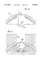
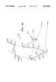
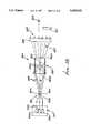
- FIG. 1is a vertical section in elevation showing one form of apparatus embodying a TIR lens
- FIG. 2is a vertical section in elevation showing another form of apparatus embodying a TIR lens
- FIG. 3is an enlarged section on lines 3--3 of FIG. 2;
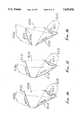
- FIGS. 4a-4eare enlarged sections through elements of various configurations
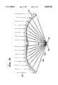
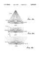
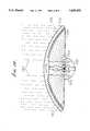
- FIG. 5is a view like FIG. 1 showing a portion of a solar optical concentrator of somewhat different and employed configuration
- FIG. 6is a schematic showing two devices, operating in conjunction, one of which is like that of FIG. 1 or 5, and the other being a collimator;
- FIG. 7is an enlarged section through a collimator as used in FIG. 6;
- FIGS. 8-11, 13, 14 and 15are schematics showing different applications of the radiant energy concentrating means
- FIGS. 12a and 12bare fragmentary sections showing modified concentrators
- FIGS. 16-18show various curved lens surface arrangements
- FIGS. 19a-19care sections producing light rays of varying angularity, as shown;
- FIG. 20is a section of a facet with three curved faces, illustrating the general principles of facet design
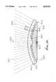
- FIG. 21is a section showing a further modified radiant energy concentrating means for use with a light-emitting diode
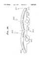
- FIG. 22is a section showing yet another modified radiant energy concentrating means made of silicon to pass infrared (IR) rays;
- FIG. 23is a section showing a radiant energy transmitting body means, as in FIG. 21a, directing converging light toward a light pipe;
- FIG. 24is a section showing a radiant energy transmitting means, directing diverging light as in a floodlight
- FIG. 25is a section showing a radiant energy transmitting means, directing light from a layer-stimulated sample to converge into a spectroscopic analyzer;
- FIG. 26is a section showing a radiant energy transmitting means, directing light from a toroidal source
- FIG. 27is a section like FIG. 25 but showing provision of a second lens, and a filter, in the path of collimated light or radiation;
- FIG. 28is a schematic view of a receiver, such as a TIR lens as referred to, in combination with LED dice and a light mixer cavity coupled between the dice and the receiver; and
- FIG. 29is a system block diagram.
- radiant energy transmitting body means 10in the shape of a cover or dome, has multiple facets or elements as at 11, each facet having an entry face to receive impingement of such radiation, an exit face to pass energy to the exterior of the body, and an internal reflection face angled relative to the entry and exit faces to reflect radiant energy incident on the reflection face toward the exit face.
- a selected facet 11has, in vertical cross section, an entry face 12 made up of stairstepped faces 12a and 12b, an exit face 13 facing the zone of target 15, and an internal reflection face 14.
- Radiant energysuch as light
- rays 16a and 16bentering the body means 10 at flat face 12a and normal thereto, and passing internally of the facet for reflection by face 14.
- face 14athe face may be silvered at 17.
- the reflected rays 16cthen pass toward and through exit face 13, normal thereto, and directly toward the target zone.
- the body means 10may consist of solid transparent material, such as glass or plastic, for example.
- the multiple facets 11 shown in FIG. 1may extend annularly about and define a common axis 18; or they may extend in parallel relation (normal to the plane of FIG. 1) at opposite sides of a plane as alternatively represented by 18, and which is normal to the plane of FIG. 1.
- corresponding points on the facetsdefine a concave surface, as for example at (defined by the tips 22 of the facets closest the target), and characterized in that radiant energy passing through the exit faces is directed generally toward the target zone. Tips 22 are formed at the intersections of the faces 13 and 14.
- Surface 21is parabolic.
- the series of facets in FIG. 1is further characterized by the existence of tapered gaps 23 between adjacent faces 24 and 14 of the projecting portions of the facets. Faces 24 are inactive surfaces, i.e., do not pass the radiation. See for example representative rays 25 and 26 in FIG. 1. Ray 25 is redirected by its associated facet almost 90° toward the target, near the outer edge 27 of the TIR lens 10. Study of FIGS. 1 and 4 will show that angle ⁇ (the bend angle of the ray) increases for facets increasing in distance from axis or plane 18; and that angle ⁇ (the angularity of face 14 relative to a line or plane parallel to line or plane 18) increases for facets increasing in distance from 18. Also, the entry faces 12 form stairstep patterns.
- FIG. 1further shows a Fresnel lens 29 associated with TIR lens or body 10, and located at a mid-portion of the latter; thus Fresnel lens 29, which refracts incident radiant energy toward target 15, is located in the path of rays 30, which are redirected the least, i.e., at the smallest angles, toward the target.
- Lens 29may be integral with lens 10, for example.
- a reflector or mirror surfaceis shown at 30 spaced from and facing the facets at the target side thereof.
- Surface 30is arranged to reflect stray or divergent radiation from the extreme outward facets toward the target. See ray 31 in this regard, and reflection point 31a. This allows target 15 to halve the area exposed to heat loss that it would have without surface 30, since the bottom non-illuminated half could be well insulated.
- FIG. 1Also shown in FIG. 1 is one form of means to controllably tilt the assembly of lenses 10 and 29 and reflector 30 to cause axis 18 to remain directed toward a relatively moving source of radiation, as for example the sun.
- a base plate 32supports reflector 30, as well as the dome-shaped lens 10 and 29, via extreme outer edge portion 10a of the body means 10.
- a ring gear 33supports plate 32, and meshes with spur gear 34.
- Drive motor 35rotates gear 34 to controllably rotate ring gear 33, and control unit 36 controls motor 35.
- Unit 36is responsive to photocells 37 and 38 in such manner that the photocells remain directed toward the light source.
- the photocellsare suitably carried at 99 by the plate 32, as for example near its periphery.
- Target 15may for example comprise a fluid receptacle which is heat conductive, to transmit heat to fluid in the receptacle, as for example water in a pipe.
- the numerals 100 and 129designate lenses corresponding to lenses 10 and 29 described above. They are elongated in the direction of arrow 149 and are carried by supports indicated at 150 and 151. V-shaped shroud 152 has edge portions 152a connected to the opposite edges of lens body 100, so that the shroud and lenses define an enclosure.
- a second and insulative tubular shroud 153extends within that enclosure, about a tank 154 which has fixed (nonrotatable) position.
- a support for the tankmay take the form of legs indicated at 155 and 156, bearings being provided at 157 and 158 to allow tank and shroud rotation about central axis 159, along with the lens assembly.
- the shroud 153is cut-away at locations 160 and 161 to allow entry of radiant energy from the lens assembly, to be absorbed by the tank, while heated air is prevented from escaping gap 162 by wipers 163; the enclosure has a reflecting interior surface 152b.
- Cool liquidsuch as water
- enters the tank via pipe 164is heated therein, and discharges into the tank lower end at 164a.
- Warmed liquidslowly flows at 200 back up the tank, being further heated by contact with the exterior of pipe 164, the liquid leaving the tank at outlet 165.
- a sacrificial anode 166 in the water 200is adapted to corrode, electrolytically suppressing any corrosion of the tank itself.
- a back-up heater 167 in water 200is supplied with electrical current to heat water in the tank as when solar radiation is blocked or non-existent, as at night.
- An air-gapmay be provided at 162 between shroud 153 and the tank itself.
- Sun tracking mechanismis indicated at 170, to rotate the assembly to maintain the sun's rays incident normally toward the lenses 100 and 129, i.e., in direction 171 in FIG. 3.
- TIR facecan be in faceted slots on either side of the body means or on the walls of tunnels within the latter, while the entry faces can be on faceted steps or even on a completely smooth cover surface.
- tunnel 40forms TIR face 41, while exit face 42 has stairsteps 42a and 42b.
- slot 50is on the entry side of the body means, having TIR face 51 and entry face 54.
- Exit face 52has stairsteps 52a and 52b.
- tunnel 60forms TIR face 61, and entry face 62 and exit face 64 are on smooth continuous surfaces.
- TIR face 61must be longer than TIR faces 41 of FIG. 4a or 51 of FIG. 4b, because of the refractive bending of ray 63 by entry face 62.
- the length of a TIR face relative to facet width 65is:
- TIR LENGTHcos ⁇ /(cos ⁇ cos ⁇ )
- ⁇is the incident angle of ray 63a with surface normal 66
- ⁇is the angle of the refracted ray 63b with 66
- ⁇is the incident angle of reflected ray 63c with exit surface normal 67
- ⁇the angle of refracted by 63d with 67.
- nis the index of refraction of the body means material.
- neighboring elementsmust be relatively positioned everywhere on or above a parabola with the target as its focus and a rim slope equal to half the rim angle (i.e., the redirective bend angle of the outermost elements).
- An alternative facet styleseeks to minimize such impingement losses by concentrating the rays before they strike the TIR face, which can thereby be smaller to reduce said impingement.
- Convex and concave entry and exit faceswill do this, though with some decrement of the cover's concentration ratio or acceptance angle, which for some applications is far outweighed by bringing the transparent redirecting means even closer to the target.
- FIG. 4eAnother method of widening the slots is the faceted exit face, shown in FIG. 4e.
- slot 70has been opened until it nearly impinges upon extreme ray 73b.
- Exit face 74has miniature stairsteps 74a and 74b, respectively normal to and parallel to reflected ray 73b.
- the particular manufacturing method and design applicationwill determine the place of transition to a Fresnel lens, or alternatively to a window, that passes rays to a small parabolic reflector below the target, which is thereby illuminated from a full circle of directions.
- Another possible configurationwould have the outer parts of the redirecting means sending radiant energy to a central target while the inner parts redirected energy to outer targets using only large bend angles throughout. All these configurations are derivatives of the basic method of this invention: upon multiple TIR-transmitting elements, properly placed entry, exit, and TIR faces redirect radiant energy to a predetermined target zone, or into a predetermined target solid angle.
- a cover means(as at 10 or 110) whose focal length can be shorter than any parabolic mirror with concentrations twice as high, but which is free from shading and presents a convex surface with lower aerodynamic drag than the concave parabolic mirror. Its target is near the center of gravity and closer to the ground than that of the parabolic reflector making fixed receiver means easier to design and maintain. Finally, the nearly 100% reflective efficiency of the TIR faces give much greater potential for high efficiencies than does the parabolic mirror.
- FIGS. 1 and 5it will be understood that the elements 11 and 311 join together, integrally and continuously, to form a radiant energy transmitting means in the general form of a cover.
- the latterhas an energy entry surface (top surface in FIG. 1, for example) and an exit surface (bottom surface in FIG. 1) lying on opposite sides of the cover.
- the covercauses radiant energy leaving the exit surface to have a generally different direction than the direction of energy incidence on the entry surface.
- multiple TIR facesare situated on the exit surface adjacent slots proximate the exit surface, as referred to above.
- the entry surfacehas a faceted stairstep configuration.
- the exit surface of the coverlies beyond and further from the target than a parabola (see 21 and 321).
- the covermay be constructed of transparent material, as for example plastic.
- FIG. 8schematically shows a means 410 corresponding to the means 10 of FIG. 1 or 310 of FIG. 5, or equivalent.
- a target zoneis shown at 415.
- a retroreflector means 412is spaced behind and facing the target zone so as to redirect radiant energy upon the target zone. See ray 413.
- FIG. 9schematically shows a radiant energy source means (as for example a light source) at 430 at the target zone. Radiant energy emitted by the source means 430 is redirected by the body means 435 (like 10 or 310) in reverse relation. See ray 436.
- a radiant energy source meansas for example a light source
- FIGS. 10a and 10bshow two variations of a "uni-bend" lens with uniform facets extending annularly about a cylindrical target.
- all the facets 444 of conical body means 440bend rays 443 through 90° onto cylindrical target 441.
- flat body means 445has identical facets 448 bending rays 447 through 45° upon cylindrical target 446.
- FIG. 11shows a structural means 460 enclosing the space 461 behind the exit face of the cover means 459 (like 10 or 310), so that pressurization of the atmosphere of space 461 will hold the flexible cover means in its distended or circular shape, with center of curvature at point 426. See target zone 462, pressurization means such as a pump 463 and ray 464.
- pressurization meanssuch as a pump 463 and ray 464.
- a thin film 465adheres to the inside of cover means 459, having miniature sawtooth facets 467 as shown in the insert.
- FIG. 12ashows a plurality (two for example) of target zones 470 and 471 to receive radiant energy from the transmitting body means 472 (like 10 or 310).
- Each element 473redirects energy in a plurality of directions, toward the target zones.
- each element 473may be like element 10 or 310 described above but have a TIR face divided into two sub-faces 474 and 475 at slightly different angles to accomplish the reflection of the two rays 476 and 477, respectively directed by the faces 474 and 475 toward the two target zones.
- TIR face 453is the exit face for ray 451; while TIR face 454 is the exit face for ray 452.
- This symmetrical case of twin 60° bendsmay be varied to give two different right and left hand bends, with differing division of the incoming radiant energy.
- the cover means 480(like 10 or 310) has different groups of elements redirecting radiant energy toward different target zones.
- the elements at locus 481direct radiant energy toward target 482; and the elements at locus 483 direct energy toward target 484. See rays 485 and 486.
- cover or body means 510corresponds to 10 or 310 described above.
- a secondary radiant energy redirecting meansis provided at 520 to intercept the radiant energy from body 510 and to redirect it. See rays 521 with segments 521a falling on body 510; redirected segments 521b falling on body 520; and secondarily redirected segments 521c transmitted by body 520.
- FIG. 7shows body 520 in detail, with entry faces 530, exit faces 531, and TIR faces 532.
- the rays 521care parallel, in this instance, i.e., collimated, so that means 520 may be regarded as a collimator.
- the means 550 shown in FIG. 14is like 10 and 300, except that the exit faces 551 are individually angled relative to radiant energy passing through them, so as to cause reflective redirection of the radiant energy. See beam 552 refracted at face 551. Also in FIG. 14, the exit faces 551 may be considered to refractively redirect radiant energy in partial opposition to the redirection by the TIR faces 553, the latter extending at less steep angles (than in FIGS. 1 and 5) so as to widen the slots 554. Note also in FIG.
- entry faceis smooth and unfaceted, at 556, and that exit face 551 is parallel to refracted ray 552b, giving the maximum backbend and the lowest possible slope of entry surface 556, which in fact is lower than the parabola 321 or the quarter-circle 325 in FIG. 5.
- the body means 560is like that at 10 or 310, except that it utilizes the variation index of refraction that varies with the wavelength of the radiant energy, so as to constitute a wavelength separating, radiating energy redirecting, transmitting body means.
- Two target zones 561 and 562are shown, and are spaced apart to receive different wavelengths of the wavelength separated, redirected, radiant energy. See incident ray 563 which separates into ray 563a of one wavelength directed toward target 561, and ray 563b of another wavelength directed toward target 562.
- either targetmay be considered as a means to convert radiant energy to electricity.
- One such meansis a photovoltaic cell.
- Such a devicemay be located at the target zones in FIGS. 1 and 5.
- one targetmay comprise a photoillumination means receiving visible wavelengths; and the other target may comprise a thermal receiver receiving invisible wavelengths at zone 561.
- the visible wavelength rayswill follow the reverse path of rays 563, i.e., be collimated, while the invisible longer wavelength heat rays will be diverged more outward from the visible beam, so that spotlights on actors will not subject them to a heat load several times greater than that of the visible radiation.
- FIGS. 1-15Certain aspects of FIGS. 1-15 were also discussed in prior patent 4,337,759.
- FIG. 16may be considered to correspond generally to FIG. 4a or FIG. 4b, i.e., to present a lens body 600 having an entry face 601, a TIR face 602, and an exit face 603 on the body 600.
- Such faces 601 and 603may be faceted, as in the styles shown in FIGS. 1, 3, 7, 8, 9, 10, and 13. Rather than all such faces being flat, face 601 is convexly curved, away from the body 600, as shown; whereas faces 602 and 603 are flat, as previously described.
- Diverging entry rays 605are refracted at 605a for reflection at 605b, and travel at 605c toward face 603. The rays pass through exit face 603 and are in general refracted to travel externally at 605d, as shown. If exit face 603 was convexly curved, then rays 605d could be converging.
- the curvature of entry face 601eliminates the divergence and keeps any rays from missing TIR face 602.
- entry face 611is flat, as is exit face 613; however, TIR face 612 is concave toward the incident ray side of that face, as shown.
- Diverging entry rays 615pass through face 611 and travel at 615a, within body 610, for reflection at 615b, at different points and angles, for travel at 615c toward face 613.
- the rayspass through that face, and are in general refracted, and travel externally at 615d, as shown.
- the curvature of the TIR face 612has made rays 615d parallel, while restricting the amount of exit face 613 that is used, enabling the entire lens to have a higher profile.
- entry face 621is flat, as is TIR face 622; however, exit face 623 is concave away from the body 620, i.e., away from TIR face 622, as shown.
- Entry rays 625which may be parallel, pass through face 621 and travel at 625a, within body 620, for reflection at 625b at different points and angles, for travel at 625c toward face 623. The rays then pass through that face and are in general refracted to travel externally at 625d, as shown. Exit face 623 is fully flashed, as would be desirable for a converging TIR lens.
- the bodies 650, 660 and 670are closely similar to body 740 shown and described in FIG. 21.
- the angularities of the annular facetsare slightly varied, so that the body 660 produces collimated light rays 664; body 650 produces converging light rays at 654; and a body 670 produces diverging light rays 674.
- the light source in each caseis shown at 680.
- the top surface 659, 669, and 679 of the lensis circularly curved in the section shown, or spherically curved for an annular lens.
- lens body 700acts as a converging TIR lens, in the same manner as lens 650 in FIG. 19a. Its performance is superior because of its full flashing, which gives more effective focusing, and higher profile, and which leads to smaller angular magnification of the light source, and a smaller focal spot.
- Upper light ray 701 and lower light ray 702are the defining rays for the calculation of the angles of the boundaries of facet 703 and of the position of inwardly adjacent facet 704. The slope of lens profile line 705 is to be maximized.
- the defining raysare generally diverging but can come from different parts of the light source; for example, upper ray 701 comes from the bottom of the light source, while lower ray 702 comes from the top of the light source, so that they constitute the extreme rays of all light emitted by the source.
- the facet-defining upper and lower raysare not the extreme rays of the light source, then some fraction of its output light will be redirected by the lens into the output rays. Such a case may occur if there is a tradeoff between this fraction and the tightness of the focusing, to be resolved by the particular application of the lens.
- Facet 703is defined by notch 703n (shown here as a fillet), tip 703t, upper point 703u of entry face 706, and on exit face 707, outer point 706o and inner point 706i.
- Inwardly adjacent facet 704provides three limiting points that act analogously to pupils of conventional optical systems: tip 704t defines upper ray 701, while both notch 704n and outer exit face 704o must be cleared by lower ray 702.
- the convex curvature of entry face 706accommodates the divergence of the defining rays by assuring that upper ray 701 does not miss TIR face 708 and that lower ray 702 does miss notch 704n.
- exit face 707is relatively close to TIR face 708.
- a thicker lens with a more distant exit facewould employ convex curvature (as on the TIR face 708c) to assure that the defining rays do not miss the edges of exit face 707. If they did miss, they would not be lost, since they would totally internally reflect on riser faces 709 or 710, and enter the lens output with only modest angular errors.
- Riser face 709is angled to just clear lower ray 702, after it has left the lens.
- Optically inactive face 711is kept at a minimum draft angle determined by the manufacturing method (for injection molds, it is typically 2° off the mold-pulling direction). Face 711 assists maximizing of lens profile by enabling entry face 706 to be angled more downward than is the case with lens 650 of FIG. 19a, where there is a straight line between a facet tip and the notch of the inwardly adjacent facet.
- a unique determination of the four angularities of the facetrequires four conditions: (1) overall bend angle; (2) upper ray falling on the TIR face; (3) lower ray clearing notch of the inwardly adjacent face; and (4) lower ray clearing the outer edge of exit facet of the inwardly adjacent facet.
- the curvatures of the three optically active faces of the facetare individually determined:
- entry-face curvaturehelps to maximize the slope of the lens profile line, by allowing the tip of the inwardly adjacent facet to rise while keeping the higher upper ray from missing the TIR face (this reduces the divergence of the output light of the inner facets of the lens by increasing their height above the source);
- TIR-face curvaturealso helps to maximize lens slope by allow the notch of the inwardly adjacent facet to rise; in addition, TIR-face curvature enables the exit face to be fully flashed, an important characteristic for several illumination applications;
- exit-face curvatureminimizes the size of the focal spot of converging TIR lenses, and minimizes the beam divergence of collimating TIR lenses.
- Non-circular profiles of these curved facesmay be selected in order to provide uniform illumination by the facet.
- the axis of the annular, radiant energy transmitting body 740appears at 751.
- the bodyhas multiple annular facets 742 to 746 which are generally concentrically arranged but having tips 742d to 746d progressively closer to plane 750 normal to axis 751.
- Face 742a of facet 742is convex toward face 742b; and face 742b is concave toward face 742a in the section shown. This relationship obtains for other facets, as shown.
- a light-emitting diode (LED) 758is located at the intersection of plane 750 with axis 751 and emits light rays toward the body 740.
- Ray 753passes through face 742a, is refracted toward TIR face 742b and is reflected toward and passes through upper flat face 748. See also ray 752 passing through face 743a, reflecting at TIR face 743b, and passing through upper face 748a, angled as shown. All rays passing upwardly beyond faces 748 and 748a are collimated.
- the transverse width of the body 740may be from 0.12 to one inch, for example, and the transparent body 740 may consist of molded plastic material.
- a refractive section without facetsappears at 719. Smaller ratios of lens diameter to LED size may have outermost facets large, and successively inward facets smaller, in order to have a higher lens profile and better collimation curved facets are necessary for.
- the radiant energy transmitting body 760may have the same general construction as shown in FIGS. 20 and 21.
- the lens body 760consists of silicon, or a similar material, for passing infrared rays, but blocking visible light rays, while transmitting infrared rays.
- An arc lamp radiant energy sourceis shown at 764, at the same position as the LED in FIG. 20.
- a reflector surface 765may be employed to extend in plane 766 corresponding to plane 750 in FIG. 21 with a parabolic section 762.
- the infrared rays emanating at 767are typically collimated but may be divergent or convergent, as in FIGS. 19a and 19c.
- unfaceted central section 770refracts rays, as shown.
- the arc light source at 764may be produced by anode and cathode elements 764a and 764b.
- Top exit surface 759is circularly curved in the section shown; but the lens may have external, stairstep faceting.
- Protective transparent envelope 769keeps outside air away from the arc.
- the body means 780may have the same or similar construction as that of FIG. 19a, for producing and directing convergent light at 781 into the entrance end 782 of a light pipe 783.
- the lenshas an upwardly convex arcuate upper exit surface or face 785, an entrance face or faces 786, and a TIR face or faces 787. Faces 786 and 787 taper downwardly toward plane 790, corresponding to plane 710 in FIG. 21.
- a central light source 788is positioned in the manner of the LED in FIG. 21.
- a planar back mirror 789extends in plane 790 corresponding to plane 710 and faces upwardly. This device may input up to 80% of the light into pipe 783, rather than 10% of the light as via a conventional ellipsoidal reflector.
- the body means 800may have the same or similar construction as that of FIG. 21c.
- Circularly curved top surface 801is curved downwardly.
- the lens axisin the case of an annular set of facets, is indicated at 802. Facets are seen from 803 to 812.
- a typical annular facet 809has an entrance face 809a and a TIR face 809b. Note ray 820 path passing through face 809a and face 801, and totally reflected at face 809b. In the section shown, each of the faces 809a and 809b is flat. All entry faces have draft in the direction 822, for ease of molding.
- the lensis transparent and may consist of molded plastic material.
- a light source 825is located on axis 802, and just above the plane 826, is within the confines of the hollow lens, as in the above examples; and the rays 827 emanating from face 802 diverge, as in a floodlight application.
- the circular section half-angle subtended by the surface 801is typically less than 45° and greater than 25° and is typically about 35°.
- lens body 850is the same as that of FIG. 21a, except that the central refractive means has been replaced by microscope objective 854, which can slide axially inside the lens to focus on sample 851.
- Characteristic diffuse (i.e., in all directions) emission 856 from sample 851is collected by lens 850 and focused on analyzer entrance slit 832.
- Collimated laser beam 855is reflected by mirror 853 into objective 854 and focused on sample 851.
- Mirror 853is removable in order to use microscope objective 854 to view sample 851 and exactly adjust its position.
- Lens body 850could extend downward below sample 851 to collect even more of the diffuse emission.
- Sample 851may be a glass capillary containing a gas or liquid, a gold hemisphere coated with a sample substance, an integrated circuit on a production line (checking material composition or contamination), or a biological tissue sample.
- lens body 860has a cross-section with axis 863, in order to accommodate toroidal (typically fluorescent) light source 861.
- Beneath this lampis annular involute reflector 862, with disc-shaped, planar mirror section 864 inside it and annulus mirror 865 outside it.
- Annular lens 866refracts ray 868, which was reflected from involute 862.
- Ray 869is exactly analogous to ray 820 in FIG. 24.
- Ray 867is redirected by facet 870.
- the overall device of lamp, lens, and reflectorcomprise a compact floodlamp that offers much narrower divergence and much higher efficiency than possible with the prior art of reflector design.
- the lens body 950is the same as shown in FIG. 19b or as in FIG. 25, modified to collimate light or a laser beam, supplied as indicated at 955.
- a light source or light-emitting target (laser for example) 951transmits light to faceted side of the TIR lens body 950, the latter redirecting the light rays, as shown by the broken lines 956 and 980, to pass through first refracting lens means at surface 950a and emerge as collimated light at 955.
- Such lightthen impinges on and passes through the wavelength selective filter 982 and then through a second lens means 983 indicated in the example as a focusing Fresnel lens.
- the latterredirects or focuses light at 984 onto the sample, or an analyser, 952.
- a wavelength-selective filter 982is used to remove passively scattered light of the collimated laser beam 955, while allowing passage of fluorescence wavelengths, such as those generated in Raman spectroscopy, for stimulated emissions at 952.
- the filter 982extends in a plane normal to principal axis 986 defined by the lens 950 and by lens 983, the filter requiring normal incidence of light for good wavelength selection, since the filter wavelength depends upon the angle of incidence.
- the filtertypically removes the laser wavelengths.
- the auxiliary or second lens means 983can also act to reduce any aberrations introduced by the annular TIR lens 950.
- a microscope objective lens 954which can slide axially in a bore in lens 950, and focus auxiliary source light 965 onto the target or laser 951.
- a means to adjustably move objective lens 954 axiallyis schematically shown at 968.
- Auxiliary source light 965may be redirected by mirror 953, as shown, toward lens 954, for focusing onto the target 951.
- the apparatus 900 shownis a multiple wavelength illuminator. It includes at least two light-emitting sources, each emitting different frequency light. Such sources are indicated at 901. Three sources 901a, 901b, and 901c are shown, for emitting red, green and blue light; and they may advantageously comprise LED (light-emitting diode) dice, clustered, as shown.
- LEDlight-emitting diode
- a light receiveris generally indicated at 902, and may comprise a TIR lens of the type described above.
- the receiveris positioned to receive light originating at the sources 901, for illumination of the receiver.
- the light transmitted by the receivermay be collimated, as indicated by rays 903. Viewing of rays is indicated at 904.
- the cavityreceives light rays 906 from the sources 901, and effects mixing of such rays, in order to act as a secondary light emitter. Mixed light output from 905 is transmitted at 907 to illuminate the receiver.
- the cavity 905typically has light reflective wall means, indicated at 905a, and which is diffusively reflective.
- the cavitymay be generally tubular to have an entrance end 905b for rays 906, and an exit end 905c, for transmitting light 907, that comprises a mixture of rays 906.
- Wall means 905aeffects reflection and re-reflection of received rays 906 within the optical cavity, and toward the exit end 905c.
- Wall means 905amay be annular about axis 908.
- the secondary emitteracts as a uniform source for a lens or reflector, which is the output means of the radiation of the far-field. It is a further object of this invention that the secondary emitter 905 have a shape, so as to give the output lens or reflector element 902 a nearly uniform output light flux pattern over the output plane, and thus to compensate for the 1/R 2 radiation falloff that is normally observed.
- the walls of the optical cavitywill normally be constructed of highly reflective material, with reflectivities typically greater than 95%. Further, the walls will usually be fabricated from highly diffusely reflective material, as opposed to specularly reflecting material. It is possible to construct the walls from specularly reflecting materials (such as reflective aluminum) provided that the walls of this material have a number of scattering centers or bumps built into such walls, so as to randomize the directions of the reflected radiation, and thus essentially reproducing the effect of the diffusely reflecting surface.
- specularly reflecting materialssuch as reflective aluminum
- the optimal shape of the secondary emitter 905may be accomplished using geometry, as in surface area presented to the output optical device 902 per unit solid angle, or it may be accomplished by using non-uniform holographic diffusers or specially designed refractive element(s) at the surface of the secondary emitter, or in close proximity to the secondary emitter.
- the tri-color LED illuminator 901may have the red, green and blue dice driven all at once and with appropriate drive currents to each dice, such that white light is produced at 906 or any other color of the spectrum, by simple adjustments to the drive currents of the individual LED dice.
- each LEDin sequence (e.g., red, then green, then blue), such that the unit 905 becomes a sequential backlight for a monochrome LCD, and thus allows for an increase by a factor of three the image resolution of the LCD display when compared to full color active matrix displays of the same pixel size.
- Such an LCD displayis indicated at 911, in the path of rays 903.
- a planar mirror 915is located just rearwardly of the secondary emitter 905, for reflecting light forwardly toward the receiver 902 shown in the form of a collimating TIR lens.
- a light ray integrating (mixing) cavityis shown at 905.
Landscapes
- Physics & Mathematics (AREA)
- General Physics & Mathematics (AREA)
- Optics & Photonics (AREA)
- Engineering & Computer Science (AREA)
- General Engineering & Computer Science (AREA)
- Sustainable Development (AREA)
- Life Sciences & Earth Sciences (AREA)
- Sustainable Energy (AREA)
- Thermal Sciences (AREA)
- Chemical & Material Sciences (AREA)
- Combustion & Propulsion (AREA)
- Mechanical Engineering (AREA)
- Health & Medical Sciences (AREA)
- Toxicology (AREA)
- Lenses (AREA)
Abstract
Description
______________________________________ flat convex concave ______________________________________ A x entry face exit face x TIR face x entry face x exit face x TIR face x C entry face x exit face x TIR face x ______________________________________
Claims (29)
Priority Applications (1)
| Application Number | Priority Date | Filing Date | Title |
|---|---|---|---|
| US08/445,892US5655832A (en) | 1992-04-16 | 1995-05-22 | Multiple wavelength light processor |
Applications Claiming Priority (3)
| Application Number | Priority Date | Filing Date | Title |
|---|---|---|---|
| US07/869,003US5404869A (en) | 1992-04-16 | 1992-04-16 | Faceted totally internally reflecting lens with individually curved faces on facets |
| US08/415,274US5577492A (en) | 1992-04-16 | 1995-04-07 | Collimating TIR lens with focusing filter lens |
| US08/445,892US5655832A (en) | 1992-04-16 | 1995-05-22 | Multiple wavelength light processor |
Related Parent Applications (1)
| Application Number | Title | Priority Date | Filing Date |
|---|---|---|---|
| US08/415,274Continuation-In-PartUS5577492A (en) | 1992-04-16 | 1995-04-07 | Collimating TIR lens with focusing filter lens |
Publications (1)
| Publication Number | Publication Date |
|---|---|
| US5655832Atrue US5655832A (en) | 1997-08-12 |
Family
ID=46202637
Family Applications (1)
| Application Number | Title | Priority Date | Filing Date |
|---|---|---|---|
| US08/445,892Expired - LifetimeUS5655832A (en) | 1992-04-16 | 1995-05-22 | Multiple wavelength light processor |
Country Status (1)
| Country | Link |
|---|---|
| US (1) | US5655832A (en) |
Cited By (141)
| Publication number | Priority date | Publication date | Assignee | Title |
|---|---|---|---|---|
| WO1999014528A1 (en) | 1997-09-18 | 1999-03-25 | Everbrite, Inc. | Lighting fixture with collimating lens |
| US5892325A (en)* | 1993-10-05 | 1999-04-06 | Teledyne Lighting And Display Products, Inc. | Backlighting apparatus for uniformly illuminating a display panel |
| WO1999024951A1 (en)* | 1997-11-12 | 1999-05-20 | Control Devices, Inc. | Solar radiation sensor |
| US6007209A (en)* | 1997-03-19 | 1999-12-28 | Teledyne Industries, Inc. | Light source for backlighting |
| US6043591A (en)* | 1993-10-05 | 2000-03-28 | Teledyne Lighting And Display Products, Inc. | Light source utilizing diffusive reflective cavity |
| US6102552A (en)* | 1996-10-18 | 2000-08-15 | Hewlett-Packard Company | Laser-array based digital illuminator |
| US6134092A (en)* | 1998-04-08 | 2000-10-17 | Teledyne Lighting And Display Products, Inc. | Illumination device for non-emissive displays |
| US6238076B1 (en) | 1999-03-29 | 2001-05-29 | Primetech Electronics, Inc. | Compact light mixing and diffusing apparatus |
| US6243002B1 (en) | 1997-11-17 | 2001-06-05 | Control Devices | Tunnel sensor |
| US6304355B1 (en)* | 1995-12-29 | 2001-10-16 | Warren M. Farnworth | Modulation and demodulation of light to facilitate transmission of information |
| US6313892B2 (en) | 1993-10-05 | 2001-11-06 | Teledyne Lighting And Display Products, Inc. | Light source utilizing reflective cavity having sloped side surfaces |
| US6368159B1 (en)* | 2000-12-13 | 2002-04-09 | Stewart Connector Systems, Inc. | Light pipe for a modular jack |
| EP1198960A1 (en) | 1999-06-25 | 2002-04-24 | Sarnoff Corporation | Color display |
| US6424321B1 (en) | 1993-10-22 | 2002-07-23 | Kopin Corporation | Head-mounted matrix display |
| US6473554B1 (en) | 1996-12-12 | 2002-10-29 | Teledyne Lighting And Display Products, Inc. | Lighting apparatus having low profile |
| US20020198576A1 (en)* | 1999-01-15 | 2002-12-26 | James Chen | Patient portable device for photodynamic therapy |
| US6545654B2 (en) | 1996-10-31 | 2003-04-08 | Kopin Corporation | Microdisplay for portable communication systems |
| US20030109813A1 (en)* | 1999-01-15 | 2003-06-12 | James Chen | Energy-activated targeted cancer therapy |
| US6580053B1 (en)* | 2000-08-31 | 2003-06-17 | Sharp Laboratories Of America, Inc. | Apparatus to control the amount of oxygen incorporated into polycrystalline silicon film during excimer laser processing of silicon films |
| US6597709B1 (en)* | 2000-10-05 | 2003-07-22 | The United States Of America As Represented By The United States Department Of Energy | Method and apparatus for aligning a solar concentrator using two lasers |
| US20030189290A1 (en)* | 2002-01-22 | 2003-10-09 | Moody Ernest W. | Video poker games |
| US6683584B2 (en) | 1993-10-22 | 2004-01-27 | Kopin Corporation | Camera display system |
| EP1243844A3 (en)* | 2001-03-23 | 2004-03-17 | Stanley Electric Co., Ltd. | Projector type lamp |
| US20040057234A1 (en)* | 2002-09-19 | 2004-03-25 | Ferenc Mohacsi | High-intensity directional light |
| US20040070855A1 (en)* | 2002-10-11 | 2004-04-15 | Light Prescriptions Innovators, Llc, A Delaware Limited Liability Company | Compact folded-optics illumination lens |
| US20040105171A1 (en)* | 2002-12-02 | 2004-06-03 | Light Prescriptions Innovators, Llc, A Delaware Limited Liability Company | Asymmetric TIR lenses producing off-axis beams |
| US20040165381A1 (en)* | 2003-02-25 | 2004-08-26 | Ryan Waters | LED light apparatus and methodology |
| US20040189933A1 (en)* | 2002-12-02 | 2004-09-30 | Light Prescription Innovators, Llc | Apparatus and method for use in fulfilling illumination prescription |
| US20040217258A1 (en)* | 2003-04-30 | 2004-11-04 | Clugston P. Edward | Solar sensor including reflective element to transform the angular response |
| US20040228131A1 (en)* | 2003-05-13 | 2004-11-18 | Light Prescriptions Innovators, Llc, A Delaware Limited Liability Company | Optical device for LED-based light-bulb substitute |
| US20050024744A1 (en)* | 2003-07-29 | 2005-02-03 | Light Prescriptions Innovators, Llc | Circumferentially emitting luminaires and lens-elements formed by transverse-axis profile-sweeps |
| US20050086032A1 (en)* | 2003-07-28 | 2005-04-21 | Light Prescriptions Innovators, Llc | Three-dimensional simultaneous multiple-surface method and free-form illumination-optics designed therefrom |
| US20050129358A1 (en)* | 2003-02-04 | 2005-06-16 | Light Prescriptions Innovators, Llc A Delaware Limited Liability Company | Etendue-squeezing illumination optics |
| US20050225988A1 (en)* | 2003-05-13 | 2005-10-13 | Light Prescriptions Innovators, Llc | Optical device for LED-based lamp |
| US20050244468A1 (en)* | 2004-04-30 | 2005-11-03 | Allergan, Inc. | Sustained release intraocular implants and related methods |
| US20050244465A1 (en)* | 2004-04-30 | 2005-11-03 | Allergan, Inc. | Drug delivery systems and methods for treatment of an eye |
| US20050244464A1 (en)* | 2004-04-30 | 2005-11-03 | Allergan, Inc. | Hypotensive lipid-containing biodegradable intraocular implants and related methods |
| US20050244461A1 (en)* | 2004-04-30 | 2005-11-03 | Allergan, Inc. | Controlled release drug delivery systems and methods for treatment of an eye |
| US20050244500A1 (en)* | 2004-04-30 | 2005-11-03 | Allergan, Inc. | Intravitreal implants in conjuction with photodynamic therapy to improve vision |
| US20050244462A1 (en)* | 2004-04-30 | 2005-11-03 | Allergan, Inc. | Devices and methods for treating a mammalian eye |
| US20050244463A1 (en)* | 2004-04-30 | 2005-11-03 | Allergan, Inc. | Sustained release intraocular implants and methods for treating ocular vasculopathies |
| US20050244478A1 (en)* | 2004-04-30 | 2005-11-03 | Allergan, Inc. | Anti-excititoxic sustained release intraocular implants and related methods |
| US20050244479A1 (en)* | 2004-04-30 | 2005-11-03 | Allergan, Inc. | Sustained release intraocular implants and methods for preventing retinal dysfunction |
| US20050244471A1 (en)* | 2004-04-30 | 2005-11-03 | Allergan, Inc. | Estradiol derivative and estratopone containing sustained release intraocular implants and related methods |
| US20050244470A1 (en)* | 2004-04-30 | 2005-11-03 | Allergan, Inc. | Sustained release intraocular implants containing tyrosine kinase inhibitors and related methods |
| US20050244466A1 (en)* | 2004-04-30 | 2005-11-03 | Allergan, Inc. | Photodynamic therapy in conjunction with intraocular implants |
| US6969180B2 (en) | 2003-02-25 | 2005-11-29 | Ryan Waters | LED light apparatus and methodology |
| US20050281861A1 (en)* | 2004-04-30 | 2005-12-22 | Allergan, Inc. | Macromolecule-containing sustained release intraocular implants and related methods |
| US20060262514A1 (en)* | 2005-05-19 | 2006-11-23 | Conner Arlie R | Polarized, LED-based illumination source |
| US20070008711A1 (en)* | 2005-07-11 | 2007-01-11 | Mox Tronix Co., Ltd. | Multifunction lighting and audio system |
| US20070059336A1 (en)* | 2004-04-30 | 2007-03-15 | Allergan, Inc. | Anti-angiogenic sustained release intraocular implants and related methods |
| US7271945B2 (en) | 2005-02-23 | 2007-09-18 | Pixtronix, Inc. | Methods and apparatus for actuating displays |
| US20070224246A1 (en)* | 2004-04-30 | 2007-09-27 | Hughes Patrick M | Oil-in-oil emulsified polymeric implants containing a hypotensive lipid and related methods |
| US7304785B2 (en) | 2005-02-23 | 2007-12-04 | Pixtronix, Inc. | Display methods and apparatus |
| US7304786B2 (en) | 2005-02-23 | 2007-12-04 | Pixtronix, Inc. | Methods and apparatus for bi-stable actuation of displays |
| US20080062686A1 (en)* | 2004-09-24 | 2008-03-13 | Koninklijke Philips Electronics, N.V. | Illumination System |
| US7365897B2 (en) | 2005-02-23 | 2008-04-29 | Pixtronix, Inc. | Methods and apparatus for spatial light modulation |
| US20080165437A1 (en)* | 2007-01-10 | 2008-07-10 | Xtreme Energetics Inc. | Non-imaging facet based optics |
| US7405852B2 (en) | 2005-02-23 | 2008-07-29 | Pixtronix, Inc. | Display apparatus and methods for manufacture thereof |
| US20080201665A1 (en)* | 2007-02-15 | 2008-08-21 | Teac Corporation | Electronic equipment having plural function keys |
| US20080258291A1 (en)* | 2007-04-19 | 2008-10-23 | Chenglin Liu | Semiconductor Packaging With Internal Wiring Bus |
| US7502159B2 (en) | 2005-02-23 | 2009-03-10 | Pixtronix, Inc. | Methods and apparatus for actuating displays |
| US20090071467A1 (en)* | 2005-07-28 | 2009-03-19 | Light Prescriptions Innovators, Llc | Multi-junction solar cells with a homogenizer system and coupled non-imaging light concentrator |
| US7511031B2 (en) | 1999-01-15 | 2009-03-31 | Lights Sciences Oncology, Inc. | Noninvasive vascular therapy |
| WO2009055810A1 (en)* | 2007-10-25 | 2009-04-30 | U.S. Environmental Agency | Microorganism discriminator and method |
| US7559672B1 (en) | 2007-06-01 | 2009-07-14 | Inteled Corporation | Linear illumination lens with Fresnel facets |
| US20090180276A1 (en)* | 2006-07-14 | 2009-07-16 | Light Prescriptions Innovators, Llc | Brightness-enhancing film |
| US20090185107A1 (en)* | 2008-01-18 | 2009-07-23 | Panagotacos George W | Low profile backlight apparatus |
| US20090225529A1 (en)* | 2008-02-21 | 2009-09-10 | Light Prescriptions Innovators, Llc | Spherically emitting remote phosphor |
| US7616368B2 (en) | 2005-02-23 | 2009-11-10 | Pixtronix, Inc. | Light concentrating reflective display methods and apparatus |
| US20100033974A1 (en)* | 2006-10-20 | 2010-02-11 | Henning Rehn | Lamp module for projectors |
| US20100033946A1 (en)* | 2006-08-11 | 2010-02-11 | Light Prescriptions Innovators, Llc | Led luminance-enhancement and color-mixing by rotationally multiplexed beam-combining |
| US20100038663A1 (en)* | 2006-08-10 | 2010-02-18 | Light Prescriptions Innovators, Llc | Led light recycling for luminance enhancement and angular narrowing |
| US7675665B2 (en) | 2005-02-23 | 2010-03-09 | Pixtronix, Incorporated | Methods and apparatus for actuating displays |
| US7742016B2 (en) | 2005-02-23 | 2010-06-22 | Pixtronix, Incorporated | Display methods and apparatus |
| US7746529B2 (en) | 2005-02-23 | 2010-06-29 | Pixtronix, Inc. | MEMS display apparatus |
| US7755582B2 (en) | 2005-02-23 | 2010-07-13 | Pixtronix, Incorporated | Display methods and apparatus |
| USRE41685E1 (en)* | 1999-12-28 | 2010-09-14 | Honeywell International, Inc. | Light source with non-white and phosphor-based white LED devices, and LCD assembly |
| US20100238680A1 (en)* | 2007-10-25 | 2010-09-23 | Stuart Martin A | Laser energy source device and method |
| US7839356B2 (en) | 2005-02-23 | 2010-11-23 | Pixtronix, Incorporated | Display methods and apparatus |
| US7852546B2 (en) | 2007-10-19 | 2010-12-14 | Pixtronix, Inc. | Spacers for maintaining display apparatus alignment |
| US7876489B2 (en) | 2006-06-05 | 2011-01-25 | Pixtronix, Inc. | Display apparatus with optical cavities |
| US20110034448A1 (en)* | 2004-04-30 | 2011-02-10 | Allergan, Inc. | Carbonic anhydrase inhibitor sustained release intraocular drug delivery systems |
| US20110043120A1 (en)* | 2009-08-21 | 2011-02-24 | Panagotacos George W | Lamp assembly |
| US20110091520A1 (en)* | 2004-04-30 | 2011-04-21 | Allergan, Inc. | Sustained Release Intraocular Implants and Methods for Treating Ocular Neuropathies |
| US8075147B2 (en) | 2003-05-13 | 2011-12-13 | Light Prescriptions Innovators, Llc | Optical device for LED-based lamp |
| WO2012037035A1 (en) | 2010-09-13 | 2012-03-22 | Teledyne Lighting And Display Products, Inc. | Collimating waveguide apparatus and method |
| US8147865B2 (en) | 2004-04-30 | 2012-04-03 | Allergan, Inc. | Steroid-containing sustained release intraocular implants and related methods |
| US8159428B2 (en) | 2005-02-23 | 2012-04-17 | Pixtronix, Inc. | Display methods and apparatus |
| US8238050B2 (en) | 2008-06-13 | 2012-08-07 | Light Prescriptions Innovators, Llc | Reflectors made of linear grooves |
| US8248560B2 (en) | 2008-04-18 | 2012-08-21 | Pixtronix, Inc. | Light guides and backlight systems incorporating prismatic structures and light redirectors |
| US8262274B2 (en) | 2006-10-20 | 2012-09-11 | Pitronix, Inc. | Light guides and backlight systems incorporating light redirectors at varying densities |
| US20120262782A1 (en)* | 2011-04-15 | 2012-10-18 | Lee Jeffrey B | Multiple Wavelength LED Array Illuminator for Fluorescence Microscopy |
| US8310442B2 (en) | 2005-02-23 | 2012-11-13 | Pixtronix, Inc. | Circuits for controlling display apparatus |
| US8393777B2 (en) | 2005-07-28 | 2013-03-12 | Light Prescriptions Innovators, Llc | Etendue-conserving illumination-optics for backlights and frontlights |
| US8419232B2 (en) | 2005-07-28 | 2013-04-16 | Light Prescriptions Innovators, Llc | Free-form lenticular optical elements and their application to condensers and headlamps |
| US8455656B2 (en) | 2004-04-30 | 2013-06-04 | Allergan, Inc. | Kinase inhibitors |
| US8482496B2 (en) | 2006-01-06 | 2013-07-09 | Pixtronix, Inc. | Circuits for controlling MEMS display apparatus on a transparent substrate |
| US20130182452A1 (en)* | 2012-01-18 | 2013-07-18 | Sharp Kabushiki Kaisha | Light-emitting device, illumination device, and vehicle headlamp |
| US20130194645A1 (en)* | 2006-10-20 | 2013-08-01 | Carl Raymond Amos | Advanced Methods of and Apparatus for the Manipulation of Electromagnetic Phenomenon: the Decoding of Genetic Material and the Human Genome (E3) |
| US8512738B2 (en) | 2004-04-30 | 2013-08-20 | Allergan, Inc. | Biodegradable intravitreal tyrosine kinase implants |
| US8519945B2 (en) | 2006-01-06 | 2013-08-27 | Pixtronix, Inc. | Circuits for controlling display apparatus |
| US8520285B2 (en) | 2008-08-04 | 2013-08-27 | Pixtronix, Inc. | Methods for manufacturing cold seal fluid-filled display apparatus |
| US8526096B2 (en) | 2006-02-23 | 2013-09-03 | Pixtronix, Inc. | Mechanical light modulators with stressed beams |
| US8599463B2 (en) | 2008-10-27 | 2013-12-03 | Pixtronix, Inc. | MEMS anchors |
| WO2014020475A1 (en)* | 2012-07-30 | 2014-02-06 | Koninklijke Philips N.V. | Fresnel type lens for lighting applications |
| US8673341B2 (en) | 2004-04-30 | 2014-03-18 | Allergan, Inc. | Intraocular pressure reduction with intracameral bimatoprost implants |
| US8846094B2 (en) | 2003-11-12 | 2014-09-30 | Allergan, Inc. | Peripherally administered viscous formulations |
| US8950900B2 (en) | 2007-10-25 | 2015-02-10 | Martin A. Stuart | Laser energy source device |
| US8969415B2 (en) | 2006-12-01 | 2015-03-03 | Allergan, Inc. | Intraocular drug delivery systems |
| US9082353B2 (en) | 2010-01-05 | 2015-07-14 | Pixtronix, Inc. | Circuits for controlling display apparatus |
| US9087486B2 (en) | 2005-02-23 | 2015-07-21 | Pixtronix, Inc. | Circuits for controlling display apparatus |
| US20150219308A1 (en)* | 2012-08-23 | 2015-08-06 | Koninklijke Philips N.V. | Lighting device with a LED and an improved reflective collimator |
| US9101583B2 (en) | 2004-04-30 | 2015-08-11 | Allergan, Inc. | Microparticles manufactured in an oil-in-water process comprising a prostamide |
| US9134552B2 (en) | 2013-03-13 | 2015-09-15 | Pixtronix, Inc. | Display apparatus with narrow gap electrostatic actuators |
| US9135868B2 (en) | 2005-02-23 | 2015-09-15 | Pixtronix, Inc. | Direct-view MEMS display devices and methods for generating images thereon |
| US9138480B2 (en) | 2009-11-09 | 2015-09-22 | Allergan, Inc. | Compositions and methods for stimulating hair growth |
| US9176318B2 (en) | 2007-05-18 | 2015-11-03 | Pixtronix, Inc. | Methods for manufacturing fluid-filled MEMS displays |
| US9229222B2 (en) | 2005-02-23 | 2016-01-05 | Pixtronix, Inc. | Alignment methods in fluid-filled MEMS displays |
| US9261694B2 (en) | 2005-02-23 | 2016-02-16 | Pixtronix, Inc. | Display apparatus and methods for manufacture thereof |
| US9265775B2 (en) | 2003-11-12 | 2016-02-23 | Allergan, Inc. | Pharmaceutical compositions |
| US20160169473A1 (en)* | 2014-12-12 | 2016-06-16 | The Boeing Company | Diffuser techniques for searchlights |
| US20160258593A1 (en)* | 2015-03-03 | 2016-09-08 | Ecosense Lighting Inc. | Lighting systems including asymmetric lens modules for selectable light distribution |
| US9470895B2 (en) | 2013-06-18 | 2016-10-18 | Sharp Kabushiki Kaisha | Light-emitting device |
| US9500853B2 (en) | 2005-02-23 | 2016-11-22 | Snaptrack, Inc. | MEMS-based display apparatus |
| US9565782B2 (en) | 2013-02-15 | 2017-02-07 | Ecosense Lighting Inc. | Field replaceable power supply cartridge |
| US9568665B2 (en)* | 2015-03-03 | 2017-02-14 | Ecosense Lighting Inc. | Lighting systems including lens modules for selectable light distribution |
| US9572859B2 (en) | 2004-01-20 | 2017-02-21 | Allergan, Inc. | Compositions and methods for localized therapy of the eye |
| US9610246B2 (en) | 2013-02-15 | 2017-04-04 | Allergan, Inc. | Sustained drug delivery implant |
| USD785218S1 (en) | 2015-07-06 | 2017-04-25 | Ecosense Lighting Inc. | LED luminaire having a mounting system |
| US9651227B2 (en) | 2015-03-03 | 2017-05-16 | Ecosense Lighting Inc. | Low-profile lighting system having pivotable lighting enclosure |
| US9651232B1 (en) | 2015-08-03 | 2017-05-16 | Ecosense Lighting Inc. | Lighting system having a mounting device |
| US9746159B1 (en) | 2015-03-03 | 2017-08-29 | Ecosense Lighting Inc. | Lighting system having a sealing system |
| US9775846B2 (en) | 2004-04-30 | 2017-10-03 | Allergan, Inc. | Hypotensive lipid-containing biodegradable intraocular implants and related implants |
| US9869450B2 (en) | 2015-02-09 | 2018-01-16 | Ecosense Lighting Inc. | Lighting systems having a truncated parabolic- or hyperbolic-conical light reflector, or a total internal reflection lens; and having another light reflector |
| US20180177386A1 (en)* | 2015-06-19 | 2018-06-28 | Koninklijke Philips N.V. | Imaging system, optical element, and a catheter or endoscope using the same |
| US20190113190A1 (en)* | 2015-09-25 | 2019-04-18 | Hubbell Incorporated | Luminaire |
| US10422998B1 (en) | 2015-06-03 | 2019-09-24 | Mark Belloni | Laser transformer lens |
| US10801696B2 (en) | 2015-02-09 | 2020-10-13 | Ecosense Lighting Inc. | Lighting systems generating partially-collimated light emissions |
| US11306897B2 (en) | 2015-02-09 | 2022-04-19 | Ecosense Lighting Inc. | Lighting systems generating partially-collimated light emissions |
| US11892652B1 (en) | 2020-04-07 | 2024-02-06 | Mark Belloni | Lenses for 2D planar and curved 3D laser sheets |
Citations (30)
| Publication number | Priority date | Publication date | Assignee | Title |
|---|---|---|---|---|
| US1421506A (en)* | 1922-07-04 | Headlight | ||
| GB1325086A (en)* | 1971-05-21 | 1973-08-01 | Dorman Smith Traffic Products | Lamp |
| GB1325087A (en)* | 1971-05-21 | 1973-08-01 | Dorman Smith Traffic Products | Lamp |
| US3915148A (en)* | 1974-11-22 | 1975-10-28 | Nasa | Thermostatically controlled non-tracking type solar energy concentrator |
| US3941993A (en)* | 1973-10-12 | 1976-03-02 | C G R Alexandre | Illuminating device in particular for an operating table |
| US3970070A (en)* | 1975-09-03 | 1976-07-20 | Meyer Stanley A | Solar heating system |
| US4002031A (en)* | 1975-07-07 | 1977-01-11 | Varian Associates, Inc. | Solar energy converter with waste heat engine |
| US4022186A (en)* | 1975-09-10 | 1977-05-10 | Northrup Jr Leonard L | Compound lens solar energy system |
| US4074704A (en)* | 1976-05-28 | 1978-02-21 | Gellert Donald P | Process of and apparatus for solar heating and the like |
| US4103673A (en)* | 1976-12-06 | 1978-08-01 | Woodworth Robert N | Non-tracking solar energy concentrator |
| US4108540A (en)* | 1976-06-17 | 1978-08-22 | Minnesota Mining And Manufacturing Company | Refractor-reflector radiation concentrator |
| US4116223A (en)* | 1977-01-18 | 1978-09-26 | Michael Vasilantone | Solar energy unit |
| US4124017A (en)* | 1977-06-17 | 1978-11-07 | James B. Paull & Co., Inc. | Collimating solar radiation collector |
| US4136670A (en)* | 1977-06-13 | 1979-01-30 | Davis Theodore L | Solar heating collector apparatus |
| GB1546791A (en)* | 1976-07-26 | 1979-05-31 | Dorman Smith Traffic Products | Lamps |
| GB1546793A (en)* | 1976-07-26 | 1979-05-31 | Dorman Smith Traffic Products | Switch assembly |
| GB1546792A (en)* | 1976-07-26 | 1979-05-31 | Dorman Smith Traffic Products | Battery-powered lamps |
| US4171695A (en)* | 1977-10-03 | 1979-10-23 | Solar Energy Technology, Inc. | Image collapsing concentrator and method for collecting and utilizing solar energy |
| GB1557472A (en)* | 1977-05-06 | 1979-12-12 | Dorman Smith Traffic Products | Electric lamps |
| GB1561129A (en)* | 1977-05-03 | 1980-02-13 | Dorman Smith Traffic Products | Battery-powered lamps |
| US4194949A (en)* | 1977-06-15 | 1980-03-25 | Virgil Stark | Solar distillation apparatus |
| US4337759A (en)* | 1979-10-10 | 1982-07-06 | John M. Popovich | Radiant energy concentration by optical total internal reflection |
| US4755921A (en)* | 1986-04-02 | 1988-07-05 | Minnesota Mining And Manufacturing Company | Lens |
| US4767172A (en)* | 1983-01-28 | 1988-08-30 | Xerox Corporation | Collector for an LED array |
| GB2239940A (en)* | 1990-01-11 | 1991-07-17 | Dorman Traffic Prod | Warning lamps |
| US5070431A (en)* | 1989-08-03 | 1991-12-03 | Pioneer Electronic Corporation | Display board illuminating device for passive displays |
| US5150966A (en)* | 1990-09-19 | 1992-09-29 | Minnesota Mining And Manufacturing Company | Uniform intensity profile catadioptric lens |
| US5187377A (en)* | 1988-07-15 | 1993-02-16 | Sharp Kabushiki Kaisha | LED array for emitting light of multiple wavelengths |
| US5404869A (en)* | 1992-04-16 | 1995-04-11 | Tir Technologies, Inc. | Faceted totally internally reflecting lens with individually curved faces on facets |
| US5504514A (en)* | 1992-02-13 | 1996-04-02 | Texas Instruments Incorporated | System and method for solid state illumination for spatial light modulators |
- 1995
- 1995-05-22USUS08/445,892patent/US5655832A/ennot_activeExpired - Lifetime
Patent Citations (31)
| Publication number | Priority date | Publication date | Assignee | Title |
|---|---|---|---|---|
| US1421506A (en)* | 1922-07-04 | Headlight | ||
| GB1325086A (en)* | 1971-05-21 | 1973-08-01 | Dorman Smith Traffic Products | Lamp |
| GB1325087A (en)* | 1971-05-21 | 1973-08-01 | Dorman Smith Traffic Products | Lamp |
| US3941993A (en)* | 1973-10-12 | 1976-03-02 | C G R Alexandre | Illuminating device in particular for an operating table |
| US3915148A (en)* | 1974-11-22 | 1975-10-28 | Nasa | Thermostatically controlled non-tracking type solar energy concentrator |
| US4002031A (en)* | 1975-07-07 | 1977-01-11 | Varian Associates, Inc. | Solar energy converter with waste heat engine |
| US3970070A (en)* | 1975-09-03 | 1976-07-20 | Meyer Stanley A | Solar heating system |
| US4022186A (en)* | 1975-09-10 | 1977-05-10 | Northrup Jr Leonard L | Compound lens solar energy system |
| US4074704A (en)* | 1976-05-28 | 1978-02-21 | Gellert Donald P | Process of and apparatus for solar heating and the like |
| US4108540A (en)* | 1976-06-17 | 1978-08-22 | Minnesota Mining And Manufacturing Company | Refractor-reflector radiation concentrator |
| GB1546791A (en)* | 1976-07-26 | 1979-05-31 | Dorman Smith Traffic Products | Lamps |
| GB1546793A (en)* | 1976-07-26 | 1979-05-31 | Dorman Smith Traffic Products | Switch assembly |
| GB1546792A (en)* | 1976-07-26 | 1979-05-31 | Dorman Smith Traffic Products | Battery-powered lamps |
| US4103673A (en)* | 1976-12-06 | 1978-08-01 | Woodworth Robert N | Non-tracking solar energy concentrator |
| US4116223A (en)* | 1977-01-18 | 1978-09-26 | Michael Vasilantone | Solar energy unit |
| GB1561129A (en)* | 1977-05-03 | 1980-02-13 | Dorman Smith Traffic Products | Battery-powered lamps |
| GB1557472A (en)* | 1977-05-06 | 1979-12-12 | Dorman Smith Traffic Products | Electric lamps |
| US4136670A (en)* | 1977-06-13 | 1979-01-30 | Davis Theodore L | Solar heating collector apparatus |
| US4194949A (en)* | 1977-06-15 | 1980-03-25 | Virgil Stark | Solar distillation apparatus |
| US4124017A (en)* | 1977-06-17 | 1978-11-07 | James B. Paull & Co., Inc. | Collimating solar radiation collector |
| US4171695A (en)* | 1977-10-03 | 1979-10-23 | Solar Energy Technology, Inc. | Image collapsing concentrator and method for collecting and utilizing solar energy |
| US4337759A (en)* | 1979-10-10 | 1982-07-06 | John M. Popovich | Radiant energy concentration by optical total internal reflection |
| US4767172A (en)* | 1983-01-28 | 1988-08-30 | Xerox Corporation | Collector for an LED array |
| US4755921A (en)* | 1986-04-02 | 1988-07-05 | Minnesota Mining And Manufacturing Company | Lens |
| US5187377A (en)* | 1988-07-15 | 1993-02-16 | Sharp Kabushiki Kaisha | LED array for emitting light of multiple wavelengths |
| US5070431A (en)* | 1989-08-03 | 1991-12-03 | Pioneer Electronic Corporation | Display board illuminating device for passive displays |
| GB2239940A (en)* | 1990-01-11 | 1991-07-17 | Dorman Traffic Prod | Warning lamps |
| GB2239939A (en)* | 1990-01-11 | 1991-07-17 | Dorman Traffic Prod | Warning lamps |
| US5150966A (en)* | 1990-09-19 | 1992-09-29 | Minnesota Mining And Manufacturing Company | Uniform intensity profile catadioptric lens |
| US5504514A (en)* | 1992-02-13 | 1996-04-02 | Texas Instruments Incorporated | System and method for solid state illumination for spatial light modulators |
| US5404869A (en)* | 1992-04-16 | 1995-04-11 | Tir Technologies, Inc. | Faceted totally internally reflecting lens with individually curved faces on facets |
Cited By (267)
| Publication number | Priority date | Publication date | Assignee | Title |
|---|---|---|---|---|
| US6043591A (en)* | 1993-10-05 | 2000-03-28 | Teledyne Lighting And Display Products, Inc. | Light source utilizing diffusive reflective cavity |
| US5892325A (en)* | 1993-10-05 | 1999-04-06 | Teledyne Lighting And Display Products, Inc. | Backlighting apparatus for uniformly illuminating a display panel |
| US6496237B1 (en) | 1993-10-05 | 2002-12-17 | Teledyne Lighting And Display Products, Inc. | Light source utilizing diffusive reflective cavity having two oppositely inclined surfaces |
| US6313892B2 (en) | 1993-10-05 | 2001-11-06 | Teledyne Lighting And Display Products, Inc. | Light source utilizing reflective cavity having sloped side surfaces |
| US6683584B2 (en) | 1993-10-22 | 2004-01-27 | Kopin Corporation | Camera display system |
| US6424321B1 (en) | 1993-10-22 | 2002-07-23 | Kopin Corporation | Head-mounted matrix display |
| US6304355B1 (en)* | 1995-12-29 | 2001-10-16 | Warren M. Farnworth | Modulation and demodulation of light to facilitate transmission of information |
| US6102552A (en)* | 1996-10-18 | 2000-08-15 | Hewlett-Packard Company | Laser-array based digital illuminator |
| US6545654B2 (en) | 1996-10-31 | 2003-04-08 | Kopin Corporation | Microdisplay for portable communication systems |
| US6647199B1 (en) | 1996-12-12 | 2003-11-11 | Teledyne Lighting And Display Products, Inc. | Lighting apparatus having low profile |
| US6473554B1 (en) | 1996-12-12 | 2002-10-29 | Teledyne Lighting And Display Products, Inc. | Lighting apparatus having low profile |
| US6007209A (en)* | 1997-03-19 | 1999-12-28 | Teledyne Industries, Inc. | Light source for backlighting |
| WO1999014528A1 (en) | 1997-09-18 | 1999-03-25 | Everbrite, Inc. | Lighting fixture with collimating lens |
| US6297740B1 (en) | 1997-11-12 | 2001-10-02 | Control Devices, Inc. | Solar radiation sensor |
| WO1999024951A1 (en)* | 1997-11-12 | 1999-05-20 | Control Devices, Inc. | Solar radiation sensor |
| US6243002B1 (en) | 1997-11-17 | 2001-06-05 | Control Devices | Tunnel sensor |
| US6134092A (en)* | 1998-04-08 | 2000-10-17 | Teledyne Lighting And Display Products, Inc. | Illumination device for non-emissive displays |
| US7511031B2 (en) | 1999-01-15 | 2009-03-31 | Lights Sciences Oncology, Inc. | Noninvasive vascular therapy |
| US20030109813A1 (en)* | 1999-01-15 | 2003-06-12 | James Chen | Energy-activated targeted cancer therapy |
| US7018395B2 (en) | 1999-01-15 | 2006-03-28 | Light Sciences Corporation | Photodynamic treatment of targeted cells |
| US6986782B2 (en) | 1999-01-15 | 2006-01-17 | Light Sciences Corporation | Ambulatory photodynamic therapy |
| US20020198576A1 (en)* | 1999-01-15 | 2002-12-26 | James Chen | Patient portable device for photodynamic therapy |
| US6899723B2 (en) | 1999-01-15 | 2005-05-31 | Light Sciences Corporation | Transcutaneous photodynamic treatment of targeted cells |
| US7767208B2 (en) | 1999-01-15 | 2010-08-03 | Light Sciences Oncology, Inc. | Noninvasive vascular therapy |
| US6238076B1 (en) | 1999-03-29 | 2001-05-29 | Primetech Electronics, Inc. | Compact light mixing and diffusing apparatus |
| EP1198960A1 (en) | 1999-06-25 | 2002-04-24 | Sarnoff Corporation | Color display |
| USRE41685E1 (en)* | 1999-12-28 | 2010-09-14 | Honeywell International, Inc. | Light source with non-white and phosphor-based white LED devices, and LCD assembly |
| US6580053B1 (en)* | 2000-08-31 | 2003-06-17 | Sharp Laboratories Of America, Inc. | Apparatus to control the amount of oxygen incorporated into polycrystalline silicon film during excimer laser processing of silicon films |
| US6597709B1 (en)* | 2000-10-05 | 2003-07-22 | The United States Of America As Represented By The United States Department Of Energy | Method and apparatus for aligning a solar concentrator using two lasers |
| US6368159B1 (en)* | 2000-12-13 | 2002-04-09 | Stewart Connector Systems, Inc. | Light pipe for a modular jack |
| EP1243844A3 (en)* | 2001-03-23 | 2004-03-17 | Stanley Electric Co., Ltd. | Projector type lamp |
| US20030189290A1 (en)* | 2002-01-22 | 2003-10-09 | Moody Ernest W. | Video poker games |
| US7021801B2 (en) | 2002-09-19 | 2006-04-04 | Everbrite, Llc | High-intensity directional light |
| US20040057234A1 (en)* | 2002-09-19 | 2004-03-25 | Ferenc Mohacsi | High-intensity directional light |
| US7181378B2 (en) | 2002-10-11 | 2007-02-20 | Light Prescriptions Innovators, Llc | Compact folded-optics illumination lens |
| US20040246606A1 (en)* | 2002-10-11 | 2004-12-09 | Pablo Benitez | Compact folded-optics illumination lens |
| US7152985B2 (en) | 2002-10-11 | 2006-12-26 | Light Prescriptions Innovators, Llc | Compact folded-optics illumination lens |
| US20040070855A1 (en)* | 2002-10-11 | 2004-04-15 | Light Prescriptions Innovators, Llc, A Delaware Limited Liability Company | Compact folded-optics illumination lens |
| US20040189933A1 (en)* | 2002-12-02 | 2004-09-30 | Light Prescription Innovators, Llc | Apparatus and method for use in fulfilling illumination prescription |
| US6924943B2 (en) | 2002-12-02 | 2005-08-02 | Light Prescriptions Innovators, Llc | Asymmetric TIR lenses producing off-axis beams |
| US20040105171A1 (en)* | 2002-12-02 | 2004-06-03 | Light Prescriptions Innovators, Llc, A Delaware Limited Liability Company | Asymmetric TIR lenses producing off-axis beams |
| US7042655B2 (en) | 2002-12-02 | 2006-05-09 | Light Prescriptions Innovators, Llc | Apparatus and method for use in fulfilling illumination prescription |
| US20050129358A1 (en)* | 2003-02-04 | 2005-06-16 | Light Prescriptions Innovators, Llc A Delaware Limited Liability Company | Etendue-squeezing illumination optics |
| US7347599B2 (en) | 2003-02-04 | 2008-03-25 | Light Prescriptions Innovators, Llc | Etendue-squeezing illumination optics |
| US7377671B2 (en) | 2003-02-04 | 2008-05-27 | Light Prescriptions Innovators, Llc | Etendue-squeezing illumination optics |
| US6969180B2 (en) | 2003-02-25 | 2005-11-29 | Ryan Waters | LED light apparatus and methodology |
| US20040165381A1 (en)* | 2003-02-25 | 2004-08-26 | Ryan Waters | LED light apparatus and methodology |
| US7004602B2 (en) | 2003-02-25 | 2006-02-28 | Ryan Waters | LED light apparatus and methodology |
| US7235765B2 (en) | 2003-04-30 | 2007-06-26 | Control Devices, Inc. | Solar sensor including reflective element to transform the angular response |
| US20040217258A1 (en)* | 2003-04-30 | 2004-11-04 | Clugston P. Edward | Solar sensor including reflective element to transform the angular response |
| US20070209657A1 (en)* | 2003-04-30 | 2007-09-13 | Clugston P E Jr | Solar sensor including reflective element to transform the angular response |
| US20060208153A1 (en)* | 2003-04-30 | 2006-09-21 | Control Devices, Inc. | Solar sensor including reflective element to transform the angular response |
| US20040228131A1 (en)* | 2003-05-13 | 2004-11-18 | Light Prescriptions Innovators, Llc, A Delaware Limited Liability Company | Optical device for LED-based light-bulb substitute |
| US8075147B2 (en) | 2003-05-13 | 2011-12-13 | Light Prescriptions Innovators, Llc | Optical device for LED-based lamp |
| US7329029B2 (en) | 2003-05-13 | 2008-02-12 | Light Prescriptions Innovators, Llc | Optical device for LED-based lamp |
| US20050225988A1 (en)* | 2003-05-13 | 2005-10-13 | Light Prescriptions Innovators, Llc | Optical device for LED-based lamp |
| US20080123349A1 (en)* | 2003-05-13 | 2008-05-29 | Light Prescriptions Innovators, Llc | Optical device for led-based lamp |
| US7021797B2 (en) | 2003-05-13 | 2006-04-04 | Light Prescriptions Innovators, Llc | Optical device for repositioning and redistributing an LED's light |
| US7753561B2 (en) | 2003-05-13 | 2010-07-13 | Light Prescriptions Innovators, Llc | Optical device for LED-based lamp |
| US20050086032A1 (en)* | 2003-07-28 | 2005-04-21 | Light Prescriptions Innovators, Llc | Three-dimensional simultaneous multiple-surface method and free-form illumination-optics designed therefrom |
| US7460985B2 (en) | 2003-07-28 | 2008-12-02 | Light Prescriptions Innovators, Llc | Three-dimensional simultaneous multiple-surface method and free-form illumination-optics designed therefrom |
| US7006306B2 (en) | 2003-07-29 | 2006-02-28 | Light Prescriptions Innovators, Llc | Circumferentially emitting luminaires and lens-elements formed by transverse-axis profile-sweeps |
| US20050024744A1 (en)* | 2003-07-29 | 2005-02-03 | Light Prescriptions Innovators, Llc | Circumferentially emitting luminaires and lens-elements formed by transverse-axis profile-sweeps |
| US9089478B2 (en) | 2003-11-12 | 2015-07-28 | Allergen, Inc. | Peripherally administered viscous formulations |
| US9265775B2 (en) | 2003-11-12 | 2016-02-23 | Allergan, Inc. | Pharmaceutical compositions |
| US8846094B2 (en) | 2003-11-12 | 2014-09-30 | Allergan, Inc. | Peripherally administered viscous formulations |
| US9572859B2 (en) | 2004-01-20 | 2017-02-21 | Allergan, Inc. | Compositions and methods for localized therapy of the eye |
| US9056045B2 (en) | 2004-04-30 | 2015-06-16 | Allergan, Inc. | Intraocular biodegradable microspheres |
| US8257730B2 (en) | 2004-04-30 | 2012-09-04 | Allergan, Inc. | Steroid-containing sustained release intraocular implants and related methods |
| US10881608B2 (en) | 2004-04-30 | 2021-01-05 | Allergan, Inc. | Biodegradable intravitreal tyrosine kinase implants |
| US20070224246A1 (en)* | 2004-04-30 | 2007-09-27 | Hughes Patrick M | Oil-in-oil emulsified polymeric implants containing a hypotensive lipid and related methods |
| US10864218B2 (en) | 2004-04-30 | 2020-12-15 | Allergan, Inc. | Hypotensive lipid-containing biodegradable intraocular implants and related methods |
| US10406168B2 (en) | 2004-04-30 | 2019-09-10 | Allergan, Inc. | Oil-in-oil emulsified polymeric implants containing a hypotensive lipid and related methods |
| US10398707B2 (en) | 2004-04-30 | 2019-09-03 | Allergan, Inc. | Hypotensive lipid-containing biodegradable intraocular implants and related implants |
| US10328086B2 (en) | 2004-04-30 | 2019-06-25 | Allergan, Inc. | Hypotensive lipid-containing biodegradable intraocular implants and related methods |
| US10201641B2 (en) | 2004-04-30 | 2019-02-12 | Allergan, Inc. | Sustained release intraocular implants and methods for treating ocular vasculopathies |
| US20080118549A1 (en)* | 2004-04-30 | 2008-05-22 | Allergan, Inc. | Sustained release intraocular implants and methods for treating ocular vasculopathies |
| US20080118548A1 (en)* | 2004-04-30 | 2008-05-22 | Allergan, Inc. | Sustained release intraocular implants and methods for treating ocular vasculopathies |
| US20080118547A1 (en)* | 2004-04-30 | 2008-05-22 | Allergan, Inc. | Sustained release intraocular implants and methods for treating ocular vasculopathies |
| US20050281861A1 (en)* | 2004-04-30 | 2005-12-22 | Allergan, Inc. | Macromolecule-containing sustained release intraocular implants and related methods |
| US20050244466A1 (en)* | 2004-04-30 | 2005-11-03 | Allergan, Inc. | Photodynamic therapy in conjunction with intraocular implants |
| US20080131481A1 (en)* | 2004-04-30 | 2008-06-05 | Allergan, Inc. | Hypotensive lipid-containing biodegradable intraocular implants and related methods |
| US20080131372A1 (en)* | 2004-04-30 | 2008-06-05 | Allergan, Inc. | Sustained release intraocular implants and methods for preventing retinal dysfunction |
| US20080131485A1 (en)* | 2004-04-30 | 2008-06-05 | Allergan, Inc. | Sustained release intraocular implants and methods for preventing retinal dysfunction |
| US20080131482A1 (en)* | 2004-04-30 | 2008-06-05 | Allergan, Inc. | Hypotensive lipid-containing biodegradable intraocular implants and related methods |
| US20080138382A1 (en)* | 2004-04-30 | 2008-06-12 | Allergan, Inc. | Sustained release intraocular implants and related methods |
| US10076492B2 (en) | 2004-04-30 | 2018-09-18 | Allergan, Inc. | Biodegradable intravitreal tyrosine kinase implants |
| US10064872B2 (en) | 2004-04-30 | 2018-09-04 | Allergan, Inc. | Oil-in-water method for making polymeric implants containing a hypotensive lipid |
| US9775846B2 (en) | 2004-04-30 | 2017-10-03 | Allergan, Inc. | Hypotensive lipid-containing biodegradable intraocular implants and related implants |
| US9750751B2 (en) | 2004-04-30 | 2017-09-05 | Allergan, Inc. | Hypotensive lipid-containing biodegradable intraocular implants and related methods |
| US9707238B2 (en) | 2004-04-30 | 2017-07-18 | Allergan, Inc. | Oil-in-water method for making polymeric implants containing a hypotensive lipid |
| US20080260832A1 (en)* | 2004-04-30 | 2008-10-23 | Allergan, Inc. | Sustained release intraocular implants and methods for preventing retinal dysfunction |
| US9669039B2 (en) | 2004-04-30 | 2017-06-06 | Allergan, Inc. | Oil-in-oil emulsified polymeric implants containing a hypotensive lipid and related methods |
| US20050244470A1 (en)* | 2004-04-30 | 2005-11-03 | Allergan, Inc. | Sustained release intraocular implants containing tyrosine kinase inhibitors and related methods |
| US20080299178A1 (en)* | 2004-04-30 | 2008-12-04 | Allergan, Inc. | Sustained release intraocular implants and methods for preventing retinal dysfunction |
| US20050244468A1 (en)* | 2004-04-30 | 2005-11-03 | Allergan, Inc. | Sustained release intraocular implants and related methods |
| US9393223B2 (en) | 2004-04-30 | 2016-07-19 | Allergan, Inc. | Hypotensive lipid-containing biodegradable intraocular implants and related methods |
| US9326949B2 (en) | 2004-04-30 | 2016-05-03 | Allergan, Inc. | Method of making oil-in-oil emulsified polymeric implants containing a hypotensive lipid |
| US20050244471A1 (en)* | 2004-04-30 | 2005-11-03 | Allergan, Inc. | Estradiol derivative and estratopone containing sustained release intraocular implants and related methods |
| US20050244465A1 (en)* | 2004-04-30 | 2005-11-03 | Allergan, Inc. | Drug delivery systems and methods for treatment of an eye |
| US9233070B2 (en) | 2004-04-30 | 2016-01-12 | Allergan, Inc. | Biodegradable intravitreal tyrosine kinase implants |
| US9161938B2 (en) | 2004-04-30 | 2015-10-20 | Allergan, Inc. | Sustained release intraocular implants and methods for treating ocular vasculopathies |
| US9144543B2 (en) | 2004-04-30 | 2015-09-29 | Allergan, Inc. | Sustained release intraocular implants and methods for preventing retinal dysfunction |
| US9101583B2 (en) | 2004-04-30 | 2015-08-11 | Allergan, Inc. | Microparticles manufactured in an oil-in-water process comprising a prostamide |
| US20050244464A1 (en)* | 2004-04-30 | 2005-11-03 | Allergan, Inc. | Hypotensive lipid-containing biodegradable intraocular implants and related methods |
| US20050244461A1 (en)* | 2004-04-30 | 2005-11-03 | Allergan, Inc. | Controlled release drug delivery systems and methods for treatment of an eye |
| US8999397B2 (en) | 2004-04-30 | 2015-04-07 | Allergan, Inc. | Oil-in-oil emulsified polymeric implants containing a hypotensive lipid and related methods |
| US8968766B2 (en) | 2004-04-30 | 2015-03-03 | Allergan, Inc. | Sustained release intraocular implants containing tyrosine kinase inhibitors and related methods |
| US8962009B2 (en) | 2004-04-30 | 2015-02-24 | Allergan, Inc. | Sustained release intraocular implants and related methods |
| US8911767B2 (en) | 2004-04-30 | 2014-12-16 | Allergan, Inc. | Hypotensive lipid-containing biodegradable intraocular implants and related methods |
| US8900622B1 (en) | 2004-04-30 | 2014-12-02 | Allergan, Inc. | Hypotensive lipid-containing biodegradable intraocular implants and related methods |
| US20050244500A1 (en)* | 2004-04-30 | 2005-11-03 | Allergan, Inc. | Intravitreal implants in conjuction with photodynamic therapy to improve vision |
| US8771722B2 (en) | 2004-04-30 | 2014-07-08 | Allergan, Inc. | Methods of treating ocular disease using steroid-containing sustained release intraocular implants |
| US8715709B2 (en) | 2004-04-30 | 2014-05-06 | Allergan, Inc. | Sustained release intraocular implants and methods for treating ocular neuropathies |
| US8673341B2 (en) | 2004-04-30 | 2014-03-18 | Allergan, Inc. | Intraocular pressure reduction with intracameral bimatoprost implants |
| US20070059336A1 (en)* | 2004-04-30 | 2007-03-15 | Allergan, Inc. | Anti-angiogenic sustained release intraocular implants and related methods |
| US20050244479A1 (en)* | 2004-04-30 | 2005-11-03 | Allergan, Inc. | Sustained release intraocular implants and methods for preventing retinal dysfunction |
| US8637068B2 (en) | 2004-04-30 | 2014-01-28 | Allergan, Inc. | Hypotensive prostamide-containing biodegradable intraocular implants and related methods |
| US20050244478A1 (en)* | 2004-04-30 | 2005-11-03 | Allergan, Inc. | Anti-excititoxic sustained release intraocular implants and related methods |
| US7771742B2 (en) | 2004-04-30 | 2010-08-10 | Allergan, Inc. | Sustained release intraocular implants containing tyrosine kinase inhibitors and related methods |
| US20050244463A1 (en)* | 2004-04-30 | 2005-11-03 | Allergan, Inc. | Sustained release intraocular implants and methods for treating ocular vasculopathies |
| US7799336B2 (en) | 2004-04-30 | 2010-09-21 | Allergan, Inc. | Hypotensive lipid-containing biodegradable intraocular implants and related methods |
| US8609144B2 (en) | 2004-04-30 | 2013-12-17 | Allergan, Inc. | Sustained release intraocular implants and methods for preventing retinal dysfunction |
| US8591885B2 (en) | 2004-04-30 | 2013-11-26 | Allergan, Inc. | Carbonic anhydrase inhibitor sustained release intraocular drug delivery systems |
| US8580292B2 (en) | 2004-04-30 | 2013-11-12 | Allergan, Inc. | Sustained release intraocular implants and methods for treating ocular vasculopathies |
| US8512738B2 (en) | 2004-04-30 | 2013-08-20 | Allergan, Inc. | Biodegradable intravitreal tyrosine kinase implants |
| US8506986B2 (en) | 2004-04-30 | 2013-08-13 | Allergan, Inc. | Sustained release intraocular implants and methods for treating ocular vasculopathies |
| US8465778B2 (en) | 2004-04-30 | 2013-06-18 | Allergan, Inc. | Method of making tyrosine kinase microspheres |
| US8455656B2 (en) | 2004-04-30 | 2013-06-04 | Allergan, Inc. | Kinase inhibitors |
| US8445027B2 (en) | 2004-04-30 | 2013-05-21 | Allergan, Inc. | Oil-in-oil emulsified polymeric implants containing a hypotensive lipid and prostamide |
| US20110034448A1 (en)* | 2004-04-30 | 2011-02-10 | Allergan, Inc. | Carbonic anhydrase inhibitor sustained release intraocular drug delivery systems |
| US8440216B2 (en) | 2004-04-30 | 2013-05-14 | Allergan, Inc. | Sustained release intraocular implants and related methods |
| US8425929B2 (en) | 2004-04-30 | 2013-04-23 | Allergan, Inc. | Sustained release intraocular implants and methods for preventing retinal dysfunction |
| US20110091520A1 (en)* | 2004-04-30 | 2011-04-21 | Allergan, Inc. | Sustained Release Intraocular Implants and Methods for Treating Ocular Neuropathies |
| US7993634B2 (en) | 2004-04-30 | 2011-08-09 | Allergan, Inc. | Oil-in-oil emulsified polymeric implants containing a hypotensive lipid and related methods |
| US8409607B2 (en) | 2004-04-30 | 2013-04-02 | Allergan, Inc. | Sustained release intraocular implants containing tyrosine kinase inhibitors and related methods |
| US20050244462A1 (en)* | 2004-04-30 | 2005-11-03 | Allergan, Inc. | Devices and methods for treating a mammalian eye |
| US8119154B2 (en) | 2004-04-30 | 2012-02-21 | Allergan, Inc. | Sustained release intraocular implants and related methods |
| US8404267B2 (en) | 2004-04-30 | 2013-03-26 | Allergan, Inc. | Sustained release intraocular implants containing tyrosine kinase inhibitors and related methods |
| US8147865B2 (en) | 2004-04-30 | 2012-04-03 | Allergan, Inc. | Steroid-containing sustained release intraocular implants and related methods |
| US8298570B2 (en) | 2004-04-30 | 2012-10-30 | Allergan, Inc. | Sustained release intraocular implants and related methods |
| US8206736B2 (en) | 2004-04-30 | 2012-06-26 | Allergan, Inc. | Hypotensive lipid-containing biodegradable intraocular implants and related methods |
| US8206737B2 (en) | 2004-04-30 | 2012-06-26 | Allergan, Inc. | Hypotensive lipid-containing biodegradable intraocular implants and related methods |
| US8293210B2 (en) | 2004-04-30 | 2012-10-23 | Allergan, Inc. | Sustained release intraocular implants and methods for preventing retinal dysfunction |
| US8263110B2 (en) | 2004-04-30 | 2012-09-11 | Allergan, Inc. | Sustained release intraocular implants and related methods |
| US20080062686A1 (en)* | 2004-09-24 | 2008-03-13 | Koninklijke Philips Electronics, N.V. | Illumination System |
| US7746529B2 (en) | 2005-02-23 | 2010-06-29 | Pixtronix, Inc. | MEMS display apparatus |
| US7405852B2 (en) | 2005-02-23 | 2008-07-29 | Pixtronix, Inc. | Display apparatus and methods for manufacture thereof |
| US7271945B2 (en) | 2005-02-23 | 2007-09-18 | Pixtronix, Inc. | Methods and apparatus for actuating displays |
| US7304785B2 (en) | 2005-02-23 | 2007-12-04 | Pixtronix, Inc. | Display methods and apparatus |
| US7551344B2 (en) | 2005-02-23 | 2009-06-23 | Pixtronix, Inc. | Methods for manufacturing displays |
| US7304786B2 (en) | 2005-02-23 | 2007-12-04 | Pixtronix, Inc. | Methods and apparatus for bi-stable actuation of displays |
| US9177523B2 (en) | 2005-02-23 | 2015-11-03 | Pixtronix, Inc. | Circuits for controlling display apparatus |
| US8159428B2 (en) | 2005-02-23 | 2012-04-17 | Pixtronix, Inc. | Display methods and apparatus |
| US8310442B2 (en) | 2005-02-23 | 2012-11-13 | Pixtronix, Inc. | Circuits for controlling display apparatus |
| US7755582B2 (en) | 2005-02-23 | 2010-07-13 | Pixtronix, Incorporated | Display methods and apparatus |
| US7619806B2 (en) | 2005-02-23 | 2009-11-17 | Pixtronix, Inc. | Methods and apparatus for spatial light modulation |
| US7365897B2 (en) | 2005-02-23 | 2008-04-29 | Pixtronix, Inc. | Methods and apparatus for spatial light modulation |
| US9229222B2 (en) | 2005-02-23 | 2016-01-05 | Pixtronix, Inc. | Alignment methods in fluid-filled MEMS displays |
| US7616368B2 (en) | 2005-02-23 | 2009-11-10 | Pixtronix, Inc. | Light concentrating reflective display methods and apparatus |
| US7927654B2 (en) | 2005-02-23 | 2011-04-19 | Pixtronix, Inc. | Methods and apparatus for spatial light modulation |
| US7742016B2 (en) | 2005-02-23 | 2010-06-22 | Pixtronix, Incorporated | Display methods and apparatus |
| US7417782B2 (en) | 2005-02-23 | 2008-08-26 | Pixtronix, Incorporated | Methods and apparatus for spatial light modulation |
| US9158106B2 (en) | 2005-02-23 | 2015-10-13 | Pixtronix, Inc. | Display methods and apparatus |
| US7636189B2 (en) | 2005-02-23 | 2009-12-22 | Pixtronix, Inc. | Display methods and apparatus |
| US9261694B2 (en) | 2005-02-23 | 2016-02-16 | Pixtronix, Inc. | Display apparatus and methods for manufacture thereof |
| US9274333B2 (en) | 2005-02-23 | 2016-03-01 | Pixtronix, Inc. | Alignment methods in fluid-filled MEMS displays |
| US9087486B2 (en) | 2005-02-23 | 2015-07-21 | Pixtronix, Inc. | Circuits for controlling display apparatus |
| US9500853B2 (en) | 2005-02-23 | 2016-11-22 | Snaptrack, Inc. | MEMS-based display apparatus |
| US7502159B2 (en) | 2005-02-23 | 2009-03-10 | Pixtronix, Inc. | Methods and apparatus for actuating displays |
| US7839356B2 (en) | 2005-02-23 | 2010-11-23 | Pixtronix, Incorporated | Display methods and apparatus |
| US9336732B2 (en) | 2005-02-23 | 2016-05-10 | Pixtronix, Inc. | Circuits for controlling display apparatus |
| US7675665B2 (en) | 2005-02-23 | 2010-03-09 | Pixtronix, Incorporated | Methods and apparatus for actuating displays |
| US9135868B2 (en) | 2005-02-23 | 2015-09-15 | Pixtronix, Inc. | Direct-view MEMS display devices and methods for generating images thereon |
| US8519923B2 (en) | 2005-02-23 | 2013-08-27 | Pixtronix, Inc. | Display methods and apparatus |
| US20060262514A1 (en)* | 2005-05-19 | 2006-11-23 | Conner Arlie R | Polarized, LED-based illumination source |
| US20090040465A1 (en)* | 2005-05-19 | 2009-02-12 | 3M Innovative Properties Company | Polarized, led-based illumination source |
| US7854514B2 (en) | 2005-05-19 | 2010-12-21 | 3M Innovative Properties Company | Polarized, led-based illumination source |
| US7445340B2 (en) | 2005-05-19 | 2008-11-04 | 3M Innovative Properties Company | Polarized, LED-based illumination source |
| US8029142B2 (en) | 2005-05-19 | 2011-10-04 | 3M Innovative Properties Company | Polarized, LED-based illumination source |
| US8267528B2 (en) | 2005-05-19 | 2012-09-18 | 3M Innovative Properties Company | Illumination source with liquid cooled plate |
| US20070008711A1 (en)* | 2005-07-11 | 2007-01-11 | Mox Tronix Co., Ltd. | Multifunction lighting and audio system |
| US8419232B2 (en) | 2005-07-28 | 2013-04-16 | Light Prescriptions Innovators, Llc | Free-form lenticular optical elements and their application to condensers and headlamps |
| US8631787B2 (en) | 2005-07-28 | 2014-01-21 | Light Prescriptions Innovators, Llc | Multi-junction solar cells with a homogenizer system and coupled non-imaging light concentrator |
| US8393777B2 (en) | 2005-07-28 | 2013-03-12 | Light Prescriptions Innovators, Llc | Etendue-conserving illumination-optics for backlights and frontlights |
| US20090071467A1 (en)* | 2005-07-28 | 2009-03-19 | Light Prescriptions Innovators, Llc | Multi-junction solar cells with a homogenizer system and coupled non-imaging light concentrator |
| US8519945B2 (en) | 2006-01-06 | 2013-08-27 | Pixtronix, Inc. | Circuits for controlling display apparatus |
| US8482496B2 (en) | 2006-01-06 | 2013-07-09 | Pixtronix, Inc. | Circuits for controlling MEMS display apparatus on a transparent substrate |
| US8526096B2 (en) | 2006-02-23 | 2013-09-03 | Pixtronix, Inc. | Mechanical light modulators with stressed beams |
| US9128277B2 (en) | 2006-02-23 | 2015-09-08 | Pixtronix, Inc. | Mechanical light modulators with stressed beams |
| US7876489B2 (en) | 2006-06-05 | 2011-01-25 | Pixtronix, Inc. | Display apparatus with optical cavities |
| US20090180276A1 (en)* | 2006-07-14 | 2009-07-16 | Light Prescriptions Innovators, Llc | Brightness-enhancing film |
| US7806547B2 (en) | 2006-07-14 | 2010-10-05 | Light Prescriptions Innovators, Llc | Brightness-enhancing film |
| US20100038663A1 (en)* | 2006-08-10 | 2010-02-18 | Light Prescriptions Innovators, Llc | Led light recycling for luminance enhancement and angular narrowing |
| US20100033946A1 (en)* | 2006-08-11 | 2010-02-11 | Light Prescriptions Innovators, Llc | Led luminance-enhancement and color-mixing by rotationally multiplexed beam-combining |
| US7798675B2 (en) | 2006-08-11 | 2010-09-21 | Light Prescriptions Innovators, Llc | LED luminance-enhancement and color-mixing by rotationally multiplexed beam-combining |
| US9128461B2 (en)* | 2006-10-20 | 2015-09-08 | Raemi Inc. | Advanced methods of and apparatus for the manipulation of electromagnetic phenomenon: the decoding of genetic material and the human genome (E3) |
| US8262274B2 (en) | 2006-10-20 | 2012-09-11 | Pitronix, Inc. | Light guides and backlight systems incorporating light redirectors at varying densities |
| US20130194645A1 (en)* | 2006-10-20 | 2013-08-01 | Carl Raymond Amos | Advanced Methods of and Apparatus for the Manipulation of Electromagnetic Phenomenon: the Decoding of Genetic Material and the Human Genome (E3) |
| US8545084B2 (en) | 2006-10-20 | 2013-10-01 | Pixtronix, Inc. | Light guides and backlight systems incorporating light redirectors at varying densities |
| US20100033974A1 (en)* | 2006-10-20 | 2010-02-11 | Henning Rehn | Lamp module for projectors |
| USRE48829E1 (en)* | 2006-10-20 | 2021-11-23 | Carl Raymond Amos | Advanced methods of and apparatus for the manipulation of electromagnetic phenomenon: the decoding of genetic material and the human genome (E3) |
| US8969415B2 (en) | 2006-12-01 | 2015-03-03 | Allergan, Inc. | Intraocular drug delivery systems |
| US7697219B2 (en) | 2007-01-10 | 2010-04-13 | Xtreme Energetics Inc. | Non-imaging facet based optics |
| US20080165437A1 (en)* | 2007-01-10 | 2008-07-10 | Xtreme Energetics Inc. | Non-imaging facet based optics |
| US20080201665A1 (en)* | 2007-02-15 | 2008-08-21 | Teac Corporation | Electronic equipment having plural function keys |
| US20080258291A1 (en)* | 2007-04-19 | 2008-10-23 | Chenglin Liu | Semiconductor Packaging With Internal Wiring Bus |
| US9176318B2 (en) | 2007-05-18 | 2015-11-03 | Pixtronix, Inc. | Methods for manufacturing fluid-filled MEMS displays |
| US7559672B1 (en) | 2007-06-01 | 2009-07-14 | Inteled Corporation | Linear illumination lens with Fresnel facets |
| US7852546B2 (en) | 2007-10-19 | 2010-12-14 | Pixtronix, Inc. | Spacers for maintaining display apparatus alignment |
| US8439523B2 (en) | 2007-10-25 | 2013-05-14 | Martin A. Stuart | Laser energy source device |
| US8220965B2 (en)* | 2007-10-25 | 2012-07-17 | Stuart Martin A | Laser energy source device and method |
| WO2009055810A1 (en)* | 2007-10-25 | 2009-04-30 | U.S. Environmental Agency | Microorganism discriminator and method |
| US8950900B2 (en) | 2007-10-25 | 2015-02-10 | Martin A. Stuart | Laser energy source device |
| US20100238680A1 (en)* | 2007-10-25 | 2010-09-23 | Stuart Martin A | Laser energy source device and method |
| US20090123959A1 (en)* | 2007-10-25 | 2009-05-14 | U.S. Environmental Protection Agency | Microorganism discriminator and method |
| US20090185107A1 (en)* | 2008-01-18 | 2009-07-23 | Panagotacos George W | Low profile backlight apparatus |
| US7808581B2 (en) | 2008-01-18 | 2010-10-05 | Teledyne Lighting And Display Products, Inc. | Low profile backlight apparatus |
| US20090225529A1 (en)* | 2008-02-21 | 2009-09-10 | Light Prescriptions Innovators, Llc | Spherically emitting remote phosphor |
| US9243774B2 (en) | 2008-04-18 | 2016-01-26 | Pixtronix, Inc. | Light guides and backlight systems incorporating prismatic structures and light redirectors |
| US8441602B2 (en) | 2008-04-18 | 2013-05-14 | Pixtronix, Inc. | Light guides and backlight systems incorporating prismatic structures and light redirectors |
| US8248560B2 (en) | 2008-04-18 | 2012-08-21 | Pixtronix, Inc. | Light guides and backlight systems incorporating prismatic structures and light redirectors |
| US8238050B2 (en) | 2008-06-13 | 2012-08-07 | Light Prescriptions Innovators, Llc | Reflectors made of linear grooves |
| US8520285B2 (en) | 2008-08-04 | 2013-08-27 | Pixtronix, Inc. | Methods for manufacturing cold seal fluid-filled display apparatus |
| US8891152B2 (en) | 2008-08-04 | 2014-11-18 | Pixtronix, Inc. | Methods for manufacturing cold seal fluid-filled display apparatus |
| US8599463B2 (en) | 2008-10-27 | 2013-12-03 | Pixtronix, Inc. | MEMS anchors |
| US9182587B2 (en) | 2008-10-27 | 2015-11-10 | Pixtronix, Inc. | Manufacturing structure and process for compliant mechanisms |
| US9116344B2 (en) | 2008-10-27 | 2015-08-25 | Pixtronix, Inc. | MEMS anchors |
| US8358081B2 (en) | 2009-08-21 | 2013-01-22 | Teledyne Technologies Incorporated | Lamp assembly |
| US20110043120A1 (en)* | 2009-08-21 | 2011-02-24 | Panagotacos George W | Lamp assembly |
| US9138480B2 (en) | 2009-11-09 | 2015-09-22 | Allergan, Inc. | Compositions and methods for stimulating hair growth |
| US9082353B2 (en) | 2010-01-05 | 2015-07-14 | Pixtronix, Inc. | Circuits for controlling display apparatus |
| WO2012037035A1 (en) | 2010-09-13 | 2012-03-22 | Teledyne Lighting And Display Products, Inc. | Collimating waveguide apparatus and method |
| US8534901B2 (en) | 2010-09-13 | 2013-09-17 | Teledyne Reynolds, Inc. | Collimating waveguide apparatus and method |
| US20120262782A1 (en)* | 2011-04-15 | 2012-10-18 | Lee Jeffrey B | Multiple Wavelength LED Array Illuminator for Fluorescence Microscopy |
| US8596815B2 (en)* | 2011-04-15 | 2013-12-03 | Dicon Fiberoptics Inc. | Multiple wavelength LED array illuminator for fluorescence microscopy |
| US20130182452A1 (en)* | 2012-01-18 | 2013-07-18 | Sharp Kabushiki Kaisha | Light-emitting device, illumination device, and vehicle headlamp |
| US10514151B2 (en) | 2012-01-18 | 2019-12-24 | Sharp Kabushiki Kaisha | Light-emitting device, illumination device, and vehicle headlamp |
| US10066809B2 (en)* | 2012-01-18 | 2018-09-04 | Sharp Kabushiki Kaisha | Light emitting device with optical member for exciting fluorescence, illumination device, and vehicle headlamp having the same |
| WO2014020475A1 (en)* | 2012-07-30 | 2014-02-06 | Koninklijke Philips N.V. | Fresnel type lens for lighting applications |
| US20150219308A1 (en)* | 2012-08-23 | 2015-08-06 | Koninklijke Philips N.V. | Lighting device with a LED and an improved reflective collimator |
| US10231926B2 (en) | 2013-02-15 | 2019-03-19 | Allergan, Inc. | Sustained drug delivery implant |
| US9565782B2 (en) | 2013-02-15 | 2017-02-07 | Ecosense Lighting Inc. | Field replaceable power supply cartridge |
| US9610246B2 (en) | 2013-02-15 | 2017-04-04 | Allergan, Inc. | Sustained drug delivery implant |
| US9134552B2 (en) | 2013-03-13 | 2015-09-15 | Pixtronix, Inc. | Display apparatus with narrow gap electrostatic actuators |
| US10054798B2 (en) | 2013-06-18 | 2018-08-21 | Sharp Kabushiki Kaisha | Light-emitting device |
| US9470895B2 (en) | 2013-06-18 | 2016-10-18 | Sharp Kabushiki Kaisha | Light-emitting device |
| US10253945B2 (en)* | 2014-12-12 | 2019-04-09 | The Boeing Company | Searchlights with diffusers for uniformly projecting light |
| US20160169473A1 (en)* | 2014-12-12 | 2016-06-16 | The Boeing Company | Diffuser techniques for searchlights |
| US9869450B2 (en) | 2015-02-09 | 2018-01-16 | Ecosense Lighting Inc. | Lighting systems having a truncated parabolic- or hyperbolic-conical light reflector, or a total internal reflection lens; and having another light reflector |
| US10801696B2 (en) | 2015-02-09 | 2020-10-13 | Ecosense Lighting Inc. | Lighting systems generating partially-collimated light emissions |
| US11614217B2 (en) | 2015-02-09 | 2023-03-28 | Korrus, Inc. | Lighting systems generating partially-collimated light emissions |
| US11306897B2 (en) | 2015-02-09 | 2022-04-19 | Ecosense Lighting Inc. | Lighting systems generating partially-collimated light emissions |
| US9651227B2 (en) | 2015-03-03 | 2017-05-16 | Ecosense Lighting Inc. | Low-profile lighting system having pivotable lighting enclosure |
| US9651216B2 (en)* | 2015-03-03 | 2017-05-16 | Ecosense Lighting Inc. | Lighting systems including asymmetric lens modules for selectable light distribution |
| US9746159B1 (en) | 2015-03-03 | 2017-08-29 | Ecosense Lighting Inc. | Lighting system having a sealing system |
| US20160258593A1 (en)* | 2015-03-03 | 2016-09-08 | Ecosense Lighting Inc. | Lighting systems including asymmetric lens modules for selectable light distribution |
| US9568665B2 (en)* | 2015-03-03 | 2017-02-14 | Ecosense Lighting Inc. | Lighting systems including lens modules for selectable light distribution |
| US10422998B1 (en) | 2015-06-03 | 2019-09-24 | Mark Belloni | Laser transformer lens |
| US20180177386A1 (en)* | 2015-06-19 | 2018-06-28 | Koninklijke Philips N.V. | Imaging system, optical element, and a catheter or endoscope using the same |
| US11076751B2 (en)* | 2015-06-19 | 2021-08-03 | Koninklijke Philips N.V. | Imaging system, optical element, and a catheter or endoscope using the same |
| USD785218S1 (en) | 2015-07-06 | 2017-04-25 | Ecosense Lighting Inc. | LED luminaire having a mounting system |
| US9651232B1 (en) | 2015-08-03 | 2017-05-16 | Ecosense Lighting Inc. | Lighting system having a mounting device |
| US10859219B2 (en)* | 2015-09-25 | 2020-12-08 | Hubbell Incorporated | Luminaire |
| US20190113190A1 (en)* | 2015-09-25 | 2019-04-18 | Hubbell Incorporated | Luminaire |
| US11892652B1 (en) | 2020-04-07 | 2024-02-06 | Mark Belloni | Lenses for 2D planar and curved 3D laser sheets |
| US12332457B1 (en) | 2020-04-07 | 2025-06-17 | Mark Belloni | Lenses for 2D planar and curved 3D laser sheets |
Similar Documents
| Publication | Publication Date | Title |
|---|---|---|
| US5655832A (en) | Multiple wavelength light processor | |
| US5806955A (en) | TIR lens for waveguide injection | |
| US5577492A (en) | Collimating TIR lens with focusing filter lens | |
| US5676453A (en) | Collimating TIR lens devices employing fluorescent light sources | |
| US5613769A (en) | Tir lens apparatus having non-circular configuration about an optical axis | |
| US5897201A (en) | Architectural lighting distributed from contained radially collimated light | |
| US6840645B2 (en) | Light tube system for distributing sunlight or artificial light singly or in combination | |
| US7438447B2 (en) | Apparatus and method for improved illumination area fill | |
| US7688525B2 (en) | Hybrid primary optical component for optical concentrators | |
| US4337759A (en) | Radiant energy concentration by optical total internal reflection | |
| US6502964B1 (en) | Devices and methods for distributing radially collected and collimated light | |
| US8837048B2 (en) | Daylight collection systems and methods | |
| US7600894B1 (en) | Luminaires and optics for control and distribution of multiple quasi point source light sources such as LEDs | |
| CN100538160C (en) | LED small angle long distance light microscopic group and array | |
| US4130109A (en) | Solar energy concentrator | |
| US20150009568A1 (en) | Light collection system and method | |
| US20100079995A1 (en) | Luminaires and optics for control and distribution of multiple quasi point source light sources such as leds | |
| CN208566571U (en) | A kind of focusing lamp lens group and corresponding lighting system | |
| US3239660A (en) | Illumination system including a virtual light source | |
| US3398274A (en) | Optically round, mechanically ovate reflector with radially stepped sections | |
| JPS637643B2 (en) | ||
| CN208295641U (en) | A kind of starry sky projector | |
| CN212987112U (en) | Lighting device | |
| CA2395010A1 (en) | Light tube system for distributing sunlight or artificial light singly or in combination | |
| JPS6296914A (en) | Illuminating device by sunbeam |
Legal Events
| Date | Code | Title | Description |
|---|---|---|---|
| AS | Assignment | Owner name:TIR TECHNOLOGIES, INC., NEVADA Free format text:ASSIGNMENT OF ASSIGNORS INTEREST;ASSIGNORS:PELKA, DAVID G.;PARKYN, WILLIAM A., JR.;REEL/FRAME:007508/0358 Effective date:19950420 | |
| STCF | Information on status: patent grant | Free format text:PATENTED CASE | |
| FEPP | Fee payment procedure | Free format text:PAT HLDR NO LONGER CLAIMS SMALL ENT STAT AS INDIV INVENTOR (ORIGINAL EVENT CODE: LSM1); ENTITY STATUS OF PATENT OWNER: LARGE ENTITY | |
| REFU | Refund | Free format text:REFUND - PAYMENT OF MAINTENANCE FEE, 4TH YR, SMALL ENTITY (ORIGINAL EVENT CODE: R283); ENTITY STATUS OF PATENT OWNER: LARGE ENTITY | |
| FPAY | Fee payment | Year of fee payment:4 | |
| AS | Assignment | Owner name:TELEDYNE LIGHTING & DISPLAY PRODUCTS, INC., CALIFO Free format text:CHANGE OF NAME;ASSIGNOR:TIR TECHNOLOGIES, INC.;REEL/FRAME:013599/0944 Effective date:19971021 | |
| FPAY | Fee payment | Year of fee payment:8 | |
| AS | Assignment | Owner name:CHI MEI OPTOELECTRONICS CORPORATION, TAIWAN Free format text:ASSIGNMENT OF ASSIGNORS INTEREST;ASSIGNOR:TELEDYNE LIGHTING & DISPLAY PRODUCTS, INC.;REEL/FRAME:020599/0825 Effective date:20080128 | |
| FPAY | Fee payment | Year of fee payment:12 | |
| REMI | Maintenance fee reminder mailed | ||
| AS | Assignment | Owner name:CHIMEI INNOLUX CORPORATION,TAIWAN Free format text:MERGER;ASSIGNOR:CHI MEI OPTOELECTRONICS CORP.;REEL/FRAME:024369/0316 Effective date:20100318 Owner name:CHIMEI INNOLUX CORPORATION, TAIWAN Free format text:MERGER;ASSIGNOR:CHI MEI OPTOELECTRONICS CORP.;REEL/FRAME:024369/0316 Effective date:20100318 | |
| AS | Assignment | Owner name:INNOLUX CORPORATION, TAIWAN Free format text:CHANGE OF NAME;ASSIGNOR:CHIMEI INNOLUX CORPORATION;REEL/FRAME:032589/0585 Effective date:20121219 |