US5655687A - Base end dispensing container with travel cap - Google Patents
Base end dispensing container with travel capDownload PDFInfo
- Publication number
- US5655687A US5655687AUS08/476,858US47685895AUS5655687AUS 5655687 AUS5655687 AUS 5655687AUS 47685895 AUS47685895 AUS 47685895AUS 5655687 AUS5655687 AUS 5655687A
- Authority
- US
- United States
- Prior art keywords
- container
- dispensing
- cap
- valve
- bottle
- Prior art date
- Legal status (The legal status is an assumption and is not a legal conclusion. Google has not performed a legal analysis and makes no representation as to the accuracy of the status listed.)
- Expired - Lifetime
Links
- 239000000463materialSubstances0.000claimsdescription24
- 239000012528membraneSubstances0.000claimsdescription23
- 229920001296polysiloxanePolymers0.000claimsdescription23
- 238000003780insertionMethods0.000claimsdescription12
- 230000037431insertionEffects0.000claimsdescription12
- 238000007789sealingMethods0.000claimsdescription10
- 230000001105regulatory effectEffects0.000claims3
- 230000003796beautyEffects0.000abstractdescription2
- 239000012729immediate-release (IR) formulationSubstances0.000abstract1
- 230000009969flowable effectEffects0.000description7
- 239000002453shampooSubstances0.000description7
- 239000000344soapSubstances0.000description7
- 239000012530fluidSubstances0.000description5
- 241000894006BacteriaSpecies0.000description2
- 230000005484gravityEffects0.000description2
- 238000000034methodMethods0.000description2
- 206010017472FumblingDiseases0.000description1
- 229920001903high density polyethylenePolymers0.000description1
- 239000004700high-density polyethyleneSubstances0.000description1
- 230000007704transitionEffects0.000description1
- XLYOFNOQVPJJNP-UHFFFAOYSA-NwaterSubstancesOXLYOFNOQVPJJNP-UHFFFAOYSA-N0.000description1
Images


Classifications
- B—PERFORMING OPERATIONS; TRANSPORTING
- B65—CONVEYING; PACKING; STORING; HANDLING THIN OR FILAMENTARY MATERIAL
- B65D—CONTAINERS FOR STORAGE OR TRANSPORT OF ARTICLES OR MATERIALS, e.g. BAGS, BARRELS, BOTTLES, BOXES, CANS, CARTONS, CRATES, DRUMS, JARS, TANKS, HOPPERS, FORWARDING CONTAINERS; ACCESSORIES, CLOSURES, OR FITTINGS THEREFOR; PACKAGING ELEMENTS; PACKAGES
- B65D1/00—Rigid or semi-rigid containers having bodies formed in one piece, e.g. by casting metallic material, by moulding plastics, by blowing vitreous material, by throwing ceramic material, by moulding pulped fibrous material or by deep-drawing operations performed on sheet material
- B65D1/02—Bottles or similar containers with necks or like restricted apertures, designed for pouring contents
- B65D1/0223—Bottles or similar containers with necks or like restricted apertures, designed for pouring contents characterised by shape
- B65D1/0261—Bottom construction
- B65D1/0276—Bottom construction having a continuous contact surface, e.g. Champagne-type bottom
- B—PERFORMING OPERATIONS; TRANSPORTING
- B65—CONVEYING; PACKING; STORING; HANDLING THIN OR FILAMENTARY MATERIAL
- B65D—CONTAINERS FOR STORAGE OR TRANSPORT OF ARTICLES OR MATERIALS, e.g. BAGS, BARRELS, BOTTLES, BOXES, CANS, CARTONS, CRATES, DRUMS, JARS, TANKS, HOPPERS, FORWARDING CONTAINERS; ACCESSORIES, CLOSURES, OR FITTINGS THEREFOR; PACKAGING ELEMENTS; PACKAGES
- B65D23/00—Details of bottles or jars not otherwise provided for
- B65D23/001—Supporting means fixed to the container
- B—PERFORMING OPERATIONS; TRANSPORTING
- B65—CONVEYING; PACKING; STORING; HANDLING THIN OR FILAMENTARY MATERIAL
- B65D—CONTAINERS FOR STORAGE OR TRANSPORT OF ARTICLES OR MATERIALS, e.g. BAGS, BARRELS, BOTTLES, BOXES, CANS, CARTONS, CRATES, DRUMS, JARS, TANKS, HOPPERS, FORWARDING CONTAINERS; ACCESSORIES, CLOSURES, OR FITTINGS THEREFOR; PACKAGING ELEMENTS; PACKAGES
- B65D47/00—Closures with filling and discharging, or with discharging, devices
- B65D47/04—Closures with discharging devices other than pumps
- B65D47/20—Closures with discharging devices other than pumps comprising hand-operated members for controlling discharge
- B65D47/2018—Closures with discharging devices other than pumps comprising hand-operated members for controlling discharge comprising a valve or like element which is opened or closed by deformation of the container or closure
- B65D47/2031—Closures with discharging devices other than pumps comprising hand-operated members for controlling discharge comprising a valve or like element which is opened or closed by deformation of the container or closure the element being formed by a slit, narrow opening or constrictable spout, the size of the outlet passage being able to be varied by increasing or decreasing the pressure
Definitions
- This inventionrelates to a container and, more particularly, to a dispensing container for selectively dispensing flowable material for use.
- Dispensing containersare known for holding flowable materials, such as bath products, shampoos, conditioners and soaps. Such containers typically have a base for supporting the container and an opening at the opposite end of the base for dispensing product from an inner cavity of the container. A cap usually secures the container during periods of non-use.
- a containeris designed so that the dispensing opening is at the base of the container where the container is supported, the content, such as shampoo or soap, may be dispensed more readily.
- the contentsuch as shampoo or soap
- the containerbe constructed so that the content may be readily dispensed, for example, during showering, without fumbling with caps or covers.
- the containerhave an effective means to seal the container for transport while not in use.
- the present inventionrelates to an inverted dispensing container for selectively dispensing flowable material, such as shampoo and soap for use.
- the dispensing containeris an elongated flexible container having an inner cavity for storing content which is to be dispensed from the container.
- the containerincludes a dispensing valve at an opening of the container. The valve is open when the container is squeezed to release material or contents from the inner cavity. The valve remains closed until the container is squeezed to restrict the flow of the material from the container.
- the containeris supported by a base which is located at the same end as the valve. Since the container is supported at its base, material or content in the inner cavity of the container gravitates towards the valve. When pressure is applied to the container, material is dispensed fairly quickly even when the container is not completely full since material does not need to flow from a base at the opposite end of the container.
- the dispensing containerincludes a travel cap for sealing the valve. The cap is supported at a closed end of the container (opposite the dispensing valve and base) during use of the dispensing container. During transport, the cap is moved from its normal position at the closed end, to a position where it seals the valve at the base of the container.
- the capis a cup-shaped member having a face and a generally cylindrical wall extending therefrom to define an interior cavity.
- the closed end of the containerfits into the interior cavity of the cap.
- the capincludes lugs which correspond to a circumferential groove at the closed end of the container to snap fit the travel cap to the closed end of the container. This allows the cap to be stored when not in use so that the cap is not lost.
- the base of the containeralso fits into the interior of the travel cap to seal the valve for transport so that content will not leak out of the container if the container is inadvertently squeezed during transport.
- the valveis formed of a silicone membrane having a cross-shaped slit therethrough.
- the cross-shaped slitforms a plurality of flaps which open and close when pressure is applied to the container. In the open position, the flaps allow content to flow through the slit of the silicone membrane. In the closed position, the flaps prohibit the flow of content through the slit of the silicone membrane.
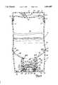
- FIG. 1is perspective view of the dispensing container of the present invention shown with a travel cap supported at a closed end of the container.
- FIG. 1Ais an exploded view of the dispensing container as shown in FIG. 1.
- FIG. 2is a plan view of a dispensing end of the container of FIG. 1 illustrating a dispensing valve.
- FIG. 3is a perspective view of the dispensing container similar to FIG. 1 with the travel cap shown sealing the dispensing valve for transport.
- FIG. 4is a cross-sectional view of the travel cap.
- FIG. 5is a cross-sectional view of the dispensing container, similar to FIG. 1, with the travel cap being supported at the closed end.
- FIG. 6is a cross-sectional view of the dispensing container, similar to FIG. 3, with the travel cap shown sealing the dispensing valve for transport.
- FIG. 7is an exploded detailed view of the dispensing valve.
- FIGS. 1-3disclose a dispensing container 10 of the present invention.
- dispensing container 10includes a travel cap 12, a bottle 16, a dispensing valve 18, and base cap 20.
- the dispensing valve 18selectively dispenses flowable content such as soap, shampoo and other health and beauty products from the bottle 16 of the container 10 when the bottle 16 is squeezed.
- the valve 18restricts the flow of content from the bottle 16 when the bottle 16 is not being squeezed.
- the base cap 20 and dispensing valve 18are both at a dispensing end 22 of the container 10 so that the base cap 20 supports the container 10 in an upright inverted position as shown in FIG. 1 to define the base of the container.
- gravityforces the contents in the dispensing container 10 toward the dispensing valve 18 for immediate discharge when pressure is applied to the container 10.
- This featureis particularly useful as the container is emptied, since it would take longer and longer for content to be dispensed if the container were supported at the opposite end of a dispensing opening.
- travel cap 12is selectively positioned at a closed end 23 of the bottle 16 of the container 10 (FIG. 1) and at the dispensing end 22 (FIG. 3).
- the travel cap 12is positioned at the closed end 23 as shown in FIG. 1 when content is to be dispensed through the dispensing valve 18 and at the dispensing end 22 to seal the dispensing valve 18 for transport as shown in FIG. 3.
- the base cap 20is frusto-conical shaped and includes a through opening 24, a drain hole 26, a drain slot 28, a rim ridge 32 and a threaded receptacle 34 (shown in FIG. 1A).
- the base cap 20is formed of a cup-like member having a circular face 36, a sloped cylindrical side wall 38 and a rim 40 defining a housing structure.
- the side wall 38extends from the circular face 36 and is sloped outwardly so that the diameter of the rim 40 is larger than the diameter of the circular face 36.
- the threaded receptacle 34includes a threaded cylindrical wall 42 which extends essentially perpendicularly from face 36.
- rim ridge 32 of base cap 20circumferentially extends about an outer periphery of the face 36 to define an elevated support ridge and a recessed end surface 44.
- the drain slot 28extends through the rim ridge 32 between the recessed end surface 44 and an outer surface of the container 10 to fluidly connect the end surface 44 to the outer surface of the container 10.
- the drain slot 28allows for drainage of fluid trapped under the rim ridge 32 when the dispensing container 10 is supported by the base cap 20, so that mildew and other bacteria is not allowed to grow and collect between the recessed end surface 44 and the rim ridge 32.
- the dispensing valve 18is formed of a silicone membrane 46 including a cross-shaped slit 48.
- the cross shaped slit 48is cut through the silicone membrane 46 to define a plurality of relatively small flaps 50.
- the flaps 50are aligned parallel to the silicone membrane 46 to define a closed position for the dispensing valve 18.
- the flaps 50open such that the flaps 50 are angled relative to the silicone membrane 46 to define an open position for the dispensing valve 18.
- FIG. 4is a cross sectional view of the travel cap 12.
- the travel cap 12is formed of a cup-shaped member having a circular face 58, a cylindrical wall 60, and a rim 62.
- the cylindrical wall 60extends from the periphery of the face 58.
- the wall 60is sloped from the face 58 toward rim 62, to define a larger diameter for the rim 62 than the face 58.
- the rim 62 and wall 60are sized to allow the closed end 23 of the container 10 to be inserted into the interior of the travel cap 12.
- the travel cap 12includes a plurality of lugs 66 (which extend about an inner surface of the cylindrical wall 60) and a plug 68.
- the plug 68includes a circular ring 70 and a lip 72.
- the circular ring 70extends essentially perpendicularly from the face 58 of the travel cap 12.
- Lip 72extend about the periphery of the ring 70 and includes a sloped insertion face 74 and a sloped release face 76.
- FIGS. 5 and 6are cross-sectional views of the container 10 of FIGS. 1 and 3, respectively.
- FIG. 5illustrates the dispensing container 10 with the travel cap 12 supported at the closed upper end 23.
- FIG. 6is a cross-sectional view of the dispensing container 10 with the travel cap 12 sealing the dispensing valve 18 at the dispensing end 22.
- the travel cap 12is secured to the closed end 23 as shown in FIG. 5 by cooperation of the lugs 66 of the travel cap 12 and the circumferential groove 54 extending about the periphery of the closed end 23.
- Lip 52is a curvedly shaped end about the periphery of the closed end 23. Lip 52 flexes the cylindrical wall 60 of the travel cap 12 as the travel cap 12 is forced onto the closed end 23 of the dispensing container 10 to snap fit the lugs 66 into groove 54 of the dispensing container 10.
- a recessed ledge 77 between the bottle 16 and the closed end 23 of the dispensing container 10accommodates the rim 62 of the travel cap 12.
- the recessed ledge 77is dimensioned similar to the thickness of the wall 60 of the travel cap 12 to accommodate the travel cap 12.
- the userpulls and gently twists the travel cap 12 from the closed end 23 to force the travel cap 12 about the curvedly shaped lip 52 to release the lugs 66 of the travel cap 12 from groove 54 of the closed end 23.
- the lugs 66 of travel cap 12are positioned a sufficient distance from the face 58 of the travel cap 12 to allow for clearance between an end face of the closed end 23 and the plug 68 of the travel cap 12.
- the end face of the closed end 23is concave-shaped having a center dip 78.
- the bottle 16 of the dispensing container 10includes an inner cavity 79, a main container segment 80, shoulder 82, having an upper and lower portion 82A and 82B, a threaded neck 86 and mouth 88.
- Flowable contentis filled into the inner cavity 79 of the main container segment 80 of the bottle 16 through mouth 88.
- the main container segment 80is generally cylindrically and slightly concave-shaped.
- the neck 86has a smaller diameter than the main container segment 80 and is connected to the main container segment 80 by the shoulder 82.
- Upper shoulder portion 82Ais adjacent to the main container segment 80 and the lower shoulder portion 82B is adjacent to the neck 86.
- a recessed ledge 89connects the main container segment 80 to the upper shoulder portion 82A.
- the base cap 20is screwed to the bottle 16 to form the dispensing container 10 via cooperation of the threaded receptacle 34 of the base cap 20 and the threaded neck 86 of the bottle 16.
- the depth of the base cap 20is sufficient so that when the neck 86 of the bottle 16 is inserted into receptacle 34 of the base cap 20, the housing (face 36 and cylindrical wall 38) of the base cap 20 encloses the neck 86 and shoulder 82 of the bottle 16 to provide a cover structure for the threaded neck 86 and shoulder 82 of the bottle 16.
- the through opening 24 of the base cap 20is smaller than the mouth 88 of the bottle 16 and aligned therewith when the base cap 20 is screwed to bottle 16 to define the dispensing opening. Fluid is dispensed from the inner cavity 79 of the bottle 16 through the dispensing opening (mouth 88 of the bottle 16 and through opening 24 of the base cap 20).
- the dispensing valve 18is seated in the mouth 88 of the bottle 16 to regulate flow of content, such as shampoos and soaps from the inner cavity 79 through the dispensing opening.
- the rim 40 of the base cap 20abuts against the upper shoulder portion 82A and recessed ledge 89 of the bottle 16.
- the recessed ledge 89is sized relative to the width of the cylindrical side wall 38 of the base cap 20 to provide a smooth transition of the housing of the base cap 20 and the main container segment 80 of the bottle 16.
- the enclosure of the base cap 20 about the neck 86 and the shoulder 82 of the bottle 16defines a base cavity or housing cavity 93.
- watermay seep through the abutment of the rim 40 of the base cap 20 and the bottle 16 at the upper shoulder portion 82A into the base cavity 93.
- Drain hole 26extends through face 36 of the base cap 20 to allow fluid trapped in the base cavity 93 to drain so that mildew and bacteria do not grow.
- FIG. 6illustrates the travel cap 12 attached to the base cap 20 to seal the container 10 for transport.
- the interior of the travel cap 12is sized to fit over a lower portion of the base cap 20 and the lugs 66 of travel cap 12 frictionally grip the outer surface of the wall 38 of the base cap 20.
- the ring 70 of the plug 68is formed of a flexible material and is sized for insertion into through opening 24 of the base cap 20 to seal the opening 24.
- the lip 72overhangs from the ring 70 so that the diameter of the lip 72 is slightly larger than the through opening 24.
- the height of the ring 70 between the face 58 of the cap 20 and lip 72is sized so that the ring 70 extends through opening 24 and the lip 72 engages an inner surface of the face 36 of the base cap 20 to snap fit the travel cap 12 to the base cap 20 of the container 10.
- the sloped insertion face 74(best shown in FIG. 4) of lip 72 allows for insertion of the circular ring 70 and lip 72 through the through opening 24.
- the sloped insertion face 74contacts the base cap 20 at the through opening 24 to slightly flex the ring 70 for insertion of the ring 70 and lip 72 through the through opening 24.
- the sloped release face 76(best shown in FIG. 4) is slightly sloped to facilitate removal of the travel cap 12. The sloped release face 76 flexes the ring 70 as the cap 12 is pulled from the base cap 20 so that the ring 70 and lip 72 may be slid through the through opening 24 for removal of the cap 12.
- Dispensing valve 18, as shown in relation to FIGS. 5-7,includes the silicone membrane 46, and a first ring support 96 and a second ring support 98.
- the silicone membrane 46is supported between the first ring support 96 and the second ring support 98.
- the silicone membrane 46is preformed into a cup-like member having a base 100, cylindrical wall 102, a support ledge 104, and flange 106.
- the cylindrical wall 102extends from the base 100.
- the support ledge 104extends perpendicularly from an open end of the cylindrical wall 102 (opposite the base 100) about the periphery thereof.
- Flange 106extends essentially perpendicularly from ledge 104.
- the cross slit 48is stamped at the base 100 of the cup-like member.
- the first ring support 96includes a flexible fit ring 108, a flow gate 110, flow gate support legs 112, a flow gate support ring 114, recess 116 (shown in FIGS. 5 & 6) and ring groove 118.
- the second ring support 98includes ring ridge 120 and tongue 122. As best shown in FIGS. 5-6, recess 116 of the first ring support 96 is sized to accommodate and is aligned with flange 106 of the silicone membrane 46. Ring ridge 120 of the second ring support 98 snap fits into ring groove 118 of the first ring support 96 to connect the first and second ring supports 96 and 98 to support the ledge 104 of the silicone membrane 46 therebetween.
- the fit ring 108 of the first ring support 96is dimensioned similar to the mouth 88 of the bottle 16. When assembled, the first ring support 96 is inserted into the mouth 88 so that the fit ring 108 fictionally engages the neck 86 of the bottle 16 to secure the dispensing valve 18 relative to the mouth 88 of bottle 16.
- the second ring support 98is dimensioned similar to an outer surface of the neck 86 of the bottle 16. When assembled, the second ring support 98 is seated at an opened end of the neck 86 of the bottle 16. As shown in FIGS. 5 & 6, when the base cap 20 is screwed to the neck 86 of the bottle 16, a portion of the face 36 and a portion of the cylindrical wall 42 of the receptacle 34 of the base cap 20 abut against the second ring support 98 to the lock the dispensing valve 18 within the mouth 88 of the bottle 16.
- the second ring support 98includes a circular tongue 122 which is sized to insert into a corresponding circumferential groove 124 formed about the cylindrical wall 42 of the receptacle 34 of the base cap 20.
- the flow gate 110is a circular plate dimensioned smaller than the diameter of the base 100 of the silicone membrane 46.
- the flow gate 100is supported adjacent to the silicone membrane 46 in the mouth 88 of the bottle 16 to control the flow force of content directly toward the slit 48 to prevent unwanted seepage through the slit 48 of the silicone membrane 46.
- the flow gate 110is supported by the first ring support 96 by the flow gate support ring 114.
- Legs 112connect the flow gate 110 to the flow gate support ring 114. The legs 112 are spaced to allow fluid to flow past the flow gate 110 to be dispensed through the dispensing opening.
- the cap 12, bottle 16 and base cap 20are preferably formed of a high density polyethylene material.
- the silicone membrane 46 and slit 48are dimensioned to restrict flow of content from the inner cavity 79 of the container 10 until the container 10 is squeezed to dispense content.
- a dispensing container 10having a longitudinal axis along an extent of the container and a diametric axis perpendicular to the longitudinal axis, may be constructed according to the present invention as follows.
- the bottle 16 of the containerincludes a main container segment 80 having a center portion having a diameter A of approximately 2.1 inches and opposed end portions having a diameter B of approximately 2.25 inches to define the concaved shape therefor.
- the neck 86 of the bottle 16has an outer diameter of approximately 0.85 inches and the mouth 88 of the bottle 16 has a diameter of approximately 0.72 inches.
- the upper shoulder portion 82A, adjacent the recessed ledge 89includes a rounded edge having a radius C of approximately 0.1 inches and is slightly sloped, at an angle D of approximately 5 degrees relative to the longitudinal axis toward the lower shoulder portion 82B.
- the diameter of the upper shoulder portion 82A at the recessed ledge 89is approximately 2.1 inches.
- the shoulder 82is sloped between the upper shoulder portion 82A and the lower shoulder portion 82B at an angle E of about 30 degrees relative to the diametric axis of the bottle 16 to connect the main container segment 80 and the neck 86 of the bottle 16.
- the diameter F of the closed end 23is approximately 2.1 inches.
- the sides of the groove 54 of the closed end 23have a length G of approximately 0.04 inches, and the width H of a base of the groove 54 is approximately 0.05 inches.
- the sides of the groove 54are formed at an angle I of about 45 degrees, relative to the diametric axis of the bottle 16.
- the lip 52 of the closed end 23includes a rounded end having a radius J of approximately 0.15 inches and a side edge which is sloped inwardly from the groove 54 at an angle K of approximately 5 degrees relative to the longitudinal axis of the bottle 16.
- the center dip 78 of the closed end 23has approximately a 0.1 inch depth.
- the overall height of the bottle 16is approximately 6.2 inches.
- the height of the main container segment 80is approximately 4.62 inches
- shoulder 82is approximately 0.55 inches
- neck 86is approximately 0.65 inches
- closed end 23is 0.40 inches
- lip 52is approximately 0.19 inches.
- the height of shoulder portion 82Ais approximately 0.19 inches
- the diameter of the through opening 24 of the base cap 20is approximately 0.47 inches and the diameter of the rim 40 of the base cap 20 is 2.2 inches.
- the thickness of cylindrical sidewall 38is approximately 0.045 inches.
- the height of the base cap 20is 1.375 inches and the height of the wall 42 of the receptacle 34 is approximately 0.8 inches.
- the height of the base cap 20 and the extent of the wall 42 of the receptacle 34accommodate for the valve 18 and allow the rim 40 of the base cap 20 to seat at the recessed ledge 89 of the bottle 16.
- the wall 38 of the base cap 20is sloped outwardly from the face 36 toward rim 40 at an angle L of about 5 degrees relative to the longitudinal axis.
- the height of the rim ridge 32 at the periphery of the face 36 of the base cap 20is approximately 0.025 inches.
- the drain holeis approximately 0.080 inches in diameter.
- the width of the drain slot 28is approximately 0.1 inches.
- the diameter of the travel cap 12 at the rim 62is approximately 2.2 inches.
- the height of the travel cap 12is approximately 0.575 inches.
- the wall 60 of the travel cap 12is sloped outwardly from the face 58 to the rim 62 at an angle M of 5 degrees relative to the longitudinal axis.
- the height of the ring 70 and lip 72 of plug 68is approximately 0.125 inches.
- the lugs 66are positioned a distance N of approximately 0.0625 inches below the rim 62 of travel cap 12.
- the thickness O of the lugs 66is approximately 0.11 inches and thickness P of the lugs 66 is approximately 0.05 inches.
- the dispensing container 10includes a travel cap 12 which snap fits to the closed end 23 of the container 10 for normal operation.
- the travel cap 12fits on the closed end 23 of the container out of the way of the dispensing valve 18 so that once the container is squeezed, content will be dispensed from the inner cavity 79. Since the travel cap 12 snap fits to the closed end 23 of the container 10, it will not be lost during non-use of the travel cap 12.
- the plug 68 of the travel cap 12fits relative to the through opening 24 of the base cap 20 to seal the valve 18 so that contents will not leak from the container 10 during transport.
Landscapes
- Engineering & Computer Science (AREA)
- Mechanical Engineering (AREA)
- Ceramic Engineering (AREA)
- Closures For Containers (AREA)
Abstract
Description
Claims (20)
Priority Applications (1)
| Application Number | Priority Date | Filing Date | Title |
|---|---|---|---|
| US08/476,858US5655687A (en) | 1995-06-07 | 1995-06-07 | Base end dispensing container with travel cap |
Applications Claiming Priority (1)
| Application Number | Priority Date | Filing Date | Title |
|---|---|---|---|
| US08/476,858US5655687A (en) | 1995-06-07 | 1995-06-07 | Base end dispensing container with travel cap |
Publications (1)
| Publication Number | Publication Date |
|---|---|
| US5655687Atrue US5655687A (en) | 1997-08-12 |
Family
ID=23893548
Family Applications (1)
| Application Number | Title | Priority Date | Filing Date |
|---|---|---|---|
| US08/476,858Expired - LifetimeUS5655687A (en) | 1995-06-07 | 1995-06-07 | Base end dispensing container with travel cap |
Country Status (1)
| Country | Link |
|---|---|
| US (1) | US5655687A (en) |
Cited By (50)
| Publication number | Priority date | Publication date | Assignee | Title |
|---|---|---|---|---|
| US5868288A (en)* | 1997-02-21 | 1999-02-09 | Bristol-Myers Squibb Company | Dispensing container with concealed lugs |
| GB2330577A (en)* | 1997-10-21 | 1999-04-28 | Coda Plastics Ltd | Dispensing valve with a slitted diaphragm and retention ring |
| GB2331069A (en)* | 1997-09-09 | 1999-05-12 | Johnson & Johnson Consumer | Tapered closure |
| US6010042A (en)* | 1998-10-27 | 2000-01-04 | Boucher; Mark | Base end dispensing container with top end valve operator |
| US6062436A (en)* | 1998-04-02 | 2000-05-16 | Owens-Illinois Closure Inc. | Flexible vented self-sealing dispensing valve |
| US6142343A (en)* | 1998-12-30 | 2000-11-07 | Steris Inc | Cap and dust cover for an antiseptic soap dispenser |
| USD448242S1 (en) | 1999-12-30 | 2001-09-25 | Johnson & Johnson Consumer Companies, Inc. | Trainer cup |
| USD448976S1 (en) | 1999-12-30 | 2001-10-09 | Johnson & Johnson Consumer Companies, Inc. | Pinched trainer cup |
| USD450535S1 (en) | 1999-12-30 | 2001-11-20 | Mcdonough Justin E. | Trainer cup |
| US20020008117A1 (en)* | 1999-10-09 | 2002-01-24 | Gent-I-Kleen Products Incorporated | Soap dispenser for soap of different viscosity |
| US20020074367A1 (en)* | 2000-12-18 | 2002-06-20 | Kevin Kawakita | Gravity-fed liquid chemical dispenser bottle |
| WO2002081319A1 (en)* | 2001-03-30 | 2002-10-17 | World Technical Service Co., Ltd. | Delivery switching type cap device |
| US6494346B2 (en) | 2001-01-25 | 2002-12-17 | Seaquist Closures Foreign, Inc. | Inverted package dispensing system |
| WO2003029088A1 (en)* | 2001-10-04 | 2003-04-10 | Xavier Agramont Cruanyes | Container for dispensing shampoo, gel and other similar products |
| US20030121876A1 (en)* | 2001-12-31 | 2003-07-03 | Pechiney Plastic Packaging, Inc. | Waterguard tube |
| US20040000566A1 (en)* | 2002-06-27 | 2004-01-01 | Adam Lowry | Bottom-dispensing liquid soap dispenser |
| US20040065696A1 (en)* | 2002-10-03 | 2004-04-08 | Fletcher Alan D. | Dispenser cap |
| US20050124945A1 (en)* | 2002-12-09 | 2005-06-09 | Powers Jeffrey L. | Wearable skin treatment device |
| US20060243756A1 (en)* | 2000-12-18 | 2006-11-02 | Kevin Kawakita | Gravity-fed liquid chemical dispensing bottle |
| US20070267444A1 (en)* | 2006-05-05 | 2007-11-22 | De Buzzaccarini Francesco | Concentrated compositions contained in bottom dispensing containers |
| US20070270325A1 (en)* | 2006-05-05 | 2007-11-22 | De Buzzaccarini Francesco | Gel compositions contained in bottom dispensing containers |
| US20080015135A1 (en)* | 2006-05-05 | 2008-01-17 | De Buzzaccarini Francesco | Compact fluid laundry detergent composition |
| WO2007130568A3 (en)* | 2006-05-05 | 2008-01-24 | Procter & Gamble | Fabric treatment dispensing package |
| US20080032909A1 (en)* | 2006-05-05 | 2008-02-07 | De Buzzaccarini Francesco | Compact fluid laundry detergent composition |
| US20080035677A1 (en)* | 2004-09-09 | 2008-02-14 | Daansen Warren S | Nozzle tip with slit valve for fluid dispenser |
| US20080230569A1 (en)* | 2006-11-07 | 2008-09-25 | Mcconville Su Yon | Package comprising push-pull closure and slit valve |
| US20090152286A1 (en)* | 2007-12-13 | 2009-06-18 | Wilson Kelce S | Drainable cap for invertible containers |
| US20110290752A1 (en)* | 2010-05-27 | 2011-12-01 | Yeager Don F | Inverted bottle assembly |
| EP1873068A3 (en)* | 2006-06-30 | 2012-08-22 | H. J. Heinz Co. | Condiment bottle |
| US20130306676A1 (en)* | 2012-05-21 | 2013-11-21 | The Coca-Cola Company | Bag in Box Cleanable Connector System |
| US20130327794A1 (en)* | 2012-05-21 | 2013-12-12 | The Coca-Cola Company | Bag in Box Cleanable Connector System Having Conical Plunger |
| US20140246458A1 (en)* | 2013-03-01 | 2014-09-04 | Fundametal Designs Inc. | Stackable container body |
| US8844767B1 (en)* | 2012-07-06 | 2014-09-30 | Daisy Brand, LLC | Food containment and delivery system |
| WO2016057623A1 (en) | 2014-10-07 | 2016-04-14 | The Procter & Gamble Company | Method of pre-treating articles to be washed in a dishwashing machine |
| USD756234S1 (en) | 2014-09-10 | 2016-05-17 | Celgene Corporation | Bottle with cap |
| WO2016138028A1 (en)* | 2015-02-23 | 2016-09-01 | The Sun Products Corporation | Inverted bottle dispensing systems and methods |
| USD767405S1 (en) | 2015-09-21 | 2016-09-27 | Celgene Corporation | Bottle with cap |
| US9598209B1 (en) | 2014-07-22 | 2017-03-21 | Daisy Brand, LLC | Cap and spout assembly with positive orientation features |
| US20180029863A1 (en)* | 2016-07-29 | 2018-02-01 | Berry Plastics Corporation | Liquid dispenser |
| USD830195S1 (en) | 2017-08-24 | 2018-10-09 | Wiesman Holdings, LLC | Gel container |
| US20190161253A1 (en)* | 2017-11-30 | 2019-05-30 | The Procter & Gamble Company | Liquid dispenser for an inverted container |
| USD852646S1 (en) | 2018-05-01 | 2019-07-02 | Wiesman Holdings, LLC | Gel container |
| US10369800B2 (en) | 2015-07-31 | 2019-08-06 | Hewlett-Packard Development Company, L.P. | Printing fluid container |
| USD860003S1 (en) | 2018-05-01 | 2019-09-17 | Wiesman Holdings, LLC | Gel container |
| US20190358667A1 (en)* | 2017-10-23 | 2019-11-28 | Aptargroup, Inc. | Valve |
| WO2021083786A1 (en)* | 2019-10-30 | 2021-05-06 | Unilever Ip Holdings B.V. | Closure for a bottle |
| USD920129S1 (en) | 2018-06-26 | 2021-05-25 | Cheer Pack North America | Inverted pouch |
| US20210339909A1 (en)* | 2012-08-28 | 2021-11-04 | Robert Turcotte | Recessed Container Closure and Method of Increasing Advertising Space on a Container using a Recessed Container Closure |
| US11465813B2 (en) | 2019-07-30 | 2022-10-11 | Campbell Soup Company | Multi-phase squeeze-dispensable food products |
| US11873133B2 (en) | 2021-04-20 | 2024-01-16 | Drug Plastics & Glass Company, Inc. | Bottle, injection blow molding core rod for the bottle and related method |
Citations (8)
| Publication number | Priority date | Publication date | Assignee | Title |
|---|---|---|---|---|
| US1426846A (en)* | 1921-09-02 | 1922-08-22 | Craig Robert John Edward | Container for dispensing liquids |
| US4969581A (en)* | 1989-08-08 | 1990-11-13 | The Procter & Gamble Company | Unequivocal bottom delivery container with self-sealing valve |
| US5033655A (en)* | 1989-02-15 | 1991-07-23 | Liquid Molding Systems Inc. | Dispensing package for fluid products and the like |
| US5213236A (en)* | 1991-12-06 | 1993-05-25 | Liquid Molding Systems, Inc. | Dispensing valve for packaging |
| US5337877A (en)* | 1989-07-28 | 1994-08-16 | Mars, Inc. | Coin validators |
| US5388712A (en)* | 1993-07-19 | 1995-02-14 | Norvey, Inc. | Squeeze bottle top with integral closure holder |
| US5409144A (en)* | 1991-12-06 | 1995-04-25 | Liquid Molding Systems Inc. | Dispensing valve for packaging |
| US5542586A (en)* | 1994-10-14 | 1996-08-06 | Lever Brothers Company, Division Of Conopco, Inc. | Detergent dispenser |
- 1995
- 1995-06-07USUS08/476,858patent/US5655687A/ennot_activeExpired - Lifetime
Patent Citations (10)
| Publication number | Priority date | Publication date | Assignee | Title |
|---|---|---|---|---|
| US1426846A (en)* | 1921-09-02 | 1922-08-22 | Craig Robert John Edward | Container for dispensing liquids |
| US5033655A (en)* | 1989-02-15 | 1991-07-23 | Liquid Molding Systems Inc. | Dispensing package for fluid products and the like |
| US5337877A (en)* | 1989-07-28 | 1994-08-16 | Mars, Inc. | Coin validators |
| US4969581A (en)* | 1989-08-08 | 1990-11-13 | The Procter & Gamble Company | Unequivocal bottom delivery container with self-sealing valve |
| US5213236A (en)* | 1991-12-06 | 1993-05-25 | Liquid Molding Systems, Inc. | Dispensing valve for packaging |
| US5339995A (en)* | 1991-12-06 | 1994-08-23 | Liquid Molding Systems, Inc. | Dispensing valve for packaging |
| US5409144A (en)* | 1991-12-06 | 1995-04-25 | Liquid Molding Systems Inc. | Dispensing valve for packaging |
| US5439143A (en)* | 1991-12-06 | 1995-08-08 | Liquid Molding Systems, Inc. | Dispensing valve for packaging |
| US5388712A (en)* | 1993-07-19 | 1995-02-14 | Norvey, Inc. | Squeeze bottle top with integral closure holder |
| US5542586A (en)* | 1994-10-14 | 1996-08-06 | Lever Brothers Company, Division Of Conopco, Inc. | Detergent dispenser |
Non-Patent Citations (6)
| Title |
|---|
| Closure A as shown in photographs 1 2, (prior art).* |
| Closure A as shown in photographs 1-2, (prior art). |
| Closure B as shown in photographs 1 3, (prior art).* |
| Closure B as shown in photographs 1-3, (prior art). |
| Closure C as shown in photographs 1 3, (prior art).* |
| Closure C as shown in photographs 1-3, (prior art). |
Cited By (77)
| Publication number | Priority date | Publication date | Assignee | Title |
|---|---|---|---|---|
| US5868288A (en)* | 1997-02-21 | 1999-02-09 | Bristol-Myers Squibb Company | Dispensing container with concealed lugs |
| GB2331069A (en)* | 1997-09-09 | 1999-05-12 | Johnson & Johnson Consumer | Tapered closure |
| GB2330577A (en)* | 1997-10-21 | 1999-04-28 | Coda Plastics Ltd | Dispensing valve with a slitted diaphragm and retention ring |
| US6062436A (en)* | 1998-04-02 | 2000-05-16 | Owens-Illinois Closure Inc. | Flexible vented self-sealing dispensing valve |
| US6298554B1 (en) | 1998-04-02 | 2001-10-09 | Owens-Illinois Closure Inc. | Flexible vented self-sealing dispensing valve |
| US6010042A (en)* | 1998-10-27 | 2000-01-04 | Boucher; Mark | Base end dispensing container with top end valve operator |
| US6142343A (en)* | 1998-12-30 | 2000-11-07 | Steris Inc | Cap and dust cover for an antiseptic soap dispenser |
| US20020008117A1 (en)* | 1999-10-09 | 2002-01-24 | Gent-I-Kleen Products Incorporated | Soap dispenser for soap of different viscosity |
| USD450535S1 (en) | 1999-12-30 | 2001-11-20 | Mcdonough Justin E. | Trainer cup |
| USD448242S1 (en) | 1999-12-30 | 2001-09-25 | Johnson & Johnson Consumer Companies, Inc. | Trainer cup |
| USD452116S1 (en) | 1999-12-30 | 2001-12-18 | Mcdonough Justin E. | Trainer cup |
| USD452415S1 (en) | 1999-12-30 | 2001-12-25 | Mcdonough Justin E. | Pinched trainer cup |
| USD463216S1 (en) | 1999-12-30 | 2002-09-24 | Johnson & Johnson Consumer Companies, Inc. | Trainer cup |
| USD448976S1 (en) | 1999-12-30 | 2001-10-09 | Johnson & Johnson Consumer Companies, Inc. | Pinched trainer cup |
| US20060243756A1 (en)* | 2000-12-18 | 2006-11-02 | Kevin Kawakita | Gravity-fed liquid chemical dispensing bottle |
| US20020074367A1 (en)* | 2000-12-18 | 2002-06-20 | Kevin Kawakita | Gravity-fed liquid chemical dispenser bottle |
| US6494346B2 (en) | 2001-01-25 | 2002-12-17 | Seaquist Closures Foreign, Inc. | Inverted package dispensing system |
| WO2002081319A1 (en)* | 2001-03-30 | 2002-10-17 | World Technical Service Co., Ltd. | Delivery switching type cap device |
| WO2003029088A1 (en)* | 2001-10-04 | 2003-04-10 | Xavier Agramont Cruanyes | Container for dispensing shampoo, gel and other similar products |
| US20040200859A1 (en)* | 2001-10-04 | 2004-10-14 | Xavier Agramont Cruanyes | Container for dispensing shampoo, gel and other similar products |
| US20030121876A1 (en)* | 2001-12-31 | 2003-07-03 | Pechiney Plastic Packaging, Inc. | Waterguard tube |
| US7204381B2 (en)* | 2001-12-31 | 2007-04-17 | Pechiney Plastic Packaging, Inc. | Waterguard tube |
| WO2004002843A1 (en)* | 2002-06-27 | 2004-01-08 | 1731 Brandhaus, Inc. | Bottom-dispensing liquid soap dispenser |
| US6705492B2 (en)* | 2002-06-27 | 2004-03-16 | Method Products, Inc. | Bottom-dispensing liquid soap dispenser |
| US20040000566A1 (en)* | 2002-06-27 | 2004-01-01 | Adam Lowry | Bottom-dispensing liquid soap dispenser |
| US20040065696A1 (en)* | 2002-10-03 | 2004-04-08 | Fletcher Alan D. | Dispenser cap |
| US20050124945A1 (en)* | 2002-12-09 | 2005-06-09 | Powers Jeffrey L. | Wearable skin treatment device |
| US7316332B2 (en) | 2002-12-09 | 2008-01-08 | Jeffrey Lewis Powers | Wearable skin treatment device |
| US20080035677A1 (en)* | 2004-09-09 | 2008-02-14 | Daansen Warren S | Nozzle tip with slit valve for fluid dispenser |
| US8899449B2 (en)* | 2004-09-09 | 2014-12-02 | Warren S. Daansen | Nozzle tip with slit valve for fluid dispenser |
| US9254498B2 (en) | 2004-09-09 | 2016-02-09 | Warren S. Daansen | Nozzle tip with slit valve for fluid dispenser |
| US9714714B2 (en) | 2004-09-09 | 2017-07-25 | Warren S. Daansen | Nozzle tip with slit valve for fluid dispenser |
| US20070267444A1 (en)* | 2006-05-05 | 2007-11-22 | De Buzzaccarini Francesco | Concentrated compositions contained in bottom dispensing containers |
| US20080029548A1 (en)* | 2006-05-05 | 2008-02-07 | Ann De Wree | Fabric treatment dispensing package |
| US20080032909A1 (en)* | 2006-05-05 | 2008-02-07 | De Buzzaccarini Francesco | Compact fluid laundry detergent composition |
| WO2007130568A3 (en)* | 2006-05-05 | 2008-01-24 | Procter & Gamble | Fabric treatment dispensing package |
| US20080015135A1 (en)* | 2006-05-05 | 2008-01-17 | De Buzzaccarini Francesco | Compact fluid laundry detergent composition |
| JP2009535274A (en)* | 2006-05-05 | 2009-10-01 | ザ プロクター アンド ギャンブル カンパニー | Distributing packaging container for fabric treatment agent |
| US20070270325A1 (en)* | 2006-05-05 | 2007-11-22 | De Buzzaccarini Francesco | Gel compositions contained in bottom dispensing containers |
| EP1873068B1 (en) | 2006-06-30 | 2015-10-21 | H. J. Heinz Co. | Condiment bottle |
| EP1873068A3 (en)* | 2006-06-30 | 2012-08-22 | H. J. Heinz Co. | Condiment bottle |
| US8863991B2 (en) | 2006-06-30 | 2014-10-21 | H.J. Heinz Company | Condiment bottle |
| US7874466B2 (en) | 2006-11-07 | 2011-01-25 | The Procter & Gamble Company | Package comprising push-pull closure and slit valve |
| US20080230569A1 (en)* | 2006-11-07 | 2008-09-25 | Mcconville Su Yon | Package comprising push-pull closure and slit valve |
| US20090152286A1 (en)* | 2007-12-13 | 2009-06-18 | Wilson Kelce S | Drainable cap for invertible containers |
| US20110290752A1 (en)* | 2010-05-27 | 2011-12-01 | Yeager Don F | Inverted bottle assembly |
| US20130306676A1 (en)* | 2012-05-21 | 2013-11-21 | The Coca-Cola Company | Bag in Box Cleanable Connector System |
| US9085399B2 (en)* | 2012-05-21 | 2015-07-21 | The Coca-Cola Company | Bag in box cleanable connector system |
| US9162806B2 (en)* | 2012-05-21 | 2015-10-20 | The Coca-Cola Company | Bag in box cleanable connector system having conical plunger |
| US20130327794A1 (en)* | 2012-05-21 | 2013-12-12 | The Coca-Cola Company | Bag in Box Cleanable Connector System Having Conical Plunger |
| US8844767B1 (en)* | 2012-07-06 | 2014-09-30 | Daisy Brand, LLC | Food containment and delivery system |
| US20210339909A1 (en)* | 2012-08-28 | 2021-11-04 | Robert Turcotte | Recessed Container Closure and Method of Increasing Advertising Space on a Container using a Recessed Container Closure |
| US20140246458A1 (en)* | 2013-03-01 | 2014-09-04 | Fundametal Designs Inc. | Stackable container body |
| US9598209B1 (en) | 2014-07-22 | 2017-03-21 | Daisy Brand, LLC | Cap and spout assembly with positive orientation features |
| USD756234S1 (en) | 2014-09-10 | 2016-05-17 | Celgene Corporation | Bottle with cap |
| WO2016057623A1 (en) | 2014-10-07 | 2016-04-14 | The Procter & Gamble Company | Method of pre-treating articles to be washed in a dishwashing machine |
| US10131473B2 (en) | 2015-02-23 | 2018-11-20 | Henkel IP & Holding GmbH | Inverted bottle dispensing systems and methods |
| TWI690467B (en)* | 2015-02-23 | 2020-04-11 | 德商漢高智慧財產控股公司 | Inverted bottle dispensing systems and methods |
| WO2016138028A1 (en)* | 2015-02-23 | 2016-09-01 | The Sun Products Corporation | Inverted bottle dispensing systems and methods |
| US10369800B2 (en) | 2015-07-31 | 2019-08-06 | Hewlett-Packard Development Company, L.P. | Printing fluid container |
| USD767405S1 (en) | 2015-09-21 | 2016-09-27 | Celgene Corporation | Bottle with cap |
| US10392239B2 (en)* | 2016-07-29 | 2019-08-27 | Berry Plastics Corporation | Liquid dispenser |
| US10696534B2 (en)* | 2016-07-29 | 2020-06-30 | Berry Plastics Corporation | Liquid dispenser |
| US20190367351A1 (en)* | 2016-07-29 | 2019-12-05 | Berry Plastics Corporation | Liquid dispenser |
| US20180029863A1 (en)* | 2016-07-29 | 2018-02-01 | Berry Plastics Corporation | Liquid dispenser |
| USD830195S1 (en) | 2017-08-24 | 2018-10-09 | Wiesman Holdings, LLC | Gel container |
| US10722915B2 (en)* | 2017-10-23 | 2020-07-28 | Aptargroup, Inc. | Valve |
| US20190358667A1 (en)* | 2017-10-23 | 2019-11-28 | Aptargroup, Inc. | Valve |
| US10611531B2 (en)* | 2017-11-30 | 2020-04-07 | The Procter & Gamble Company | Liquid dispenser for an inverted container |
| US20190161253A1 (en)* | 2017-11-30 | 2019-05-30 | The Procter & Gamble Company | Liquid dispenser for an inverted container |
| USD860003S1 (en) | 2018-05-01 | 2019-09-17 | Wiesman Holdings, LLC | Gel container |
| USD852646S1 (en) | 2018-05-01 | 2019-07-02 | Wiesman Holdings, LLC | Gel container |
| USD920129S1 (en) | 2018-06-26 | 2021-05-25 | Cheer Pack North America | Inverted pouch |
| USD957261S1 (en) | 2018-06-26 | 2022-07-12 | Cheer Pack North America | Inverted pouch |
| US11465813B2 (en) | 2019-07-30 | 2022-10-11 | Campbell Soup Company | Multi-phase squeeze-dispensable food products |
| WO2021083786A1 (en)* | 2019-10-30 | 2021-05-06 | Unilever Ip Holdings B.V. | Closure for a bottle |
| US11873133B2 (en) | 2021-04-20 | 2024-01-16 | Drug Plastics & Glass Company, Inc. | Bottle, injection blow molding core rod for the bottle and related method |
Similar Documents
| Publication | Publication Date | Title |
|---|---|---|
| US5655687A (en) | Base end dispensing container with travel cap | |
| US5626262A (en) | Dispensing container with drainage passages | |
| US5988456A (en) | Closed loop dispensing system | |
| US4739906A (en) | Storage bottle for contact lens cleaning solution having a self closing valve assembly | |
| US5904275A (en) | Closure with self-closing valve | |
| CA2318228C (en) | Dispensing closure for package containing a consumable beverage | |
| US6257463B1 (en) | Aseptic closure for containers of liquids | |
| US8087547B1 (en) | Dispensing devices with bottom outlet for dispensing viscous liquids | |
| US7731066B2 (en) | Closure | |
| RU2295482C2 (en) | Device for distributing and batching | |
| US5029719A (en) | Bottle and cap assembly | |
| JP2002526343A (en) | Lid with container and supply valve and releasable separate internal seal for shipping | |
| IE910773A1 (en) | Squeezable dispenser apparatus | |
| JP2009505920A (en) | Liquid leakage prevention lid | |
| WO1994027881A1 (en) | Dropper dispenser | |
| JP2964167B2 (en) | Automatic closed dispenser for containers containing liquid or pasty products | |
| US5678737A (en) | Vented liquid dispenser and attachment cap therefor | |
| US6431408B1 (en) | Dispensing device and methods | |
| JP3626411B2 (en) | Beverage container | |
| KR100262121B1 (en) | An open and close means attaching to vinyl-case | |
| US5497916A (en) | Liquid dispenser featuring automatic pouring of measured doses | |
| US20020134795A1 (en) | Watertight tube closure | |
| EP0701523A1 (en) | Clog-resistant toggle disk closure | |
| JP2001192051A (en) | Beverage container | |
| JP2002068263A (en) | Cream-like stuff spouting vessel |
Legal Events
| Date | Code | Title | Description |
|---|---|---|---|
| AS | Assignment | Owner name:APTARGROUP, INC., ILLINOIS Free format text:ASSIGNMENT OF ASSIGNORS INTEREST;ASSIGNOR:LAY, DIETER F.;REEL/FRAME:007735/0130 Effective date:19951115 | |
| AS | Assignment | Owner name:REDMOND PRODUCTS, INC., MINNESOTA Free format text:ASSIGNMENT OF ASSIGNORS INTEREST;ASSIGNOR:DRUG PLASTICS & GLASS COMPANY, INC.;REEL/FRAME:007806/0420 Effective date:19960123 Owner name:DRUG PLASTICS & GLASS COMPANY, INC., PENNSYLVANIA Free format text:ASSIGNMENT OF ASSIGNORS INTEREST;ASSIGNOR:BENDER, THOMAS M.;REEL/FRAME:007806/0414 Effective date:19960123 | |
| AS | Assignment | Owner name:REDMOND PRODUCTS, INC., MINNESOTA Free format text:ASSIGNMENT OF ASSIGNORS INTEREST;ASSIGNOR:FITTEN, TIMOTHY E.;REEL/FRAME:008340/0826 Effective date:19961213 | |
| STCF | Information on status: patent grant | Free format text:PATENTED CASE | |
| AS | Assignment | Owner name:BRISTOL-MYERS SQUIBB COMPANY, NEW YORK Free format text:ASSIGNMENT OF ASSIGNORS INTEREST;ASSIGNOR:REDMOND PRODUCTS, INC.;REEL/FRAME:009257/0335 Effective date:19980603 | |
| FEPP | Fee payment procedure | Free format text:PAYOR NUMBER ASSIGNED (ORIGINAL EVENT CODE: ASPN); ENTITY STATUS OF PATENT OWNER: LARGE ENTITY | |
| FPAY | Fee payment | Year of fee payment:4 | |
| AS | Assignment | Owner name:CLAIROL INCORPORATED, CONNECTICUT Free format text:ASSIGNMENT OF ASSIGNORS INTEREST;ASSIGNOR:BRISTOL-MYERS SQUIBB COMPANY;REEL/FRAME:012813/0803 Effective date:20011210 | |
| AS | Assignment | Owner name:SEAQUIST CLOSURES FOREIGN, INC., ILLINOIS Free format text:ASSIGNMENT OF ASSIGNORS INTEREST;ASSIGNOR:APTARGROUP, INC.;REEL/FRAME:014172/0157 Effective date:20030421 | |
| FPAY | Fee payment | Year of fee payment:8 | |
| FPAY | Fee payment | Year of fee payment:12 |