US5654864A - Control method for magnetic stereotaxis system - Google Patents
Control method for magnetic stereotaxis systemDownload PDFInfo
- Publication number
- US5654864A US5654864AUS08/280,124US28012494AUS5654864AUS 5654864 AUS5654864 AUS 5654864AUS 28012494 AUS28012494 AUS 28012494AUS 5654864 AUS5654864 AUS 5654864A
- Authority
- US
- United States
- Prior art keywords
- coil
- magnetic object
- coils
- force
- currents
- Prior art date
- Legal status (The legal status is an assumption and is not a legal conclusion. Google has not performed a legal analysis and makes no representation as to the accuracy of the status listed.)
- Expired - Lifetime
Links
- 230000005291magnetic effectEffects0.000titleclaimsabstractdescription150
- 238000000034methodMethods0.000titleclaimsabstractdescription72
- 230000033912thigmotaxisEffects0.000titleclaimsdescription5
- 230000033001locomotionEffects0.000claimsabstractdescription80
- 230000000694effectsEffects0.000claimsabstractdescription11
- 238000010791quenchingMethods0.000claimsabstractdescription11
- 230000000171quenching effectEffects0.000claimsabstractdescription10
- 238000003384imaging methodMethods0.000claimsabstractdescription6
- 238000004422calculation algorithmMethods0.000claimsdescription20
- 238000004364calculation methodMethods0.000claimsdescription12
- 230000000153supplemental effectEffects0.000claimsdescription9
- 230000008859changeEffects0.000claimsdescription8
- 238000012937correctionMethods0.000claimsdescription8
- 238000012546transferMethods0.000claimsdescription6
- 210000004556brainAnatomy0.000claimsdescription4
- 230000000979retarding effectEffects0.000claimsdescription3
- 238000002591computed tomographyMethods0.000claimsdescription2
- 230000003247decreasing effectEffects0.000claimsdescription2
- 238000012986modificationMethods0.000claimsdescription2
- 230000004048modificationEffects0.000claimsdescription2
- 230000000007visual effectEffects0.000claimsdescription2
- 239000000654additiveSubstances0.000claims1
- 230000000996additive effectEffects0.000claims1
- 230000036962time dependentEffects0.000claims1
- 230000008901benefitEffects0.000abstractdescription2
- 230000006870functionEffects0.000description9
- 238000010586diagramMethods0.000description5
- 230000008569processEffects0.000description4
- 230000002441reversible effectEffects0.000description4
- 238000007792additionMethods0.000description3
- 239000000463materialSubstances0.000description3
- 230000002829reductive effectEffects0.000description3
- 230000009471actionEffects0.000description2
- 238000002474experimental methodMethods0.000description2
- 230000006872improvementEffects0.000description2
- 238000010348incorporationMethods0.000description2
- 210000004872soft tissueAnatomy0.000description2
- 206010028980NeoplasmDiseases0.000description1
- 238000006243chemical reactionMethods0.000description1
- 238000004590computer programMethods0.000description1
- 238000001816coolingMethods0.000description1
- 238000013461designMethods0.000description1
- 238000002594fluoroscopyMethods0.000description1
- 229910052734heliumInorganic materials0.000description1
- 239000001307heliumSubstances0.000description1
- SWQJXJOGLNCZEY-UHFFFAOYSA-Nhelium atomChemical compound[He]SWQJXJOGLNCZEY-UHFFFAOYSA-N0.000description1
- 230000003993interactionEffects0.000description1
- 230000002452interceptive effectEffects0.000description1
- 239000007788liquidSubstances0.000description1
- 238000004519manufacturing processMethods0.000description1
- 230000007246mechanismEffects0.000description1
- 230000004044responseEffects0.000description1
- 230000002123temporal effectEffects0.000description1
- 238000012360testing methodMethods0.000description1
- 238000012549trainingMethods0.000description1
Images


Classifications
- H—ELECTRICITY
- H02—GENERATION; CONVERSION OR DISTRIBUTION OF ELECTRIC POWER
- H02N—ELECTRIC MACHINES NOT OTHERWISE PROVIDED FOR
- H02N15/00—Holding or levitation devices using magnetic attraction or repulsion, not otherwise provided for
- A—HUMAN NECESSITIES
- A61—MEDICAL OR VETERINARY SCIENCE; HYGIENE
- A61B—DIAGNOSIS; SURGERY; IDENTIFICATION
- A61B34/00—Computer-aided surgery; Manipulators or robots specially adapted for use in surgery
- A61B34/70—Manipulators specially adapted for use in surgery
- A61B34/73—Manipulators for magnetic surgery
- A—HUMAN NECESSITIES
- A61—MEDICAL OR VETERINARY SCIENCE; HYGIENE
- A61B—DIAGNOSIS; SURGERY; IDENTIFICATION
- A61B90/00—Instruments, implements or accessories specially adapted for surgery or diagnosis and not covered by any of the groups A61B1/00 - A61B50/00, e.g. for luxation treatment or for protecting wound edges
- A61B90/10—Instruments, implements or accessories specially adapted for surgery or diagnosis and not covered by any of the groups A61B1/00 - A61B50/00, e.g. for luxation treatment or for protecting wound edges for stereotaxic surgery, e.g. frame-based stereotaxis
Definitions
- This inventionrelates to an apparatus for delivering treatment to a specific location in a portion of the body and the method of using this apparatus to achieve this treatment delivery. Specifically, this invention relates to the method, usually written in software for a computer, for controlling currents in coils, which create a force on a magnetic object to achieve this treatment delivery to the specific location in the body part.
- Present methods of controlling the current in multiple-coil force mechanismsusually employ linear methods. That is, power supplies or amplifiers supplying the coil currents act in a direct or a feedback mode to cause the desired magnetic effect in response to some manner by which the effect is detected. This method is often termed the "servo amplifier” method.
- Two examplesare the control of magnetically suspended models in wind tunnels, and the control of magnetically suspended shafts in magnetic bearings.
- the amplifiers and/or power supplies which supply the currentsmust be capable of delivering large amounts of power in order to change the currents with sufficient rapidity to maintain control of the forces on the magnetic objects.
- the difficulty encountered with superconducting coilswhich may quench when the current is changed rapidly. Quenching is the process in a superconducting magnet by which the coil loses its superconductivity and the very rapid power increase boils out much of the liquid helium which is the cooling element of the coil. As a result, superconducting coils are seldom operated in a manner in which the current changes significantly in a short time.
- the invention described belowuses particular relationships between the currents in the various coils, as well as particular time relationships of the currents in the coils to enable control of the magnetic object in small, accurate steps, while avoiding quenching of the coils.
- MMSmagnetic stereotaxis system
- U.S. Pat. Nos. 4,869,247, Video Tumor Fighting System and 5,125,888, Magnetic Stereotactic System for Treatment DeliveryThis embodiment is a cubic array of six superconducting coils moderately foreshortened in one dimension.
- the method of this inventionis based on the use of multiple coils. While the full method modifies the following in a way described later, it is most directly understood on consideration of the effects of a single coil pair and with the magnetic object on their common axis.
- each coil pairone member is the main, or pulling coil, and the other is the supplemental or subsidiary, or pushing coil.
- the magnetic fieldhas the same direction on the two sides of the plane of the coil, while the gradient has the opposite directions. This can be seen in FIG. 1 for either of the coils independently.
- the field B1 and gradient G1result from current in coil 1.
- B2 and G2result from current in coil 2.
- the force on a magnetic objectis proportional to the gradient of the field at the location of the object.
- the direction of the moment of the magnetic objectgives the direction of the force on it, caused by the gradient of the field.
- the direction of the moment of the magnetic objectis governed by and parallel to the direction of the magnetic field, in soft tissue.
- FIGS. 1a and 1bindicate both the Helmholz and the anti-Helmholz arrangements. Shown are the individual magnetic fields and gradients of the two coils, along their common axis, and their combined fields and gradients. This is shown for equal magnitudes or current in the two coils, although in use of the present invention the currents are usually not equal.
- the first practical aspect of this arrangement with currents of equal magnitudesis that only the closest coil of the pair can pull the magnetic object. If the magnetic object is a permanent magnet, it can be oriented initially so that the closest coil would tend to push it, but in practice, the object will not be stable in this orientation, and in soft tissue will reverse its direction before significant force is applied.
- the currentsare generally not equal.
- the case of most difficultyis when the magnetic object must be pulled from the far side of the head.
- the largest currentis in the coil which is farthest from the magnetic object; this is the "main" coil, and it pulls the magnetic object.
- a smaller currentis in the coil closest to the magnetic object, the amount depending on its relative distance to each of the two coils.
- the current in the pushing coilmust always be small enough that the contribution of magnetic field from it will not be as large as the contribution of magnetic field from the coil which must pull the magnetic object. Otherwise, the magnetic object will reverse its orientation and move in a direction opposite the desired one.
- the magnetic fieldessentially falls off inversely as the cube of the distance from the coil, while the gradient falls off inversely as the fourth power of the distance from the coil, facilitates this arrangement.
- the magnetic objectis quite far from the pulling coil, it can still exert a dominant orienting magnetic field, while the much closer coil with much smaller current can exert the dominant gradient, hence force, in the correct direction.
- Such an improvementis possible, even when the current in the pushing coil is kept below the magnitude at which it would reverse the magnetic object orientation.
- a second aspect of this inventionis the control of the magnetic object motion by specially controlled impulsive forces which give precise steps to the motion.
- the force impulse on the magnetic object from the coil pair in questionhas two parts: one is the relatively constant force from the main, pulling coil, the other is a force of short duration from the subsidiary, pushing coil.
- This stepis called "boost".
- boost currentthe typical maximum current in the subsidiary coil (maximum boost current) is 15% of the maximum in the main coil.
- a third element in our control systemallows for a mode of operation in which the subsidiary coil has its current reversed briefly, causing it to pull back on the magnetic object, in effect cancelling the impulse which started the motion.
- This stepis called “halt”, and the subsidiary current during the step is called “halt current”.
- the two coilsare acting in the Helmholz mode.
- the subsidiary coil in halt modeacts to retard motion while the main coil current is being further reduced to below the threshold for a moving force on the magnetic object.
- a fourth element in this inventionis the combination of forces from several coil pairs, in an algorithm which allows interactive control to overcome the lack of sufficient other input information.
- the effects of each coil pairare added in an approximate manner, which can be tested against a firm calculation of the effects of currents in the combined coils. If the calculated result differs too greatly from the intended, the operator can make changes to reduce the difference.
- the inverse problem of electromagnetismis handled by the iteration of a called-for motional distance, the assumption of currents needed to develop the force impulse to give a motional distance step in an oversimplified model, the comparison of the motion to be expected from the calculated force impulse from the assumed currents, and an operator comparison of the actual result of the assumptions with the result intended at the outset.
- the inverse problem of electromagnetismis the problem in which a given field and/or gradient is needed at a point or region, and the problem is to find the sources needed to create that field and/or gradient.
- the direct problem of electromagnetismis simpler: given one or more sources, what is the field and/or gradient at a point or region? The reason the inverse problem is often more difficult is that a particular design of sources (in the present case coils) will require more information than just the field and/or gradient.
- An essential element in this applicationis the production of positional information about the magnetic object before the start of each step. At present this information is developed from biplanar fluoroscopy, but other means could be used.
- the methodis called the Vector Approximation, or Vector Method, and the manner in which this is accomplished is seen in the following description of an example of using the magnetic stereotaxis system (MSS) for moving a magnetic object in the brain.
- MSSmagnetic stereotaxis system
- a set of three additional equationscan be written for the magnetic field components at the location of the magnetic object. Physically, these can be introduced into the solution by requiring that the magnetic field direction be the same as the force direction. However, it can be readily shown that there are regions for the magnetic object, within the coil system, for which this condition requires huge currents in some of the magnets in order to produce small forces. The way the present method avoids this requirement for added information is by approximating the electromagnetic force needed from an input directive on a motional step, then calculating the actual resulting force and the ensuing motional step. From displays of the consequences of these calculations the operator can then judge whether to, and by how much to modify particular coil currents so as to reach acceptable accuracy.
- a combination of vector input and displayed vector calculationis a feasible approximation which constitutes the force decision part of the motion-force algorithm described here.
- Motion of the magnetic objectoccurs in successive steps, each of which is controlled by this algorithm.
- Thishas human input at the start of each motional step: the initial magnetic object direction and distance step command from a mouse or joy stick, displayed on screen as, for instance, a red arrow.
- Specific to the present algorithmis a second human input segment of the control loop: judgment and revision (before execution) when compared with the actual step motion expected from the command as executed by the Vector method.
- a comparison of two arrows, desired move (e.g. red) and "actual" move (e.g. green)allow the judgment.
- the algorithmcalculates needed magnet current levels (with some error) based on the direction and length of the red arrow, and the user can revise the current levels appropriately. It then calculates the actual force which these currents will apply, and using a previously measured force-to-distance transfer function will present the distance and direction to be traveled as the green arrow. It will be recognized that this green arrow calculation is the regular problem of electromagnetism, and need not require any approximation.
- each component of the needed gradientis calculated from currents in the coils for that axis only.
- the x-component of the gradient, G xuses only the x-axis coils
- G yuses only the y-axis coils
- G zuses only the z-axis coils.
- the actual motional regionis relatively a small part of the total volume (within a spherical region less than 20 cm diameter) as compared with the rectangular volume determined by the coil sizes and inter-coil distances (61 cm in this example), the approximation would be expected to be moderately successful, and tests show that to be the case for these dimensions.
- Implicit in the algorithmis the use of the mechanical Distance-to-Force Impulse Transfer Function (DF Trans Fncn) to provide the temporal qualities of the impulse. None else in the algorithm until the very end, where boost logic comes into play, considers any time-dependence. Also implicit in the algorithm is that boost operation is ignored until this last step. These assumptions need involve no approximation, but must be treated empirically. This is the point where results from previous actual experiments are used, and their effectiveness depends heavily on having used a good, representative phantom material.
- DF Trans FncnMechanical Distance-to-Force Impulse Transfer Function
- a control methodpermits the operation of multiple superconducting magnetic coils so as to move a magnetic object to precisely specified locations within the body under command of a physician-operator observing the motion with live fluoroscopic imaging fused with more detailed preoperative imaging of some other kind.
- a computercontains the preoperative images and the fluoroscopic images, as well as the means to effect changes in the coil currents so as to accomplish the desired magnetic object motion and positioning.
- the control methodoperates the coils in pairs on opposite sides of the body in a manner to minimize the necessary current changes, thus avoiding the quenching of the superconducting coils. Combinations of these pairs can execute motion of the magnetic object in any direction in an impulsive manner and with high precision.
- the methodshould function well and provide advantages with coils which are not superconducting as well.
- the methodovercomes the redundance present in the limited constraints given by a simple movement vector by the physician-operator, an effect of the "inverse problem of electromagnetism". Namely, when there are more than three coils acting at one time, the specification of the required three currents is not fully met by the stipulation of the three directional components of a specified motion step.
- FIGS. 1a and 1bare schematic diagrams of the magnitudes and directions of the magnetic field B and the gradient G along the axis between two coils having currents of equal magnitudes but in opposite directions (anti-Helmholz, FIG. 1b), and for currents in the same directions (Helmholz, FIG. 1a).
- FIG. 2is a schematic diagram of the progression in time of the currents in two coils acting as a pair in the manner described, and the force on a magnetic object at a representative point between them. These illustrate the action of the two coils.
- the main coilproduces a sub-threshold force and the subsidiary coil produces a boost, initially to cause magnetic object movement, and finally to halt the movement.
- FIG. 3is a block diagram showing the interaction of various parts of the algorithm which accomplishes the motional step of the magnetic object in one embodiment of the MSS.
- FIG. 4schematically shows a computer screen.
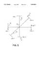
- FIG. 5is a schematic representation of the axes.
- FIGS. 1a and 1bshow the two classical arrangements of a pair of coils having a common axis, and with equal current magnitudes.
- the present control methodis built upon using the second arrangement, as shown in FIG. 1b.
- FIG. 1ashows a Helmholz arrangement.
- the current in the coilsis shown as o for out of the paper and + for into the paper.
- the magnetic fields and gradients along the axisare shown.
- B1 and B2are the magnetic fields contributed by coils 1 and 2, respectively.
- G1 and G2are the gradients of those fields, respectively.
- B and Gare the algebraic sums of those magnetic fields and gradients. In that arrangement the magnitudes of the individual magnetic fields add, while the magnitudes of the gradients subtract.
- FIG. 1bshows an anti-Helmholz arrangement. Symbols are the same as shown in FIG. 1a. Here can be seen that the magnitudes of the magnetic fields subtract, while the magnitudes of the gradients add.
- FIG. 2illustrates the currents and force on the magnetic object as a function of time during the typical operation of a pair of coils for one step of motion.
- the main coil currentis steady until the start of the "halt" or retarding part of the motion cycle. At that time it is ramped to a lower quantity so that the magnetic object, at its new position, will not continue to move.
- the boost or halt currents in the supplemental or subsidiary coilare roughly triangular ramps in time, providing impulsive additions to or subtractions from the nearly steady force due to the main coil.
- That situationis depicted by the dashed line showing threshold. It shows that under such a case the force rises even after the boost current is off, and the magnetic object keeps moving, in a condition called runaway. For that reason, the halt part of the cycle is started at some time after the boost finishes, which reduces the total force below threshold and stabilizes the position of the magnetic object.
- the coilsare in the anti-Helmholz configuration and during the halt motion the coils are in the Helmholz configuration.
- FIG. 3is a block diagram of one mode of using the features discussed in this invention in a computer program to control the set of three coil pairs. The operational details of this diagram are discussed in the algorithm steps below. The following is an example of how this system works. Although this example describes using this method for moving an object in the brain, this method is easily adapted for use with other body parts.
- the surgeon 10views the present magnetic object position 21 on the computer screen 12.
- the object positionis shown superposed on the appropriate preoperative MR/CT scan 13.
- the magnetic object locationhas been mathematically determined from the biplanar fluoroscope images 20, and then superimposed as a symbol (e.g., a pink dot 21) on the MR atlas pages on the screen.
- the userthen inputs the vector position change desired for the seed as the next step. This is shown as the red arrow 23.
- the algorithm 24operates on that information as follows:
- FIG. 5also shows intersecting axes 90, 92, 93.
- the algorithmuses the DFC module to calculate the actual force components that will result from those currents, and thence to get the actual distance to be traveled. This is used in two ways:
- the actual force 69 on the seedis then used to calculate 71 the green arrow 73, showing where the seed will actually go given the currents that have been calculated and then rescaled.
- step 8(b)(1) or 8(b)(2)the complete process iterates from step 1 again.
- the operatoris satisfied with the green arrow, he presses the step execution button.
- the vector boost logic 85supplies the output currents 87 to the controllers. After a short training period, it is surprising how quickly these steps can be iterated.
- the factoris different for each of the three coil axes, and depends on where the seed is located.
- the boostis applied automatically, without separate operator action.
- the distance-to-force transfer functionis constructed with data obtainable by direct experimentation, i.e. by calculable force-impulse distance data taken on axis of one set of coil pairs.
- the force-to-gradient conversionin the vector approximation, is simply division by a number, which is the seed magnetic moment. For one magnetic object in use the magnetic moment is 0.01 A-m 2 .
- the arrow matchingcan be thought of as an iterative procedure. When the operator is satisfied, he presses the execute button. However, he has further control during the step. If, based on the fluoroscope observation the seed looks as if it will go too far, or in an incorrect direction, the halt mode can be invoked at any arbitrary time.
- Sets of superconducting coilsare operated for providing strong force impulses and accurate motion steps of a small magnetic object in the coils combined field, and minimizing the risk of quenching the coils.
- the operationincludes the following steps:
Landscapes
- Health & Medical Sciences (AREA)
- Surgery (AREA)
- Engineering & Computer Science (AREA)
- Life Sciences & Earth Sciences (AREA)
- Biomedical Technology (AREA)
- Public Health (AREA)
- Nuclear Medicine, Radiotherapy & Molecular Imaging (AREA)
- Veterinary Medicine (AREA)
- General Health & Medical Sciences (AREA)
- Heart & Thoracic Surgery (AREA)
- Medical Informatics (AREA)
- Molecular Biology (AREA)
- Animal Behavior & Ethology (AREA)
- Chemical & Material Sciences (AREA)
- Robotics (AREA)
- Combustion & Propulsion (AREA)
- Oral & Maxillofacial Surgery (AREA)
- Pathology (AREA)
- Magnetic Resonance Imaging Apparatus (AREA)
Abstract
Description
Claims (37)
Priority Applications (3)
| Application Number | Priority Date | Filing Date | Title |
|---|---|---|---|
| US08/280,124US5654864A (en) | 1994-07-25 | 1994-07-25 | Control method for magnetic stereotaxis system |
| AU31994/95AAU3199495A (en) | 1994-07-25 | 1995-07-24 | Control method for magnetic stereotaxis system |
| PCT/US1995/009337WO1996003795A1 (en) | 1994-07-25 | 1995-07-24 | Control method for magnetic stereotaxis system |
Applications Claiming Priority (1)
| Application Number | Priority Date | Filing Date | Title |
|---|---|---|---|
| US08/280,124US5654864A (en) | 1994-07-25 | 1994-07-25 | Control method for magnetic stereotaxis system |
Publications (1)
| Publication Number | Publication Date |
|---|---|
| US5654864Atrue US5654864A (en) | 1997-08-05 |
Family
ID=23071788
Family Applications (1)
| Application Number | Title | Priority Date | Filing Date |
|---|---|---|---|
| US08/280,124Expired - LifetimeUS5654864A (en) | 1994-07-25 | 1994-07-25 | Control method for magnetic stereotaxis system |
Country Status (3)
| Country | Link |
|---|---|
| US (1) | US5654864A (en) |
| AU (1) | AU3199495A (en) |
| WO (1) | WO1996003795A1 (en) |
Cited By (154)
| Publication number | Priority date | Publication date | Assignee | Title |
|---|---|---|---|---|
| WO1999012252A1 (en)* | 1997-08-29 | 1999-03-11 | Stereotaxis, Inc. | Method and apparatus for rapidly changing a magnetic field produced by electromagnets |
| WO1999023946A1 (en)* | 1997-11-12 | 1999-05-20 | Stereotaxis, Inc. | Device and method for specifying magnetic field for surgical applications |
| US6015414A (en)* | 1997-08-29 | 2000-01-18 | Stereotaxis, Inc. | Method and apparatus for magnetically controlling motion direction of a mechanically pushed catheter |
| WO2000007652A1 (en) | 1998-08-07 | 2000-02-17 | Regents Of The University Of Minnesota | Mr-visible device for magnetic stereotaxis neurological interventions |
| WO2000023000A1 (en) | 1998-10-16 | 2000-04-27 | Regents Of The University Of Minnesota | Mri and magnetic stereotaxis surgical system |
| WO2000025864A1 (en)* | 1998-11-03 | 2000-05-11 | Stereotaxis, Inc. | Open field system for magnetic surgery |
| US6157853A (en)* | 1997-11-12 | 2000-12-05 | Stereotaxis, Inc. | Method and apparatus using shaped field of repositionable magnet to guide implant |
| US6212419B1 (en) | 1997-11-12 | 2001-04-03 | Walter M. Blume | Method and apparatus using shaped field of repositionable magnet to guide implant |
| US6216026B1 (en)* | 1997-08-20 | 2001-04-10 | U.S. Philips Corporation | Method of navigating a magnetic object, and MR device |
| US6311082B1 (en)* | 1997-11-12 | 2001-10-30 | Stereotaxis, Inc. | Digital magnetic system for magnetic surgery |
| US6463317B1 (en) | 1998-05-19 | 2002-10-08 | Regents Of The University Of Minnesota | Device and method for the endovascular treatment of aneurysms |
| US20020177789A1 (en)* | 2001-05-06 | 2002-11-28 | Ferry Steven J. | System and methods for advancing a catheter |
| US20020186520A1 (en)* | 2001-04-05 | 2002-12-12 | Florida State University Research Foundation, Inc. | Apparatus and method for controlling movement of an object through a medium using a magnetic field |
| US6505062B1 (en) | 1998-02-09 | 2003-01-07 | Stereotaxis, Inc. | Method for locating magnetic implant by source field |
| US20030236542A1 (en)* | 1995-10-13 | 2003-12-25 | Transvascular, Inc. | Methods for bypassing or near-total obstructions in arteries or other anatomical conduits |
| US20040019447A1 (en)* | 2002-07-16 | 2004-01-29 | Yehoshua Shachar | Apparatus and method for catheter guidance control and imaging |
| US6709444B1 (en) | 1996-02-02 | 2004-03-23 | Transvascular, Inc. | Methods for bypassing total or near-total obstructions in arteries or other anatomical conduits |
| US20040138562A1 (en)* | 2002-01-17 | 2004-07-15 | Joshua Makower | Devices, systems and methods for acute or chronic delivery of substances or apparatus to extravascular treatment sites |
| US20040242429A1 (en)* | 2003-05-27 | 2004-12-02 | The University Of Chicago | Superconducting magnetic control system for manipulation of particulate matter and magnetic probes in medical and industrial applications |
| US20050033162A1 (en)* | 1999-04-14 | 2005-02-10 | Garibaldi Jeffrey M. | Method and apparatus for magnetically controlling endoscopes in body lumens and cavities |
| US20050096589A1 (en)* | 2003-10-20 | 2005-05-05 | Yehoshua Shachar | System and method for radar-assisted catheter guidance and control |
| US20050148864A1 (en)* | 2002-04-30 | 2005-07-07 | Slade Robert A. | Method and assembly for magnetic resonance imaging and catheter sterring |
| US20060036163A1 (en)* | 2004-07-19 | 2006-02-16 | Viswanathan Raju R | Method of, and apparatus for, controlling medical navigation systems |
| WO2006018841A2 (en) | 2004-08-16 | 2006-02-23 | Navicath Ltd. | Image-guided navigation for catheter-based interventions |
| US7048716B1 (en) | 1997-05-15 | 2006-05-23 | Stanford University | MR-compatible devices |
| US20060144407A1 (en)* | 2004-07-20 | 2006-07-06 | Anthony Aliberto | Magnetic navigation manipulation apparatus |
| US20060144408A1 (en)* | 2004-07-23 | 2006-07-06 | Ferry Steven J | Micro-catheter device and method of using same |
| US20060173440A1 (en)* | 2001-01-17 | 2006-08-03 | Medtronic Vascular, Inc. | Microcatheter Devices and Methods for Targeted Substance Delivery |
| US20060269108A1 (en)* | 2005-02-07 | 2006-11-30 | Viswanathan Raju R | Registration of three dimensional image data to 2D-image-derived data |
| US20060276867A1 (en)* | 2005-06-02 | 2006-12-07 | Viswanathan Raju R | Methods and devices for mapping the ventricle for pacing lead placement and therapy delivery |
| US20060281989A1 (en)* | 2005-05-06 | 2006-12-14 | Viswanathan Raju R | Voice controlled user interface for remote navigation systems |
| US20060281990A1 (en)* | 2005-05-06 | 2006-12-14 | Viswanathan Raju R | User interfaces and navigation methods for vascular navigation |
| US20060278246A1 (en)* | 2003-05-21 | 2006-12-14 | Michael Eng | Electrophysiology catheter |
| US20070016131A1 (en)* | 2005-07-12 | 2007-01-18 | Munger Gareth T | Flexible magnets for navigable medical devices |
| US20070016006A1 (en)* | 2005-05-27 | 2007-01-18 | Yehoshua Shachar | Apparatus and method for shaped magnetic field control for catheter, guidance, control, and imaging |
| US20070021731A1 (en)* | 1997-11-12 | 2007-01-25 | Garibaldi Jeffrey M | Method of and apparatus for navigating medical devices in body lumens |
| US20070019330A1 (en)* | 2005-07-12 | 2007-01-25 | Charles Wolfersberger | Apparatus for pivotally orienting a projection device |
| US20070021742A1 (en)* | 2005-07-18 | 2007-01-25 | Viswanathan Raju R | Estimation of contact force by a medical device |
| US20070021744A1 (en)* | 2005-07-07 | 2007-01-25 | Creighton Francis M Iv | Apparatus and method for performing ablation with imaging feedback |
| US20070030958A1 (en)* | 2005-07-15 | 2007-02-08 | Munger Gareth T | Magnetically shielded x-ray tube |
| US20070038065A1 (en)* | 2005-07-07 | 2007-02-15 | Creighton Francis M Iv | Operation of a remote medical navigation system using ultrasound image |
| US20070038410A1 (en)* | 2005-08-10 | 2007-02-15 | Ilker Tunay | Method and apparatus for dynamic magnetic field control using multiple magnets |
| US20070038064A1 (en)* | 2005-07-08 | 2007-02-15 | Creighton Francis M Iv | Magnetic navigation and imaging system |
| US20070038075A1 (en)* | 2005-06-23 | 2007-02-15 | Siemens Aktiengesellschaft | Catheter, catheter device, and imaging diagnostic device |
| US20070040670A1 (en)* | 2005-07-26 | 2007-02-22 | Viswanathan Raju R | System and network for remote medical procedures |
| US20070055124A1 (en)* | 2005-09-01 | 2007-03-08 | Viswanathan Raju R | Method and system for optimizing left-heart lead placement |
| US20070060962A1 (en)* | 2005-07-26 | 2007-03-15 | Carlo Pappone | Apparatus and methods for cardiac resynchronization therapy and cardiac contractility modulation |
| US20070060829A1 (en)* | 2005-07-21 | 2007-03-15 | Carlo Pappone | Method of finding the source of and treating cardiac arrhythmias |
| US20070060966A1 (en)* | 2005-07-11 | 2007-03-15 | Carlo Pappone | Method of treating cardiac arrhythmias |
| US20070062547A1 (en)* | 2005-07-21 | 2007-03-22 | Carlo Pappone | Systems for and methods of tissue ablation |
| US20070062546A1 (en)* | 2005-06-02 | 2007-03-22 | Viswanathan Raju R | Electrophysiology catheter and system for gentle and firm wall contact |
| US20070088197A1 (en)* | 2000-02-16 | 2007-04-19 | Sterotaxis, Inc. | Magnetic medical devices with changeable magnetic moments and method of navigating magnetic medical devices with changeable magnetic moments |
| US20070149946A1 (en)* | 2005-12-07 | 2007-06-28 | Viswanathan Raju R | Advancer system for coaxial medical devices |
| US20070161882A1 (en)* | 2006-01-06 | 2007-07-12 | Carlo Pappone | Electrophysiology catheter and system for gentle and firm wall contact |
| US20070167720A1 (en)* | 2005-12-06 | 2007-07-19 | Viswanathan Raju R | Smart card control of medical devices |
| US20070197891A1 (en)* | 2006-02-23 | 2007-08-23 | Yehoshua Shachar | Apparatus for magnetically deployable catheter with MOSFET sensor and method for mapping and ablation |
| US20080006280A1 (en)* | 2004-07-20 | 2008-01-10 | Anthony Aliberto | Magnetic navigation maneuvering sheath |
| US20080015427A1 (en)* | 2006-06-30 | 2008-01-17 | Nathan Kastelein | System and network for remote medical procedures |
| US20080033282A1 (en)* | 2006-08-07 | 2008-02-07 | Bar-Tal Meir | Distortion-immune position tracking using redundant measurements |
| US20080045892A1 (en)* | 2001-05-06 | 2008-02-21 | Ferry Steven J | System and Methods for Advancing a Catheter |
| US20080125646A1 (en)* | 2006-08-21 | 2008-05-29 | Assaf Govari | Distortion-immune position tracking using frequency extrapolation |
| US20080249395A1 (en)* | 2007-04-06 | 2008-10-09 | Yehoshua Shachar | Method and apparatus for controlling catheter positioning and orientation |
| US20080312673A1 (en)* | 2007-06-05 | 2008-12-18 | Viswanathan Raju R | Method and apparatus for CTO crossing |
| US20090088629A1 (en)* | 2007-10-02 | 2009-04-02 | General Electric Company, A New York Corporation | Dynamic reference method and system for interventional procedures |
| US7537570B2 (en) | 2006-09-11 | 2009-05-26 | Stereotaxis, Inc. | Automated mapping of anatomical features of heart chambers |
| US7543239B2 (en) | 2004-06-04 | 2009-06-02 | Stereotaxis, Inc. | User interface for remote control of medical devices |
| US7567233B2 (en) | 2006-09-06 | 2009-07-28 | Stereotaxis, Inc. | Global input device for multiple computer-controlled medical systems |
| US20090275828A1 (en)* | 2008-05-01 | 2009-11-05 | Magnetecs, Inc. | Method and apparatus for creating a high resolution map of the electrical and mechanical properties of the heart |
| US7708696B2 (en) | 2005-01-11 | 2010-05-04 | Stereotaxis, Inc. | Navigation using sensed physiological data as feedback |
| US7747960B2 (en) | 2006-09-06 | 2010-06-29 | Stereotaxis, Inc. | Control for, and method of, operating at least two medical systems |
| US7751867B2 (en) | 2004-12-20 | 2010-07-06 | Stereotaxis, Inc. | Contact over-torque with three-dimensional anatomical data |
| US7757694B2 (en) | 1999-10-04 | 2010-07-20 | Stereotaxis, Inc. | Method for safely and efficiently navigating magnetic devices in the body |
| EP2153860A3 (en)* | 2003-09-16 | 2010-08-11 | Stereotaxis, Inc. | User interface for remote control of medical devices |
| US7818076B2 (en) | 2005-07-26 | 2010-10-19 | Stereotaxis, Inc. | Method and apparatus for multi-system remote surgical navigation from a single control center |
| US7831294B2 (en) | 2004-10-07 | 2010-11-09 | Stereotaxis, Inc. | System and method of surgical imagining with anatomical overlay for navigation of surgical devices |
| WO2011029592A1 (en)* | 2009-09-11 | 2011-03-17 | Eth Zurich | Magnetic manipulation and navigation system for a magnetic element |
| US20110092808A1 (en)* | 2009-10-20 | 2011-04-21 | Magnetecs, Inc. | Method for acquiring high density mapping data with a catheter guidance system |
| US20110091853A1 (en)* | 2009-10-20 | 2011-04-21 | Magnetecs, Inc. | Method for simulating a catheter guidance system for control, development and training applications |
| US20110112396A1 (en)* | 2009-11-09 | 2011-05-12 | Magnetecs, Inc. | System and method for targeting catheter electrodes |
| US7961924B2 (en) | 2006-08-21 | 2011-06-14 | Stereotaxis, Inc. | Method of three-dimensional device localization using single-plane imaging |
| US7966059B2 (en) | 1999-10-04 | 2011-06-21 | Stereotaxis, Inc. | Rotating and pivoting magnet for magnetic navigation |
| US8024024B2 (en) | 2007-06-27 | 2011-09-20 | Stereotaxis, Inc. | Remote control of medical devices using real time location data |
| US8060184B2 (en) | 2002-06-28 | 2011-11-15 | Stereotaxis, Inc. | Method of navigating medical devices in the presence of radiopaque material |
| US8114032B2 (en)* | 2001-05-06 | 2012-02-14 | Stereotaxis, Inc. | Systems and methods for medical device advancement and rotation |
| US8135185B2 (en) | 2006-10-20 | 2012-03-13 | Stereotaxis, Inc. | Location and display of occluded portions of vessels on 3-D angiographic images |
| DE102010051684A1 (en) | 2010-11-17 | 2012-05-24 | Follak Matthias | Device for controlling movements of catheter-like tool within blood vessel of patient for treatment of e.g. cerebral stroke, has electromagnet and catheter whose spatial orientations are controlled using synchronizing control |
| US8196590B2 (en) | 2003-05-02 | 2012-06-12 | Stereotaxis, Inc. | Variable magnetic moment MR navigation |
| US8231618B2 (en) | 2007-11-05 | 2012-07-31 | Stereotaxis, Inc. | Magnetically guided energy delivery apparatus |
| US8244824B2 (en) | 2006-09-06 | 2012-08-14 | Stereotaxis, Inc. | Coordinated control for multiple computer-controlled medical systems |
| US8242972B2 (en) | 2006-09-06 | 2012-08-14 | Stereotaxis, Inc. | System state driven display for medical procedures |
| US8273081B2 (en) | 2006-09-08 | 2012-09-25 | Stereotaxis, Inc. | Impedance-based cardiac therapy planning method with a remote surgical navigation system |
| US8308628B2 (en) | 2009-11-02 | 2012-11-13 | Pulse Therapeutics, Inc. | Magnetic-based systems for treating occluded vessels |
| US8419681B2 (en) | 2002-11-18 | 2013-04-16 | Stereotaxis, Inc. | Magnetically navigable balloon catheters |
| US8437833B2 (en) | 2008-10-07 | 2013-05-07 | Bard Access Systems, Inc. | Percutaneous magnetic gastrostomy |
| US8457714B2 (en) | 2008-11-25 | 2013-06-04 | Magnetecs, Inc. | System and method for a catheter impedance seeking device |
| US8478382B2 (en) | 2008-02-11 | 2013-07-02 | C. R. Bard, Inc. | Systems and methods for positioning a catheter |
| US8480618B2 (en) | 2008-05-06 | 2013-07-09 | Corindus Inc. | Catheter system |
| US8512256B2 (en) | 2006-10-23 | 2013-08-20 | Bard Access Systems, Inc. | Method of locating the tip of a central venous catheter |
| US20130231520A1 (en)* | 2012-02-21 | 2013-09-05 | Gabe Cherian | Imag1 eyes maganetics |
| US8694157B2 (en) | 2008-08-29 | 2014-04-08 | Corindus, Inc. | Catheter control system and graphical user interface |
| US8774907B2 (en) | 2006-10-23 | 2014-07-08 | Bard Access Systems, Inc. | Method of locating the tip of a central venous catheter |
| US8781555B2 (en) | 2007-11-26 | 2014-07-15 | C. R. Bard, Inc. | System for placement of a catheter including a signal-generating stylet |
| US8784336B2 (en) | 2005-08-24 | 2014-07-22 | C. R. Bard, Inc. | Stylet apparatuses and methods of manufacture |
| US8790297B2 (en) | 2009-03-18 | 2014-07-29 | Corindus, Inc. | Remote catheter system with steerable catheter |
| US8801693B2 (en) | 2010-10-29 | 2014-08-12 | C. R. Bard, Inc. | Bioimpedance-assisted placement of a medical device |
| US8849382B2 (en) | 2007-11-26 | 2014-09-30 | C. R. Bard, Inc. | Apparatus and display methods relating to intravascular placement of a catheter |
| USD724745S1 (en) | 2011-08-09 | 2015-03-17 | C. R. Bard, Inc. | Cap for an ultrasound probe |
| US9111016B2 (en) | 2007-07-06 | 2015-08-18 | Stereotaxis, Inc. | Management of live remote medical display |
| US9125578B2 (en) | 2009-06-12 | 2015-09-08 | Bard Access Systems, Inc. | Apparatus and method for catheter navigation and tip location |
| US9211107B2 (en) | 2011-11-07 | 2015-12-15 | C. R. Bard, Inc. | Ruggedized ultrasound hydrogel insert |
| US9220568B2 (en) | 2009-10-12 | 2015-12-29 | Corindus Inc. | Catheter system with percutaneous device movement algorithm |
| USD754357S1 (en) | 2011-08-09 | 2016-04-19 | C. R. Bard, Inc. | Ultrasound probe head |
| US9314222B2 (en) | 2005-07-07 | 2016-04-19 | Stereotaxis, Inc. | Operation of a remote medical navigation system using ultrasound image |
| US9333043B2 (en) | 2013-03-12 | 2016-05-10 | Fetal Care Consultants, LLC | Fetal intervention using magnetically-guided navigation |
| US9339285B2 (en) | 2013-03-12 | 2016-05-17 | Levita Magnetics International Corp. | Grasper with magnetically-controlled positioning |
| US9339206B2 (en) | 2009-06-12 | 2016-05-17 | Bard Access Systems, Inc. | Adaptor for endovascular electrocardiography |
| US9445734B2 (en) | 2009-06-12 | 2016-09-20 | Bard Access Systems, Inc. | Devices and methods for endovascular electrography |
| US9456766B2 (en) | 2007-11-26 | 2016-10-04 | C. R. Bard, Inc. | Apparatus for use with needle insertion guidance system |
| US9492097B2 (en) | 2007-11-26 | 2016-11-15 | C. R. Bard, Inc. | Needle length determination and calibration for insertion guidance system |
| US9521961B2 (en) | 2007-11-26 | 2016-12-20 | C. R. Bard, Inc. | Systems and methods for guiding a medical instrument |
| US9532724B2 (en) | 2009-06-12 | 2017-01-03 | Bard Access Systems, Inc. | Apparatus and method for catheter navigation using endovascular energy mapping |
| US9554716B2 (en) | 2007-11-26 | 2017-01-31 | C. R. Bard, Inc. | Insertion guidance system for needles and medical components |
| US9636031B2 (en) | 2007-11-26 | 2017-05-02 | C.R. Bard, Inc. | Stylets for use with apparatus for intravascular placement of a catheter |
| US9649048B2 (en) | 2007-11-26 | 2017-05-16 | C. R. Bard, Inc. | Systems and methods for breaching a sterile field for intravascular placement of a catheter |
| US9681823B2 (en) | 2007-11-26 | 2017-06-20 | C. R. Bard, Inc. | Integrated system for intravascular placement of a catheter |
| US9833293B2 (en) | 2010-09-17 | 2017-12-05 | Corindus, Inc. | Robotic catheter system |
| US9839372B2 (en) | 2014-02-06 | 2017-12-12 | C. R. Bard, Inc. | Systems and methods for guidance and placement of an intravascular device |
| US9844391B2 (en) | 2009-02-06 | 2017-12-19 | Levita Magnetics International Corp. | Remote traction and guidance system for mini-invasive surgery |
| US9883878B2 (en) | 2012-05-15 | 2018-02-06 | Pulse Therapeutics, Inc. | Magnetic-based systems and methods for manipulation of magnetic particles |
| US9901714B2 (en) | 2008-08-22 | 2018-02-27 | C. R. Bard, Inc. | Catheter assembly including ECG sensor and magnetic assemblies |
| US9962229B2 (en) | 2009-10-12 | 2018-05-08 | Corindus, Inc. | System and method for navigating a guide wire |
| US10010370B2 (en) | 2013-03-14 | 2018-07-03 | Levita Magnetics International Corp. | Magnetic control assemblies and systems therefor |
| US10046139B2 (en) | 2010-08-20 | 2018-08-14 | C. R. Bard, Inc. | Reconfirmation of ECG-assisted catheter tip placement |
| US10252030B2 (en) | 2017-01-17 | 2019-04-09 | Cook Medical Technologies Llc | Handheld magnetic gun for guide wire manipulation |
| US10349890B2 (en) | 2015-06-26 | 2019-07-16 | C. R. Bard, Inc. | Connector interface for ECG-based catheter positioning system |
| US10398393B2 (en) | 2007-10-02 | 2019-09-03 | Stryker European Holdings I, Llc | Dynamic reference method and system for interventional procedures |
| US10449330B2 (en) | 2007-11-26 | 2019-10-22 | C. R. Bard, Inc. | Magnetic element-equipped needle assemblies |
| US10524691B2 (en) | 2007-11-26 | 2020-01-07 | C. R. Bard, Inc. | Needle assembly including an aligned magnetic element |
| US10537713B2 (en) | 2009-05-25 | 2020-01-21 | Stereotaxis, Inc. | Remote manipulator device |
| US10537348B2 (en) | 2014-01-21 | 2020-01-21 | Levita Magnetics International Corp. | Laparoscopic graspers and systems therefor |
| US10639008B2 (en) | 2009-10-08 | 2020-05-05 | C. R. Bard, Inc. | Support and cover structures for an ultrasound probe head |
| US10751509B2 (en) | 2007-11-26 | 2020-08-25 | C. R. Bard, Inc. | Iconic representations for guidance of an indwelling medical device |
| US10820885B2 (en) | 2012-06-15 | 2020-11-03 | C. R. Bard, Inc. | Apparatus and methods for detection of a removable cap on an ultrasound probe |
| US10905511B2 (en) | 2015-04-13 | 2021-02-02 | Levita Magnetics International Corp. | Grasper with magnetically-controlled positioning |
| US10973584B2 (en) | 2015-01-19 | 2021-04-13 | Bard Access Systems, Inc. | Device and method for vascular access |
| US10992079B2 (en) | 2018-10-16 | 2021-04-27 | Bard Access Systems, Inc. | Safety-equipped connection systems and methods thereof for establishing electrical connections |
| US11000207B2 (en) | 2016-01-29 | 2021-05-11 | C. R. Bard, Inc. | Multiple coil system for tracking a medical device |
| US11020137B2 (en) | 2017-03-20 | 2021-06-01 | Levita Magnetics International Corp. | Directable traction systems and methods |
| US11103213B2 (en) | 2009-10-08 | 2021-08-31 | C. R. Bard, Inc. | Spacers for use with an ultrasound probe |
| US11583354B2 (en) | 2015-04-13 | 2023-02-21 | Levita Magnetics International Corp. | Retractor systems, devices, and methods for use |
| US11918314B2 (en) | 2009-10-12 | 2024-03-05 | Corindus, Inc. | System and method for navigating a guide wire |
| US11918315B2 (en) | 2018-05-03 | 2024-03-05 | Pulse Therapeutics, Inc. | Determination of structure and traversal of occlusions using magnetic particles |
| US12171443B1 (en) | 2021-03-09 | 2024-12-24 | Pulse Therapeutics, Inc. | Magnetically controlled flow generation |
| US12262971B2 (en) | 2016-01-08 | 2025-04-01 | Levita Magnetics International Corp. | One-operator surgical system and methods of use |
Families Citing this family (8)
| Publication number | Priority date | Publication date | Assignee | Title |
|---|---|---|---|---|
| EP1115327A4 (en)* | 1998-08-07 | 2007-06-20 | Stereotaxis Inc | Method and apparatus for magnetically controlling catheters in body lumens and cavities |
| DE10341092B4 (en)* | 2003-09-05 | 2005-12-22 | Siemens Ag | Installation for non-contact movement and / or fixation of a magnetic body in a working space using a magnetic coil system |
| DE10340925B3 (en)* | 2003-09-05 | 2005-06-30 | Siemens Ag | Magnetic coil system for non-contact movement of a magnetic body in a working space |
| DE10343494B4 (en)* | 2003-09-19 | 2006-06-14 | Siemens Ag | Magnetically navigable device for use in the field of medical endoscopy |
| DE102005010489B4 (en)* | 2005-03-04 | 2007-02-01 | Siemens Ag | Coil system for non-contact magnetic navigation of a magnetic body in a patient located in a working space |
| DE102005032577B4 (en)* | 2005-07-11 | 2012-09-20 | Siemens Ag | Method for determining the position of an endo robot |
| WO2007077896A1 (en) | 2005-12-27 | 2007-07-12 | Olympus Medical Systems Corp. | Encapsulated medical device guiding system and its control method |
| CN101860321A (en)* | 2010-04-29 | 2010-10-13 | 苏州同心医疗器械有限公司 | Magnetic suspension controller and control method thereof |
Citations (9)
| Publication number | Priority date | Publication date | Assignee | Title |
|---|---|---|---|---|
| US2856238A (en)* | 1955-05-12 | 1958-10-14 | Bill Jack Scient Instr Co | Method and means for suspension of a rotatable object in space |
| US4869247A (en)* | 1988-03-11 | 1989-09-26 | The University Of Virginia Alumni Patents Foundation | Video tumor fighting system |
| US5030196A (en)* | 1980-04-23 | 1991-07-09 | Inoue-Japax Research Incorporated | Magnetic treatment device |
| US5093754A (en)* | 1988-10-18 | 1992-03-03 | Seiko Seiki Kabushiki Kaisha | Control system for a magnetic levitation body |
| US5125888A (en)* | 1990-01-10 | 1992-06-30 | University Of Virginia Alumni Patents Foundation | Magnetic stereotactic system for treatment delivery |
| US5150272A (en)* | 1990-03-06 | 1992-09-22 | Intersonics Incorporated | Stabilized electromagnetic levitator and method |
| US5267091A (en)* | 1991-07-18 | 1993-11-30 | Computer Sciences Corporation | Levitating support and positioning system |
| US5332987A (en)* | 1992-07-31 | 1994-07-26 | Intermagnetics General Corporation | Large gap magnetic suspension system with superconducting coils |
| US5359490A (en)* | 1989-08-24 | 1994-10-25 | Kabushiki Kaisha Yaskawa Denki Seisakusho | Method of controlling moving element of magnetic levitation and transport system |
- 1994
- 1994-07-25USUS08/280,124patent/US5654864A/ennot_activeExpired - Lifetime
- 1995
- 1995-07-24AUAU31994/95Apatent/AU3199495A/ennot_activeAbandoned
- 1995-07-24WOPCT/US1995/009337patent/WO1996003795A1/enactiveApplication Filing
Patent Citations (9)
| Publication number | Priority date | Publication date | Assignee | Title |
|---|---|---|---|---|
| US2856238A (en)* | 1955-05-12 | 1958-10-14 | Bill Jack Scient Instr Co | Method and means for suspension of a rotatable object in space |
| US5030196A (en)* | 1980-04-23 | 1991-07-09 | Inoue-Japax Research Incorporated | Magnetic treatment device |
| US4869247A (en)* | 1988-03-11 | 1989-09-26 | The University Of Virginia Alumni Patents Foundation | Video tumor fighting system |
| US5093754A (en)* | 1988-10-18 | 1992-03-03 | Seiko Seiki Kabushiki Kaisha | Control system for a magnetic levitation body |
| US5359490A (en)* | 1989-08-24 | 1994-10-25 | Kabushiki Kaisha Yaskawa Denki Seisakusho | Method of controlling moving element of magnetic levitation and transport system |
| US5125888A (en)* | 1990-01-10 | 1992-06-30 | University Of Virginia Alumni Patents Foundation | Magnetic stereotactic system for treatment delivery |
| US5150272A (en)* | 1990-03-06 | 1992-09-22 | Intersonics Incorporated | Stabilized electromagnetic levitator and method |
| US5267091A (en)* | 1991-07-18 | 1993-11-30 | Computer Sciences Corporation | Levitating support and positioning system |
| US5332987A (en)* | 1992-07-31 | 1994-07-26 | Intermagnetics General Corporation | Large gap magnetic suspension system with superconducting coils |
Cited By (288)
| Publication number | Priority date | Publication date | Assignee | Title |
|---|---|---|---|---|
| US7179270B2 (en) | 1995-10-13 | 2007-02-20 | Medtronic Vascular, Inc. | Methods for bypassing total or near-total obstructions in arteries or other anatomical conduits |
| US20030236542A1 (en)* | 1995-10-13 | 2003-12-25 | Transvascular, Inc. | Methods for bypassing or near-total obstructions in arteries or other anatomical conduits |
| US6709444B1 (en) | 1996-02-02 | 2004-03-23 | Transvascular, Inc. | Methods for bypassing total or near-total obstructions in arteries or other anatomical conduits |
| US7048716B1 (en) | 1997-05-15 | 2006-05-23 | Stanford University | MR-compatible devices |
| US6216026B1 (en)* | 1997-08-20 | 2001-04-10 | U.S. Philips Corporation | Method of navigating a magnetic object, and MR device |
| US6475223B1 (en)* | 1997-08-29 | 2002-11-05 | Stereotaxis, Inc. | Method and apparatus for magnetically controlling motion direction of a mechanically pushed catheter |
| US6015414A (en)* | 1997-08-29 | 2000-01-18 | Stereotaxis, Inc. | Method and apparatus for magnetically controlling motion direction of a mechanically pushed catheter |
| US6128174A (en)* | 1997-08-29 | 2000-10-03 | Stereotaxis, Inc. | Method and apparatus for rapidly changing a magnetic field produced by electromagnets |
| WO1999012252A1 (en)* | 1997-08-29 | 1999-03-11 | Stereotaxis, Inc. | Method and apparatus for rapidly changing a magnetic field produced by electromagnets |
| US8088129B2 (en)* | 1997-08-29 | 2012-01-03 | Stereotaxis, Inc. | Method and apparatus for magnetically controlling motion direction of mechanically pushed catheter |
| US20030125752A1 (en)* | 1997-08-29 | 2003-07-03 | Werp Peter R. | Method and apparatus for magnetically controlling motion direction of a mechanically pushed catheter |
| US20100174234A1 (en)* | 1997-08-29 | 2010-07-08 | Werp Peter R | Method and apparatus for magnetically controlling motion direction of mechanically pushed catheter |
| EP1009312A4 (en)* | 1997-08-29 | 2001-06-20 | Stereotaxis Inc | Method and apparatus for magnetically controlling motion direction of a mechanically pushed catheter |
| US7625382B2 (en)* | 1997-08-29 | 2009-12-01 | Stereotaxis, Inc. | Method and apparatus for magnetically controlling motion direction of a mechanically pushed catheter |
| US6529761B2 (en)* | 1997-11-12 | 2003-03-04 | Stereotaxis, Inc. | Digital magnetic system for magnetic surgery |
| US6157853A (en)* | 1997-11-12 | 2000-12-05 | Stereotaxis, Inc. | Method and apparatus using shaped field of repositionable magnet to guide implant |
| WO1999023946A1 (en)* | 1997-11-12 | 1999-05-20 | Stereotaxis, Inc. | Device and method for specifying magnetic field for surgical applications |
| US6014580A (en)* | 1997-11-12 | 2000-01-11 | Stereotaxis, Inc. | Device and method for specifying magnetic field for surgical applications |
| US6507751B2 (en) | 1997-11-12 | 2003-01-14 | Stereotaxis, Inc. | Method and apparatus using shaped field of repositionable magnet to guide implant |
| US20070021731A1 (en)* | 1997-11-12 | 2007-01-25 | Garibaldi Jeffrey M | Method of and apparatus for navigating medical devices in body lumens |
| US6311082B1 (en)* | 1997-11-12 | 2001-10-30 | Stereotaxis, Inc. | Digital magnetic system for magnetic surgery |
| US6212419B1 (en) | 1997-11-12 | 2001-04-03 | Walter M. Blume | Method and apparatus using shaped field of repositionable magnet to guide implant |
| US7010338B2 (en) | 1998-02-09 | 2006-03-07 | Stereotaxis, Inc. | Device for locating magnetic implant by source field |
| US20070038074A1 (en)* | 1998-02-09 | 2007-02-15 | Ritter Rogers C | Method and device for locating magnetic implant source field |
| US6505062B1 (en) | 1998-02-09 | 2003-01-07 | Stereotaxis, Inc. | Method for locating magnetic implant by source field |
| US20030153827A1 (en)* | 1998-02-09 | 2003-08-14 | Ritter Rogers C. | Method and device for locating magnetic implant by source field |
| US6463317B1 (en) | 1998-05-19 | 2002-10-08 | Regents Of The University Of Minnesota | Device and method for the endovascular treatment of aneurysms |
| WO2000007652A1 (en) | 1998-08-07 | 2000-02-17 | Regents Of The University Of Minnesota | Mr-visible device for magnetic stereotaxis neurological interventions |
| US6272370B1 (en) | 1998-08-07 | 2001-08-07 | The Regents Of University Of Minnesota | MR-visible medical device for neurological interventions using nonlinear magnetic stereotaxis and a method imaging |
| WO2000023000A1 (en) | 1998-10-16 | 2000-04-27 | Regents Of The University Of Minnesota | Mri and magnetic stereotaxis surgical system |
| US6298259B1 (en) | 1998-10-16 | 2001-10-02 | Univ Minnesota | Combined magnetic resonance imaging and magnetic stereotaxis surgical apparatus and processes |
| EP2255743A2 (en) | 1998-11-03 | 2010-12-01 | Stereotaxis, Inc. | Open field system for magnetic surgery |
| WO2000025864A1 (en)* | 1998-11-03 | 2000-05-11 | Stereotaxis, Inc. | Open field system for magnetic surgery |
| EP2255743A3 (en)* | 1998-11-03 | 2011-07-06 | Stereotaxis, Inc. | Open field system for magnetic surgery |
| US6241671B1 (en)* | 1998-11-03 | 2001-06-05 | Stereotaxis, Inc. | Open field system for magnetic surgery |
| US20010038683A1 (en)* | 1998-11-03 | 2001-11-08 | Ritter Rogers C. | Open field system for magnetic surgery |
| US20050033162A1 (en)* | 1999-04-14 | 2005-02-10 | Garibaldi Jeffrey M. | Method and apparatus for magnetically controlling endoscopes in body lumens and cavities |
| US7771415B2 (en) | 1999-10-04 | 2010-08-10 | Stereotaxis, Inc. | Method for safely and efficiently navigating magnetic devices in the body |
| US7966059B2 (en) | 1999-10-04 | 2011-06-21 | Stereotaxis, Inc. | Rotating and pivoting magnet for magnetic navigation |
| US7757694B2 (en) | 1999-10-04 | 2010-07-20 | Stereotaxis, Inc. | Method for safely and efficiently navigating magnetic devices in the body |
| US7341063B2 (en) | 2000-02-16 | 2008-03-11 | Stereotaxis, Inc. | Magnetic medical devices with changeable magnetic moments and method of navigating magnetic medical devices with changeable magnetic moments |
| US20070088197A1 (en)* | 2000-02-16 | 2007-04-19 | Sterotaxis, Inc. | Magnetic medical devices with changeable magnetic moments and method of navigating magnetic medical devices with changeable magnetic moments |
| US9907932B2 (en) | 2001-01-17 | 2018-03-06 | Medtronic Vascular, Inc. | Devices, systems and methods for acute or chronic delivery of substances or apparatus to extravascular treatment sites |
| US20060173440A1 (en)* | 2001-01-17 | 2006-08-03 | Medtronic Vascular, Inc. | Microcatheter Devices and Methods for Targeted Substance Delivery |
| US20020186520A1 (en)* | 2001-04-05 | 2002-12-12 | Florida State University Research Foundation, Inc. | Apparatus and method for controlling movement of an object through a medium using a magnetic field |
| US6842324B2 (en) | 2001-04-05 | 2005-01-11 | Fsu Research Foundation, Inc. | Apparatus and method for controlling movement of an object through a medium using a magnetic field |
| US20020177789A1 (en)* | 2001-05-06 | 2002-11-28 | Ferry Steven J. | System and methods for advancing a catheter |
| US8114032B2 (en)* | 2001-05-06 | 2012-02-14 | Stereotaxis, Inc. | Systems and methods for medical device advancement and rotation |
| US7766856B2 (en) | 2001-05-06 | 2010-08-03 | Stereotaxis, Inc. | System and methods for advancing a catheter |
| US20080045892A1 (en)* | 2001-05-06 | 2008-02-21 | Ferry Steven J | System and Methods for Advancing a Catheter |
| US7276044B2 (en) | 2001-05-06 | 2007-10-02 | Stereotaxis, Inc. | System and methods for advancing a catheter |
| US8672920B2 (en) | 2002-01-17 | 2014-03-18 | Medtronic Vascular, Inc. | Devices, systems and methods for acute or chronic delivery of substances or apparatus to extravascular treatment sites |
| US20040138562A1 (en)* | 2002-01-17 | 2004-07-15 | Joshua Makower | Devices, systems and methods for acute or chronic delivery of substances or apparatus to extravascular treatment sites |
| US7357794B2 (en) | 2002-01-17 | 2008-04-15 | Medtronic Vascular, Inc. | Devices, systems and methods for acute or chronic delivery of substances or apparatus to extravascular treatment sites |
| US20080058759A1 (en)* | 2002-01-17 | 2008-03-06 | Medtronic Vascular, Inc. | Devices, Systems and Methods for Acute or Chronic Delivery of Substances or Apparatus to Extravascular Treatment Sites |
| US20050148864A1 (en)* | 2002-04-30 | 2005-07-07 | Slade Robert A. | Method and assembly for magnetic resonance imaging and catheter sterring |
| US8060184B2 (en) | 2002-06-28 | 2011-11-15 | Stereotaxis, Inc. | Method of navigating medical devices in the presence of radiopaque material |
| US20060116633A1 (en)* | 2002-07-16 | 2006-06-01 | Yehoshua Shachar | System and method for a magnetic catheter tip |
| US20060114088A1 (en)* | 2002-07-16 | 2006-06-01 | Yehoshua Shachar | Apparatus and method for generating a magnetic field |
| US20040019447A1 (en)* | 2002-07-16 | 2004-01-29 | Yehoshua Shachar | Apparatus and method for catheter guidance control and imaging |
| US20060116634A1 (en)* | 2002-07-16 | 2006-06-01 | Yehoshua Shachar | System and method for controlling movement of a surgical tool |
| US7769427B2 (en) | 2002-07-16 | 2010-08-03 | Magnetics, Inc. | Apparatus and method for catheter guidance control and imaging |
| US7873401B2 (en) | 2002-07-16 | 2011-01-18 | Magnetecs, Inc. | System and method for a magnetic catheter tip |
| US8419681B2 (en) | 2002-11-18 | 2013-04-16 | Stereotaxis, Inc. | Magnetically navigable balloon catheters |
| US8196590B2 (en) | 2003-05-02 | 2012-06-12 | Stereotaxis, Inc. | Variable magnetic moment MR navigation |
| US20060278246A1 (en)* | 2003-05-21 | 2006-12-14 | Michael Eng | Electrophysiology catheter |
| US7346379B2 (en) | 2003-05-21 | 2008-03-18 | Stereotaxis, Inc. | Electrophysiology catheter |
| US7073513B2 (en)* | 2003-05-27 | 2006-07-11 | The University Of Chicago | Superconducting magnetic control system for manipulation of particulate matter and magnetic probes in medical and industrial applications |
| US20040242429A1 (en)* | 2003-05-27 | 2004-12-02 | The University Of Chicago | Superconducting magnetic control system for manipulation of particulate matter and magnetic probes in medical and industrial applications |
| EP2153860A3 (en)* | 2003-09-16 | 2010-08-11 | Stereotaxis, Inc. | User interface for remote control of medical devices |
| US20050096589A1 (en)* | 2003-10-20 | 2005-05-05 | Yehoshua Shachar | System and method for radar-assisted catheter guidance and control |
| US7280863B2 (en) | 2003-10-20 | 2007-10-09 | Magnetecs, Inc. | System and method for radar-assisted catheter guidance and control |
| US20080027313A1 (en)* | 2003-10-20 | 2008-01-31 | Magnetecs, Inc. | System and method for radar-assisted catheter guidance and control |
| US7873402B2 (en) | 2003-10-20 | 2011-01-18 | Magnetecs, Inc. | System and method for radar-assisted catheter guidance and control |
| US7543239B2 (en) | 2004-06-04 | 2009-06-02 | Stereotaxis, Inc. | User interface for remote control of medical devices |
| US20060036163A1 (en)* | 2004-07-19 | 2006-02-16 | Viswanathan Raju R | Method of, and apparatus for, controlling medical navigation systems |
| US20080006280A1 (en)* | 2004-07-20 | 2008-01-10 | Anthony Aliberto | Magnetic navigation maneuvering sheath |
| US20060144407A1 (en)* | 2004-07-20 | 2006-07-06 | Anthony Aliberto | Magnetic navigation manipulation apparatus |
| US20060144408A1 (en)* | 2004-07-23 | 2006-07-06 | Ferry Steven J | Micro-catheter device and method of using same |
| US8600477B2 (en) | 2004-08-16 | 2013-12-03 | Corinduc, Inc. | Image-guided navigation for catheter-based interventions |
| US20070276216A1 (en)* | 2004-08-16 | 2007-11-29 | Refael Beyar | Image-Guided Navigation for Catheter-Based Interventions |
| WO2006018841A2 (en) | 2004-08-16 | 2006-02-23 | Navicath Ltd. | Image-guided navigation for catheter-based interventions |
| EP4197447A1 (en) | 2004-08-16 | 2023-06-21 | Corindus, Inc. | Image-guided navigation for catheter-based interventions |
| US7831294B2 (en) | 2004-10-07 | 2010-11-09 | Stereotaxis, Inc. | System and method of surgical imagining with anatomical overlay for navigation of surgical devices |
| US7751867B2 (en) | 2004-12-20 | 2010-07-06 | Stereotaxis, Inc. | Contact over-torque with three-dimensional anatomical data |
| US8369934B2 (en) | 2004-12-20 | 2013-02-05 | Stereotaxis, Inc. | Contact over-torque with three-dimensional anatomical data |
| US7708696B2 (en) | 2005-01-11 | 2010-05-04 | Stereotaxis, Inc. | Navigation using sensed physiological data as feedback |
| US7961926B2 (en) | 2005-02-07 | 2011-06-14 | Stereotaxis, Inc. | Registration of three-dimensional image data to 2D-image-derived data |
| US20060269108A1 (en)* | 2005-02-07 | 2006-11-30 | Viswanathan Raju R | Registration of three dimensional image data to 2D-image-derived data |
| US7756308B2 (en) | 2005-02-07 | 2010-07-13 | Stereotaxis, Inc. | Registration of three dimensional image data to 2D-image-derived data |
| US20060281989A1 (en)* | 2005-05-06 | 2006-12-14 | Viswanathan Raju R | Voice controlled user interface for remote navigation systems |
| US20060281990A1 (en)* | 2005-05-06 | 2006-12-14 | Viswanathan Raju R | User interfaces and navigation methods for vascular navigation |
| US7742803B2 (en) | 2005-05-06 | 2010-06-22 | Stereotaxis, Inc. | Voice controlled user interface for remote navigation systems |
| US20120143127A1 (en)* | 2005-05-27 | 2012-06-07 | Magnetecs, Inc. | Apparatus and method for shaped magnetic field control for catheter, guidance, control, and imaging |
| US8027714B2 (en)* | 2005-05-27 | 2011-09-27 | Magnetecs, Inc. | Apparatus and method for shaped magnetic field control for catheter, guidance, control, and imaging |
| US20070016006A1 (en)* | 2005-05-27 | 2007-01-18 | Yehoshua Shachar | Apparatus and method for shaped magnetic field control for catheter, guidance, control, and imaging |
| US20070062546A1 (en)* | 2005-06-02 | 2007-03-22 | Viswanathan Raju R | Electrophysiology catheter and system for gentle and firm wall contact |
| US20070060992A1 (en)* | 2005-06-02 | 2007-03-15 | Carlo Pappone | Methods and devices for mapping the ventricle for pacing lead placement and therapy delivery |
| US20060276867A1 (en)* | 2005-06-02 | 2006-12-07 | Viswanathan Raju R | Methods and devices for mapping the ventricle for pacing lead placement and therapy delivery |
| US20070038075A1 (en)* | 2005-06-23 | 2007-02-15 | Siemens Aktiengesellschaft | Catheter, catheter device, and imaging diagnostic device |
| CN1883726B (en)* | 2005-06-23 | 2012-06-20 | 西门子公司 | Catheter, catheter device and imaging diagnostic equipment |
| US9314222B2 (en) | 2005-07-07 | 2016-04-19 | Stereotaxis, Inc. | Operation of a remote medical navigation system using ultrasound image |
| US20070038065A1 (en)* | 2005-07-07 | 2007-02-15 | Creighton Francis M Iv | Operation of a remote medical navigation system using ultrasound image |
| US20070021744A1 (en)* | 2005-07-07 | 2007-01-25 | Creighton Francis M Iv | Apparatus and method for performing ablation with imaging feedback |
| US7603905B2 (en) | 2005-07-08 | 2009-10-20 | Stereotaxis, Inc. | Magnetic navigation and imaging system |
| US20070038064A1 (en)* | 2005-07-08 | 2007-02-15 | Creighton Francis M Iv | Magnetic navigation and imaging system |
| US20070060966A1 (en)* | 2005-07-11 | 2007-03-15 | Carlo Pappone | Method of treating cardiac arrhythmias |
| US7769444B2 (en) | 2005-07-11 | 2010-08-03 | Stereotaxis, Inc. | Method of treating cardiac arrhythmias |
| US20070016131A1 (en)* | 2005-07-12 | 2007-01-18 | Munger Gareth T | Flexible magnets for navigable medical devices |
| US20070019330A1 (en)* | 2005-07-12 | 2007-01-25 | Charles Wolfersberger | Apparatus for pivotally orienting a projection device |
| US7416335B2 (en) | 2005-07-15 | 2008-08-26 | Sterotaxis, Inc. | Magnetically shielded x-ray tube |
| US20070030958A1 (en)* | 2005-07-15 | 2007-02-08 | Munger Gareth T | Magnetically shielded x-ray tube |
| US20070021742A1 (en)* | 2005-07-18 | 2007-01-25 | Viswanathan Raju R | Estimation of contact force by a medical device |
| US8192374B2 (en) | 2005-07-18 | 2012-06-05 | Stereotaxis, Inc. | Estimation of contact force by a medical device |
| US20070060829A1 (en)* | 2005-07-21 | 2007-03-15 | Carlo Pappone | Method of finding the source of and treating cardiac arrhythmias |
| US20070062547A1 (en)* | 2005-07-21 | 2007-03-22 | Carlo Pappone | Systems for and methods of tissue ablation |
| US7818076B2 (en) | 2005-07-26 | 2010-10-19 | Stereotaxis, Inc. | Method and apparatus for multi-system remote surgical navigation from a single control center |
| US20070060962A1 (en)* | 2005-07-26 | 2007-03-15 | Carlo Pappone | Apparatus and methods for cardiac resynchronization therapy and cardiac contractility modulation |
| US20070040670A1 (en)* | 2005-07-26 | 2007-02-22 | Viswanathan Raju R | System and network for remote medical procedures |
| US20070038410A1 (en)* | 2005-08-10 | 2007-02-15 | Ilker Tunay | Method and apparatus for dynamic magnetic field control using multiple magnets |
| US7772950B2 (en) | 2005-08-10 | 2010-08-10 | Stereotaxis, Inc. | Method and apparatus for dynamic magnetic field control using multiple magnets |
| US7495537B2 (en) | 2005-08-10 | 2009-02-24 | Stereotaxis, Inc. | Method and apparatus for dynamic magnetic field control using multiple magnets |
| US10004875B2 (en) | 2005-08-24 | 2018-06-26 | C. R. Bard, Inc. | Stylet apparatuses and methods of manufacture |
| US11207496B2 (en) | 2005-08-24 | 2021-12-28 | C. R. Bard, Inc. | Stylet apparatuses and methods of manufacture |
| US8784336B2 (en) | 2005-08-24 | 2014-07-22 | C. R. Bard, Inc. | Stylet apparatuses and methods of manufacture |
| US20070055124A1 (en)* | 2005-09-01 | 2007-03-08 | Viswanathan Raju R | Method and system for optimizing left-heart lead placement |
| US20070167720A1 (en)* | 2005-12-06 | 2007-07-19 | Viswanathan Raju R | Smart card control of medical devices |
| US20070149946A1 (en)* | 2005-12-07 | 2007-06-28 | Viswanathan Raju R | Advancer system for coaxial medical devices |
| US20070161882A1 (en)* | 2006-01-06 | 2007-07-12 | Carlo Pappone | Electrophysiology catheter and system for gentle and firm wall contact |
| US20070179492A1 (en)* | 2006-01-06 | 2007-08-02 | Carlo Pappone | Electrophysiology catheter and system for gentle and firm wall contact |
| US20090248014A1 (en)* | 2006-02-23 | 2009-10-01 | Magnetecs, Inc. | Apparatus for magnetically deployable catheter with mosfet sensor and method for mapping and ablation |
| US7869854B2 (en) | 2006-02-23 | 2011-01-11 | Magnetecs, Inc. | Apparatus for magnetically deployable catheter with MOSFET sensor and method for mapping and ablation |
| US20070197891A1 (en)* | 2006-02-23 | 2007-08-23 | Yehoshua Shachar | Apparatus for magnetically deployable catheter with MOSFET sensor and method for mapping and ablation |
| US20080015427A1 (en)* | 2006-06-30 | 2008-01-17 | Nathan Kastelein | System and network for remote medical procedures |
| US20080033282A1 (en)* | 2006-08-07 | 2008-02-07 | Bar-Tal Meir | Distortion-immune position tracking using redundant measurements |
| US8536859B2 (en) | 2006-08-07 | 2013-09-17 | Biosense Webster, Inc. | Distortion-immune position tracking using redundant measurements |
| US8082020B2 (en) | 2006-08-07 | 2011-12-20 | Biosense Webster, Inc. | Distortion-immune position tracking using redundant magnetic field measurements |
| US8280189B2 (en) | 2006-08-07 | 2012-10-02 | Biosense Webster, Inc. | Distortion-immune position tracking using redundant measurements |
| EP2259008A1 (en) | 2006-08-07 | 2010-12-08 | Biosense Webster, Inc. | Distortion-immune position tracking using redundant measurements |
| EP2256454A1 (en) | 2006-08-07 | 2010-12-01 | Biosense Webster, Inc. | Distortion-immune position tracking using redundant measurements |
| US7961924B2 (en) | 2006-08-21 | 2011-06-14 | Stereotaxis, Inc. | Method of three-dimensional device localization using single-plane imaging |
| US8326402B2 (en) | 2006-08-21 | 2012-12-04 | Biosense Webster, Inc. | Distortion-immune position tracking using frequency extrapolation |
| US20080125646A1 (en)* | 2006-08-21 | 2008-05-29 | Assaf Govari | Distortion-immune position tracking using frequency extrapolation |
| US8244824B2 (en) | 2006-09-06 | 2012-08-14 | Stereotaxis, Inc. | Coordinated control for multiple computer-controlled medical systems |
| US7567233B2 (en) | 2006-09-06 | 2009-07-28 | Stereotaxis, Inc. | Global input device for multiple computer-controlled medical systems |
| US8799792B2 (en) | 2006-09-06 | 2014-08-05 | Stereotaxis, Inc. | Workflow driven method of performing multi-step medical procedures |
| US8242972B2 (en) | 2006-09-06 | 2012-08-14 | Stereotaxis, Inc. | System state driven display for medical procedures |
| US7747960B2 (en) | 2006-09-06 | 2010-06-29 | Stereotaxis, Inc. | Control for, and method of, operating at least two medical systems |
| US8806359B2 (en) | 2006-09-06 | 2014-08-12 | Stereotaxis, Inc. | Workflow driven display for medical procedures |
| US8273081B2 (en) | 2006-09-08 | 2012-09-25 | Stereotaxis, Inc. | Impedance-based cardiac therapy planning method with a remote surgical navigation system |
| US7537570B2 (en) | 2006-09-11 | 2009-05-26 | Stereotaxis, Inc. | Automated mapping of anatomical features of heart chambers |
| US8135185B2 (en) | 2006-10-20 | 2012-03-13 | Stereotaxis, Inc. | Location and display of occluded portions of vessels on 3-D angiographic images |
| US8512256B2 (en) | 2006-10-23 | 2013-08-20 | Bard Access Systems, Inc. | Method of locating the tip of a central venous catheter |
| US8858455B2 (en) | 2006-10-23 | 2014-10-14 | Bard Access Systems, Inc. | Method of locating the tip of a central venous catheter |
| US9345422B2 (en) | 2006-10-23 | 2016-05-24 | Bard Acess Systems, Inc. | Method of locating the tip of a central venous catheter |
| US9833169B2 (en) | 2006-10-23 | 2017-12-05 | Bard Access Systems, Inc. | Method of locating the tip of a central venous catheter |
| US8774907B2 (en) | 2006-10-23 | 2014-07-08 | Bard Access Systems, Inc. | Method of locating the tip of a central venous catheter |
| US9265443B2 (en) | 2006-10-23 | 2016-02-23 | Bard Access Systems, Inc. | Method of locating the tip of a central venous catheter |
| US20080249395A1 (en)* | 2007-04-06 | 2008-10-09 | Yehoshua Shachar | Method and apparatus for controlling catheter positioning and orientation |
| US20080312673A1 (en)* | 2007-06-05 | 2008-12-18 | Viswanathan Raju R | Method and apparatus for CTO crossing |
| US8024024B2 (en) | 2007-06-27 | 2011-09-20 | Stereotaxis, Inc. | Remote control of medical devices using real time location data |
| US9111016B2 (en) | 2007-07-06 | 2015-08-18 | Stereotaxis, Inc. | Management of live remote medical display |
| US20090088629A1 (en)* | 2007-10-02 | 2009-04-02 | General Electric Company, A New York Corporation | Dynamic reference method and system for interventional procedures |
| US10398393B2 (en) | 2007-10-02 | 2019-09-03 | Stryker European Holdings I, Llc | Dynamic reference method and system for interventional procedures |
| US8315690B2 (en)* | 2007-10-02 | 2012-11-20 | General Electric Company | Dynamic reference method and system for interventional procedures |
| US8231618B2 (en) | 2007-11-05 | 2012-07-31 | Stereotaxis, Inc. | Magnetically guided energy delivery apparatus |
| US10524691B2 (en) | 2007-11-26 | 2020-01-07 | C. R. Bard, Inc. | Needle assembly including an aligned magnetic element |
| US9456766B2 (en) | 2007-11-26 | 2016-10-04 | C. R. Bard, Inc. | Apparatus for use with needle insertion guidance system |
| US8781555B2 (en) | 2007-11-26 | 2014-07-15 | C. R. Bard, Inc. | System for placement of a catheter including a signal-generating stylet |
| US9649048B2 (en) | 2007-11-26 | 2017-05-16 | C. R. Bard, Inc. | Systems and methods for breaching a sterile field for intravascular placement of a catheter |
| US10751509B2 (en) | 2007-11-26 | 2020-08-25 | C. R. Bard, Inc. | Iconic representations for guidance of an indwelling medical device |
| US9636031B2 (en) | 2007-11-26 | 2017-05-02 | C.R. Bard, Inc. | Stylets for use with apparatus for intravascular placement of a catheter |
| US10966630B2 (en) | 2007-11-26 | 2021-04-06 | C. R. Bard, Inc. | Integrated system for intravascular placement of a catheter |
| US10602958B2 (en) | 2007-11-26 | 2020-03-31 | C. R. Bard, Inc. | Systems and methods for guiding a medical instrument |
| US9681823B2 (en) | 2007-11-26 | 2017-06-20 | C. R. Bard, Inc. | Integrated system for intravascular placement of a catheter |
| US8849382B2 (en) | 2007-11-26 | 2014-09-30 | C. R. Bard, Inc. | Apparatus and display methods relating to intravascular placement of a catheter |
| US9554716B2 (en) | 2007-11-26 | 2017-01-31 | C. R. Bard, Inc. | Insertion guidance system for needles and medical components |
| US10449330B2 (en) | 2007-11-26 | 2019-10-22 | C. R. Bard, Inc. | Magnetic element-equipped needle assemblies |
| US9549685B2 (en) | 2007-11-26 | 2017-01-24 | C. R. Bard, Inc. | Apparatus and display methods relating to intravascular placement of a catheter |
| US11779240B2 (en) | 2007-11-26 | 2023-10-10 | C. R. Bard, Inc. | Systems and methods for breaching a sterile field for intravascular placement of a catheter |
| US9526440B2 (en) | 2007-11-26 | 2016-12-27 | C.R. Bard, Inc. | System for placement of a catheter including a signal-generating stylet |
| US11123099B2 (en) | 2007-11-26 | 2021-09-21 | C. R. Bard, Inc. | Apparatus for use with needle insertion guidance system |
| US10342575B2 (en) | 2007-11-26 | 2019-07-09 | C. R. Bard, Inc. | Apparatus for use with needle insertion guidance system |
| US9521961B2 (en) | 2007-11-26 | 2016-12-20 | C. R. Bard, Inc. | Systems and methods for guiding a medical instrument |
| US10238418B2 (en) | 2007-11-26 | 2019-03-26 | C. R. Bard, Inc. | Apparatus for use with needle insertion guidance system |
| US9492097B2 (en) | 2007-11-26 | 2016-11-15 | C. R. Bard, Inc. | Needle length determination and calibration for insertion guidance system |
| US10231753B2 (en) | 2007-11-26 | 2019-03-19 | C. R. Bard, Inc. | Insertion guidance system for needles and medical components |
| US10849695B2 (en) | 2007-11-26 | 2020-12-01 | C. R. Bard, Inc. | Systems and methods for breaching a sterile field for intravascular placement of a catheter |
| US10165962B2 (en) | 2007-11-26 | 2019-01-01 | C. R. Bard, Inc. | Integrated systems for intravascular placement of a catheter |
| US10105121B2 (en) | 2007-11-26 | 2018-10-23 | C. R. Bard, Inc. | System for placement of a catheter including a signal-generating stylet |
| US11134915B2 (en) | 2007-11-26 | 2021-10-05 | C. R. Bard, Inc. | System for placement of a catheter including a signal-generating stylet |
| US9999371B2 (en) | 2007-11-26 | 2018-06-19 | C. R. Bard, Inc. | Integrated system for intravascular placement of a catheter |
| US11529070B2 (en) | 2007-11-26 | 2022-12-20 | C. R. Bard, Inc. | System and methods for guiding a medical instrument |
| US11707205B2 (en) | 2007-11-26 | 2023-07-25 | C. R. Bard, Inc. | Integrated system for intravascular placement of a catheter |
| US8478382B2 (en) | 2008-02-11 | 2013-07-02 | C. R. Bard, Inc. | Systems and methods for positioning a catheter |
| US8971994B2 (en) | 2008-02-11 | 2015-03-03 | C. R. Bard, Inc. | Systems and methods for positioning a catheter |
| US20090275828A1 (en)* | 2008-05-01 | 2009-11-05 | Magnetecs, Inc. | Method and apparatus for creating a high resolution map of the electrical and mechanical properties of the heart |
| US9095681B2 (en) | 2008-05-06 | 2015-08-04 | Corindus Inc. | Catheter system |
| US8480618B2 (en) | 2008-05-06 | 2013-07-09 | Corindus Inc. | Catheter system |
| US10342953B2 (en) | 2008-05-06 | 2019-07-09 | Corindus, Inc. | Robotic catheter system |
| US9402977B2 (en) | 2008-05-06 | 2016-08-02 | Corindus Inc. | Catheter system |
| US10987491B2 (en) | 2008-05-06 | 2021-04-27 | Corindus, Inc. | Robotic catheter system |
| US9623209B2 (en) | 2008-05-06 | 2017-04-18 | Corindus, Inc. | Robotic catheter system |
| US11717645B2 (en) | 2008-05-06 | 2023-08-08 | Corindus, Inc. | Robotic catheter system |
| US11027101B2 (en) | 2008-08-22 | 2021-06-08 | C. R. Bard, Inc. | Catheter assembly including ECG sensor and magnetic assemblies |
| US9901714B2 (en) | 2008-08-22 | 2018-02-27 | C. R. Bard, Inc. | Catheter assembly including ECG sensor and magnetic assemblies |
| US8694157B2 (en) | 2008-08-29 | 2014-04-08 | Corindus, Inc. | Catheter control system and graphical user interface |
| US9907513B2 (en) | 2008-10-07 | 2018-03-06 | Bard Access Systems, Inc. | Percutaneous magnetic gastrostomy |
| US8437833B2 (en) | 2008-10-07 | 2013-05-07 | Bard Access Systems, Inc. | Percutaneous magnetic gastrostomy |
| US8457714B2 (en) | 2008-11-25 | 2013-06-04 | Magnetecs, Inc. | System and method for a catheter impedance seeking device |
| US9974546B2 (en) | 2009-02-06 | 2018-05-22 | Levita Magnetics International Corp. | Remote traction and guidance system for mini-invasive surgery |
| US9844391B2 (en) | 2009-02-06 | 2017-12-19 | Levita Magnetics International Corp. | Remote traction and guidance system for mini-invasive surgery |
| US8790297B2 (en) | 2009-03-18 | 2014-07-29 | Corindus, Inc. | Remote catheter system with steerable catheter |
| US10537713B2 (en) | 2009-05-25 | 2020-01-21 | Stereotaxis, Inc. | Remote manipulator device |
| US9339206B2 (en) | 2009-06-12 | 2016-05-17 | Bard Access Systems, Inc. | Adaptor for endovascular electrocardiography |
| US11419517B2 (en) | 2009-06-12 | 2022-08-23 | Bard Access Systems, Inc. | Apparatus and method for catheter navigation using endovascular energy mapping |
| US9445734B2 (en) | 2009-06-12 | 2016-09-20 | Bard Access Systems, Inc. | Devices and methods for endovascular electrography |
| US10271762B2 (en) | 2009-06-12 | 2019-04-30 | Bard Access Systems, Inc. | Apparatus and method for catheter navigation using endovascular energy mapping |
| US9125578B2 (en) | 2009-06-12 | 2015-09-08 | Bard Access Systems, Inc. | Apparatus and method for catheter navigation and tip location |
| US9532724B2 (en) | 2009-06-12 | 2017-01-03 | Bard Access Systems, Inc. | Apparatus and method for catheter navigation using endovascular energy mapping |
| US10231643B2 (en) | 2009-06-12 | 2019-03-19 | Bard Access Systems, Inc. | Apparatus and method for catheter navigation and tip location |
| US10912488B2 (en) | 2009-06-12 | 2021-02-09 | Bard Access Systems, Inc. | Apparatus and method for catheter navigation and tip location |
| US8830648B2 (en) | 2009-09-11 | 2014-09-09 | Eth Zurich | Magnetic manipulation and navigation system for a magnetic element |
| WO2011029592A1 (en)* | 2009-09-11 | 2011-03-17 | Eth Zurich | Magnetic manipulation and navigation system for a magnetic element |
| US11998386B2 (en) | 2009-10-08 | 2024-06-04 | C. R. Bard, Inc. | Support and cover structures for an ultrasound probe head |
| US11103213B2 (en) | 2009-10-08 | 2021-08-31 | C. R. Bard, Inc. | Spacers for use with an ultrasound probe |
| US10639008B2 (en) | 2009-10-08 | 2020-05-05 | C. R. Bard, Inc. | Support and cover structures for an ultrasound probe head |
| US11696808B2 (en) | 2009-10-12 | 2023-07-11 | Corindus, Inc. | System and method for navigating a guide wire |
| US10881474B2 (en) | 2009-10-12 | 2021-01-05 | Corindus, Inc. | System and method for navigating a guide wire |
| US9220568B2 (en) | 2009-10-12 | 2015-12-29 | Corindus Inc. | Catheter system with percutaneous device movement algorithm |
| US11918314B2 (en) | 2009-10-12 | 2024-03-05 | Corindus, Inc. | System and method for navigating a guide wire |
| US9962229B2 (en) | 2009-10-12 | 2018-05-08 | Corindus, Inc. | System and method for navigating a guide wire |
| US20110092808A1 (en)* | 2009-10-20 | 2011-04-21 | Magnetecs, Inc. | Method for acquiring high density mapping data with a catheter guidance system |
| US20110091853A1 (en)* | 2009-10-20 | 2011-04-21 | Magnetecs, Inc. | Method for simulating a catheter guidance system for control, development and training applications |
| US11612655B2 (en) | 2009-11-02 | 2023-03-28 | Pulse Therapeutics, Inc. | Magnetic particle control and visualization |
| US10029008B2 (en) | 2009-11-02 | 2018-07-24 | Pulse Therapeutics, Inc. | Therapeutic magnetic control systems and contrast agents |
| US12370259B2 (en) | 2009-11-02 | 2025-07-29 | Pulse Therapeutics, Inc. | Magnetic particle control and visualization |
| US8926491B2 (en) | 2009-11-02 | 2015-01-06 | Pulse Therapeutics, Inc. | Controlling magnetic nanoparticles to increase vascular flow |
| US8308628B2 (en) | 2009-11-02 | 2012-11-13 | Pulse Therapeutics, Inc. | Magnetic-based systems for treating occluded vessels |
| US8313422B2 (en) | 2009-11-02 | 2012-11-20 | Pulse Therapeutics, Inc. | Magnetic-based methods for treating vessel obstructions |
| US9345498B2 (en) | 2009-11-02 | 2016-05-24 | Pulse Therapeutics, Inc. | Methods of controlling magnetic nanoparticles to improve vascular flow |
| US9339664B2 (en) | 2009-11-02 | 2016-05-17 | Pulse Therapetics, Inc. | Control of magnetic rotors to treat therapeutic targets |
| US8529428B2 (en) | 2009-11-02 | 2013-09-10 | Pulse Therapeutics, Inc. | Methods of controlling magnetic nanoparticles to improve vascular flow |
| US11000589B2 (en) | 2009-11-02 | 2021-05-11 | Pulse Therapeutics, Inc. | Magnetic particle control and visualization |
| US10159734B2 (en) | 2009-11-02 | 2018-12-25 | Pulse Therapeutics, Inc. | Magnetic particle control and visualization |
| US10813997B2 (en) | 2009-11-02 | 2020-10-27 | Pulse Therapeutics, Inc. | Devices for controlling magnetic nanoparticles to treat fluid obstructions |
| US8715150B2 (en) | 2009-11-02 | 2014-05-06 | Pulse Therapeutics, Inc. | Devices for controlling magnetic nanoparticles to treat fluid obstructions |
| US20110112396A1 (en)* | 2009-11-09 | 2011-05-12 | Magnetecs, Inc. | System and method for targeting catheter electrodes |
| US9655539B2 (en) | 2009-11-09 | 2017-05-23 | Magnetecs, Inc. | System and method for targeting catheter electrodes |
| US10046139B2 (en) | 2010-08-20 | 2018-08-14 | C. R. Bard, Inc. | Reconfirmation of ECG-assisted catheter tip placement |
| US9833293B2 (en) | 2010-09-17 | 2017-12-05 | Corindus, Inc. | Robotic catheter system |
| US9415188B2 (en) | 2010-10-29 | 2016-08-16 | C. R. Bard, Inc. | Bioimpedance-assisted placement of a medical device |
| US8801693B2 (en) | 2010-10-29 | 2014-08-12 | C. R. Bard, Inc. | Bioimpedance-assisted placement of a medical device |
| DE102010051684A1 (en) | 2010-11-17 | 2012-05-24 | Follak Matthias | Device for controlling movements of catheter-like tool within blood vessel of patient for treatment of e.g. cerebral stroke, has electromagnet and catheter whose spatial orientations are controlled using synchronizing control |
| USD754357S1 (en) | 2011-08-09 | 2016-04-19 | C. R. Bard, Inc. | Ultrasound probe head |
| USD724745S1 (en) | 2011-08-09 | 2015-03-17 | C. R. Bard, Inc. | Cap for an ultrasound probe |
| US9211107B2 (en) | 2011-11-07 | 2015-12-15 | C. R. Bard, Inc. | Ruggedized ultrasound hydrogel insert |
| US20130231520A1 (en)* | 2012-02-21 | 2013-09-05 | Gabe Cherian | Imag1 eyes maganetics |
| US10646241B2 (en) | 2012-05-15 | 2020-05-12 | Pulse Therapeutics, Inc. | Detection of fluidic current generated by rotating magnetic particles |
| US9883878B2 (en) | 2012-05-15 | 2018-02-06 | Pulse Therapeutics, Inc. | Magnetic-based systems and methods for manipulation of magnetic particles |
| US10820885B2 (en) | 2012-06-15 | 2020-11-03 | C. R. Bard, Inc. | Apparatus and methods for detection of a removable cap on an ultrasound probe |
| US9333043B2 (en) | 2013-03-12 | 2016-05-10 | Fetal Care Consultants, LLC | Fetal intervention using magnetically-guided navigation |
| US10130381B2 (en) | 2013-03-12 | 2018-11-20 | Levita Magnetics International Corp. | Grasper with magnetically-controlled positioning |
| US9339285B2 (en) | 2013-03-12 | 2016-05-17 | Levita Magnetics International Corp. | Grasper with magnetically-controlled positioning |
| US11357525B2 (en) | 2013-03-12 | 2022-06-14 | Levita Magnetics International Corp. | Grasper with magnetically-controlled positioning |
| US12329402B2 (en) | 2013-03-12 | 2025-06-17 | Levita Magnetics International Corp. | Grasper with magnetically-controlled positioning |
| US10010370B2 (en) | 2013-03-14 | 2018-07-03 | Levita Magnetics International Corp. | Magnetic control assemblies and systems therefor |
| US12171433B2 (en) | 2014-01-21 | 2024-12-24 | Levita Magnetics International Corp. | Laparoscopic graspers and systems therefor |
| US10537348B2 (en) | 2014-01-21 | 2020-01-21 | Levita Magnetics International Corp. | Laparoscopic graspers and systems therefor |
| US11730476B2 (en) | 2014-01-21 | 2023-08-22 | Levita Magnetics International Corp. | Laparoscopic graspers and systems therefor |
| US9839372B2 (en) | 2014-02-06 | 2017-12-12 | C. R. Bard, Inc. | Systems and methods for guidance and placement of an intravascular device |
| US10863920B2 (en) | 2014-02-06 | 2020-12-15 | C. R. Bard, Inc. | Systems and methods for guidance and placement of an intravascular device |
| US10973584B2 (en) | 2015-01-19 | 2021-04-13 | Bard Access Systems, Inc. | Device and method for vascular access |
| US10905511B2 (en) | 2015-04-13 | 2021-02-02 | Levita Magnetics International Corp. | Grasper with magnetically-controlled positioning |
| US11583354B2 (en) | 2015-04-13 | 2023-02-21 | Levita Magnetics International Corp. | Retractor systems, devices, and methods for use |
| US11751965B2 (en) | 2015-04-13 | 2023-09-12 | Levita Magnetics International Corp. | Grasper with magnetically-controlled positioning |
| US12357407B2 (en) | 2015-04-13 | 2025-07-15 | Levita Magnetics International Corp. | Grasper with magnetically-controlled positioning |
| US10349890B2 (en) | 2015-06-26 | 2019-07-16 | C. R. Bard, Inc. | Connector interface for ECG-based catheter positioning system |
| US11026630B2 (en) | 2015-06-26 | 2021-06-08 | C. R. Bard, Inc. | Connector interface for ECG-based catheter positioning system |
| US12262971B2 (en) | 2016-01-08 | 2025-04-01 | Levita Magnetics International Corp. | One-operator surgical system and methods of use |
| US11000207B2 (en) | 2016-01-29 | 2021-05-11 | C. R. Bard, Inc. | Multiple coil system for tracking a medical device |
| US10252030B2 (en) | 2017-01-17 | 2019-04-09 | Cook Medical Technologies Llc | Handheld magnetic gun for guide wire manipulation |
| US12185962B2 (en) | 2017-03-20 | 2025-01-07 | Levita Magnetics International Corp. | Directable traction systems and methods |
| US11020137B2 (en) | 2017-03-20 | 2021-06-01 | Levita Magnetics International Corp. | Directable traction systems and methods |
| US11918315B2 (en) | 2018-05-03 | 2024-03-05 | Pulse Therapeutics, Inc. | Determination of structure and traversal of occlusions using magnetic particles |
| US11621518B2 (en) | 2018-10-16 | 2023-04-04 | Bard Access Systems, Inc. | Safety-equipped connection systems and methods thereof for establishing electrical connections |
| US10992079B2 (en) | 2018-10-16 | 2021-04-27 | Bard Access Systems, Inc. | Safety-equipped connection systems and methods thereof for establishing electrical connections |
| US12171443B1 (en) | 2021-03-09 | 2024-12-24 | Pulse Therapeutics, Inc. | Magnetically controlled flow generation |
Also Published As
| Publication number | Publication date |
|---|---|
| WO1996003795A1 (en) | 1996-02-08 |
| AU3199495A (en) | 1996-02-22 |
Similar Documents
| Publication | Publication Date | Title |
|---|---|---|
| US5654864A (en) | Control method for magnetic stereotaxis system | |
| Sikorski et al. | Vision-based 3-D control of magnetically actuated catheter using BigMag—An array of mobile electromagnetic coils | |
| US8583211B2 (en) | Method for temperature control in magnetic resonance-guided volumetric ultrasound therapy | |
| US10016623B2 (en) | Particle therapy system and method with parallel control of energy variation and beam position variation | |
| McNeil et al. | Characteristics of an improved magnetic-implant guidance system | |
| US11243284B2 (en) | Methods for optimal gradient design and fast generic waveform switching | |
| JP4509115B2 (en) | Method and apparatus for planning radiation therapy | |
| CN111897421B (en) | An electromagnetic haptic reproduction system, method and magnetic field predictive control method | |
| JP2001514040A (en) | Method and apparatus for magnetically controlling the direction of movement of a mechanically pushable catheter | |
| Leclerc et al. | A magnetic manipulator cooled with liquid nitrogen | |
| Pinzi et al. | Path replanning for orientation-constrained needle steering | |
| CN109890461B (en) | System and method for generating a treatment plan | |
| Ghith et al. | Real-time implementation of tuning PID controller based on whale optimization algorithm for micro-robotics system | |
| EP4142873A1 (en) | Automated magnetic resonance image segmentation for ultrasound thermal therapy control | |
| JP2023519343A (en) | Computer-implemented method for radiation therapy planning, computer program product and computer system for performing the method | |
| Ghith et al. | Real-time implementation of an enhanced PID CONTROLLER based on marine predator algorithm (MPA) for micro-robotics system | |
| JP2020501698A (en) | Positioning support device for focused radiotherapy | |
| Deng et al. | Neuro-dynamic programming for fractionated radiotherapy planning | |
| Kensicher et al. | Towards MRI-guided and actuated tetherless milli-robots: Preoperative planning and modeling of control | |
| Chu et al. | Simulations of MRI Guided and Powered Ferric Applicators for Tetherless Delivery of Therapeutic Interventions | |
| CN108814599A (en) | The method and apparatus of rapid evaluation and processing for wound | |
| Benjaminson et al. | Steering magnetic robots in two axes with one pair of maxwell coils | |
| Strumberger et al. | Numerical computation of magnetic fields of two-and three-dimensional equilibria with net toroidal current | |
| DE202022104405U1 (en) | Catheter and device for controlling the catheter | |
| EP4433157B1 (en) | A system for generating objective functions for treatment planning |
Legal Events
| Date | Code | Title | Description |
|---|---|---|---|
| AS | Assignment | Owner name:UNIVERSITY OF VIRGINIA PATENT FOUNDATION, VIRGINIA Free format text:ASSIGNMENT OF ASSIGNORS INTEREST;ASSIGNOR:RITTER, ROGERS C.;REEL/FRAME:007093/0853 Effective date:19940627 Owner name:STEREOTAXIS, INC., CALIFORNIA Free format text:ASSIGNMENT OF ASSIGNORS INTEREST;ASSIGNORS:LAWSON, MICHAEL A.;MCNEIL, ROBERT G.;REEL/FRAME:007093/0850;SIGNING DATES FROM 19940627 TO 19940706 | |
| STCF | Information on status: patent grant | Free format text:PATENTED CASE | |
| FEPP | Fee payment procedure | Free format text:PAYOR NUMBER ASSIGNED (ORIGINAL EVENT CODE: ASPN); ENTITY STATUS OF PATENT OWNER: SMALL ENTITY | |
| FPAY | Fee payment | Year of fee payment:4 | |
| REMI | Maintenance fee reminder mailed | ||
| FPAY | Fee payment | Year of fee payment:8 | |
| FPAY | Fee payment | Year of fee payment:12 | |
| AS | Assignment | Owner name:SILICON VALLEY BANK, ILLINOIS Free format text:SECURITY AGREEMENT;ASSIGNOR:STEREOTAXIS, INC.;REEL/FRAME:027332/0178 Effective date:20111130 | |
| AS | Assignment | Owner name:COWEN HEALTHCARE ROYALTY PARTNERS II, L.P., AS LEN Free format text:SECURITY AGREEMENT;ASSIGNOR:STEREOTAXIS, INC.;REEL/FRAME:027346/0001 Effective date:20111205 Owner name:COWEN HEALTHCARE ROYALTY PARTNERS II, L.P., AS LENDER, CONNECTICUT Free format text:SECURITY AGREEMENT;ASSIGNOR:STEREOTAXIS, INC.;REEL/FRAME:027346/0001 Effective date:20111205 | |
| AS | Assignment | Owner name:COWEN HEALTHCARE ROYALTY PARTNERS II, L.P., CONNECTICUT Free format text:RELEASE BY SECURED PARTY;ASSIGNOR:STEREOTAXIS, INC.;REEL/FRAME:043733/0376 Effective date:20170828 Owner name:COWEN HEALTHCARE ROYALTY PARTNERS II, L.P., CONNEC Free format text:RELEASE BY SECURED PARTY;ASSIGNOR:STEREOTAXIS, INC.;REEL/FRAME:043733/0376 Effective date:20170828 | |
| AS | Assignment | Owner name:STEREOTAXIS, INC., MISSOURI Free format text:CORRECTIVE ASSIGNMENT TO CORRECT THE REVERSAL OF ASSIGNOR AND ASSIGNEE PREVIOUSLY RECORDED ON REEL 043733 FRAME 0376. ASSIGNOR(S) HEREBY CONFIRMS THE RELEASE OF SECURITY INTEREST;ASSIGNOR:COWEN HEALTHCARE ROYALTY PARTNERS II, L.P.;REEL/FRAME:044269/0282 Effective date:20170828 |