US5654544A - Mass resolution by angular alignment of the ion detector conversion surface in time-of-flight mass spectrometers with electrostatic steering deflectors - Google Patents
Mass resolution by angular alignment of the ion detector conversion surface in time-of-flight mass spectrometers with electrostatic steering deflectorsDownload PDFInfo
- Publication number
- US5654544A US5654544AUS08/694,878US69487896AUS5654544AUS 5654544 AUS5654544 AUS 5654544AUS 69487896 AUS69487896 AUS 69487896AUS 5654544 AUS5654544 AUS 5654544A
- Authority
- US
- United States
- Prior art keywords
- angle
- ion
- ions
- deflection
- detector
- Prior art date
- Legal status (The legal status is an assumption and is not a legal conclusion. Google has not performed a legal analysis and makes no representation as to the accuracy of the status listed.)
- Expired - Lifetime
Links
- 238000006243chemical reactionMethods0.000titledescription2
- 150000002500ionsChemical class0.000claimsabstractdescription148
- 238000010884ion-beam techniqueMethods0.000claimsabstractdescription13
- 238000002347injectionMethods0.000claimsdescription11
- 239000007924injectionSubstances0.000claimsdescription11
- 230000033001locomotionEffects0.000claimsdescription11
- 230000001133accelerationEffects0.000claimsdescription5
- 238000000926separation methodMethods0.000claimsdescription3
- 230000005686electrostatic fieldEffects0.000claims4
- 230000005405multipoleEffects0.000claims2
- 238000001514detection methodMethods0.000claims1
- 230000003595spectral effectEffects0.000abstract1
- 230000005684electric fieldEffects0.000description10
- 230000000694effectsEffects0.000description9
- 239000002245particleSubstances0.000description6
- 238000012546transferMethods0.000description4
- 230000009471actionEffects0.000description3
- QRYFCNPYGUORTK-UHFFFAOYSA-N4-(1,3-benzothiazol-2-yldisulfanyl)morpholineChemical compoundC1COCCN1SSC1=NC2=CC=CC=C2S1QRYFCNPYGUORTK-UHFFFAOYSA-N0.000description2
- 230000008901benefitEffects0.000description2
- 150000001875compoundsChemical class0.000description2
- 239000006185dispersionSubstances0.000description2
- 238000000034methodMethods0.000description2
- 238000012986modificationMethods0.000description2
- 230000004048modificationEffects0.000description2
- 125000006850spacer groupChemical group0.000description2
- 238000006467substitution reactionMethods0.000description2
- 238000005452bendingMethods0.000description1
- 230000005540biological transmissionEffects0.000description1
- 238000012937correctionMethods0.000description1
- 230000003292diminished effectEffects0.000description1
- 238000012886linear functionMethods0.000description1
- 238000005086pumpingMethods0.000description1
- 230000009467reductionEffects0.000description1
- 230000035945sensitivityEffects0.000description1
- 230000007704transitionEffects0.000description1
Images


Classifications
- H—ELECTRICITY
- H01—ELECTRIC ELEMENTS
- H01J—ELECTRIC DISCHARGE TUBES OR DISCHARGE LAMPS
- H01J49/00—Particle spectrometers or separator tubes
- H01J49/02—Details
- H01J49/025—Detectors specially adapted to particle spectrometers
- H—ELECTRICITY
- H01—ELECTRIC ELEMENTS
- H01J—ELECTRIC DISCHARGE TUBES OR DISCHARGE LAMPS
- H01J49/00—Particle spectrometers or separator tubes
- H01J49/02—Details
- H01J49/06—Electron- or ion-optical arrangements
- H01J49/061—Ion deflecting means, e.g. ion gates
- H—ELECTRICITY
- H01—ELECTRIC ELEMENTS
- H01J—ELECTRIC DISCHARGE TUBES OR DISCHARGE LAMPS
- H01J49/00—Particle spectrometers or separator tubes
- H01J49/26—Mass spectrometers or separator tubes
- H01J49/34—Dynamic spectrometers
- H01J49/40—Time-of-flight spectrometers
Definitions
- the inventionrelates to Time-of-Flight Mass Spectrometers (TOF-MS) and more particularly to the use of electrostatic deflectors in such mass spectrometers with homogeneous electric fields in the flight tube in order to steer the ions that are analyzed in a desired direction.
- TOF-MSTime-of-Flight Mass Spectrometers
- electrostatic deflectorsin such mass spectrometers with homogeneous electric fields in the flight tube in order to steer the ions that are analyzed in a desired direction.
- the mass resolution of such a TOF-MScan be enhanced if the detector surface is aligned with a specific angle.
- Time-of-Flight Mass Spectrometersare devices used to analyze ions with respect to their ratio of mass and charge.
- TOF-MSTime-of-Flight Mass Spectrometers
- ionsare accelerated in vacuum by means of electrical potentials which are applied to a set of parallel, substantially planar electrodes, which have openings that may be covered by fine meshes to assure homogeneous electrical fields, while allowing the transmission of the ions.
- the direction of the instrument axisshall be defined as the direction normal to the flat surface of these electrodes.
- the ionsdrift through a field free space or flight tube until they reach the essentially flat surface of an ion detector, further referred to as a detector surface, where their arrival is converted in a way to generate electrical signals, which can be recorded by an electronic timing device.
- a detector surfaceAn example of such a detector is a multi channel electron multiplier plate (MCP).
- MCPmulti channel electron multiplier plate
- the injected ionscan have substantial kinetic energy and, hence, a substantial velocity component perpendicular to the flight tube axis.
- This velocity componentis an unwanted oblique drift of the ions in the flight tube of the mass analyzer. It follows that a relatively strong steering action is required to redirect the ions towards the instrument axis and the detector. It was found experimentally that such steering causes distortions in the distribution orion flight times which can considerably diminish the mass resolution of the instrument.
- the present inventionrecognizes the physical reasons for distortions created by the steering of the ions, and corrects these distortions by mechanically adjusting the detector surface at a calculated angle that enhances the mass resolution of the instrument.
- Ions accelerated inside a vacuum chamber from between two parallel lensesideally form a thin sheet of ions of a given ratio of mass to charge moving in a common direction at a constant velocity down the flight tube.
- This constant velocitycorresponds to an initial common accelerating electrical potential, whereafter the accelerated ions pass through apertures, shielding tubes or other electrodes held at a constant electrical potential.
- the positions of these ionsform an isochronous surface in space. At first, this isochronous surface shall be perpendicular to the direction of motion of said ions.
- two parallel flat plate electrodes of a given dimensionare arranged such that these ions enter the space between these plates in a direction which is essentially parallel to the surface of the plates. If an electrical potential difference is applied to the plate electrodes, preferentially in such a way that one plate is held at a potential +V/2, and the other at a potential -V/2 with respect to the other electrodes or shielding tubes preceding the plates, then the direction of motion of said ions is deflected by a certain angle. It is taught by the invention that a further result of the deflecting electric field between the plate electrodes is a tilt in space of the isochronous surface formed by the ions.
- the ions of a single mass ion packageshall be detected essentially simultaneously by an ion detector, then, according to the invention, it is required that the detector surface be tilted with respect to a plane which is thought parallel to the original isochronous surface of said ions.
- the tilting of the detector surfacemust be accomplished in such a way that the tilt angle lies in the plane of deflection and is equal to the angle of deflection but in the opposite sense of rotation.
- FIG. 3A and 3Bshow the first order tilting of the isochronous surface by an electrostatic deflector.
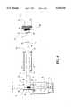
- FIG. 4is the schematic representation of the linear time of right mass spectrometer with orthogonal injection of externally generated ions, electrostatic deflector and tilted detector conversion surface.
- FIG. 5is the schematic representation of a Reflector TOF with parallel reflector and accelerator electrodes and fields.
- FIG. 6is the schematic representation of a Reflector-TOF MS with inclined reflector.
- FIG. 8shows the valuation of the distribution of arrival times induced by a spread in the orthogonal injection energy.
- Electrostatic deflectors with a homogeneous electrical field which is oriented perpendicular to the axis of a charged particle beamare used to steer or deflect this beam of ions or electrons into a desired direction.
- the ions deflection trajectoriesare independent of the particles mass to charge ratio and depend only on electric potentials. This feature makes it especially suitable for TOF-MS in that all ions can be accelerated and deflected by the same electric potential difference.
- electrostatic deflectorsconsist of two parallel plate electrodes 11 and 12 spaced an equal distance apart with the beam of charged particles 13 entering at the symmetry plane between the deflector plates.
- One plateis held at a positive electrical potential while the other is held at a negative electrical potential with respect to the last electrode, aperture or shielding tube 14 that was passed by the ion beam prior to entering the deflector.
- This reference potentialwill be referred to as the beam potential.
- the electric field between the platesaccelerates the charged particles perpendicular to the direction of the incoming beam 13 and therefore changes the direction of the beam.
- the applied deflection voltage Vis split symmetrically with respect to the beam potential for the sake of simplicity. Then, in the symmetry plane between the plates 11 and 12 of a deflector, the potential inside the deflector is equal to the beam potential; the trajectory of ions 13 that enter the deflector in said symmetry plane is the reference trajectory. Ions enter the deflecting field with kinetic energy qU 0 , where q is the ion's electrical charge, and U 0 the total ion acceleration electric potential difference.
- the effects of the fringing fields at the ends of the platesare of minor concern as the ions spend much more time in the homogeneous field between the plates than in the inhomogeneous fields near the entry and exit of the deflector. It is known from Herzog that with special apertures close to the ends of the deflector plates the electric field in a close approximation acts as an ideal deflection field with instantaneous onset of a homogeneous perpendicular field at an effective field boundary which is determined only by the geometry of apertures and deflector plates.
- Ions moving above or below the reference trajectoryare decelerated (or accelerated) by entering the deflecting field; accordingly, they spend more (or less) time in the deflecting field than the central reference trajectory of the beam. This difference in residence times is of primary interest for TOF-MS.
- FIG. 1btwo coordinate system (x,y,z) and (x',y',z') are introduced in FIG. 1b; the z-axis of the unprimed coordinate system lies in the symmetry plane between the plates, the x-axis is perpendicular to the deflector plates 11 and 12.
- the axis of the primed systemare parallel to the unprimed ones, but the origin of the primed coordinate system moves with the reference trajectory.
- the difference ⁇ in residence time with respect to the reference trajectoryis given by: ##EQU5##
- T R (x)is the residence time as a function of the entry coordinate x.
- Vx/U 0 dis small compared to 1 and to first order, ⁇ 1 , the residence time difference, is given as a function of entry coordinate x by the relation: ##EQU6##
- the first order the time shift ⁇ 1is a linear function of x or x'.
- the isochronous surface ⁇ 1 (x')is a plane tilted by an angle ⁇ with respect to the x'-y' (parallel to the x-y) plane (FIG. 2): ##EQU8##
- Equation (8)contains the primary discovery underlying the invention: A package of ions 21 that is isochronous in the x-y plane entering an electrostatic deflector along the z-axis and that is deflected by a certain small angle in the x-z plane is tilted in space with respect to the x-y plane by that same angle but in the opposite sense of rotation (FIG. 3a).
- the detector surfaceis mounted perpendicular to the axis of the instrument, i.e. it lies in the x'-y' plane.
- w 0be the width of the undeflected package in z'-direction and b its width in the x-direction determined either by beam limiting apertures or by the open width of the detector itself. Then, the apparent width of the package as it is seen by the detector surface is;
- the inventiontherefore states that, in order to achieve the optimum mass resolution in a linear TOF-MS instrument that uses electrostatic deflectors, the detector surface has to be tilted with respect to the instrument axis in the plane of deflection by an angle equal to the angle of deflection but in the opposite sense of rotation.
- Misalignment between the isochronous ion package surface and the detector surfacemay also be caused by mechanical tolerances of the vacuum chambers or mounting fixtures, by the bending of chambers or flanges when under the force of outside atmospheric pressure or by other mechanical distortions. It is known in the field of TOF-MS that in order to correct the alignment of the two planes and optimize the performance of a TOF-MS instrument, adjustable detector mounts may be used. It is the new feature of this invention to relate the bias angle of the detector surface directly to the angle of deflection in an instrument that employs electrostatic deflectors.
- a linear TOF-MSis shown schematically in FIG. 4, comprising an ion accelerator with two stages 26 and 27, a drift space 28, and an ion detector 40 with detector surface 34.
- the first stage accelerator 26is formed by repeller electrodes 21 and 22 and the second stage accelerator 27 is formed by the electrodes 22 and 23. These electrodes are essentially flat and mounted parallel to each other and perpendicular to the instrument axis 24. Central openings in electrodes 22 and 23 are covered with meshes 29 and 30 to assure homogenous electric fields in spaces 26 and 27 when electrical potentials are applied to electrodes 21, 22, and 23. It is taught in U.S. Pat. No.
- linear TOF-MSmay comprise additional electrodes, shields, apertures, etc., to suffice for specific needs.
- a continuous beam of ions 41is at first generated externally to the actual TOF-MS by means of an ion source 10 and accelerating, focusing, and steering electrodes, which comprise an ion transfer system 20.
- This transfer systemmay guide the ions through one or more stages of differential pumping and may include means to effectively assimilate the motion of all ions in said beam, preferentially in a high pressure radio-frequency-ion-guide.
- said ions 41When exiting from the transfer system 20 said ions 41 shall have a mean kinetic energy qU i , where q is the ion charge and U i is a total accelerating electrical potential difference.
- This initial beam of ionsis directed into the gap 26 between the first two electrodes 21 and 22 of the ion accelerator of the linear TOF-MS. It was found to be advantageous (O'Halloran et al.), if the injection is done in such a way that the direction of motion of the initial ion beam 41 is parallel to the accelerator electrodes 21 and 22, hence orthogonal to the instrument axis 24.
- Ionsare admitted into the space between electrodes 21 and 22, while those are held at a common electrical potential equal to the electric potential of the last electrode used to form the initial ion beam, which in turn is preferentially held at ground potential.
- first stage accelerator 26may be effectively divided by an additional electrode, the purpose of that electrode being to shield the space where the ions from the initial beam enter the accelerator from the electrical field which penetrates into space 26 from space 27 through the mesh 29.
- additional electrodes held at electrical potentials intermediate to the potentials applied to either electrodes 21 and 22 or 22 and 23, and proportional to their distance from those electrodesmay be used to extend the length of each accelerator stage.
- the electrical potentials applied to the accelerator electrodes 21 and 22can be reset to their original values, so that new ions from the initial beam 41 can enter into the space between them and a new cycle may begin.
- the ionsAfter passing through the accelerating stages 26 and 27 of the TOF-MS, the ions reach the field free drift space 28. Due to the initial perpendicular motion, the drift direction is oblique to the axis of the accelerator fields and the instrument axis 24. The magnitude of the obliqueness depends only on the relative energies of the ions when they enter the region 26 and the field free drift region 28.
- the drift angle ⁇is of the order of several degrees.
- an electrostatic deflectorwith plate electrodes 11 and 12 and entrance and exit apertures 14 is employed in the preferred embodiment.
- the electrostatic deflectorthus serves as a steering lens for steering the ion beam.
- the gap between the plates 11 and 12is chosen but not restricted to be at least twice as wide as the width of the ion beam, and the length of the plates is chosen to be at least twice as long as the gap.
- the width of the platesis chosen accordingly to the width of the ion beam in that direction, but at least 1.5 times the width of the gap.
- the ionswill drift parallel to the instrument axis 24 when leaving the deflector and reach the ion detector 40 at the end of the drift space 28.
- the isochronous surface of an ion packetis tilted. This is shown in FIG. 3B and is indicated in FIG. 4 by isochronous surfaces s 1 and s 2 .
- the ion detector surface 34is tilted with respect to a plane perpendicular to the instrument axis 24, the tilt angle lying in the plane of deflection and being equal to the angle of deflection but in the opposite sense of rotation. From Equation (11) the initial drift angle can be calculated.
- the required deflection angleis known, as well as the mounting angle of the detector surface and the voltage required to achieve such a deflection for a given deflector geometry.
- the alignment of said detector surfaceis preset by means of an angular spacer or fixture 35.
- the mounting of the detectoris made adjustable by means of one or two adjusters 36, adjusting the tilting in the plane of deflection, and the inclination in the perpendicular plane.
- the adjusters 36are made in such a way as to allow one to align the surface of the detector while operating the TOF-MS.
- the predetermined tilt angleis preset by means of the adjuster or adjusters 36 according to the relations which specify the tilt angle of the isochronous surface of the ion packages.
- FIG. 5The V-shaped geometry of a Reflector-TOF-MS is schematically shown in FIG. 5, the embodiment comprising a single stage accelerator formed by electrodes 51 and 52, a deflector 53, an ion reflector 54 with homogeneous fields, the reflector having one or more stages, and a detector with detector surface 55.
- the isochronous surfaceis tilted by the angle of deflection which is indicated in the FIG. 5 by isochronous surfaces s 1 , and s 2 .
- isochronous surfaces s 1 , and s 2By following the trajectories 56 and 57 from surfaces s 2 to s 3 through the reflection of the ion package it becomes evident that the angle of inclination with respect to the plane normal to the reflector axis 58 changes its sign.
- the detector surface 55must be inclined with respect to the instrument axis 24 in the plane of deflection, by the angle of deflection and in the direction of rotation of the deflection.
- this anglemay be preset by angular spacers, or preset by adjusters, and may be adjustable around that preset value. Furthermore, by means of multiple, preferentially mutually orthogonal deflectors, a multiple deflection may be facilitated, which, according to the invention, will require a compound angle of the detector surface.
- FIG. 6It includes the same accelerator, deflector, and reflector as FIG. 5, the deflection angle being ⁇ 0 .
- the reflector axis 59is inclined with respect to the instrument axis 24, the inclination being in the plane of deflection, and by the angle of deflection.
- the reflector surface 61becomes parallel with the isochronous surface s 2 of the ion packages, which themselves are tilted due to the deflection by the electrostatic deflector 53.
- the isochronous surface s 3remains parallel to the reflector surface 61, indicated by parallel planes p 1 , P 2 , p 3 , and p 4 .
- the detector surface 65is mounted parallel to the reflector surface 61, by the means as they were already described above.
- Equation (1)is the first order shift in time as calculated above (Equ. 4) and ⁇ 2 is the second order shift; ⁇ 2 gives only positive contributions; ions with x ⁇ 0 arrive later than is expected from the first order approximation.
- the isochronous surfaceis curved: ##EQU12##
- w 2is small. With big area detectors, however, w 2 limits the mass resolution of a TOF instrument. In this case, the inverse dependency of w 2 from the plate length l indicates that it is advantageous to utilize rather long deflectors.
- Ions with energy U 0are deflected by an angle ⁇ 0 and form the isochronous plane P inclined by the angle ⁇ 0 according to the first order result.
- any ion with qU i1 ⁇ qU i0will initially travel under the angle ⁇ 1 ⁇ 0 and will leave the deflector at an angle ⁇ 1 - ⁇ 0 ⁇ 0. In order to arrive at F, this ion would have to start at a different location X 1 (x 1 ,0,0) with x 1 >x 0 . Inside the deflector this ion follows a trajectory that is more in the "slower" section. Similarly, an ion with initial orthogonal energy qU i2 >qU i0 will travel through the deflector in the "faster" section.
- the orthogonal injection energycan be written as:
- Electrostatic lensesare used to focus the ions on the detector of the TOF-MS in order to improve the sensitivity of the instrument.
Landscapes
- Chemical & Material Sciences (AREA)
- Analytical Chemistry (AREA)
- Electron Tubes For Measurement (AREA)
Abstract
Description
w=w.sub.0 +w.sub.1 ; w.sub.1 =b·α.sub.0 (9)
w.sub.1 =b·(α-γ) (10)
∂α=α-α.sub.0 =-δ·α.sub.0(18)
w.sub.4 ≈L·∂α·α.sub.0 =δ·L·α.sub.0.sup.2 (19)
qU.sub.i =q·(1+ε)·U.sub.i,0 (21)
______________________________________ 2,685,035 July 27, 1954 Wiley 4,072,862 Feb. 7, 1978 Mamyrin et al. ______________________________________
______________________________________ 198,034 Soviet Union (Mamyrin Russian Patent, filed 1966) ______________________________________
Claims (13)
Priority Applications (9)
| Application Number | Priority Date | Filing Date | Title |
|---|---|---|---|
| US08/694,878US5654544A (en) | 1995-08-10 | 1996-08-09 | Mass resolution by angular alignment of the ion detector conversion surface in time-of-flight mass spectrometers with electrostatic steering deflectors |
| US08/880,060US5847385A (en) | 1996-08-09 | 1997-06-20 | Mass resolution by angular alignment of the ion detector conversion surface in time-of-flight mass spectrometers with electrostatic steering deflectors |
| PCT/US1997/013625WO1998007176A1 (en) | 1996-08-09 | 1997-08-04 | An angular alignment of the ion detector surface in time-of-flight mass spectrometers |
| CA002262615ACA2262615C (en) | 1996-08-09 | 1997-08-11 | An angular alignement of the ion detector surface in time-of-flight mass spectrometers |
| DE69733477TDE69733477T2 (en) | 1996-08-09 | 1997-08-11 | ANGLE POSITIONING OF THE DETECTOR SURFACE IN A FLY TIME MASS SPECTROMETER |
| AU39143/97AAU3914397A (en) | 1996-08-09 | 1997-08-11 | An angular alignement of the ion detector surface in time-of-flight mass spectrometers |
| JP50997098AJP2001523378A (en) | 1996-08-09 | 1997-08-11 | Angled array of ion detectors in a time-of-flight mass spectrometer |
| PCT/US1997/014195WO1998007179A1 (en) | 1996-08-09 | 1997-08-11 | An angular alignement of the ion detector surface in time-of-flight mass spectrometers |
| EP97936486AEP0917727B1 (en) | 1996-08-09 | 1997-08-11 | An angular alignement of the ion detector surface in time-of-flight mass spectrometers |
Applications Claiming Priority (2)
| Application Number | Priority Date | Filing Date | Title |
|---|---|---|---|
| US212195P | 1995-08-10 | 1995-08-10 | |
| US08/694,878US5654544A (en) | 1995-08-10 | 1996-08-09 | Mass resolution by angular alignment of the ion detector conversion surface in time-of-flight mass spectrometers with electrostatic steering deflectors |
Related Child Applications (1)
| Application Number | Title | Priority Date | Filing Date |
|---|---|---|---|
| US08/880,060ContinuationUS5847385A (en) | 1996-08-09 | 1997-06-20 | Mass resolution by angular alignment of the ion detector conversion surface in time-of-flight mass spectrometers with electrostatic steering deflectors |
Publications (1)
| Publication Number | Publication Date |
|---|---|
| US5654544Atrue US5654544A (en) | 1997-08-05 |
Family
ID=26669972
Family Applications (1)
| Application Number | Title | Priority Date | Filing Date |
|---|---|---|---|
| US08/694,878Expired - LifetimeUS5654544A (en) | 1995-08-10 | 1996-08-09 | Mass resolution by angular alignment of the ion detector conversion surface in time-of-flight mass spectrometers with electrostatic steering deflectors |
Country Status (1)
| Country | Link |
|---|---|
| US (1) | US5654544A (en) |
Cited By (72)
| Publication number | Priority date | Publication date | Assignee | Title |
|---|---|---|---|---|
| WO1998000224A1 (en)* | 1996-07-03 | 1998-01-08 | Analytica Of Branford, Inc. | A time-of-flight mass spectrometer with first and second order longitudinal focusing |
| WO1998007178A1 (en)* | 1996-08-09 | 1998-02-19 | Analytica Of Branford, Inc. | Ion storage time-of-flight mass spectrometer |
| US5825025A (en)* | 1995-11-08 | 1998-10-20 | Comstock, Inc. | Miniaturized time-of-flight mass spectrometer |
| US5847385A (en)* | 1996-08-09 | 1998-12-08 | Analytica Of Branford, Inc. | Mass resolution by angular alignment of the ion detector conversion surface in time-of-flight mass spectrometers with electrostatic steering deflectors |
| US5898173A (en)* | 1996-09-03 | 1999-04-27 | Bruker Daltonik Gmbh | High resolution ion detection for linear time-of-flight mass spectrometers |
| US6057543A (en)* | 1995-05-19 | 2000-05-02 | Perseptive Biosystems, Inc. | Time-of-flight mass spectrometry analysis of biomolecules |
| US6369384B1 (en) | 1999-06-23 | 2002-04-09 | Agilent Technologies, Inc. | Time-of-flight mass spectrometer with post-deflector filter assembly |
| WO2002097403A1 (en) | 2001-05-25 | 2002-12-05 | Analytica Of Branford, Inc. | Multiple detection systems |
| US6495823B1 (en) | 1999-07-21 | 2002-12-17 | The Charles Stark Draper Laboratory, Inc. | Micromachined field asymmetric ion mobility filter and detection system |
| US20030052263A1 (en)* | 2001-06-30 | 2003-03-20 | Sionex Corporation | System for collection of data and identification of unknown ion species in an electric field |
| US20030070913A1 (en)* | 2001-08-08 | 2003-04-17 | Sionex Corporation | Capacitive discharge plasma ion source |
| US20030136903A1 (en)* | 2001-12-18 | 2003-07-24 | Bruker Daltonik Gmbh | Time-of-flight mass spectrometers with orthogonal ion injection |
| US6690004B2 (en) | 1999-07-21 | 2004-02-10 | The Charles Stark Draper Laboratory, Inc. | Method and apparatus for electrospray-augmented high field asymmetric ion mobility spectrometry |
| US20040079878A1 (en)* | 1995-05-19 | 2004-04-29 | Perseptive Biosystems, Inc. | Time-of-flight mass spectrometry analysis of biomolecules |
| US20040094703A1 (en)* | 2001-11-17 | 2004-05-20 | Bruker Daltonik Gmbh | Space-angle focusing reflector for time-of-flight mass spectrometers |
| US20040094704A1 (en)* | 2002-04-12 | 2004-05-20 | Sionex Corporation | Method and apparatus for control of mobility-based ion species identification |
| US20040136872A1 (en)* | 2002-10-12 | 2004-07-15 | Sionex Corporation | NOx monitor using differential mobility spectrometry |
| US6806463B2 (en) | 1999-07-21 | 2004-10-19 | The Charles Stark Draper Laboratory, Inc. | Micromachined field asymmetric ion mobility filter and detection system |
| US6815669B1 (en) | 1999-07-21 | 2004-11-09 | The Charles Stark Draper Laboratory, Inc. | Longitudinal field driven ion mobility filter and detection system |
| US6815668B2 (en) | 1999-07-21 | 2004-11-09 | The Charles Stark Draper Laboratory, Inc. | Method and apparatus for chromatography-high field asymmetric waveform ion mobility spectrometry |
| US6815689B1 (en) | 2001-12-12 | 2004-11-09 | Southwest Research Institute | Mass spectrometry with enhanced particle flux range |
| US20040232325A1 (en)* | 2001-08-14 | 2004-11-25 | Sionex Corporation | Pancake spectrometer |
| US20050029449A1 (en)* | 1999-07-21 | 2005-02-10 | Miller Raanan A. | System for trajectory-based ion species identification |
| US20050040330A1 (en)* | 2001-06-30 | 2005-02-24 | Kaufman Lawrence A. | System for DMS peak resolution |
| US20050051719A1 (en)* | 1999-07-21 | 2005-03-10 | Sionex Corporation | Systems for differential ion mobility analysis |
| US20050056780A1 (en)* | 2003-09-17 | 2005-03-17 | Sionex Corporation | Solid-state gas flow generator and related systems, applications, and methods |
| US20050133716A1 (en)* | 1999-07-21 | 2005-06-23 | Miller Raanan A. | Explosives detection using differential ion mobility spectrometry |
| US20050139762A1 (en)* | 2003-11-25 | 2005-06-30 | Sionex Corporation | Mobility based apparatus and methods using dispersion characteristics, sample fragmentation, and/or pressure control to improve analysis of a sample |
| US20050167583A1 (en)* | 2003-12-18 | 2005-08-04 | Sionex Corporation | Methods and apparatus for enhanced ion based sample detection using selective pre-separation and amplification |
| US20050173629A1 (en)* | 2001-06-30 | 2005-08-11 | Miller Raanan A. | Methods and apparatus for enhanced sample identification based on combined analytical techniques |
| US20050230616A1 (en)* | 2004-02-02 | 2005-10-20 | Sionex Corporation | Compact sample analysis systems and related methods of using combined chromatography and mobility spectrometry techniques |
| US20050253061A1 (en)* | 2004-04-28 | 2005-11-17 | Sionex Corporation | Systems and methods for ion species analysis with enhanced condition control and data interpretation |
| US7091481B2 (en) | 2001-08-08 | 2006-08-15 | Sionex Corporation | Method and apparatus for plasma generation |
| US7098449B1 (en) | 1999-07-21 | 2006-08-29 | The Charles Stark Draper Laboratory, Inc. | Spectrometer chip assembly |
| US20060214100A1 (en)* | 2005-03-22 | 2006-09-28 | Leco Corporation | Multi-reflecting time-of-flight mass spectrometer with isochronous curved ion interface |
| US20060222562A1 (en)* | 2004-12-03 | 2006-10-05 | Sionex Corporation | Method and apparatus for enhanced ion based sample filtering and detection |
| US7122794B1 (en) | 2002-02-21 | 2006-10-17 | Sionex Corporation | Systems and methods for ion mobility control |
| US20070029477A1 (en)* | 2005-04-29 | 2007-02-08 | Sionex Corporation | Compact gas chromatography and ion mobility based sample analysis systems, methods, and devices |
| US20070272852A1 (en)* | 2006-01-26 | 2007-11-29 | Sionex Corporation | Differential mobility spectrometer analyzer and pre-filter apparatus, methods, and systems |
| US20080001080A1 (en)* | 2006-06-30 | 2008-01-03 | Wayne State University | Velocity Imaging Tandem Mass Spectrometer |
| US7399958B2 (en) | 1999-07-21 | 2008-07-15 | Sionex Corporation | Method and apparatus for enhanced ion mobility based sample analysis using various analyzer configurations |
| US7579589B2 (en) | 2005-07-26 | 2009-08-25 | Sionex Corporation | Ultra compact ion mobility based analyzer apparatus, method, and system |
| US20100072363A1 (en)* | 2006-12-11 | 2010-03-25 | Roger Giles | Co-axial time-of-flight mass spectrometer |
| US8217344B2 (en) | 2007-02-01 | 2012-07-10 | Dh Technologies Development Pte. Ltd. | Differential mobility spectrometer pre-filter assembly for a mass spectrometer |
| US20120175518A1 (en)* | 2011-01-10 | 2012-07-12 | Varian Semiconductor Equipment Associates, Inc. | Technique and apparatus for monitoring ion mass, energy, and angle in processing systems |
| WO2012123733A1 (en)* | 2011-03-15 | 2012-09-20 | Micromass Uk Limited | Electrostatic gimbal for correction of errors in time of flight mass spectrometers |
| DE102010062529A1 (en) | 2010-01-13 | 2013-07-18 | Agilent Technologies Inc. | Time-of-flight mass spectrometer with curved ion mirrors |
| US20140224979A1 (en)* | 2011-11-17 | 2014-08-14 | Canon Kabushiki Kaisha | Mass distribution spectrometry method and mass distribution spectrometer |
| US20140246575A1 (en)* | 2011-05-16 | 2014-09-04 | Micromass Uk Limited | Segmented Planar Calibration for Correction of Errors in Time of Flight Mass Spectrometers |
| US20170098533A1 (en)* | 2015-10-01 | 2017-04-06 | Shimadzu Corporation | Time of flight mass spectrometer |
| WO2019030477A1 (en)* | 2017-08-06 | 2019-02-14 | Anatoly Verenchikov | Accelerator for multi-pass mass spectrometers |
| US10593533B2 (en) | 2015-11-16 | 2020-03-17 | Micromass Uk Limited | Imaging mass spectrometer |
| US10629425B2 (en) | 2015-11-16 | 2020-04-21 | Micromass Uk Limited | Imaging mass spectrometer |
| US10636646B2 (en) | 2015-11-23 | 2020-04-28 | Micromass Uk Limited | Ion mirror and ion-optical lens for imaging |
| US10741376B2 (en) | 2015-04-30 | 2020-08-11 | Micromass Uk Limited | Multi-reflecting TOF mass spectrometer |
| US10950425B2 (en) | 2016-08-16 | 2021-03-16 | Micromass Uk Limited | Mass analyser having extended flight path |
| US11049712B2 (en) | 2017-08-06 | 2021-06-29 | Micromass Uk Limited | Fields for multi-reflecting TOF MS |
| US11081332B2 (en) | 2017-08-06 | 2021-08-03 | Micromass Uk Limited | Ion guide within pulsed converters |
| US11158494B2 (en)* | 2018-05-23 | 2021-10-26 | Thermo Fisher Scientific (Bremen) Gmbh | Ion front tilt correction for time of flight (TOF) mass spectrometer |
| US11205568B2 (en) | 2017-08-06 | 2021-12-21 | Micromass Uk Limited | Ion injection into multi-pass mass spectrometers |
| US11211238B2 (en) | 2017-08-06 | 2021-12-28 | Micromass Uk Limited | Multi-pass mass spectrometer |
| US11239067B2 (en) | 2017-08-06 | 2022-02-01 | Micromass Uk Limited | Ion mirror for multi-reflecting mass spectrometers |
| US11295944B2 (en) | 2017-08-06 | 2022-04-05 | Micromass Uk Limited | Printed circuit ion mirror with compensation |
| US11309175B2 (en) | 2017-05-05 | 2022-04-19 | Micromass Uk Limited | Multi-reflecting time-of-flight mass spectrometers |
| US11328920B2 (en) | 2017-05-26 | 2022-05-10 | Micromass Uk Limited | Time of flight mass analyser with spatial focussing |
| US11342175B2 (en) | 2018-05-10 | 2022-05-24 | Micromass Uk Limited | Multi-reflecting time of flight mass analyser |
| US11367608B2 (en) | 2018-04-20 | 2022-06-21 | Micromass Uk Limited | Gridless ion mirrors with smooth fields |
| US11587779B2 (en) | 2018-06-28 | 2023-02-21 | Micromass Uk Limited | Multi-pass mass spectrometer with high duty cycle |
| US11621156B2 (en) | 2018-05-10 | 2023-04-04 | Micromass Uk Limited | Multi-reflecting time of flight mass analyser |
| US11848185B2 (en) | 2019-02-01 | 2023-12-19 | Micromass Uk Limited | Electrode assembly for mass spectrometer |
| US11881387B2 (en) | 2018-05-24 | 2024-01-23 | Micromass Uk Limited | TOF MS detection system with improved dynamic range |
| US12205813B2 (en) | 2019-03-20 | 2025-01-21 | Micromass Uk Limited | Multiplexed time of flight mass spectrometer |
Citations (3)
| Publication number | Priority date | Publication date | Assignee | Title |
|---|---|---|---|---|
| US2642535A (en)* | 1946-10-18 | 1953-06-16 | Rca Corp | Mass spectrometer |
| US2938116A (en)* | 1956-04-02 | 1960-05-24 | Vard Products Inc | Molecular mass spectrometer |
| US4517462A (en)* | 1981-10-21 | 1985-05-14 | Commissariat A L'energie Atomique | Device for measuring an ion current produced by an ion beam |
- 1996
- 1996-08-09USUS08/694,878patent/US5654544A/ennot_activeExpired - Lifetime
Patent Citations (3)
| Publication number | Priority date | Publication date | Assignee | Title |
|---|---|---|---|---|
| US2642535A (en)* | 1946-10-18 | 1953-06-16 | Rca Corp | Mass spectrometer |
| US2938116A (en)* | 1956-04-02 | 1960-05-24 | Vard Products Inc | Molecular mass spectrometer |
| US4517462A (en)* | 1981-10-21 | 1985-05-14 | Commissariat A L'energie Atomique | Device for measuring an ion current produced by an ion beam |
Cited By (157)
| Publication number | Priority date | Publication date | Assignee | Title |
|---|---|---|---|---|
| US20040079878A1 (en)* | 1995-05-19 | 2004-04-29 | Perseptive Biosystems, Inc. | Time-of-flight mass spectrometry analysis of biomolecules |
| US6057543A (en)* | 1995-05-19 | 2000-05-02 | Perseptive Biosystems, Inc. | Time-of-flight mass spectrometry analysis of biomolecules |
| US6281493B1 (en) | 1995-05-19 | 2001-08-28 | Perseptive Biosystems, Inc. | Time-of-flight mass spectrometry analysis of biomolecules |
| US5825025A (en)* | 1995-11-08 | 1998-10-20 | Comstock, Inc. | Miniaturized time-of-flight mass spectrometer |
| WO1998000224A1 (en)* | 1996-07-03 | 1998-01-08 | Analytica Of Branford, Inc. | A time-of-flight mass spectrometer with first and second order longitudinal focusing |
| WO1998007178A1 (en)* | 1996-08-09 | 1998-02-19 | Analytica Of Branford, Inc. | Ion storage time-of-flight mass spectrometer |
| US5847385A (en)* | 1996-08-09 | 1998-12-08 | Analytica Of Branford, Inc. | Mass resolution by angular alignment of the ion detector conversion surface in time-of-flight mass spectrometers with electrostatic steering deflectors |
| US5898173A (en)* | 1996-09-03 | 1999-04-27 | Bruker Daltonik Gmbh | High resolution ion detection for linear time-of-flight mass spectrometers |
| US6369384B1 (en) | 1999-06-23 | 2002-04-09 | Agilent Technologies, Inc. | Time-of-flight mass spectrometer with post-deflector filter assembly |
| US20050133716A1 (en)* | 1999-07-21 | 2005-06-23 | Miller Raanan A. | Explosives detection using differential ion mobility spectrometry |
| US20080128612A1 (en)* | 1999-07-21 | 2008-06-05 | The Charles Stark Draper Laboratory, Inc. | Method and apparatus for chromatography high field asymmetric waveform ion mobility spectrometry |
| US7262407B2 (en) | 1999-07-21 | 2007-08-28 | Sionex Corporation | Explosives detection using differential mobility spectrometry |
| US7435950B2 (en) | 1999-07-21 | 2008-10-14 | The Charles Stark Draper Laboratory, Inc. | Micromachined field asymmetric ion mobility filter and detection system |
| US6690004B2 (en) | 1999-07-21 | 2004-02-10 | The Charles Stark Draper Laboratory, Inc. | Method and apparatus for electrospray-augmented high field asymmetric ion mobility spectrometry |
| US6495823B1 (en) | 1999-07-21 | 2002-12-17 | The Charles Stark Draper Laboratory, Inc. | Micromachined field asymmetric ion mobility filter and detection system |
| US20080224032A1 (en)* | 1999-07-21 | 2008-09-18 | Sionex Corporation | Micromachined field asymmetric ion mobility filter and detection system |
| US20080185512A1 (en)* | 1999-07-21 | 2008-08-07 | Sionex Corporation | Method and apparatus for enhanced ion mobility based sample analysis using various analyzer configurations |
| US7456390B2 (en) | 1999-07-21 | 2008-11-25 | The Charles Stark Draper Laboratory, Inc. | Longitudinal field driven ion mobility filter and detection system |
| US20040124350A1 (en)* | 1999-07-21 | 2004-07-01 | The Charles Stark Draper Laboratory, Inc. | Method and apparatus for electrospray augmented high field asymmetric ion mobility spectrometry |
| US7399958B2 (en) | 1999-07-21 | 2008-07-15 | Sionex Corporation | Method and apparatus for enhanced ion mobility based sample analysis using various analyzer configurations |
| US6806463B2 (en) | 1999-07-21 | 2004-10-19 | The Charles Stark Draper Laboratory, Inc. | Micromachined field asymmetric ion mobility filter and detection system |
| US6815669B1 (en) | 1999-07-21 | 2004-11-09 | The Charles Stark Draper Laboratory, Inc. | Longitudinal field driven ion mobility filter and detection system |
| US6815668B2 (en) | 1999-07-21 | 2004-11-09 | The Charles Stark Draper Laboratory, Inc. | Method and apparatus for chromatography-high field asymmetric waveform ion mobility spectrometry |
| US20080135745A1 (en)* | 1999-07-21 | 2008-06-12 | Sionex Corporation | Explosives detection using differential mobility spectrometry |
| US20080128609A1 (en)* | 1999-07-21 | 2008-06-05 | Sionex Corporation | Systems for differential ion mobility analysis |
| US20040240843A1 (en)* | 1999-07-21 | 2004-12-02 | The Charles Stark Draper Laboratory, Inc. | Longitudinal field driven ion mobility filter and detection system |
| US20050017163A1 (en)* | 1999-07-21 | 2005-01-27 | The Charles Stark Draper Laboratory, Inc. | Method and apparatus for chromatography-high field asymmetric waveform ion mobility spectrometry |
| US20050023457A1 (en)* | 1999-07-21 | 2005-02-03 | The Charles Stark Draper Laboratory, Inc. | Micromachined field asymmetric ion mobility filter and detection system |
| US20050029449A1 (en)* | 1999-07-21 | 2005-02-10 | Miller Raanan A. | System for trajectory-based ion species identification |
| US20050029443A1 (en)* | 1999-07-21 | 2005-02-10 | The Charles Stark Draper Laboratory, Inc. | Method and apparatus for chromatography-high field asymmetric waveform ion mobility spectrometry |
| US7211791B2 (en) | 1999-07-21 | 2007-05-01 | The Charles Stark Draper Laboratory, Inc. | Method and apparatus for chromatography-high field asymmetric waveform ion mobility spectrometry |
| US20050051719A1 (en)* | 1999-07-21 | 2005-03-10 | Sionex Corporation | Systems for differential ion mobility analysis |
| US7619214B2 (en) | 1999-07-21 | 2009-11-17 | The Charles Stark Draper Laboratory, Inc. | Spectrometer chip assembly |
| US7462825B2 (en) | 1999-07-21 | 2008-12-09 | The Charles Stark Draper Laboratory, Inc. | Method and apparatus for electrospray-augmented high field asymmetric ion mobility spectrometry |
| US7241989B2 (en) | 1999-07-21 | 2007-07-10 | Sionex Corp. | Systems for differential ion mobility analysis |
| US7365316B2 (en) | 1999-07-21 | 2008-04-29 | The Charles Stark Draper Laboratory | Method and apparatus for chromatography-high field asymmetric waveform ion mobility spectrometry |
| US20050145789A1 (en)* | 1999-07-21 | 2005-07-07 | The Charles Stark Draper Laboratory, Inc. | Method and apparatus for electrospray augmented high field asymmetric ion mobility spectrometry |
| US7355170B2 (en) | 1999-07-21 | 2008-04-08 | Sionex Corporation | Systems for differential ion mobility analysis |
| US20070084999A1 (en)* | 1999-07-21 | 2007-04-19 | The Charles Stark Draper Laboratory, Inc. | Method and apparatus for electrospray-augmented high field asymmetric ion mobility spectrometry |
| US7176453B2 (en) | 1999-07-21 | 2007-02-13 | The Charles Stark Draper Laboratory, Inc. | Method and apparatus for chromatography-high field asymmetric waveform ion mobility spectrometry |
| US8410432B2 (en) | 1999-07-21 | 2013-04-02 | Dh Technologies Development Pte. Ltd. | Method and apparatus for enhanced ion mobility based sample analysis using various analyzer configurations |
| US7605367B2 (en) | 1999-07-21 | 2009-10-20 | Sionex Corporation | Explosives detection using differential mobility spectrometry |
| US20050263699A1 (en)* | 1999-07-21 | 2005-12-01 | The Charles Stark Draper Laboratory, Inc. | Method and apparatus for electrospray augmented high field asymmetric ion mobility spectrometry |
| US6972407B2 (en) | 1999-07-21 | 2005-12-06 | The Charles Stark Draper Laboratory, Inc. | Method and apparatus for electrospray augmented high field asymmetric ion mobility spectrometry |
| US7547879B2 (en) | 1999-07-21 | 2009-06-16 | The Charles Stark Draper Laboratory, Inc. | Longitudinal field driven ion mobility filter and detection system |
| US7576319B2 (en) | 1999-07-21 | 2009-08-18 | Sionex Corporation | Systems for differential ion mobility analysis |
| US7030372B2 (en) | 1999-07-21 | 2006-04-18 | Sionex Corporation | Micromachined field asymmetric ion mobility filter and detection system |
| US7148477B2 (en) | 1999-07-21 | 2006-12-12 | Sionex Corporation | System for trajectory-based ion species identification |
| US7057168B2 (en) | 1999-07-21 | 2006-06-06 | Sionex Corporation | Systems for differential ion mobility analysis |
| US7075068B2 (en) | 1999-07-21 | 2006-07-11 | The Charles Stark Draper Laboratory, Inc. | Method and apparatus for electrospray augmented high field asymmetric ion mobility spectrometry |
| US20060151687A1 (en)* | 1999-07-21 | 2006-07-13 | Sionex Corporation | Systems for differential ion mobility analysis |
| US7129482B2 (en) | 1999-07-21 | 2006-10-31 | Sionex Corporation | Explosives detection using differential ion mobility spectrometry |
| US20070228269A1 (en)* | 1999-07-21 | 2007-10-04 | Sionex Corporation | Systems for differential ion mobility analysis |
| US7098449B1 (en) | 1999-07-21 | 2006-08-29 | The Charles Stark Draper Laboratory, Inc. | Spectrometer chip assembly |
| US20060192102A1 (en)* | 1999-07-21 | 2006-08-31 | The Charles Stark Draper Laboratory, Inc. | Longitudinal field driven ion mobility filter and detection system |
| WO2002097403A1 (en) | 2001-05-25 | 2002-12-05 | Analytica Of Branford, Inc. | Multiple detection systems |
| US7928361B1 (en) | 2001-05-25 | 2011-04-19 | Perkinelmer Health Sciences, Inc. | Multiple detection systems |
| US7714284B2 (en) | 2001-06-30 | 2010-05-11 | Sionex Corporation | Methods and apparatus for enhanced sample identification based on combined analytical techniques |
| US7119328B2 (en) | 2001-06-30 | 2006-10-10 | Sionex Corporation | System for DMS peak resolution |
| US7045776B2 (en) | 2001-06-30 | 2006-05-16 | Sionex Corporation | System for collection of data and identification of unknown ion species in an electric field |
| US20050173629A1 (en)* | 2001-06-30 | 2005-08-11 | Miller Raanan A. | Methods and apparatus for enhanced sample identification based on combined analytical techniques |
| US20030052263A1 (en)* | 2001-06-30 | 2003-03-20 | Sionex Corporation | System for collection of data and identification of unknown ion species in an electric field |
| US20050040330A1 (en)* | 2001-06-30 | 2005-02-24 | Kaufman Lawrence A. | System for DMS peak resolution |
| US7091481B2 (en) | 2001-08-08 | 2006-08-15 | Sionex Corporation | Method and apparatus for plasma generation |
| US20060237669A1 (en)* | 2001-08-08 | 2006-10-26 | Sionex Corporation | Method and apparatus for plasma generation |
| US7279680B2 (en) | 2001-08-08 | 2007-10-09 | Sionex Corporation | Method and apparatus for plasma generation |
| US7274015B2 (en) | 2001-08-08 | 2007-09-25 | Sionex Corporation | Capacitive discharge plasma ion source |
| US20030070913A1 (en)* | 2001-08-08 | 2003-04-17 | Sionex Corporation | Capacitive discharge plasma ion source |
| US20040232325A1 (en)* | 2001-08-14 | 2004-11-25 | Sionex Corporation | Pancake spectrometer |
| US7217920B2 (en) | 2001-08-14 | 2007-05-15 | Sionex Corporation | Pancake spectrometer |
| US20060169886A1 (en)* | 2001-08-14 | 2006-08-03 | Sionex Corporation | Pancake spectrometer |
| US20040094703A1 (en)* | 2001-11-17 | 2004-05-20 | Bruker Daltonik Gmbh | Space-angle focusing reflector for time-of-flight mass spectrometers |
| US6740872B1 (en)* | 2001-11-17 | 2004-05-25 | Brukder Daltonik Gmbh | Space-angle focusing reflector for time-of-flight mass spectrometers |
| US6815689B1 (en) | 2001-12-12 | 2004-11-09 | Southwest Research Institute | Mass spectrometry with enhanced particle flux range |
| DE10162267B4 (en)* | 2001-12-18 | 2007-05-31 | Bruker Daltonik Gmbh | Reflector for time-of-flight mass spectrometers with orthogonal ion injection |
| US20030136903A1 (en)* | 2001-12-18 | 2003-07-24 | Bruker Daltonik Gmbh | Time-of-flight mass spectrometers with orthogonal ion injection |
| US7223966B2 (en) | 2001-12-18 | 2007-05-29 | Bruker Daltonik, Gmbh | Time-of-flight mass spectrometers with orthogonal ion injection |
| US7122794B1 (en) | 2002-02-21 | 2006-10-17 | Sionex Corporation | Systems and methods for ion mobility control |
| US20080121794A1 (en)* | 2002-02-21 | 2008-05-29 | Sionex Corporation | Systems and methods for ion mobility control |
| US7598489B2 (en) | 2002-02-21 | 2009-10-06 | Sionex Corporation | Systems and methods for ion mobility control |
| US7339164B2 (en) | 2002-02-21 | 2008-03-04 | Sionex Corporation | Systems and methods for ion mobility control |
| US7005632B2 (en) | 2002-04-12 | 2006-02-28 | Sionex Corporation | Method and apparatus for control of mobility-based ion species identification |
| US20050156107A1 (en)* | 2002-04-12 | 2005-07-21 | Miller Raanan A. | Method and apparatus for control of mobility-based ion species identification |
| US7230238B2 (en) | 2002-04-12 | 2007-06-12 | Sionex Corporation | Method and apparatus for control of mobility-based ion species identification |
| US20040094704A1 (en)* | 2002-04-12 | 2004-05-20 | Sionex Corporation | Method and apparatus for control of mobility-based ion species identification |
| US20040136872A1 (en)* | 2002-10-12 | 2004-07-15 | Sionex Corporation | NOx monitor using differential mobility spectrometry |
| US7019291B2 (en) | 2002-10-12 | 2006-03-28 | Sionex Corporation | NOx monitor using differential mobility spectrometry |
| US20050092914A1 (en)* | 2002-10-12 | 2005-05-05 | Sionex Corporation | NOx monitor using differential mobility spectrometry |
| US20050056780A1 (en)* | 2003-09-17 | 2005-03-17 | Sionex Corporation | Solid-state gas flow generator and related systems, applications, and methods |
| US7453060B2 (en) | 2003-09-17 | 2008-11-18 | Sionex Corporation | Solid-state flow generator and related systems, applications, and methods |
| US20070187590A1 (en)* | 2003-09-17 | 2007-08-16 | Sionex Corporation | Solid-state flow generator and related systems, applications, and methods |
| US20090045331A1 (en)* | 2003-09-17 | 2009-02-19 | Sionex Corporation | Solid-state flow generator and related systems, applications, and methods |
| US7223970B2 (en) | 2003-09-17 | 2007-05-29 | Sionex Corporation | Solid-state gas flow generator and related systems, applications, and methods |
| US20070252082A1 (en)* | 2003-11-25 | 2007-11-01 | Sionex Corporation | Mobility based apparatus and methods using dispersion characteristics, sample fragmentation, and/or pressure control to improve analysis of a sample |
| US20050139762A1 (en)* | 2003-11-25 | 2005-06-30 | Sionex Corporation | Mobility based apparatus and methods using dispersion characteristics, sample fragmentation, and/or pressure control to improve analysis of a sample |
| US7227134B2 (en) | 2003-11-25 | 2007-06-05 | Sionex Corporation | Mobility based apparatus and methods using dispersion characteristics, sample fragmentation, and/or pressure control to improve analysis of a sample |
| US20050167583A1 (en)* | 2003-12-18 | 2005-08-04 | Sionex Corporation | Methods and apparatus for enhanced ion based sample detection using selective pre-separation and amplification |
| US20110042561A1 (en)* | 2003-12-18 | 2011-02-24 | Dh Technologies Development Pte. Ltd. | Methods and apparatus for enhanced ion based sample detection using selective pre-separation and amplificaton |
| US8592751B2 (en) | 2003-12-18 | 2013-11-26 | Dh Technologies Development Pte. Ltd. | Methods and apparatus for enhanced ion based sample detection using selective pre-separation and amplification |
| US7902498B2 (en) | 2003-12-18 | 2011-03-08 | Dh Technologies Development Pte. Ltd. | Methods and apparatus for enhanced ion based sample detection using selective pre-separation and amplification |
| US7456394B2 (en) | 2004-02-02 | 2008-11-25 | Sionex Corporation | Compact sample analysis systems and related methods of using combined chromatography and mobility spectrometry techniques |
| US20050230616A1 (en)* | 2004-02-02 | 2005-10-20 | Sionex Corporation | Compact sample analysis systems and related methods of using combined chromatography and mobility spectrometry techniques |
| US7381944B2 (en) | 2004-04-28 | 2008-06-03 | Sionex Corporation | Systems and methods for ion species analysis with enhanced condition control and data interpretation |
| US20050253061A1 (en)* | 2004-04-28 | 2005-11-17 | Sionex Corporation | Systems and methods for ion species analysis with enhanced condition control and data interpretation |
| US20060222562A1 (en)* | 2004-12-03 | 2006-10-05 | Sionex Corporation | Method and apparatus for enhanced ion based sample filtering and detection |
| US7399959B2 (en) | 2004-12-03 | 2008-07-15 | Sionex Corporation | Method and apparatus for enhanced ion based sample filtering and detection |
| WO2006102430A3 (en)* | 2005-03-22 | 2007-12-06 | Leco Corp | Multi-reflecting time-of-flight mass spectrometer with isochronous curved ion interface |
| US20060214100A1 (en)* | 2005-03-22 | 2006-09-28 | Leco Corporation | Multi-reflecting time-of-flight mass spectrometer with isochronous curved ion interface |
| US7326925B2 (en)* | 2005-03-22 | 2008-02-05 | Leco Corporation | Multi-reflecting time-of-flight mass spectrometer with isochronous curved ion interface |
| US7608818B2 (en) | 2005-04-29 | 2009-10-27 | Sionex Corporation | Compact gas chromatography and ion mobility based sample analysis systems, methods, and devices |
| US20070029477A1 (en)* | 2005-04-29 | 2007-02-08 | Sionex Corporation | Compact gas chromatography and ion mobility based sample analysis systems, methods, and devices |
| US7579589B2 (en) | 2005-07-26 | 2009-08-25 | Sionex Corporation | Ultra compact ion mobility based analyzer apparatus, method, and system |
| US20070272852A1 (en)* | 2006-01-26 | 2007-11-29 | Sionex Corporation | Differential mobility spectrometer analyzer and pre-filter apparatus, methods, and systems |
| US20080001080A1 (en)* | 2006-06-30 | 2008-01-03 | Wayne State University | Velocity Imaging Tandem Mass Spectrometer |
| US7534996B2 (en)* | 2006-06-30 | 2009-05-19 | Wayne State University | Velocity imaging tandem mass spectrometer |
| US20100072363A1 (en)* | 2006-12-11 | 2010-03-25 | Roger Giles | Co-axial time-of-flight mass spectrometer |
| US8952325B2 (en)* | 2006-12-11 | 2015-02-10 | Shimadzu Corporation | Co-axial time-of-flight mass spectrometer |
| US8217344B2 (en) | 2007-02-01 | 2012-07-10 | Dh Technologies Development Pte. Ltd. | Differential mobility spectrometer pre-filter assembly for a mass spectrometer |
| DE102010062529A1 (en) | 2010-01-13 | 2013-07-18 | Agilent Technologies Inc. | Time-of-flight mass spectrometer with curved ion mirrors |
| US20120175518A1 (en)* | 2011-01-10 | 2012-07-12 | Varian Semiconductor Equipment Associates, Inc. | Technique and apparatus for monitoring ion mass, energy, and angle in processing systems |
| US8698107B2 (en)* | 2011-01-10 | 2014-04-15 | Varian Semiconductor Equipment Associates, Inc. | Technique and apparatus for monitoring ion mass, energy, and angle in processing systems |
| WO2012123733A1 (en)* | 2011-03-15 | 2012-09-20 | Micromass Uk Limited | Electrostatic gimbal for correction of errors in time of flight mass spectrometers |
| US8921775B2 (en) | 2011-03-15 | 2014-12-30 | Micromass Uk Limited | Electrostatic gimbal for correction of errors in time of flight mass spectrometers |
| US9082598B2 (en)* | 2011-05-16 | 2015-07-14 | Micromass Uk Limited | Segmented planar calibration for correction of errors in time of flight mass spectrometers |
| US8872104B2 (en)* | 2011-05-16 | 2014-10-28 | Micromass Uk Limited | Segmented planar calibration for correction of errors in time of flight mass spectrometers |
| US20150021467A1 (en)* | 2011-05-16 | 2015-01-22 | Micromass Uk Limited | Segmented Planar Calibration for Correction of Errors in Time of Flight Mass Spectrometers |
| US20140246575A1 (en)* | 2011-05-16 | 2014-09-04 | Micromass Uk Limited | Segmented Planar Calibration for Correction of Errors in Time of Flight Mass Spectrometers |
| US9455129B2 (en) | 2011-05-16 | 2016-09-27 | Micromass Uk Limited | Segmented planar calibration for correction of errors in time of flight mass spectrometers |
| US20140224979A1 (en)* | 2011-11-17 | 2014-08-14 | Canon Kabushiki Kaisha | Mass distribution spectrometry method and mass distribution spectrometer |
| US9312116B2 (en)* | 2011-11-17 | 2016-04-12 | Canon Kabushiki Kaisha | Mass distribution spectrometry method and mass distribution spectrometer |
| US10741376B2 (en) | 2015-04-30 | 2020-08-11 | Micromass Uk Limited | Multi-reflecting TOF mass spectrometer |
| US20170098533A1 (en)* | 2015-10-01 | 2017-04-06 | Shimadzu Corporation | Time of flight mass spectrometer |
| GB2543036A (en)* | 2015-10-01 | 2017-04-12 | Shimadzu Corp | Time of flight mass spectrometer |
| US10269549B2 (en)* | 2015-10-01 | 2019-04-23 | Shimadzu Corporation | Time of flight mass spectrometer |
| US10593533B2 (en) | 2015-11-16 | 2020-03-17 | Micromass Uk Limited | Imaging mass spectrometer |
| US10629425B2 (en) | 2015-11-16 | 2020-04-21 | Micromass Uk Limited | Imaging mass spectrometer |
| US10636646B2 (en) | 2015-11-23 | 2020-04-28 | Micromass Uk Limited | Ion mirror and ion-optical lens for imaging |
| US10950425B2 (en) | 2016-08-16 | 2021-03-16 | Micromass Uk Limited | Mass analyser having extended flight path |
| US11309175B2 (en) | 2017-05-05 | 2022-04-19 | Micromass Uk Limited | Multi-reflecting time-of-flight mass spectrometers |
| US11328920B2 (en) | 2017-05-26 | 2022-05-10 | Micromass Uk Limited | Time of flight mass analyser with spatial focussing |
| US11081332B2 (en) | 2017-08-06 | 2021-08-03 | Micromass Uk Limited | Ion guide within pulsed converters |
| US11817303B2 (en) | 2017-08-06 | 2023-11-14 | Micromass Uk Limited | Accelerator for multi-pass mass spectrometers |
| US11205568B2 (en) | 2017-08-06 | 2021-12-21 | Micromass Uk Limited | Ion injection into multi-pass mass spectrometers |
| US11211238B2 (en) | 2017-08-06 | 2021-12-28 | Micromass Uk Limited | Multi-pass mass spectrometer |
| US11239067B2 (en) | 2017-08-06 | 2022-02-01 | Micromass Uk Limited | Ion mirror for multi-reflecting mass spectrometers |
| US11295944B2 (en) | 2017-08-06 | 2022-04-05 | Micromass Uk Limited | Printed circuit ion mirror with compensation |
| US11049712B2 (en) | 2017-08-06 | 2021-06-29 | Micromass Uk Limited | Fields for multi-reflecting TOF MS |
| WO2019030477A1 (en)* | 2017-08-06 | 2019-02-14 | Anatoly Verenchikov | Accelerator for multi-pass mass spectrometers |
| US11756782B2 (en) | 2017-08-06 | 2023-09-12 | Micromass Uk Limited | Ion mirror for multi-reflecting mass spectrometers |
| US11367608B2 (en) | 2018-04-20 | 2022-06-21 | Micromass Uk Limited | Gridless ion mirrors with smooth fields |
| US11621156B2 (en) | 2018-05-10 | 2023-04-04 | Micromass Uk Limited | Multi-reflecting time of flight mass analyser |
| US11342175B2 (en) | 2018-05-10 | 2022-05-24 | Micromass Uk Limited | Multi-reflecting time of flight mass analyser |
| US11158494B2 (en)* | 2018-05-23 | 2021-10-26 | Thermo Fisher Scientific (Bremen) Gmbh | Ion front tilt correction for time of flight (TOF) mass spectrometer |
| US11881387B2 (en) | 2018-05-24 | 2024-01-23 | Micromass Uk Limited | TOF MS detection system with improved dynamic range |
| US11587779B2 (en) | 2018-06-28 | 2023-02-21 | Micromass Uk Limited | Multi-pass mass spectrometer with high duty cycle |
| US11848185B2 (en) | 2019-02-01 | 2023-12-19 | Micromass Uk Limited | Electrode assembly for mass spectrometer |
| US12205813B2 (en) | 2019-03-20 | 2025-01-21 | Micromass Uk Limited | Multiplexed time of flight mass spectrometer |
Similar Documents
| Publication | Publication Date | Title |
|---|---|---|
| US5654544A (en) | Mass resolution by angular alignment of the ion detector conversion surface in time-of-flight mass spectrometers with electrostatic steering deflectors | |
| US5847385A (en) | Mass resolution by angular alignment of the ion detector conversion surface in time-of-flight mass spectrometers with electrostatic steering deflectors | |
| US6621073B1 (en) | Time-of-flight mass spectrometer with first and second order longitudinal focusing | |
| US7982184B2 (en) | Multi-reflecting time-of-flight mass analyser and a time-of-flight mass spectrometer including the mass analyser | |
| US5160840A (en) | Time-of-flight analyzer and method | |
| US10741376B2 (en) | Multi-reflecting TOF mass spectrometer | |
| US7709789B2 (en) | TOF mass spectrometry with correction for trajectory error | |
| US8921775B2 (en) | Electrostatic gimbal for correction of errors in time of flight mass spectrometers | |
| Myers et al. | An inductively coupled plasma-time-of-flight mass spectrometer for elemental analysis. Part I: Optimization and characteristics | |
| US6770870B2 (en) | Tandem time-of-flight mass spectrometer with delayed extraction and method for use | |
| US7326925B2 (en) | Multi-reflecting time-of-flight mass spectrometer with isochronous curved ion interface | |
| US7372021B2 (en) | Time-of-flight mass spectrometer combining fields non-linear in time and space | |
| GB2491305A (en) | A mass spectrometer arranged to analyze positive and negative ions | |
| WO2018033494A1 (en) | Mass analyser having extended flight path | |
| GB2274197A (en) | Time-of-flight mass spectrometer | |
| US20060138316A1 (en) | Time-of-flight mass spectrometer | |
| CA2262615C (en) | An angular alignement of the ion detector surface in time-of-flight mass spectrometers | |
| US5942758A (en) | Shielded lens | |
| CN115881508A (en) | Time-of-flight mass spectrometer with multiple reflections | |
| US9129790B2 (en) | Orthogonal acceleration TOF with ion guide mode | |
| WO2003103008A1 (en) | Time of flight mass specrometer combining fields non-linear in time and space |
Legal Events
| Date | Code | Title | Description |
|---|---|---|---|
| STCF | Information on status: patent grant | Free format text:PATENTED CASE | |
| AS | Assignment | Owner name:ANALYTICA OF BRANFORD, INC., CONNECTICUT Free format text:ASSIGNMENT OF ASSIGNORS INTEREST;ASSIGNOR:DRESCH, THOMAS;REEL/FRAME:009556/0364 Effective date:19981005 | |
| FEPP | Fee payment procedure | Free format text:PAYOR NUMBER ASSIGNED (ORIGINAL EVENT CODE: ASPN); ENTITY STATUS OF PATENT OWNER: LARGE ENTITY | |
| FPAY | Fee payment | Year of fee payment:4 | |
| FPAY | Fee payment | Year of fee payment:8 | |
| FPAY | Fee payment | Year of fee payment:12 | |
| AS | Assignment | Owner name:PERKINELMER HEALTH SCIENCES, INC.,MASSACHUSETTS Free format text:MERGER;ASSIGNOR:ANALYTICA OF BRANFORD, INC.;REEL/FRAME:023985/0513 Effective date:20090629 Owner name:PERKINELMER HEALTH SCIENCES, INC., MASSACHUSETTS Free format text:MERGER;ASSIGNOR:ANALYTICA OF BRANFORD, INC.;REEL/FRAME:023985/0513 Effective date:20090629 | |
| FEPP | Fee payment procedure | Free format text:PAT HOLDER NO LONGER CLAIMS SMALL ENTITY STATUS, ENTITY STATUS SET TO UNDISCOUNTED (ORIGINAL EVENT CODE: STOL); ENTITY STATUS OF PATENT OWNER: LARGE ENTITY |