US5653251A - Vacuum actuated sheath valve - Google Patents
Vacuum actuated sheath valveDownload PDFInfo
- Publication number
- US5653251A US5653251AUS08/398,771US39877195AUS5653251AUS 5653251 AUS5653251 AUS 5653251AUS 39877195 AUS39877195 AUS 39877195AUS 5653251 AUS5653251 AUS 5653251A
- Authority
- US
- United States
- Prior art keywords
- vacuum
- valve
- channel
- set forth
- outlet
- Prior art date
- Legal status (The legal status is an assumption and is not a legal conclusion. Google has not performed a legal analysis and makes no representation as to the accuracy of the status listed.)
- Expired - Fee Related
Links
Images


Classifications
- F—MECHANICAL ENGINEERING; LIGHTING; HEATING; WEAPONS; BLASTING
- F16—ENGINEERING ELEMENTS AND UNITS; GENERAL MEASURES FOR PRODUCING AND MAINTAINING EFFECTIVE FUNCTIONING OF MACHINES OR INSTALLATIONS; THERMAL INSULATION IN GENERAL
- F16K—VALVES; TAPS; COCKS; ACTUATING-FLOATS; DEVICES FOR VENTING OR AERATING
- F16K15/00—Check valves
- F16K15/14—Check valves with flexible valve members
- F16K15/144—Check valves with flexible valve members the closure elements being fixed along all or a part of their periphery
- Y—GENERAL TAGGING OF NEW TECHNOLOGICAL DEVELOPMENTS; GENERAL TAGGING OF CROSS-SECTIONAL TECHNOLOGIES SPANNING OVER SEVERAL SECTIONS OF THE IPC; TECHNICAL SUBJECTS COVERED BY FORMER USPC CROSS-REFERENCE ART COLLECTIONS [XRACs] AND DIGESTS
- Y10—TECHNICAL SUBJECTS COVERED BY FORMER USPC
- Y10S—TECHNICAL SUBJECTS COVERED BY FORMER USPC CROSS-REFERENCE ART COLLECTIONS [XRACs] AND DIGESTS
- Y10S137/00—Fluid handling
- Y10S137/907—Vacuum-actuated valves
- Y—GENERAL TAGGING OF NEW TECHNOLOGICAL DEVELOPMENTS; GENERAL TAGGING OF CROSS-SECTIONAL TECHNOLOGIES SPANNING OVER SEVERAL SECTIONS OF THE IPC; TECHNICAL SUBJECTS COVERED BY FORMER USPC CROSS-REFERENCE ART COLLECTIONS [XRACs] AND DIGESTS
- Y10—TECHNICAL SUBJECTS COVERED BY FORMER USPC
- Y10T—TECHNICAL SUBJECTS COVERED BY FORMER US CLASSIFICATION
- Y10T137/00—Fluid handling
- Y10T137/2496—Self-proportioning or correlating systems
- Y10T137/2559—Self-controlled branched flow systems
- Y10T137/2564—Plural inflows
- Y10T137/2572—One inflow supplements another
- Y—GENERAL TAGGING OF NEW TECHNOLOGICAL DEVELOPMENTS; GENERAL TAGGING OF CROSS-SECTIONAL TECHNOLOGIES SPANNING OVER SEVERAL SECTIONS OF THE IPC; TECHNICAL SUBJECTS COVERED BY FORMER USPC CROSS-REFERENCE ART COLLECTIONS [XRACs] AND DIGESTS
- Y10—TECHNICAL SUBJECTS COVERED BY FORMER USPC
- Y10T—TECHNICAL SUBJECTS COVERED BY FORMER US CLASSIFICATION
- Y10T137/00—Fluid handling
- Y10T137/7722—Line condition change responsive valves
- Y10T137/7781—With separate connected fluid reactor surface
- Y10T137/7835—Valve seating in direction of flow
- Y10T137/7836—Flexible diaphragm or bellows reactor
- Y—GENERAL TAGGING OF NEW TECHNOLOGICAL DEVELOPMENTS; GENERAL TAGGING OF CROSS-SECTIONAL TECHNOLOGIES SPANNING OVER SEVERAL SECTIONS OF THE IPC; TECHNICAL SUBJECTS COVERED BY FORMER USPC CROSS-REFERENCE ART COLLECTIONS [XRACs] AND DIGESTS
- Y10—TECHNICAL SUBJECTS COVERED BY FORMER USPC
- Y10T—TECHNICAL SUBJECTS COVERED BY FORMER US CLASSIFICATION
- Y10T137/00—Fluid handling
- Y10T137/8593—Systems
- Y10T137/87571—Multiple inlet with single outlet
- Y10T137/87587—Combining by aspiration
- Y10T137/87643—With condition responsive valve
Definitions
- This inventionrelates to sheath valves, i.e., valves which permit the flow of liquid in only one direction.
- sheath valvesi.e., valves which permit the flow of liquid in only one direction.
- sheath valvewhich preferably uses a tensioned linear sheath, rather than a cylindrical sheath and to a sheath valve which is vacuum actuated.
- a sheath valveis a type of one-way valve which permits a liquid, gas, or other flowable material to be dispensed, but does not permit anything to pass backwards through the valve, and so prevents possible contamination to the contents remaining in the dispensing container.
- One form of one-way valveis a cylindrical core encompassed by an elastic cylindrical sheath, with the core having an entrance tube therein leading to a portion of the sheath, and an exit tube leading from the sheath.
- the two tubesare closed by the sheath and do not interconnect; but pressure applied to the liquid being dispensed serves to expand the sheath so that the liquid can pass from the entrance tube to the exit tube. Upon release of the pressure, the sheath contracts, sealing the valve against any possible reverse contamination.
- My one-way, vacuum actuated sheath valveuses inexpensive flat, elastic sheath material held in tension over a convex surface, that is, a surface which is wholly or partly curved or distended along at least one axis of a valve platform, which surface I refer to as a valve platform having a convex surface.
- a convex surfacethat is, a surface which is wholly or partly curved or distended along at least one axis of a valve platform, which surface I refer to as a valve platform having a convex surface.
- the valvecan control flow of various types of flowable products, such as liquids, pastes, and gases, referred to herein as "liquids.”
- the various embodimentsinclude as elements (a) a valve platform with a convex surface; (b) a sheath which can be a flat elastic sheet prepared from roll stock, a preformed injection, or compression molded component; (c) a housing component or cover for sheath protection and retention, the cover and valve platform being sealed together; and (d) a source of vacuum, such as a vacuum pump or a Venturi aspirator.
- valve platformthat is the functional area in terms of barrier and closure, the sheath being in tension over the surface of the sheath where it interfaces with the valve platform.
- This platformcan take a variety of shapes, ranging from a dome to a section of an elongated cylinder. The key consideration is the natural lay and stretch of the sheath when placed in tension, and its tight contact and interface with the valve platform.
- Second,is the number and configuration of entrance and exit ports and channels that function to channel liquid flow within the context of the valve.
- anchor mechanismscan take various forms, but each uses a cover piece which sandwiches the edges of the sheath between the platform and the cover piece; and each provides for spacing between the cover piece and the platform in the area where the ports interface with the sheath, i.e., an expansion chamber, so that the sheath can expand under pressure to permit fluid flow between the ports.
- a source of vacuumis a source of vacuum. It can be of any desired type, such as a vacuum pump or a Venturi. It is connected to the exit port and to a vacuum channel leading to the expansion chamber.
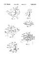
- FIG. 1is a perspective view of a dispenser of the type which might use the vacuum actuated sheath valve of this invention.
- the receiving container and source of vacuumare omitted from this view.
- FIG. 2is a partial section, taken on line 2--2 of FIG. 1, showing how the valve can be used in a dispenser.
- FIG. 3is an enlarged view of the circled area 3 of FIG. 2, used to better show the operation of the valve. It differs from FIG. 2, however, in that in FIG. 3 vacuum has been applied and fluid or paste is being drawn through the valve.
- FIG. 4is an exploded perspective view of the vacuum actuated sheath valve of my invention. A receiving container and a source of vacuum have been added to the sheath valve shown in FIG. 1.
- FIG. 5is a top plan view of the valve platform shown in FIG. 4.
- FIG. 6is an elevation, taken on line 6--6 of FIG. 5.
- FIG. 7is a section, taken on line 7--7 of FIG. 5, showing details of the construction.
- FIG. 8is a perspective view, showing a modification of my vacuum actuated sheath valve.
- FIG. 9is a section, taken on line 9--9 of FIG. 8.
- FIG. 10is a plan view of the valve platform of the modification of FIG. 8.
- FIG. 11is a partial section of the modification of FIG. 8, but including the dispensing container and a Venturi vacuum source.
- the liquid used in the Venturi to produce a vacuumis mixed with the received food, i.e., liquid/concentrate from the dispensing container.
- This modificationcould be used, for instance, to mix a concentrate of tea or juice with water, for dispensing at a soda fountain.
- FIG. 12is a plan view, similar to FIG. 5, showing a valve with a plurality of inlet channels.
- FIG. 1A typical installation 1 of my one-way, vacuum actuated sheath valve is shown in FIG. 1 (a receiving container and a vacuum source are not shown).
- Collapsible container 3contains the liquid or paste to be dispensed; and the user wants to be sure not to inadvertently contaminate the liquid or paste by back-flow into container 3. This use of a sheath valve prevents such back-flow, and acts as a one-way valve.
- My sheath valve 11draws the liquid or paste from container 3; and the liquid or paste leaves the valve through exit 53. As shown in FIG. 4, it then enters a receiving chamber 61, which, in turn, is connected to an aspirator, a vacuum pump, or other source of vacuum 71.
- Sheath valve 11includes cover 21, valve platform 33, and exit manifold 51. The parts of sheath valve 11 are best seen in FIGS. 2 through 7.
- the valve described hereinis a linear sheath valve, that is, its sheath (elastomeric membrane) 29 is not cylindrical, as set forth in the aforementioned patents, but is made of material which is either sheet material or essentially planar.
- the parts of the sheath valveinclude:
- the expansion chamberis preferably a slight recess in surface 22, but could, if desired, have a greater volume;
- valve platform 33having a convex inner surface 34, a peripheral seat 35 for cover shoulder 25, an inlet channel 39 (with sheath end 43 and container end 44), and outlet channel (vacuum channel) 45 (with sheath end 47 and user end 49); the surface can be spherical or cylindrical, but preferably should complement concave surface 22;
- Manifold 51(d) manifold 51, with plenum chamber 55 connected to vacuum channel 27 and outlet channel 45.
- Manifold 51is sealed, around the edge of the plenum, to cover 21 and valve platform 33, providing an air-tight seal around the interconnection of the manifold with channels 27 and 45.
- the outlet 53 from the manifoldleads to the inlet 63 of a receiving chamber 61 for receiving the liquid or paste being delivered; and the inlet 63 is sealed at 65 to exit 53 with sealing ring 65.
- Chamber 61is, in turn connected to vacuum pump, Venturi aspirator, or other source of vacuum 71 through sealed conduit 73. If the source of the vacuum is a Venturi aspirator, it can use flow or air, water, or other fluid to power the aspirator.
- the paste or liquid drawn from the container 3is drawn by the vacuum from the plenum through manifold exit 53 into receiving container 61.
- vacuumis applied from the source 71, through receiving chamber 61, and through the manifold plenum chamber 55, to be applied to the membrane through vacuum channel 27, in cover 21, and to outlet channel 45, in valve platform 33.
- FIG. 12shows a modified valve with inlet channels 39, 39a, and 39b, with container ends 41, 41a, and 41b, respectively, and with sheath ends 43, 43a, and 43b, respectively.
- FIGS. 8 through 10A modification of my invention, still using differential force, is shown in FIGS. 8 through 10.
- Channel 39ais an inlet channel
- channels 45a, 45b, and 45care outlet channels.
- Eachleads to convex inner surface 34a of valve platform 33a.
- Cover 21ahas three outlet channels 56a, 56b, and 56b which connect, respectively, with channels 45a, 45b, and 45c.
- the manifold 51ais above cover 21a and sealed to it. It includes plenum 55a which connects the outlets of channels 56a and 56b with manifold exit 53a, leading to a source of vacuum.
- the plenum 55ais also connected to the expansion chamber 23, above membrane 29, by duct 57a.
- the vacuum sourceis an aspirator 75, and fluid runs through the aspirator from inlet 77 to outlet 79, through restriction 80, creating a Venturi and, so, a vacuum.
- the objectis to dispense a concentrate from container 3 and to have it mix with the fluid being used to create the vacuum to produce the desired end mixture.
- concentrated tea or juicecould be mixed with water at a soda fountain in order to produce a final mixed drink of predetermined proportions.
- the unit of FIG. 11works in a manner similar to that of FIGS. 1 to 7.
- the cover 21bincludes a vacuum channel 56d leading between expansion chamber 23c and plenum 55b of manifold 51b.
- a membrane 29is between the cover and the valve platform 33b; and the valve platform has an inlet channel 39b and an outlet channel 45c.
- differential forceis applied to membrane 29, and the liquid is drawn from container 3, is drawn under the membrane to plenum 55b, out manifold exit 53b and into aspirator inlet 81. There it is mixed with the water operating the aspirator and the mixture exits the unit through aspirator outlet 79.
- an aspiratoris used as the source of vacuum, different fluids can be used to power it. If a liquid is used, it may mix with the paste or liquid being dispensed; if air or some other gas is used, the resulting effective mixture can be dispensed as an aerated stream or vaporized spray.
Landscapes
- Engineering & Computer Science (AREA)
- General Engineering & Computer Science (AREA)
- Mechanical Engineering (AREA)
- External Artificial Organs (AREA)
- Degasification And Air Bubble Elimination (AREA)
- Self-Closing Valves And Venting Or Aerating Valves (AREA)
Abstract
Description
Claims (17)
Priority Applications (4)
| Application Number | Priority Date | Filing Date | Title |
|---|---|---|---|
| US08/398,771US5653251A (en) | 1995-03-06 | 1995-03-06 | Vacuum actuated sheath valve |
| CA 2247840CA2247840A1 (en) | 1995-03-06 | 1996-12-27 | Vacuum actuated sheath valve |
| PCT/US1996/020913WO1998029786A1 (en) | 1995-03-06 | 1996-12-27 | Vacuum actuated sheath valve |
| CN96180129ACN1209205A (en) | 1995-03-06 | 1996-12-27 | Vacuum actuated sheath valve |
Applications Claiming Priority (4)
| Application Number | Priority Date | Filing Date | Title |
|---|---|---|---|
| US08/398,771US5653251A (en) | 1995-03-06 | 1995-03-06 | Vacuum actuated sheath valve |
| CA 2247840CA2247840A1 (en) | 1995-03-06 | 1996-12-27 | Vacuum actuated sheath valve |
| PCT/US1996/020913WO1998029786A1 (en) | 1995-03-06 | 1996-12-27 | Vacuum actuated sheath valve |
| CN96180129ACN1209205A (en) | 1995-03-06 | 1996-12-27 | Vacuum actuated sheath valve |
Publications (1)
| Publication Number | Publication Date |
|---|---|
| US5653251Atrue US5653251A (en) | 1997-08-05 |
Family
ID=27427468
Family Applications (1)
| Application Number | Title | Priority Date | Filing Date |
|---|---|---|---|
| US08/398,771Expired - Fee RelatedUS5653251A (en) | 1995-03-06 | 1995-03-06 | Vacuum actuated sheath valve |
Country Status (4)
| Country | Link |
|---|---|
| US (1) | US5653251A (en) |
| CN (1) | CN1209205A (en) |
| CA (1) | CA2247840A1 (en) |
| WO (1) | WO1998029786A1 (en) |
Cited By (53)
| Publication number | Priority date | Publication date | Assignee | Title |
|---|---|---|---|---|
| US5896882A (en)* | 1996-06-27 | 1999-04-27 | Northrop Grumman Corporation | Pressure control valve |
| US6000634A (en)* | 1997-08-20 | 1999-12-14 | Hydroplan Engineering Ltd. | Irrigation sprinkler |
| US20030058313A1 (en)* | 1994-10-26 | 2003-03-27 | Yuji Iida | Ink cartridge for ink jet printer |
| US6550493B2 (en) | 2001-06-13 | 2003-04-22 | Baxter International Inc. | Vacuum demand valve |
| US6554023B2 (en) | 2001-06-13 | 2003-04-29 | Baxter International Inc. | Vacuum demand flow valve |
| US20040011410A1 (en)* | 2002-03-12 | 2004-01-22 | Danby Hal C. | Vacuum demand flow valve |
| EP1398156A2 (en) | 2002-09-12 | 2004-03-17 | Seiko Epson Corporation | Ink cartridge and method of regulating fluid flow |
| US6712242B2 (en) | 2000-10-26 | 2004-03-30 | International Dispensing Corporation | Fluid dispensing system and dual-mode, system fluid actuated valve for use therein |
| US20040060598A1 (en)* | 2001-06-13 | 2004-04-01 | Hal Danby | Vacuum demand flow valve |
| USD493866S1 (en) | 2001-06-13 | 2004-08-03 | Baxter Intl. Inc | Valve |
| US20040160481A1 (en)* | 2000-10-20 | 2004-08-19 | Hisashi Miyazawa | Ink-jet recording device and ink cartridge |
| US20040201655A1 (en)* | 2000-10-20 | 2004-10-14 | Hisashi Miyazawa | Ink cartridge for ink jet recording device |
| USD499793S1 (en) | 2003-03-17 | 2004-12-14 | Baxter International Inc. | Valve |
| US20050001887A1 (en)* | 2002-11-13 | 2005-01-06 | Satoshi Shinada | Ink cartridge and method of regulating fluid flow |
| US20050017213A1 (en)* | 2002-03-12 | 2005-01-27 | Swan Julian F.R. | Valve stop |
| US6871944B2 (en) | 1996-02-21 | 2005-03-29 | Seiko Epson Corporation | Ink cartridge |
| US20050134661A1 (en)* | 1998-07-15 | 2005-06-23 | Hisashi Miyazawa | Ink-jet recording device and ink supply unit suitable for it |
| USD507631S1 (en) | 2003-03-17 | 2005-07-19 | Baxter International Inc. | Valve |
| US20050184087A1 (en)* | 1998-11-23 | 2005-08-25 | Zagars Raymond A. | Pump controller for precision pumping apparatus |
| RU2259924C2 (en)* | 2002-09-12 | 2005-09-10 | Сейко Эпсон Корпорейшн | Ink cartridge (variants), device and method for adjusting flow of liquid from cartridge |
| US6986568B2 (en) | 1997-03-19 | 2006-01-17 | Seiko Epson Corporation | Valve unit in ink supply channel of ink-jet recording apparatus, ink cartridge using the valve unit, ink supply needle and method of producing the valve unit |
| US20060070960A1 (en)* | 1999-11-30 | 2006-04-06 | Gibson Gregory M | Apparatus and methods for pumping high viscosity fluids |
| US20060191575A1 (en)* | 2003-08-18 | 2006-08-31 | Naesje Kjetil | Device for underpressure-activated dispensing of fluids |
| US20070126233A1 (en)* | 2005-12-02 | 2007-06-07 | Iraj Gashgaee | O-ring-less low profile fittings and fitting assemblies |
| US20070128061A1 (en)* | 2005-12-02 | 2007-06-07 | Iraj Gashgaee | Fixed volume valve system |
| US20070125797A1 (en)* | 2005-12-02 | 2007-06-07 | James Cedrone | System and method for pressure compensation in a pump |
| US20070127511A1 (en)* | 2005-12-02 | 2007-06-07 | James Cedrone | I/O systems, methods and devices for interfacing a pump controller |
| US20070125796A1 (en)* | 2005-12-05 | 2007-06-07 | James Cedrone | Error volume system and method for a pump |
| US20070206436A1 (en)* | 2006-03-01 | 2007-09-06 | Niermeyer J K | System and method for controlled mixing of fluids |
| US7306129B2 (en) | 2005-11-03 | 2007-12-11 | Stewart Swiss | One way valve assembly |
| US20080192097A1 (en)* | 2000-10-20 | 2008-08-14 | Hisashi Miyazawa | Ink-jet recording device and ink cartridge |
| US20090175747A1 (en)* | 2008-01-09 | 2009-07-09 | Leboeuf William E | Manual evacuation system |
| US7651071B1 (en) | 2008-09-16 | 2010-01-26 | Honeywell International Inc. | Valve assembly having a flat beam spring-energized seal mechanism |
| US7684446B2 (en) | 2006-03-01 | 2010-03-23 | Entegris, Inc. | System and method for multiplexing setpoints |
| US7784160B2 (en) | 2007-03-16 | 2010-08-31 | S.C. Johnson & Son, Inc. | Pouch and airtight resealable closure mechanism therefor |
| US7850431B2 (en) | 2005-12-02 | 2010-12-14 | Entegris, Inc. | System and method for control of fluid pressure |
| US7857515B2 (en) | 2007-06-15 | 2010-12-28 | S.C. Johnson Home Storage, Inc. | Airtight closure mechanism for a reclosable pouch |
| US7874731B2 (en) | 2007-06-15 | 2011-01-25 | S.C. Johnson Home Storage, Inc. | Valve for a recloseable container |
| US7878765B2 (en) | 2005-12-02 | 2011-02-01 | Entegris, Inc. | System and method for monitoring operation of a pump |
| US7886412B2 (en) | 2007-03-16 | 2011-02-15 | S.C. Johnson Home Storage, Inc. | Pouch and airtight resealable closure mechanism therefor |
| US7887238B2 (en) | 2007-06-15 | 2011-02-15 | S.C. Johnson Home Storage, Inc. | Flow channels for a pouch |
| US7946766B2 (en) | 2007-06-15 | 2011-05-24 | S.C. Johnson & Son, Inc. | Offset closure mechanism for a reclosable pouch |
| US7967509B2 (en) | 2007-06-15 | 2011-06-28 | S.C. Johnson & Son, Inc. | Pouch with a valve |
| AU2011100301B4 (en)* | 2010-03-19 | 2011-08-11 | Kambouris Shares Pty Ltd | Valve Assembly |
| US8025486B2 (en) | 2005-12-02 | 2011-09-27 | Entegris, Inc. | System and method for valve sequencing in a pump |
| US8083498B2 (en) | 2005-12-02 | 2011-12-27 | Entegris, Inc. | System and method for position control of a mechanical piston in a pump |
| US8087429B2 (en) | 2005-11-21 | 2012-01-03 | Entegris, Inc. | System and method for a pump with reduced form factor |
| US8172546B2 (en) | 1998-11-23 | 2012-05-08 | Entegris, Inc. | System and method for correcting for pressure variations using a motor |
| US8292598B2 (en) | 2004-11-23 | 2012-10-23 | Entegris, Inc. | System and method for a variable home position dispense system |
| US8753097B2 (en) | 2005-11-21 | 2014-06-17 | Entegris, Inc. | Method and system for high viscosity pump |
| US9631611B2 (en) | 2006-11-30 | 2017-04-25 | Entegris, Inc. | System and method for operation of a pump |
| US10578098B2 (en) | 2005-07-13 | 2020-03-03 | Baxter International Inc. | Medical fluid delivery device actuated via motive fluid |
| US11478578B2 (en) | 2012-06-08 | 2022-10-25 | Fresenius Medical Care Holdings, Inc. | Medical fluid cassettes and related systems and methods |
Families Citing this family (1)
| Publication number | Priority date | Publication date | Assignee | Title |
|---|---|---|---|---|
| ES2810152T3 (en)* | 2007-03-24 | 2021-03-08 | Afa Polytek Bv | Pre-compression system for a liquid dispensing device and method of mounting such a pre-compression system |
Citations (5)
| Publication number | Priority date | Publication date | Assignee | Title |
|---|---|---|---|---|
| US1109682A (en)* | 1914-05-12 | 1914-09-08 | Nathan Mfg Co | Jet-pump apparatus. |
| US1908357A (en)* | 1927-04-09 | 1933-05-09 | American Gas Furnace Co | Gas controlled valve operated by suction |
| JPS6455484A (en)* | 1987-08-22 | 1989-03-02 | Nishihara Mfg Co Ltd | Vacuum valve |
| US4852851A (en)* | 1987-12-11 | 1989-08-01 | Integrated Fluidics, Inc. | Valve with flexible sheet member |
| US5076322A (en)* | 1990-10-15 | 1991-12-31 | Pradip Choksi | Vacuum limiting, regulating device |
- 1995
- 1995-03-06USUS08/398,771patent/US5653251A/ennot_activeExpired - Fee Related
- 1996
- 1996-12-27WOPCT/US1996/020913patent/WO1998029786A1/ennot_activeApplication Discontinuation
- 1996-12-27CACA 2247840patent/CA2247840A1/ennot_activeAbandoned
- 1996-12-27CNCN96180129Apatent/CN1209205A/enactivePending
Patent Citations (5)
| Publication number | Priority date | Publication date | Assignee | Title |
|---|---|---|---|---|
| US1109682A (en)* | 1914-05-12 | 1914-09-08 | Nathan Mfg Co | Jet-pump apparatus. |
| US1908357A (en)* | 1927-04-09 | 1933-05-09 | American Gas Furnace Co | Gas controlled valve operated by suction |
| JPS6455484A (en)* | 1987-08-22 | 1989-03-02 | Nishihara Mfg Co Ltd | Vacuum valve |
| US4852851A (en)* | 1987-12-11 | 1989-08-01 | Integrated Fluidics, Inc. | Valve with flexible sheet member |
| US5076322A (en)* | 1990-10-15 | 1991-12-31 | Pradip Choksi | Vacuum limiting, regulating device |
Cited By (135)
| Publication number | Priority date | Publication date | Assignee | Title |
|---|---|---|---|---|
| US20030058313A1 (en)* | 1994-10-26 | 2003-03-27 | Yuji Iida | Ink cartridge for ink jet printer |
| US20030058312A1 (en)* | 1994-10-26 | 2003-03-27 | Yuji Iida | Ink cartridge for ink jet printer |
| US6916089B2 (en) | 1994-10-26 | 2005-07-12 | Seiko Epson Corporation | Ink cartridge for ink jet printer |
| US6948804B2 (en) | 1994-10-26 | 2005-09-27 | Seiko Epson Corporation | Ink cartridge for ink jet printer |
| US20030146959A1 (en)* | 1994-10-26 | 2003-08-07 | Yuji Iida | Ink cartridge for ink jet printer |
| US7029103B2 (en) | 1994-10-26 | 2006-04-18 | Seiko Epson Corporation | Ink cartridge for ink jet printer |
| US6871944B2 (en) | 1996-02-21 | 2005-03-29 | Seiko Epson Corporation | Ink cartridge |
| US5896882A (en)* | 1996-06-27 | 1999-04-27 | Northrop Grumman Corporation | Pressure control valve |
| US6986568B2 (en) | 1997-03-19 | 2006-01-17 | Seiko Epson Corporation | Valve unit in ink supply channel of ink-jet recording apparatus, ink cartridge using the valve unit, ink supply needle and method of producing the valve unit |
| US6000634A (en)* | 1997-08-20 | 1999-12-14 | Hydroplan Engineering Ltd. | Irrigation sprinkler |
| US7422317B2 (en) | 1998-07-15 | 2008-09-09 | Seiko Epson Corporation | Ink-jet recording device and ink supply unit suitable for it |
| US20080303883A1 (en)* | 1998-07-15 | 2008-12-11 | Seiko Epson Corporation | Ink-jet recording device and ink supply unit suitable for it |
| US7350907B2 (en) | 1998-07-15 | 2008-04-01 | Seiko Epson Corporation | Ink-jet recording device and ink supply unit suitable for it |
| US7090341B1 (en) | 1998-07-15 | 2006-08-15 | Seiko Epson Corporation | Ink-jet recording device and ink supply unit suitable for it |
| US20060098062A1 (en)* | 1998-07-15 | 2006-05-11 | Hisashi Miyazawa | Ink-jet recording device and ink supply unit suitable for it |
| US7559634B2 (en) | 1998-07-15 | 2009-07-14 | Seiko Epson Corporation | Ink-jet recording device and ink supply unit suitable for it |
| US8007088B2 (en) | 1998-07-15 | 2011-08-30 | Seiko Epson Corporation | Ink-jet recording device and ink supply unit suitable for it |
| US20050134661A1 (en)* | 1998-07-15 | 2005-06-23 | Hisashi Miyazawa | Ink-jet recording device and ink supply unit suitable for it |
| US7476087B2 (en) | 1998-11-23 | 2009-01-13 | Entegris, Inc. | Pump controller for precision pumping apparatus |
| US20050184087A1 (en)* | 1998-11-23 | 2005-08-25 | Zagars Raymond A. | Pump controller for precision pumping apparatus |
| US8172546B2 (en) | 1998-11-23 | 2012-05-08 | Entegris, Inc. | System and method for correcting for pressure variations using a motor |
| US7383967B2 (en) | 1999-11-30 | 2008-06-10 | Entegris, Inc. | Apparatus and methods for pumping high viscosity fluids |
| US20060070960A1 (en)* | 1999-11-30 | 2006-04-06 | Gibson Gregory M | Apparatus and methods for pumping high viscosity fluids |
| US20080094429A1 (en)* | 2000-10-20 | 2008-04-24 | Hisashi Miyazawa | Ink cartridge for ink jet recording device |
| US7748835B2 (en) | 2000-10-20 | 2010-07-06 | Seiko Epson Corporation | Ink-jet recording device and ink cartridge |
| US20040201655A1 (en)* | 2000-10-20 | 2004-10-14 | Hisashi Miyazawa | Ink cartridge for ink jet recording device |
| US20040239736A1 (en)* | 2000-10-20 | 2004-12-02 | Hisashi Miyazawa | Ink cartridge for ink jet recording device |
| US7815298B2 (en) | 2000-10-20 | 2010-10-19 | Seiko Epson Corporation | Ink cartridge for ink jet recording device |
| US7784930B2 (en) | 2000-10-20 | 2010-08-31 | Seiko Epson Corporation | Ink cartridge for ink jet recording device |
| US7293866B2 (en) | 2000-10-20 | 2007-11-13 | Seiko Epson Corporation | Ink cartridge for ink jet recording device |
| US7367652B2 (en) | 2000-10-20 | 2008-05-06 | Seiko Epson Corporation | Ink-jet recording device and ink cartridge |
| US20060139424A1 (en)* | 2000-10-20 | 2006-06-29 | Hisashi Miyazawa | Ink cartridge for ink jet recording device |
| US20080192097A1 (en)* | 2000-10-20 | 2008-08-14 | Hisashi Miyazawa | Ink-jet recording device and ink cartridge |
| US20070229629A1 (en)* | 2000-10-20 | 2007-10-04 | Hisashi Miyazawa | Ink cartridge for ink jet recording device |
| US6905199B2 (en) | 2000-10-20 | 2005-06-14 | Seiko Epson Corporation | Ink cartridge for ink jet recording device |
| US20040160481A1 (en)* | 2000-10-20 | 2004-08-19 | Hisashi Miyazawa | Ink-jet recording device and ink cartridge |
| US6712242B2 (en) | 2000-10-26 | 2004-03-30 | International Dispensing Corporation | Fluid dispensing system and dual-mode, system fluid actuated valve for use therein |
| US6554023B2 (en) | 2001-06-13 | 2003-04-29 | Baxter International Inc. | Vacuum demand flow valve |
| US6672333B2 (en) | 2001-06-13 | 2004-01-06 | Baxter International Inc. | Vacuum demand valve |
| US6604545B2 (en) | 2001-06-13 | 2003-08-12 | Baxter International Inc. | Vacuum demand valve |
| US20050028870A1 (en)* | 2001-06-13 | 2005-02-10 | Baxter International Inc. | Vacuum demand flow valve |
| US6550493B2 (en) | 2001-06-13 | 2003-04-22 | Baxter International Inc. | Vacuum demand valve |
| US20030159734A1 (en)* | 2001-06-13 | 2003-08-28 | Danby Hal C. | Vacuum demand flow valve |
| US6712095B2 (en) | 2001-06-13 | 2004-03-30 | Baxter International Inc. | Vacuum demand valve |
| US6648011B2 (en) | 2001-06-13 | 2003-11-18 | Baxter International Inc. | Vacuum demand valve |
| USD493866S1 (en) | 2001-06-13 | 2004-08-03 | Baxter Intl. Inc | Valve |
| US20040060598A1 (en)* | 2001-06-13 | 2004-04-01 | Hal Danby | Vacuum demand flow valve |
| US6863083B2 (en)* | 2001-06-13 | 2005-03-08 | Baxter International Inc. | Vacuum demand flow valve |
| US6679288B2 (en) | 2001-06-13 | 2004-01-20 | Baker International Inc. | Vacuum demand valve |
| US6684903B2 (en) | 2001-06-13 | 2004-02-03 | Baxter International Inc. | Vacuum demand valve |
| US6863261B2 (en) | 2002-03-12 | 2005-03-08 | Baxter International Inc. | Valve stop |
| US20040069350A1 (en)* | 2002-03-12 | 2004-04-15 | Danby Hal C. | Vacuum demand flow valve |
| US20040011410A1 (en)* | 2002-03-12 | 2004-01-22 | Danby Hal C. | Vacuum demand flow valve |
| US20040011405A1 (en)* | 2002-03-12 | 2004-01-22 | Danby Hal C. | Vacuum demand flow valve |
| US20050017213A1 (en)* | 2002-03-12 | 2005-01-27 | Swan Julian F.R. | Valve stop |
| US7434923B2 (en) | 2002-09-12 | 2008-10-14 | Seiko Epson Corporation | Ink cartridge and method of regulating fluid flow |
| RU2259924C2 (en)* | 2002-09-12 | 2005-09-10 | Сейко Эпсон Корпорейшн | Ink cartridge (variants), device and method for adjusting flow of liquid from cartridge |
| US7794067B2 (en) | 2002-09-12 | 2010-09-14 | Seiko Epson Corporation | Ink cartridge and method of regulating fluid flow |
| FR2847513A1 (en) | 2002-09-12 | 2004-05-28 | Seiko Epson Corp | INK CARTRIDGE AND METHOD FOR REGULATING THE FLOW OF FLUID. |
| EP1839878A2 (en) | 2002-09-12 | 2007-10-03 | Seiko Epson Corporation | Ink cartridge and method of regulating fluid flow |
| RU2372200C1 (en)* | 2002-09-12 | 2009-11-10 | Сейко Эпсон Корпорейшн | System of ink supply |
| AU2003200496B2 (en)* | 2002-09-12 | 2009-07-23 | Seiko Epson Corporation | Ink Cartridge and Method of Regulating Fluid Flow |
| US20050231571A1 (en)* | 2002-09-12 | 2005-10-20 | Hisashi Miyazawa | Ink cartridge and method of regulating fluid flow |
| US20080316287A1 (en)* | 2002-09-12 | 2008-12-25 | Hisashi Miyazawa | Ink cartridge and method of regulating fluid flow |
| US7011397B2 (en) | 2002-09-12 | 2006-03-14 | Seiko Epson Corporation | Ink cartridge and method of regulating fluid flow |
| FR2844475A1 (en) | 2002-09-12 | 2004-03-19 | Seiko Epson Corp | INK CARTRIDGE AND METHOD FOR REGULATING THE FLOW OF FLUID. |
| DE10306258B4 (en)* | 2002-09-12 | 2007-03-08 | Seiko Epson Corp. | Ink cartridge with regulation of a fluid flow |
| US20040051766A1 (en)* | 2002-09-12 | 2004-03-18 | Hisashi Miyazawa | Ink cartridge and method of regulating fluid flow |
| EP1398156A2 (en) | 2002-09-12 | 2004-03-17 | Seiko Epson Corporation | Ink cartridge and method of regulating fluid flow |
| RU2331521C2 (en)* | 2002-09-12 | 2008-08-20 | Сейко Эпсон Корпорейшн | Ink cartridge |
| RU2318674C2 (en)* | 2002-11-13 | 2008-03-10 | Сейко Эпсон Корпорейшн | Ink cartridge, fluid medium flow regulator and method for regulating a flow of fluid medium |
| US20050001887A1 (en)* | 2002-11-13 | 2005-01-06 | Satoshi Shinada | Ink cartridge and method of regulating fluid flow |
| US6984030B2 (en) | 2002-11-13 | 2006-01-10 | Seiko Epson Corporation | Ink cartridge and method of regulating fluid flow |
| USD507631S1 (en) | 2003-03-17 | 2005-07-19 | Baxter International Inc. | Valve |
| USD499793S1 (en) | 2003-03-17 | 2004-12-14 | Baxter International Inc. | Valve |
| US20060191575A1 (en)* | 2003-08-18 | 2006-08-31 | Naesje Kjetil | Device for underpressure-activated dispensing of fluids |
| US7431047B2 (en)* | 2003-08-18 | 2008-10-07 | Smartseal As | Device for underpressure-activated dispensing of fluids |
| US8814536B2 (en) | 2004-11-23 | 2014-08-26 | Entegris, Inc. | System and method for a variable home position dispense system |
| US9617988B2 (en) | 2004-11-23 | 2017-04-11 | Entegris, Inc. | System and method for variable dispense position |
| US8292598B2 (en) | 2004-11-23 | 2012-10-23 | Entegris, Inc. | System and method for a variable home position dispense system |
| US12392335B2 (en) | 2005-07-13 | 2025-08-19 | Baxter International Inc. | Medical fluid pumping system having backflow prevention |
| US11384748B2 (en) | 2005-07-13 | 2022-07-12 | Baxter International Inc. | Blood treatment system having pulsatile blood intake |
| US10578098B2 (en) | 2005-07-13 | 2020-03-03 | Baxter International Inc. | Medical fluid delivery device actuated via motive fluid |
| US10670005B2 (en) | 2005-07-13 | 2020-06-02 | Baxter International Inc. | Diaphragm pumps and pumping systems |
| US10590924B2 (en) | 2005-07-13 | 2020-03-17 | Baxter International Inc. | Medical fluid pumping system including pump and machine chassis mounting regime |
| US7306129B2 (en) | 2005-11-03 | 2007-12-11 | Stewart Swiss | One way valve assembly |
| US7513396B2 (en) | 2005-11-03 | 2009-04-07 | Reseal International Limited Partnership | One way valve assembly |
| US9399989B2 (en) | 2005-11-21 | 2016-07-26 | Entegris, Inc. | System and method for a pump with onboard electronics |
| US8651823B2 (en) | 2005-11-21 | 2014-02-18 | Entegris, Inc. | System and method for a pump with reduced form factor |
| US8753097B2 (en) | 2005-11-21 | 2014-06-17 | Entegris, Inc. | Method and system for high viscosity pump |
| US8087429B2 (en) | 2005-11-21 | 2012-01-03 | Entegris, Inc. | System and method for a pump with reduced form factor |
| US7547049B2 (en) | 2005-12-02 | 2009-06-16 | Entegris, Inc. | O-ring-less low profile fittings and fitting assemblies |
| US8382444B2 (en) | 2005-12-02 | 2013-02-26 | Entegris, Inc. | System and method for monitoring operation of a pump |
| US7878765B2 (en) | 2005-12-02 | 2011-02-01 | Entegris, Inc. | System and method for monitoring operation of a pump |
| US9262361B2 (en) | 2005-12-02 | 2016-02-16 | Entegris, Inc. | I/O systems, methods and devices for interfacing a pump controller |
| US20070126233A1 (en)* | 2005-12-02 | 2007-06-07 | Iraj Gashgaee | O-ring-less low profile fittings and fitting assemblies |
| US8870548B2 (en) | 2005-12-02 | 2014-10-28 | Entegris, Inc. | System and method for pressure compensation in a pump |
| US7940664B2 (en) | 2005-12-02 | 2011-05-10 | Entegris, Inc. | I/O systems, methods and devices for interfacing a pump controller |
| US20070128061A1 (en)* | 2005-12-02 | 2007-06-07 | Iraj Gashgaee | Fixed volume valve system |
| US9309872B2 (en) | 2005-12-02 | 2016-04-12 | Entegris, Inc. | System and method for position control of a mechanical piston in a pump |
| US20070125797A1 (en)* | 2005-12-02 | 2007-06-07 | James Cedrone | System and method for pressure compensation in a pump |
| US20070127511A1 (en)* | 2005-12-02 | 2007-06-07 | James Cedrone | I/O systems, methods and devices for interfacing a pump controller |
| US8678775B2 (en) | 2005-12-02 | 2014-03-25 | Entegris, Inc. | System and method for position control of a mechanical piston in a pump |
| US8025486B2 (en) | 2005-12-02 | 2011-09-27 | Entegris, Inc. | System and method for valve sequencing in a pump |
| US8029247B2 (en) | 2005-12-02 | 2011-10-04 | Entegris, Inc. | System and method for pressure compensation in a pump |
| US8083498B2 (en) | 2005-12-02 | 2011-12-27 | Entegris, Inc. | System and method for position control of a mechanical piston in a pump |
| US7850431B2 (en) | 2005-12-02 | 2010-12-14 | Entegris, Inc. | System and method for control of fluid pressure |
| US8662859B2 (en) | 2005-12-02 | 2014-03-04 | Entegris, Inc. | System and method for monitoring operation of a pump |
| WO2007067339A3 (en)* | 2005-12-02 | 2007-09-20 | Entegris Inc | Fixed volume valve system |
| US9816502B2 (en) | 2005-12-02 | 2017-11-14 | Entegris, Inc. | System and method for pressure compensation in a pump |
| US9025454B2 (en) | 2005-12-02 | 2015-05-05 | Entegris, Inc. | I/O systems, methods and devices for interfacing a pump controller |
| US20070125796A1 (en)* | 2005-12-05 | 2007-06-07 | James Cedrone | Error volume system and method for a pump |
| US7897196B2 (en) | 2005-12-05 | 2011-03-01 | Entegris, Inc. | Error volume system and method for a pump |
| US7684446B2 (en) | 2006-03-01 | 2010-03-23 | Entegris, Inc. | System and method for multiplexing setpoints |
| US20070206436A1 (en)* | 2006-03-01 | 2007-09-06 | Niermeyer J K | System and method for controlled mixing of fluids |
| US7946751B2 (en) | 2006-03-01 | 2011-05-24 | Entegris, Inc. | Method for controlled mixing of fluids via temperature |
| US7494265B2 (en) | 2006-03-01 | 2009-02-24 | Entegris, Inc. | System and method for controlled mixing of fluids via temperature |
| US9631611B2 (en) | 2006-11-30 | 2017-04-25 | Entegris, Inc. | System and method for operation of a pump |
| US8176604B2 (en) | 2007-03-16 | 2012-05-15 | S.C. Johnson & Son, Inc. | Pouch and airtight resealable closure mechanism therefor |
| US7784160B2 (en) | 2007-03-16 | 2010-08-31 | S.C. Johnson & Son, Inc. | Pouch and airtight resealable closure mechanism therefor |
| US8827556B2 (en) | 2007-03-16 | 2014-09-09 | S.C. Johnson & Son, Inc. | Pouch and airtight resealable closure mechanism therefor |
| US7886412B2 (en) | 2007-03-16 | 2011-02-15 | S.C. Johnson Home Storage, Inc. | Pouch and airtight resealable closure mechanism therefor |
| US7857515B2 (en) | 2007-06-15 | 2010-12-28 | S.C. Johnson Home Storage, Inc. | Airtight closure mechanism for a reclosable pouch |
| US8231273B2 (en) | 2007-06-15 | 2012-07-31 | S.C. Johnson & Son, Inc. | Flow channel profile and a complementary groove for a pouch |
| US7874731B2 (en) | 2007-06-15 | 2011-01-25 | S.C. Johnson Home Storage, Inc. | Valve for a recloseable container |
| US7967509B2 (en) | 2007-06-15 | 2011-06-28 | S.C. Johnson & Son, Inc. | Pouch with a valve |
| US7946766B2 (en) | 2007-06-15 | 2011-05-24 | S.C. Johnson & Son, Inc. | Offset closure mechanism for a reclosable pouch |
| US7887238B2 (en) | 2007-06-15 | 2011-02-15 | S.C. Johnson Home Storage, Inc. | Flow channels for a pouch |
| US20090175747A1 (en)* | 2008-01-09 | 2009-07-09 | Leboeuf William E | Manual evacuation system |
| US8192182B2 (en) | 2008-01-09 | 2012-06-05 | S.C. Johnson Home Storage, Inc. | Manual evacuation system |
| US7651071B1 (en) | 2008-09-16 | 2010-01-26 | Honeywell International Inc. | Valve assembly having a flat beam spring-energized seal mechanism |
| US8910836B2 (en)* | 2010-03-19 | 2014-12-16 | Ambrosios Kambouris | Valve assembly |
| US20130008532A1 (en)* | 2010-03-19 | 2013-01-10 | Ambrosios Kambouris | Valve assembly |
| AU2011100301B4 (en)* | 2010-03-19 | 2011-08-11 | Kambouris Shares Pty Ltd | Valve Assembly |
| US11478578B2 (en) | 2012-06-08 | 2022-10-25 | Fresenius Medical Care Holdings, Inc. | Medical fluid cassettes and related systems and methods |
Also Published As
| Publication number | Publication date |
|---|---|
| CA2247840A1 (en) | 1998-07-09 |
| CN1209205A (en) | 1999-02-24 |
| WO1998029786A1 (en) | 1998-07-09 |
Similar Documents
| Publication | Publication Date | Title |
|---|---|---|
| US5653251A (en) | Vacuum actuated sheath valve | |
| US5613517A (en) | Sheath valve | |
| ES2251174T3 (en) | TAP WITH AN INCORPORATED AIR STEP. | |
| JP3756189B2 (en) | Valve assembly | |
| NZ516540A (en) | A non-return valve | |
| US5769275A (en) | Dual dispensing valve assembly | |
| USRE38692E1 (en) | Drinking device | |
| US5398846A (en) | Assembly for simultaneous dispensing of multiple fluids | |
| AU650217B2 (en) | Foam dispensing device | |
| US5092855A (en) | Enclosing sleeve for one-way valve | |
| US8020732B2 (en) | Squeeze foamer | |
| US20100001024A1 (en) | Foam- Forming Assembly, Squeeze Foamer And Dispensing Device | |
| US3703187A (en) | Dispensing valve | |
| ATE314305T1 (en) | LIQUID DISPENSING CLOSURE ELEMENT | |
| US6364178B1 (en) | Fluid control and dispenser apparatus | |
| CS35591A2 (en) | Valve for liquid dosing | |
| AU678588B2 (en) | Valve with backflow preventer | |
| US5310112A (en) | Valved gasket for dispenser | |
| MX2011002609A (en) | Apparatus for preserving and serving by-the-glass wine, or other liquid that can be affected by oxygen. | |
| AU723151B2 (en) | Vacuum actuated sheath valve | |
| JPH05507670A (en) | A device that diffuses/dilutes concentrated chemicals in a sealed state. | |
| EP0890146A1 (en) | Vacuum actuated sheath valve | |
| JP2586349Y2 (en) | Foam discharge container | |
| HK1017933A (en) | Vacuum actuated sheath valve | |
| NZ286382A (en) | Sheath valve with tensioned planar elastomeric sheath to control direction of liquid flow |
Legal Events
| Date | Code | Title | Description |
|---|---|---|---|
| AS | Assignment | Owner name:RESEAL INTERNATIONAL LIMITED PARTNERSHIP, NEW YORK Free format text:ASSIGNMENT OF ASSIGNORS INTEREST;ASSIGNOR:HANDLER, MICHAEL D.;REEL/FRAME:007898/0253 Effective date:19960401 | |
| AS | Assignment | Owner name:TRIAN GROUP, LIMITED PARTNERSHIP, NEW YORK Free format text:JUDGMENT (ESTABLISHING LIEN ON ASSETS);ASSIGNORS:RESEAL INTERNATIONAL LIMITED PARTNERSHIP ("RILP");RESEAL TECHNOLOGIES;ADVANCEMENTS, INC.;REEL/FRAME:009525/0173 Effective date:19980914 | |
| AS | Assignment | Owner name:INTERNATIONAL DISPENSING CORPORATION F/K/A RESEAL Free format text:AMENDED AND RESTATED LICENSE AGREEMENT;ASSIGNOR:RESEAL INTERNATIONAL CORPORATION;REEL/FRAME:009479/0843 Effective date:19951010 | |
| AS | Assignment | Owner name:RESEAL INTERNATIONAL CORPORATION, NEW YORK Free format text:EXCLUSIVE WORLDWIDE LICENSE;ASSIGNOR:RESEAL INTERNATIONAL LIMITED PARTNERSHIP;REEL/FRAME:009883/0326 Effective date:19921116 | |
| REMI | Maintenance fee reminder mailed | ||
| LAPS | Lapse for failure to pay maintenance fees | ||
| FP | Lapsed due to failure to pay maintenance fee | Effective date:20010805 | |
| STCH | Information on status: patent discontinuation | Free format text:PATENT EXPIRED DUE TO NONPAYMENT OF MAINTENANCE FEES UNDER 37 CFR 1.362 |