US5651903A - Method and apparatus for evaluating laser welding - Google Patents
Method and apparatus for evaluating laser weldingDownload PDFInfo
- Publication number
- US5651903A US5651903AUS08/542,281US54228195AUS5651903AUS 5651903 AUS5651903 AUS 5651903AUS 54228195 AUS54228195 AUS 54228195AUS 5651903 AUS5651903 AUS 5651903A
- Authority
- US
- United States
- Prior art keywords
- weld
- characteristic
- monitoring
- anomaly
- values
- Prior art date
- Legal status (The legal status is an assumption and is not a legal conclusion. Google has not performed a legal analysis and makes no representation as to the accuracy of the status listed.)
- Expired - Fee Related
Links
Images


Classifications
- B—PERFORMING OPERATIONS; TRANSPORTING
- B23—MACHINE TOOLS; METAL-WORKING NOT OTHERWISE PROVIDED FOR
- B23K—SOLDERING OR UNSOLDERING; WELDING; CLADDING OR PLATING BY SOLDERING OR WELDING; CUTTING BY APPLYING HEAT LOCALLY, e.g. FLAME CUTTING; WORKING BY LASER BEAM
- B23K26/00—Working by laser beam, e.g. welding, cutting or boring
- B23K26/02—Positioning or observing the workpiece, e.g. with respect to the point of impact; Aligning, aiming or focusing the laser beam
- B23K26/03—Observing, e.g. monitoring, the workpiece
- B23K26/032—Observing, e.g. monitoring, the workpiece using optical means
- B—PERFORMING OPERATIONS; TRANSPORTING
- B23—MACHINE TOOLS; METAL-WORKING NOT OTHERWISE PROVIDED FOR
- B23K—SOLDERING OR UNSOLDERING; WELDING; CLADDING OR PLATING BY SOLDERING OR WELDING; CUTTING BY APPLYING HEAT LOCALLY, e.g. FLAME CUTTING; WORKING BY LASER BEAM
- B23K26/00—Working by laser beam, e.g. welding, cutting or boring
- B23K26/02—Positioning or observing the workpiece, e.g. with respect to the point of impact; Aligning, aiming or focusing the laser beam
- B23K26/03—Observing, e.g. monitoring, the workpiece
- B23K26/034—Observing the temperature of the workpiece
Definitions
- the present inventionis directed to laser welding and is specifically directed to a method and apparatus for monitoring a laser welding process and providing an evaluation of the process.
- Laser weldingis well known in the art. Systems that monitor a laser welding process and provide an evaluation of the process are also known in the art.
- U.S. Pat. No. 4,663,513 to T. Webberdiscloses use of a laser to deliver energy to a workpiece along a process path for welding purposes. Plasma is produced at a beam delivery point along the process path. A radiation detector is used to detect infrared radiation at a point behind and apart from the location of the beam delivery point. The radiation detector provides an analog temperature signal having a value which varies over time with changes in intensity of the received infrared radiation. The analog temperature signal is compared against a window range of acceptable temperatures. If the temperature signal is not within the window range, a fault signal is produced.
- the U.S. Pat. No. 3,262,006 to Sciaky et al.discloses a welding control system having a light sensitive probe and fiber-optics to conduct illumination from an area adjacent a weld to a photo transducer disposed at a remote location. Also, an ultraviolet filter may be employed in the system to see through the flame portion of the weld arc to the inner plasma portion.
- the U.S. Pat. No. '006 systemmaintains an electrode at a substantially constant distance from the workpiece.
- the U.S. Pat. No. 4,446,354 to Kearneydiscloses an opto-electronic weld monitoring system employing fiber-optic delivery of incident radiation to a plurality of photo-detectors.
- the photo-detectorsevaluate the weld by separating the received radiation into spectral bands.
- the output of each photo-detectoris compared with a known reference value. A significant deviation in the comparison indicates a fault.
- the present inventionis directed toward monitoring a laser process in real time by monitoring levels of light intensity from the weld plasma and temperature of the re-solidified weld puddle, comparing the monitored levels at common maximum variance locations to values from known process anomalies, and determining acceptability of the weld based on the comparison.
- an apparatusmonitors a weld process in which energy is delivered from a laser source to a workpiece along a process path to create a weld.
- the apparatuscomprises first sensing means for monitoring a first weld characteristic of the weld and for providing an electrical signal indicative of the first weld characteristic.
- the apparatusalso comprises second sensing means for monitoring a second weld characteristic of the weld and for providing an electrical signal indicative of the second weld characteristic.
- the apparatusfurther includes means for determining a maximum variance of the first weld characteristic and a maximum variance of the second weld characteristic and for determining if the determined maximum variances of the first and the second weld characteristics occur at locations on the weld which are substantially the same.
- control means of the apparatuscompares the values functionally related to the first and second weld characteristics against associated predetermined anomaly values indicative of a weld anomaly.
- the apparatusfurther includes means for producing an error signal when the control means determines that the value functionally related to the first or the second weld characteristic is indicative of a weld anomaly.
- a methodfor monitoring a weld process in which energy is delivered from a laser source to a workpiece along a process path to create a weld.
- the methodcomprises the steps of monitoring a first weld characteristic of the weld and providing an electrical signal indicative of said first weld characteristic and monitoring a second weld characteristic of the weld and providing an electrical signal indicative of said second weld characteristic.
- a maximum variance of the first weld characteristicis determined, as is a maximum variance of the second weld characteristic.
- the methodalso includes the step of determining if the determined maximum variances of the first and the second weld characteristics occur at locations on the weld which are substantially the same.
- the methodfurther includes the step of producing an error signal when the comparing step determines that the value functionally related to the first or the second weld characteristic is indicative of a weld anomaly.
- FIG. 1is a schematic block diagram of a welding and process monitoring system made in accordance with the present invention
- FIG. 2is a graphical illustration of weld light intensity and temperature of a re-solidified weld puddle with respect to time
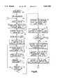
- FIGS. 3A and 3Bare flow chart diagrams illustrating the control process of the weld monitoring system shown in FIG. 1.
- a laser 10transmits a laser beam 12 to a beam delivery system 14.
- the beam 12is directed and focused by suitable focusing optics 16 onto a workpiece 18.
- the workpiece 18is moved in a direction indicated by the arrow 20 by a workpiece transporting device (not shown).
- the laser beam 12is focused on the workpiece 18 at a weld location 22, also referred to as a beam delivery location 22.
- the laser beam, at the weld location 22,has sufficient energy to form a plasma keyhole and effect a weld in a manner known in the art.
- ultraviolet emissionsradiate from the plasma at the weld location 22 and are measured by a light sensor 26 such as a focused photo-detector.
- the output of the light sensor 26is amplified and electronically filtered by an internal signal processor 28.
- the signal processor 28provides an amplified electrical signal indicative of the radiated ultraviolet emissions, i.e., light intensity, from the plasma at the weld location.
- the ultraviolet emissions signalis transmitted by means of a shielded cable 30 to a microcomputer 31.
- the temperature of the re-solidified weld puddleis measured by a temperature sensor 33 such as a focused infrared detector.
- the output from the temperature sensor 33is passed by suitable fiber-optic cabling 34 to a detector/amplifier 35.
- the detector/amplifier 35comprises an optical detector that converts the detected infrared light into an electrical signal.
- An amplifier of the detector/amplifier 35amplifies the electric signal indicative of the infrared light which is, in turn, an electric signal indicative of the weld temperature at the sensing location 32.
- This electrical temperature signalis applied through a noise filter 36 to the microcomputer 31.
- the noise filter 36includes a capacitor 37 and a resistor 38.
- the microcomputer 31may be of conventional design and includes an internal analog-to-digital converter 42 which is supplied with clock pulses from a clock 44.
- the analog-to-digital converter 42receives the amplified signal indicative of the ultraviolet emissions from the internal signal processor 28 and the amplified and filtered signal indicative of the weld temperature from the detector/amplifier 35.
- the digital values of these signalsare supplied to a central processing unit (“CPU") 46 of the microcomputer 31 by way of a memory buffer 48.
- the CPU 46stores the received values of these two signals in a storage device 50, such as a hard disk drive.
- a light intensity waveform and other datamay be displayed under control of the CPU 46 by means of a conventional display unit 52 such as cathode-ray tube.
- the CPU 46is connected to a programmable logic controller ("PLC") 60.
- PLCprogrammable logic controller
- PLC'sare well known in the art and, therefore, PLC 60 is not described in detail.
- the PLC 60controls the welding operations in response to the monitoring system, i.e., in response to the sensed ultraviolet light intensity and the sensed weld temperature.
- the PLC 60starts the welding operations by applying a "start weld" signal on a control line 62 to a laser power supply 64 which, in turn, energizes the laser 10.
- the operation of the laser power supply 64is monitored by the PLC 60 via a feed-back line 66.
- the PLC 60starts a weld operation, it also activates the microcomputer 31 with a trigger signal.
- the PLC 60also communicates with a main frame computer 68.
- the main frame computer 68is used for long term data storage.
- the main frame computer 68facilitates traceability in the event that information is sought at a later time with respect to a particular weld process.
- a workpiece serial numbermay be used to identify particular weld information and permit the computer 68 to find and retrieve that information.
- a graphis shown of the re-solidified weld temperature 70 and the weld light intensity, i.e., the ultraviolet light, 80 as a function of time.
- the weld light intensity curve 80is the average from a plurality of samples taken by the photo detector 26.
- the temperature curve 70 of the re-solidified weld as a function of timeis the average from a plurality of samples taken by the infrared detector 33.
- Each of the curves 70, 80represents a large number of samples by the analog-to-digital converter 42, e.g., 1,410 over a predetermined time interval.
- interval 72there is an initial time delay, shown by interval 72, from the start of welding during which samples or measurements by sensors 26, 33 are not used.
- the trigger delay 72may, in terms of sample time, have a duration of 100 samples.
- Range Ais the portion of the weld process where the laser power and speed is regulated to effect a weld that meets predetermined design penetration requirements. Range A starts when the CPU 46 detects a sample value which represents a threshold light intensity that exceeds a predetermined threshold level 74. This predetermined threshold level denotes a weld of sufficient intensity to meet the predetermined design penetration requirement. This range A covers a majority of the weld. Out of a total of 1,410 samples that would occur over an entire weld process, this range may have a time duration equivalent to the time needed to take 1,000 samples. The final or last range of the weld is designated range B.
- This range Bis the overlap portion of a weld where the light intensity value and the temperature value of the weld increase because the surface location and the ambient temperature of the workpiece are higher due to a previously completed weld bead.
- the light intensity of the plasma in an overlap portionincreases due to the shorter distance from the focusing optics 16 to the workpiece surface 18 at the overlap portion.
- the temperatureincreases in the overlap portion due to the increased ambient surface temperature of the workpiece surface 18.
- Range Bmay have a duration equivalent to the time needed for 300 samplings.
- the weld monitoring systemis employed for evaluating light intensity samples taken from the weld plasma and evaluating the temperature of the re-solidified weld bead during the welding operation.
- Thispermits the detection of process anomalies such as pinholes, interrupted welds, part mismatches, gaps in the part interface, insufficient laser power, and improper rotational speed.
- Such weld anomalieshave repeatable characteristic patterns in the measured light intensity data and in the temperature data.
- the monitoring systememploys known mathematical methods to characterize the temperature and light intensity data, correlate the characterizations to each other, and then compare the results against known patterns from process anomalies.
- the microcomputer 31is programmed, as is discussed below, to perform these calculations, correlations, and comparisons with data stored in the operating program in the CPU 46. Whether the weld is acceptable or not is information that is supplied by the microcomputer 31 to the PLC 60 along with the determined process anomaly which was the cause of the rejection.
- the microcomputer 31displays the light intensity and temperature waveform on its display 52 and also displays the weld acceptability or rejection status as well as the determined process anomaly.
- FIGS. 3A and 3Bshow the control process, in accordance with the present invention, performed by the microcomputer 31.
- the processstarts at step 100 in which various system parameters needed for the control process are entered. These parameters may be entered by any of a plurality of known means such as with a keyboard, a touch screen, bar code reader, or through the storage device (disk drive) 50 reading stored .ini files. The use of .ini files for entry of operating parameters is known in the art.
- the parameters for the control process of the present inventioninclude the duration of test, the test acquisition rate, weighting factors for use in calculation of the empirical values, and limits for use with the empirical values.
- the processproceeds to step 102 where the microcomputer 31 waits for a trigger signal from the PLC 60 to commence data acquisition. For the purpose of understanding the system operation, it is assumed that the trigger signal occurs at step 104.
- the light intensity data and temperature dataare acquired and paired with a clock signal so as to obtain time identified data.
- the acquired datais converted by the analog-to-digital converter 42 at step 108 so as to provide a stream of digital data words representative of respective light intensity samples and temperature samples.
- the data wordsare stored on the hard disk storage 50 device at step 112.
- the CPU 46then starts analyzing the acquired data.
- a clock counteris set to one plus the time value at which the sampled light intensity value first exceeds a threshold light intensity limit 74.
- the first data sample to be analyzedis retrieved from storage device 50 with the remaining samples to be incremented one at a time using an internal pointer.
- the number of samples to be analyzedwas entered. This value is used to determine the number of samples which will be incrementally pulled from the storage device at step 116 to define a cell in a data array.
- step 116calculates the variance for both the temperature and light intensity data. The variance is the square of the standard deviation. These calculated variances are then written to a data buffer array in step 118.
- the internal memory pointeris incremented to point at the next set of data which define the next cell in the data array.
- step 122a determination is made as to whether the maximum number of cells in the data array has been exceeded, i.e., whether the end of the data file has been reached. So long as the end of the data file has not been reached, the program loops through steps 116 through step 122 inclusively. Upon reaching the end of the data file, the determination of step 122 will be affirmative, which allows the program to progress to step 124.
- step 124the temporal locations of the two (2) cells with the two highest variances of light intensity data and the two (2) cells with the two highest variances of temperature data are noted. These cell location times are then compared in step 126. Since the physical locations 22, 32 are spaced apart and the workpiece 18 is moving, the cell location times are adjusted so that the light intensity data and the temperature data used for the comparison relate to the same weld locations on the workpiece. The time adjustment is a function of the distance between the beam delivery location 22 and the sensing location 32, the workpiece speed, and the sampling speed. If, in step 128, either of the two cells with the highest temperature variances is at the same adjusted time location as either of the two cells with the two highest light intensity variances, the program proceeds to step 130. If the determination in step 128 is negative, the process proceeds to step 162 where an acceptance will be written to the PLC 60.
- step 128determines whether the determination in step 128 is positive. If the determination in step 128 is positive, the process proceeds to step 130, where a Fourier transform is performed on the correlated light intensity cell and temperature data cell. This transforms the data from time domain data to frequency domain data. Weighting factors entered in at step 100 are used in step 132 to calculate a light pattern empirical value (LPEV) and a temperature pattern empirical value (TPEV). These empirical values are based on observations of the data frequency responses from known process anomalies.
- LPEVlight pattern empirical value
- TPEVtemperature pattern empirical value
- Empirical testingis used to identify frequency ranges which provide a response for the particular anomalies of concern.
- Both the light intensity data and the temperature datamay have one or more frequency ranges that yield useful information.
- each cellwill have a plurality of amplitude values present within an associated frequency range or ranges.
- the amplitudes of the transformed light data for one of the frequency rangesis summed and that sum is then multiplied by an associated weighting factor.
- the amplitudes of the transformed light date for the other of the frequency rangesis summed and that sum is then multiplied by an associated weighting factor.
- the two productsare then added together to provide the LPEV.
- the value of the TPEVis similarly determined.
- the weighting factorsare determined by the significance of a particular frequency range to identifying an anomaly. For example, if a frequency range provides a significant indication of an anomaly, the weighting factor is 1. If the frequency range provides a less significant indication of an anomaly, the weighting factor can be 0.8.
- step 134the peak-to-peak amplitude (P2P) of the temperature data of the correlated temperature data cell is calculated.
- the LPEVis compared to the empirical light limit value which was loaded in step 100. If the LPEV exceeds the light limit in step 138, a light failure (LF) flag is set to true (or equal to 1) at step 140. The program then progresses to step 142. If the LPEV does not exceed the light limit in step 138, the program progresses directly to step 142.
- LFlight failure
- step 142the TPEV is compared to the empirical temperature limit value loaded in step 100. If the TPEV exceeds the temperature limit in step 144, the program progresses to step 146 wherein the temperature failure (TF) flag is set true (or equal to 1). The program then progresses to step 148. If there is a negative determination in step 144, the program progresses directly to step 148. In step 148, the P2P is compared to its empirical limit which was entered in step 100. If the determination in step 150 is affirmative, the program progresses to step 152 where the P2P failure (P2PF) flag is set true (or equal to 1). The program then progresses to step 154. If the determination is negative in step 150, the program progresses directly to step 154.
- P2PP2P failure
- the sum TF+LF+P2PFis determined in step 154.
- the sum from step 154is compared to the value 2 in step 156. If the sum is greater than or equal to 2 (i.e., more than one of the prior determinations were found to be true), the workpiece is rejected and the program progresses to step 158 wherein a reject code, along with the analysis routine which determined the reject status is written to the PLC 60. The rejection status may also be displayed on display 52. Should the sum in step 156 be found to be less than 2, the program progress to step 160 where an acceptance status is written to the PLC 60. At this point, the acceptance information may be forwarded to the main frame computer 68 by the PLC 60 for archival storage.
- step 162LF, TF, and P2PF are reset to zero.
- the systemthen returns to step 104 for monitoring of another weld process and the determination of the weld acceptability.
Landscapes
- Physics & Mathematics (AREA)
- Optics & Photonics (AREA)
- Engineering & Computer Science (AREA)
- Plasma & Fusion (AREA)
- Mechanical Engineering (AREA)
- Laser Beam Processing (AREA)
Abstract
Description
The present invention is directed to laser welding and is specifically directed to a method and apparatus for monitoring a laser welding process and providing an evaluation of the process.
Laser welding is well known in the art. Systems that monitor a laser welding process and provide an evaluation of the process are also known in the art.
U.S. Pat. No. 4,663,513 to T. Webber discloses use of a laser to deliver energy to a workpiece along a process path for welding purposes. Plasma is produced at a beam delivery point along the process path. A radiation detector is used to detect infrared radiation at a point behind and apart from the location of the beam delivery point. The radiation detector provides an analog temperature signal having a value which varies over time with changes in intensity of the received infrared radiation. The analog temperature signal is compared against a window range of acceptable temperatures. If the temperature signal is not within the window range, a fault signal is produced.
The U.S. Pat. No. 3,262,006 to Sciaky et al. discloses a welding control system having a light sensitive probe and fiber-optics to conduct illumination from an area adjacent a weld to a photo transducer disposed at a remote location. Also, an ultraviolet filter may be employed in the system to see through the flame portion of the weld arc to the inner plasma portion. The U.S. Pat. No. '006 system maintains an electrode at a substantially constant distance from the workpiece.
The U.S. Pat. No. 4,446,354 to Kearney discloses an opto-electronic weld monitoring system employing fiber-optic delivery of incident radiation to a plurality of photo-detectors. The photo-detectors evaluate the weld by separating the received radiation into spectral bands. The output of each photo-detector is compared with a known reference value. A significant deviation in the comparison indicates a fault.
The present invention is directed toward monitoring a laser process in real time by monitoring levels of light intensity from the weld plasma and temperature of the re-solidified weld puddle, comparing the monitored levels at common maximum variance locations to values from known process anomalies, and determining acceptability of the weld based on the comparison.
In accordance with the present invention, an apparatus monitors a weld process in which energy is delivered from a laser source to a workpiece along a process path to create a weld. The apparatus comprises first sensing means for monitoring a first weld characteristic of the weld and for providing an electrical signal indicative of the first weld characteristic. The apparatus also comprises second sensing means for monitoring a second weld characteristic of the weld and for providing an electrical signal indicative of the second weld characteristic. The apparatus further includes means for determining a maximum variance of the first weld characteristic and a maximum variance of the second weld characteristic and for determining if the determined maximum variances of the first and the second weld characteristics occur at locations on the weld which are substantially the same. When the maximum variances of the first and the second weld characteristics occur at locations on the weld which are substantially the same, control means of the apparatus compares the values functionally related to the first and second weld characteristics against associated predetermined anomaly values indicative of a weld anomaly. The apparatus further includes means for producing an error signal when the control means determines that the value functionally related to the first or the second weld characteristic is indicative of a weld anomaly.
Also in accordance with the present invention, a method is provided for monitoring a weld process in which energy is delivered from a laser source to a workpiece along a process path to create a weld. The method comprises the steps of monitoring a first weld characteristic of the weld and providing an electrical signal indicative of said first weld characteristic and monitoring a second weld characteristic of the weld and providing an electrical signal indicative of said second weld characteristic. A maximum variance of the first weld characteristic is determined, as is a maximum variance of the second weld characteristic. The method also includes the step of determining if the determined maximum variances of the first and the second weld characteristics occur at locations on the weld which are substantially the same. When the maximum variances of the first and the second weld characteristics occur at locations on the weld which are substantially the same, values functionally related to the first and second weld characteristics are compared against associated predetermined anomaly values indicative of a weld anomaly. The method further includes the step of producing an error signal when the comparing step determines that the value functionally related to the first or the second weld characteristic is indicative of a weld anomaly.
The foregoing and other advantages of the present invention will become apparent to those skilled in the art after a reading and understanding of the following detailed description with reference to the accompanying drawings in which:
FIG. 1 is a schematic block diagram of a welding and process monitoring system made in accordance with the present invention;
FIG. 2 is a graphical illustration of weld light intensity and temperature of a re-solidified weld puddle with respect to time; and
FIGS. 3A and 3B are flow chart diagrams illustrating the control process of the weld monitoring system shown in FIG. 1.
Referring to FIG. 1, alaser 10 transmits alaser beam 12 to abeam delivery system 14. Thebeam 12 is directed and focused by suitable focusingoptics 16 onto aworkpiece 18. Theworkpiece 18 is moved in a direction indicated by thearrow 20 by a workpiece transporting device (not shown). Thelaser beam 12 is focused on theworkpiece 18 at aweld location 22, also referred to as abeam delivery location 22. The laser beam, at theweld location 22, has sufficient energy to form a plasma keyhole and effect a weld in a manner known in the art.
During the welding process, ultraviolet emissions radiate from the plasma at theweld location 22 and are measured by alight sensor 26 such as a focused photo-detector. The output of thelight sensor 26 is amplified and electronically filtered by aninternal signal processor 28. Thesignal processor 28 provides an amplified electrical signal indicative of the radiated ultraviolet emissions, i.e., light intensity, from the plasma at the weld location. The ultraviolet emissions signal is transmitted by means of a shieldedcable 30 to amicrocomputer 31.
At a sensing location 32 a predetermined distance from thebeam delivery location 22, the temperature of the re-solidified weld puddle is measured by atemperature sensor 33 such as a focused infrared detector. The output from thetemperature sensor 33 is passed by suitable fiber-optic cabling 34 to a detector/amplifier 35. The detector/amplifier 35 comprises an optical detector that converts the detected infrared light into an electrical signal. An amplifier of the detector/amplifier 35 amplifies the electric signal indicative of the infrared light which is, in turn, an electric signal indicative of the weld temperature at thesensing location 32. This electrical temperature signal is applied through anoise filter 36 to themicrocomputer 31. Thenoise filter 36 includes acapacitor 37 and aresistor 38.
Themicrocomputer 31 may be of conventional design and includes an internal analog-to-digital converter 42 which is supplied with clock pulses from aclock 44. The analog-to-digital converter 42 receives the amplified signal indicative of the ultraviolet emissions from theinternal signal processor 28 and the amplified and filtered signal indicative of the weld temperature from the detector/amplifier 35. The digital values of these signals are supplied to a central processing unit ("CPU") 46 of themicrocomputer 31 by way of amemory buffer 48. TheCPU 46 stores the received values of these two signals in astorage device 50, such as a hard disk drive. A light intensity waveform and other data may be displayed under control of theCPU 46 by means of aconventional display unit 52 such as cathode-ray tube.
TheCPU 46 is connected to a programmable logic controller ("PLC") 60. PLC's are well known in the art and, therefore,PLC 60 is not described in detail. ThePLC 60 controls the welding operations in response to the monitoring system, i.e., in response to the sensed ultraviolet light intensity and the sensed weld temperature.
ThePLC 60 starts the welding operations by applying a "start weld" signal on acontrol line 62 to alaser power supply 64 which, in turn, energizes thelaser 10. The operation of thelaser power supply 64 is monitored by thePLC 60 via a feed-back line 66. When thePLC 60 starts a weld operation, it also activates themicrocomputer 31 with a trigger signal. ThePLC 60 also communicates with amain frame computer 68. Themain frame computer 68 is used for long term data storage. Themain frame computer 68 facilitates traceability in the event that information is sought at a later time with respect to a particular weld process. Thus, for example, a workpiece serial number may be used to identify particular weld information and permit thecomputer 68 to find and retrieve that information.
Referring to FIG. 2, a graph is shown of there-solidified weld temperature 70 and the weld light intensity, i.e., the ultraviolet light, 80 as a function of time. The weldlight intensity curve 80 is the average from a plurality of samples taken by thephoto detector 26. Similarly, thetemperature curve 70 of the re-solidified weld as a function of time is the average from a plurality of samples taken by theinfrared detector 33. Each of thecurves digital converter 42, e.g., 1,410 over a predetermined time interval. Initially, there is an initial time delay, shown byinterval 72, from the start of welding during which samples or measurements bysensors trigger delay 72 may, in terms of sample time, have a duration of 100 samples.
Range A is the portion of the weld process where the laser power and speed is regulated to effect a weld that meets predetermined design penetration requirements. Range A starts when theCPU 46 detects a sample value which represents a threshold light intensity that exceeds apredetermined threshold level 74. This predetermined threshold level denotes a weld of sufficient intensity to meet the predetermined design penetration requirement. This range A covers a majority of the weld. Out of a total of 1,410 samples that would occur over an entire weld process, this range may have a time duration equivalent to the time needed to take 1,000 samples. The final or last range of the weld is designated range B. This range B is the overlap portion of a weld where the light intensity value and the temperature value of the weld increase because the surface location and the ambient temperature of the workpiece are higher due to a previously completed weld bead. The light intensity of the plasma in an overlap portion increases due to the shorter distance from the focusingoptics 16 to theworkpiece surface 18 at the overlap portion. The temperature increases in the overlap portion due to the increased ambient surface temperature of theworkpiece surface 18. Range B may have a duration equivalent to the time needed for 300 samplings.
In accordance with the present invention, the weld monitoring system is employed for evaluating light intensity samples taken from the weld plasma and evaluating the temperature of the re-solidified weld bead during the welding operation. This permits the detection of process anomalies such as pinholes, interrupted welds, part mismatches, gaps in the part interface, insufficient laser power, and improper rotational speed. Such weld anomalies have repeatable characteristic patterns in the measured light intensity data and in the temperature data. The monitoring system employs known mathematical methods to characterize the temperature and light intensity data, correlate the characterizations to each other, and then compare the results against known patterns from process anomalies.
Themicrocomputer 31 is programmed, as is discussed below, to perform these calculations, correlations, and comparisons with data stored in the operating program in theCPU 46. Whether the weld is acceptable or not is information that is supplied by themicrocomputer 31 to thePLC 60 along with the determined process anomaly which was the cause of the rejection. Themicrocomputer 31 displays the light intensity and temperature waveform on itsdisplay 52 and also displays the weld acceptability or rejection status as well as the determined process anomaly.
FIGS. 3A and 3B show the control process, in accordance with the present invention, performed by themicrocomputer 31. The process starts atstep 100 in which various system parameters needed for the control process are entered. These parameters may be entered by any of a plurality of known means such as with a keyboard, a touch screen, bar code reader, or through the storage device (disk drive) 50 reading stored .ini files. The use of .ini files for entry of operating parameters is known in the art. The parameters for the control process of the present invention include the duration of test, the test acquisition rate, weighting factors for use in calculation of the empirical values, and limits for use with the empirical values. The process proceeds to step 102 where themicrocomputer 31 waits for a trigger signal from thePLC 60 to commence data acquisition. For the purpose of understanding the system operation, it is assumed that the trigger signal occurs atstep 104.
Atstep 106, the light intensity data and temperature data are acquired and paired with a clock signal so as to obtain time identified data. The acquired data is converted by the analog-to-digital converter 42 atstep 108 so as to provide a stream of digital data words representative of respective light intensity samples and temperature samples. The data words are stored on thehard disk storage 50 device atstep 112. TheCPU 46 then starts analyzing the acquired data.
Atstep 114, a clock counter is set to one plus the time value at which the sampled light intensity value first exceeds a thresholdlight intensity limit 74. The first data sample to be analyzed is retrieved fromstorage device 50 with the remaining samples to be incremented one at a time using an internal pointer. Instep 100, the number of samples to be analyzed was entered. This value is used to determine the number of samples which will be incrementally pulled from the storage device atstep 116 to define a cell in a data array. Once the data of a cell has been loaded intoCPU 46,step 116 calculates the variance for both the temperature and light intensity data. The variance is the square of the standard deviation. These calculated variances are then written to a data buffer array instep 118. Atstep 120, the internal memory pointer is incremented to point at the next set of data which define the next cell in the data array.
The process then proceeds to step 122 where a determination is made as to whether the maximum number of cells in the data array has been exceeded, i.e., whether the end of the data file has been reached. So long as the end of the data file has not been reached, the program loops throughsteps 116 throughstep 122 inclusively. Upon reaching the end of the data file, the determination ofstep 122 will be affirmative, which allows the program to progress to step 124.
Instep 124, the temporal locations of the two (2) cells with the two highest variances of light intensity data and the two (2) cells with the two highest variances of temperature data are noted. These cell location times are then compared instep 126. Since thephysical locations workpiece 18 is moving, the cell location times are adjusted so that the light intensity data and the temperature data used for the comparison relate to the same weld locations on the workpiece. The time adjustment is a function of the distance between thebeam delivery location 22 and thesensing location 32, the workpiece speed, and the sampling speed. If, instep 128, either of the two cells with the highest temperature variances is at the same adjusted time location as either of the two cells with the two highest light intensity variances, the program proceeds to step 130. If the determination instep 128 is negative, the process proceeds to step 162 where an acceptance will be written to thePLC 60.
If the determination instep 128 is positive, the process proceeds to step 130, where a Fourier transform is performed on the correlated light intensity cell and temperature data cell. This transforms the data from time domain data to frequency domain data. Weighting factors entered in atstep 100 are used instep 132 to calculate a light pattern empirical value (LPEV) and a temperature pattern empirical value (TPEV). These empirical values are based on observations of the data frequency responses from known process anomalies.
Empirical testing is used to identify frequency ranges which provide a response for the particular anomalies of concern. Both the light intensity data and the temperature data may have one or more frequency ranges that yield useful information. When the data from the correlated light intensity cell and the temperature cell are converted to the frequency domain, each cell will have a plurality of amplitude values present within an associated frequency range or ranges. For the purpose of explanation, assume the light data is monitored over two separate frequency ranges because empirical data has indicated that these two frequency ranges yield good anomaly information. The amplitudes of the transformed light data for one of the frequency ranges is summed and that sum is then multiplied by an associated weighting factor. The amplitudes of the transformed light date for the other of the frequency ranges is summed and that sum is then multiplied by an associated weighting factor. The two products are then added together to provide the LPEV. The value of the TPEV is similarly determined.
The weighting factors are determined by the significance of a particular frequency range to identifying an anomaly. For example, if a frequency range provides a significant indication of an anomaly, the weighting factor is 1. If the frequency range provides a less significant indication of an anomaly, the weighting factor can be 0.8.
Instep 134, the peak-to-peak amplitude (P2P) of the temperature data of the correlated temperature data cell is calculated. Atstep 136, the LPEV is compared to the empirical light limit value which was loaded instep 100. If the LPEV exceeds the light limit instep 138, a light failure (LF) flag is set to true (or equal to 1) atstep 140. The program then progresses to step 142. If the LPEV does not exceed the light limit instep 138, the program progresses directly to step 142.
Instep 142, the TPEV is compared to the empirical temperature limit value loaded instep 100. If the TPEV exceeds the temperature limit in step 144, the program progresses to step 146 wherein the temperature failure (TF) flag is set true (or equal to 1). The program then progresses to step 148. If there is a negative determination in step 144, the program progresses directly to step 148. Instep 148, the P2P is compared to its empirical limit which was entered instep 100. If the determination instep 150 is affirmative, the program progresses to step 152 where the P2P failure (P2PF) flag is set true (or equal to 1). The program then progresses to step 154. If the determination is negative instep 150, the program progresses directly to step 154.
The sum TF+LF+P2PF is determined instep 154. The sum fromstep 154 is compared to thevalue 2 instep 156. If the sum is greater than or equal to 2 (i.e., more than one of the prior determinations were found to be true), the workpiece is rejected and the program progresses to step 158 wherein a reject code, along with the analysis routine which determined the reject status is written to thePLC 60. The rejection status may also be displayed ondisplay 52. Should the sum instep 156 be found to be less than 2, the program progress to step 160 where an acceptance status is written to thePLC 60. At this point, the acceptance information may be forwarded to themain frame computer 68 by thePLC 60 for archival storage. Instep 162, LF, TF, and P2PF are reset to zero. The temperature and light intensity waveforms, such aswaveforms video display 52 instep 164. The system then returns to step 104 for monitoring of another weld process and the determination of the weld acceptability.
From the above description of the invention, those skilled in the art will perceive improvements, changes and modifications. For example, the determination of LPEV and TPEV have been explained as being determined using Fourier transforms. Those skilled in the art will appreciate that, instead of Fourier transforms, Savitzky-Golay transforms, Hilbert transforms, LaPlace transforms, cubic-spline interpolation, or instantaneous range analysis could be used. Such improvements, changes, and modifications within the skill of the art are intended to be covered by the appended claims.
Claims (18)
1. An apparatus for monitoring a weld process in which energy is delivered from a laser source to a workpiece along a process path to create a weld, said apparatus comprising:
first sensing means for monitoring a first weld characteristic of said weld and providing an electrical signal indicative of said first weld characteristic;
second sensing means for monitoring a second weld characteristic and providing an electrical signal indicative of said second weld characteristic;
means for determining a maximum variance of said first weld characteristic and a maximum variance of said second weld characteristic and for determining if said determined maximum variances of said first and said second weld characteristics occur at locations on said weld which are substantially the same;
control means for, when said maximum variance of said first weld characteristic and said maximum variance of and said second weld characteristic occur at locations on said weld which are substantially the same weld location, comparing values functionally related to said first and second weld characteristics against associated predetermined anomaly values indicative of a weld anomaly; and
means for producing an error signal when said control means determines that the value functionally related to said first or said second weld characteristic is indicative of a weld anomaly.
2. The apparatus of claim 1 wherein said first sensing means senses light intensity of the weld and wherein said second sensing means senses temperature of the weld.
3. The apparatus of claim 2 wherein said first sensing means includes an ultraviolet light sensor and wherein said second sensing means includes an infrared sensor.
4. The apparatus of claim 2 wherein said second sensing means senses the temperature of the weld a predetermined distance from a location at which the energy from the laser source contacts the workpiece.
5. The apparatus of claim 1 wherein said means for determining a maximum variance of said first weld characteristic and said second weld characteristic includes means for determining said variances over discrete samplings of associated data.
6. The apparatus of claim 5 wherein said means for determining a maximum variance determines at least two maximum variance values for both said first weld characteristic and said second weld characteristic.
7. The apparatus of claim 1 including means for recording weld status.
8. An apparatus for monitoring a weld process in which energy is delivered from a laser source to a workpiece along a process path to create a weld, said apparatus comprising:
an ultraviolet light sensor for monitoring ultraviolet light intensity at a location at which the energy from the laser source contacts the workpiece and for providing an electrical signal indicative of said ultraviolet light intensity;
an infrared sensor for monitoring temperature of the weld a predetermined distance from the location at which the energy from the laser source contacts the workpiece and for providing an electrical signal indicative of said temperature;
means for determining a maximum variance of said light intensity and a maximum variance of said weld temperature and for determining if said determined maximum variances occur at locations on said weld which are substantially the same;
control means for, when said maximum variance of said ultraviolet light intensity and said maximum variance of said weld temperature occur at locations on said weld which are substantially the same, comparing values functionally related to said light intensity and weld temperature against associated predetermined anomaly values indicative of a weld anomaly said control means includes means for transforming values of said ultraviolet light intensity and said weld temperature from the time domain to the frequency domain using Fourier transforms prior to the comparisons with their associated anomaly values; and
means for producing an error signal when said comparing means determines that transformed values of said ultraviolet light intensity or said weld temperature are indicative of a weld anomaly.
9. A method for monitoring a weld process in which energy is delivered from a laser source to a workpiece along a process path to create a weld, said method comprising the steps of:
monitoring a first weld characteristic of said weld and providing an electrical signal indicative of said first weld characteristic;
monitoring a second weld characteristic of said weld and providing an electrical signal indicative of said second weld characteristic;
determining a maximum variance of said first weld characteristic and a maximum variance of said second weld characteristic;
determining if said determined maximum variances of said first and said second weld characteristics occur at locations on said weld which are substantially the same;
comparing, when said maximum variances of said first and said second weld characteristics occur at locations on said weld which are substantially the same, values functionally related to said first and second weld characteristics against associated predetermined anomaly values indicative of a weld anomaly; and
producing an error signal when said comparing step determines that the value functionally related to said first or said second weld characteristic is indicative of a weld anomaly.
10. The method of claim 9 wherein said step of monitoring said first weld characteristic includes monitoring light intensity at the location at which energy from said laser source contacts the workpiece and wherein said step of monitoring said second weld characteristic includes monitoring weld temperature at a location spaced from said location at which energy from said laser source contacts the workpiece.
11. The method of claim 10 wherein said step of monitoring light intensity includes monitoring ultraviolet light and wherein said step of monitoring weld temperature includes monitoring infrared energy.
12. The method of claim 9 further including the step of recording the weld status.
13. The method of claim 9 wherein said step of determining a maximum variance of said first weld characteristic and said second weld characteristic includes determining said variances over discrete samplings of associated data.
14. The method of claim 13 wherein said step of determining a maximum variance determines at least two maximum variance values for both said first weld characteristic and said second weld characteristic.
15. An apparatus for monitoring a weld process in which energy is delivered from a laser source to a workpiece along a process path to create a weld, said apparatus comprising:
first sensing means for monitoring a first weld characteristic of said weld and providing an electrical signal indicative of said first weld characteristic;
second sensing means for monitoring a second weld characteristic and providing an electrical signal indicative of said second weld characteristic;
means for determining a maximum variance of said first weld characteristic and a maximum variance of said second weld characteristic and for determining if said determined maximum variances of said first and said second weld characteristics occur at locations on said weld which are substantially the same;
control means for, when said maximum variance of said first weld characteristic and said maximum variance of said second weld characteristic occur at locations on said weld which are substantially the same weld location, comparing values functionally related to said first and second weld characteristics against associated predetermined anomaly values indicative of a weld anomaly; and
means for producing an error signal when said control means determines that the value functionally related to said first or said second weld characteristic is indicative of a weld anomaly;
said control means including means for determining said values functionally related to said first and said second weld characteristics and including means for transforming values of said first and second weld characteristics from a time domain value to a frequency domain prior to the comparisons with their associated anomaly values.
16. The apparatus of claim 15 wherein said means for transforming includes means for determining a Fourier transform.
17. A method for monitoring a weld process in which energy is delivered from a laser source to a workpiece along a process path to create a weld, said method comprising the steps of:
monitoring a first weld characteristic of said weld and providing an electrical signal indicative of said first weld characteristic;
monitoring a second weld characteristic of said weld and providing an electrical signal indicative of said second weld characteristic;
determining a maximum variance of said first weld characteristic and a maximum variance of said second weld characteristic;
determining if said determined maximum variances of said first and said second weld characteristics occur at locations on said weld which are substantially the same;
comparing, when said maximum variances of said first and said second weld characteristics occur at locations on said weld which are substantially the same, values functionally related to said first and second weld characteristics against associated predetermined anomaly values indicative of a weld anomaly; and
producing an error signal when said comparing step determines that the value functionally related to said first or said second weld characteristic is indicative of a weld anomaly;
said step of comparing including the step of transforming values of said first and second characteristics from a time domain value to a frequency domain value prior to the comparing with their associated anomaly values.
18. The method of claim 17 wherein said step of transforming includes determining a Fourier transform of said first and second characteristics.
Priority Applications (1)
| Application Number | Priority Date | Filing Date | Title |
|---|---|---|---|
| US08/542,281US5651903A (en) | 1995-10-12 | 1995-10-12 | Method and apparatus for evaluating laser welding |
Applications Claiming Priority (1)
| Application Number | Priority Date | Filing Date | Title |
|---|---|---|---|
| US08/542,281US5651903A (en) | 1995-10-12 | 1995-10-12 | Method and apparatus for evaluating laser welding |
Publications (1)
| Publication Number | Publication Date |
|---|---|
| US5651903Atrue US5651903A (en) | 1997-07-29 |
Family
ID=24163114
Family Applications (1)
| Application Number | Title | Priority Date | Filing Date |
|---|---|---|---|
| US08/542,281Expired - Fee RelatedUS5651903A (en) | 1995-10-12 | 1995-10-12 | Method and apparatus for evaluating laser welding |
Country Status (1)
| Country | Link |
|---|---|
| US (1) | US5651903A (en) |
Cited By (55)
| Publication number | Priority date | Publication date | Assignee | Title |
|---|---|---|---|---|
| US5968376A (en)* | 1998-08-19 | 1999-10-19 | Trw Inc. | Method for infrared inspection of resistence welds during assembling of an inflator |
| US6084223A (en)* | 1997-06-13 | 2000-07-04 | Jurca Optoelektronik | Method of welding workpieces and apparatus for carrying it out |
| WO2000041837A1 (en)* | 1999-01-14 | 2000-07-20 | Powerlasers Limited | Method for laser processing fault detection |
| WO2000041836A1 (en)* | 1999-01-14 | 2000-07-20 | Powerlasers Limited | Structured multi-spot detecting technique for adaptive control of laser beam processing |
| US6188041B1 (en) | 1998-11-13 | 2001-02-13 | Korea Atomic Energy Research Institute | Method and apparatus for real-time weld process monitoring in a pulsed laser welding |
| US6329635B1 (en)* | 1998-10-30 | 2001-12-11 | The University Of Chicago | Methods for weld monitoring and laser heat treatment monitoring |
| WO2002002268A1 (en)* | 2000-07-06 | 2002-01-10 | Aerospatiale Matra Ccr | Method for detecting and identifying defects in a laser beam weld seam |
| US6377904B1 (en)* | 1998-06-03 | 2002-04-23 | Suzuki Motor Corporation | Welding laser focal point position detecting apparatus |
| EP1238744A1 (en)* | 2001-02-23 | 2002-09-11 | Nissan Motor Co., Ltd. | Laser weld quality monitoring method and system |
| US6585146B2 (en)* | 2000-01-06 | 2003-07-01 | Thermal Wave Imaging, Inc. | Automated non-destructive weld evaluation method and apparatus |
| EP1361015A1 (en)* | 2002-05-07 | 2003-11-12 | C.R.F. Società Consortile per Azioni | System and method for monitoring laser welds, particularly in tailored blanks |
| US6670574B1 (en) | 2002-07-31 | 2003-12-30 | Unitek Miyachi Corporation | Laser weld monitor |
| US6679628B2 (en)* | 2001-08-14 | 2004-01-20 | Schneider Automation Inc. | Solid state temperature measuring device and method |
| WO2004020142A3 (en)* | 2002-08-27 | 2004-07-15 | Usinor | Device and method for controlling an operation involving the laser beam welding, hardfacing or machining of a part |
| US6822188B1 (en)* | 1998-10-07 | 2004-11-23 | Fraunhofer-Gesellschaft Zur Forderung Der Angewandten Forschung E.V. | Method for shaping materials with plasma-inducing high-energy radiation |
| US20040249495A1 (en)* | 2003-06-03 | 2004-12-09 | Orozco Nelson J. | Laser welding control system |
| US20050011867A1 (en)* | 2003-07-16 | 2005-01-20 | Fanuc Ltd | Laser welding unit |
| EP1555082A1 (en)* | 2004-01-13 | 2005-07-20 | C.R.F. Società Consortile per Azioni | A method for controlling the quality of industrial processes, in particular laser-welding processes |
| WO2005082568A1 (en)* | 2004-02-27 | 2005-09-09 | National Institute For Materials Science | Laser welding method |
| US20070084835A1 (en)* | 2005-09-23 | 2007-04-19 | Dinauer William R | No gap laser welding of coated steel |
| US20100123080A1 (en)* | 2008-11-20 | 2010-05-20 | Benteler Automobiltechnik Gmbh | Process and system for the nondestructive quality determination of a weld seam, and a welding device |
| US20100314362A1 (en)* | 2009-06-11 | 2010-12-16 | Illinois Tool Works Inc. | Weld defect detection systems and methods for laser hybrid welding |
| WO2012146444A1 (en) | 2011-04-28 | 2012-11-01 | Westinghouse Electric Sweden Ab | Method of laser welding a nuclear fuel rod |
| US20120325792A1 (en)* | 2011-06-27 | 2012-12-27 | Illinois Tool Works Inc. | Workpiece-based setting of weld parameters |
| EP2567773A1 (en) | 2011-09-08 | 2013-03-13 | TRUMPF Werkzeugmaschinen GmbH + Co. KG | Method for inspecting seam quality during a laser welding process |
| US20140048517A1 (en)* | 2009-06-11 | 2014-02-20 | Illinois Tool Works Inc. | Systems and methods for diagnosing secondary weld errors |
| WO2014155188A1 (en)* | 2013-03-29 | 2014-10-02 | Toyota Jidosha Kabushiki Kaisha | Welding portion inspection device and inspection method therefor |
| WO2014155191A3 (en)* | 2013-03-29 | 2014-12-04 | Toyota Jidosha Kabushiki Kaisha | Welded portion inspection apparatus and inspection method thereof |
| CN104874910A (en)* | 2014-02-28 | 2015-09-02 | 丰田自动车株式会社 | Welded portion inspection method |
| US9266182B2 (en) | 2012-04-06 | 2016-02-23 | Illinois Tools Works Inc. | Welding torch with a temperature measurement device |
| US20160052091A1 (en)* | 2013-03-29 | 2016-02-25 | Toyota Jidosha Kabushiki Kaisha | Welded portion inspection apparatus and inspection method thereof, with inspection in different zones of the molten pool |
| US20160067832A1 (en)* | 2013-04-15 | 2016-03-10 | Toyota Jidosha Kabushiki Kaisha | Welding portion inspection device and inspection method therefore, with extracting portion for extracting evaporation luminescence and thermal radiation |
| US20160074963A1 (en)* | 2014-09-16 | 2016-03-17 | Honeywell International Inc. | Turbocharger shaft and wheel assembly |
| US9415459B2 (en) | 2012-04-06 | 2016-08-16 | Illinois Tool Works Inc. | Welding systems having non-contact temperature measurement systems |
| US9573224B2 (en) | 2014-09-02 | 2017-02-21 | Product Innovation & Engineering, LLC | System and method for determining beam power level along an additive deposition path |
| US9757902B2 (en) | 2014-09-02 | 2017-09-12 | Product Innovation and Engineering L.L.C. | Additive layering method using improved build description |
| US9827631B2 (en) | 2014-09-16 | 2017-11-28 | Honeywell International Inc. | Turbocharger shaft and wheel assembly |
| US9937577B2 (en) | 2006-12-20 | 2018-04-10 | Lincoln Global, Inc. | System for a welding sequencer |
| US10024166B2 (en) | 2014-09-16 | 2018-07-17 | Honeywell International Inc. | Turbocharger shaft and wheel assembly |
| US10041351B2 (en) | 2014-09-16 | 2018-08-07 | Honeywell International Inc. | Turbocharger shaft and wheel assembly |
| US20190022787A1 (en)* | 2017-07-24 | 2019-01-24 | Lincoln Global, Inc. | Weld sequencer part inspector |
| US10496080B2 (en) | 2006-12-20 | 2019-12-03 | Lincoln Global, Inc. | Welding job sequencer |
| US10632566B2 (en) | 2014-12-02 | 2020-04-28 | Product Innovation and Engineering L.L.C. | System and method for controlling the input energy from an energy point source during metal processing |
| US10682720B2 (en) | 2012-09-07 | 2020-06-16 | Illinois Tool Works Inc. | Welding systems and devices having a configurable personal computer user interface |
| JP2021058927A (en)* | 2019-10-09 | 2021-04-15 | パナソニックIpマネジメント株式会社 | Laser welding quality detecting method and laser welding quality detecting device |
| US10994358B2 (en) | 2006-12-20 | 2021-05-04 | Lincoln Global, Inc. | System and method for creating or modifying a welding sequence based on non-real world weld data |
| US10994357B2 (en) | 2006-12-20 | 2021-05-04 | Lincoln Global, Inc. | System and method for creating or modifying a welding sequence |
| US11072034B2 (en) | 2006-12-20 | 2021-07-27 | Lincoln Global, Inc. | System and method of exporting or using welding sequencer data for external systems |
| US11103948B2 (en) | 2014-08-18 | 2021-08-31 | Illinois Tool Works Inc. | Systems and methods for a personally allocated interface for use in a welding system |
| US11154946B2 (en) | 2014-06-30 | 2021-10-26 | Illinois Tool Works Inc. | Systems and methods for the control of welding parameters |
| US20220118548A1 (en)* | 2020-10-16 | 2022-04-21 | Trumpf Laser- Und Systemtechnik Gmbh | Method and processing machine for pore defect monitoring of a laser welding process for welding a plurality of bar conductors and associated computer program product |
| FR3116744A1 (en) | 2020-11-27 | 2022-06-03 | Societe D'assemblages Par Faisceaux D'electrons Et Laser | Laser machine and manufacturing process with plasma threshold detection |
| US20230129188A1 (en)* | 2015-07-29 | 2023-04-27 | Illinois Tool Works Inc. | System and Method to Facilitate Welding Software as a Service |
| FR3134735A1 (en) | 2022-04-20 | 2023-10-27 | Societe D'assemblage Par Faisceaux D'electrons Et Laser | Laser machine comprising two nozzles and associated manufacturing method |
| US11839915B2 (en) | 2021-01-20 | 2023-12-12 | Product Innovation and Engineering LLC | System and method for determining beam power level along an additive deposition path |
Citations (9)
| Publication number | Priority date | Publication date | Assignee | Title |
|---|---|---|---|---|
| US3262006A (en)* | 1963-12-27 | 1966-07-19 | Welding Research Inc | Welding control system |
| US4446354A (en)* | 1981-05-29 | 1984-05-01 | The United States Of America As Represented By The Secretary Of The Army | Optoelectronic weld evaluation system |
| US4663513A (en)* | 1985-11-26 | 1987-05-05 | Spectra-Physics, Inc. | Method and apparatus for monitoring laser processes |
| US4992643A (en)* | 1989-08-25 | 1991-02-12 | United States Department Of Energy | Method and device for controlling plume during laser welding |
| WO1993003881A1 (en)* | 1991-08-24 | 1993-03-04 | Cmb Foodcan Plc | Apparatus and method for monitoring laser material processing |
| JPH05337663A (en)* | 1991-10-22 | 1993-12-21 | Mitsubishi Heavy Ind Ltd | Welding state monitor |
| US5272312A (en)* | 1989-03-14 | 1993-12-21 | Jurca Marius Christian | Process for quality control of laser beam welding and cutting |
| US5283416A (en)* | 1992-06-26 | 1994-02-01 | Trw Inc. | Laser process monitoring and evaluation |
| US5486677A (en)* | 1991-02-26 | 1996-01-23 | Fraunhofer-Gesellschaft Zur Forderung Der Angewandten Forschung E.V. | Method of and apparatus for machining workpieces with a laser beam |
- 1995
- 1995-10-12USUS08/542,281patent/US5651903A/ennot_activeExpired - Fee Related
Patent Citations (10)
| Publication number | Priority date | Publication date | Assignee | Title |
|---|---|---|---|---|
| US3262006A (en)* | 1963-12-27 | 1966-07-19 | Welding Research Inc | Welding control system |
| US4446354A (en)* | 1981-05-29 | 1984-05-01 | The United States Of America As Represented By The Secretary Of The Army | Optoelectronic weld evaluation system |
| US4663513A (en)* | 1985-11-26 | 1987-05-05 | Spectra-Physics, Inc. | Method and apparatus for monitoring laser processes |
| US5272312A (en)* | 1989-03-14 | 1993-12-21 | Jurca Marius Christian | Process for quality control of laser beam welding and cutting |
| US4992643A (en)* | 1989-08-25 | 1991-02-12 | United States Department Of Energy | Method and device for controlling plume during laser welding |
| US5486677A (en)* | 1991-02-26 | 1996-01-23 | Fraunhofer-Gesellschaft Zur Forderung Der Angewandten Forschung E.V. | Method of and apparatus for machining workpieces with a laser beam |
| WO1993003881A1 (en)* | 1991-08-24 | 1993-03-04 | Cmb Foodcan Plc | Apparatus and method for monitoring laser material processing |
| JPH05337663A (en)* | 1991-10-22 | 1993-12-21 | Mitsubishi Heavy Ind Ltd | Welding state monitor |
| US5283416A (en)* | 1992-06-26 | 1994-02-01 | Trw Inc. | Laser process monitoring and evaluation |
| US5360960A (en)* | 1992-06-26 | 1994-11-01 | Trw Inc. | Light intensity weld monitor |
Cited By (100)
| Publication number | Priority date | Publication date | Assignee | Title |
|---|---|---|---|---|
| US6084223A (en)* | 1997-06-13 | 2000-07-04 | Jurca Optoelektronik | Method of welding workpieces and apparatus for carrying it out |
| US6377904B1 (en)* | 1998-06-03 | 2002-04-23 | Suzuki Motor Corporation | Welding laser focal point position detecting apparatus |
| US5968376A (en)* | 1998-08-19 | 1999-10-19 | Trw Inc. | Method for infrared inspection of resistence welds during assembling of an inflator |
| US6822188B1 (en)* | 1998-10-07 | 2004-11-23 | Fraunhofer-Gesellschaft Zur Forderung Der Angewandten Forschung E.V. | Method for shaping materials with plasma-inducing high-energy radiation |
| US6329635B1 (en)* | 1998-10-30 | 2001-12-11 | The University Of Chicago | Methods for weld monitoring and laser heat treatment monitoring |
| US6188041B1 (en) | 1998-11-13 | 2001-02-13 | Korea Atomic Energy Research Institute | Method and apparatus for real-time weld process monitoring in a pulsed laser welding |
| WO2000041837A1 (en)* | 1999-01-14 | 2000-07-20 | Powerlasers Limited | Method for laser processing fault detection |
| WO2000041836A1 (en)* | 1999-01-14 | 2000-07-20 | Powerlasers Limited | Structured multi-spot detecting technique for adaptive control of laser beam processing |
| US6585146B2 (en)* | 2000-01-06 | 2003-07-01 | Thermal Wave Imaging, Inc. | Automated non-destructive weld evaluation method and apparatus |
| WO2002002268A1 (en)* | 2000-07-06 | 2002-01-10 | Aerospatiale Matra Ccr | Method for detecting and identifying defects in a laser beam weld seam |
| FR2811427A1 (en)* | 2000-07-06 | 2002-01-11 | Aerospatiale Matra Ccr | METHOD FOR DETECTION AND IDENTIFICATION OF DEFECTS IN A WELDING CORD MADE BY LASER BEAM |
| US6937329B2 (en) | 2000-07-06 | 2005-08-30 | Aerospatiale Matra Ccr | Method for detecting and identifying defects in a laser beam weld seam |
| US20040032597A1 (en)* | 2000-07-06 | 2004-02-19 | Bruno Esmiller | Method for detecting and identifying defects in a laser beam weld seam |
| EP1238744A1 (en)* | 2001-02-23 | 2002-09-11 | Nissan Motor Co., Ltd. | Laser weld quality monitoring method and system |
| US6710283B2 (en) | 2001-02-23 | 2004-03-23 | Nissan Motor Co., Ltd. | Laser weld quality monitoring method and system |
| US6679628B2 (en)* | 2001-08-14 | 2004-01-20 | Schneider Automation Inc. | Solid state temperature measuring device and method |
| US7048438B2 (en) | 2001-08-14 | 2006-05-23 | Schneider Automatic Inc. | Solid state temperature measuring device and method |
| EP1361015A1 (en)* | 2002-05-07 | 2003-11-12 | C.R.F. Società Consortile per Azioni | System and method for monitoring laser welds, particularly in tailored blanks |
| US20040069754A1 (en)* | 2002-07-31 | 2004-04-15 | Gregory Bates | Laser weld Monitor |
| US7129438B2 (en) | 2002-07-31 | 2006-10-31 | Miyachi Unitek Corporation | Laser weld monitor |
| US6670574B1 (en) | 2002-07-31 | 2003-12-30 | Unitek Miyachi Corporation | Laser weld monitor |
| WO2004020142A3 (en)* | 2002-08-27 | 2004-07-15 | Usinor | Device and method for controlling an operation involving the laser beam welding, hardfacing or machining of a part |
| US20060086705A1 (en)* | 2002-08-27 | 2006-04-27 | Usinor | Device and method for controlling an operation involving the laser beam welding, hardfacing or machining of a part |
| US20040249495A1 (en)* | 2003-06-03 | 2004-12-09 | Orozco Nelson J. | Laser welding control system |
| US7107118B2 (en)* | 2003-06-03 | 2006-09-12 | Applied Thermal Sciences, Inc. | Laser welding control system |
| US20050011867A1 (en)* | 2003-07-16 | 2005-01-20 | Fanuc Ltd | Laser welding unit |
| US20050179970A1 (en)* | 2004-01-13 | 2005-08-18 | C.R.F. Societa Consortile Per Azioni | Method for controlling the quality of industrial processes, in particular laser-welding processes |
| US20100228377A1 (en)* | 2004-01-13 | 2010-09-09 | C.R.F. Societa Consortile Per Azioni | Method for controlling the quality of industrial processes, in particular laser-welding processes |
| EP1555082A1 (en)* | 2004-01-13 | 2005-07-20 | C.R.F. Società Consortile per Azioni | A method for controlling the quality of industrial processes, in particular laser-welding processes |
| US8571823B2 (en) | 2004-01-13 | 2013-10-29 | Crf Societa Consortile Per Azioni | Method for controlling the quality of industrial processes, in particular laser-welding processes |
| US7728254B2 (en) | 2004-01-13 | 2010-06-01 | Crf Societa Consortile Per Azioni | Method for controlling the quality of industrial processes, in particular laser-welding processes |
| CN100451895C (en)* | 2004-01-13 | 2009-01-14 | C.R.F.阿西安尼顾问公司 | Method for controlling quality of industry process especially of laser welding process |
| RU2368931C2 (en)* | 2004-01-13 | 2009-09-27 | К.Р.Ф. Сочиета Консортиле Пер Ациони | Method to control production process quality, particularly that of laser welding |
| US20070289955A1 (en)* | 2004-02-27 | 2007-12-20 | Susumu Tsukamoto | Laser Welding Method |
| WO2005082568A1 (en)* | 2004-02-27 | 2005-09-09 | National Institute For Materials Science | Laser welding method |
| US7910855B2 (en)* | 2005-09-23 | 2011-03-22 | Lasx Industries, Inc. | No gap laser welding of coated steel |
| US20070084835A1 (en)* | 2005-09-23 | 2007-04-19 | Dinauer William R | No gap laser welding of coated steel |
| US10994357B2 (en) | 2006-12-20 | 2021-05-04 | Lincoln Global, Inc. | System and method for creating or modifying a welding sequence |
| US11072034B2 (en) | 2006-12-20 | 2021-07-27 | Lincoln Global, Inc. | System and method of exporting or using welding sequencer data for external systems |
| US10994358B2 (en) | 2006-12-20 | 2021-05-04 | Lincoln Global, Inc. | System and method for creating or modifying a welding sequence based on non-real world weld data |
| US10940555B2 (en) | 2006-12-20 | 2021-03-09 | Lincoln Global, Inc. | System for a welding sequencer |
| US10496080B2 (en) | 2006-12-20 | 2019-12-03 | Lincoln Global, Inc. | Welding job sequencer |
| US11980976B2 (en) | 2006-12-20 | 2024-05-14 | Lincoln Global, Inc. | Method for a welding sequencer |
| US9937577B2 (en) | 2006-12-20 | 2018-04-10 | Lincoln Global, Inc. | System for a welding sequencer |
| US20100123080A1 (en)* | 2008-11-20 | 2010-05-20 | Benteler Automobiltechnik Gmbh | Process and system for the nondestructive quality determination of a weld seam, and a welding device |
| US8541746B2 (en)* | 2008-11-20 | 2013-09-24 | Benteler Automobiltechnik Gmbh | Process and system for the nondestructive quality determination of a weld seam, and a welding device |
| US9095930B2 (en) | 2009-06-11 | 2015-08-04 | Illinois Tool Works Inc. | Weld defect detection systems and methods for laser hybrid welding |
| US20140048517A1 (en)* | 2009-06-11 | 2014-02-20 | Illinois Tool Works Inc. | Systems and methods for diagnosing secondary weld errors |
| US20100314362A1 (en)* | 2009-06-11 | 2010-12-16 | Illinois Tool Works Inc. | Weld defect detection systems and methods for laser hybrid welding |
| US8927902B2 (en)* | 2009-06-11 | 2015-01-06 | Illinois Tool Works Inc. | Systems and methods for diagnosing secondary weld errors |
| US9498852B2 (en) | 2009-06-11 | 2016-11-22 | Illinois Tool Works Inc. | Weld defect detection systems and methods for laser hybrid welding |
| US9108264B2 (en) | 2009-06-11 | 2015-08-18 | Illinois Tool Works Inc. | Systems and methods for diagnosing secondary weld errors |
| US9381591B2 (en) | 2009-06-11 | 2016-07-05 | Illinois Tool Works Inc. | Systems and methods for diagnosing secondary weld errors |
| US10695868B2 (en) | 2009-06-11 | 2020-06-30 | Illinois Tool Works Inc. | Laser hybrid welding control systems and methods |
| US8552337B2 (en) | 2009-06-11 | 2013-10-08 | Illinois Tool Works Inc. | Weld defect detection systems and methods for laser hybrid welding |
| US10239158B2 (en) | 2009-06-11 | 2019-03-26 | Illinois Tool Works Inc. | Laser hybrid welding control systems and methods |
| WO2012146444A1 (en) | 2011-04-28 | 2012-11-01 | Westinghouse Electric Sweden Ab | Method of laser welding a nuclear fuel rod |
| US9586287B2 (en) | 2011-04-28 | 2017-03-07 | Westinghouse Electric Sweden Ab | Method of laser welding a nuclear fuel rod |
| US11931836B2 (en) | 2011-06-27 | 2024-03-19 | Illinois Tool Works Inc. | Workpiece-based setting of weld parameters |
| US10888947B2 (en)* | 2011-06-27 | 2021-01-12 | Illinois Tool Works Inc. | Workpiece-based setting of weld parameters |
| US20120325792A1 (en)* | 2011-06-27 | 2012-12-27 | Illinois Tool Works Inc. | Workpiece-based setting of weld parameters |
| CN102990224B (en)* | 2011-09-08 | 2016-06-01 | 通快机床两合公司 | For checking the method for weldquality during laser beam welding |
| EP2567773A1 (en) | 2011-09-08 | 2013-03-13 | TRUMPF Werkzeugmaschinen GmbH + Co. KG | Method for inspecting seam quality during a laser welding process |
| US8890023B2 (en) | 2011-09-08 | 2014-11-18 | Trumpf Werkzeugmaschinen Gmbh + Co. Kg | Method of verifying seam quality during a laser welding process |
| CN102990224A (en)* | 2011-09-08 | 2013-03-27 | 通快机床两合公司 | Method for inspecting seam quality during a laser welding process |
| US10537956B2 (en) | 2012-04-06 | 2020-01-21 | Illinois Tool Works Inc. | Welding torch with a temperature measurement device |
| US11504791B2 (en)* | 2012-04-06 | 2022-11-22 | Illinois Tool Works Inc. | Welding torch with a temperature measurement device |
| US11110537B2 (en) | 2012-04-06 | 2021-09-07 | Illinois Tool Works Inc. | Welding systems having non-contact temperature measurement systems |
| US9266182B2 (en) | 2012-04-06 | 2016-02-23 | Illinois Tools Works Inc. | Welding torch with a temperature measurement device |
| US9415459B2 (en) | 2012-04-06 | 2016-08-16 | Illinois Tool Works Inc. | Welding systems having non-contact temperature measurement systems |
| US20160144445A1 (en)* | 2012-04-06 | 2016-05-26 | Illinois Tool Works Inc. | Welding torch with a temperature measurement device |
| US12115605B2 (en) | 2012-09-07 | 2024-10-15 | Illinois Tool Works Inc. | Welding systems and devices having a configurable personal computer user interface |
| US10682720B2 (en) | 2012-09-07 | 2020-06-16 | Illinois Tool Works Inc. | Welding systems and devices having a configurable personal computer user interface |
| US20160052091A1 (en)* | 2013-03-29 | 2016-02-25 | Toyota Jidosha Kabushiki Kaisha | Welded portion inspection apparatus and inspection method thereof, with inspection in different zones of the molten pool |
| CN105102173A (en)* | 2013-03-29 | 2015-11-25 | 丰田自动车株式会社 | Welding inspection device and inspection method thereof |
| US9506862B2 (en) | 2013-03-29 | 2016-11-29 | Toyota Jidosha Kabushiki Kaisha | Welded portion inspection apparatus and inspection method thereof |
| WO2014155191A3 (en)* | 2013-03-29 | 2014-12-04 | Toyota Jidosha Kabushiki Kaisha | Welded portion inspection apparatus and inspection method thereof |
| WO2014155188A1 (en)* | 2013-03-29 | 2014-10-02 | Toyota Jidosha Kabushiki Kaisha | Welding portion inspection device and inspection method therefor |
| US9517533B2 (en)* | 2013-03-29 | 2016-12-13 | Toyota Jidosha Kabushiki Kaisha | Welded portion inspection apparatus and inspection method thereof, with inspection in different zones of the molten pool |
| US20160067832A1 (en)* | 2013-04-15 | 2016-03-10 | Toyota Jidosha Kabushiki Kaisha | Welding portion inspection device and inspection method therefore, with extracting portion for extracting evaporation luminescence and thermal radiation |
| US9527166B2 (en)* | 2013-04-15 | 2016-12-27 | Toyota Jidosha Kabushiki Kaisha | Welding portion inspection device and inspection method therefore, with extracting portion for extracting evaporation luminescence and thermal radiation |
| CN104874910A (en)* | 2014-02-28 | 2015-09-02 | 丰田自动车株式会社 | Welded portion inspection method |
| US11154946B2 (en) | 2014-06-30 | 2021-10-26 | Illinois Tool Works Inc. | Systems and methods for the control of welding parameters |
| US11103948B2 (en) | 2014-08-18 | 2021-08-31 | Illinois Tool Works Inc. | Systems and methods for a personally allocated interface for use in a welding system |
| US12042889B2 (en) | 2014-08-18 | 2024-07-23 | Illinois Tool Works Inc. | Systems and methods for a personally allocated interface for use in a welding system |
| US9573224B2 (en) | 2014-09-02 | 2017-02-21 | Product Innovation & Engineering, LLC | System and method for determining beam power level along an additive deposition path |
| US9757902B2 (en) | 2014-09-02 | 2017-09-12 | Product Innovation and Engineering L.L.C. | Additive layering method using improved build description |
| US9827631B2 (en) | 2014-09-16 | 2017-11-28 | Honeywell International Inc. | Turbocharger shaft and wheel assembly |
| US9821410B2 (en)* | 2014-09-16 | 2017-11-21 | Honeywell International Inc. | Turbocharger shaft and wheel assembly |
| US20160074963A1 (en)* | 2014-09-16 | 2016-03-17 | Honeywell International Inc. | Turbocharger shaft and wheel assembly |
| US10024166B2 (en) | 2014-09-16 | 2018-07-17 | Honeywell International Inc. | Turbocharger shaft and wheel assembly |
| US10041351B2 (en) | 2014-09-16 | 2018-08-07 | Honeywell International Inc. | Turbocharger shaft and wheel assembly |
| US10632566B2 (en) | 2014-12-02 | 2020-04-28 | Product Innovation and Engineering L.L.C. | System and method for controlling the input energy from an energy point source during metal processing |
| US20230129188A1 (en)* | 2015-07-29 | 2023-04-27 | Illinois Tool Works Inc. | System and Method to Facilitate Welding Software as a Service |
| US20190022787A1 (en)* | 2017-07-24 | 2019-01-24 | Lincoln Global, Inc. | Weld sequencer part inspector |
| JP2021058927A (en)* | 2019-10-09 | 2021-04-15 | パナソニックIpマネジメント株式会社 | Laser welding quality detecting method and laser welding quality detecting device |
| US20220118548A1 (en)* | 2020-10-16 | 2022-04-21 | Trumpf Laser- Und Systemtechnik Gmbh | Method and processing machine for pore defect monitoring of a laser welding process for welding a plurality of bar conductors and associated computer program product |
| FR3116744A1 (en) | 2020-11-27 | 2022-06-03 | Societe D'assemblages Par Faisceaux D'electrons Et Laser | Laser machine and manufacturing process with plasma threshold detection |
| US11839915B2 (en) | 2021-01-20 | 2023-12-12 | Product Innovation and Engineering LLC | System and method for determining beam power level along an additive deposition path |
| FR3134735A1 (en) | 2022-04-20 | 2023-10-27 | Societe D'assemblage Par Faisceaux D'electrons Et Laser | Laser machine comprising two nozzles and associated manufacturing method |
Similar Documents
| Publication | Publication Date | Title |
|---|---|---|
| US5651903A (en) | Method and apparatus for evaluating laser welding | |
| US5360960A (en) | Light intensity weld monitor | |
| US5674415A (en) | Method and apparatus for real time weld monitoring | |
| EP3339842B1 (en) | Raman spectrum-based object inspection apparatus and method | |
| CN207779896U (en) | Raman spectrum detection device | |
| US6188041B1 (en) | Method and apparatus for real-time weld process monitoring in a pulsed laser welding | |
| US5026979A (en) | Method and apparatus for optically monitoring laser materials processing | |
| JP4504117B2 (en) | How to determine the depth of a defect | |
| US4446354A (en) | Optoelectronic weld evaluation system | |
| US3986391A (en) | Method and apparatus for the real-time monitoring of a continuous weld using stress-wave emission techniques | |
| EP2567202B1 (en) | Beam scattering laser monitoring apparatus | |
| US20240261907A1 (en) | Laser welding quality inspection method and laser welding quality inspection apparatus | |
| KR20070116772A (en) | Surface Inspection Methods and Surface Inspection Devices | |
| US5694046A (en) | Method and apparatus for monitoring thermal processing of a workpiece in accordance with a measured capacitance frequency distribution | |
| US20080186480A1 (en) | Apparatus, System and Method of Controlling and Monitoring the Energy of a Laser | |
| JPS6239379B2 (en) | ||
| US5121339A (en) | Laser weld fault detection system | |
| EP3505915B1 (en) | Raman spectrum detection apparatus and method based on power of reflected light and image recognition | |
| US10823678B2 (en) | Raman spectrum detection apparatus and method based on power of reflected light | |
| EP4035818A1 (en) | Laser processing monitoring method, and laser processing monitoring device | |
| CN109856082A (en) | The detection method and detection device of quick-fried pearl in cigaratte filter | |
| US6313909B1 (en) | Fiber defect detection apparatus and method | |
| JPH0611414A (en) | Measuring method for loss in optical fiber | |
| Tönshoff et al. | Principles of reference-free process monitoring for laser material processing based on a multiple sensor system | |
| CN207779902U (en) | Raman spectrum detection device based on reflected optical power |
Legal Events
| Date | Code | Title | Description |
|---|---|---|---|
| AS | Assignment | Owner name:TRW INC., OHIO Free format text:ASSIGNMENT OF ASSIGNORS INTEREST;ASSIGNOR:SHIRK, BRYAN W.;REEL/FRAME:007718/0272 Effective date:19951011 | |
| FEPP | Fee payment procedure | Free format text:PAYOR NUMBER ASSIGNED (ORIGINAL EVENT CODE: ASPN); ENTITY STATUS OF PATENT OWNER: LARGE ENTITY | |
| FPAY | Fee payment | Year of fee payment:4 | |
| AS | Assignment | Owner name:JPMORGAN CHASE BANK, NEW YORK Free format text:THE US GUARANTEE AND COLLATERAL AGREEMENT;ASSIGNOR:TRW AUTOMOTIVE U.S. LLC;REEL/FRAME:014022/0720 Effective date:20030228 | |
| FPAY | Fee payment | Year of fee payment:8 | |
| REMI | Maintenance fee reminder mailed | ||
| LAPS | Lapse for failure to pay maintenance fees | ||
| STCH | Information on status: patent discontinuation | Free format text:PATENT EXPIRED DUE TO NONPAYMENT OF MAINTENANCE FEES UNDER 37 CFR 1.362 | |
| FP | Lapsed due to failure to pay maintenance fee | Effective date:20090729 |