US5651470A - Vacuum container - Google Patents
Vacuum containerDownload PDFInfo
- Publication number
- US5651470A US5651470AUS08/697,488US69748896AUS5651470AUS 5651470 AUS5651470 AUS 5651470AUS 69748896 AUS69748896 AUS 69748896AUS 5651470 AUS5651470 AUS 5651470A
- Authority
- US
- United States
- Prior art keywords
- ring
- recess
- cap
- hollow
- press plate
- Prior art date
- Legal status (The legal status is an assumption and is not a legal conclusion. Google has not performed a legal analysis and makes no representation as to the accuracy of the status listed.)
- Expired - Fee Related
Links
- 238000000605extractionMethods0.000claimsabstractdescription18
- 230000005484gravityEffects0.000description1
- 230000004048modificationEffects0.000description1
- 238000012986modificationMethods0.000description1
Images


Classifications
- F—MECHANICAL ENGINEERING; LIGHTING; HEATING; WEAPONS; BLASTING
- F16—ENGINEERING ELEMENTS AND UNITS; GENERAL MEASURES FOR PRODUCING AND MAINTAINING EFFECTIVE FUNCTIONING OF MACHINES OR INSTALLATIONS; THERMAL INSULATION IN GENERAL
- F16J—PISTONS; CYLINDERS; SEALINGS
- F16J13/00—Covers or similar closure members for pressure vessels in general
- F16J13/24—Covers or similar closure members for pressure vessels in general with safety devices, e.g. to prevent opening prior to pressure release
Definitions
- the inventionrelates to a vacuum container. More particularly, the invention relates to a vacuum container which has an air extraction device to extract the air in the vacuum container very fast.
- the first type vacuum containerhas a separated air extractor.
- the userhas to hold the air extractor while the air extractor is in operation. Since the air extractor should be detached while the air extractor is in operation, the separated air extractor will occupy a room of storage.
- the second type vacuum containerhas an installed air extractor. Since the extracted air is confined in a very small interior of the installed air extractor, it will consume a long period of time to extract all the air in the vacuum container completely.
- An object of the inventionis to provide a vacuum container which has an installed air extraction device to extract the air in the vacuum container very fast.
- Another object of the inventionis to provide a vacuum container with an installed air extraction device which has a steady center of gravity while operating.
- a vacuum containercomprises a vessel and an installed air extraction device covering the vessel.
- the installed air extraction devicehas a cap, an air extraction device disposed in the cap, and an air inlet valve passing through a center of the cap.
- the caphas an inner cover, an outer cover, and a hollow interior defined between the inner cover and the outer cover.
- An extending sleeveextends downward from a periphery edge of the outer cover to enclose an upper rim of the vessel.
- a plurality of first ventsare formed on a center portion of the inner cover.
- a plurality of third ventsare formed on a center portion of the outer cover.
- a plurality of groovesare formed on the outer cover near the corresponding first vents.
- the air extraction devicehas a hollow press plate disposed on a top of the outer cover, a cylinder seat extending downward from the hollow press plate, a lower disk disposed at a bottom of the cylinder seat, a lining cap flaring downward from the cylinder seat to the extending sleeve, a retaining ring surrounding an upper portion of the cylinder seat, a plurality of ribs extending upward from the retaining ring to abut a periphery of the cylinder seat, and a plurality of guide blocks disposed beneath the hollow press plate to face the corresponding ribs.
- Two slide blocksare disposed between the inner cover and the lining cap pivotally.
- Each of the slide blockshas a first end contacting the lining cap and a second end contacting the lower disk.
- a first recess ringsurrounds the cylinder seat.
- the first recess ringhas a recess to receive a first choke ring.
- the first choke ringcontacts the inner sleeve.
- a plurality of first air passagespass through the first recess ring.
- a hollow tubeextends upward from the lower disk.
- a first springis disposed between the hollow press plate and the hollow tube.
- a plurality of second ventsare formed on a lower portion of the hollow tube.
- a second springis disposed between the outer cover and the lining cap to surround the inner sleeve.
- a second recess ringis formed in an upper inner periphery of the lining cap.
- the second recess ringhas a recess to receive a second choke ring.
- the second choke ringcontacts the inner sleeve.
- a plurality of second air passagespass through the second recess ring.
- a third recess ringis formed on an outer rim of the lining cap.
- the third recess ringhas a recess to receive a third choke ring.
- the third choke ringcontacts the extending sleeve.
- a plurality of third air passagespass through the third recess ring.
- Two support platesextend upward from the inner cover to support the corresponding slide blocks pivotally.
- Each of the ribshas two first bevels to form an upper end. The ribs are inserted in the corresponding grooves.
- Each of the guide blockshas two second bevels to form a lower end.
- the hollow press platehas a periphery flap.
- a check ringis disposed beneath the hollow press plate.
- the air inlet valvehas a plug plate disposed in a bottom end of the hollow tube and a push bar passing through the hollow press plate and the check ring to be inserted in the hollow tube.
- the check ringcontacts the first spring.
- the hollow press plateis pressed downward to drive the first spring to move downward and the first choke ring to move downward.
- the first choke ringblocks a spacing between the inner sleeve and the first recess ring.
- the ribsmoves downward along the corresponding grooves.
- the second end of each of the slide blocksmoves downward.
- each of the slide blocksmoves downward to push the lining cap upward.
- the second choke ringblocks a gap between the inner sleeve and the second recess ring.
- the third choke ringblocks an interval between the extending sleeve and the third recess ring.
- the check ringblocks a clearance between the hollow press plate and the push bar.
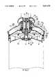
- FIG. 1is a sectional assembly view of a vacuum container of a preferred embodiment while a press plate is not in operation;
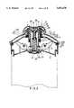
- FIG. 2is a sectional assembly view of a vacuum container of a preferred embodiment while a press plate is pressed downward;
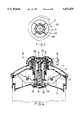
- FIG. 3is a sectional assembly view of a vacuum container of a preferred embodiment while a press plate is pressed down to the utmost;
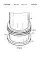
- FIG. 4is a sectional view of a press plate which is pressed down to the utmost
- FIG. 5is a schematic view illustrating an operation of a press plate to extract the air in the vacuum container
- FIG. 6is a sectional assembly view of a vacuum container with another slide block therein;
- FIG. 7is a partially sectional view taken along line 7A--7A in FIG. 4;
- FIG. 8is an elevational view of a retaining ring and a plurality of ribs
- FIG. 9is a sectional view of the first choke ring
- FIG. 10is a sectional view of the second choke ring
- FIG. 11is a sectional view of the third choke ring
- FIG. 12is an elevational view of a cylinder seat with a lower disk and a recess ring
- FIG. 13is an elevational view of a slide block
- FIG. 14is a sectional view taken along line 14A--14A in FIG. 13.
- a vacuum containerhas a vessel 2 and an installed air extraction device covering the vessel 2.
- the installed air extraction devicehas a cap 1, an air extraction device 20 disposed in the cap 1, and an air inlet valve 30 passing through a center of the cap 1.
- the cap 1has an inner cover 10, an outer cover 11, and a hollow interior 12 defined between the inner cover 10 and the outer cover 11.
- An extending sleeve 13extends downward from a periphery edge of the outer cover 11 to enclose an upper rim of the vessel 2.
- a plurality of first vents 100are formed on a center portion of the inner cover 10.
- a plurality of third vents 110are formed on a center portion of the outer cover 11.
- a plurality of grooves 111are formed on the outer cover 11 near the corresponding first vents 100 (as shown in FIGS. 1 and 7).
- An inner sleeve 112extends downward from the center portion of the outer cover 11.
- the air extraction device 20has a hollow press plate 21 disposed on a top of the outer cover 11, a cylinder seat 211 extending downward from the hollow press plate 21, a lower disk 217 disposed at a bottom of the cylinder seat 211, a lining cap 22 flaring downward from the cylinder seat 211 to the extending sleeve 13, a retaining ring 218 surrounding an upper portion of the cylinder seat 211 (as shown in FIGS.
- a first recess ring 214surrounds the cylinder seat 211 (as shown in FIGS. 9 and 12). The first recess ring 214 has a recess to receive a first choke ring 215.
- the first choke ring 215contacts the inner sleeve 112 (as shown in FIG. 9).
- a plurality of first air passages 2140pass through the first recess ring 214.
- a hollow tube 102extends upward from the lower disk 217.
- a first spring 216is disposed between the hollow press plate 21 and the hollow tube 102.
- a plurality of second vents 103are formed on a lower portion of the hollow tube 102.
- a second spring 220is disposed between the outer cover 11 and the lining cap 22 to surround the inner sleeve 112.
- a second recess ring 221is formed in an upper inner periphery of the lining cap 22 (as shown in FIG. 10).
- the second recess ring 221has a recess to receive a second choke ring 222 (as shown in FIG. 10).
- the second choke ring 222contacts the inner sleeve 112 (as shown in FIG. 10).
- a plurality of second air passages 2210pass through the second recess ring 221.
- a third recess ring 223is formed on an outer rim of the lining cap 22.
- the third recess ring 223has a recess to receive a third choke ring 224 (as shown in FIG. 11).
- the third choke ring 224contacts the extending sleeve 13.
- a plurality of third air passages 2230pass through the third recess ring 223.
- Two support plates 230extend upward from the inner cover 10 to support the corresponding slide blocks 23 pivotally (as shown in FIGS. 1, 13 and 14).
- Each of the ribs 212has two first bevels 2120 to form an upper end.
- the ribs 212are inserted in the corresponding grooves 111.
- Each of the guide blocks 213has two second bevels 2130 to form a lower end.
- the hollow press plate 21has a periphery flap 210.
- a check ring 320is disposed beneath the hollow press plate 21.
- the air inlet valve 30has a plug plate 31 disposed in a bottom end of the hollow tube 102 and a push bar 32 passing through the hollow press plate 21 and the check ring 320 to be inserted in the hollow tube 102.
- the check ring 320contacts the first spring 216.
- two support seats 231'extend upward from the inner cover 10 to support the corresponding curved slide blocks 23' pivotally.
- Each of the support s eats 231'has a positioning recess 2310' to receive the corresponding curved slide block 23', respectively.
- the push bar 32is pressed downward in order to open the vacuum container.
- the hollow press plate 21is pressed downward to drive the first spring 216 to move downward and the first choke ring 215 to move downward.
- the first choke ring 215blocks a spacing between the inner sleeve 112 and the first recess ring 214.
- the ribs 212moves downward along the corresponding grooves 111.
- the second end of each of the slide blocks 23moves downward.
- the first end of each of the slide blocks 23moves downward to push the lining cap 22 upward.
- the second choke ring 222blocks a gap between the inner sleeve 112 and the second recess ring 221.
- the third choke ring 224blocks an interval between the extending sleeve 13 and the third recess ring 223.
- the check ring 320blocks a clearance between the hollow press plate 21 and the push bar 32.
- An upward motion of the lining cap 22produces a suction for the air in the vessel 2.
- the air in the vessel 2passes through the first vents 100 to push the plug plate 31 upward,
- the airenters the hollow interior 12 via the second vents 103.
- the plug plate 31plugs the first vents 100 while the vessel 2 is in vacuum.
Landscapes
- Engineering & Computer Science (AREA)
- General Engineering & Computer Science (AREA)
- Mechanical Engineering (AREA)
- Packages (AREA)
- Closures For Containers (AREA)
Abstract
Description
The invention relates to a vacuum container. More particularly, the invention relates to a vacuum container which has an air extraction device to extract the air in the vacuum container very fast.
There are two types of conventional vacuum containers. The first type vacuum container has a separated air extractor. The user has to hold the air extractor while the air extractor is in operation. Since the air extractor should be detached while the air extractor is in operation, the separated air extractor will occupy a room of storage. The second type vacuum container has an installed air extractor. Since the extracted air is confined in a very small interior of the installed air extractor, it will consume a long period of time to extract all the air in the vacuum container completely.
An object of the invention is to provide a vacuum container which has an installed air extraction device to extract the air in the vacuum container very fast.
Another object of the invention is to provide a vacuum container with an installed air extraction device which has a steady center of gravity while operating.
Accordingly, a vacuum container comprises a vessel and an installed air extraction device covering the vessel. The installed air extraction device has a cap, an air extraction device disposed in the cap, and an air inlet valve passing through a center of the cap. The cap has an inner cover, an outer cover, and a hollow interior defined between the inner cover and the outer cover. An extending sleeve extends downward from a periphery edge of the outer cover to enclose an upper rim of the vessel. A plurality of first vents are formed on a center portion of the inner cover. A plurality of third vents are formed on a center portion of the outer cover. A plurality of grooves are formed on the outer cover near the corresponding first vents. An inner sleeve extends downward from the center portion of the outer cover. The air extraction device has a hollow press plate disposed on a top of the outer cover, a cylinder seat extending downward from the hollow press plate, a lower disk disposed at a bottom of the cylinder seat, a lining cap flaring downward from the cylinder seat to the extending sleeve, a retaining ring surrounding an upper portion of the cylinder seat, a plurality of ribs extending upward from the retaining ring to abut a periphery of the cylinder seat, and a plurality of guide blocks disposed beneath the hollow press plate to face the corresponding ribs. Two slide blocks are disposed between the inner cover and the lining cap pivotally. Each of the slide blocks has a first end contacting the lining cap and a second end contacting the lower disk. A first recess ring surrounds the cylinder seat. The first recess ring has a recess to receive a first choke ring. The first choke ring contacts the inner sleeve. A plurality of first air passages pass through the first recess ring. A hollow tube extends upward from the lower disk. A first spring is disposed between the hollow press plate and the hollow tube. A plurality of second vents are formed on a lower portion of the hollow tube. A second spring is disposed between the outer cover and the lining cap to surround the inner sleeve. A second recess ring is formed in an upper inner periphery of the lining cap. The second recess ring has a recess to receive a second choke ring. The second choke ring contacts the inner sleeve. A plurality of second air passages pass through the second recess ring. A third recess ring is formed on an outer rim of the lining cap. The third recess ring has a recess to receive a third choke ring. The third choke ring contacts the extending sleeve. A plurality of third air passages pass through the third recess ring. Two support plates extend upward from the inner cover to support the corresponding slide blocks pivotally. Each of the ribs has two first bevels to form an upper end. The ribs are inserted in the corresponding grooves. Each of the guide blocks has two second bevels to form a lower end. The hollow press plate has a periphery flap. A check ring is disposed beneath the hollow press plate. The air inlet valve has a plug plate disposed in a bottom end of the hollow tube and a push bar passing through the hollow press plate and the check ring to be inserted in the hollow tube. The check ring contacts the first spring. The hollow press plate is pressed downward to drive the first spring to move downward and the first choke ring to move downward. The first choke ring blocks a spacing between the inner sleeve and the first recess ring. The ribs moves downward along the corresponding grooves. The second end of each of the slide blocks moves downward. The first end of each of the slide blocks moves downward to push the lining cap upward. The second choke ring blocks a gap between the inner sleeve and the second recess ring. The third choke ring blocks an interval between the extending sleeve and the third recess ring. The check ring blocks a clearance between the hollow press plate and the push bar. An upward motion of the lining cap produces a suction for the air in the vessel. The air in the vessel passes through the first vents to push the plug plate upward. The air enters the hollow interior via the second vents. The plug plate plugs the first vents while the vessel is in vacuum.
FIG. 1 is a sectional assembly view of a vacuum container of a preferred embodiment while a press plate is not in operation;
FIG. 2 is a sectional assembly view of a vacuum container of a preferred embodiment while a press plate is pressed downward;
FIG. 3 is a sectional assembly view of a vacuum container of a preferred embodiment while a press plate is pressed down to the utmost;
FIG. 4 is a sectional view of a press plate which is pressed down to the utmost;
FIG. 5 is a schematic view illustrating an operation of a press plate to extract the air in the vacuum container;
FIG. 6 is a sectional assembly view of a vacuum container with another slide block therein;
FIG. 7 is a partially sectional view taken alongline 7A--7A in FIG. 4;
FIG. 8 is an elevational view of a retaining ring and a plurality of ribs;
FIG. 9 is a sectional view of the first choke ring;
FIG. 10 is a sectional view of the second choke ring;
FIG. 11 is a sectional view of the third choke ring;
FIG. 12 is an elevational view of a cylinder seat with a lower disk and a recess ring;
FIG. 13 is an elevational view of a slide block; and
FIG. 14 is a sectional view taken alongline 14A--14A in FIG. 13.
Referring to FIGS. 1 to 4, a vacuum container has a vessel 2 and an installed air extraction device covering the vessel 2. The installed air extraction device has a cap 1, anair extraction device 20 disposed in the cap 1, and anair inlet valve 30 passing through a center of the cap 1. The cap 1 has aninner cover 10, anouter cover 11, and ahollow interior 12 defined between theinner cover 10 and theouter cover 11. An extendingsleeve 13 extends downward from a periphery edge of theouter cover 11 to enclose an upper rim of the vessel 2. A plurality offirst vents 100 are formed on a center portion of theinner cover 10. A plurality ofthird vents 110 are formed on a center portion of theouter cover 11. A plurality ofgrooves 111 are formed on theouter cover 11 near the corresponding first vents 100 (as shown in FIGS. 1 and 7). Aninner sleeve 112 extends downward from the center portion of theouter cover 11. Theair extraction device 20 has ahollow press plate 21 disposed on a top of theouter cover 11, acylinder seat 211 extending downward from thehollow press plate 21, alower disk 217 disposed at a bottom of thecylinder seat 211, alining cap 22 flaring downward from thecylinder seat 211 to the extendingsleeve 13, a retainingring 218 surrounding an upper portion of the cylinder seat 211 (as shown in FIGS. 1 and 8), a plurality ofribs 212 extending upward from the retaining ring 218 (as shown in FIG. 8) to abut a periphery of thecylinder seat 211, and a plurality of guide blocks 213 disposed beneath thehollow press plate 21 to face thecorresponding ribs 212. Two slide blocks 23 are disposed between theinner cover 10 and thelining cap 22 pivotally. Each of the slide blocks 23 has a first end contacting thelining cap 22 and a second end contacting thelower disk 217. Afirst recess ring 214 surrounds the cylinder seat 211 (as shown in FIGS. 9 and 12). Thefirst recess ring 214 has a recess to receive afirst choke ring 215. Thefirst choke ring 215 contacts the inner sleeve 112 (as shown in FIG. 9). A plurality offirst air passages 2140 pass through thefirst recess ring 214. Ahollow tube 102 extends upward from thelower disk 217. Afirst spring 216 is disposed between thehollow press plate 21 and thehollow tube 102. A plurality ofsecond vents 103 are formed on a lower portion of thehollow tube 102. Asecond spring 220 is disposed between theouter cover 11 and thelining cap 22 to surround theinner sleeve 112. Asecond recess ring 221 is formed in an upper inner periphery of the lining cap 22 (as shown in FIG. 10). Thesecond recess ring 221 has a recess to receive a second choke ring 222 (as shown in FIG. 10). Thesecond choke ring 222 contacts the inner sleeve 112 (as shown in FIG. 10). A plurality ofsecond air passages 2210 pass through thesecond recess ring 221. Athird recess ring 223 is formed on an outer rim of thelining cap 22. Thethird recess ring 223 has a recess to receive a third choke ring 224 (as shown in FIG. 11). Thethird choke ring 224 contacts the extendingsleeve 13. A plurality ofthird air passages 2230 pass through thethird recess ring 223. Twosupport plates 230 extend upward from theinner cover 10 to support the corresponding slide blocks 23 pivotally (as shown in FIGS. 1, 13 and 14). Each of theribs 212 has twofirst bevels 2120 to form an upper end. Theribs 212 are inserted in thecorresponding grooves 111. Each of the guide blocks 213 has twosecond bevels 2130 to form a lower end. Thehollow press plate 21 has aperiphery flap 210. Acheck ring 320 is disposed beneath thehollow press plate 21. Theair inlet valve 30 has aplug plate 31 disposed in a bottom end of thehollow tube 102 and apush bar 32 passing through thehollow press plate 21 and thecheck ring 320 to be inserted in thehollow tube 102. Thecheck ring 320 contacts thefirst spring 216.
Referring to FIG. 6, two support seats 231' extend upward from theinner cover 10 to support the corresponding curved slide blocks 23' pivotally. Each of the support s eats 231' has a positioning recess 2310' to receive the corresponding curved slide block 23', respectively.
Referring to FIG. 5, thepush bar 32 is pressed downward in order to open the vacuum container.
Referring to FIG. 2, thehollow press plate 21 is pressed downward to drive thefirst spring 216 to move downward and thefirst choke ring 215 to move downward. Thefirst choke ring 215 blocks a spacing between theinner sleeve 112 and thefirst recess ring 214. Theribs 212 moves downward along the correspondinggrooves 111. The second end of each of the slide blocks 23 moves downward. The first end of each of the slide blocks 23 moves downward to push thelining cap 22 upward. Thesecond choke ring 222 blocks a gap between theinner sleeve 112 and thesecond recess ring 221. Thethird choke ring 224 blocks an interval between the extendingsleeve 13 and thethird recess ring 223. Thecheck ring 320 blocks a clearance between thehollow press plate 21 and thepush bar 32. An upward motion of thelining cap 22 produces a suction for the air in the vessel 2. The air in the vessel 2 passes through thefirst vents 100 to push theplug plate 31 upward, The air enters thehollow interior 12 via the second vents 103. Theplug plate 31 plugs thefirst vents 100 while the vessel 2 is in vacuum.
The invention is not limited to the above embodiment but various modification thereof may be made. Further, various changes in form and detail may be made without departing from the scope of the invention.
Claims (2)
1. A vacuum container comprising:
a vessel and an installed air extraction device covering the vessel,
the installed air extraction device having a cap, an air extraction device disposed in the cap, and an air inlet valve passing through a center of the cap,
the cap having an inner cover, an outer cover, and a hollow interior defined between the inner cover and the outer cover,
an extending sleeve extending downward from a periphery edge of the outer cover to enclose an upper rim of the vessel,
a plurality of first vents formed on a center portion of the inner cover,
a plurality of third vents formed on a center portion of the outer cover,
a plurality of grooves formed on the outer cover near the corresponding first vents,
an inner sleeve extending downward from the center portion of the outer cover,
the air extraction device having a hollow press plate disposed on a top of the outer cover, a cylinder seat extending downward from the hollow press plate, a lower disk disposed at a bottom of the cylinder seat, a lining cap flaring downward from the cylinder seat to the extending sleeve, a retaining ring surrounding an upper portion of the cylinder seat, a plurality of ribs extending upward from the retaining ring to abut a periphery of the cylinder seat, and a plurality of guide blocks disposed beneath the hollow press plate to face the corresponding ribs,
two slide blocks disposed between the inner cover and the lining cap pivotally,
each of the slide blocks having a first end contacting the lining cap and a second end contacting the lower disk,
a first recess ring surrounding the cylinder seat,
the first recess ring having a recess to receive a first choke ring,
the first choke ring contacting the inner sleeve,
a plurality of first air passages passing through the first recess ring,
a hollow tube extending upward from the lower disk,
a first spring disposed between the hollow press plate and the hollow tube,
a plurality of second vents formed on a lower portion of the hollow tube,
a second spring disposed between the outer cover and the lining cap to surround the inner sleeve,
a second recess ring formed in an upper inner periphery of the lining cap,
the second recess ring having a recess to receive a second choke ring,
the second choke ring contacting the inner sleeve,
a plurality of second air passages passing through the second recess ring,
a third recess ring formed on an outer rim of the lining cap,
the third recess ring having a recess to receive a third choke ring,
the third choke ring contacting the extending sleeve,
a plurality of third air passages passing through the third recess ring,
two support plates extending upward from the inner cover to support the corresponding slide blocks pivotally,
each of the ribs having two first bevels to form an upper end,
the ribs inserted in the corresponding grooves,
each of the guide blocks having two second bevels to form a lower end,
the hollow press plate having a periphery flap,
a check ring disposed beneath the hollow press plate,
the air inlet valve having a plug plate disposed in a bottom end of the hollow tube and a push bar passing through the hollow press plate and the check ring to be inserted in the hollow tube,
the check ring contacting the first spring, and
wherein the hollow press plate is pressed downward to drive the first spring to move downward and the first choke ring to move downward, the first choke ring blocks a spacing between the inner sleeve and the first recess ring, the ribs moves downward along the corresponding grooves, the second end of each of the slide blocks moves downward, the first end of each of the slide blocks moves downward to push the lining cap upward, the second choke ring blocks a gap between the inner sleeve and the second recess ring, the third choke ring blocks an interval between the extending sleeve and the third recess ring, the check ring blocks a clearance between the hollow press plate and the push bar, an upward motion of the lining cap produces a suction for the air in the vessel, the air in the vessel passes through the first vents to push the plug plate upward, the air enters the hollow interior via the second vents, and the plug plate plugs the first vents while the vessel is in vacuum.
2. A vacuum container as claimed in claim 1, wherein each of said slide blocks is in a curved shape.
Priority Applications (2)
| Application Number | Priority Date | Filing Date | Title |
|---|---|---|---|
| US08/697,488US5651470A (en) | 1996-08-26 | 1996-08-26 | Vacuum container |
| DE29614986UDE29614986U1 (en) | 1996-08-26 | 1996-08-28 | Vacuum container |
Applications Claiming Priority (2)
| Application Number | Priority Date | Filing Date | Title |
|---|---|---|---|
| US08/697,488US5651470A (en) | 1996-08-26 | 1996-08-26 | Vacuum container |
| DE29614986UDE29614986U1 (en) | 1996-08-26 | 1996-08-28 | Vacuum container |
Publications (1)
| Publication Number | Publication Date |
|---|---|
| US5651470Atrue US5651470A (en) | 1997-07-29 |
Family
ID=26059355
Family Applications (1)
| Application Number | Title | Priority Date | Filing Date |
|---|---|---|---|
| US08/697,488Expired - Fee RelatedUS5651470A (en) | 1996-08-26 | 1996-08-26 | Vacuum container |
Country Status (2)
| Country | Link |
|---|---|
| US (1) | US5651470A (en) |
| DE (1) | DE29614986U1 (en) |
Cited By (47)
| Publication number | Priority date | Publication date | Assignee | Title |
|---|---|---|---|---|
| US5806575A (en)* | 1997-04-11 | 1998-09-15 | Tsay; Shiu Chu | Vacuum extractor of a vacuum container |
| US5941391A (en)* | 1997-09-03 | 1999-08-24 | Jury; Dan E. | Vacuum storage system |
| US5957317A (en)* | 1998-06-30 | 1999-09-28 | Lee; Shun-Chich | Evacuation actuating closure for a container |
| US5992666A (en)* | 1998-01-21 | 1999-11-30 | Wu; Mao Sheng | Sealing cap for a vacuum seal container |
| US6035769A (en)* | 1997-04-16 | 2000-03-14 | Hikari Kinzoku Industry Co., Ltd. | Method for preserving cooked food and vacuum sealed preservation container therefor |
| US6044756A (en)* | 1999-08-27 | 2000-04-04 | Chang; Kun Sheng | Vacuum pot capable of showing vacuum status |
| US6131753A (en)* | 1999-05-17 | 2000-10-17 | Lynch; John Berrien | Vacuum jar apparatus |
| US6375024B1 (en)* | 1999-08-19 | 2002-04-23 | Yoon Sik Park | Vacuum apparatus for forming a vacuum in a container |
| US20020124471A1 (en)* | 2001-02-23 | 2002-09-12 | Anderson Curt L. | Reusable vacuum lid |
| US20030047700A1 (en)* | 2001-07-24 | 2003-03-13 | Hiroshi Motonaka | Exhaust valve for a bag |
| WO2003035506A1 (en)* | 2001-10-19 | 2003-05-01 | Fratelli Guzzini S.P.A. | Container for the preservation of products under vacuum |
| US6557462B1 (en)* | 2001-12-28 | 2003-05-06 | Wang Soo Chang | Combined vacuum valve and vacuum indicator |
| US6581641B2 (en)* | 2001-04-05 | 2003-06-24 | Illinois Tool Works Inc. | One-way valve for use with vacuum pump |
| US6619493B2 (en)* | 2002-01-28 | 2003-09-16 | Heng-Te Yang | Sealable container |
| US6675982B2 (en) | 2001-02-23 | 2004-01-13 | Tilia International, Inc. | Lid with a pump/bellows device |
| US20040084450A1 (en)* | 2002-11-05 | 2004-05-06 | Tilia International, Inc. | Canister lid with improved evacuation and vent assembly |
| US20040155041A1 (en)* | 2003-02-11 | 2004-08-12 | Man-Hyun Kwon | Vacuum container to preserve food |
| US6789690B2 (en) | 2002-04-19 | 2004-09-14 | Tilia International, Inc. | Hose direct canister lid |
| US20050061370A1 (en)* | 2003-08-16 | 2005-03-24 | Landen Higer | Vacuum packaging appliance spice rack |
| US20050244293A1 (en)* | 2004-04-28 | 2005-11-03 | Lin Yvonne S | Vacuum canister |
| US20060000733A1 (en)* | 2004-07-02 | 2006-01-05 | Albritton Charles W | Rigid container with vacuum channel walls |
| US7003928B2 (en) | 2002-10-04 | 2006-02-28 | Jcs/Thg, Llc | Appliance for vacuum sealing food containers |
| US7076929B2 (en) | 2002-10-04 | 2006-07-18 | Jcs/Thg, Llc | Appliance for vacuum sealing food containers |
| US7131250B2 (en) | 2002-10-04 | 2006-11-07 | Jcs/Thg, Llp | Appliance for vacuum sealing food containers |
| US20070095713A1 (en)* | 2005-10-27 | 2007-05-03 | Schooley Bruce A | Vacuum storage container |
| US20090101535A1 (en)* | 2007-10-19 | 2009-04-23 | Kuo Chin Hsieh | Vacuum fresh-keeping cover |
| CN100497104C (en)* | 2002-12-27 | 2009-06-10 | 株式会社柏原制袋 | Degassing valve and degassing bag and method for producing degassing bag |
| US20090175747A1 (en)* | 2008-01-09 | 2009-07-09 | Leboeuf William E | Manual evacuation system |
| US20090238702A1 (en)* | 2008-03-20 | 2009-09-24 | Blythe James S | Food storage bag vacuum pump |
| US7967509B2 (en) | 2007-06-15 | 2011-06-28 | S.C. Johnson & Son, Inc. | Pouch with a valve |
| JP5087711B1 (en)* | 2012-04-18 | 2012-12-05 | 株式会社東晃エンジニアリング | Pressure vessel for pressure, pressure vessel for vacuum and pressure vessel for both pressure and vacuum |
| US20130146500A1 (en)* | 2010-01-15 | 2013-06-13 | Yong-Kug Kim | Vacuum generating apparatus and vacuum container provided with the same |
| US20130292291A1 (en)* | 2012-05-04 | 2013-11-07 | To Yan Lui | Vacuumized container box |
| US9321064B2 (en)* | 2010-09-24 | 2016-04-26 | Blake Vanier | Drinking vessel with pump and methods |
| US9510615B2 (en)* | 2004-03-24 | 2016-12-06 | Jeffrey S. Melcher | Vacuum storage apparatus with sliding drawers |
| US20170181558A1 (en)* | 2015-12-24 | 2017-06-29 | Life & Living International Limited | Bottle cover and bottle with the bottle cover |
| US20180273274A1 (en)* | 2017-03-22 | 2018-09-27 | Shin Hung Yih Technology Co., Ltd. | Negative Pressure Storage Container |
| CN109068895A (en)* | 2016-03-13 | 2018-12-21 | 福乐士吉科有限公司 | Vacuum tank, system and method |
| CN109733736A (en)* | 2018-12-28 | 2019-05-10 | 江苏成华能源化工设备有限公司 | A kind of pressure test airtight lid for container |
| US20200359866A1 (en)* | 2019-05-13 | 2020-11-19 | Mosa Solutions, Inc. | Vacuum pump lid for cannisters |
| US11365041B2 (en)* | 2016-07-27 | 2022-06-21 | Hbl Holdings, Llc | Vacuum sealable container with internal pump mechanism |
| US20220227548A1 (en)* | 2019-05-21 | 2022-07-21 | Pacific Market International, Llc | Drink container and leak proof plug lid for use therewith |
| US12060179B2 (en)* | 2022-09-06 | 2024-08-13 | Shanghai Xinqi Electronic Technology Co., Ltd. | Mason jar seal device |
| US20240317478A1 (en)* | 2023-03-23 | 2024-09-26 | Jing-Feng WU | Vacuum container |
| US12209005B2 (en)* | 2022-09-06 | 2025-01-28 | Shanghai Xinqi Electronic Technology Co., Ltd. | Mason jar sealing device |
| US12269724B2 (en)* | 2022-09-06 | 2025-04-08 | Shanghai Xinqi Electronic Technology Co., Ltd. | Mason jar sealing device |
| US12415664B2 (en)* | 2023-08-09 | 2025-09-16 | Universal Trim Supply Co., Ltd. | Cover device |
Families Citing this family (1)
| Publication number | Priority date | Publication date | Assignee | Title |
|---|---|---|---|---|
| KR100436308B1 (en)* | 2001-10-08 | 2004-06-18 | 고려알파라인(주) | bottle cap for vacuum preservation |
Citations (7)
| Publication number | Priority date | Publication date | Assignee | Title |
|---|---|---|---|---|
| US5398811A (en)* | 1994-03-10 | 1995-03-21 | Latella, Jr.; Demetrio A. | Vacuum sealed canister |
| US5406992A (en)* | 1993-04-19 | 1995-04-18 | Jeff Stuebing | Self contained evacuation lid |
| US5469979A (en)* | 1994-10-21 | 1995-11-28 | Chiou; Wen-Nen | Adjustable sealed can |
| US5546997A (en)* | 1993-04-19 | 1996-08-20 | Invental Laboratory, Inc. | Easily-cleaned reusable lid including an evacuating pump |
| US5558243A (en)* | 1994-11-07 | 1996-09-24 | Chiun Pao Enterprise Co., Ltd. | Sealing cap for vacuum containers |
| US5564480A (en)* | 1995-02-24 | 1996-10-15 | Chen; Chen-Hai | Vacuum canister |
| US5564581A (en)* | 1995-08-23 | 1996-10-15 | Pi-Chu Lin | Vacuum canister |
- 1996
- 1996-08-26USUS08/697,488patent/US5651470A/ennot_activeExpired - Fee Related
- 1996-08-28DEDE29614986Upatent/DE29614986U1/ennot_activeExpired - Lifetime
Patent Citations (7)
| Publication number | Priority date | Publication date | Assignee | Title |
|---|---|---|---|---|
| US5406992A (en)* | 1993-04-19 | 1995-04-18 | Jeff Stuebing | Self contained evacuation lid |
| US5546997A (en)* | 1993-04-19 | 1996-08-20 | Invental Laboratory, Inc. | Easily-cleaned reusable lid including an evacuating pump |
| US5398811A (en)* | 1994-03-10 | 1995-03-21 | Latella, Jr.; Demetrio A. | Vacuum sealed canister |
| US5469979A (en)* | 1994-10-21 | 1995-11-28 | Chiou; Wen-Nen | Adjustable sealed can |
| US5558243A (en)* | 1994-11-07 | 1996-09-24 | Chiun Pao Enterprise Co., Ltd. | Sealing cap for vacuum containers |
| US5564480A (en)* | 1995-02-24 | 1996-10-15 | Chen; Chen-Hai | Vacuum canister |
| US5564581A (en)* | 1995-08-23 | 1996-10-15 | Pi-Chu Lin | Vacuum canister |
Cited By (72)
| Publication number | Priority date | Publication date | Assignee | Title |
|---|---|---|---|---|
| US5806575A (en)* | 1997-04-11 | 1998-09-15 | Tsay; Shiu Chu | Vacuum extractor of a vacuum container |
| US6035769A (en)* | 1997-04-16 | 2000-03-14 | Hikari Kinzoku Industry Co., Ltd. | Method for preserving cooked food and vacuum sealed preservation container therefor |
| US5941391A (en)* | 1997-09-03 | 1999-08-24 | Jury; Dan E. | Vacuum storage system |
| US5992666A (en)* | 1998-01-21 | 1999-11-30 | Wu; Mao Sheng | Sealing cap for a vacuum seal container |
| US5957317A (en)* | 1998-06-30 | 1999-09-28 | Lee; Shun-Chich | Evacuation actuating closure for a container |
| US6131753A (en)* | 1999-05-17 | 2000-10-17 | Lynch; John Berrien | Vacuum jar apparatus |
| US6375024B1 (en)* | 1999-08-19 | 2002-04-23 | Yoon Sik Park | Vacuum apparatus for forming a vacuum in a container |
| US6044756A (en)* | 1999-08-27 | 2000-04-04 | Chang; Kun Sheng | Vacuum pot capable of showing vacuum status |
| US6675982B2 (en) | 2001-02-23 | 2004-01-13 | Tilia International, Inc. | Lid with a pump/bellows device |
| US20020124471A1 (en)* | 2001-02-23 | 2002-09-12 | Anderson Curt L. | Reusable vacuum lid |
| US6634384B2 (en)* | 2001-04-05 | 2003-10-21 | Illinois Tool Works Inc. | One-way valve for use with vacuum pump |
| US6581641B2 (en)* | 2001-04-05 | 2003-06-24 | Illinois Tool Works Inc. | One-way valve for use with vacuum pump |
| US20030047700A1 (en)* | 2001-07-24 | 2003-03-13 | Hiroshi Motonaka | Exhaust valve for a bag |
| US6712334B2 (en)* | 2001-07-24 | 2004-03-30 | Taiyo Kagaku Kabushiki Kaisha | Exhaust valve for a bag |
| US20050051551A1 (en)* | 2001-10-19 | 2005-03-10 | Galletti Davide Gianni Mario | Container for the preservation of products under vacuum |
| WO2003035506A1 (en)* | 2001-10-19 | 2003-05-01 | Fratelli Guzzini S.P.A. | Container for the preservation of products under vacuum |
| US6557462B1 (en)* | 2001-12-28 | 2003-05-06 | Wang Soo Chang | Combined vacuum valve and vacuum indicator |
| US6619493B2 (en)* | 2002-01-28 | 2003-09-16 | Heng-Te Yang | Sealable container |
| US6789690B2 (en) | 2002-04-19 | 2004-09-14 | Tilia International, Inc. | Hose direct canister lid |
| EP1506120A4 (en)* | 2002-04-19 | 2005-11-16 | Tilia Int Inc | Hose direct canister lid |
| AU2003230991B2 (en)* | 2002-04-19 | 2008-02-28 | Sunbeam Products, Inc. | Hose direct canister lid |
| US7131250B2 (en) | 2002-10-04 | 2006-11-07 | Jcs/Thg, Llp | Appliance for vacuum sealing food containers |
| US7454884B2 (en) | 2002-10-04 | 2008-11-25 | Sunbeam Products, Inc. | Appliance for vacuum sealing food containers |
| US7401452B2 (en) | 2002-10-04 | 2008-07-22 | Sunbeam Products, Inc. | Appliance for vacuum sealing food containers |
| US7231753B2 (en) | 2002-10-04 | 2007-06-19 | Sunbeam Products, Inc. | Appliance for vacuum sealing food containers |
| US7003928B2 (en) | 2002-10-04 | 2006-02-28 | Jcs/Thg, Llc | Appliance for vacuum sealing food containers |
| US7076929B2 (en) | 2002-10-04 | 2006-07-18 | Jcs/Thg, Llc | Appliance for vacuum sealing food containers |
| US20040084450A1 (en)* | 2002-11-05 | 2004-05-06 | Tilia International, Inc. | Canister lid with improved evacuation and vent assembly |
| US7048136B2 (en) | 2002-11-05 | 2006-05-23 | Tilia International, Inc. | Canister lid with improved evacuation and vent assembly |
| CN100497104C (en)* | 2002-12-27 | 2009-06-10 | 株式会社柏原制袋 | Degassing valve and degassing bag and method for producing degassing bag |
| US6994227B2 (en)* | 2003-02-11 | 2006-02-07 | Man-Hyun Kwon | vacuum container to preserve food |
| US20040155041A1 (en)* | 2003-02-11 | 2004-08-12 | Man-Hyun Kwon | Vacuum container to preserve food |
| US20050061370A1 (en)* | 2003-08-16 | 2005-03-24 | Landen Higer | Vacuum packaging appliance spice rack |
| US9510615B2 (en)* | 2004-03-24 | 2016-12-06 | Jeffrey S. Melcher | Vacuum storage apparatus with sliding drawers |
| US7296598B2 (en) | 2004-04-28 | 2007-11-20 | Wilton Industries, Inc. | Vacuum canister |
| US20050244293A1 (en)* | 2004-04-28 | 2005-11-03 | Lin Yvonne S | Vacuum canister |
| US20060000733A1 (en)* | 2004-07-02 | 2006-01-05 | Albritton Charles W | Rigid container with vacuum channel walls |
| US7931052B2 (en) | 2005-10-27 | 2011-04-26 | Schooley Bruce A | Vacuum storage container |
| US20070095713A1 (en)* | 2005-10-27 | 2007-05-03 | Schooley Bruce A | Vacuum storage container |
| US7967509B2 (en) | 2007-06-15 | 2011-06-28 | S.C. Johnson & Son, Inc. | Pouch with a valve |
| US8113246B2 (en)* | 2007-10-19 | 2012-02-14 | Kuo Chin Hsieh | Vacuum fresh-keeping cover |
| US20090101535A1 (en)* | 2007-10-19 | 2009-04-23 | Kuo Chin Hsieh | Vacuum fresh-keeping cover |
| US8192182B2 (en) | 2008-01-09 | 2012-06-05 | S.C. Johnson Home Storage, Inc. | Manual evacuation system |
| US20090175747A1 (en)* | 2008-01-09 | 2009-07-09 | Leboeuf William E | Manual evacuation system |
| WO2009117026A1 (en)* | 2008-03-20 | 2009-09-24 | Pactiv Corporation | Food storage bag vacuum pump |
| US20090238702A1 (en)* | 2008-03-20 | 2009-09-24 | Blythe James S | Food storage bag vacuum pump |
| US8740591B2 (en)* | 2008-03-20 | 2014-06-03 | Reynolds Consumer Products LLC | Food storage bag vacuum pump |
| US9096365B2 (en)* | 2010-01-15 | 2015-08-04 | Yong-Kug Kim | Vacuum generating apparatus and vacuum container provided with the same |
| US20130146500A1 (en)* | 2010-01-15 | 2013-06-13 | Yong-Kug Kim | Vacuum generating apparatus and vacuum container provided with the same |
| US9321064B2 (en)* | 2010-09-24 | 2016-04-26 | Blake Vanier | Drinking vessel with pump and methods |
| JP5087711B1 (en)* | 2012-04-18 | 2012-12-05 | 株式会社東晃エンジニアリング | Pressure vessel for pressure, pressure vessel for vacuum and pressure vessel for both pressure and vacuum |
| US20130292291A1 (en)* | 2012-05-04 | 2013-11-07 | To Yan Lui | Vacuumized container box |
| US8936169B2 (en)* | 2012-05-04 | 2015-01-20 | To Yan Lui | Vacuumized container box |
| US20170181558A1 (en)* | 2015-12-24 | 2017-06-29 | Life & Living International Limited | Bottle cover and bottle with the bottle cover |
| US10342371B2 (en)* | 2015-12-24 | 2019-07-09 | Life & Living International Limited | Bottle cover and bottle with the bottle cover |
| CN109068895A (en)* | 2016-03-13 | 2018-12-21 | 福乐士吉科有限公司 | Vacuum tank, system and method |
| US20190084749A1 (en)* | 2016-03-13 | 2019-03-21 | Freshkeep Ltd. | Vacuum container, system and method |
| US11117730B2 (en)* | 2016-03-13 | 2021-09-14 | Freshkeep Ltd. | Vacuum container, system and method |
| CN109068895B (en)* | 2016-03-13 | 2021-10-01 | 福乐士吉科有限公司 | Vacuum vessel, system and method |
| US11970328B2 (en) | 2016-07-27 | 2024-04-30 | Hbl Holdings, Llc | Vacuum sealable container with internal pump mechanism |
| US11365041B2 (en)* | 2016-07-27 | 2022-06-21 | Hbl Holdings, Llc | Vacuum sealable container with internal pump mechanism |
| US20180273274A1 (en)* | 2017-03-22 | 2018-09-27 | Shin Hung Yih Technology Co., Ltd. | Negative Pressure Storage Container |
| US10138046B2 (en)* | 2017-03-22 | 2018-11-27 | Shin Hung Yih Technology Co., Ltd. | Negative pressure storage container |
| CN109733736A (en)* | 2018-12-28 | 2019-05-10 | 江苏成华能源化工设备有限公司 | A kind of pressure test airtight lid for container |
| US20200359866A1 (en)* | 2019-05-13 | 2020-11-19 | Mosa Solutions, Inc. | Vacuum pump lid for cannisters |
| US20220227548A1 (en)* | 2019-05-21 | 2022-07-21 | Pacific Market International, Llc | Drink container and leak proof plug lid for use therewith |
| US12060179B2 (en)* | 2022-09-06 | 2024-08-13 | Shanghai Xinqi Electronic Technology Co., Ltd. | Mason jar seal device |
| US12209005B2 (en)* | 2022-09-06 | 2025-01-28 | Shanghai Xinqi Electronic Technology Co., Ltd. | Mason jar sealing device |
| US12269724B2 (en)* | 2022-09-06 | 2025-04-08 | Shanghai Xinqi Electronic Technology Co., Ltd. | Mason jar sealing device |
| US20240317478A1 (en)* | 2023-03-23 | 2024-09-26 | Jing-Feng WU | Vacuum container |
| US12391454B2 (en)* | 2023-03-23 | 2025-08-19 | Jing-Feng WU | Vacuum container |
| US12415664B2 (en)* | 2023-08-09 | 2025-09-16 | Universal Trim Supply Co., Ltd. | Cover device |
Also Published As
| Publication number | Publication date |
|---|---|
| DE29614986U1 (en) | 1997-01-09 |
Similar Documents
| Publication | Publication Date | Title |
|---|---|---|
| US5651470A (en) | Vacuum container | |
| US5405038A (en) | Vacuum food container device | |
| US5370272A (en) | Dispenser for a liquid to pasty product and subplate for a dispenser of this kind | |
| US5535455A (en) | Sink strainer for garbage disposal unit | |
| CN220608050U (en) | Push type quick-opening cup with one-key cover for exhausting | |
| JP3036320U (en) | Vacuum container extraction device | |
| JPS60131536U (en) | container cap | |
| JPS5817566Y2 (en) | Pneumatic thermos flask | |
| CN2437267Y (en) | Cover means of vacuum bottle | |
| JPH0635560A (en) | Switch device | |
| JPS6035447Y2 (en) | air pot lid | |
| JPS6339491Y2 (en) | ||
| JPS589539Y2 (en) | A flat container with a removable inner plate. | |
| KR200257234Y1 (en) | cork structure for thermos-battle | |
| KR200230927Y1 (en) | A case of draw out same time for matter large | |
| KR950003357Y1 (en) | Automatic punching device for outlet hole of Takju bottle cap | |
| JPH1199075A (en) | Beverage container | |
| JPS5916041Y2 (en) | Pots for using air pressure | |
| JP3031431U (en) | Sealed can for storage | |
| CN207722142U (en) | A kind of fragrant atmosphere diffuser being easily changed fragrant atmosphere product | |
| JP3041015U (en) | Push-out writing instrument | |
| JPS5921712Y2 (en) | Pots for using air pressure | |
| JPS6451041U (en) | ||
| JP3701479B2 (en) | Double cylinder type plunger pump | |
| JPH056933Y2 (en) |
Legal Events
| Date | Code | Title | Description |
|---|---|---|---|
| REMI | Maintenance fee reminder mailed | ||
| LAPS | Lapse for failure to pay maintenance fees | ||
| FP | Expired due to failure to pay maintenance fee | Effective date:20010729 | |
| STCH | Information on status: patent discontinuation | Free format text:PATENT EXPIRED DUE TO NONPAYMENT OF MAINTENANCE FEES UNDER 37 CFR 1.362 |