US5650071A - Technique for priming and recirculating fluid through a dialysis machine to prepare the machine for use - Google Patents
Technique for priming and recirculating fluid through a dialysis machine to prepare the machine for useDownload PDFInfo
- Publication number
- US5650071A US5650071AUS08/481,755US48175595AUS5650071AUS 5650071 AUS5650071 AUS 5650071AUS 48175595 AUS48175595 AUS 48175595AUS 5650071 AUS5650071 AUS 5650071A
- Authority
- US
- United States
- Prior art keywords
- dialyzer
- arterial
- sterile solution
- venous
- blood
- Prior art date
- Legal status (The legal status is an assumption and is not a legal conclusion. Google has not performed a legal analysis and makes no representation as to the accuracy of the status listed.)
- Expired - Lifetime
Links
Images


Classifications
- A—HUMAN NECESSITIES
- A61—MEDICAL OR VETERINARY SCIENCE; HYGIENE
- A61M—DEVICES FOR INTRODUCING MEDIA INTO, OR ONTO, THE BODY; DEVICES FOR TRANSDUCING BODY MEDIA OR FOR TAKING MEDIA FROM THE BODY; DEVICES FOR PRODUCING OR ENDING SLEEP OR STUPOR
- A61M1/00—Suction or pumping devices for medical purposes; Devices for carrying-off, for treatment of, or for carrying-over, body-liquids; Drainage systems
- A61M1/36—Other treatment of blood in a by-pass of the natural circulatory system, e.g. temperature adaptation, irradiation ; Extra-corporeal blood circuits
- A61M1/3621—Extra-corporeal blood circuits
- A61M1/3643—Priming, rinsing before or after use
- A—HUMAN NECESSITIES
- A61—MEDICAL OR VETERINARY SCIENCE; HYGIENE
- A61M—DEVICES FOR INTRODUCING MEDIA INTO, OR ONTO, THE BODY; DEVICES FOR TRANSDUCING BODY MEDIA OR FOR TAKING MEDIA FROM THE BODY; DEVICES FOR PRODUCING OR ENDING SLEEP OR STUPOR
- A61M1/00—Suction or pumping devices for medical purposes; Devices for carrying-off, for treatment of, or for carrying-over, body-liquids; Drainage systems
- A61M1/36—Other treatment of blood in a by-pass of the natural circulatory system, e.g. temperature adaptation, irradiation ; Extra-corporeal blood circuits
- A61M1/3621—Extra-corporeal blood circuits
- A61M1/3622—Extra-corporeal blood circuits with a cassette forming partially or totally the blood circuit
- A61M1/36225—Extra-corporeal blood circuits with a cassette forming partially or totally the blood circuit with blood pumping means or components thereof
- A—HUMAN NECESSITIES
- A61—MEDICAL OR VETERINARY SCIENCE; HYGIENE
- A61M—DEVICES FOR INTRODUCING MEDIA INTO, OR ONTO, THE BODY; DEVICES FOR TRANSDUCING BODY MEDIA OR FOR TAKING MEDIA FROM THE BODY; DEVICES FOR PRODUCING OR ENDING SLEEP OR STUPOR
- A61M1/00—Suction or pumping devices for medical purposes; Devices for carrying-off, for treatment of, or for carrying-over, body-liquids; Drainage systems
- A61M1/36—Other treatment of blood in a by-pass of the natural circulatory system, e.g. temperature adaptation, irradiation ; Extra-corporeal blood circuits
- A61M1/3621—Extra-corporeal blood circuits
- A61M1/3622—Extra-corporeal blood circuits with a cassette forming partially or totally the blood circuit
- A61M1/36226—Constructional details of cassettes, e.g. specific details on material or shape
- A61M1/362262—Details of incorporated reservoirs
- A—HUMAN NECESSITIES
- A61—MEDICAL OR VETERINARY SCIENCE; HYGIENE
- A61M—DEVICES FOR INTRODUCING MEDIA INTO, OR ONTO, THE BODY; DEVICES FOR TRANSDUCING BODY MEDIA OR FOR TAKING MEDIA FROM THE BODY; DEVICES FOR PRODUCING OR ENDING SLEEP OR STUPOR
- A61M1/00—Suction or pumping devices for medical purposes; Devices for carrying-off, for treatment of, or for carrying-over, body-liquids; Drainage systems
- A61M1/36—Other treatment of blood in a by-pass of the natural circulatory system, e.g. temperature adaptation, irradiation ; Extra-corporeal blood circuits
- A61M1/3621—Extra-corporeal blood circuits
- A61M1/3622—Extra-corporeal blood circuits with a cassette forming partially or totally the blood circuit
- A61M1/36226—Constructional details of cassettes, e.g. specific details on material or shape
- A61M1/362266—Means for adding solutions or substances to the blood
- A—HUMAN NECESSITIES
- A61—MEDICAL OR VETERINARY SCIENCE; HYGIENE
- A61M—DEVICES FOR INTRODUCING MEDIA INTO, OR ONTO, THE BODY; DEVICES FOR TRANSDUCING BODY MEDIA OR FOR TAKING MEDIA FROM THE BODY; DEVICES FOR PRODUCING OR ENDING SLEEP OR STUPOR
- A61M1/00—Suction or pumping devices for medical purposes; Devices for carrying-off, for treatment of, or for carrying-over, body-liquids; Drainage systems
- A61M1/36—Other treatment of blood in a by-pass of the natural circulatory system, e.g. temperature adaptation, irradiation ; Extra-corporeal blood circuits
- A61M1/3621—Extra-corporeal blood circuits
- A61M1/3643—Priming, rinsing before or after use
- A61M1/3644—Mode of operation
- A61M1/3646—Expelling the residual body fluid after use, e.g. back to the body
- A—HUMAN NECESSITIES
- A61—MEDICAL OR VETERINARY SCIENCE; HYGIENE
- A61M—DEVICES FOR INTRODUCING MEDIA INTO, OR ONTO, THE BODY; DEVICES FOR TRANSDUCING BODY MEDIA OR FOR TAKING MEDIA FROM THE BODY; DEVICES FOR PRODUCING OR ENDING SLEEP OR STUPOR
- A61M1/00—Suction or pumping devices for medical purposes; Devices for carrying-off, for treatment of, or for carrying-over, body-liquids; Drainage systems
- A61M1/36—Other treatment of blood in a by-pass of the natural circulatory system, e.g. temperature adaptation, irradiation ; Extra-corporeal blood circuits
- A61M1/3621—Extra-corporeal blood circuits
- A61M1/3643—Priming, rinsing before or after use
- A61M1/3644—Mode of operation
- A61M1/3647—Mode of operation with recirculation of the priming solution
- A—HUMAN NECESSITIES
- A61—MEDICAL OR VETERINARY SCIENCE; HYGIENE
- A61M—DEVICES FOR INTRODUCING MEDIA INTO, OR ONTO, THE BODY; DEVICES FOR TRANSDUCING BODY MEDIA OR FOR TAKING MEDIA FROM THE BODY; DEVICES FOR PRODUCING OR ENDING SLEEP OR STUPOR
- A61M2205/00—General characteristics of the apparatus
- A61M2205/12—General characteristics of the apparatus with interchangeable cassettes forming partially or totally the fluid circuit
- A61M2205/123—General characteristics of the apparatus with interchangeable cassettes forming partially or totally the fluid circuit with incorporated reservoirs
- A—HUMAN NECESSITIES
- A61—MEDICAL OR VETERINARY SCIENCE; HYGIENE
- A61M—DEVICES FOR INTRODUCING MEDIA INTO, OR ONTO, THE BODY; DEVICES FOR TRANSDUCING BODY MEDIA OR FOR TAKING MEDIA FROM THE BODY; DEVICES FOR PRODUCING OR ENDING SLEEP OR STUPOR
- A61M39/00—Tubes, tube connectors, tube couplings, valves, access sites or the like, specially adapted for medical use
- A61M39/10—Tube connectors; Tube couplings
Definitions
- the present inventionrelates to a new and improved dialysis system and technique for automatically priming and recirculating fluid through a dialyzer and a disposable blood tubing set which connects a patient to a dialysis machine.
- This inventionis related to the inventions described in U.S. patent applications for Technique for Using a Dialysis Machine to Disinfect a Blood Tubing Set, Ser. No. 08/481,754 and Technique For Automatically Preparing a Dialysis Machine at a Predetermined Date and Time, Ser. No. 08/481,754 both of which were filed concurrently therewith. Both of these applications are assigned to the assignee hereof. The disclosures of these applications are further incorporated herein by this reference.
- a dialysis systemis used as a substitute for the natural kidney functions of a human body.
- the dialysis systemcleans the blood of the natural accumulation of bodily wastes by separating the wastes from the blood outside or extracorporeally of the body. The separated wastes are discharged and the cleansed blood is returned to the body.
- the dialysis systemconsists of a dialysis machine, a dialyzer, a disposable blood tubing set and a supply of chemicals for producing a dialysate solution used within the dialyzer.
- the dialyzeris used with the dialysis machine to separate the wastes from the blood.
- the dialyzerincludes a porous membrane located within a closed housing which effectively separates the housing into a blood compartment and a dialysate or filtrate compartment.
- the blood removed from the patientflows through the disposable blood tubing set and the blood side of the dialyzer.
- the dialysate solution prepared from the chemicalsis passed through the dialysate side of the dialyzer.
- the wastes from the bloodpass through the membrane by osmosis, ionic transfer or fluid transport into the dialysate and, depending upon the type of dialysis treatment, desirable components from the dialysate may pass in the opposite direction through the membrane and into the blood.
- the transfer of the wastes into the dialysatecleanses the blood while allowing the desired components from the dialysate to enter the bloodstream.
- the transfer of blood between the patient and the dialyzeroccurs within a disposable blood tubing set.
- the blood tubing set and the dialyzerrepresent a closed extracorporeal path through which the patient's blood travels.
- the blood tubing setincludes an arterial line connected to an arterial reservoir for drawing blood from a patient, a venous line connected to a venous reservoir for returning blood to the patient, and a number of other lines for connecting a pump and the dialyzer between the arterial and venous reservoirs.
- bothmust be primed with a sterile saline solution to remove air from the extracorporeal circuit.
- the saline solutionis recirculated through the blood tubing set and the dialyzer to produce a stabilized flow and remove additional trapped air from within the extracorporeal circuit.
- the priming and recirculating processalso serves to clean the dialyzer and flush the dialyzer membrane of any debris or chemicals remaining from a prior use.
- a patientreuses the same dialyzer for subsequent dialysis treatments, that dialyzer must be cleaned with a disinfectant or sterilant solution.
- the sterilantitself must be cleaned from the dialyzer prior to each dialysis treatment.
- Such a cleaning procedureeffectively takes place when the dialyzer undergoes the priming and recirculating process discussed above.
- the dialyzeris flushed with saline solution which removes a majority of the sterilant.
- the dialysis machinecan be commanded to remove or "pull" a predetermined flow of saline directly from the dialyzer.
- This predetermined flowcorresponds to "pulling off" a predetermined amount of fluid (or weight) from a patient during dialysis, and is commonly referred to as “ultrafiltration.” Removing saline by ultrafiltration during recirculation of the saline solution thus allows the remaining sterilant within the dialyzer to be removed as it mixes with the saline. The saline that is removed by ultrafiltration is replenished from a saline source connected to the extracorporeal circuit so that no additional air is added to the extracorporeal circuit during recirculation.
- a typical priming sequence on a conventional dialysis machinerequires that the operator connect the outlet of the dialysis machine (i.e., the venous line) to a saline source and then operate the dialysis machine in reverse to fill the extracorporeal circuit with saline.
- the priming solutionpasses through the dialyzer and, in light of the reverse flow, exits the extracorporeal circuit through the dialysis machine's input line (i.e., the arterial line) which the operator connects to a waste basin or drain to dispose of the priming solution.
- the initial priming solutionis discarded because it may contain relatively large quantities of sterilant flushed from the dialyzer when the dialyzer is sterilized and reused following a previous dialysis treatment.
- the operatormust disconnect the venous and arterial lines of the blood tubing set from the saline source and waste basin, respectively, and then connect the venous and arterial lines together (i.e., short circuiting the patient).
- the operatorthen switches the dialysis machine from its reverse operation and operates the machine normally to recirculate the saline solution through the extracorporeal circuit.
- the operatormust further connect the saline source to a different portion of the circuit so that additional saline may be supplied to replace the saline removed by ultrafiltration during recirculation.
- One of the significant aspects of the present inventionpertains to a new method of priming and recirculating sterile fluid through an extracorporeal circuit of a dialysis machine without requiring that a dialysis machine operator modify the configuration of the dialysis machine between the separate steps of priming and recirculating.
- Another significant aspect of the present inventionrelates to freeing a dialysis machine operator to attend other duties while the dialysis machine automatically primes and recirculates sterile fluid through the extracorporeal circuit prior to connecting the dialysis machine to a patient.
- a further significant aspect of the present inventionrelates to providing a method of priming and recirculating a dialysis machine which consistently follows specific priming and recirculation parameters established by a hospital or clinic, and which is not subject to human error after the priming and recirculating process has been initiated.
- a further significant aspect of the present inventionrelates to conserving the sterile solution used to prime the extracorporeal circuit and which is recirculated through the circuit after the circuit has been initially primed.
- the present inventionmay be generally summarized as a method of setting up a dialysis machine having a blood pump, a dialyzer, and a blood tubing set which includes an arterial line for drawing blood from a patient, an arterial reservoir for storing the blood received from the patient, a venous reservoir for storing the blood pumped from the arterial reservoir through the dialyzer, and a venous line for returning the blood from the venous reservoir to the patient.
- the dialysis machine incorporating the present inventionfurther includes a connector adapted to connect the arterial line and the venous line to a waste line leading to a waste drain, and a waste valve positioned along the waste line between the connector and the waste drain.
- the connectoris preferably one element of the disposable blood tubing set.
- the waste valvemay be selectively opened and closed to drain fluid from either the arterial line or the venous line (when the waste valve is opened) and to transfer fluid between the arterial and venous lines through the connector (when the waste valve is closed).
- the dialysis machinecan automatically complete both the priming and the recirculation procedure without the assistance of the dialysis machine operator.
- the operatoris required to connect a source of sterile fluid (e.g., a saline bag) to the blood tubing set, and connect the arterial and venous lines to the waste line via the connector, before commanding the dialysis machine to begin the priming and recirculating process.
- a source of sterile fluide.g., a saline bag
- the process of priming and recirculating fluid through the extracorporeal circuitpreferably includes the following steps: closing an arterial clamp on the arterial line to prevent fluid from filling the arterial line; filling the arterial reservoir with a sterile solution; opening the arterial clamp and the waste valve to fill the arterial line with sterile solution from the arterial reservoir and to allow some amount of the sterile solution within the arterial line to drain through the connector and down the waste drain past the open waste valve; closing the arterial clamp to preserve the sterile solution within the arterial line; opening a venous clamp on the venous line and running the pump in a forward direction to draw sterile solution from the arterial reservoir through the dialyzer and the venous reservoir and to allow the sterile solution to drain through the venous line and the connector and down the waste drain past the open waste valve; closing the waste valve, opening the arterial clamp and running the pump backwards to circulate the sterile solution backwards through the dialyzer and the blood tubing set to remove air from the dialyzer; and running the pump forward to recirculate
- fluidmay be drawn directly from the dialyzer while the sterile solution is being recirculated through the dialyzer and the blood tubing set.
- the above stepsare preferably controlled automatically by the dialysis machine, although one or more of the initial steps may be performed manually by the dialysis machine operator while still remaining within the scope of the present invention.
- the substantially automatic control of the priming and recirculating processboth frees the dialysis machine operator to attend to other responsibilities and reduces the potential for errors by the operator. Additionally, the automatic nature of the set-up process provides a consistently prepared dialysis machine and typically utilizes less sterile saline solution than manual priming and recirculation procedures.
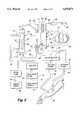
- FIG. 1is a perspective view of a dialysis machine which incorporates the present invention.
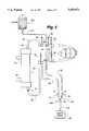
- FIG. 2is a generalized view illustrating a dialyzer, an extracorporeal blood flow path from a patient through the dialyzer, and a dialysate flow path through the dialyzer, as are present during treatment of a patient with the dialysis machine shown in FIG. 1.
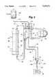
- FIGS. 3-7generally illustrate a dialyzer connected to a blood tubing set which together define the extracorporeal flow path shown in FIG. 2, each of FIGS. 3-7 showing a different stage within a priming and recirculating process which prepares the dialysis machine shown in FIG. 1 for use with a patient.
- FIG. 8is a generalized section view of a connector of the present invention connecting an arterial line and a venous line to a waste port on the dialysis machine shown in FIG. 1.
- the dialysis machine 30includes an enclosure 32 to which are attached, or within which are housed, those functional devices and components of the dialysis machine 30 which are generally illustrated in FIG. 2.
- the enclosure 30also includes a conventional input/output ("I/O") device for controlling the machine 30, such as a touch-screen monitor 33 as shown in FIG. 1.
- I/Oinput/output
- the dialysis machine 30includes at least one blood pump 34 which controls the flow of blood from a patient 36.
- An arterial line or tubing 38is connected through an arterial clamp 40 to a blood handling cartridge 42.
- the blood handling cartridge 42is normally retained behind a door 44 (FIG. 1) of the machine 30 when used, thus the blood handling cartridge 42 is not shown in FIG. 1.
- the blood pump 34also is located behind the door 44 adjacent to the cartridge 42.
- the blood pump 34 in dialysis machinesis typically a peristaltic pump.
- Blood from the patient 36flows through an extracorporeal circuit when the arterial clamp 40 is open and the blood pump 34 draws blood from the patient 36.
- the bloodpasses through the arterial line 38 and into an arterial reservoir 46 of the cartridge 42.
- the blood pump 34draws blood from the arterial reservoir 46 through a pump header 48 which is squeezed or pinched by a rotating rotor 49 against a stationary raceway 50, in the typical manner of peristaltic pumps.
- the blood within the pump header 48 which is rotationally in front of the rotor 49is propelled through the pump header 48 and into a manifold 51 of the cartridge 42.
- a tubing 52conducts the blood from the manifold 51 of the cartridge 42 into a blood inlet 53 of a conventional dialyzer 54.
- a micro-porous membrane or other type of dialysis medium 56divides the interior of the dialyzer 54 into a blood chamber 58 and a dialysate chamber 60.
- the dialyzer 54As the patient's blood passes through the dialyzer 54, the waste products within the blood pass through the medium 56 where they mix with the dialysate in the chamber 60.
- the cleansed bloodthen exits the dialyzer 54 through a blood outlet 61 and is then transferred through a tubing 62 to an inlet 63 of a venous reservoir 64 of the cartridge 42. Any air which might have been unintentionally introduced into the blood is collected and removed while the blood is in the venous reservoir 64.
- a venous blood pump similar to the arterial blood pump 34may be located along the venous line 66 to assist in returning the blood to the patient 36. If employed, the venous blood pump is positioned behind a second door 68 as shown in FIG. 1.
- the bloodflows through the venous line 66 to an air detector 70.
- the air detector 70derives signals related to the quantity of air, if any, remaining in the venous line If an excessive or dangerous amount of air is present, a venous line clamp 72 will immediately close and the blood pump 34 will stop to terminate the flow of blood through the venous line 66 before the detected air reaches the patient 36.
- the enclosure 32 of the dialysis machine 30also encloses the various elements of a dialysate flow path, shown in abbreviated form in FIG. 2.
- the elements of the dialysate flow pathinclude a number of different valves (most of which are not shown) and a dialysate pump 74 which draws dialysate from a container or from an internal supply 76 of dialysate which the dialysis machine 30 has prepared from appropriate chemicals and a supply of purified water.
- the dialysate pump 74draws the dialysate from the supply 76 and delivers the dialysate through a dialysate supply tubing or line 78 to an inlet 79 of the dialysate chamber 60 of the dialyzer 54.
- the dialysateflows past the medium 56 where it absorbs the waste products from the blood in the blood chamber 58. Any beneficial components within the dialysate which are desired to be transferred to the blood pass through the medium 56 and enter the blood in the blood chamber 58.
- Dialysate containing the waste productsexits the dialysate chamber 60 through an outlet 81 and is removed from the dialyzer 54 through a dialysate waste tubing or line 82 by operation of a drain pump 84.
- the drain pump 84may be operated at a lesser volumetric pumping rate compared to the volumetric pumping rate of the dialysate pump 74 when it is desired to transfer components from the dialysate into the blood by fluid transport within the dialyzer 54.
- the drain pump 84is operated at a greater volumetric pumping rate compared to the volumetric pumping rate of the dialysate pump 74 when it is desired to remove fluid components from the blood by fluid transport. Both of these flow control techniques are known as ultrafiltration and are well known dialysis treatments.
- the dialysate removed from the dialyzer 54is delivered through the waste tubing 82 to a waste drain 86.
- the waste drain 86may be a separate container which receives the used dialysate and accumulated waste products, or it may simply be a drain to a public sewer.
- the various valves and pumps which control the dialysate flow pathare referred to generally as the dialysate hydraulics.
- an anticoagulantsuch as heparin into the extracorporeal flow path.
- the typical approach to injecting the anticoagulantis to slowly deliver it from a syringe 89.
- a plunger 90 of the syringeis slowly and controllably displaced into the syringe 89 by a linear driver mechanism (not shown), which is typically referred to as the anticoagulant pump.
- Anticoagulant from the syringe 89is introduced into the manifold 51 of the cartridge 42 through a tubing 92 connected to the syringe as shown in FIG. 2.
- the anticoagulant pumpis controlled to deliver the desired amount of anticoagulant during the dialysis treatment by the degree to which the anticoagulant pump moves the plunger 90 into the syringe 89 over a given time period.
- Tubings 94 and 96are respectively connected to the arterial reservoir 46 and venous reservoir 64 of the cartridge 42 as shown in FIG. 2. Clamps or caps (not shown) are connected to the ends of the tubings 94 and 96 to selectively vent accumulated air from the reservoirs 46 and 64.
- a saline tubing 98is also connected to the arterial reservoir 46 so that saline may be directly administered to the patient during treatment in case of low blood pressure.
- a pole 100 for supporting a conventional saline bagis attached to a side of the enclosure 32, as shown in FIG. 1. Additionally, medicines or other additives may be introduced into the blood through the access tubing 94 during treatment.
- the reservoirs 46 and 64 and the manifold 51 of the blood handling cartridge 42, together with the tubes 38, 48, 52, 62 and 66,are collectively referred to as a blood tubing set ("BTS").
- BTSblood tubing set
- the BTSis disposable and is typically discarded after each dialysis treatment.
- the dialyzer 54is termed a disposable product, although it is not uncommon for a dialyzer to be reused with a single patient. A dialyzer will typically be reused by a patient who regularly visits the same clinic for dialysis treatments. Following each treatment, the dialyzer is cleaned with a sterilant and is then stored until the patient's next visit to the clinic. The dialyzer must then be thoroughly cleaned before use to ensure that the sterilant is not transferred to the patient's bloodstream during the next dialysis treatment.
- the disposable BTS and the dialyzer 54(regardless of whether the dialyzer is new or "used") must be attached to a dialysis machine 30 and prepared for a patient's use by an operator. While the disposable BTS is sterile and thus does not need to be cleaned, the BTS and the dialyzer 54 must be primed with a sterile saline solution to remove the air from the extracorporeal circuit. In addition to flushing the dialyzer 54 with saline solution during priming, the saline solution must be recirculated through the dialyzer for a predetermined period of time to ensure that substantially all of the sterilant or other chemical debris within the dialyzer has been removed.
- This recirculation processalso establishes a stable flow within the extracorporeal circuit and ensures that any remaining air within the circuit has been removed before the patient is connected to the machine 30.
- the arterial line 38is attached to the patient and the patient's blood is drawn through the circuit.
- the venous line 66is connected to the waste drain 86 to dispose of the used saline solution and, at the point the patient's blood has displaced all the saline within the circuit, the venous line is connected to the patient, as shown in FIG. 2.
- the automatic nature of the present inventionallows a dialysis machine operator to attach the BTS and the dialyzer 54 to the dialysis machine 30 and make a small number of other connections to the BTS prior to commanding the machine 30 to perform both the priming and the recirculation procedures discussed above. Upon the conclusion of the recirculation procedure, the machine 30 will place itself in a steady state mode and provide an indication that it is ready for connection to a patient.
- the BTSincludes a Y- or T-shaped connector 102 (FIG. 8) which is adapted to commonly connect the ends of the arterial line 38 and the venous line 66 to a waste line 104 which, in turn, is connected to the waste basin or drain 86.
- the waste line 104is considered to be separate from the waste tubing 82 (FIG. 2) leading from the outlet 81 of the dialyzer 54, although one skilled in the art could utilize a single waste tubing for both purposes.
- a waste valve 106is used to selectively open and close the waste line 104.
- valve 106When the valve 106 is open, fluid within the Y-shaped connector 102 is directed to the waste drain 86. However, the valve 106 may be closed to effectively connect the arterial line 38 to the venous line 66 through the Y connector 102 when the arterial and venous clamps 40 and 72 are open.
- the waste valve 106may be internal to the dialysis machine 30 so that an external waste handling port 107 may be used to connect the connector 102 to the waste drain 86. Details of such a waste handling port for use on a dialysis machine may be found in U.S. Pat. No. 5,041,215, entitled Dialysis Unit Priming and assigned to the assignee hereof, the disclosure of which is incorporated herein by this reference.
- a male portion 112 of the Y-shaped connector 102is inserted directly within the port 107.
- the waste line 104is connected to a bottom end of the port 107 and passes through the waste valve 106 (not shown in FIG.
- the port 107preferably defines a relatively large gap 114 between the male portion 112 of the connector 102 and the waste line 104 to provide a sterile "air barrier" between the Y-shaped connector 102 and fluid within the waste line 104.
- the remaining two ends 116 and 118 of the Y-shaped connector 102preferably include male Luer connectors for connection to the arterial and venous lines 38 and 66, respectively.
- the Y-shaped connector 102is preferably pre-attached to the arterial and venous lines 38 and 66 as shown in FIG. 8 (and may be pre-attached to the waste line 104 when the external waste valve 106 is used as shown in FIGS. 3-7), the Y-shaped connector may be packaged separately for attachment to blood tubing sets which do not include a Y-shaped connector. Additionally, while the waste port 107 and the internal waste valve 106 are preferably used as shown in FIG. 8, the waste valve 106 is illustrated with the waste drain 86 on the exterior of the dialysis machine in FIGS. 3-7 for the sake of clarity in describing the remainder of the invention.
- the operatorBefore the start of the priming process, the operator must attach the BTS (including the Y-shaped connector 102 and the attached waste line 104) and the dialyzer 54 to the dialysis machine 30 as shown in FIG. 1.
- the pump header 48(FIG. 2) is placed about the pump rotor 49 and the tubings 52 and 62 are connected to the dialyzer 54, as shown in FIG. 3.
- the operatormust pass the lines 38 and 66 through their respective clamps 40 and 72, and connect the waste line 104 through the waste valve 106 to the waste drain 86.
- the operatorAfter connecting the various lines as shown in FIG. 3 and ensuring that the clamps 40 and 72 are closed, the operator must hang a bag 108 of sterilized saline from the pole 100 (FIG. 1) and, after spiking the bag, connect a line 110 from the bag 108 to the saline tubing 98 on the arterial reservoir 46. The operator then opens the cap on the tubing 94 leading from the arterial reservoir 46, thus allowing saline from the bag 108 to gravity fill the arterial reservoir 46 as air within the reservoir 46 escapes through the tubing 94. Once the arterial reservoir 46 is mostly filled with saline (FIG. 3), the operator closes the cap on the tubing 94. The dialysis machine 30 is now set for priming and recirculation, and the operator's sole remaining task is to select the automatic prime and recirculate function from the touch screen 33 (FIG. 1).
- the dialysis machineinitiates the priming procedure, as shown in FIG. 4, by opening the arterial clamp 40 and the waste valve 106, thereby allowing the saline within the arterial reservoir 46 to flush the air out of the arterial line 38 before it is disposed of down the waste drain 86.
- the saline within the arterial reservoir 46is replenished from saline within the bag 108, and the machine 30 closes the arterial clamp 40 after a predetermined time period to preserve the sterile saline solution within the bag 108.
- the predetermined timeis sufficient to clear the air from the arterial line 38.
- the machine 30immediately initiates the next step in the automatic priming process, as shown in FIG. 5, by closing the arterial clamp 40 and opening the venous clamp 72.
- the machinethen commands the pump rotor 49 to turn in a forward direction to fill the remainder of the extracorporeal circuit (the BTS and the dialyzer 54) with saline from the bag 108.
- the salinepasses through the pump header 48, the manifold 51, the tubing 52, the dialyzer 54 and the tubing 62 before entering the venous reservoir 64.
- the salinethen drains from the outlet 65 (FIG. 2) of the venous reservoir and through the venous line 66 (past the open venous clamp 72) and the Y-shaped connector 102 to the waste drain 86.
- additional salineis drawn from the bag 108 to maintain saline level within the arterial reservoir 46.
- Priming the circuit in this mannerserves to either flush a new dialyzer 54 (as is typically recommended by dialyzer manufacturers) or to cleanse a majority of the sterilant from a reused dialyzer. Additionally, a majority of the air within the BTS and the dialyzer 54 is expelled with the saline (and any sterilant flushed from the dialyzer) down the waste drain 86. However, some air will remain trapped within the dialyzer 54, and this trapped air typically floats to the top of the blood chamber 58 adjacent the inlet 53.
- the next step in the automatic priming sequenceis to close the waste valve 106, open the arterial clamp 40, and run the blood pump rotor 49 backwards to push the saline solution backwards through the extracorporeal circuit.
- the fluidis pushed out of the arterial reservoir 46, through the Y-shaped connector 102, into the venous reservoir 64 and backward through the dialyzer 54 so that a portion of the air within the venous reservoir 64, together with the air trapped at the top of the dialyzer 54, is pushed out the inlet 53 and into the manifold 51.
- the entrained air bubblesare then forced by the pump 34 into the arterial reservoir 46 where they collect at the top of the reservoir.
- the increased air volume at the top of the reservoirreduces the level of saline in the arterial reservoir 46 while simultaneously preventing additional saline from entering the reservoir 46 through the saline tubing 98, as shown in FIG. 6A.
- the machine 30automatically switches from the priming procedure to the recirculation procedure without the need to reconfigure any of the connections of the dialyzer, the saline bag or the BTS.
- the recirculation procedureas shown in FIG. 7, entails closing the waste valve 106, opening the arterial and venous clamps 40 and 72, and running the blood pump 34 forward while the machine 30 commands the hydraulics responsible for the dialysate flow path to pull a predetermined level of fluid from the dialyzer 54 across the medium 56.
- the recirculation processmimics the normal dialysis process while short circuiting the patient 36 by connecting the arterial and venous lines 38 and 66, respectively, through the Y-shaped connector 102.
- the machine 30By commanding the dialysate hydraulics to pull a certain amount of fluid from the blood chamber 58 of the dialyzer 54, the machine 30 is essentially conducting ultrafiltration.
- the liquid pulled through the medium 56comprises only the saline solution and any sterilant still remaining within the dialyzer 54 following the priming procedure.
- the recirculation processthus helps to ensure that a reused dialyzer is properly cleansed before it is connected to a patient.
- the machine 30After a predetermined time during which the touch screen monitor 33 (FIG. 1) may provide a count-down timer to display the time remaining for recirculation, the machine 30 notifies the operator via an audible signal (in conjunction with an indication on the touch screen monitor 33) that the recirculation process has been completed. Simultaneously, the machine commands the dialysate hydraulics to stop pulling fluid through the dialyzer medium 56 and simply allows the pump to continue recirculating the saline through the extracorporeal circuit. By halting the "ultrafiltration" process, the machine 30 conserves the saline that must be drawn from the bag 108 to replenish the fluid pulled from the dialyzer.
- the machinecontinues to recirculate the saline within the circuit until the patient is ready to be connected to the machine. In addition to maintaining an established flow, the continued recirculation helps to dilute any potential pockets of sterilant remaining within the dialyzer.
- the operatorthus knows when the machine 30 has finished both the priming and the recirculation procedures. The operator further knows that if the patient is delayed, the machine will continue its beneficial recirculation function while not wasting any saline once the machine has halted the ultrafiltration process.
- the cliniccan thus set its parameters, including the predetermined times and fluid volumes used for each step of the priming and recirculating process, so that a sufficient level of saline remains within the bag 108 for use during the dialysis treatment.
- the saline bag 108is left attached to the saline tube 98 of the arterial reservoir 46 during patient treatment.
- the saline line 110will normally be clamped during the dialysis treatment, the line 110 may be opened in case the patient experiences low blood pressure and requires an influx of fluid.
- the operatorneeds only to clamp the lines 94 and 110 and disconnect the arterial line 38 from the Y-shaped connector 102.
- a leashed cap 120 on the Y-shaped connectoris placed over the end 116 to prevent saline within the BTS from spilling out of the Y-shaped connector 102 once the arterial line 38 is disconnected.
- the arterial line 38is then attached to the patient 36, as shown in FIG. 2.
- the venous line 66remains connected to the waste drain 86 through the Y-shaped connector 102 to dispose of the recirculated saline.
- the venous lineis disconnected from the end 118 of the Y-shaped connector 102 and attached to the patient as shown in FIG. 2.
- the disposable Y-shaped connector 102may then be discarded. The dialysis treatment thus progresses in a normal fashion from this point.
- the different steps of the automatic priming and recirculating processrequire that the various clamps be opened and closed at specific predetermined times and that the pump rotor 49 be run in various directions and at various speeds for predetermined durations.
- a microprocessor(not shown) within the enclosure 32 is programmed to operate the clamps and pumps as described above to perform both the priming and the recirculation procedures.
- the different hospitals and clinics using the dialysis machine 30need only program the microprocessor with the different predetermined times and durations (and their corresponding fluid volumes) according to a specific set of parameters previously established by the hospital or clinic.
- the machine 30may be programmed to open the arterial clamp 40 for 7 seconds to flush the arterial line 38 with the saline stored in the arterial reservoir 46.
- the clinicmay have previously determined through testing that the 7 second period is sufficient to completely flush the air out of the arterial line 38, and that leaving the clamp 40 open for a longer period would only serve to waste the sterile saline solution.
- the clinicwill typically establish a parameter for the amount of time the blood pump 34 is to run in the recirculation step shown in FIG. 7 before the dialysate hydraulics are commanded to stop pulling fluid through the dialyzer medium (e.g., 20 minutes).
- the lengths of the different stepsmay be varied with different types of dialyzers.
- variations on a particular stepmay be programmed into the machine 30 to account for changing variables.
- the step of priming the venous side of the circuit, including the dialyzer 54can be altered when a new dialyzer is used.
- Dialyzer manufacturerstypically require that a new dialyzer be flushed with saline for a longer period than a dialyzer which is being reused.
- the machine 30is informed that a new dialyzer is being used, it can prolong the step shown in FIG. 5 to meet the manufacturer's requirements.
- a plate dialyzeris utilized in place of the more typical hollow fiber dialyzers illustrated in FIGS.
- the dialyzer manufacturertypically suggests that the dialyzer be subjected to a high pressure flow during priming to expand the plates within the dialyzer (similar to blowing up a balloon). If the machine 30 is informed that a plate dialyzer is being used, it may alter the above-described step of resetting the fluid level in the venous reservoir 64 by closing the venous clamp 72 for a longer period of time and allowing the pressure within the dialyzer to rise to a greater level before popping open the venous clamp 72.
- the significant contribution of the present inventionis that a clinic or hospital may be certain that their established parameters for setting up a dialysis machine are being precisely followed with no possibility of human error or distraction.
- the machine 30may be programmed for different contingencies, such as using different types of dialyzers.
- the greatest benefit of the present inventionis that it allows busy nurses or dialysis operators the freedom to direct their attention elsewhere while the dialysis machine automatically cycles through the various steps of the priming and the recirculation procedures. The operator no longer has to revisit a dialysis machine and change the configuration of the blood tubing set over the course of the machine set-up.
- the operatoris only required to make a limited number of connections before starting the procedure and then, after informing the machine of all the potential variable parameters (i.e., the type of dialyzer used), command the machine to start the procedure.
- the operatorcan then turn his or her attention to other patients or other machines requiring set up, comfortable in the knowledge that the dialysis machine will complete the priming and recirculation procedures according to the preestablished parameters and then notify the operator when it is ready to be connected to a patient.
- the present inventioncan save a great deal of operator time, while simultaneously ensuring that each machine is being set up in a manner consistent with the clinic's established parameters.
- the labor savings associated with the present inventiontogether with the savings realized from using an optimum amount of saline during the priming and recirculation procedures, translates to a notable monetary savings to hospitals and dialysis clinics.
- the technique of the present inventionrelates both to the novel method of priming and recirculating a dialysis machine and the unique apparatus which enables the machine to carry out the new method.
- This apparatusincludes the waste valve 106 (not previously used on dialysis machines) and the Y-shaped connector 102 (not previously included with conventional blood tubing sets). Additionally, while a preferred embodiment of the present invention is illustrated with a double-needle dialysis treatment (i.e., using a single pump 34 to draw and return blood to the patient at two separate locations as shown in FIG.
- the present inventioncould be utilized with existing dialysis machines once they have been fitted with the waste valve 106 (and appropriate microprocessor software for controlling the blood pump and the valves), in addition to the arterial clamp 40 if the machine does not already include an arterial clamp (as is common with some single pump dialysis machines). Additionally, conventional blood tubing sets must be modified to include the Y-shaped connector 102. Thus, the present invention may be utilized with both new and existing dialysis machines which include the above-described apparatus.
Landscapes
- Health & Medical Sciences (AREA)
- Heart & Thoracic Surgery (AREA)
- Vascular Medicine (AREA)
- Biomedical Technology (AREA)
- Engineering & Computer Science (AREA)
- Anesthesiology (AREA)
- Cardiology (AREA)
- Hematology (AREA)
- Life Sciences & Earth Sciences (AREA)
- Animal Behavior & Ethology (AREA)
- General Health & Medical Sciences (AREA)
- Public Health (AREA)
- Veterinary Medicine (AREA)
- External Artificial Organs (AREA)
Abstract
Description
Claims (31)
Priority Applications (9)
| Application Number | Priority Date | Filing Date | Title |
|---|---|---|---|
| US08/481,755US5650071A (en) | 1995-06-07 | 1995-06-07 | Technique for priming and recirculating fluid through a dialysis machine to prepare the machine for use |
| JP50160697AJP3951030B2 (en) | 1995-06-07 | 1996-06-06 | Technology to prime and recirculate fluids with dialysis machines |
| ES96917239TES2238692T3 (en) | 1995-06-07 | 1996-06-06 | TECHNIQUE FOR PRIMING AND RECYCLING FLUID THROUGH A DIALYSIS MACHINE. |
| DE69634724TDE69634724T2 (en) | 1995-06-07 | 1996-06-06 | TECHNIQUE FOR PRE-FILLING AND RECIRCULATING A LIQUID IN A DIALYSIS MACHINE |
| EP96917239AEP0831945B1 (en) | 1995-06-07 | 1996-06-06 | Technique for priming and recirculating fluid through a dialysis machine |
| CA002219820ACA2219820C (en) | 1995-06-07 | 1996-06-06 | Technique for priming and recirculating fluid through a dialysis machine to prepare the machine for use |
| PCT/US1996/009231WO1996040320A1 (en) | 1995-06-07 | 1996-06-06 | Technique for priming and recirculating fluid through a dialysis machine |
| US08/735,366US5776091A (en) | 1995-06-07 | 1996-10-22 | Technique for priming and recirculating fluid through a dialysis machine to prepare the machine for use |
| JP2006333948AJP4427047B2 (en) | 1995-06-07 | 2006-12-12 | Technology to prime and recirculate fluids with dialysis machines |
Applications Claiming Priority (1)
| Application Number | Priority Date | Filing Date | Title |
|---|---|---|---|
| US08/481,755US5650071A (en) | 1995-06-07 | 1995-06-07 | Technique for priming and recirculating fluid through a dialysis machine to prepare the machine for use |
Related Child Applications (1)
| Application Number | Title | Priority Date | Filing Date |
|---|---|---|---|
| US08/735,366DivisionUS5776091A (en) | 1995-06-07 | 1996-10-22 | Technique for priming and recirculating fluid through a dialysis machine to prepare the machine for use |
Publications (1)
| Publication Number | Publication Date |
|---|---|
| US5650071Atrue US5650071A (en) | 1997-07-22 |
Family
ID=23913266
Family Applications (2)
| Application Number | Title | Priority Date | Filing Date |
|---|---|---|---|
| US08/481,755Expired - LifetimeUS5650071A (en) | 1995-06-07 | 1995-06-07 | Technique for priming and recirculating fluid through a dialysis machine to prepare the machine for use |
| US08/735,366Expired - LifetimeUS5776091A (en) | 1995-06-07 | 1996-10-22 | Technique for priming and recirculating fluid through a dialysis machine to prepare the machine for use |
Family Applications After (1)
| Application Number | Title | Priority Date | Filing Date |
|---|---|---|---|
| US08/735,366Expired - LifetimeUS5776091A (en) | 1995-06-07 | 1996-10-22 | Technique for priming and recirculating fluid through a dialysis machine to prepare the machine for use |
Country Status (7)
| Country | Link |
|---|---|
| US (2) | US5650071A (en) |
| EP (1) | EP0831945B1 (en) |
| JP (2) | JP3951030B2 (en) |
| CA (1) | CA2219820C (en) |
| DE (1) | DE69634724T2 (en) |
| ES (1) | ES2238692T3 (en) |
| WO (1) | WO1996040320A1 (en) |
Cited By (81)
| Publication number | Priority date | Publication date | Assignee | Title |
|---|---|---|---|---|
| US5894011A (en)* | 1998-06-24 | 1999-04-13 | Prosl; Frank R. | Flow reversing device for hemodialysis |
| WO1999020376A1 (en)* | 1997-10-21 | 1999-04-29 | Dsu Medical Corporation | Automatic priming of blood sets |
| US6050278A (en)* | 1998-09-24 | 2000-04-18 | Minntech Corporation | Dialyzer precleaning system |
| WO2001007136A1 (en)* | 1999-07-22 | 2001-02-01 | Dsu Medical Corporation | Automatic priming of blood sets |
| US6290665B1 (en)* | 1996-09-23 | 2001-09-18 | Dsu Medical Corporation | Blood set priming method and apparatus |
| US6308737B1 (en) | 2000-03-10 | 2001-10-30 | Transonic Systems, Inc. | Method and apparatus for selectively reversing flow between a dialyzer and a patient access |
| US6387069B1 (en) | 1996-09-23 | 2002-05-14 | Dsu Medical Corporation | Blood set priming method and apparatus |
| US20020151834A1 (en)* | 1996-09-23 | 2002-10-17 | Utterberg David S. | Blood set priming method and apparatus |
| US6526357B1 (en) | 1999-08-09 | 2003-02-25 | Gambro, Inc. | Associated parameter measuring and/or monitoring such as in the evaluation of pressure differences |
| USD483872S1 (en) | 2002-09-27 | 2003-12-16 | Baxter International Inc. | Display portion for a medical machine |
| USD484982S1 (en) | 2002-09-27 | 2004-01-06 | Baxter International Inc. | Chassis for a medical machine |
| US20040064080A1 (en)* | 2002-09-27 | 2004-04-01 | Edward Cruz | Dialysis machine having combination display and handle |
| US20040069709A1 (en)* | 2001-07-12 | 2004-04-15 | Brugger James M. | Fluid circuits, systems, and processes for extracorporeal blood processing |
| USD492034S1 (en) | 2002-09-27 | 2004-06-22 | Baxter International Inc. | Base for a medical machine |
| US20040133145A1 (en)* | 2002-12-20 | 2004-07-08 | Hospal International Marketing Management Snc | Device and process for extracorporeal treatment by citrate anticoagulant |
| US20040267183A1 (en)* | 2003-06-25 | 2004-12-30 | Hospal International Marketing Management Snc. | Extracorporeal treatment device with automatic emptying of waste bag |
| US20070135752A1 (en)* | 2005-12-14 | 2007-06-14 | Domash David M | Priming a microsurgical system |
| US20070158247A1 (en)* | 2006-01-06 | 2007-07-12 | Carr David J | Recirculation of blood in an extracorporeal blood treatment system |
| DE102006022122A1 (en)* | 2006-05-11 | 2007-11-15 | Fresenius Medical Care Deutschland Gmbh | Procedure for filling and rinsing a blood tubing set |
| US20080214981A1 (en)* | 2005-10-27 | 2008-09-04 | Gambro Lundia Ab | Extracorporeal Blood Set |
| US20080221496A1 (en)* | 2005-07-29 | 2008-09-11 | Gambro Lundia Ab | Machine for Extracorporeal Blood Treatment |
| US20080237128A1 (en)* | 2005-09-15 | 2008-10-02 | Gambro Lundia Ab | Process and an Apparatus for Filling and/or Rinsing an Extracorporeal Blood Circuit |
| US20090012458A1 (en)* | 2007-07-05 | 2009-01-08 | Baxter International Inc. | Dialysis system having dual patient line connection and prime |
| US20090084718A1 (en)* | 2007-10-01 | 2009-04-02 | Baxter International Inc. | Dialysis systems having air traps with internal structures to enhance air removal |
| US20090084721A1 (en)* | 2007-10-01 | 2009-04-02 | Baxter International Inc. | Dialysis systems having air separation chambers with internal structures to enhance air removal |
| US20090084719A1 (en)* | 2007-10-01 | 2009-04-02 | Baxter International Inc. | Dialysis systems having air separation chambers with internal structures to enhance air removal |
| US20090294359A1 (en)* | 2008-06-03 | 2009-12-03 | Baxter International Inc. | Priming system and method using pumping and gravity |
| US20100042036A1 (en)* | 2005-01-07 | 2010-02-18 | Katsunori Masaoka | Automatic priming method |
| CN101098720B (en)* | 2005-01-07 | 2010-06-23 | 株式会社Jms | Automatic charge starting method |
| US20100170850A1 (en)* | 2000-02-17 | 2010-07-08 | Klaus Heilmann | Filter device, preferably a hollow fiber dialyser with curled hollow fibers |
| US20100234787A1 (en)* | 2007-11-06 | 2010-09-16 | Jms Co. | Hemodialysis apparatus |
| US8114276B2 (en) | 2007-10-24 | 2012-02-14 | Baxter International Inc. | Personal hemodialysis system |
| US8123947B2 (en) | 2007-10-22 | 2012-02-28 | Baxter International Inc. | Priming and air removal systems and methods for dialysis |
| US20130030344A1 (en)* | 2011-07-29 | 2013-01-31 | Fresenius Medical Care Deutschland Gmbh | Method as well as apparatuses for removing gas accumulations from a component of an extracorporeal blood circuit |
| US8382711B2 (en) | 2010-12-29 | 2013-02-26 | Baxter International Inc. | Intravenous pumping air management systems and methods |
| US8444587B2 (en) | 2007-10-01 | 2013-05-21 | Baxter International Inc. | Fluid and air handling in blood and dialysis circuits |
| US8529487B2 (en) | 2007-04-12 | 2013-09-10 | Gambro Lundia Ab | Method and apparatus for priming an extracorporeal blood circuit |
| US9095664B2 (en) | 2010-12-20 | 2015-08-04 | Gambro Lundia Ab | Method and system for providing priming and restitution liquids for an extracorporeal blood treatment |
| US9144641B2 (en) | 2003-11-05 | 2015-09-29 | Baxter International Inc. | Dialysis system with balance chamber prime and rinseback |
| US9233196B2 (en) | 2012-05-09 | 2016-01-12 | D—Med Consulting Ag | Method for pre-filling a hemodialysis apparatus |
| US9328969B2 (en) | 2011-10-07 | 2016-05-03 | Outset Medical, Inc. | Heat exchange fluid purification for dialysis system |
| US9327066B2 (en) | 2013-03-13 | 2016-05-03 | Keith Samolyk | CPB system with dual function blood reservoir |
| US9402945B2 (en) | 2014-04-29 | 2016-08-02 | Outset Medical, Inc. | Dialysis system and methods |
| US9452253B2 (en)* | 2013-03-13 | 2016-09-27 | Keith Samolyk | CPB system with fluid volume control |
| CN106029159A (en)* | 2014-02-27 | 2016-10-12 | 弗雷森纽斯医疗护理德国有限责任公司 | Screw connector for medical hose systems and medical hose systems with screw connector |
| CN106061548A (en)* | 2014-02-27 | 2016-10-26 | 弗雷森纽斯医疗护理德国有限责任公司 | Screw connector for medical tube systems, and medical tube systems having screw connectors |
| US9486590B2 (en) | 2014-09-29 | 2016-11-08 | Fenwal, Inc. | Automatic purging of air from a fluid processing system |
| US9545469B2 (en) | 2009-12-05 | 2017-01-17 | Outset Medical, Inc. | Dialysis system with ultrafiltration control |
| US9827360B2 (en) | 2014-09-17 | 2017-11-28 | B. Braun Avitum Ag | Dialysis machine |
| US9931452B2 (en) | 2012-03-21 | 2018-04-03 | Gambro Lundia Ab | Treatment solution delivery in an extracorporeal blood treatment apparatus |
| US10179200B2 (en) | 2002-07-19 | 2019-01-15 | Baxter International Inc. | Disposable cassette and system for dialysis |
| US10314962B2 (en)* | 2013-03-28 | 2019-06-11 | Quanta Dialysis Technologies Limited | Re-use of a hemodialysis cartridge |
| US20190275217A1 (en)* | 2018-03-08 | 2019-09-12 | Fresenius Medical Care Holdings, Inc. | Devices for Securing Dialysis Fluid Lines and Related Systems and Methods |
| US10426882B2 (en) | 2003-12-16 | 2019-10-01 | Baxter International Inc. | Blood rinseback system and method |
| WO2019169081A3 (en)* | 2018-02-28 | 2019-10-10 | Nxstage Medical, Inc. | Fluid preparation and treatment devices, methods, and systems |
| US10532147B2 (en)* | 2014-08-05 | 2020-01-14 | Fresenius Medical Care Deutschland Gmbh | Method of flushing an extracorporeal blood circuit |
| US10603424B2 (en) | 2011-03-23 | 2020-03-31 | Nxstage Medical, Inc. | Peritoneal dialysis systems, devices, and methods |
| WO2020073299A1 (en)* | 2018-10-12 | 2020-04-16 | Fresenius Medical Care Deutschland Gmbh | Priming method and priming apparatus |
| US10625009B2 (en) | 2016-02-17 | 2020-04-21 | Baxter International Inc. | Airtrap, system and method for removing microbubbles from a fluid stream |
| US10646634B2 (en) | 2008-07-09 | 2020-05-12 | Baxter International Inc. | Dialysis system and disposable set |
| CN111526900A (en)* | 2017-10-31 | 2020-08-11 | 耐斯特基尼公司 | Automated extracorporeal blood processing device |
| CN112368036A (en)* | 2018-07-03 | 2021-02-12 | B·布莱恩·阿维图姆股份公司 | Method and device for automated priming of an extracorporeal blood line system |
| US11495334B2 (en) | 2015-06-25 | 2022-11-08 | Gambro Lundia Ab | Medical device system and method having a distributed database |
| US11516183B2 (en) | 2016-12-21 | 2022-11-29 | Gambro Lundia Ab | Medical device system including information technology infrastructure having secure cluster domain supporting external domain |
| US11534537B2 (en) | 2016-08-19 | 2022-12-27 | Outset Medical, Inc. | Peritoneal dialysis system and methods |
| US11571499B2 (en) | 2015-12-30 | 2023-02-07 | Quanta Dialysis Technologies Ltd. | Dialysis machine |
| US11583618B2 (en) | 2014-06-02 | 2023-02-21 | Quanta Dialysis Technologies Limited | Method of heat sanitization of a haemodialysis water circuit using a calculated dose |
| US20230106599A1 (en)* | 2020-02-18 | 2023-04-06 | Physidia | Dialysis machine and method for rinsing same |
| US11660382B2 (en) | 2016-12-23 | 2023-05-30 | Quanta Dialysis Technologies Limited | Valve leak detection system |
| US11724013B2 (en) | 2010-06-07 | 2023-08-15 | Outset Medical, Inc. | Fluid purification system |
| US20240033409A1 (en)* | 2020-12-07 | 2024-02-01 | Fresenius Medical Care Deutschland Gmbh | Membrane gas exchanger |
| US11918724B2 (en)* | 2009-11-24 | 2024-03-05 | Fresenius Medical Care Deutschland Gmbh | Method for temporarily interrupting an extracorporeal blood treatment, control device and blood treatment apparatus |
| USRE50004E1 (en) | 2013-08-14 | 2024-06-11 | Quanta Dialysis Technologies Ltd. | Dual haemodialysis and haemodiafiltration blood treatment device |
| US12011528B2 (en) | 2017-02-02 | 2024-06-18 | Quanta Dialysis Technologies Ltd. | Phased convective operation |
| US12048791B2 (en) | 2017-06-24 | 2024-07-30 | Nxstage Medical, Inc. | Peritoneal dialysis fluid preparation and/or treatment devices methods and systems |
| US12163513B2 (en) | 2016-02-10 | 2024-12-10 | Quanta Dialysis Technologies Ltd. | Membrane pump usage condition detection |
| US12201762B2 (en) | 2018-08-23 | 2025-01-21 | Outset Medical, Inc. | Dialysis system and methods |
| US12251504B2 (en) | 2017-06-30 | 2025-03-18 | Quanta Dialysis Technologies Ltd. | Dialysis systems, devices and methods |
| USD1070090S1 (en) | 2017-09-28 | 2025-04-08 | Quanta Dialysis Technologies Ltd. | Dialysis machine |
| US12357738B2 (en) | 2019-05-31 | 2025-07-15 | Quanta Dialysis Technologies Limited | Source container connector |
| US12390565B2 (en) | 2019-04-30 | 2025-08-19 | Outset Medical, Inc. | Dialysis systems and methods |
Families Citing this family (54)
| Publication number | Priority date | Publication date | Assignee | Title |
|---|---|---|---|---|
| US6066489A (en) | 1996-08-30 | 2000-05-23 | Arrow International, Inc. | Method for treating blood borne viral pathogens such as immunodeficiency virus |
| US6027469A (en)* | 1998-12-03 | 2000-02-22 | Johnson; Lee D. | Disinfecting system for hemodialysis apparatus |
| JP2002532209A (en)* | 1998-12-22 | 2002-10-02 | ノヴォスト コーポレイション | An automated system for performing radiotherapy on a desired area in a patient's body |
| AU759854C (en) | 1999-04-23 | 2004-01-08 | Cytopherx, Inc. | Extracorporeal circuit and related methods |
| US6491658B1 (en)* | 1999-06-29 | 2002-12-10 | Jms Co., Ltd. | Automated solution injection-discharge system and automated peritoneal dialysis system |
| IT1319785B1 (en)* | 2000-01-12 | 2003-11-03 | Gambro Dasco Spa | EMPTYING METHOD OF A BLOOD CIRCUIT IN A DIDIALYSIS AND BLOOD CIRCUIT FOR IMPLEMENTING THE METHOD. |
| ITTO20010583A1 (en)* | 2001-06-15 | 2002-12-15 | Gambro Dasco Spa | BLOOD CIRCULATION CIRCUIT FOR A DIALYSIS MACHINE AND RELATED DIALYSIS MACHINE. |
| ITMI20020359A1 (en)* | 2002-02-22 | 2003-08-22 | Gambro Lundia Ab | METHOD OF CONTROL OF THE OPERATION OF A FLOW INTERDICTION BODY AND A FLOW STOP DEVICE FOR AN EXTRA-BODY CIRCUIT |
| WO2004009156A2 (en)* | 2002-07-19 | 2004-01-29 | Baxter International Inc. | Systems and methods for peritoneal dialysis |
| MXPA05000817A (en)* | 2002-07-19 | 2005-04-28 | Baxter Int | Systems and methods for performing peritoneal dialysis. |
| US7998107B2 (en)* | 2002-09-24 | 2011-08-16 | Kensey Nash Corporation | Interventional procedure drive and control system |
| US7207733B2 (en)* | 2003-09-16 | 2007-04-24 | Academy Corporation | Photographic developer effluent transfer station and drain wash |
| US8038639B2 (en) | 2004-11-04 | 2011-10-18 | Baxter International Inc. | Medical fluid system with flexible sheeting disposable unit |
| CN2698358Y (en)* | 2004-04-06 | 2005-05-11 | 上海江夏血液技术有限公司 | Blood filtering device |
| JP4613831B2 (en)* | 2006-01-17 | 2011-01-19 | ニプロ株式会社 | Blood purification apparatus and automatic priming method for blood circulation circuit thereof |
| US7794141B2 (en) | 2006-04-14 | 2010-09-14 | Deka Products Limited Partnership | Thermal and coductivity sensing systems, devices and methods |
| US9717834B2 (en) | 2011-05-24 | 2017-08-01 | Deka Products Limited Partnership | Blood treatment systems and methods |
| US8273049B2 (en) | 2007-02-27 | 2012-09-25 | Deka Products Limited Partnership | Pumping cassette |
| US10537671B2 (en) | 2006-04-14 | 2020-01-21 | Deka Products Limited Partnership | Automated control mechanisms in a hemodialysis apparatus |
| JP4783228B2 (en)* | 2006-07-10 | 2011-09-28 | 東レ・メディカル株式会社 | Priming method and apparatus for hemodialyzer |
| US20080021367A1 (en)* | 2006-07-18 | 2008-01-24 | Terumo Kabushiki Kaisha | Connector and blood line |
| DE102006061184A1 (en)* | 2006-12-22 | 2008-06-26 | Fresenius Medical Care Deutschland Gmbh | Method of priming a blood tubing set |
| US9028691B2 (en) | 2007-02-27 | 2015-05-12 | Deka Products Limited Partnership | Blood circuit assembly for a hemodialysis system |
| US8425471B2 (en) | 2007-02-27 | 2013-04-23 | Deka Products Limited Partnership | Reagent supply for a hemodialysis system |
| US8491184B2 (en) | 2007-02-27 | 2013-07-23 | Deka Products Limited Partnership | Sensor apparatus systems, devices and methods |
| US8393690B2 (en) | 2007-02-27 | 2013-03-12 | Deka Products Limited Partnership | Enclosure for a portable hemodialysis system |
| US8409441B2 (en) | 2007-02-27 | 2013-04-02 | Deka Products Limited Partnership | Blood treatment systems and methods |
| KR102444304B1 (en) | 2007-02-27 | 2022-09-19 | 데카 프로덕츠 리미티드 파트너쉽 | hemodialysis system |
| US20090107335A1 (en) | 2007-02-27 | 2009-04-30 | Deka Products Limited Partnership | Air trap for a medical infusion device |
| US8042563B2 (en) | 2007-02-27 | 2011-10-25 | Deka Products Limited Partnership | Cassette system integrated apparatus |
| US8357298B2 (en) | 2007-02-27 | 2013-01-22 | Deka Products Limited Partnership | Hemodialysis systems and methods |
| US8562834B2 (en) | 2007-02-27 | 2013-10-22 | Deka Products Limited Partnership | Modular assembly for a portable hemodialysis system |
| JP5031431B2 (en)* | 2007-04-19 | 2012-09-19 | テルモ株式会社 | Extracorporeal circuit |
| US7892197B2 (en) | 2007-09-19 | 2011-02-22 | Fresenius Medical Care Holdings, Inc. | Automatic prime of an extracorporeal blood circuit |
| US8771508B2 (en) | 2008-08-27 | 2014-07-08 | Deka Products Limited Partnership | Dialyzer cartridge mounting arrangement for a hemodialysis system |
| US11833281B2 (en) | 2008-01-23 | 2023-12-05 | Deka Products Limited Partnership | Pump cassette and methods for use in medical treatment system using a plurality of fluid lines |
| US10201647B2 (en) | 2008-01-23 | 2019-02-12 | Deka Products Limited Partnership | Medical treatment system and methods using a plurality of fluid lines |
| JP5595930B2 (en) | 2008-01-23 | 2014-09-24 | デカ・プロダクツ・リミテッド・パートナーシップ | Disposable components for fluid line automatic connection systems |
| US8062513B2 (en) | 2008-07-09 | 2011-11-22 | Baxter International Inc. | Dialysis system and machine having therapy prescription recall |
| US20100051552A1 (en) | 2008-08-28 | 2010-03-04 | Baxter International Inc. | In-line sensors for dialysis applications |
| CN104841030B (en) | 2009-10-30 | 2017-10-31 | 德卡产品有限公司 | For the apparatus and method for the disconnection for detecting intravascular access device |
| US8366649B2 (en)* | 2009-12-09 | 2013-02-05 | Araz Ibragimov | Manually operated disposable single-needle circuit for extracorporeal treatment of blood |
| DE102010032182B4 (en)* | 2010-07-23 | 2016-09-29 | Fresenius Medical Care Deutschland Gmbh | Purge line, medical device function, medical treatment device and method |
| JP5621591B2 (en)* | 2010-12-29 | 2014-11-12 | ニプロ株式会社 | Blood purification apparatus and automatic priming method for blood circulation circuit thereof |
| EP3205362B1 (en)* | 2011-05-24 | 2022-07-06 | DEKA Products Limited Partnership | Hemodialysis system |
| US8951484B2 (en)* | 2012-01-31 | 2015-02-10 | The Regents Of The University Of Michigan | Circulating tumor cell capturing techniques and devices |
| US9364655B2 (en) | 2012-05-24 | 2016-06-14 | Deka Products Limited Partnership | Flexible tubing occlusion assembly |
| JP6332605B2 (en)* | 2014-02-27 | 2018-05-30 | 澁谷工業株式会社 | Cleaning device and cleaning method for hemodialyzer |
| WO2016067946A1 (en)* | 2014-10-31 | 2016-05-06 | 株式会社カネカ | Method for priming hollow-fiber membrane module |
| EP3280467B1 (en) | 2015-04-07 | 2022-03-23 | NxStage Medical, Inc. | Blood treatment device priming devices, methods, and systems |
| JP6246772B2 (en)* | 2015-10-06 | 2017-12-13 | 日機装株式会社 | Storage tray |
| DE102016006090A1 (en)* | 2016-05-20 | 2017-11-23 | Fresenius Medical Care Deutschland Gmbh | Medical device with timed start function |
| DE102016008755B4 (en)* | 2016-07-18 | 2024-06-06 | Fresenius Medical Care Deutschland Gmbh | Dialysis machine with a control unit for conditioning the dialysis membrane |
| JP6356872B2 (en)* | 2017-05-29 | 2018-07-11 | 日機装株式会社 | Storage tray |
Citations (9)
| Publication number | Priority date | Publication date | Assignee | Title |
|---|---|---|---|---|
| US4107039A (en)* | 1976-04-07 | 1978-08-15 | Extracorporeal Medical Systems, Inc. | Dialysate preparation system |
| US4209391A (en)* | 1978-11-06 | 1980-06-24 | Cordis Dow Corp. | Apparatus and method for automatically controlling hemodialysis at a pre-selected ultrafiltration rate |
| US4293413A (en)* | 1979-12-28 | 1981-10-06 | Baxter Travenol Laboratories, Inc. | Dialyzer blood circuit and bubble traps |
| DE8106491U1 (en)* | 1981-03-07 | 1981-10-15 | Schön, Hans-Günter, 7921 Nattheim | Infusion bag |
| US4334988A (en)* | 1975-12-30 | 1982-06-15 | Hospal Medical Corp. | Control of dialysis and ultrafiltration |
| WO1988006460A1 (en)* | 1987-02-25 | 1988-09-07 | Hemascience Laboratories, Inc. | Purging system for a blood tubing network |
| US5041215A (en)* | 1989-11-22 | 1991-08-20 | Cobe Laboratories, Inc. | Dialysis unit priming |
| US5141493A (en)* | 1990-01-26 | 1992-08-25 | Sarcos Group | Peritoneal dialysis system |
| US5498338A (en)* | 1990-08-20 | 1996-03-12 | Abbott Laboratories | Peritoneal dialysis system using reverse osmosis purification device |
Family Cites Families (2)
| Publication number | Priority date | Publication date | Assignee | Title |
|---|---|---|---|---|
| US3944261A (en)* | 1975-03-05 | 1976-03-16 | Texas Medical Products, Inc. | Bifurcated tubing connector |
| DE3836399A1 (en)* | 1988-10-26 | 1990-05-03 | Schulz Lauterbach Achim | Recirculation piece for connecting a dialyser on the patient's side, and method of cleaning and venting such a dialyser |
- 1995
- 1995-06-07USUS08/481,755patent/US5650071A/ennot_activeExpired - Lifetime
- 1996
- 1996-06-06JPJP50160697Apatent/JP3951030B2/ennot_activeExpired - Lifetime
- 1996-06-06ESES96917239Tpatent/ES2238692T3/ennot_activeExpired - Lifetime
- 1996-06-06DEDE69634724Tpatent/DE69634724T2/ennot_activeExpired - Lifetime
- 1996-06-06WOPCT/US1996/009231patent/WO1996040320A1/enactiveIP Right Grant
- 1996-06-06CACA002219820Apatent/CA2219820C/ennot_activeExpired - Lifetime
- 1996-06-06EPEP96917239Apatent/EP0831945B1/ennot_activeExpired - Lifetime
- 1996-10-22USUS08/735,366patent/US5776091A/ennot_activeExpired - Lifetime
- 2006
- 2006-12-12JPJP2006333948Apatent/JP4427047B2/ennot_activeExpired - Lifetime
Patent Citations (9)
| Publication number | Priority date | Publication date | Assignee | Title |
|---|---|---|---|---|
| US4334988A (en)* | 1975-12-30 | 1982-06-15 | Hospal Medical Corp. | Control of dialysis and ultrafiltration |
| US4107039A (en)* | 1976-04-07 | 1978-08-15 | Extracorporeal Medical Systems, Inc. | Dialysate preparation system |
| US4209391A (en)* | 1978-11-06 | 1980-06-24 | Cordis Dow Corp. | Apparatus and method for automatically controlling hemodialysis at a pre-selected ultrafiltration rate |
| US4293413A (en)* | 1979-12-28 | 1981-10-06 | Baxter Travenol Laboratories, Inc. | Dialyzer blood circuit and bubble traps |
| DE8106491U1 (en)* | 1981-03-07 | 1981-10-15 | Schön, Hans-Günter, 7921 Nattheim | Infusion bag |
| WO1988006460A1 (en)* | 1987-02-25 | 1988-09-07 | Hemascience Laboratories, Inc. | Purging system for a blood tubing network |
| US5041215A (en)* | 1989-11-22 | 1991-08-20 | Cobe Laboratories, Inc. | Dialysis unit priming |
| US5141493A (en)* | 1990-01-26 | 1992-08-25 | Sarcos Group | Peritoneal dialysis system |
| US5498338A (en)* | 1990-08-20 | 1996-03-12 | Abbott Laboratories | Peritoneal dialysis system using reverse osmosis purification device |
Cited By (177)
| Publication number | Priority date | Publication date | Assignee | Title |
|---|---|---|---|---|
| US7166084B2 (en) | 1996-09-23 | 2007-01-23 | Dsu Medical Corporation | Blood set priming method and apparatus |
| US20020151834A1 (en)* | 1996-09-23 | 2002-10-17 | Utterberg David S. | Blood set priming method and apparatus |
| US6290665B1 (en)* | 1996-09-23 | 2001-09-18 | Dsu Medical Corporation | Blood set priming method and apparatus |
| US6387069B1 (en) | 1996-09-23 | 2002-05-14 | Dsu Medical Corporation | Blood set priming method and apparatus |
| US6464878B2 (en) | 1997-10-21 | 2002-10-15 | Dsu Medical Corporation | Automatic priming of blood sets |
| WO1999020376A1 (en)* | 1997-10-21 | 1999-04-29 | Dsu Medical Corporation | Automatic priming of blood sets |
| US5951870A (en)* | 1997-10-21 | 1999-09-14 | Dsu Medical Corporation | Automatic priming of blood sets |
| US6187198B1 (en)* | 1997-10-21 | 2001-02-13 | Dsu Medical Corporation | Automatic priming of connected blood sets |
| EP1027137A4 (en)* | 1997-10-21 | 2009-09-02 | Dsu Med Corp | Automatic priming of blood sets |
| AU743310B2 (en)* | 1997-10-21 | 2002-01-24 | Dsu Medical Corporation | Automatic priming of blood sets |
| US6344139B1 (en) | 1997-10-21 | 2002-02-05 | Dsu Medical Corporation | Arterial and venous blood tubing set |
| US5894011A (en)* | 1998-06-24 | 1999-04-13 | Prosl; Frank R. | Flow reversing device for hemodialysis |
| US6050278A (en)* | 1998-09-24 | 2000-04-18 | Minntech Corporation | Dialyzer precleaning system |
| US6192900B1 (en) | 1998-09-24 | 2001-02-27 | Minntech Corporation | Method of cleaning a dialyzer header |
| WO2001007136A1 (en)* | 1999-07-22 | 2001-02-01 | Dsu Medical Corporation | Automatic priming of blood sets |
| US6526357B1 (en) | 1999-08-09 | 2003-02-25 | Gambro, Inc. | Associated parameter measuring and/or monitoring such as in the evaluation of pressure differences |
| US20100170850A1 (en)* | 2000-02-17 | 2010-07-08 | Klaus Heilmann | Filter device, preferably a hollow fiber dialyser with curled hollow fibers |
| US8202428B2 (en) | 2000-02-17 | 2012-06-19 | Fresenius Medical Care Deutschland Gmbh | Filter device, preferably a hollow fiber dialyser with curled hollow fibers |
| US6308737B1 (en) | 2000-03-10 | 2001-10-30 | Transonic Systems, Inc. | Method and apparatus for selectively reversing flow between a dialyzer and a patient access |
| US7214312B2 (en) | 2001-07-12 | 2007-05-08 | Nxstage Medical, Inc. | Fluid circuits, systems, and processes for extracorporeal blood processing |
| US20040069709A1 (en)* | 2001-07-12 | 2004-04-15 | Brugger James M. | Fluid circuits, systems, and processes for extracorporeal blood processing |
| US20070185430A1 (en)* | 2001-07-12 | 2007-08-09 | Nxstage Medical, Inc. | Fluid, circuits, systems, and processes for extracorporeal blood processing |
| US7419597B2 (en) | 2001-07-12 | 2008-09-02 | Nxstage Medical Inc. | Fluid, circuits, systems, and processes for extracorporeal blood processing |
| US10363352B2 (en) | 2002-07-19 | 2019-07-30 | Baxter International Inc. | Disposable set and system for dialysis |
| US11235094B2 (en) | 2002-07-19 | 2022-02-01 | Baxter International Inc. | System for peritoneal dialysis |
| US10179200B2 (en) | 2002-07-19 | 2019-01-15 | Baxter International Inc. | Disposable cassette and system for dialysis |
| USD492034S1 (en) | 2002-09-27 | 2004-06-22 | Baxter International Inc. | Base for a medical machine |
| US8182440B2 (en) | 2002-09-27 | 2012-05-22 | Baxter International Inc. | Dialysis machine having combination display and handle |
| WO2004028594A1 (en)* | 2002-09-27 | 2004-04-08 | Baxter International Inc. | Dialysis machine having combination display and handle |
| US20040064080A1 (en)* | 2002-09-27 | 2004-04-01 | Edward Cruz | Dialysis machine having combination display and handle |
| USD484982S1 (en) | 2002-09-27 | 2004-01-06 | Baxter International Inc. | Chassis for a medical machine |
| USD483872S1 (en) | 2002-09-27 | 2003-12-16 | Baxter International Inc. | Display portion for a medical machine |
| US7351218B2 (en)* | 2002-12-20 | 2008-04-01 | Gambro Lundia Ab | Device and process for extracorporeal treatment by citrate anticoagulant |
| US20040133145A1 (en)* | 2002-12-20 | 2004-07-08 | Hospal International Marketing Management Snc | Device and process for extracorporeal treatment by citrate anticoagulant |
| US20040267183A1 (en)* | 2003-06-25 | 2004-12-30 | Hospal International Marketing Management Snc. | Extracorporeal treatment device with automatic emptying of waste bag |
| US7588722B2 (en) | 2003-06-25 | 2009-09-15 | Gambro Lundia Ab | Extracorporeal treatment device with automatic emptying of waste bag |
| US9889243B2 (en) | 2003-11-05 | 2018-02-13 | Baxter International Inc. | Dialysis system including automatic priming |
| US9144641B2 (en) | 2003-11-05 | 2015-09-29 | Baxter International Inc. | Dialysis system with balance chamber prime and rinseback |
| US9480784B2 (en) | 2003-11-05 | 2016-11-01 | Baxter International Inc. | Dialysis system with balance chamber prime and rinseback |
| US10426882B2 (en) | 2003-12-16 | 2019-10-01 | Baxter International Inc. | Blood rinseback system and method |
| US11672897B2 (en) | 2003-12-16 | 2023-06-13 | Baxter International Inc. | Blood rinseback system and method |
| US7842001B2 (en)* | 2005-01-07 | 2010-11-30 | Jms Co. | Automatic priming method |
| US20100042036A1 (en)* | 2005-01-07 | 2010-02-18 | Katsunori Masaoka | Automatic priming method |
| CN101098720B (en)* | 2005-01-07 | 2010-06-23 | 株式会社Jms | Automatic charge starting method |
| KR101129866B1 (en)* | 2005-07-29 | 2012-03-28 | 감브로 룬디아 아베 | A machine for extracorporeal blood treatment |
| US20080221496A1 (en)* | 2005-07-29 | 2008-09-11 | Gambro Lundia Ab | Machine for Extracorporeal Blood Treatment |
| US8403874B2 (en)* | 2005-07-29 | 2013-03-26 | Gambro Lundia Ab | Machine for extracorporeal blood treatment |
| US7935258B2 (en) | 2005-09-15 | 2011-05-03 | Gambro Lundia Ab | Process and an apparatus for filling and/or rinsing an extracorporeal blood circuit |
| US20080237128A1 (en)* | 2005-09-15 | 2008-10-02 | Gambro Lundia Ab | Process and an Apparatus for Filling and/or Rinsing an Extracorporeal Blood Circuit |
| US20080214981A1 (en)* | 2005-10-27 | 2008-09-04 | Gambro Lundia Ab | Extracorporeal Blood Set |
| US8021319B2 (en) | 2005-10-27 | 2011-09-20 | Gambro Lundia Ab | Extracorporeal blood set |
| US20070135752A1 (en)* | 2005-12-14 | 2007-06-14 | Domash David M | Priming a microsurgical system |
| US7559914B2 (en) | 2005-12-14 | 2009-07-14 | Alcon, Inc. | Priming a microsurgical system |
| US20090270793A1 (en)* | 2005-12-14 | 2009-10-29 | Domash David M | Priming a Microsurgical System |
| US20070158247A1 (en)* | 2006-01-06 | 2007-07-12 | Carr David J | Recirculation of blood in an extracorporeal blood treatment system |
| US7981280B2 (en) | 2006-01-06 | 2011-07-19 | Renal Solutions, Inc. | Recirculation of blood in an extracorporeal blood treatment system |
| DE102006022122A1 (en)* | 2006-05-11 | 2007-11-15 | Fresenius Medical Care Deutschland Gmbh | Procedure for filling and rinsing a blood tubing set |
| US8529487B2 (en) | 2007-04-12 | 2013-09-10 | Gambro Lundia Ab | Method and apparatus for priming an extracorporeal blood circuit |
| US20130319917A1 (en)* | 2007-04-12 | 2013-12-05 | Gambro Lundia Ab | Method and apparatus for priming an extracorporeal blood circuit |
| US9186450B2 (en)* | 2007-04-12 | 2015-11-17 | Gambro Lundia Ab | Method and apparatus for priming an extracorporeal blood circuit |
| US8764702B2 (en) | 2007-07-05 | 2014-07-01 | Baxter International Inc. | Dialysis system having dual patient line connection and prime |
| US20090012458A1 (en)* | 2007-07-05 | 2009-01-08 | Baxter International Inc. | Dialysis system having dual patient line connection and prime |
| US8025714B2 (en) | 2007-10-01 | 2011-09-27 | Baxter International Inc. | Dialysis systems and methods having vibration-aided air removal |
| US20090084721A1 (en)* | 2007-10-01 | 2009-04-02 | Baxter International Inc. | Dialysis systems having air separation chambers with internal structures to enhance air removal |
| US9795731B2 (en) | 2007-10-01 | 2017-10-24 | Baxter International Inc. | Blood treatment air purging methods |
| US8080091B2 (en) | 2007-10-01 | 2011-12-20 | Baxter International Inc. | Dialysis systems and methods including cassette with fluid heating and air removal |
| US7892331B2 (en) | 2007-10-01 | 2011-02-22 | Baxter International Inc. | Dialysis systems having air separation chambers with internal structures to enhance air removal |
| US8221529B2 (en) | 2007-10-01 | 2012-07-17 | Baxter International | Dialysis systems and methods including cassette with air removal |
| US7892332B2 (en) | 2007-10-01 | 2011-02-22 | Baxter International Inc. | Dialysis systems having air traps with internal structures to enhance air removal |
| US12023428B2 (en) | 2007-10-01 | 2024-07-02 | Baxter International Inc. | Blood treatment air purging system and method |
| US20090084718A1 (en)* | 2007-10-01 | 2009-04-02 | Baxter International Inc. | Dialysis systems having air traps with internal structures to enhance air removal |
| US10653826B2 (en) | 2007-10-01 | 2020-05-19 | Baxter International Inc. | Blood treatment air purging systems |
| US8025716B2 (en) | 2007-10-01 | 2011-09-27 | Baxter International Inc. | Fluid delivery systems and methods having floating baffle aided air removal |
| US8444587B2 (en) | 2007-10-01 | 2013-05-21 | Baxter International Inc. | Fluid and air handling in blood and dialysis circuits |
| US7988768B2 (en) | 2007-10-01 | 2011-08-02 | Baxter International Inc. | Dialysis systems having spiraling fluid air separation chambers |
| US20110144557A1 (en)* | 2007-10-01 | 2011-06-16 | Baxter International Inc. | Dialysis systems and methods including cassette with fluid heating and air removal |
| US20110137236A1 (en)* | 2007-10-01 | 2011-06-09 | Baxter International Inc. | Fluid delivery systems and methods having floating baffle aided air removal |
| US8834403B2 (en) | 2007-10-01 | 2014-09-16 | Baxter International Inc. | Fluid and air handling in blood and dialysis circuits |
| US20090084719A1 (en)* | 2007-10-01 | 2009-04-02 | Baxter International Inc. | Dialysis systems having air separation chambers with internal structures to enhance air removal |
| US20110092895A1 (en)* | 2007-10-01 | 2011-04-21 | Baxter International Inc. | Dialysis systems having spiraling fluid air separation chambers |
| US10391228B2 (en) | 2007-10-01 | 2019-08-27 | Baxter International Inc. | Air purging systems for blood treatments |
| US7871462B2 (en) | 2007-10-01 | 2011-01-18 | Baxter International Inc. | Dialysis systems having air separation chambers with internal structures to enhance air removal |
| US20110137237A1 (en)* | 2007-10-01 | 2011-06-09 | Baxter International Inc. | Dialysis systems and methods having vibration-aided air removal |
| US8123947B2 (en) | 2007-10-22 | 2012-02-28 | Baxter International Inc. | Priming and air removal systems and methods for dialysis |
| US8323492B2 (en) | 2007-10-24 | 2012-12-04 | Baxter International Inc. | Hemodialysis system having clamping mechanism for peristaltic pumping |
| US9855377B2 (en) | 2007-10-24 | 2018-01-02 | Baxter International Inc. | Dialysis system including heparin injection |
| US8329030B2 (en) | 2007-10-24 | 2012-12-11 | Baxter International Inc. | Hemodialysis system with cassette and pinch clamp |
| US11975129B2 (en) | 2007-10-24 | 2024-05-07 | Baxter International Inc. | Hemodialysis system including a disposable set and a dialysis instrument |
| US8114276B2 (en) | 2007-10-24 | 2012-02-14 | Baxter International Inc. | Personal hemodialysis system |
| US11291752B2 (en) | 2007-10-24 | 2022-04-05 | Baxter International Inc. | Hemodialysis system including a disposable set and a dialysis instrument |
| US10695479B2 (en) | 2007-10-24 | 2020-06-30 | Baxter International Inc. | Renal therapy machine and method including a priming sequence |
| US8932469B2 (en) | 2007-10-24 | 2015-01-13 | Baxter International Inc. | Personal hemodialysis system including priming sequence and methods of same |
| US8834719B2 (en) | 2007-10-24 | 2014-09-16 | Baxter International Inc. | Personal hemodialysis system |
| US9925320B2 (en) | 2007-10-24 | 2018-03-27 | Baxter International Inc. | Renal therapy machine and system including a priming sequence |
| US20100234787A1 (en)* | 2007-11-06 | 2010-09-16 | Jms Co. | Hemodialysis apparatus |
| US20090294359A1 (en)* | 2008-06-03 | 2009-12-03 | Baxter International Inc. | Priming system and method using pumping and gravity |
| US11311658B2 (en) | 2008-07-09 | 2022-04-26 | Baxter International Inc. | Dialysis system having adaptive prescription generation |
| US10646634B2 (en) | 2008-07-09 | 2020-05-12 | Baxter International Inc. | Dialysis system and disposable set |
| US11918721B2 (en) | 2008-07-09 | 2024-03-05 | Baxter International Inc. | Dialysis system having adaptive prescription management |
| US11918724B2 (en)* | 2009-11-24 | 2024-03-05 | Fresenius Medical Care Deutschland Gmbh | Method for temporarily interrupting an extracorporeal blood treatment, control device and blood treatment apparatus |
| US9545469B2 (en) | 2009-12-05 | 2017-01-17 | Outset Medical, Inc. | Dialysis system with ultrafiltration control |
| US11724013B2 (en) | 2010-06-07 | 2023-08-15 | Outset Medical, Inc. | Fluid purification system |
| US9095664B2 (en) | 2010-12-20 | 2015-08-04 | Gambro Lundia Ab | Method and system for providing priming and restitution liquids for an extracorporeal blood treatment |
| US9084858B2 (en) | 2010-12-29 | 2015-07-21 | Baxter International Inc. | Intravenous pumping air management systems and methods |
| US10112009B2 (en) | 2010-12-29 | 2018-10-30 | Baxter International Inc. | Intravenous pumping air management systems and methods |
| US8382711B2 (en) | 2010-12-29 | 2013-02-26 | Baxter International Inc. | Intravenous pumping air management systems and methods |
| US11135348B2 (en) | 2011-03-23 | 2021-10-05 | Nxstage Medical, Inc. | Peritoneal dialysis systems, devices, and methods |
| US12246121B2 (en) | 2011-03-23 | 2025-03-11 | Nxstage Medical, Inc. | Peritoneal dialysis systems, devices, and methods |
| US10688235B2 (en) | 2011-03-23 | 2020-06-23 | Nxstage Medical, Inc. | Peritoneal dialysis systems, devices, and methods |
| US10610630B2 (en) | 2011-03-23 | 2020-04-07 | Nxstage Medical, Inc. | Peritoneal dialysis systems, devices, and methods |
| US10898630B2 (en) | 2011-03-23 | 2021-01-26 | Nxstage Medical, Inc. | Peritoneal dialysis systems, devices, and methods |
| US11690941B2 (en) | 2011-03-23 | 2023-07-04 | Nxstage Medical, Inc. | Peritoneal dialysis systems, devices, and methods |
| US11433170B2 (en) | 2011-03-23 | 2022-09-06 | Nxstage Medical, Inc. | Dialysis systems, devices, and methods |
| US11717601B2 (en) | 2011-03-23 | 2023-08-08 | Nxstage Medical, Inc. | Dialysis systems, devices, and methods |
| US11433169B2 (en) | 2011-03-23 | 2022-09-06 | Nxstage Medical, Inc. | Dialysis systems, devices, and methods |
| US10688234B2 (en) | 2011-03-23 | 2020-06-23 | Nxstage Medical, Inc. | Peritoneal dialysis systems, devices, and methods |
| US11224684B2 (en) | 2011-03-23 | 2022-01-18 | Nxstage Medical, Inc. | Peritoneal dialysis systems, devices, and methods |
| US10603424B2 (en) | 2011-03-23 | 2020-03-31 | Nxstage Medical, Inc. | Peritoneal dialysis systems, devices, and methods |
| US20130030344A1 (en)* | 2011-07-29 | 2013-01-31 | Fresenius Medical Care Deutschland Gmbh | Method as well as apparatuses for removing gas accumulations from a component of an extracorporeal blood circuit |
| US9328969B2 (en) | 2011-10-07 | 2016-05-03 | Outset Medical, Inc. | Heat exchange fluid purification for dialysis system |
| US11020517B2 (en) | 2012-03-21 | 2021-06-01 | Gambro Lundia Ab | Treatment solution delivery in an extracorporeal blood treatment apparatus |
| US9931452B2 (en) | 2012-03-21 | 2018-04-03 | Gambro Lundia Ab | Treatment solution delivery in an extracorporeal blood treatment apparatus |
| US9233196B2 (en) | 2012-05-09 | 2016-01-12 | D—Med Consulting Ag | Method for pre-filling a hemodialysis apparatus |
| US9327066B2 (en) | 2013-03-13 | 2016-05-03 | Keith Samolyk | CPB system with dual function blood reservoir |
| US9452253B2 (en)* | 2013-03-13 | 2016-09-27 | Keith Samolyk | CPB system with fluid volume control |
| USRE49881E1 (en)* | 2013-03-28 | 2024-03-26 | Quanta Fluid Solutions Ltd. | Re-use of a hemodialysis cartridge |
| US10314962B2 (en)* | 2013-03-28 | 2019-06-11 | Quanta Dialysis Technologies Limited | Re-use of a hemodialysis cartridge |
| USRE50004E1 (en) | 2013-08-14 | 2024-06-11 | Quanta Dialysis Technologies Ltd. | Dual haemodialysis and haemodiafiltration blood treatment device |
| CN106029159B (en)* | 2014-02-27 | 2019-06-07 | 弗雷森纽斯医疗护理德国有限责任公司 | Screwed union and hose system medically for hose system medically |
| KR20160126976A (en)* | 2014-02-27 | 2016-11-02 | 프레제니우스 메디칼 케어 도이치란드 게엠베하 | Screw connector for medical tube systems, and medical tube systems having screw connectors |
| CN106061548B (en)* | 2014-02-27 | 2019-07-12 | 弗雷森纽斯医疗护理德国有限责任公司 | For the screwed union of hose system medically and the hose system medically with screwed union |
| US10369347B2 (en)* | 2014-02-27 | 2019-08-06 | Fresenius Medical Care Deutschland Gmbh | Screw connector for medical hose systems and a medical hose system having a screw connector |
| CN106061548A (en)* | 2014-02-27 | 2016-10-26 | 弗雷森纽斯医疗护理德国有限责任公司 | Screw connector for medical tube systems, and medical tube systems having screw connectors |
| US20160325087A1 (en)* | 2014-02-27 | 2016-11-10 | Fresenius Medical Care Deutschland Gmbh | Screw connector for medical hose systems and medical hose systems having a screw connector |
| US20160325086A1 (en)* | 2014-02-27 | 2016-11-10 | Fresenius Medical Care Deutschland Gmbh | Screw connector for medical hose systems and a medical hose system having a screw connector |
| KR20160127720A (en)* | 2014-02-27 | 2016-11-04 | 프레제니우스 메디칼 케어 도이치란드 게엠베하 | Screw connector for medical hose systems and medical hose systems with screw connector |
| AU2015222233B2 (en)* | 2014-02-27 | 2019-09-19 | Fresenius Medical Care Deutschland Gmbh | Screw connector for medical tube systems, and medical tube systems having screw connectors |
| CN106029159A (en)* | 2014-02-27 | 2016-10-12 | 弗雷森纽斯医疗护理德国有限责任公司 | Screw connector for medical hose systems and medical hose systems with screw connector |
| US10363408B2 (en)* | 2014-02-27 | 2019-07-30 | Fresenius Medical Care Deutschland Gmbh | Screw connector for medical hose systems and medical hose systems having a screw connector |
| US11305040B2 (en) | 2014-04-29 | 2022-04-19 | Outset Medical, Inc. | Dialysis system and methods |
| US9504777B2 (en) | 2014-04-29 | 2016-11-29 | Outset Medical, Inc. | Dialysis system and methods |
| US9579440B2 (en) | 2014-04-29 | 2017-02-28 | Outset Medical, Inc. | Dialysis system and methods |
| US9402945B2 (en) | 2014-04-29 | 2016-08-02 | Outset Medical, Inc. | Dialysis system and methods |
| US11583618B2 (en) | 2014-06-02 | 2023-02-21 | Quanta Dialysis Technologies Limited | Method of heat sanitization of a haemodialysis water circuit using a calculated dose |
| US12161787B2 (en) | 2014-06-02 | 2024-12-10 | Quanta Dialysis Technologies Limited | Method of heat sanitization of a haemodialysis water circuit using a calculated dose |
| US10532147B2 (en)* | 2014-08-05 | 2020-01-14 | Fresenius Medical Care Deutschland Gmbh | Method of flushing an extracorporeal blood circuit |
| US9827360B2 (en) | 2014-09-17 | 2017-11-28 | B. Braun Avitum Ag | Dialysis machine |
| US9486590B2 (en) | 2014-09-29 | 2016-11-08 | Fenwal, Inc. | Automatic purging of air from a fluid processing system |
| US11495334B2 (en) | 2015-06-25 | 2022-11-08 | Gambro Lundia Ab | Medical device system and method having a distributed database |
| US11571499B2 (en) | 2015-12-30 | 2023-02-07 | Quanta Dialysis Technologies Ltd. | Dialysis machine |
| US12163513B2 (en) | 2016-02-10 | 2024-12-10 | Quanta Dialysis Technologies Ltd. | Membrane pump usage condition detection |
| US10625009B2 (en) | 2016-02-17 | 2020-04-21 | Baxter International Inc. | Airtrap, system and method for removing microbubbles from a fluid stream |
| US11534537B2 (en) | 2016-08-19 | 2022-12-27 | Outset Medical, Inc. | Peritoneal dialysis system and methods |
| US11951241B2 (en) | 2016-08-19 | 2024-04-09 | Outset Medical, Inc. | Peritoneal dialysis system and methods |
| US11516183B2 (en) | 2016-12-21 | 2022-11-29 | Gambro Lundia Ab | Medical device system including information technology infrastructure having secure cluster domain supporting external domain |
| US11660382B2 (en) | 2016-12-23 | 2023-05-30 | Quanta Dialysis Technologies Limited | Valve leak detection system |
| US12011528B2 (en) | 2017-02-02 | 2024-06-18 | Quanta Dialysis Technologies Ltd. | Phased convective operation |
| US12048791B2 (en) | 2017-06-24 | 2024-07-30 | Nxstage Medical, Inc. | Peritoneal dialysis fluid preparation and/or treatment devices methods and systems |
| US12251504B2 (en) | 2017-06-30 | 2025-03-18 | Quanta Dialysis Technologies Ltd. | Dialysis systems, devices and methods |
| USD1070090S1 (en) | 2017-09-28 | 2025-04-08 | Quanta Dialysis Technologies Ltd. | Dialysis machine |
| CN111526900B (en)* | 2017-10-31 | 2023-09-05 | 耐斯特基尼公司 | Automatic extracorporeal blood processing device |
| CN111526900A (en)* | 2017-10-31 | 2020-08-11 | 耐斯特基尼公司 | Automated extracorporeal blood processing device |
| US11207454B2 (en) | 2018-02-28 | 2021-12-28 | Nxstage Medical, Inc. | Fluid preparation and treatment devices methods and systems |
| WO2019169081A3 (en)* | 2018-02-28 | 2019-10-10 | Nxstage Medical, Inc. | Fluid preparation and treatment devices, methods, and systems |
| AU2019228526B2 (en)* | 2018-02-28 | 2021-11-25 | Nxstage Medical, Inc. | Fluid preparation and treatment devices, methods, and systems |
| US11872337B2 (en) | 2018-02-28 | 2024-01-16 | Nxstage Medical, Inc. | Fluid preparation and treatment devices methods and systems |
| US11364328B2 (en) | 2018-02-28 | 2022-06-21 | Nxstage Medical, Inc. | Fluid preparation and treatment devices methods and systems |
| US12409259B2 (en) | 2018-02-28 | 2025-09-09 | Nxstage Medical, Inc. | Fluid preparation and treatment devices methods and systems |
| US20190275217A1 (en)* | 2018-03-08 | 2019-09-12 | Fresenius Medical Care Holdings, Inc. | Devices for Securing Dialysis Fluid Lines and Related Systems and Methods |
| CN112368036A (en)* | 2018-07-03 | 2021-02-12 | B·布莱恩·阿维图姆股份公司 | Method and device for automated priming of an extracorporeal blood line system |
| US12048796B2 (en) | 2018-07-03 | 2024-07-30 | B. Braun Avitum Ag | Method for automated priming of an extracorporeal blood conduit system, and a device for same |
| US12201762B2 (en) | 2018-08-23 | 2025-01-21 | Outset Medical, Inc. | Dialysis system and methods |
| WO2020073299A1 (en)* | 2018-10-12 | 2020-04-16 | Fresenius Medical Care Deutschland Gmbh | Priming method and priming apparatus |
| US12390565B2 (en) | 2019-04-30 | 2025-08-19 | Outset Medical, Inc. | Dialysis systems and methods |
| US12357738B2 (en) | 2019-05-31 | 2025-07-15 | Quanta Dialysis Technologies Limited | Source container connector |
| US20230106599A1 (en)* | 2020-02-18 | 2023-04-06 | Physidia | Dialysis machine and method for rinsing same |
| US20240033409A1 (en)* | 2020-12-07 | 2024-02-01 | Fresenius Medical Care Deutschland Gmbh | Membrane gas exchanger |
Also Published As
| Publication number | Publication date |
|---|---|
| JP3951030B2 (en) | 2007-08-01 |
| DE69634724T2 (en) | 2006-01-12 |
| ES2238692T3 (en) | 2005-09-01 |
| CA2219820A1 (en) | 1996-12-19 |
| CA2219820C (en) | 2006-08-15 |
| JP4427047B2 (en) | 2010-03-03 |
| DE69634724D1 (en) | 2005-06-16 |
| US5776091A (en) | 1998-07-07 |
| EP0831945B1 (en) | 2005-05-11 |
| EP0831945A1 (en) | 1998-04-01 |
| WO1996040320A1 (en) | 1996-12-19 |
| JPH11506962A (en) | 1999-06-22 |
| JP2007105489A (en) | 2007-04-26 |
Similar Documents
| Publication | Publication Date | Title |
|---|---|---|
| US5650071A (en) | Technique for priming and recirculating fluid through a dialysis machine to prepare the machine for use | |
| US5685835A (en) | Technique for using a dialysis machine to disinfect a blood tubing set | |
| EP2142234B1 (en) | Method and apparatus for priming an extracorporeal blood circuit | |
| US7419597B2 (en) | Fluid, circuits, systems, and processes for extracorporeal blood processing | |
| CN101443057B (en) | Method for priming and flushing a blood line assembly | |
| JP5400617B2 (en) | Priming method for blood tube set | |
| JP2001520101A (en) | Automatic water injection of blood set | |
| WO2003006139A1 (en) | Systems and methods for handling air and/or flushing fluids in a fluid circuit | |
| KR102579101B1 (en) | extracorporeal blood therapy device | |
| JP2000107284A (en) | Dialysis apparatus and washing priming method | |
| JP2021500094A (en) | Dialysis equipment and methods | |
| EP2465555B1 (en) | Method and system for providing priming and restitution liquids for an extracorporeal blood treatment | |
| JP3937436B2 (en) | Blood purification apparatus and automatic priming method for blood circuit | |
| JP4265466B2 (en) | Blood purification apparatus and automatic priming method for blood circuit | |
| JPH0815492B2 (en) | Wet type dialyzer priming method | |
| US20230106599A1 (en) | Dialysis machine and method for rinsing same | |
| JPH0788179A (en) | Blood plasma exchange device |
Legal Events
| Date | Code | Title | Description |
|---|---|---|---|
| AS | Assignment | Owner name:COBE LABORATORIES, INC., COLORADO Free format text:ASSIGNMENT OF ASSIGNORS INTEREST;ASSIGNORS:BRUGGER, JAMES;HENDRICKSON, DAN LEE;HOVLAND, ROY SVEN;REEL/FRAME:007658/0874;SIGNING DATES FROM 19950912 TO 19950918 | |
| STCF | Information on status: patent grant | Free format text:PATENTED CASE | |
| AS | Assignment | Owner name:GAMBRO, INC., COLORADO Free format text:CHANGE OF NAME;ASSIGNOR:COBE LABORATORIES, INC.;REEL/FRAME:011190/0225 Effective date:19991221 | |
| FPAY | Fee payment | Year of fee payment:4 | |
| FPAY | Fee payment | Year of fee payment:8 | |
| AS | Assignment | Owner name:CITICORP TRUSTEE COMPANY LIMITED, AS SECURITY AGEN Free format text:SECURITY AGREEMENT;ASSIGNOR:GAMBRO, INC.;REEL/FRAME:018552/0717 Effective date:20061117 | |
| AS | Assignment | Owner name:GAMBRO RENAL PRODUCTS, INC., COLORADO Free format text:ASSIGNMENT OF ASSIGNORS INTEREST;ASSIGNOR:GAMBRO, INC.;REEL/FRAME:018787/0246 Effective date:20061218 | |
| AS | Assignment | Owner name:CITICORP TRUSTEE COMPANY LIMITED, AS SECURITY AGEN Free format text:SECURITY AGREEMENT;ASSIGNOR:GAMBRO RENAL PRODUCTS, INC.;REEL/FRAME:018855/0084 Effective date:20061228 | |
| FPAY | Fee payment | Year of fee payment:12 | |
| AS | Assignment | Owner name:GAMBRO, INC., COLORADO Free format text:RELEASE BY SECURED PARTY;ASSIGNOR:CITICORP TRUSTEE COMPANY LIMITED, AS SECURITY AGENT;REEL/FRAME:026209/0914 Effective date:20110413 | |
| AS | Assignment | Owner name:GAMBRO RENAL PRODUCTS, INC., COLORADO Free format text:RELEASE OF SECURITY INTEREST IN PATENTS;ASSIGNOR:CITICORP TRUSTEE COMPANY LIMITED, AS SECURITY AGENT;REEL/FRAME:027455/0318 Effective date:20111207 |