US5649810A - Apparatus for delivering fluid to a patient - Google Patents
Apparatus for delivering fluid to a patientDownload PDFInfo
- Publication number
- US5649810A US5649810AUS08/481,592US48159295AUS5649810AUS 5649810 AUS5649810 AUS 5649810AUS 48159295 AUS48159295 AUS 48159295AUS 5649810 AUS5649810 AUS 5649810A
- Authority
- US
- United States
- Prior art keywords
- valve
- fluid flow
- flow control
- receiving mechanism
- handle
- Prior art date
- Legal status (The legal status is an assumption and is not a legal conclusion. Google has not performed a legal analysis and makes no representation as to the accuracy of the status listed.)
- Expired - Lifetime
Links
- 239000012530fluidSubstances0.000titleclaimsabstractdescription195
- 230000007246mechanismEffects0.000claimsabstractdescription43
- 230000004913activationEffects0.000claimsdescription4
- 230000003213activating effectEffects0.000claims1
- 238000011010flushing procedureMethods0.000abstractdescription44
- 230000000737periodic effectEffects0.000abstractdescription3
- 238000005086pumpingMethods0.000description13
- 230000037452primingEffects0.000description12
- 238000012545processingMethods0.000description8
- 230000000977initiatory effectEffects0.000description5
- 238000004140cleaningMethods0.000description4
- 230000035764nutritionEffects0.000description4
- 235000016709nutritionNutrition0.000description4
- 230000001186cumulative effectEffects0.000description3
- 230000008901benefitEffects0.000description2
- 230000002950deficientEffects0.000description2
- 238000012544monitoring processMethods0.000description2
- 230000004044responseEffects0.000description2
- 238000012360testing methodMethods0.000description2
- 230000009471actionEffects0.000description1
- 238000013459approachMethods0.000description1
- 238000004891communicationMethods0.000description1
- 230000006835compressionEffects0.000description1
- 238000007906compressionMethods0.000description1
- 238000001514detection methodMethods0.000description1
- 230000003670easy-to-cleanEffects0.000description1
- 239000013013elastic materialSubstances0.000description1
- 230000006870functionEffects0.000description1
- 238000001802infusionMethods0.000description1
- 238000003780insertionMethods0.000description1
- 230000037431insertionEffects0.000description1
- 230000002452interceptive effectEffects0.000description1
- 230000007257malfunctionEffects0.000description1
- 238000000034methodMethods0.000description1
- 238000012986modificationMethods0.000description1
- 230000004048modificationEffects0.000description1
- 238000012806monitoring deviceMethods0.000description1
- 230000002572peristaltic effectEffects0.000description1
- 229920001296polysiloxanePolymers0.000description1
- 230000008569processEffects0.000description1
- 230000001105regulatory effectEffects0.000description1
- 238000007789sealingMethods0.000description1
- 230000011664signalingEffects0.000description1
- 230000007704transitionEffects0.000description1
- 230000001960triggered effectEffects0.000description1
- 230000003245working effectEffects0.000description1
Images


Classifications
- A—HUMAN NECESSITIES
- A61—MEDICAL OR VETERINARY SCIENCE; HYGIENE
- A61M—DEVICES FOR INTRODUCING MEDIA INTO, OR ONTO, THE BODY; DEVICES FOR TRANSDUCING BODY MEDIA OR FOR TAKING MEDIA FROM THE BODY; DEVICES FOR PRODUCING OR ENDING SLEEP OR STUPOR
- A61M5/00—Devices for bringing media into the body in a subcutaneous, intra-vascular or intramuscular way; Accessories therefor, e.g. filling or cleaning devices, arm-rests
- A61M5/14—Infusion devices, e.g. infusing by gravity; Blood infusion; Accessories therefor
- A61M5/168—Means for controlling media flow to the body or for metering media to the body, e.g. drip meters, counters ; Monitoring media flow to the body
- A61M5/16804—Flow controllers
- A61M5/16827—Flow controllers controlling delivery of multiple fluids, e.g. sequencing, mixing or via separate flow-paths
- A—HUMAN NECESSITIES
- A61—MEDICAL OR VETERINARY SCIENCE; HYGIENE
- A61M—DEVICES FOR INTRODUCING MEDIA INTO, OR ONTO, THE BODY; DEVICES FOR TRANSDUCING BODY MEDIA OR FOR TAKING MEDIA FROM THE BODY; DEVICES FOR PRODUCING OR ENDING SLEEP OR STUPOR
- A61M5/00—Devices for bringing media into the body in a subcutaneous, intra-vascular or intramuscular way; Accessories therefor, e.g. filling or cleaning devices, arm-rests
- A61M5/14—Infusion devices, e.g. infusing by gravity; Blood infusion; Accessories therefor
- A61M5/142—Pressure infusion, e.g. using pumps
- A—HUMAN NECESSITIES
- A61—MEDICAL OR VETERINARY SCIENCE; HYGIENE
- A61M—DEVICES FOR INTRODUCING MEDIA INTO, OR ONTO, THE BODY; DEVICES FOR TRANSDUCING BODY MEDIA OR FOR TAKING MEDIA FROM THE BODY; DEVICES FOR PRODUCING OR ENDING SLEEP OR STUPOR
- A61M5/00—Devices for bringing media into the body in a subcutaneous, intra-vascular or intramuscular way; Accessories therefor, e.g. filling or cleaning devices, arm-rests
- A61M5/36—Devices for bringing media into the body in a subcutaneous, intra-vascular or intramuscular way; Accessories therefor, e.g. filling or cleaning devices, arm-rests with means for eliminating or preventing injection or infusion of air into body
- A—HUMAN NECESSITIES
- A61—MEDICAL OR VETERINARY SCIENCE; HYGIENE
- A61M—DEVICES FOR INTRODUCING MEDIA INTO, OR ONTO, THE BODY; DEVICES FOR TRANSDUCING BODY MEDIA OR FOR TAKING MEDIA FROM THE BODY; DEVICES FOR PRODUCING OR ENDING SLEEP OR STUPOR
- A61M5/00—Devices for bringing media into the body in a subcutaneous, intra-vascular or intramuscular way; Accessories therefor, e.g. filling or cleaning devices, arm-rests
- A61M5/14—Infusion devices, e.g. infusing by gravity; Blood infusion; Accessories therefor
- A61M2005/1401—Functional features
- A61M2005/1403—Flushing or purging
- A—HUMAN NECESSITIES
- A61—MEDICAL OR VETERINARY SCIENCE; HYGIENE
- A61M—DEVICES FOR INTRODUCING MEDIA INTO, OR ONTO, THE BODY; DEVICES FOR TRANSDUCING BODY MEDIA OR FOR TAKING MEDIA FROM THE BODY; DEVICES FOR PRODUCING OR ENDING SLEEP OR STUPOR
- A61M39/00—Tubes, tube connectors, tube couplings, valves, access sites or the like, specially adapted for medical use
- A61M39/22—Valves or arrangement of valves
- A61M39/223—Multiway valves
- A—HUMAN NECESSITIES
- A61—MEDICAL OR VETERINARY SCIENCE; HYGIENE
- A61M—DEVICES FOR INTRODUCING MEDIA INTO, OR ONTO, THE BODY; DEVICES FOR TRANSDUCING BODY MEDIA OR FOR TAKING MEDIA FROM THE BODY; DEVICES FOR PRODUCING OR ENDING SLEEP OR STUPOR
- A61M39/00—Tubes, tube connectors, tube couplings, valves, access sites or the like, specially adapted for medical use
- A61M39/22—Valves or arrangement of valves
- A61M39/28—Clamping means for squeezing flexible tubes, e.g. roller clamps
- A61M39/281—Automatic tube cut-off devices, e.g. squeezing tube on detection of air
- Y—GENERAL TAGGING OF NEW TECHNOLOGICAL DEVELOPMENTS; GENERAL TAGGING OF CROSS-SECTIONAL TECHNOLOGIES SPANNING OVER SEVERAL SECTIONS OF THE IPC; TECHNICAL SUBJECTS COVERED BY FORMER USPC CROSS-REFERENCE ART COLLECTIONS [XRACs] AND DIGESTS
- Y10—TECHNICAL SUBJECTS COVERED BY FORMER USPC
- Y10T—TECHNICAL SUBJECTS COVERED BY FORMER US CLASSIFICATION
- Y10T137/00—Fluid handling
- Y10T137/7504—Removable valve head and seat unit
- Y10T137/7559—Pump type
Definitions
- This inventionrelates to a system for delivering medical fluids to a patient. More particularly, the present invention relates to an apparatus including an infusion set and a peristaltic pump for delivering enteral nutrition fluids to a patient.
- a primary object of the present inventionis to provide a fluid delivery system which incorporates anti-free flow features into the pump and fluid delivery set thereof to prevent inadvertent free-flow of fluid through the flow lines of the fluid delivery set during attachment and detachment thereof from the pump.
- a further object of the present inventionis to provide a fluid delivery system which includes a fail-safe system which will prevent free-flow of fluid through the fluid delivery set in the event of mechanical malfunction or power loss of the pump.
- Another object of the present inventionis to provide a fluid delivery system which allows for automatic or on demand flushing of the delivery set to keep blockages from occurring in the flow lines thereof.
- a further object of the present inventionis to provide a fluid delivery system in which the fluid delivery set thereof is completely primed for use by the pump, without the need of operator intervention.
- Another object of the present inventionis to provide a pump having a fluid delivery set interface which is easy to clean between uses.
- a fluid delivery systemwhich comprises a fluid delivery set and a pump, which includes a pumping unit and a valve actuation unit which is preferably attachable to the housing of the pumping unit.
- the fluid delivery setincludes a stop cock type valve which has a handle which can be rotated by the valve actuation unit to a series of predetermined positions for fluid flow connection of a desired inlet fluid flow line with the outlet fluid flow line of the delivery set.
- the handle of the valvemust be oriented in its fully closed position in order to be inserted into a similarly shaped opening in the fluid delivery set interface of the valve actuation unit and be accepted by the valve receiving mechanism thereof for operation. Because the delivery set interface will only allow attachment of the valve to the actuation unit when the valve is in its completely closed position, inadvertent fluid flow through the delivery set during attachment is prevented.
- Proper positioning of the valve into the delivery set interface of the actuation unitpositions the valve handle into the valve handle receiving mechanism where it can be rotated by the rotating chuck of the receiving mechanism during operation.
- valve actuation unit and the pumping unitare preferably controlled by a single central processing unit which is automatically activated by the proper attachment of the valve to the actuation unit.
- the initial action of the pump when activatedis to lock the handle in place within the valve receiving mechanism for use by initiating a slight rotation of the valve handle receiving chuck.
- the valveis locked in position within the valve receiving mechanism and cannot be detached therefrom at any time in which the valve handle is in a rotational position which can allow fluid to flow through the valve.
- the valve receiving mechanism of the pumprotates the stop cock valve handle to its fully closed position and automatically ejects the valve from the receiving mechanism.
- the stop cock valvepreferably is designed to allow the fluid delivery set of which it is a part to include more than one input fluid flow line for alternative access to the outlet fluid flow line thereof if desired.
- a secondary fluid containercan be included as part of the fluid delivery set which preferably contains flushing fluid which can be pumped through the outlet fluid flow line to flush the primary enteral nutrition fluid therefrom on a periodic basis to prevent the outlet fluid flow line from becoming clogged by enteral nutrition fluid.
- the pumpfurther is preferably programmed with a priming operation which is initiated upon proper attachment of the fluid delivery set including the stop cock valve thereto, and which completely primes the outlet fluid flow lines as part of an initial setup operation.
- the chuck of the valve receiving mechanismis spring mounted for axial movement along a spindle of an electric motor. Proper insertion of the handle of the stop cock valve into the receiving mechanism forces the chuck against the spring and moves it to a compressed position over the spindle. In its compressed position, the chuck activates a switch which signals the central processing unit of the pump to commence the automatic locking and initial set up operation.
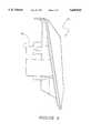
- FIG. 1is a plan elevation view of a preferred embodiment fluid delivery system made in accordance with the principles of the present invention
- FIGS. 2a-care partial cross-sectional views of the valve of the fluid delivery set and the valve actuation unit of the pump of the fluid delivery system of the present invention
- FIG. 3is a rear view of the valve receiving mechanism motor and sensor monitoring plate made in accordance with the principals of the present invention
- FIG. 4is a front view of the disc-shaped valve interface member of the preferred embodiment of the present invention detached from the valve actuation unit of the pump;
- FIG. 5is a side view of the disc-shaped valve interface member shown in FIG. 4;
- FIG. 6is a cross-sectional view of the disc-shaped valve interface member taken along line V--V of FIG. 4;
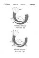
- FIGS. 7a and bare schematic views of the operating positions of the valve receiving mechanism of the pump.
- an embodiment of a fluid delivery system made in accordance with the principles of the present inventionreferred to generally by the reference numeral 10, is provided for anti-free flow attachment and detachment of a fluid delivery set with a pump which includes the capability for automatic priming, and automatic or on demand flushing of the outlet fluid flow line of the fluid delivery set.
- FIG. 1is an illustration of a fluid delivery system 10 formed in accordance with the present invention which includes a pump 12 and a disposable fluid delivery set 11 attached thereto for operation.
- the pump 12includes a pumping unit 13 and a valve actuation unit 14.
- the pumping unit 13includes a housing 15 through which protrudes a pump rotor 16.
- the rotor 16is driven by a conventional DC motor and controlled by a central processing unit (not shown) in a well known manner, such as is described in U.S. Pat. No. 4,884,013 issued to Jackson et al., which is incorporated herein by reference.
- the fluid delivery set 11preferably includes a pair of inlet fluid flow lines comprised of inlet tubes 17 and 18 which are connected to fluid containers (not shown) which contain fluids to be delivered through the fluid delivery set 11 to the patient.
- the fluidsare preferably enteral feeding fluid and flushing fluid.
- the inlet tubes 17 and 18are connected at their ends opposite the fluid reservoir containers to a stop cock valve 19 which controls the passage of fluid from the inlet tubes 17 and 18 to an outlet fluid flow line.
- the stop cock valve 19 of the fluid delivery set 11comprises a handle 22 and body 66 which are shaped to allow attachment of the valve 19 to the valve actuation unit 14 in a single unique orientation, corresponding to the closed position of the valve 19 in which fluid flow therethrough is prevented.
- the outlet fluid flow line of the fluid delivery setincludes an outlet tube 21, a drip chamber 23, a pump tube 20, and a patient connector tube 25.
- the pump tube 20surrounds the pump rotor 16 in use, and is preferably formed of an elastic material such as silicone. Rotation of the rotor 16 in the direction indicated by the arrow in FIG. 1 causes the pumping tube 20 to pump fluid into the patient connector tube 25 at a rate which is determined by the rate of rotation of the rotor 16.
- the outlet tube 21is connected to drip chamber 23 which is mounted in a recess in the housing 15 of the pumping unit 13 and secured to the inlet end of the pump tube 20.
- the outlet end of the pump tube 20is provided with a mounting member 24 which is received in another recess in the pumping unit housing 15 to thereby secure the outlet end of the pump tube 20 to the pump 12, and to maintain the pump tube 20 properly stretched over the rotor 16 for operation.
- the patient connector tube 25is connected to the outlet end of the pump tube 20 and delivers fluid from the fluid delivery system 10 to the patient, either directly, or through connection to a tube previously prepared for the patient such as a nasogastric, gastrostomy, or jejunostomy tube.
- the pumping unit 13includes an interactive control pad 26 mounted in the housing 15 thereof which allows an operator to set various functions of the system 10, such as flow rate and dose (total volume) of feeding fluid to be delivered to the patient, interrupt operations of the pump unit 13, and an increase or decrease in the designated feed dose volume or feeding fluid flow rate.
- the control pad 26allows the operator to set the flushing fluid dose and time period between each flushing cycle, or to initiate an immediate flush cycle at any time.
- the flushing fluid flow rateis preferably preset and therefore not intended to be controlled by the operator.
- the valve actuation unit 14 of the pump 12is enclosed within an actuation unit housing 28.
- the valve recess 29which is shaped to receive the step cock valve 19, the inlet tubes 17 and 18, and the outlet tube 21 in a single unique orientation (as shown in FIG. 1) is included in a valve interface 45 which is detachable from the housing 28 for cleaning when necessary.
- the interface 45forms a handle opening 30 which passes through the bottom of the valve recess 29 thereof.
- the handle opening 30passes completely through the interface 45 to allow access of the valve handle 22 to the valve receiving mechanism 32 within the housing 28.
- the handle opening 30is nearly identical in shape to the valve handle 22, so that, only proper alignment of the handle 22 with the handle opening 30 will allow the handle 22 to pass into or out of the housing 28.
- valve recess 29 and handle opening 30force a single unique orientation of the valve handle 22 with respect to the valve body 66 before the inlet tubes 17 and 18 and the outlet tube 21 can be received within the valve recess 29 and the handle 22 can pass through the handle opening 30 for purposes of attachment.
- This single unique orientation of the valve handle 22 with respect to the remainder of the valve 19corresponds to the fully closed position of the valve 19.
- the valve 19cannot be loaded into the actuation unit 13 of the pump 12 for use, nor more importantly, removed from the actuation unit 13 at any time, unless the handle 22 thereof is in its fully closed position. This of course prevents accidental fluid flow through the fluid delivery set 11 during loading thereof for use, and prevents ejection of the valve 19 from the actuation unit at any time without first closing the valve 19 against fluid flow.
- the valve handle 22when the valve handle 22 is passed through handle opening 30, it immediately contacts the chuck 33 of the valve receiving mechanism 32.
- the chuck 33is mounted to a spline 34 which is in turn mounted to the rotating shaft 35 of a stepper motor 36.
- the chuck 33is limited to translational movement over the spline 34 by the spline ridges 52, and corresponding chuck grooves 53.
- the chuck 33is biased by the spring 37 to an extended position in which the chuck face 38 thereof rests against the interior surface 46 of the interface member 45, located around the valve opening 30 thereof.
- valve 19continues movement of the valve 19 into the valve recess 29 causes the valve handle 22 to force the chuck 33 against the spring 37 and along the spline 34.
- the chuck 33will slide over the spline 34 a sufficient distance to ensure that the valve handle 22 can pass entirely through the handle opening 30 into the cylindrical recess 64.
- the outer surface of the chuck 33contacts the microswitch 40 to automatically activate the microprocessor of the pump 12.
- a control flange 39which extends rearwardly from the chuck 33, to operationally engage with photoelectric switches 41, 48 and 49.
- Thisinitiates rotation of the stepper motor 36 to rotate the chuck 33 a predetermined rotational distance. Since the valve 19 is held in a fixed unique orientation with respect to the valve interface 45 by the valve recess 29, and the valve handle 22 is fixed in the chuck face 38 by the handle positioning stubs 65, the handle 22 is forced to rotate in response to rotation of the chuck 33 by the stepper motor 36.
- the predetermined automatic initial rotation of the chuck 33therefore causes the valve handle 22 to become trapped against the interior surface 46 of the interface member 45.
- control flange 39is positioned on the chuck 33 so as to pass through the series of photo-electric switches 41, 48 and 49 as the chuck 33 is rotated by the stepper motor 36.
- the photo-electric switches 41, 48 and 49are mounted on a control plate 42 around an arcuate path followed by the control flange 39.
- the photo-electric switches 41, 48 and 49send electrical signals to the central processing unit of the pump 12, signalling the presence or absence of the control flange 39 therein in an operational manner which identifies the rotational position of the chuck 33, and thus the valve handle 22, to the central processing unit.
- the microswitch 40can also be utilized in providing feedback information to the central processing unit of the pump 12 relating to the position of the chuck 33 during pump operation. This can be accomplished by the positioning of one or more notches 43 at predetermined radial positions around the cylindrical surface of the chuck 33 to trigger the microswitch 40 each time a notch 43 is rotated therepast during operation. When a notch 43 passes the microswitch 40, it leaves sufficient space to allow the microswitch to release thereinto, and then re-trigger when the notch 43 passes. Each release or retriggering of the microswitch 40 sends a signal to the central processing unit of the pump in the manner well known to those skilled in the art of microswitch operation.
- Each notch 43can be formed to entail as much of a radial arc around the chuck 33 as desired for the proper positional operation of the chuck during use.
- the microswitch 40or a series of similar microswitches, could be used to replace one or more photoelectric switches if properly positioned to maintain the same signal logic sequence for the replaced photoelectric switches, as will be described below.
- the microswitch 40could be replaced with an equivalent switch such as a photoswitch, magneto resistive switch, etc.
- the total angle of rotation through which the valve handle 22 can be rotated in the valve body by the receiving mechanism 32is limited by the governor tab 44 on the spline 34.
- the governor tab 44interferes with the stop surfaces 54 and 55 on the motor/sensor monitoring plate 42 at each end of its predetermined maximum rotational arc to prevent accidental over rotation of the valve handle 22, and to assist in resetting the chuck in its starting position if positional errors occur during operation.
- the preferred predetermined maximum valve rotation allowed by the governor tab 44 and stop surfaces 54 and 55is approximately 120 degrees.
- the disc-shaped valve interface member 45may be detachable from the actuation unit housing 28 by means of screws or the like (which may pass through the back of the housing 28 and are not shown) to allow cleaning thereof when necessary. Removal of the interface member 45 from the housing 28 also exposes the chuck face 38 for cleaning if desired.
- the chuck 33remains held in position within the cylindrical housing extension 64 by the stop tab 61 which extends to contact the housing stop surface 62 to stop outward movement of the chuck 33 (see FIG. 2). In this manner, the sealing engagement between the chuck cup-type seal 63 and the cylindrical housing extension 64 is maintained so that fluid which may be present at the chuck face 38 cannot pass into the housing 28.
- the chuck 33includes a cup-type seal gasket 63 which forms a seal between the chuck and the cylindrical housing extension 64 and prevents the passage of fluid past the chuck 33 into the interior of the valve actuation unit 14.
- the operatorattaches a fluid delivery set 11 to the pump 12 as shown in FIG. 1. This can be accomplished by inserting the drip chamber 23 into the proper recess in the pump unit housing 15 and stretching the pump tubing 20 around the pump rotor 16.
- the mounting member 24is then inserted in its own recess in the pump unit housing 15 where its presence is sensed by a sensor (not shown) which signals the pump 12 that the outlet flow line has been properly positioned thereon.
- the fluid containers in fluid flow attachment with the inlet tubes 17 and 18are preferably suspended above the pump 12 in a well known manner.
- valve 19 of the fluid delivery setmay be manufactured and supplied to the operator in its closed position to prevent free flow through the valve 19 at all times prior to use.
- the valve 19may also include a safety tape positioned therearound to discourage rotation of the valve handle 22 from its closed position, which must be removed by the operator prior to attachment of the valve 19 to the valve actuation unit 14.
- the valve handle 22has moved completely within the housing 28.
- the stepper motorautomatically rotates an initial approximately 30 degrees from its starting position, which causes the valve handle 22 to be trapped against the interior surface 46 of the interface member 45.
- This new positionis the "initial locking position” of the valve handle 22 within the actuation unit housing 28. The initial locking position of the valve 19 does not open any fluid flow path therethrough.
- the operatormay manually actuate the on button 68 before loading the fluid delivery set 11 into the pump 12, however, no pump action will occur until the fluid delivery set is actually loaded.
- the microprocessorin turn initiates activation of the upper and lower displays 57 and 27 respectively.
- the upper display 57is preferably smaller than the lower display 27 and is used primarily to display a running total of fluid delivered, either flushing fluid or feeding fluid, so that progress towards the programmed total feeding fluid dose or total flushing fluid dose can be monitored by the operator.
- the adjacently positioned flushing light 58 and feeding light 59illuminate in turn to correspond to the particular accumulated fluid volume showing in the display 57 as will be explained in more detail below.
- the lower display 27is used for displaying more general information and to assist the operator in programming and operating the system 10.
- the lower display 27will display any preprogrammed parameters which have been entered from the key pad 26 and also scroll through messages relating to the immediate operation being performed by the pump 12. Operation of the lower display 27 will also be explained in more detail below.
- the microprocessorimmediately illuminates the flushing light 58 and causes the upper display 57 to display the accumulative volume delivered of flushing fluid (starting with zero, since no fluid has yet been delivered by the pump 12).
- the lower display 27will initially provide no information to the operator since the operator has input no programming information at this point through the key pad 26.
- the pump 12also include memory capabilities which allow it to store operational parameters which were previously input by an operator, and automatically retrieve to the preprogrammed operational parameters upon initial attachment of a fluid delivery set 11 to the pump 12.
- the automatic retrieval of preprogrammed parametersmay be time limited so that only preprogrammed information received by the pump 12 within a predetermined time period will be retrieved to and any time period greater than the time limited period will clear those values and force the operator to re-input the desired parameters.
- a preferred time period for automatic retrieval to preprogrammed parametersis approximately 16 hours.
- the pump 12initiates rotation of the stop cock handle 22 an additional approximately 30 degrees to the "flushing position", which is approximately 60 degrees from the starting position, after an additional actuation of the run/hold key 47, and makes fluid flow connection between the inlet tube 18 and the outlet tube 21.
- the pump rotor 16then draws flushing fluid from the flushing fluid container, through the inlet tube 18, and into the drip chamber 23 where the pump detects the presence of drops ensuring proper fluid flow through the fluid delivery set 11.
- valve handle 22automatically rotates an additional 60 degrees to the "feeding position" which is approximately 120 degrees from the starting position.
- the operatorthereafter must remove the defective fluid delivery set 11 and replace it with a new fluid delivery set 11 and re-initiate pump operation by inserting the fluid delivery set stop cock valve 19 into the pump's valve receiving mechanism 32.
- the pump 12rotates once more to the feeding position and continues to pump enteral fluid through the fluid delivery set 11 until the entire outlet fluid flow line of the set is filled with feeding fluid. It is preferred that the priming operation to fill the outlet fluid flow line with feeding fluid be performed at the flushing flow rate in order to speed up the priming process. While priming, the lower display 27 indicates that the priming operation is in progress by displaying the phrase "filling set" for all phases of priming.
- the priming operationautomatically stops by stopping the rotor 16 and the pump 12 rotating the valve handle 22 in the reverse direction a distance of 30 degrees to the temporary off position.
- the operatorthen connects the patient connector tube 25 to the patient for feeding, and enters the desired total feed dose and desired feeding flow rate on the key pad 26.
- the operatoralso enters a desired flash dose, and the desired time interval between each flushing cycle initiation.
- the automatic flush enabled light 60illuminates, and remains illuminated until the entire feeding cycle is completed or until the automatic flushing feature is disabled by the operator.
- the flushing flow rateis preferably fixed by the pump 12 at 1000 ml/hr and is therefore not entered by the operator.
- the feeding flow rateis automatically displayed in the lower display 27, and the cumulative delivered feeding fluid volume is shown in the upper display 57.
- the feeding light 59is illuminated to signal the operator that feeding fluid is being delivered to the patient.
- the pump 12Periodically, at each predetermined flush interval (minus the time required to pump the volume of the outlet fluid line at the feeding fluid flow rate), the pump 12 causes the valve handle 22 to be rotated to the flushing position to stop enteral feeding fluid flow from inlet tube 17, and open a flushing fluid flow path from inlet tube 18. Simultaneously, the flushing light 58 begins flashing (while the feeding light 59 remains on), indicating that a flushing cycle has commenced but feeding fluid is still being delivered to the patient at the feeding fluid flow rate. The pump continues to pump at the programmed feeding fluid flow rate until the entire outlet fluid flow line of the delivery set 11 is filled with flushing fluid (i.e., until all of the feeding fluid in the outlet fluid flow line has been fed to the patient).
- the pumpautomatically begins pumping flushing fluid at the predetermined flushing fluid flow rate.
- the lower display 27displays a scrolling dashed line at this time.
- the flushing light 58is continuously illuminated and the feeding light 59 goes off.
- the upper display 57then begins showing the cumulative flushing fluid volume as it is being delivered.
- the valve 22again rotates to the feeding position to stop flow of flushing fluid from inlet tube 18 and open flow of feeding fluid from inlet tube 17.
- Feeding fluidis then delivered at the predetermined flushing fluid flow rate until the entire outlet fluid flow line is filled with feeding fluid (i.e., until all of the flushing fluid has been delivered to the patient).
- the feeding light 59flashes, and the flushing light 58 remains on, indicating that feeding is about to recommence but flushing fluid is still being delivered to the patient at the flushing fluid flow rate.
- the pump 12then automatically begins delivering feeding fluid at the programmed feeding fluid flow rate which is displayed in the lower display 27, and the feeding light 59 is continuously illuminated and the flushing light 58 goes off.
- the upper display 57then again shows the cumulative feeding volume as it is being delivered to the patient.
- the operatorneed only push the run/hold button 47 and the "flush now" button 50 located on the key pad 26.
- the lower display 27requests the operator to input a flush dose by displaying the phrase "flsh dose”. The operator enters the desired flush dose and again pushes the flush now button 50 and the newly programmed flushing cycle commences immediately.
- the operatorpresses the run/hold button 47.
- the pump 12initiates rotation of the handle 22 to the temporary off position and halts rotation of the rotor 16. It should be noted that the handle 22 is not rotated to the starting position when the run/hold button 47 is pressed, since this will release the handle 22 from its entrapment behind the valve interface member 45 resulting in ejection of the valve handle 22 from the handle opening 30 by the force of the spring 37 of the valve receiving mechanism 32.
- the pumpWhenever an operational error such as a flush or feed flow alarm occurs, the pump will automatically move the valve handle 22 to its temporary off position and stop the rotor 16. Once the problem is resolved, the operator presses the run/hold button 47 and operation of the fluid delivery system 10 will resume.
- the pump 12automatically moves the valve handle 22 to the temporary off position and signals the operator of the completion of fluid delivery. At any time, the operator can push the off key 51 and the valve receiving mechanism 32 will rotate the valve handle 22 to the starting position and the spring 37 will eject the valve 19 from the valve recess 29.
- FIGS. 7a and ba schematic of the photoelectric switches 41, 48 and 49 is shown with each position of the control flange 39 of the chuck 33 in operation described as positions A-F, with FIG. 7a showing the forward rotation (clockwise as shown) and FIG. 7b showing the return rotation (counterclockwise as shown) of the chuck 33.
- Position (A)describes the position of the control flange 39 when no valve is loaded into the valve receiving mechanism 32. In this position, the control flange 39 is located above all of the photoelectric switches and not operationally engaged.
- Position (B)corresponds to the starting position of the valve receiving mechanism 32 in which the control flange 39 interrupts the photoelectric switches 48 and 49 and leaves switch 41 open.
- Position (C)corresponds to the initial locking position of the pump 12 in which the control flange 39 interrupts all three photoelectric switches 41, 48 and 49.
- position (D)corresponding to the flushing position
- the control flange 39interrupts photoelectric switches 49 and 41, leaving switch 48 open.
- position (E)corresponding to the temporary off position
- the flange 39interrupts only microswitch 41.
- position (F)corresponding to the feeding position, the flange 39 interrupts photoelectric switches 41 and 48, leaving switch 49 open.
- Positions (G), (H), (I)correspond to positions (E), (D), and (C) respectively except they are entered from the return direction.
- (G)corresponds to the intermediate hold position
- (H)corresponds to the flush position
- (I)corresponds to the lock position.
- each position of the control flange 39causes the photoelectric switches 41, 48 and 49 to send a unique signal to the microprocessor of the pump 12 which it can equate to the rotational position of the valve handle 22 in carrying out the desired fluid delivery by the system 10.
- the exact position of the control flange 39determines the transition direction of the signal sent to the microprocessor by the photoelectric switches 41, 48 and 49.
- the valve actuation unit 14includes a fail safe default which monitors whether each rotation of the chuck 33 generates the expected signals by the photoelectric switches 41, 48 and 49. If not, the microprocessor causes the valve receiving mechanism 30 to reset to the starting position and causes the pump 12 to stop. In this manner, the valve actuation unit 14 cannot be "tricked” into initial activation by depression of the chuck 33 down to its actuation of the microswitch 40 by some device other than a valve handle 22 which holds the chuck 33 in its compressed position and the control flange 39 thereof in operational position relative to the photoelectric switches 41, 48 and 49.
- valve actuation unitShould operation of the valve actuation unit be initiated by actuation of the microswitch 40, yet the chuck 33 remain in its extended position such that the control flange 39 fails to interact with the photoelectric switches 41, 48 and 49 (indicating that no valve handle 22 is positioned in the valve receiving mechanism 32) the valve receiving mechanism 32 resets to its starting position, the pump 12 stops, and the valve 19 is ejected from the valve receiving mechanism 32.
- the fluid delivery system 10 of the present inventioncan operate with a fluid delivery set which does not include an auxiliary flushing fluid container, and therefore also does not contain the inlet tube 18.
- the previously described priming cyclewill detect the absence of any fluid drops entering the drip chamber 23 when the valve is rotated to the flushing position for priming, and the microprocessor will then only allow the pump 12 to be programmed for delivery of the primary feeding fluid by disabling the automatic and manual flushing features of the system 10.
Landscapes
- Health & Medical Sciences (AREA)
- Vascular Medicine (AREA)
- Engineering & Computer Science (AREA)
- Anesthesiology (AREA)
- Biomedical Technology (AREA)
- Heart & Thoracic Surgery (AREA)
- Hematology (AREA)
- Life Sciences & Earth Sciences (AREA)
- Animal Behavior & Ethology (AREA)
- General Health & Medical Sciences (AREA)
- Public Health (AREA)
- Veterinary Medicine (AREA)
- Emergency Medicine (AREA)
- Infusion, Injection, And Reservoir Apparatuses (AREA)
Abstract
Description
Claims (8)
Priority Applications (1)
| Application Number | Priority Date | Filing Date | Title |
|---|---|---|---|
| US08/481,592US5649810A (en) | 1994-11-28 | 1995-06-07 | Apparatus for delivering fluid to a patient |
Applications Claiming Priority (2)
| Application Number | Priority Date | Filing Date | Title |
|---|---|---|---|
| US08/345,086US5584671A (en) | 1994-11-28 | 1994-11-28 | Apparatus for delivering fluid to a patient |
| US08/481,592US5649810A (en) | 1994-11-28 | 1995-06-07 | Apparatus for delivering fluid to a patient |
Related Parent Applications (1)
| Application Number | Title | Priority Date | Filing Date |
|---|---|---|---|
| US08/345,086ContinuationUS5584671A (en) | 1994-11-28 | 1994-11-28 | Apparatus for delivering fluid to a patient |
Publications (1)
| Publication Number | Publication Date |
|---|---|
| US5649810Atrue US5649810A (en) | 1997-07-22 |
Family
ID=23353450
Family Applications (2)
| Application Number | Title | Priority Date | Filing Date |
|---|---|---|---|
| US08/345,086Expired - LifetimeUS5584671A (en) | 1994-11-28 | 1994-11-28 | Apparatus for delivering fluid to a patient |
| US08/481,592Expired - LifetimeUS5649810A (en) | 1994-11-28 | 1995-06-07 | Apparatus for delivering fluid to a patient |
Family Applications Before (1)
| Application Number | Title | Priority Date | Filing Date |
|---|---|---|---|
| US08/345,086Expired - LifetimeUS5584671A (en) | 1994-11-28 | 1994-11-28 | Apparatus for delivering fluid to a patient |
Country Status (3)
| Country | Link |
|---|---|
| US (2) | US5584671A (en) |
| AU (1) | AU4164896A (en) |
| WO (1) | WO1996017174A1 (en) |
Cited By (31)
| Publication number | Priority date | Publication date | Assignee | Title |
|---|---|---|---|---|
| US6165154A (en)* | 1995-06-07 | 2000-12-26 | Deka Products Limited Partnership | Cassette for intravenous-line flow-control system |
| US6364857B1 (en) | 1995-06-07 | 2002-04-02 | Deka Products Limited Partnership | Cassette for intravenous-line flow-control system |
| US6464667B1 (en) | 1997-08-22 | 2002-10-15 | Deka Products Limited Partnership | Method and cassette for delivering intravenous drugs |
| US6709417B1 (en) | 1995-06-07 | 2004-03-23 | Deka Products Limited Partnership | Valve for intravenous-line flow-control system |
| WO2005005929A3 (en)* | 2003-07-09 | 2005-03-24 | Tecpharma Licensing Ag | Contactless scanning by means of a magnetoresistive sensor |
| US20050095153A1 (en)* | 2003-10-30 | 2005-05-05 | Deka Products Limited Partnership | Pump cassette bank |
| US20050095576A1 (en)* | 2003-10-30 | 2005-05-05 | Deka Products Limited Partnership | System, device, and method for mixing a substance with a liquid |
| US20050096583A1 (en)* | 2003-10-30 | 2005-05-05 | Deka Products Limited Partnership | Pump cassette with spiking assembly |
| US20060153693A1 (en)* | 2004-12-31 | 2006-07-13 | Patrick Fiechter | Administering apparatus comprising a service life timer |
| US20070078431A1 (en)* | 2005-09-30 | 2007-04-05 | Sherwood Services Ag | Administration feeding set and flow control apparatus with secure loading features |
| US20070077152A1 (en)* | 2005-09-30 | 2007-04-05 | Sherwood Services Ag | Aliquot correction for feeding set degradation |
| US20070253833A1 (en)* | 2006-03-02 | 2007-11-01 | Tyco Healthcare Group Lp | Pump Set with Safety Interlock |
| US20080119822A1 (en)* | 2006-11-17 | 2008-05-22 | Tyco Healthcare Group Lp | Enteral fluid delivery system and method for opeating the same |
| US20080135725A1 (en)* | 2006-12-11 | 2008-06-12 | Tyco Healthcare Group Lp | Pump set and pump with electromagnetic radiation operated interlock |
| US20080147008A1 (en)* | 2006-12-15 | 2008-06-19 | Tyco Healthcare Group Lp | Optical detection of medical pump rotor position |
| US20080167617A1 (en)* | 2007-01-05 | 2008-07-10 | Tyco Heathcare Group Lp | Pump set for administering fluid with secure loading features and manufacture of component therefor |
| USD615644S1 (en) | 2008-08-15 | 2010-05-11 | Ost Medical, Inc. | Anti-free flow modulator |
| US7722573B2 (en) | 2006-03-02 | 2010-05-25 | Covidien Ag | Pumping apparatus with secure loading features |
| US7758551B2 (en) | 2006-03-02 | 2010-07-20 | Covidien Ag | Pump set with secure loading features |
| US7763005B2 (en) | 2006-03-02 | 2010-07-27 | Covidien Ag | Method for using a pump set having secure loading features |
| US20100211022A1 (en)* | 2009-02-19 | 2010-08-19 | Tyco Healthcare Group Lp | Manual valve actuator for medical fluid delivery set |
| US7927304B2 (en) | 2006-03-02 | 2011-04-19 | Tyco Healthcare Group Lp | Enteral feeding pump and feeding set therefor |
| US7937775B2 (en) | 2005-08-09 | 2011-05-10 | Microtek Medical, Inc. | Surgical protective head gear assembly including high volume air delivery system |
| EP2384780A3 (en)* | 2004-05-25 | 2012-03-07 | Covidien AG | Flow control apparatus |
| WO2012044388A1 (en)* | 2010-10-01 | 2012-04-05 | Smiths Medical Asd, Inc. | Flushing a fluid line from a medical pump |
| JP2013538644A (en)* | 2010-10-01 | 2013-10-17 | スミス・メディカル・エイエスディ・インコーポレーテッド | Cleaning fluid lines from medical pumps |
| USD694396S1 (en)* | 2010-12-22 | 2013-11-26 | Fenwal, Inc. | Blood collection device |
| US9067009B2 (en) | 2013-01-25 | 2015-06-30 | Acist Medical Systems, Inc. | Regulating flow paths in a medical injection system |
| US10294450B2 (en) | 2015-10-09 | 2019-05-21 | Deka Products Limited Partnership | Fluid pumping and bioreactor system |
| EP2140906B1 (en)* | 2004-05-25 | 2019-09-25 | Cardinal Health Ireland Unlimited Company | Valve mechanism to be used with an administration feeding set |
| US11299705B2 (en) | 2016-11-07 | 2022-04-12 | Deka Products Limited Partnership | System and method for creating tissue |
Families Citing this family (30)
| Publication number | Priority date | Publication date | Assignee | Title |
|---|---|---|---|---|
| US5807333A (en)* | 1995-09-21 | 1998-09-15 | Abbott Laboratories | Peristaltic pump and fluid delivery set |
| US5745378A (en)* | 1995-12-04 | 1998-04-28 | Abbott Laboratories | Parameter input for drug delivery pump |
| US5853387A (en)* | 1996-04-03 | 1998-12-29 | Abbott Laboratories | Pump with programmable hold |
| IL120654A (en)* | 1997-04-11 | 2001-08-08 | Nestle Sa | Administration of two liquids to a patient |
| US20080073610A1 (en)* | 1997-08-22 | 2008-03-27 | Manning Casey P | Stopcock valve |
| US7094216B2 (en)* | 2000-10-18 | 2006-08-22 | Medrad, Inc. | Injection system having a pressure isolation mechanism and/or a handheld controller |
| US20080154214A1 (en)* | 2006-12-22 | 2008-06-26 | Medrad, Inc. | Flow Based Pressure Isolation and Fluid Delivery System Including Flow Based Pressure Isolation |
| US20030130645A1 (en)* | 2001-12-03 | 2003-07-10 | Tandem Medical, Inc. | Devices and methods for delivery of medically appropriate fluids |
| US7565301B2 (en)* | 2002-07-26 | 2009-07-21 | Curlin Medical Inc. | System and method for remotely operating a peristaltic pump |
| US6902544B2 (en)* | 2003-01-22 | 2005-06-07 | Codman & Shurtleff, Inc. | Troubleshooting accelerator system for implantable drug delivery pumps |
| US7556619B2 (en) | 2004-04-16 | 2009-07-07 | Medrad, Inc. | Fluid delivery system having a fluid level sensor and a fluid control device for isolating a patient from a pump device |
| US7794423B2 (en) | 2004-05-25 | 2010-09-14 | Covidien Ag | Re-certification system for a flow control apparatus |
| US9011377B2 (en) | 2008-11-05 | 2015-04-21 | Bayer Medical Care Inc. | Fluid mixing control device for a multi-fluid delivery system |
| US9433730B2 (en) | 2013-03-14 | 2016-09-06 | Bayer Healthcare Llc | Fluid mixing control device for a multi-fluid delivery system |
| US7766883B2 (en) | 2007-10-30 | 2010-08-03 | Medrad, Inc. | System and method for proportional mixing and continuous delivery of fluids |
| US8057437B2 (en)* | 2007-08-31 | 2011-11-15 | Hospira, Inc. | Radially sealing vavle for an infusion set |
| DE102007052805B4 (en)* | 2007-11-06 | 2012-09-06 | Erbe Elektromedizin Gmbh | Water jet surgical device and method for operating such |
| US8154274B2 (en) | 2010-05-11 | 2012-04-10 | Tyco Healthcare Group Lp | Safety interlock |
| US20150133861A1 (en) | 2013-11-11 | 2015-05-14 | Kevin P. McLennan | Thermal management system and method for medical devices |
| US10143795B2 (en) | 2014-08-18 | 2018-12-04 | Icu Medical, Inc. | Intravenous pole integrated power, control, and communication system and method for an infusion pump |
| CA2964105C (en)* | 2014-10-15 | 2023-10-17 | Covidien Lp | Occlusion detection for flow control apparatus |
| NZ737340A (en) | 2015-05-26 | 2019-06-28 | Icu Medical Inc | Disposable infusion fluid delivery device for programmable large volume drug delivery |
| CN105597186B (en)* | 2016-02-17 | 2023-03-28 | 美昕医疗器械(昆山)有限公司 | Free flow prevention device for feeding pump |
| EP3631810A1 (en) | 2017-05-26 | 2020-04-08 | Bayer Healthcare LLC | Injector state logic with hemodynamic monitoring |
| WO2020006326A1 (en)* | 2018-06-29 | 2020-01-02 | Generica Medical International, Inc. | Enteral feeding systems and methods |
| USD939079S1 (en) | 2019-08-22 | 2021-12-21 | Icu Medical, Inc. | Infusion pump |
| US11963934B2 (en)* | 2021-05-27 | 2024-04-23 | Zevex, Inc. | Flow valve for use with enteral feeding pump flush module |
| USD1052728S1 (en) | 2021-11-12 | 2024-11-26 | Icu Medical, Inc. | Medical fluid infusion pump |
| WO2023230015A1 (en)* | 2022-05-23 | 2023-11-30 | Megahed Ahmed | Methods, systems, apparatuses, and devices for facilitating maintaining patency of a medical catheter |
| US20250135096A1 (en)* | 2023-10-27 | 2025-05-01 | Medcaptain Medical Technology Co., Ltd. | Fluid delivery mechanism and nutrient pump |
Citations (24)
| Publication number | Priority date | Publication date | Assignee | Title |
|---|---|---|---|---|
| US3091239A (en)* | 1958-08-25 | 1963-05-28 | Moeller Wilhelm | Apparatus for intravasal injection of gaseous and liquid media |
| US3097585A (en)* | 1959-07-17 | 1963-07-16 | Speed O Print Business Machine | Photocopying devices |
| US3831625A (en)* | 1973-02-20 | 1974-08-27 | D Roediger | Intravenous safety device |
| US3858601A (en)* | 1973-02-01 | 1975-01-07 | Roto Swivel Corp Inc | Movable appliance assembly and gas cut-off valve |
| US3957082A (en)* | 1974-09-26 | 1976-05-18 | Arbrook, Inc. | Six-way stopcock |
| US3985133A (en)* | 1974-05-28 | 1976-10-12 | Imed Corporation | IV pump |
| US4219021A (en)* | 1978-02-27 | 1980-08-26 | Fink Joseph L | Multi-position stop-cock valve for intravenous administration of multiple medications |
| US4460358A (en)* | 1980-11-07 | 1984-07-17 | Ivac Corporation | Combined load and latch mechanism for fluid flow control apparatus |
| US4557725A (en)* | 1984-05-04 | 1985-12-10 | Oximetrix, Inc. | I. V. Pump cassette |
| US4585411A (en)* | 1983-07-06 | 1986-04-29 | Italimpianti Societa Italiana Impianti P.A. | Method and walking beam furnace for the intermediate heating of pipes in hot rolling mills |
| US4585442A (en)* | 1984-07-26 | 1986-04-29 | Ivy Medical, Inc. | Miniature intravenous infusion rate controller |
| US4604093A (en)* | 1984-06-12 | 1986-08-05 | I-Flow Corporation | Apparatus and method for administering multiple fluid infusions |
| US4689043A (en)* | 1986-03-19 | 1987-08-25 | Imed Corporation | IV tube activator |
| US4884013A (en)* | 1988-01-15 | 1989-11-28 | Sherwood Medical Company | Motor unit for a fluid pump and method of operation |
| US4954046A (en)* | 1989-12-08 | 1990-09-04 | Imed Corporation | Peristaltic pump with mechanism for maintaining linear flow |
| US5005604A (en)* | 1984-07-13 | 1991-04-09 | Aslanian Jerry L | Flow control device for administration of intravenous fluids |
| US5017192A (en)* | 1989-10-20 | 1991-05-21 | Minnesota Mining And Manufacturing Company | Free flow prevention system for infusion pump |
| US5057081A (en)* | 1990-06-15 | 1991-10-15 | Sherwood Medical Company | Peristaltic infusion device |
| US5156186A (en)* | 1989-10-31 | 1992-10-20 | Manska Wayne E | Stopcock valve |
| US5219327A (en)* | 1990-10-31 | 1993-06-15 | Terumo Kabushiki Kaisha | Transfusion pump |
| US5242407A (en)* | 1992-07-23 | 1993-09-07 | Minnesota Mining And Manufacturing Company | Infusion pump with improved contamination resistance |
| US5244463A (en)* | 1991-12-06 | 1993-09-14 | Block Medical, Inc. | Programmable infusion pump |
| US5364364A (en)* | 1993-08-04 | 1994-11-15 | Ivac Corporation | Automatic flow control valve system |
| US5374251A (en)* | 1993-04-14 | 1994-12-20 | Entracare | Medical fluid pump apparatus |
- 1994
- 1994-11-28USUS08/345,086patent/US5584671A/ennot_activeExpired - Lifetime
- 1995
- 1995-06-07USUS08/481,592patent/US5649810A/ennot_activeExpired - Lifetime
- 1995-11-27WOPCT/US1995/015003patent/WO1996017174A1/enactiveApplication Filing
- 1995-11-27AUAU41648/96Apatent/AU4164896A/ennot_activeAbandoned
Patent Citations (25)
| Publication number | Priority date | Publication date | Assignee | Title |
|---|---|---|---|---|
| US3091239A (en)* | 1958-08-25 | 1963-05-28 | Moeller Wilhelm | Apparatus for intravasal injection of gaseous and liquid media |
| US3097585A (en)* | 1959-07-17 | 1963-07-16 | Speed O Print Business Machine | Photocopying devices |
| US3858601A (en)* | 1973-02-01 | 1975-01-07 | Roto Swivel Corp Inc | Movable appliance assembly and gas cut-off valve |
| US3831625A (en)* | 1973-02-20 | 1974-08-27 | D Roediger | Intravenous safety device |
| US3985133A (en)* | 1974-05-28 | 1976-10-12 | Imed Corporation | IV pump |
| US3957082A (en)* | 1974-09-26 | 1976-05-18 | Arbrook, Inc. | Six-way stopcock |
| US4219021A (en)* | 1978-02-27 | 1980-08-26 | Fink Joseph L | Multi-position stop-cock valve for intravenous administration of multiple medications |
| US4460358A (en)* | 1980-11-07 | 1984-07-17 | Ivac Corporation | Combined load and latch mechanism for fluid flow control apparatus |
| US4585411A (en)* | 1983-07-06 | 1986-04-29 | Italimpianti Societa Italiana Impianti P.A. | Method and walking beam furnace for the intermediate heating of pipes in hot rolling mills |
| US4585411B1 (en)* | 1983-07-06 | 1991-03-12 | Italimpianti Societe Italiana | |
| US4557725A (en)* | 1984-05-04 | 1985-12-10 | Oximetrix, Inc. | I. V. Pump cassette |
| US4604093A (en)* | 1984-06-12 | 1986-08-05 | I-Flow Corporation | Apparatus and method for administering multiple fluid infusions |
| US5005604A (en)* | 1984-07-13 | 1991-04-09 | Aslanian Jerry L | Flow control device for administration of intravenous fluids |
| US4585442A (en)* | 1984-07-26 | 1986-04-29 | Ivy Medical, Inc. | Miniature intravenous infusion rate controller |
| US4689043A (en)* | 1986-03-19 | 1987-08-25 | Imed Corporation | IV tube activator |
| US4884013A (en)* | 1988-01-15 | 1989-11-28 | Sherwood Medical Company | Motor unit for a fluid pump and method of operation |
| US5017192A (en)* | 1989-10-20 | 1991-05-21 | Minnesota Mining And Manufacturing Company | Free flow prevention system for infusion pump |
| US5156186A (en)* | 1989-10-31 | 1992-10-20 | Manska Wayne E | Stopcock valve |
| US4954046A (en)* | 1989-12-08 | 1990-09-04 | Imed Corporation | Peristaltic pump with mechanism for maintaining linear flow |
| US5057081A (en)* | 1990-06-15 | 1991-10-15 | Sherwood Medical Company | Peristaltic infusion device |
| US5219327A (en)* | 1990-10-31 | 1993-06-15 | Terumo Kabushiki Kaisha | Transfusion pump |
| US5244463A (en)* | 1991-12-06 | 1993-09-14 | Block Medical, Inc. | Programmable infusion pump |
| US5242407A (en)* | 1992-07-23 | 1993-09-07 | Minnesota Mining And Manufacturing Company | Infusion pump with improved contamination resistance |
| US5374251A (en)* | 1993-04-14 | 1994-12-20 | Entracare | Medical fluid pump apparatus |
| US5364364A (en)* | 1993-08-04 | 1994-11-15 | Ivac Corporation | Automatic flow control valve system |
Non-Patent Citations (10)
| Title |
|---|
| "Ross Clinical Study BD28 Enteral Nutrition Pump Performance and Efficacy Study" Operating Manual, Jun. 1991, pp. 1-12. |
| EntraCare Corp., "UltraFlo™" information page, date unknown, one page. |
| EntraCare Corp., UltraFlo information page, date unknown, one page.* |
| Ross Clinical Study BD28 Enteral Nutrition Pump Performance and Efficacy Study Operating Manual, Jun. 1991, pp. 1 12.* |
| Ross Laboratories, "Flexiflo® Quantum™ Enteral Pump" Instructions for Use, Mar. 1992, two pages. |
| Ross Laboratories, "Flexiflo® Quantum™ Enteral Pump" Operating Manual, 1992, pp. 1-19. |
| Ross Laboratories, Flexiflo Quantum Enteral Pump Instructions for Use, Mar. 1992, two pages.* |
| Ross Laboratories, Flexiflo Quantum Enteral Pump Operating Manual, 1992, pp. 1 19.* |
| Sherwood Medical Company, "Ross Quantum Pump" Bulletin, Nov. 11, 1992, pp. 1-4. |
| Sherwood Medical Company, Ross Quantum Pump Bulletin, Nov. 11, 1992, pp. 1 4.* |
Cited By (70)
| Publication number | Priority date | Publication date | Assignee | Title |
|---|---|---|---|---|
| US6364857B1 (en) | 1995-06-07 | 2002-04-02 | Deka Products Limited Partnership | Cassette for intravenous-line flow-control system |
| US6709417B1 (en) | 1995-06-07 | 2004-03-23 | Deka Products Limited Partnership | Valve for intravenous-line flow-control system |
| US6165154A (en)* | 1995-06-07 | 2000-12-26 | Deka Products Limited Partnership | Cassette for intravenous-line flow-control system |
| US7214210B2 (en) | 1997-08-22 | 2007-05-08 | Deka Products Limited Partnership | Cassette and method for drug preparation and delivery |
| US6464667B1 (en) | 1997-08-22 | 2002-10-15 | Deka Products Limited Partnership | Method and cassette for delivering intravenous drugs |
| US20040176724A1 (en)* | 1997-08-22 | 2004-09-09 | Kamen Dean L, | Cassette and method for drug preparation and delivery |
| US9408966B2 (en) | 1997-08-22 | 2016-08-09 | Deka Products Limited Partnership | System and method for drug preparation and delivery |
| US7511480B2 (en) | 2003-07-09 | 2009-03-31 | Tecpharma Licensing Ag | Non-contact scanning using magneto-resistive sensor |
| US20060161112A1 (en)* | 2003-07-09 | 2006-07-20 | Beat Steffen | Non-contact scanning using a magneto-resistive sensor |
| WO2005005929A3 (en)* | 2003-07-09 | 2005-03-24 | Tecpharma Licensing Ag | Contactless scanning by means of a magnetoresistive sensor |
| US7632078B2 (en) | 2003-10-30 | 2009-12-15 | Deka Products Limited Partnership | Pump cassette bank |
| US7461968B2 (en) | 2003-10-30 | 2008-12-09 | Deka Products Limited Partnership | System, device, and method for mixing liquids |
| US7632080B2 (en) | 2003-10-30 | 2009-12-15 | Deka Products Limited Partnership | Bezel assembly for pneumatic control |
| US20050096583A1 (en)* | 2003-10-30 | 2005-05-05 | Deka Products Limited Partnership | Pump cassette with spiking assembly |
| US20050095576A1 (en)* | 2003-10-30 | 2005-05-05 | Deka Products Limited Partnership | System, device, and method for mixing a substance with a liquid |
| US7662139B2 (en) | 2003-10-30 | 2010-02-16 | Deka Products Limited Partnership | Pump cassette with spiking assembly |
| US20050095152A1 (en)* | 2003-10-30 | 2005-05-05 | Deka Products Limited Partnership | Door locking mechanism |
| US20050095141A1 (en)* | 2003-10-30 | 2005-05-05 | Deka Products Limited Partnership | System and method for pumping fluid using a pump cassette |
| US7354190B2 (en) | 2003-10-30 | 2008-04-08 | Deka Products Limited Partnership | Two-stage mixing system, apparatus, and method |
| US20050095153A1 (en)* | 2003-10-30 | 2005-05-05 | Deka Products Limited Partnership | Pump cassette bank |
| US20050095154A1 (en)* | 2003-10-30 | 2005-05-05 | Deka Products Limited Partnership | Bezel assembly for pneumatic control |
| US8158102B2 (en) | 2003-10-30 | 2012-04-17 | Deka Products Limited Partnership | System, device, and method for mixing a substance with a liquid |
| EP2140906B1 (en)* | 2004-05-25 | 2019-09-25 | Cardinal Health Ireland Unlimited Company | Valve mechanism to be used with an administration feeding set |
| EP2384780A3 (en)* | 2004-05-25 | 2012-03-07 | Covidien AG | Flow control apparatus |
| US20060153693A1 (en)* | 2004-12-31 | 2006-07-13 | Patrick Fiechter | Administering apparatus comprising a service life timer |
| US7937775B2 (en) | 2005-08-09 | 2011-05-10 | Microtek Medical, Inc. | Surgical protective head gear assembly including high volume air delivery system |
| US20070078431A1 (en)* | 2005-09-30 | 2007-04-05 | Sherwood Services Ag | Administration feeding set and flow control apparatus with secure loading features |
| US20090191066A1 (en)* | 2005-09-30 | 2009-07-30 | Covidien Ag | Aliquot correction for feeding set degradation |
| US7534099B2 (en) | 2005-09-30 | 2009-05-19 | Covidien Ag | Aliquot correction for feeding set degradation |
| US8360757B2 (en) | 2005-09-30 | 2013-01-29 | Covidien Ag | Aliquot correction for feeding set degradation |
| US20070077152A1 (en)* | 2005-09-30 | 2007-04-05 | Sherwood Services Ag | Aliquot correction for feeding set degradation |
| AU2006222694B2 (en)* | 2005-09-30 | 2010-04-22 | Cardinal Health 529, Llc | Aliquot correction for feeding set degradation |
| CN101011615B (en)* | 2005-09-30 | 2011-01-19 | 舍伍德服务股份公司 | Administration feeding set and flow control apparatus with reliable loading characteristics |
| US7846131B2 (en)* | 2005-09-30 | 2010-12-07 | Covidien Ag | Administration feeding set and flow control apparatus with secure loading features |
| US7722573B2 (en) | 2006-03-02 | 2010-05-25 | Covidien Ag | Pumping apparatus with secure loading features |
| US20070253833A1 (en)* | 2006-03-02 | 2007-11-01 | Tyco Healthcare Group Lp | Pump Set with Safety Interlock |
| US7763005B2 (en) | 2006-03-02 | 2010-07-27 | Covidien Ag | Method for using a pump set having secure loading features |
| US9402789B2 (en) | 2006-03-02 | 2016-08-02 | Covidien Ag | Pump set having secure loading features |
| US7758551B2 (en) | 2006-03-02 | 2010-07-20 | Covidien Ag | Pump set with secure loading features |
| US7722562B2 (en) | 2006-03-02 | 2010-05-25 | Tyco Healthcare Group Lp | Pump set with safety interlock |
| US7927304B2 (en) | 2006-03-02 | 2011-04-19 | Tyco Healthcare Group Lp | Enteral feeding pump and feeding set therefor |
| US20080119822A1 (en)* | 2006-11-17 | 2008-05-22 | Tyco Healthcare Group Lp | Enteral fluid delivery system and method for opeating the same |
| US20080135725A1 (en)* | 2006-12-11 | 2008-06-12 | Tyco Healthcare Group Lp | Pump set and pump with electromagnetic radiation operated interlock |
| US7560686B2 (en) | 2006-12-11 | 2009-07-14 | Tyco Healthcare Group Lp | Pump set and pump with electromagnetic radiation operated interlock |
| US20080147008A1 (en)* | 2006-12-15 | 2008-06-19 | Tyco Healthcare Group Lp | Optical detection of medical pump rotor position |
| US20080167617A1 (en)* | 2007-01-05 | 2008-07-10 | Tyco Heathcare Group Lp | Pump set for administering fluid with secure loading features and manufacture of component therefor |
| US8021336B2 (en) | 2007-01-05 | 2011-09-20 | Tyco Healthcare Group Lp | Pump set for administering fluid with secure loading features and manufacture of component therefor |
| USD615644S1 (en) | 2008-08-15 | 2010-05-11 | Ost Medical, Inc. | Anti-free flow modulator |
| US9114243B2 (en) | 2009-02-19 | 2015-08-25 | Covidien Lp | Manual valve actuator for medical fluid delivery set |
| CN101822869A (en)* | 2009-02-19 | 2010-09-08 | 泰科保健集团有限合伙公司 | The hand control valve actuating device that is used for the medical fluid delivery device |
| EP2221084A1 (en)* | 2009-02-19 | 2010-08-25 | Tyco Healthcare Group LP | Manual valve actuator for medical fluid delivery set |
| US20100211022A1 (en)* | 2009-02-19 | 2010-08-19 | Tyco Healthcare Group Lp | Manual valve actuator for medical fluid delivery set |
| CN101822869B (en)* | 2009-02-19 | 2014-02-19 | 泰科保健集团有限合伙公司 | Manual valve actuator for medical fluid delivery set |
| CN108187182A (en)* | 2010-10-01 | 2018-06-22 | 史密斯医疗Asd公司 | Use the method and medical pump of medical pump rinse fluid art pipe |
| WO2012044388A1 (en)* | 2010-10-01 | 2012-04-05 | Smiths Medical Asd, Inc. | Flushing a fluid line from a medical pump |
| US12064596B2 (en) | 2010-10-01 | 2024-08-20 | Smiths Medical Asd, Inc. | Flushing a fluid line from a medical pump |
| AU2011307499B2 (en)* | 2010-10-01 | 2014-06-12 | Icu Medical, Inc. | Flushing a fluid line from a medical pump |
| US11224692B2 (en) | 2010-10-01 | 2022-01-18 | Smiths Medical Asd, Inc. | Flushing a fluid line from a medical pump |
| JP2013538644A (en)* | 2010-10-01 | 2013-10-17 | スミス・メディカル・エイエスディ・インコーポレーテッド | Cleaning fluid lines from medical pumps |
| CN103189082A (en)* | 2010-10-01 | 2013-07-03 | 史密斯医疗Asd公司 | Flush the fluid line with a medical pump |
| US10143800B2 (en) | 2010-10-01 | 2018-12-04 | Smiths Medical Asd, Inc. | Flushing a fluid line from a medical pump |
| US8876793B2 (en) | 2010-10-01 | 2014-11-04 | Smiths Medical Asd, Inc. | Flushing a fluid line from a medical pump |
| USD694396S1 (en)* | 2010-12-22 | 2013-11-26 | Fenwal, Inc. | Blood collection device |
| US9067009B2 (en) | 2013-01-25 | 2015-06-30 | Acist Medical Systems, Inc. | Regulating flow paths in a medical injection system |
| US10294450B2 (en) | 2015-10-09 | 2019-05-21 | Deka Products Limited Partnership | Fluid pumping and bioreactor system |
| US10808218B2 (en) | 2015-10-09 | 2020-10-20 | Deka Products Limited Partnership | Fluid pumping and bioreactor system |
| US11299705B2 (en) | 2016-11-07 | 2022-04-12 | Deka Products Limited Partnership | System and method for creating tissue |
| US11939566B2 (en) | 2016-11-07 | 2024-03-26 | Deka Products Limited Partnership | System and method for creating tissue |
| US12024701B2 (en) | 2016-11-07 | 2024-07-02 | Deka Products Limited Partnership | System and method for creating tissue |
| US12365863B2 (en) | 2016-11-07 | 2025-07-22 | Deka Products Limited Partneship | System and method for creating tissue |
Also Published As
| Publication number | Publication date |
|---|---|
| US5584671A (en) | 1996-12-17 |
| AU4164896A (en) | 1996-06-19 |
| WO1996017174A1 (en) | 1996-06-06 |
Similar Documents
| Publication | Publication Date | Title |
|---|---|---|
| US5649810A (en) | Apparatus for delivering fluid to a patient | |
| EP0758253B1 (en) | Rapid response occlusion detector for a medication infusion pump | |
| US5634907A (en) | System for detection of fluid infusion | |
| US5951510A (en) | Pump system with error detection for clinical nutrition | |
| US5131816A (en) | Cartridge fed programmable ambulatory infusion pumps powered by DC electric motors | |
| US5496273A (en) | Automated drug infusion system with autopriming | |
| EP0165262B1 (en) | Volumetric pump with replaceable reservoir assembly | |
| US5562615A (en) | Free flow detector for an enternal feeding pump | |
| US5547470A (en) | Automated drug infusion system | |
| US4842584A (en) | Disposable fluid infusion pumping chamber cassette and drive mechanism thereof | |
| US5567120A (en) | Electronic infusion device and novel roller clamp holden therefor | |
| US7597682B2 (en) | External infusion device with a vented housing | |
| EP1200143B1 (en) | Syringe plunger driver system for engaging syringe plungers of different sizes and method | |
| US6854620B2 (en) | Drive system for an infusion pump | |
| EP1227855B1 (en) | Plunger plug with stiffening insert | |
| EP0062037B1 (en) | Metering apparatus having rate compensation circuit | |
| US20070100281A1 (en) | Syringe plunger driver system | |
| US20050197626A1 (en) | Fluid reservoir for use with an external infusion device | |
| WO2000025844A1 (en) | Compact pump drive system | |
| JPH0326050B2 (en) | ||
| WO1999058187A1 (en) | A clamping system for infusion pumps, a clamp and a clamp magazine for use therewith |
Legal Events
| Date | Code | Title | Description |
|---|---|---|---|
| STCF | Information on status: patent grant | Free format text:PATENTED CASE | |
| AS | Assignment | Owner name:SHERWOOD SERVICES AG, SWITZERLAND Free format text:ASSIGNMENT OF ASSIGNORS INTEREST;ASSIGNOR:TYCO GROUP S.A.R.L.;REEL/FRAME:010180/0294 Effective date:19990406 Owner name:TYCO GROUP S.A.R.L., LUXEMBOURG Free format text:ASSIGNMENT OF ASSIGNORS INTEREST;ASSIGNOR:SHERWOOD MEDICAL COMPANY;REEL/FRAME:010255/0446 Effective date:19990406 | |
| FEPP | Fee payment procedure | Free format text:PAYOR NUMBER ASSIGNED (ORIGINAL EVENT CODE: ASPN); ENTITY STATUS OF PATENT OWNER: LARGE ENTITY | |
| FPAY | Fee payment | Year of fee payment:4 | |
| FPAY | Fee payment | Year of fee payment:8 | |
| AS | Assignment | Owner name:COVIDIEN AG, SWITZERLAND Free format text:CHANGE OF NAME;ASSIGNOR:SHERWOOD SERVICES AG;REEL/FRAME:021371/0142 Effective date:20070309 | |
| REFU | Refund | Free format text:REFUND - 11.5 YR SURCHARGE - LATE PMT W/IN 6 MO, LARGE ENTITY (ORIGINAL EVENT CODE: R1556); ENTITY STATUS OF PATENT OWNER: LARGE ENTITY Free format text:REFUND - PAYMENT OF MAINTENANCE FEE, 12TH YEAR, LARGE ENTITY (ORIGINAL EVENT CODE: R1553); ENTITY STATUS OF PATENT OWNER: LARGE ENTITY | |
| FPAY | Fee payment | Year of fee payment:12 |