US5649650A - Liquid containing package with snap fit non-rotating spout insert - Google Patents
Liquid containing package with snap fit non-rotating spout insertDownload PDFInfo
- Publication number
- US5649650A US5649650AUS08/567,438US56743895AUS5649650AUS 5649650 AUS5649650 AUS 5649650AUS 56743895 AUS56743895 AUS 56743895AUS 5649650 AUS5649650 AUS 5649650A
- Authority
- US
- United States
- Prior art keywords
- insert
- wall
- annular
- lugs
- finish
- Prior art date
- Legal status (The legal status is an assumption and is not a legal conclusion. Google has not performed a legal analysis and makes no representation as to the accuracy of the status listed.)
- Expired - Fee Related
Links
Images


Classifications
- B—PERFORMING OPERATIONS; TRANSPORTING
- B65—CONVEYING; PACKING; STORING; HANDLING THIN OR FILAMENTARY MATERIAL
- B65D—CONTAINERS FOR STORAGE OR TRANSPORT OF ARTICLES OR MATERIALS, e.g. BAGS, BARRELS, BOTTLES, BOXES, CANS, CARTONS, CRATES, DRUMS, JARS, TANKS, HOPPERS, FORWARDING CONTAINERS; ACCESSORIES, CLOSURES, OR FITTINGS THEREFOR; PACKAGING ELEMENTS; PACKAGES
- B65D47/00—Closures with filling and discharging, or with discharging, devices
- B65D47/04—Closures with discharging devices other than pumps
- B65D47/06—Closures with discharging devices other than pumps with pouring spouts or tubes; with discharge nozzles or passages
- B65D47/12—Closures with discharging devices other than pumps with pouring spouts or tubes; with discharge nozzles or passages having removable closures
- B65D47/122—Threaded caps
- B—PERFORMING OPERATIONS; TRANSPORTING
- B65—CONVEYING; PACKING; STORING; HANDLING THIN OR FILAMENTARY MATERIAL
- B65D—CONTAINERS FOR STORAGE OR TRANSPORT OF ARTICLES OR MATERIALS, e.g. BAGS, BARRELS, BOTTLES, BOXES, CANS, CARTONS, CRATES, DRUMS, JARS, TANKS, HOPPERS, FORWARDING CONTAINERS; ACCESSORIES, CLOSURES, OR FITTINGS THEREFOR; PACKAGING ELEMENTS; PACKAGES
- B65D39/00—Closures arranged within necks or pouring openings or in discharge apertures, e.g. stoppers
- B65D39/08—Threaded or like closure members secured by rotation; Bushes therefor
- B—PERFORMING OPERATIONS; TRANSPORTING
- B65—CONVEYING; PACKING; STORING; HANDLING THIN OR FILAMENTARY MATERIAL
- B65D—CONTAINERS FOR STORAGE OR TRANSPORT OF ARTICLES OR MATERIALS, e.g. BAGS, BARRELS, BOTTLES, BOXES, CANS, CARTONS, CRATES, DRUMS, JARS, TANKS, HOPPERS, FORWARDING CONTAINERS; ACCESSORIES, CLOSURES, OR FITTINGS THEREFOR; PACKAGING ELEMENTS; PACKAGES
- B65D41/00—Caps, e.g. crown caps or crown seals, i.e. members having parts arranged for engagement with the external periphery of a neck or wall defining a pouring opening or discharge aperture; Protective cap-like covers for closure members, e.g. decorative covers of metal foil or paper
- B65D41/02—Caps or cap-like covers without lines of weakness, tearing strips, tags, or like opening or removal devices
- B65D41/26—Caps or cap-like covers serving as, or incorporating, drinking or measuring vessels
- B65D41/265—Caps or cap-like covers serving as, or incorporating, drinking or measuring vessels with integral internal sealing means
Definitions
- This inventionrelates to liquid containing and dispensing packages.
- liquid containing and dispensing packageutilized, for example, in dispensing of liquid detergent a plastic container is provided with a spout and a combined measuring cup and closure is provided on the container.
- Typical patents showing various constructionsare U.S. Pat. Nos. 4,671,421, 4,706,829, 4,863,067, 4,917,269 and U.S. Pat. No. 4,890,768.
- a liquid containing and dispensing packagewherein the package can be easily assembled; wherein the part forming the spout can be inserted in the container and held in place utilizing various attaching methods; wherein the portion forming the spout can be pushed in and snapped in to place on the container; wherein the spout is radially prevented from rotating relative to the container, being removed from the container or taken off of the container by over-tightening of the closure; and where the combined measuring cup and closure seals against the spout and the spout seals against the container.
- the liquid containing and dispensing packagecomprises a plastic container having a finish defining an opening.
- the finishhas an outer surface and an inner surface.
- At least two annular rows of circumferentially spaced lugsare provided on the outer surface of the finish.
- the lugs in one roware staggered circumferentially with respect to the lugs of an adjacent row.
- a spoutis provided and has an annular outer wall, an annular inner wall and an integral portion connecting the annular walls.
- the outer wall of the inserthas an inner surface with two rows of spaced recesses for receiving the lugs on the finish.
- the inner wall of the spouthas an inner surface formed with a spiral thread receiving groove.
- the insertincludes an axially extending spout connected to the lower edge of said inner wall and extending above the inner wall.
- a combined measuring cup and closureis provided and has an annular axial wall and a base wall and a radial flange intermediate the base wall and lower end of the axial wall.
- the portion of the axial wall of the combined measuring cup and closure beneath the flangeincludes threads on the outer surface thereof engaging the spiral thread groove on the insert.
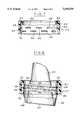
- FIG. 1is a side elevational view of a combined liquid containing and dispensing package embodying the invention.
- FIG. 2is a fragmentary sectional view taken along the line 2--2 in FIG. 3.
- FIG. 3is a fragmentary sectional view taken along the line 3--3 in FIG. 2.
- FIG. 4is a fragmentary sectional view on a greatly enlarged scale showing a portion of the package taken on the line 4--4 in FIG. 1.
- FIG. 5is a fragmentary view of a portion of the container.
- FIG. 6is a sectional view taken along the lines 6--6 in FIG. 5.
- FIG. 7is a fragmentary sectional view on an enlarged scale of a the portion of the spout insert.
- FIG. 8is a fragmentary sectional view on an enlarged scale of the spout insert.
- the combined liquid containing and dispensing the package embodying the inventioncomprises a hollow blow molded plastic container 20 that includes a spout insert 22 and a combined dispensing cup and closure 24.
- the plastic container 20has a finish 26 with an integrally formed series of lugs 28, 30 in two rows (FIG. 5) and a flat top sealing surface 32. Lugs 28 are staggered circumferentially with respect to lugs 30. As shown in FIG. 4, the lugs 28, 30 are formed by being blown outwardly so that complimentary recesses 34, 36 are provided on the inner surface of the finish.
- the spout insert 22includes an outer wall 38 and an inner wall 40 combined by an integral transverse wall 42.
- the outer wall 38is formed with two axially spaced rows of recesses 44, 46 that are complementary to and engage the lugs 28, 30 by a snap action to orient the spout insert 22 circumferentially.
- Such a constructionalso permits the assembly of the insert 22 to the container 20 at high speeds of assembly.
- the inner wall 40 of the spout insert 22includes a lower portion 48 that is connected to a spout portion 50 by an inclined bottom portion 52.
- the lower portion 48 of the spout insert 22is provided with axially spaced opening 54.
- the spout insert 22is further provided with a sealing rib 62 on the upper surface of transverse wall 42.
- the combined measuring cup and closureis substantially identical to the disclosures shown in U.S. Pat. No. 4,917,269 and includes a base wall 64 and a depending annular peripheral wall 66.
- a radial flange 68is provided intermediate the base wall on the lower edge of the wall 36 and external threads are provided below the flange.
- a primary flexible sealing ringis provided on the outer surface of the lower portion of the wall of the closure and extends at an angle outwardly and upwardly from the outer surface of the wall.
- a liquid containing and dispensing packagewherein the package can be easily assembled; wherein the part forming the spout can be inserted in the container and held in place utilizing various attaching methods; wherein the portion forming the spout can be pushed in and snapped in to place on the container; wherein the spout is radially prevented from rotating relative to the container, being removed from the container or taken off of the container by over-tightening of the closure; and where the combined measuring cup and closure seals against the spout and the spout seals against the container.
Landscapes
- Engineering & Computer Science (AREA)
- Mechanical Engineering (AREA)
- Closures For Containers (AREA)
Abstract
Description
Claims (18)
Priority Applications (1)
| Application Number | Priority Date | Filing Date | Title |
|---|---|---|---|
| US08/567,438US5649650A (en) | 1994-05-16 | 1995-12-05 | Liquid containing package with snap fit non-rotating spout insert |
Applications Claiming Priority (2)
| Application Number | Priority Date | Filing Date | Title |
|---|---|---|---|
| US24292394A | 1994-05-16 | 1994-05-16 | |
| US08/567,438US5649650A (en) | 1994-05-16 | 1995-12-05 | Liquid containing package with snap fit non-rotating spout insert |
Related Parent Applications (1)
| Application Number | Title | Priority Date | Filing Date |
|---|---|---|---|
| US24292394AContinuation | 1994-05-16 | 1994-05-16 |
Publications (1)
| Publication Number | Publication Date |
|---|---|
| US5649650Atrue US5649650A (en) | 1997-07-22 |
Family
ID=22916658
Family Applications (1)
| Application Number | Title | Priority Date | Filing Date |
|---|---|---|---|
| US08/567,438Expired - Fee RelatedUS5649650A (en) | 1994-05-16 | 1995-12-05 | Liquid containing package with snap fit non-rotating spout insert |
Country Status (1)
| Country | Link |
|---|---|
| US (1) | US5649650A (en) |
Cited By (18)
| Publication number | Priority date | Publication date | Assignee | Title |
|---|---|---|---|---|
| US6085949A (en)* | 1998-05-05 | 2000-07-11 | Liquid Container L.P. | Container with molded-in directional pour guide |
| US6209762B1 (en) | 1998-01-29 | 2001-04-03 | Owens-Illinois Closure Inc. | Dispensing package and method of use |
| US20010015054A1 (en)* | 1999-09-30 | 2001-08-23 | Caudle Timothy G. | Contoured pouch with pourable spout, and apparatus and process for producing same |
| US6601740B1 (en) | 1998-10-16 | 2003-08-05 | John Philip Clive | Closure device |
| US20030178450A1 (en)* | 2002-02-28 | 2003-09-25 | Schuessler Michael H. | Spout design |
| US20050092784A1 (en)* | 2003-10-28 | 2005-05-05 | Masterchem Industries, Inc. | Container spout |
| US20050188911A1 (en)* | 2004-03-01 | 2005-09-01 | Masterchem Industries, Inc. | Torque indicator |
| US7014078B2 (en) | 2001-12-05 | 2006-03-21 | Masterchem Industries Llc | Container |
| USD528917S1 (en)* | 2001-11-08 | 2006-09-26 | Johnsondiversey, Inc. | Bottle |
| US20070278256A1 (en)* | 2006-06-06 | 2007-12-06 | Law Brian R | Tamper-evident closure for a container |
| US20080142547A1 (en)* | 2006-12-13 | 2008-06-19 | Conopco, Inc., D/B/A Unilever | Liquids dispensing container with spouted fitment and anti-backoff and anti-rotation features |
| US20090101682A1 (en)* | 2005-06-15 | 2009-04-23 | Plastek Industries, Inc. | Pour Spout |
| US20090212073A1 (en)* | 2005-05-03 | 2009-08-27 | Haworth Brian D | Soap dispensing apparatus |
| US20100043910A1 (en)* | 2006-02-06 | 2010-02-25 | Plastek Industries, Inc. | Pour Spout |
| US20100187195A1 (en)* | 2009-01-28 | 2010-07-29 | Jamieson John E | Bottle With Directed Pour Spout |
| US20100213211A1 (en)* | 2009-02-26 | 2010-08-26 | Whaling Audrey M | Bottle Cap With Dosing and Pretreatment |
| CH704476A1 (en)* | 2011-02-15 | 2012-08-15 | Alpla Werke | Plastic container with a spout. |
| WO2017081543A1 (en)* | 2015-11-13 | 2017-05-18 | Helen Of Troy Limited | Bottle with modular handle and closure |
Citations (14)
| Publication number | Priority date | Publication date | Assignee | Title |
|---|---|---|---|---|
| DE1815685A1 (en)* | 1968-12-19 | 1970-06-25 | Elster & Co Ag | Connection pieces for the housing of flow devices |
| US4126338A (en)* | 1974-04-24 | 1978-11-21 | Badger Meter, Inc. | Threaded coupling |
| US4550862A (en)* | 1982-11-17 | 1985-11-05 | The Procter & Gamble Company | Liquid product pouring and measuring package with self draining feature |
| US4653676A (en)* | 1984-12-28 | 1987-03-31 | Gene Stull | Captive cap construction for hand-held dispenser |
| US4671421A (en)* | 1986-03-06 | 1987-06-09 | Owens-Illinois, Inc. | Plastic container |
| US4706829A (en)* | 1986-02-07 | 1987-11-17 | Owens-Illinois Closure Inc. | Liquid containing and dispensing package |
| US4863067A (en)* | 1988-02-25 | 1989-09-05 | Owens-Illinois Plastic Products Inc. | Plastic container with self-draining feature |
| US4887746A (en)* | 1986-10-14 | 1989-12-19 | The Procter & Gamble Company | Two-piece screw closure for containers |
| US4890768A (en)* | 1987-10-01 | 1990-01-02 | Owens-Illinois Plastic Products Inc. | Self draining container |
| US4890770A (en)* | 1987-06-17 | 1990-01-02 | Shiseido Company Limited | Dispensing and closing package for liquid products |
| US4917269A (en)* | 1989-05-10 | 1990-04-17 | Owens-Illinois Closure Inc. | Liquid containing and dispensing package |
| US5058772A (en)* | 1989-11-13 | 1991-10-22 | Phoenix Closures, Inc. | Dispenser closure with drain back feature |
| US5060827A (en)* | 1990-05-09 | 1991-10-29 | Colgate-Palmolive Company | Low profile anti-drip dosing cap and spout for liquid containers |
| US5275312A (en)* | 1991-10-10 | 1994-01-04 | Sofar Spa | One-way valve suitable for use in particular in a container supplying a liquid under pressure |
- 1995
- 1995-12-05USUS08/567,438patent/US5649650A/ennot_activeExpired - Fee Related
Patent Citations (14)
| Publication number | Priority date | Publication date | Assignee | Title |
|---|---|---|---|---|
| DE1815685A1 (en)* | 1968-12-19 | 1970-06-25 | Elster & Co Ag | Connection pieces for the housing of flow devices |
| US4126338A (en)* | 1974-04-24 | 1978-11-21 | Badger Meter, Inc. | Threaded coupling |
| US4550862A (en)* | 1982-11-17 | 1985-11-05 | The Procter & Gamble Company | Liquid product pouring and measuring package with self draining feature |
| US4653676A (en)* | 1984-12-28 | 1987-03-31 | Gene Stull | Captive cap construction for hand-held dispenser |
| US4706829A (en)* | 1986-02-07 | 1987-11-17 | Owens-Illinois Closure Inc. | Liquid containing and dispensing package |
| US4671421A (en)* | 1986-03-06 | 1987-06-09 | Owens-Illinois, Inc. | Plastic container |
| US4887746A (en)* | 1986-10-14 | 1989-12-19 | The Procter & Gamble Company | Two-piece screw closure for containers |
| US4890770A (en)* | 1987-06-17 | 1990-01-02 | Shiseido Company Limited | Dispensing and closing package for liquid products |
| US4890768A (en)* | 1987-10-01 | 1990-01-02 | Owens-Illinois Plastic Products Inc. | Self draining container |
| US4863067A (en)* | 1988-02-25 | 1989-09-05 | Owens-Illinois Plastic Products Inc. | Plastic container with self-draining feature |
| US4917269A (en)* | 1989-05-10 | 1990-04-17 | Owens-Illinois Closure Inc. | Liquid containing and dispensing package |
| US5058772A (en)* | 1989-11-13 | 1991-10-22 | Phoenix Closures, Inc. | Dispenser closure with drain back feature |
| US5060827A (en)* | 1990-05-09 | 1991-10-29 | Colgate-Palmolive Company | Low profile anti-drip dosing cap and spout for liquid containers |
| US5275312A (en)* | 1991-10-10 | 1994-01-04 | Sofar Spa | One-way valve suitable for use in particular in a container supplying a liquid under pressure |
Cited By (29)
| Publication number | Priority date | Publication date | Assignee | Title |
|---|---|---|---|---|
| US6209762B1 (en) | 1998-01-29 | 2001-04-03 | Owens-Illinois Closure Inc. | Dispensing package and method of use |
| US6085949A (en)* | 1998-05-05 | 2000-07-11 | Liquid Container L.P. | Container with molded-in directional pour guide |
| US6601740B1 (en) | 1998-10-16 | 2003-08-05 | John Philip Clive | Closure device |
| US20010015054A1 (en)* | 1999-09-30 | 2001-08-23 | Caudle Timothy G. | Contoured pouch with pourable spout, and apparatus and process for producing same |
| US6293073B1 (en) | 1999-09-30 | 2001-09-25 | Cryovac, Inc. | Apparatus for forming a pouch |
| USD528917S1 (en)* | 2001-11-08 | 2006-09-26 | Johnsondiversey, Inc. | Bottle |
| US7014078B2 (en) | 2001-12-05 | 2006-03-21 | Masterchem Industries Llc | Container |
| US7036693B2 (en) | 2001-12-05 | 2006-05-02 | Masterchem Industries Llc | Paint container |
| US7156265B2 (en) | 2001-12-05 | 2007-01-02 | Masterchem Industries Llc | Container |
| US7000808B2 (en)* | 2002-02-28 | 2006-02-21 | The Dial Corporation | Spout design |
| US20030178450A1 (en)* | 2002-02-28 | 2003-09-25 | Schuessler Michael H. | Spout design |
| US20050092784A1 (en)* | 2003-10-28 | 2005-05-05 | Masterchem Industries, Inc. | Container spout |
| US7841489B2 (en) | 2003-10-28 | 2010-11-30 | Masterchem Industries, Llc | Container sealing system |
| US20070272706A1 (en)* | 2003-10-28 | 2007-11-29 | Gilbertson Mark A | Container Sealing System |
| US20050188911A1 (en)* | 2004-03-01 | 2005-09-01 | Masterchem Industries, Inc. | Torque indicator |
| US8261945B2 (en)* | 2005-05-03 | 2012-09-11 | Diversey, Inc. | Soap dispensing apparatus |
| US20090212073A1 (en)* | 2005-05-03 | 2009-08-27 | Haworth Brian D | Soap dispensing apparatus |
| US20090101682A1 (en)* | 2005-06-15 | 2009-04-23 | Plastek Industries, Inc. | Pour Spout |
| US20100043910A1 (en)* | 2006-02-06 | 2010-02-25 | Plastek Industries, Inc. | Pour Spout |
| US20070278256A1 (en)* | 2006-06-06 | 2007-12-06 | Law Brian R | Tamper-evident closure for a container |
| US20080142547A1 (en)* | 2006-12-13 | 2008-06-19 | Conopco, Inc., D/B/A Unilever | Liquids dispensing container with spouted fitment and anti-backoff and anti-rotation features |
| US20100187195A1 (en)* | 2009-01-28 | 2010-07-29 | Jamieson John E | Bottle With Directed Pour Spout |
| US20100213211A1 (en)* | 2009-02-26 | 2010-08-26 | Whaling Audrey M | Bottle Cap With Dosing and Pretreatment |
| CH704476A1 (en)* | 2011-02-15 | 2012-08-15 | Alpla Werke | Plastic container with a spout. |
| WO2012110059A1 (en)* | 2011-02-15 | 2012-08-23 | Alpla Werke Alwin Lehner Gmbh & Co. Kg | Plastic container having a pouring spout |
| CN103415442A (en)* | 2011-02-15 | 2013-11-27 | 阿尔温莱纳股份有限两合公司阿尔普拉工厂 | Plastic container with pour |
| RU2555666C2 (en)* | 2011-02-15 | 2015-07-10 | Альпла Верке Альвин Ленер Гмбх Унд Ко. Кг | Plastic vessel with outlet nozzle |
| CN103415442B (en)* | 2011-02-15 | 2015-07-22 | 阿尔温莱纳股份有限两合公司阿尔普拉工厂 | Plastic container with pour |
| WO2017081543A1 (en)* | 2015-11-13 | 2017-05-18 | Helen Of Troy Limited | Bottle with modular handle and closure |
Similar Documents
| Publication | Publication Date | Title |
|---|---|---|
| US5649650A (en) | Liquid containing package with snap fit non-rotating spout insert | |
| EP1371571B1 (en) | Jig for holding an inner plug	 | |
| US4230230A (en) | Plastic overcap for bottle package | |
| US3124281A (en) | stull | |
| US4635823A (en) | Dispensing closure construction | |
| US6056144A (en) | Beverage cup with locking lid | |
| EP0369559B1 (en) | Closure assembly with pouring spout and measuring cup | |
| US5078288A (en) | Child resistant spout package | |
| US4638916A (en) | Closure with snap-type hinge cap | |
| US4917269A (en) | Liquid containing and dispensing package | |
| US5285912A (en) | Snap on pull off tamper indicating flexible cap and neck configuration | |
| US5388712A (en) | Squeeze bottle top with integral closure holder | |
| CA1334953C (en) | Child resistant dispensing closure | |
| US4106672A (en) | Resealable end closure having plural openings | |
| US5373955A (en) | Neck finish for a wide mouth container | |
| US5284265A (en) | Non-replaceable snap on cap for school milk bottles | |
| EP0709301A2 (en) | Tamper indicating resealable closure for a container | |
| US6260721B1 (en) | Plastic cap | |
| US3434637A (en) | Fitting for containers | |
| US6595395B2 (en) | Dispenser having a fixing member, and a fixing member for such a dispenser | |
| KR930009876A (en) | Snap Hinge Caps on Dispensing Container | |
| US20210269203A1 (en) | Closure | |
| US7028858B2 (en) | Quick-twist pop-off closure | |
| US5727703A (en) | Child resistant package utilizing one piece closure | |
| US4187964A (en) | Combined closure cap and pour-out fitment |
Legal Events
| Date | Code | Title | Description |
|---|---|---|---|
| FPAY | Fee payment | Year of fee payment:4 | |
| FPAY | Fee payment | Year of fee payment:8 | |
| AS | Assignment | Owner name:DEUTSCHE BANK AG CAYMAN ISLANDS BRANCH AS SECOND-L Free format text:GRANT OF SECURITY INTEREST;ASSIGNOR:GRAHAM PACKAGING COMPANY, L.P.;REEL/FRAME:015552/0299 Effective date:20041007 Owner name:DEUTSCHE BANK AG CAYMAN ISLANDS BRANCH, NEW JERSEY Free format text:GRANT OF SECURITY INTEREST;ASSIGNOR:GRAHAM PACKAGING COMPANY, L.P.;REEL/FRAME:015980/0213 Effective date:20041007 | |
| AS | Assignment | Owner name:GRAHAM PACKAGING COMPANY, L.P., PENNSYLVANIA Free format text:PATENT RELEASE;ASSIGNOR:DEUTSCHE BANK AG, CAYMAN ISLANDS BRANCH, AS COLLATERAL AGENT;REEL/FRAME:019140/0509 Effective date:20070330 | |
| REMI | Maintenance fee reminder mailed | ||
| LAPS | Lapse for failure to pay maintenance fees | ||
| STCH | Information on status: patent discontinuation | Free format text:PATENT EXPIRED DUE TO NONPAYMENT OF MAINTENANCE FEES UNDER 37 CFR 1.362 | |
| FP | Lapsed due to failure to pay maintenance fee | Effective date:20090722 | |
| AS | Assignment | Owner name:GRAHAM PACKAGING COMPANY, L.P., PENNSYLVANIA Free format text:RELEASE OF SECURITY INTERESTS;ASSIGNOR:DEUTSCHE BANK AG, GAYMAN ISLANDS BRANCH, AS COLLATERAL AGENT;REEL/FRAME:027011/0572 Effective date:20110908 | |
| AS | Assignment | Owner name:GRAHAM PACKAGING COMPANY, L.P., PENNSYLVANIA Free format text:RELEASE OF SECURITY INTEREST IN CERTAIN PATENT COLLATERAL;ASSIGNOR:DEUTSCHE BANK AG CAYMAN ISLANDS BRANCH, AS COLLATERAL AGENT AND GRANTEE;REEL/FRAME:053414/0001 Effective date:20200805 |