US5648982A - Spread spectrum transmitter - Google Patents
Spread spectrum transmitterDownload PDFInfo
- Publication number
- US5648982A US5648982AUS08/304,091US30409194AUS5648982AUS 5648982 AUS5648982 AUS 5648982AUS 30409194 AUS30409194 AUS 30409194AUS 5648982 AUS5648982 AUS 5648982A
- Authority
- US
- United States
- Prior art keywords
- signal
- chip
- spread spectrum
- code
- sequence
- Prior art date
- Legal status (The legal status is an assumption and is not a legal conclusion. Google has not performed a legal analysis and makes no representation as to the accuracy of the status listed.)
- Expired - Lifetime
Links
- 238000001228spectrumMethods0.000titleclaimsabstractdescription122
- 238000000034methodMethods0.000claimsabstractdescription46
- 230000005540biological transmissionEffects0.000claimsabstractdescription39
- 238000004891communicationMethods0.000claimsdescription29
- 230000004044responseEffects0.000claimsdescription16
- 230000007704transitionEffects0.000claimsdescription14
- 230000002596correlated effectEffects0.000abstractdescription2
- 230000001427coherent effectEffects0.000description62
- 238000010586diagramMethods0.000description37
- 230000000875corresponding effectEffects0.000description14
- 239000003990capacitorSubstances0.000description8
- 238000001914filtrationMethods0.000description7
- 230000001413cellular effectEffects0.000description6
- 230000000694effectsEffects0.000description6
- 230000008859changeEffects0.000description5
- 230000003111delayed effectEffects0.000description5
- 238000013139quantizationMethods0.000description5
- 230000001419dependent effectEffects0.000description4
- 230000006870functionEffects0.000description4
- 238000010897surface acoustic wave methodMethods0.000description4
- 230000001360synchronised effectEffects0.000description4
- 230000003321amplificationEffects0.000description3
- 230000035559beat frequencyEffects0.000description3
- 230000008901benefitEffects0.000description3
- 238000003199nucleic acid amplification methodMethods0.000description3
- 230000010363phase shiftEffects0.000description3
- 230000007423decreaseEffects0.000description2
- 239000010931goldSubstances0.000description2
- 230000008569processEffects0.000description2
- 230000007480spreadingEffects0.000description2
- 230000018199S phaseEffects0.000description1
- 230000010267cellular communicationEffects0.000description1
- 230000000295complement effectEffects0.000description1
- 230000003750conditioning effectEffects0.000description1
- 230000001276controlling effectEffects0.000description1
- 239000013078crystalSubstances0.000description1
- 230000001934delayEffects0.000description1
- 230000003467diminishing effectEffects0.000description1
- 238000004870electrical engineeringMethods0.000description1
- 230000010354integrationEffects0.000description1
- 230000000737periodic effectEffects0.000description1
- 230000011664signalingEffects0.000description1
- 230000003595spectral effectEffects0.000description1
- 238000002604ultrasonographyMethods0.000description1
Images


Classifications
- H—ELECTRICITY
- H04—ELECTRIC COMMUNICATION TECHNIQUE
- H04B—TRANSMISSION
- H04B1/00—Details of transmission systems, not covered by a single one of groups H04B3/00 - H04B13/00; Details of transmission systems not characterised by the medium used for transmission
- H04B1/69—Spread spectrum techniques
- H04B1/707—Spread spectrum techniques using direct sequence modulation
- H04B1/7073—Synchronisation aspects
- H04B1/7075—Synchronisation aspects with code phase acquisition
- H04B1/708—Parallel implementation
- H—ELECTRICITY
- H04—ELECTRIC COMMUNICATION TECHNIQUE
- H04B—TRANSMISSION
- H04B1/00—Details of transmission systems, not covered by a single one of groups H04B3/00 - H04B13/00; Details of transmission systems not characterised by the medium used for transmission
- H04B1/69—Spread spectrum techniques
- H04B1/707—Spread spectrum techniques using direct sequence modulation
- H—ELECTRICITY
- H04—ELECTRIC COMMUNICATION TECHNIQUE
- H04J—MULTIPLEX COMMUNICATION
- H04J13/00—Code division multiplex systems
- H04J13/10—Code generation
- H—ELECTRICITY
- H04—ELECTRIC COMMUNICATION TECHNIQUE
- H04L—TRANSMISSION OF DIGITAL INFORMATION, e.g. TELEGRAPHIC COMMUNICATION
- H04L27/00—Modulated-carrier systems
- H04L27/18—Phase-modulated carrier systems, i.e. using phase-shift keying
- H04L27/20—Modulator circuits; Transmitter circuits
- H04L27/2003—Modulator circuits; Transmitter circuits for continuous phase modulation
- H04L27/2007—Modulator circuits; Transmitter circuits for continuous phase modulation in which the phase change within each symbol period is constrained
- H04L27/2014—Modulator circuits; Transmitter circuits for continuous phase modulation in which the phase change within each symbol period is constrained in which the phase changes in a piecewise linear manner during each symbol period, e.g. minimum shift keying, fast frequency shift keying
- H—ELECTRICITY
- H04—ELECTRIC COMMUNICATION TECHNIQUE
- H04L—TRANSMISSION OF DIGITAL INFORMATION, e.g. TELEGRAPHIC COMMUNICATION
- H04L27/00—Modulated-carrier systems
- H04L27/18—Phase-modulated carrier systems, i.e. using phase-shift keying
- H04L27/22—Demodulator circuits; Receiver circuits
- H04L27/227—Demodulator circuits; Receiver circuits using coherent demodulation
- H04L27/2275—Demodulator circuits; Receiver circuits using coherent demodulation wherein the carrier recovery circuit uses the received modulated signals
- H04L27/2278—Demodulator circuits; Receiver circuits using coherent demodulation wherein the carrier recovery circuit uses the received modulated signals using correlation techniques, e.g. for spread spectrum signals
- H—ELECTRICITY
- H04—ELECTRIC COMMUNICATION TECHNIQUE
- H04L—TRANSMISSION OF DIGITAL INFORMATION, e.g. TELEGRAPHIC COMMUNICATION
- H04L27/00—Modulated-carrier systems
- H04L27/18—Phase-modulated carrier systems, i.e. using phase-shift keying
- H04L27/22—Demodulator circuits; Receiver circuits
- H04L27/233—Demodulator circuits; Receiver circuits using non-coherent demodulation
- H04L27/2332—Demodulator circuits; Receiver circuits using non-coherent demodulation using a non-coherent carrier
- H—ELECTRICITY
- H04—ELECTRIC COMMUNICATION TECHNIQUE
- H04B—TRANSMISSION
- H04B1/00—Details of transmission systems, not covered by a single one of groups H04B3/00 - H04B13/00; Details of transmission systems not characterised by the medium used for transmission
- H04B1/69—Spread spectrum techniques
- H04B1/707—Spread spectrum techniques using direct sequence modulation
- H04B1/709—Correlator structure
- H04B1/7093—Matched filter type
- H—ELECTRICITY
- H04—ELECTRIC COMMUNICATION TECHNIQUE
- H04B—TRANSMISSION
- H04B2201/00—Indexing scheme relating to details of transmission systems not covered by a single group of H04B3/00 - H04B13/00
- H04B2201/69—Orthogonal indexing scheme relating to spread spectrum techniques in general
- H04B2201/707—Orthogonal indexing scheme relating to spread spectrum techniques in general relating to direct sequence modulation
- H04B2201/70701—Orthogonal indexing scheme relating to spread spectrum techniques in general relating to direct sequence modulation featuring pilot assisted reception
- H—ELECTRICITY
- H04—ELECTRIC COMMUNICATION TECHNIQUE
- H04J—MULTIPLEX COMMUNICATION
- H04J14/00—Optical multiplex systems
- H04J14/005—Optical Code Multiplex
Definitions
- This inventionrelates to spread spectrum communication, and to modulating and demodulating continuous phase modulated (CPM) spread spectrum signals.
- CPMcontinuous phase modulated
- Spread spectrumis a type of signal modulation that spreads a signal to be transmitted over a bandwidth that substantially exceeds the data-transfer rate, hence the term "spread spectrum".
- a data signalis modulated with a pseudo-random chip sequence; the encoded spread spectrum signal is transmitted to the receiver which despreads the signal.
- BPSKbiphase shift keying
- CPMcontinuous phase modulated
- MSKMinimum shift keying
- the receiverIn despreading a spread spectrum signal, the receiver produces a correlation pulse in response to the received spread spectrum signal when the received spread spectrum signal matches the chip sequence to a predetermined degree.
- Various techniquesare available for correlating the received signal with the chip sequence, including those using surface acoustic wave (SAW) correlators, tapped delay line (TDL) correlators, serial correlators, and others.
- SAWsurface acoustic wave
- TDLtapped delay line
- CPM techniquesare often chosen so as to preserve signal bandwidth of the spread spectrum signal when it is amplified and transmitted.
- CPM techniquesalso has the advantage that "class C" amplifiers may be used for transmitting the spread spectrum signal.
- spread spectrum signals transmitted using CPMare difficult to decode with many types of spread spectrum correlators, including various SAW correlators and serial correlators. These types of correlators usually require a BPSK spread spectrum signal for effective correlation rather than an MSK or other CPM spread spectrum signal because a BPSK signal has either a zero or 180 degree phase shift for each chip time.
- each chip of a received BPSK signalmay be compared with each chip of the spread spectrum code, and a maximum correlation pulse may be generated when a predetermined number of matches occur.
- the correlation pulsewill generally be very weak and may be quite difficult to detect.
- a coherent reference signal in this sensemay be defined as a locally generated signal that matches the transmitter carrier signal in frequency and phase.
- the receivermay use the locally generated reference signal to demodulate the received signal.
- a local reference signal generated in the receiverwill usually be of a non-coherent variety--that is, having small differences in frequency and phase from the transmitter's carrier signal. These frequency and phase differences are not constant but vary over time.
- a particular non-coherent digital matched filteris described in A. Baier and P. W. Baier, "Digital Matched Filtering of Arbitrary Spread-Spectrum Waveforms Using Correlators with Binary Quantization," 2 Proceedings, 1983 IEEE Military Communications Conference, Vol. 2, pp. 418-423 (1983).
- the digital filter described thereinuses four real filter channels to perform four-phase quantization in the complex plane, with the four quadrants being the quantization regions, and the result taking on the four complex values of ⁇ 1 ⁇ j.
- an input signalis divided into an in-phase signal and a quadrature signal.
- the in-phase signal and the quadrature signalare separately filtered, sampled and digitized using 1-bit quantization.
- the quantized in-phase signal and the quantized quadrature signalare each fed into two binary correlators each programmed with a reference sequence of N chips, one chip for each sample.
- the outputs of the four binary correlatorsare combined to produce a resultant output signal.
- Baier's four-phase digital matched filteris also described in A. Baier, "A Low-Cost Digital Matched Filter for Arbitrary Constant-Envelope Spread Spectrum Waveforms," IEEE Transactions on Communications, Vol. Com-32, No. 4, April 1984, pp. 354-361.
- the inventioncomprises a method and apparatus for modulating and demodulating CPM spread spectrum signals that can be used with a wide variety of correlators in an effective manner.
- a transmitterdivides the signal data stream into a plurality of data streams (e.g., an I and Q data stream), independently modulates the data streams using CPM or a related modulation technique, and superposes the plurality of resultants for transmission.
- a preferred receiverreceives the superposed spread spectrum signal, simultaneously attempts to correlate for a plurality of chip sequences (such as I and Q chip sequences), and interleaves the correlated data streams into a unified signal data stream.
- the receivercomprises a carrier signal that is neither frequency matched or phase matched with the transmitted signal.
- the receiverseparates the received spread spectrum signal into real and imaginary parts, attempts to correlate both real and imaginary parts for a plurality of chip sequences (e.g., I and Q chip sequences), and combines the real and imaginary signals into a unified signal data stream.
- chip sequencese.g., I and Q chip sequences
- a presently preferred embodiment of this aspect of the inventionuses a single bit digitization of the received spread spectrum signal to preserve only phase information for inexpensive digital processing.
- the receiveruses self-synchronization of the received spread spectrum signal for despreading and correlation.
- a preferred receiverseparates the received spread spectrum signal into real and imaginary parts, correlates both real and imaginary parts for a plurality of chip sequences using self-synchronization techniques, and combines the real and imaginary self-synchronized signals into a unified signal data stream.
- a preferred transmittercomprises a plurality of lookup tables for storing spread spectrum code chip sequences, at least one preamble code chip sequence, and at least one fill code chip sequence.
- An output from each of the tablesis provided to a selection circuit (e.g., a multiplexer) that selects, under control of a controller, chips from each of the tables to construct a unified chip sequence.
- the unified chip sequenceis divided into a stream of odd chips and a stream of even chips, which are provided to separate waveform generators.
- An output from each waveform generatoris combined and modulated as a continuous phase modulation signal.
- FIG. 1is a block diagram of a spread spectrum communication transmitter and receiver as known in the art.
- FIG. 2depicts a pattern of cells for use in spread spectrum communication.
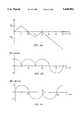
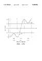
- FIG. 3is a graph of phase changes over time for an MSK signal.
- FIGS. 4A-4Care a set of graphs showing a relationship among phase components.
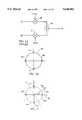
- FIG. 5Ais a block diagram showing means for generating a CPM spread spectrum signal.
- FIG. 5Bis a graph of I and Q values.
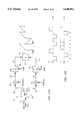
- FIG. 6is a block diagram of a spread spectrum transmitter.
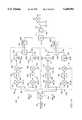
- FIG. 7is a block diagram of an embodiment of spread spectrum receiver.
- FIG. 8is a block diagram showing another embodiment of a spread spectrum receiver.
- FIG. 9is a scatter diagram comparing transmitted and received I and Q signals.
- FIG. 10is a block diagram of an embodiment of a spread spectrum receiver using separable real and imaginary parts of a received spread spectrum signal.
- FIGS. 11A-11Fare diagrams showing a representation of transmitted and received waveforms for different phase values.
- FIG. 12is a block diagram of another embodiment of a spread spectrum receiver using separable real and imaginary parts of a received spread spectrum signal.
- FIGS. 13A-13Bis a block diagram of an embodiment of a spread spectrum receiver using serial correlation.
- FIG. 14is a block diagram of an embodiment of spread spectrum receiver using serial correlation for separable real and imaginary parts of the received spread spectrum signal.
- FIG. 15is a block diagram of another embodiment of a spread spectrum receiver using serial correlation for separable real and imaginary parts of the received spread spectrum signal.
- FIG. 16is a block diagram of an embodiment of spread spectrum receiver using self-synchronized correlation for separable real and imaginary parts of the received spread spectrum signal.
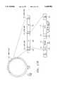
- FIGS. 17A and 17Bare block diagrams of a preferred transmitter and a preferred transmission protocol, respectively.
- FIG. 17Cis an exemplary SQAM waveform generated by a transmitter using separate I and Q components.
- FIG. 18is a block diagram of a preferred non-coherent matched filter and associated receiver components.
- FIG. 19is a block diagram of a preferred digital circuit embodiment of a set of noncoherent serial correlators and associated receiver components.
- FIG. 20is a diagram showing exemplary correlation pulses within a predetermined timing window.
- FIGS. 21A and 21Bare schematic diagrams showing a preferred digital circuit embodiment of part of a receiving system used in conjunction with the circuitry of FIGS. 18 and 19.
- FIG. 22is a block diagram of a Robertson device for computing a sum of the squares of its inputs.
- FIG. 23is a block diagram of a correlator matched to a specific code sequence.
- FIG. 1is a block diagram of a spread spectrum communication transmitter 101 and receiver 108 as known in the art.
- the spread spectrum transmitter 101 of FIG. 1comprises an input port 102 for input data 103, a transmitter chip sequence generator 104, and a modulator 105.
- the transmitter 101thereby transmits a spread spectrum signal 106 over a transmission channel 107.
- the transmission channel 107may comprise an RF channel, but may also comprise other transmission media, such as modulated laser, ultrasound, or fluidic systems.
- the spread spectrum receiver 108 of FIG. 1comprises a receiver chip sequence generator 110, a demodulator 111, and an output port 112 for generating output data 113.
- a single chip sequencewhich appears essentially random to others not knowing the spreading code upon which it is based, may be identically generated by both the transmitter generator 104 and the receiver generator 110.
- An extensive discussion of spread spectrum communication, spreading codes, and chip sequencesmay be found in R. Dixon, Spread Spectrum Systems with Commercial Applications (J. Wiley & Sons, 3d ed. 1994).
- FIG. 2depicts a pattern of cells for use in spread spectrum communication.
- a region 151 for communicationmay be divided into a set of cells 152, each of which may be assigned a frequency and a set of spread spectrum codes for communication.
- a first cell 153may generally be found adjacent to a set of distance-one neighbors 154 and a set of distance-two neighbors 155.
- a plurality of frequencies f1, f2 and f3, and a plurality of code sets c1, c2, and c3,may be configured in a pattern of cells 152 so that the no distance-one neighbors 154 or distance-two neighbors 155 of a particular cell 153 has the same combination of frequency and code set as the cell 153.
- CPM spread spectrum signalsinclude several variations; these include minimum shift keying (MSK) and its variations, e.g., Gaussian pre-filtered MSK (GMSK), superposed quadrature amplitude modulation (SQAM), and staggered quadrature offset raised cosine modulation (SQORC). These variations are known in the art. Explanations of various types of CPM techniques may be found in the following: Frank Amoroso and James A. Kivett, "Simplified MSK Signaling Technique," IEEE Transactions on Communications, April 1977, pp. 433-441; Mark C. Austin and Ming U. Chang, “Quadrature Overlapped Raised-Cosine Modulation,” IEEE Transactions on Communications, Vol. Com-29, No.
- MSKminimum shift keying
- GMSKGaussian pre-filtered MSK
- SQAMsuperposed quadrature amplitude modulation
- SQLORCstaggered quadrature offset raised cosine modulation
- An MSK signalis generally characterized by the fact that phase changes linearly within each chip time, and that the phase change over a single chip time is ⁇ /2 radians ( ⁇ 90 degrees).
- the rate of phase change for a single chip timeis ⁇ k, for a suitable value k, and is linear and continuous everywhere except at chip boundaries.
- FIG. 3is a graph showing possible changes in phase for an MSK signal over time.
- the x-axisis time and the y-axis is signal phase.
- the phase ⁇ (t)changes from 0 to ⁇ /2 or - ⁇ /2.
- the phase ⁇ (t)changes from + ⁇ /2 to 0 or + ⁇ /2 to + ⁇ , or from - ⁇ /2 to 0 or - ⁇ /2 to - ⁇ , and so on.
- An MSK signal s(t)may be considered to comprise two offset signals, i(t) and q(t), which represent the phase of the carrier signal. At any instant of time the phase of the carrier signal may be expressed as:
- FIGS. 4A-4CSince the phase of the MSK signal varies linearly from one chip time to the next chip time, i(t) and q(t) may consist of half sinusoidal waveforms as shown in the FIGS. 4A-4C.
- the x-axisis time and the y-axis is signal phase.
- FIG. 4Ais a graph showing an example of how the phase ⁇ (t) may change for a particular MSK signal in each chip time from 0, Tc, 2Tc, 3Tc, 4Tc, 5Tc, and so on, for the chip sequence "11101001 . . . "
- the phasevaries for an MSK signal by ⁇ /2 in either a positive or negative direction.
- 4B and 4Care graphs showing i(t) and q(t) waveforms, respectively, which correspond to the varying phase ⁇ (t).
- the i(t) signalcomprises a sequence of partial cosine waveforms
- the q(t) signalcomprises a sequence of partial sine waveforms.
- Each of i(t) and q(t)comprises a half-waveform over a timespan of 2Tc; that is, i(t) and q(t) occur at half the chip rate.
- An i(t) waveform and a q(t) waveformcan be generated from a chip stream c(t) and combined so as to produce an MSK signal--i.e., a signal having a phase which varies linearly as desired in either a positive or a negative direction by an amount of ⁇ /2 each chip time.
- the original chip stream c(t)may be demultiplexed into two separate chip streams C even (t) and C odd (t), each having half the chip rate of the original chip stream c(t).
- the i(t) signalis associated with the odd-numbered chips
- the q(t) signalis associated with the even-numbered chips.
- the i(t) signalcomprises a sequence of half-sinusoidal waveforms, one for each odd chip.
- Each half sinusoldmay be positive for a "1" chip and negative for a "0" chip:
- C odd (t)comprises the odd-numbered chips from the chip stream to be transmitted.
- the q(t) signalcomprises a sequence of half-sinusoidal waveforms, one for each even chip:
- C even (t)comprises the even-numbered chips from the chip stream to be transmitted.
- the i(t) and q(t) signalsmay be used to modulate a carrier signal operating at frequency ⁇ 0 by summing i(t) and q(t) in phase quadrature so as to generate an MSK signal s(t) having a linearly varying phase ⁇ (t).
- a block diagram showing means for generating a CPM spread spectrum signalis depicted in FIG. 5A.
- the signal i(t)is multiplied with a signal A cos ⁇ 0 t by multiplier 250, which provides an output to a summer 252.
- the signal q(t)is multiplied with a signal A sin ⁇ 0 t by multiplier 251, which also provides an output to the summer 252.
- the summer 252sums its inputs and produces an output signal s(t).
- i(t) and q(t)each comprises every other chip from the chip stream c(t); i(t) comprises the odd-numbered chips 1, 3, 5, . . . ; q(t) comprises the even-numbered chips 2, 4, 6 . . .
- the transmitted signal s(t), generated from signals i(t) and q(t),therefore comprises all of the chips. Because q(t) is derived from the even chips while i(t) is derived from the odd chips, q(t) is delayed by one chip time from i(t); thus, q(t) and i(t) are offset signals.
- FIG. 5Bis a graph of I and Q values, in which the x-axis represents values of i(t) and the y-axis represents values of q(t). Each ⁇ i(t), q(t)> pair falls at a given instant of time on the circle 260.
- GMSK, SQAM, or SQORCdiffer from MSK in that phase changes of less than ⁇ /2 are allowed.
- GMSK, SQAM, and SQORCall use a form of pre-filtering the MSK i(t) and q(t) signals to reduce transmission bandwidth.
- This pre-filteringhas the general effect of reducing the high-frequency components generated by the sharp phase reversals in the MSK i(t) and q(t) signals.
- pre-filteringmay also result in intersymbol interference over several chip times, the effect of which may be mitigated with a trellis decoder.
- SQAM or SQORCthe final frequency envelope is no longer constant, but is still nearly so.
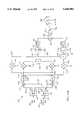
- FIG. 6is a block diagram of a spread spectrum transmitter.
- a chip stream c(t) 301is provided to a demultiplexer 302, which divides the chip stream 301 into a set of odd chips C odd (t) 303 for the i(t) signal and a set of even chips C even (t) 304 for the q(t) signal.
- the chip stream c(t) 301may comprise the result of a pseudo-noise ("PN") code modulated with a data stream (as in direct sequence spread spectrum communication), or may comprise a sequence of chip codes corresponding to predetermined symbols such as may be done, for example, in code shift keying (CSK) techniques.
- PNpseudo-noise
- the odd chips 303 and the even chips 304are each coupled to first and second waveform generators P(t) 305 and 306 respectively.
- the waveform generators P(t)may generate a half-sinusoidal waveform, positive or negative, as described herein.
- Other waveform generators and other waveformsare within the scope and spirit of the invention.
- the output of the first waveform generator 305corresponds to the signal i(t) and is coupled to a first multiplier 307, which modulates a carrier signal cos w 0 t to generate a signal s 1 (t) 308 corresponding to i(t) cos w 0 t.
- the output of the second waveform generator 306corresponds to the signal q(t), which, as mentioned, is delayed by one chip time Tc from the signal i(t).
- the output of the second waveform generator 306is coupled to a second multiplier 310, which modulates a carrier signal sin w 0 t to generate a signal s 2 (t) 311 corresponding to q(t) sin w 0 t.
- the signals s 1 (t) 308 and s 2 (t) 311are coupled to a summer 312, which combines its inputs and generates a superposed signal s(t) 313.
- the signal s(t)may be amplified and transmitted by a transmission system, such as a radio transmission system, coupled to the transmission channel 107.
- the chip stream c(t)may be generated by modulating a pseudo-noise code with data to be transmitted such as is known in direct sequence spread spectrum modulation.
- the chip stream c(t)comprises a plurality of symbol codes, each symbol code representing a symbol indicative of one or more data bits of information.
- sequences of data bitsare translated into symbols which are used to select from a plurality of symbol codes located in a table. For example, five data bits may represent a symbol; thus, there may be 32 possible symbols representing all possible combinations of five data bits.
- Each symbolis associated with a unique symbol code, so that thirty-two symbol codes (or sixteen symbol codes and their inverses) may represent all possible symbols. For each symbol to be transmitted, the appropriate symbol code is selected among the thirty-two available.
- the chip stream c(t)may comprise a sequence of symbol codes.
- Each symbol codemay be, for example, 32 chips in length, or some other appropriate number of chips in length (preferably an even number of chips).
- the demultiplexer 302may comprise a table of half symbol codes.
- the demultiplexer 302may comprise a Q-lookup table and I-lookup table. For every five bits of data to be transmitted (following the previous example), instead of looking up a symbol code from a table and demultiplexing it with demultiplexer 302, two half symbol codes may be read, one from the I-lookup table and one from the Q-lookup table. Each half symbol code may be clocked serially to the waveform generators 305, 306 for further processing.
- the systemmay comprise clocking logic which provides a delay of one chip time Tc to the half symbol code from the Q-lookup table.
- the contents of the I-lookup table and Q-lookup tablecan be generated by dividing each symbol code into even and odd chips, and using the even chips for the half symbol codes in the Q-lookup table and the odd chips for the half symbol codes in the I-lookup table.
- Other techniques for generating even and odd chip sequences suitable for signals q(t) and i(t)fall within the spirit and scope of the invention.
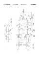
- FIG. 7is a block diagram of a spread spectrum receiver.
- the transmitted signal s(t) 313may undergo attenuation, addition of noise, multipath superposition, and other known and unknown effects of the transmission channel 107. Accordingly, the received signal s*(t) 401 may differ from the transmitted signal s(t) 313 in known and unknown ways.
- Received signal s*(t)may be despread using multiple correlators keyed to I and Q chip streams. Because CPM spread spectrum signals may be thought of as the superposition of time staggered signals created from I and Q chip streams (each at half the chip rate), a receiver according to one embodiment of the present invention uses two correlators, one programmed with the I-chip-sequence and one programmed with the Q-chip-sequence and both operating at half the chip rate, to decode the received signal, and then combines the outputs of the two correlators.
- the received signal s*(t) 401is coupled to a CPM correlator 402 for recognizing a chip sequence in the received signal s*(t) 401.
- the CPM correlator 402comprises a power divider 403 for generating duplicate signals, an i*(t) signal 404 with a 0 degree phase delay, and a q*(t) signal 405 with a 90 degree phase shift.
- the i*(t) signal 404is coupled to a delay 406, which delays the i*(t) signal 404 by one chip time Tc to allow simultaneous generation of correlation pulses by the I correlator 407 and the Q correlator 409.
- the delayed i*(t) signalis coupled to an I correlator 407, and the q*(t) signal 405 is coupled directly to a Q correlator 409.
- the I correlator 407operates at a chip rate of Rc/2, where Rc is the chip rate (i.e., 1/Tc) of the received signal s*(t) 401.
- the I correlator 407may comprise one of several types of correlators, e.g., a surface-acoustical-wave (SAW) correlator, a tapped-delay-line (TDL) correlator, or a serial correlator. Examples of suitable correlators may be found in U.S. Pat. No. 5,016,255 entitled "Asymmetric Spread Spectrum Correlator" or in U.S. Pat. No.
- the I correlator 407produces an output I correlation signal 408 indicating a degree of match between the delayed i*(t) signal and a predetermined I-chip-sequence.
- the Q correlator 409similarly operates at a chip rate of Rc/2, and may similarly comprise any of a number of suitable correlators such as those described in the patents referenced in the preceding paragraph.
- the Q correlator 409produces an output Q correlation signal 410 indicating a degree of match between the q*(t) signal and a predetermined Q-chip-sequence.
- the I correlation signal 408 and the Q correlation signal 410are coupled to a summer 411, which combines its inputs and produces a unified correlation signal 412. Because the i*(t) signal is delayed by delay 406, the I correlation signal 408 and Q correlation signal 410 occur simultaneously.
- the unified correlation signal 412is used to determine a data stream d(t) from which the chip sequence c(t) was generated.
- the I correlator 407 and the Q correlator 409thus jointly identify the chip sequence in the received signal s*(t) 401.
- the I correlator 407is configured to recognize the odd chips of the chip sequence
- the Q correlator 409is configured to recognize the even chips of the chip sequence.
- the sum of the I correlation signal 408 and the Q correlation signal 410is at a maximum, and may be compared against a predetermined threshold to allow recognition of the chip sequence.
- a unified correlation signal 412is produced when a chip sequence is recognized.
- a systemmay be configured so as to have a plurality (e.g., 32) of CPM correlators 402 operating in parallel, each tuned to recognize a different code sequence.
- the outputs of all 32 CPM correlatorsmay be summed and, when the sum is at a predetermined maximum level, the CPM correlator 402 with the highest magnitude output may be chosen by a best-of-M detector or similar means as indicative of the data stream d(t).
- each of 32 CPM correlatorsmay attempt in parallel to recognize a code sequence, and the one with the highest magnitude correlation signal may be assumed to indicate the received chip stream.
- the recognized chip streammay correspond to a data symbol from which a portion of the data stream d(t) may be recovered.
- each data bit or data symbol of the data stream d(t)may be encoded by modulation with the entire length of a pseudo random chip sequence generated from a chip sequence code. For example, if a chip sequence code identifies a pseudo random chip sequence that repeats after 32 chips, each data bit of the data stream d(t) may be modulated with all 32 of those chips.
- the CPM correlator 402may be used with those particular techniques.
- the CPM correlatormay be used with other spread spectrum techniques to recognize a correlation signal that is used to synchronize the transmitter 101 and the receiver 108.
- the CPM correlator 402may be used in conjunction with a self-synchronizing or auto-synchronizing spread spectrum technique such as described elsewhere herein in more detail.
- each CSK symbol codeis preferably an even number of chips in length so as to avoid a 90-degree phase uncertainty between symbol codes when despreading is attempted.
- FIG. 8is a block diagram of a coherent spread spectrum receiver.
- the received signal s*(t) 401 in the receiver of FIG. 8is coupled to a CPM correlator 502 for recognizing a chip sequence in the received signal s*(t) 401.
- the CPM correlator 502comprises a power divider 503, which produces duplicate signals 504 and 505, each with a 0 degree phase delay.
- Such power dividersare known in the art and are generally preferred for the CPM correlator 502 over the power divider 403 shown in FIG. 7. While a phase delay of 90 degrees between i*(t) and q*(t) was imposed by use of the power divider 403 in FIG. 7, a 90-degree phase delay in the FIG. 8 embodiment is produced by separately multiplying the signals 504 and 505 with cosine and sine signals, respectively.
- the signal 504is multiplied with a cos w 0 t signal by I multiplier 530 and filtered by a I low pass filter 506 to provide an i*(t) signal.
- the signal 505is multiplied by a sin ⁇ 0 t signal by Q multiplier 531 and filtered by a Q low pass filter 512 to provide a q*(t) signal.
- the outputs of the I low pass filter 506 and the Q low pass filter 512generally appear for MSK as half sinusoidal waveforms corresponding to those generated in the transmitter from P(t) generators 305, 306.
- the i*(t) signal output from I low pass filter 506is coupled to an I correlator 507.
- the I correlator 507comprises a register 508 having a sequence of chips 509.
- the register 508may be an analog shift register, a tapped delay line having a plurality of taps, or any other suitable storage means.
- the odd chipsare coupled by a plurality of multipliers to an I summer 510, which combines its inputs and produces an output I correlation signal 511.
- FIG. 23An example of the path of the I correlator 507 is shown in FIG. 23.
- the filtered i*(t) signalis coupled to a register 508.
- the register 508comprises a series of chips 509 along which the filtered i*(t) signal propagates.
- the register 508is matched to a particular code sequence.
- the first chip C 1is compared with the first chip in the sequence of C odd (t), and a "1" is generated if the chips are equal.
- Each of the other odd chips in the register 508is likewise compared against the programmed sequence.
- a comparison between any two chipsmay be carried out using a multiplier or an exclusive-OR gate.
- the comparison valuesare provided to a summer 510 which generates a maximum pulse when the chip sequence for which the correlator 507 has been programmed matches the received chip sequence.
- the branches having a "-1"correspond to chips for which a "0" in the received chip sequence will generate a match, while the other branches correspond to chips for which a "1" in the received chip sequence will generate a match.
- the q*(t) signal output from the Q low pass filter 512is coupled to a Q correlator 513.
- the Q correlator 513similarly comprises a register 514 having a sequence of chips 515.
- the even chipsare coupled to a Q summer 516, which combines its inputs and produces an output Q correlation signal 517.
- the I correlation signal 511 and the Q correlation signal 517are coupled to a summer 518, which combines its inputs and produces a unified correlation signal 519. Because the I correlation signal 511 is derived from the odd chips while the Q correlation signal 517 is derived from the even chips (which precede the odd chips by one chip time Tc), the correlation signals 511, 517 occur simultaneously, and there is no need for a separate delay element such as delay 406 shown in FIG. 7.
- the unified correlation signal 519is used to determine a data stream d(t) from which the chip sequence c(t) was generated in a manner similar to that explained above with reference to FIG. 7.
- the FIG. 8 receiveroperates best with a coherent carrier reference ⁇ 0 and assumes such is available.
- Methodsare known in the art for obtaining a coherent carrier reference, such as the use of phase estimating circuitry. Where very rapid acquisition times are necessary, such as in certain high-speed time division multiple access (TDMA) systems using CPM spread spectrum techniques, other embodiments (such as the non-coherent receiver embodiments described herein) may generally be preferred.
- the receiver 108 of FIG. 1may not have available an exact copy of the carrier signal at frequency ⁇ 0 used by the transmitter 101. Rather, the receiver 108 generates a local carrier signal having a frequency ⁇ 1 , which in practice may differ in frequency and phase from the transmitter's carrier signal:
- FIG. 10is a block diagram of a non-coherent spread spectrum receiver for receiving and despreading a CPM spread spectrum signal without the need for a locally generated coherent reference signal ⁇ 0 .
- the receiver of FIG. 10can be used to process a received CPM signal by splitting the received spread spectrum signal into separable real and imaginary parts, splitting the real and imaginary parts into I and Q portions, mixing the real I and Q portions and the imaginary I and Q portions with a non-coherent reference signal having a frequency near that expected of the received signal to obtain real I and Q streams and imaginary I and Q streams, filtering the multiplied signals, correlating separately the I and Q streams for each of the real and imaginary parts to obtain a real I and Q correlation pulse and an imaginary I and Q correlation pulse, combining the I and Q correlation pulses separately for the real and imaginary parts to provide a combined real and a combined imaginary correlation signal, squaring the combined real and imaginary correlation signals to generate a squared real and a squared imaginary correlation pulse, and combining the squared real and
- FIG. 10is a scatter diagram comparing real and imaginary values as transmitted and as received in a non-coherent receiver.
- the transmitter's coordinate system 601is represented by an x-axis and y-axis, with the x-axis representing values of i(t) and the y-axis representing values of q(t).
- a set of four points 610 through 613represents transmitted sampled value pairs for ⁇ i(t n ),q(t n )>.
- the pairs 610 through 613represent coordinates ⁇ 1,0>, ⁇ 0,1>, ⁇ -1, 0>, and ⁇ 0,-1>, respectively.
- a receiver's coordinate system 604is represented by an x*-axis and a y*-axis shown as dashed lines in FIG. 9.
- the receiver's coordinate system 604is assumed to differ from the transmitter's coordinate system 601 due to frequency and phase differences.
- the receiver's coordinate system 604rotates with respect to the transmitter's coordinate system 601 at a rate proportional to ⁇ , the frequency difference ("beat frequency") between the transmitter and receiver reference signals.
- ⁇the frequency difference
- the receiver's coordinate system 604approximately equals the transmitter's coordinate system 601, except for a phase difference ⁇ which remains relatively constant for short periods of time.
- the beat frequency ⁇preferably should be less than about 1/4 the symbol rate.
- the beat frequency ⁇should be less than about 39 kHz for optimal operation.
- the receiver's coordinate system 604 at a given instantappears rotationally shifted with respect to the transmitter's coordinate system 601, the ⁇ i*(t n ),q*(t n )> sampled pair recognized by the receiver 108 will be a point on the circle 607 corresponding to an ⁇ i(t n ),q(tn)> sampled pair in the transmitter's coordinate system 601 but shifted around circle 607 by an amount dependent on the phase difference ⁇ .
- the perceived real value or i*(t)will differ from the transmitted i(t) value by an amount dependent upon cos ⁇ due to the rotational difference between the coordinate systems 601 and 604, while the perceived imaginary value or q*(t) will also differ from the transmitted q(t) value by an amount dependent upon sin ⁇ for the same reason.
- the transmitted ⁇ i(n), q(n)> sampled valuesare ⁇ 1, 0> and the phase offset ⁇ is +30°
- the received ⁇ i*(t n ), q*(t n )> sampled valuesare ⁇ cos +30°, sin +30°> or ⁇ 0.866, 0.5>.
- the phase offset ⁇is +90° for the same transmitted values
- the received ⁇ i*(t n ), q*(t n )> sampled valuesare ⁇ 0, 1>.
- the receiver of FIG. 10takes advantage of the complementary aspects of the real and imaginary portions of the received i*(t) and q*(t) signal portions, and accordingly analyzes both the real and imaginary parts of the I and Q signals in order to make an effective correlation.
- the received signal s*(t) 401is coupled to a non-coherent CPM correlator 702 for recognizing a correlation sequence in the received signal s*(t) 401.
- the non-coherent CPM correlator 702comprises a power divider 703, which produces duplicate signals Real*(t) 704 having a 0-degree phase delay and Imag*(t) 705 having a 90-degree phase delay.
- Real*(t) 704 and Imag*(t) 705may be viewed as the real and imaginary parts of the received signal s*(t) 401.
- the Real*(t) signal 704is coupled to a CPM correlator 715 similar to CPM correlator 502 of FIG. 8, with the exception that the local reference signal is different, as described below.
- the CPM correlator 715produces a real correlation signal 706.
- the Imag*(t) signalis coupled to a second CPM correlator 715 which produces an imaginary correlation signal 707.
- the real correlation signal 706is coupled to a squaring device 708, which computes the square of its input.
- the imaginary correlation signal 707is likewise coupled to a squaring device 709, which computes the square of its input.
- the outputs of the squaring devices 708 and 709are coupled to a summer 710, which combines its inputs to produce a unified correlation signal 711 which is the sum of the squares of the real correlation signal 706 and the imaginary correlation signal 707.
- the unified correlation signal 711is coupled to a square root device 712 which takes the square root of its input, and generates a final correlation signal 713 comprising correlation pulses 714.
- the time between correlation pulses 714may be one symbol code time period Ts if CSK is employed.
- the reference signals cos ⁇ 1 t and sin ⁇ 1 tmay be generated from the same oscillator coupled to a power divider to keep the phase offset ⁇ the same for both cos ⁇ 1 t and sin ⁇ 1 t.
- the use of non-coherent reference signalscauses the correlation signal generated by each CPM correlator 715 to have a magnitude dependent in part upon the phase difference ⁇ .
- the effect of using non-coherent reference signals on the ability to achieve correlationmay be explained first with reference to the I portion of the Real*(t) signal 704.
- the Real*(t) signal 704may be represented as:
- u(t)i(t)+jq(t), which is the complex envelope of s(t), and Re ⁇ ⁇ denotes the real portion of a complex value.
- the output of the multiplier 720is coupled to a low pass filter 721 which retains the baseband portion of the signal coupled to its input.
- the receiver reference signalmay be expressed as:
- the output y(t) of the low pass filter 721may therefore be expressed as: ##EQU2## where "LPF" denotes operation of the low pass filter 721.
- the output z(t) of the low pass filter 731 of the Q portion of the Real*(t) signalis as follows: ##EQU3## Due to the 90-degree phase shift in signal 705, the output of low pass filter 741 of the I portion of the Imag*(t) signal is equal to z(t) as derived above, while the output of low pass filter 743 of the Q portion of the Imag*(t) signal is equal to the inverse of y(t) as derived above.
- each of the four correlators 722 through 725may contribute to correlation of the received CPM signal s*(t).
- the waveform generator P(t) of the transmittergenerates a return-to-zero (RZ) rectangular waveform having a duration of two chip periods, so that the transmitted i(t) and q(t) signals may be depicted as shown in FIGS. 11A and FIG. 11B, respectively.
- the contents of the correlation registers 726 and 727may be represented as shown in FIGS. 11C and 11D, respectively. It can be seen that the waveform of FIG. 11C as reading from right to left is the same as that of FIG. 11A as reading from left to right. Similarly, the waveforms of FIGS. 11B and 11D bear the same relationship.
- An output for each of the four correlators 722, 723, 724 and 725may be obtained by pointwise multiplication of the chip values with the chip weighting factors 716 for each chip, and summation of the chip products by summers 717 to produce a correlation signal.
- the chip weighting factors 716 for correlator 725are opposite in sign to the values for correlator 723.
- the chip weighting factors 716 for correlators 722 and 724are the same sign.
- the final correlation signal 713 at the instant 16Tcis: ##EQU4##
- the value of 16is a maximum value indicating correlation for the particular chip sequence. If multiple codes are to be recognized, a plurality of non-coherent CPM correlators 702 may operate in parallel, each programmed to recognize a different code. The chip sequence corresponding to the highest correlation signal may be selected as the received chip sequence.
- a tablecan be constructed of (ReI+ReQ), (ImI+ImQ) values and correlation values versus phase offset ⁇ for the correlator of FIG. 10:
- phase offset ⁇As the phase offset ⁇ increases beyond 45°, a higher percentage of the correlation value begins to come from the Imag*(t) signal path 705 rather than the Real*(t) signal path 704 of the non-coherent CPM correlator 702.
- the output 706 of the real CPM correlator 715 and output 707 of the imaginary CPM correlator 715progress sinusoidally as a function of the phase offset ⁇ and can be expressed as:
- the correlation outputwill be a function of the cross correlation value between the i(t n ) and q(t n ) subcodes.
- the non-coherent CPM correlator of FIG. 10should perform no worse as far as cross-correlation than a bi-phase correlator with the same code. In other words, if a given code produces a maximum time sidelobe value of 4/16 through bi-phase correlation, then the worst time sidelobe to be expected from the FIG. 10 correlator should also be 4/16.
- FIG. 12is a block diagram of another embodiment of a non-coherent spread spectrum correlator using separable real and imaginary parts of the received spread spectrum signal.
- the FIG. 12 correlatoruses only two shift registers instead of four shift registers and uses only a single power divider having no imposed phase delay for operating on the received signal s*(t) as opposed to three power dividers in the non-coherent correlator illustrated in FIG. 10.
- the use of a power divider having no imposed phase delay on the received signal s*(t)is an advantage because power dividers which impose a phase delay on the typically operate optimally over only a relatively narrow bandwidth, while the received signal may cover a relatively wide bandwidth.
- the received signal s*(t) 401is coupled to a two-register non-coherent CPM correlator 802 for recognizing a chip sequence in the received signal s*(t).
- the two-register non-coherent CPM correlator 802comprises a first power divider 803, which produces duplicate signals 804 and 805, each with a 0-degree phase delay.
- a local oscillator 806produces a local carrier signal cos ⁇ 1 t 807, which is coupled to a second power divider 808.
- the second power divider 808produces duplicate signals, one signal 809 with a 0-degree phase delay, and another signal 810 with a 90-degree phase delay.
- the use of the second power divider 808 to generate signals cos ⁇ 1 and sin ⁇ 1 from the same local oscillator 806maintains the phase offset ⁇ between ⁇ 1 and ⁇ 0 for both cos ⁇ 1 and sin ⁇ 1 .
- the signals 804 and 809are coupled to a first multiplier 811, which combines its inputs and produces a first product signal 812.
- the first product signal 812is coupled to a first low pass filter 813, which produces a first filtered signal 814 which retains its baseband frequency components.
- the first filtered signal 814is coupled to a first even-odd correlator 815.
- the signals 805 and 810are similarly coupled to a second multiplier 816, which combines its inputs and produces a second product signal 817.
- the second product signal 817is similarly coupled to a second low pass filter 818, which produces a second filtered signal 819 which retains its baseband frequency components.
- the second filtered signal 819is similarly coupled to a second even-odd correlator 820.
- the Q portion of the Real*(t) signalis the same as the I portion of the imag*(t) signal, and the Q portion of the Imag*(t) signal is 180-degrees out of phase (i.e., the inverse) of the I portion of the Real*(t) signal.
- the Q portion of the Real*(t) signal and the I portion of the Imag*(t) signalare stored in and read from the same register 821.
- the Q portion of the Imag*(t) signal and the I portion of the Real*(t) signalare stored in and read from the same register 827.
- the two-register non-coherent CPM correlator 802 of FIG. 12operates in a conceptually similar manner to the non-coherent CPM correlator 702 of FIG. 10.
- the first even-odd correlator 815simultaneously recognizes the real i*(t) components and the imaginary q*(t) components, and comprises a register 821 capable of holding a sequence of chips 822.
- the odd chipsare coupled to a real I summer 823, which combines its inputs and produces a real I correlation signal 824.
- the even chipsare coupled to an imaginary Q summer 825, which combines its inputs and produces an imaginary Q correlation signal 826.
- the second even-odd correlator 820simultaneously recognizes the imaginary i*(t) components and the real q*(t) components, and comprises a register 827 capable of holding a sequence of chips 828.
- the odd chipsare coupled to an imaginary I summer 829, which combines its inputs and produces an imaginary I correlation signal 830.
- the even chipsare coupled to a real Q summer 831, which combines its inputs and produces a real Q correlation signal 832.
- the real I correlation signal 824 and the real Q correlation signal 832are coupled to a real summer 833, which combines its inputs and produce a real correlation signal 834.
- the imaginary Q correlation signal 826 and the imaginary I correlation signal 830are coupled to an imaginary summer 835, which combines its inputs and produces an imaginary correlation signal 836.
- the real correlation signal 834is coupled to a squaring device 837, which computes the square of its input.
- the imaginary correlation signal 836is coupled to a squaring device 838, which computes the square of its input.
- the two squared valuesare coupled to a summer 839, which combines its inputs and produces a unified correlation signal 840 representing the sum of the squares of the real correlation signal 834 and the imaginary correlation signal 836.
- the unified correlation signal 840is coupled to a square root device 841 which takes the square root of its input and generates a final correlation signal 842.
- the squaring devices 837 and 838, the summer 839, and the square root device 841collectively compute the root of the sum of the squares of the real and imaginary signals.
- a Robertson devicesuch as depicted in FIG. 22 and described elsewhere herein may be used to estimate the root of the sum of the squares.
- the time between separate correlation pulses 843may be one symbol code time period Ts if CSK
- FIG. 13Ais a block diagram of a spread spectrum receiver using serial correlation.
- the received signal s*(t) 401is coupled to a coherent serial CPM correlator 902 for recognizing a correlation sequence in the received signal s*(t) 401.
- the coherent serial CPM correlator 902 of FIG. 13Acomprises a power divider 903, which produces duplicate signals 904 and 905 with a 0-degree phase delay.
- the signal 904is coupled to an I multiplier 906.
- the other input of the I multiplier 906is coupled to a locally generated signal i(t) cos ⁇ 0 t, that is, the carrier signal combined with the I chip sequence of the correlation sequence.
- the signal 905is coupled to a Q multiplier 911, which is coupled to a locally generated signal q(t) sin ⁇ 0 t, that is, the carrier signal combined with the Q chip sequence of the correlation sequence.
- the coherent serial CPM correlator of FIG. 13Auses a coherent reference signal having a frequency ⁇ 0 .
- the i(t) signalwhich is the waveform representing the I chip sequence
- the q(t) signalwhich is the waveform representing the Q chip sequence
- the i(t) signal and the q(t) signalare offset by one chip time from each other in the sense that the i(t) signal has a value of +1 or -1 at each odd chip time but is 0 during the even chip times, and the q(t) signal has a value of 1 or -1 at each even chip time but is 0 during the odd chip times.
- the I multiplier 906combines its inputs and produces an I product signal 907.
- the I product signal 907is filtered by a low pass filter (not shown) and is coupled to an I integrator 908, which integrates its input and dumps the sum under control of a control input 909.
- the I integrator 908produces an I correlation signal 910.
- the Q multiplier 911combines its inputs and produces a Q product signal 912.
- the Q product signal 912is filtered by a low pass filter (not shown) and coupled to a Q integrator 913, which integrates its input and dumps the sum under control of a control input 914.
- the Q integrator 913produces a Q correlation signal 915. Because the i(t) signal and the q(t) signals are tri-valued return to zero waveforms, only one of the integrators 908, 913 changes value at a time.
- the I correlation signal 910 and the Q correlation signal 915are coupled to a summer 916, which combines its inputs and produces a unified correlation signal 917.
- the unified correlation signal 917increases progressively in a stepwise fashion and reaches a maximum when full correlation is achieved. If CSK is used, then the largest of the unified correlation signals 917 for a plurality of parallel coherent serial CPM correlators 902 over a given symbol code time Ts may be used to identify the received symbol code.
- the I and Q integrators 908, 913hold their values until instructed to dump.
- a parallel correlatormay operate in conjunction with one or more serial correlators to provide the necessary timing information.
- a transmittermay first transmit data (e.g., a preamble) which is received by the parallel correlator.
- the parallel correlatorgenerates a correlation pulse when the received data is recognized, which correlation pulse is used to control the timing of the serial correlator or correlators.
- FIG. 14is a block diagram of a non-coherent spread spectrum receiver using serial correlation for separable real and imaginary parts of the received spread spectrum signal.
- the non-coherent serial CPM correlator of FIG. 14operates in a similar fashion as the non-coherent CPM correlator 702 of FIG. 10.
- the received signal s*(t) 401is coupled to a non-coherent serial CPM correlator 1002 for recognizing a chip sequence in the received signal s*(t) 401.
- the non-coherent serial CPM correlator 1002comprises a power divider 1003, which produces duplicate signals, Real*(t) 1004 having a 0-degree phase delay, and Imag*(t) 1005 having a 90-degree phase delay.
- Real*(t) 1004 and Imag*(t) 1005are the real and imaginary parts of the received signal s*(t) 401.
- the Real*(t) signal 1004is coupled to a serial CPM correlator 1020 which produces a real correlation signal 1006.
- the Imag*(t) signal 1005is similarly coupled to a second serial CPM correlator 1020 which produces an imaginary correlation signal 1007.
- Each serial CPM correlator 1020comprises a power divider (not shown) which receives an input signal and splits it into duplicate signals 1021 and 1022 with a 0-degree phase delay.
- the signal 1021is coupled to a first I multiplier 1023.
- the output of the first I multiplier 1023is coupled to an I low pass filter 1027, the output of which is coupled to a second I multiplier 1029.
- the other input of the second I multiplier 1029is coupled to an i(t) signal 1031, which is the waveform representing the I chip sequence (see FIGS. 13A and 13B).
- the signal 1022is coupled to a first Q multiplier 1024.
- the output of the first Q multiplier 1024is coupled to a Q low pass filter 1028, the output of which is coupled to a second Q multiplier 1030.
- the other input of the second Q multiplier 1030is coupled to a q(t) signal 1032, which is the waveform representing the Q chip sequence (see FIGS. 13A and 13B).
- the output of the second I multiplier 1029is coupled to an I integrator 1033, which integrates its input and dumps the sum under control of a control input 1035.
- the I integrator 1033produces an I correlation signal 1037.
- the output of the second Q multiplier 1030is coupled to a Q integrator 1034, which integrates its input and dumps the sum under control of a control input 1036.
- the Q integrator 1034produces a Q correlation signal 1038.
- the i(t) signalwhich is the waveform representing the I chip sequence
- the q(t) signalwhich is the waveform representing the Q chip sequence
- the i(t) signal and the q(t) signalare offset by one chip time from each other in the sense that the i(t) signal has a value of +1 or -1 at each odd chip time but is 0 during the even chip times, and the q(t) signal has a value of +1 or -1 at each even chip time but is 0 during the odd chip times.
- synchronization information necessary for controlling the integrate and dump operation of the I and Q integrators 1035, 1036may be obtained from a parallel correlator receiving timing information from a transmitted preamble in order to generate a correlation pulse.
- the correlation pulsemay be used to control the timing of the serial correlator or correlators. Other suitable methods of control are also possible.
- the I correlation signal 1037 and the Q correlation signal 1038are coupled to a summer 1039, which combines its inputs and produces a unified correlation signal 1006.
- the unified correlation signal 1006increases progressively in a stepwise fashion and reaches a maximum when full correlation is achieved.
- the CPM correlator 1020 receiving the Real*(t) signal 1004produces a real correlation signal 1006
- the second CPM correlator 1020 receiving the Imag,(t) signal 1005produces an imaginary correlation signal 1007.
- the real correlation signal 1006is coupled to a squaring device 1008, which computes the square of its input.
- the imaginary correlation signal 1007is coupled to a squaring device 1009, which computes the square of its input.
- the two squared valuesare coupled to a summer 1010, which combines its inputs and produces a unified correlation signal 1011 representing the sum of the squares of the real correlation signal 1006 and the imaginary correlation signal 1007.
- the unified correlation signal 1011is provided to a square root device 1012 which takes the square root of its input, and generates a final correlation signal 1013. If CSK is used, a maximum correlation pulse 1014 may be achieved once per symbol code time Ts. The squaring of the correlation pulses causes loss of polarity information in the final correlation signal 1013.
- FIG. 15is a block diagram of another embodiment of a non-coherent spread spectrum receiver using serial correlation for separable real and imaginary parts of the received spread spectrum signal.
- the received signal s*(t) 401is coupled to a dual-integrator non-coherent serial CPM correlator 1102 for recognizing a chip sequence in the received signal s*(t) 401.
- the dual-integrator non-coherent serial CPM correlator 1102comprises a first power divider 1103, which produces duplicate signals 1104 and 1105, each with a 0-degree phase delay.
- a local oscillator 1106produces a local carrier signal cos ⁇ 1 t 1107, which is coupled to a second power divider 1108.
- the second power divider 1108produces duplicate signals, one signal 1109 with a 0-degree phase delay, and another signal 1110 with a 90-degree phase delay.
- the signals 1104 and 1109are coupled to a first multiplier 1111, which combines its inputs and produces a first product signal 1112.
- the first product signal 1112is coupled to a first low pass filter 1113, which produces a first filtered signal 1114 retaining its baseband frequency components.
- the signals 1105 and 1110are coupled to a second multiplier 1116, which combines its inputs and produces a second product signal 1117.
- the second product signal 1117is coupled to a second low pass filter 1118, which produces a second filtered signal 1119 retaining its baseband frequency components.
- the Q portion of the Real*(t) signalis the same as the I portion of the Imag*(t) signal, and the Q portion of the Imag*(t) signal is 180-degrees out of phase (i.e., the inverse) of the I portion of the Real*(t) signal.
- First filtered signal 1114is coupled to a real I multiplier 1121, which is also coupled to a locally generated signal i(t), that is, the i(t) chip sequence of the correlation sequence (see FIG. 13B).
- the real I multiplier 1121combines its inputs and produces a real I product signal 1122.
- the first filtered signal 1114is also coupled to an imaginary Q multiplier 1123, which is also coupled to a locally generated signal q(t), that is, the inverted q(t) chip sequence of the correlation sequence (see FIG. 13B).
- the imaginary Q multiplier 1123combines its inputs and produces an imaginary Q product signal 1124.
- the second filtered signal 1119is coupled to an imaginary I multiplier 1125, which is also coupled to the locally generated signal i(t).
- the imaginary I multiplier 1125combines its inputs and produces an imaginary I product signal 1126.
- the second filtered signal 1119is also coupled to a real Q multiplier 1127, which is coupled to a locally generated signal q(t), that is, the q(t) chip sequence of the correlation sequence (see FIG. 13B).
- the real Q multiplier 1127combines its inputs and produce a real Q product signal 1128.
- the real I product signal 1122 and the real Q product signal 1128are coupled to a real summer 1129, which combines its inputs and produces a real product signal 1130.
- the imaginary Q product signal 1124 and the imaginary I product signal 1126are coupled to an imaginary summer 1131, which combines its inputs and produces an imaginary product signal 1132.
- the real product signal 1130is coupled to a real integrator 1133, which integrates its input and dumps the sum under control of a control input 1134.
- the real integrator 1133produces a real correlation signal 1135.
- the imaginary product signal 1132is coupled to an imaginary integrator 1136, which integrates its input and dumps the sum under control of a control input 1137.
- the imaginary integrator 1136produces an imaginary correlation signal 1138.
- the real correlation signal 1135is coupled to a real squaring device 1139, which computes the square of its input.
- the imaginary correlation signal 1138is coupled to an imaginary squaring device 1140, which computes the square of its input.
- the two squared valuesare coupled to a summer 1141, which combines its inputs and produces a unified correlation signal 1142 which is the sum of the squares of the real correlation signal 1135 and the imaginary correlation signal 1136.
- the unified correlation signal 1142is coupled to a square root device 1143, which takes the square root of its input and generates a final correlation signal 1144.
- the final correlation signal 1144may have a maximum value once per symbol code time period Ts.
- a one-bit quantizeris inserted at the output of the first low pass filter 1113 and the second low pass filter 1118.
- the real I multiplier 1121, imaginary Q multiplier 1123, imaginary I multiplier 1125, and real Q multiplier 1127each comprise an inverted XOR gate.
- Inverted XOR gatesare well known in the art; they have a truth table as shown in the table below:
- the real summer 1129 and real integrator 1133collectively comprise a multiplexer and integrator. Instead of computing the individual real I and real Q components, summing them, and integrating the sum, in a preferred embodiment the individual real I and real Q components are multiplexed into a single stream and the stream itself integrated.
- the imaginary summer 1131 and imaginary integrator 1136collectively comprise a multiplexer and integrator. Instead of computing the individual imaginary I and imaginary Q components, summing them, and integrating the sum, in a preferred embodiment the individual imaginary I and imaginary Q components are multiplexed into a single stream and the stream itself integrated.
- the first squaring device 1139, the second squaring device 1140, the summer 1141, and the square root device 1143collectively comprise a device using the two squares.
- the norm of a plane vector (the square root of the sum of two squares) having coordinates ⁇ x,y>may be approximated as follows:
- FIG. 22A preferred embodiment of a Robertson device is shown in FIG. 22 and is described later herein.
- FIG. 16shows a block diagram of a first spread spectrum receiver using self-synchronized correlation for separable real and imaginary parts of the received spread spectrum signal.
- the received signal s*(t) 401is coupled to a self-synchronized CPM correlator 1202 for recognizing a correlation sequence in the received signal s*(t) 401.
- the self-synchronized CPM correlator 1202comprises a power divider 1203, which produces duplicate signals, Real*(t) 1204 having a 0-degree phase delay, and Imag*(t) 1205 having a 90-degree phase delay.
- Real*(t) 1204 and Imag*(t) 1205are the real and imaginary parts of the received signal s*(t) 401.
- the Real*(t) signal 1204is coupled to a real correlator 1206, which divides its input signal by a power divider (not shown) or other suitable means.
- the real correlator 1206comprises a real I multiplier 1207, which is also coupled to a local carrier signal cos ⁇ 1 t.
- the real I multipliercombines its inputs and produces a real I product 1208.
- the real I product 1208is coupled to a real I low pass filter 1209, which filters its input and produces a filtered real I signal 1210.
- the filtered real I signal 1210is coupled to a real I self-synchronizing correlator 1211, such as a correlator using self-synchronizing techniques described in application Ser. No. 08/146,491 entitled “Despreading/Demodulating Direct Sequence Spread Spectrum Signals,” filed Nov. 1, 1993 in the name of inventors Robert A. Gold and Robert C. Dixon, which application is assigned to the assignee of the present invention and hereby incorporated by reference.
- the real I self-synchronizing correlator 1211comprises a shift register 1212 having a plurality of chips 1213 and a plurality of taps 1214 coupled to selected chips 1213.
- the taps 1214are coupled to a first tap multiplier 1215, which combines its inputs to produce a product which is thereafter coupled to a second tap multiplier 1216.
- the second tap multiplier 1216is also coupled to the filtered real I signal 1210.
- the second tap multiplier 1216combines its inputs and produces a real I correlation signal 1217.
- the real correlator 1206further comprises a real Q multiplier 1218, which is coupled to a local carrier signal sin ⁇ 1 t.
- the real Q multiplier 1218combines its inputs and produces a real Q product 1219.
- the real Q product 1219is coupled to a real Q low pass filter 1220, which filters its input and produces a filtered real Q signal 1221.
- the filtered real Q signal 1221is coupled to a real Q self-synchronizing correlator 1222, which produces a real Q correlation signal 1223.
- the Imag*(t) signal 1205is coupled to an imaginary correlator 1224, which divides its input signal by a power divider (not shown) or other suitable means.
- the imaginary correlator 1224comprises an imaginary I multiplier 1244, which is also coupled to a local carrier signal cos w ⁇ 1 t.
- the imaginary I multiplier 1244combines its input and produces an imaginary I product 1225.
- the imaginary I product 1225is coupled to an imaginary I low pass filter 1226, which filters its input and produces a filtered imaginary I signal 1227.
- the filtered imaginary I signal 1227is coupled to an imaginary I self-synchronizing correlator 1228, which produces an imaginary I correlation signal 1229.
- the imaginary correlator 1224comprises an imaginary Q multiplier 1230, which is also coupled to a local carrier signal sin ⁇ 1 t.
- the imaginary Q multiplier 1230combines its inputs and produces an imaginary Q product 1231.
- the imaginary Q product 1231is coupled to an imaginary Q low pass filter 1232, which filters its input and produces a filtered imaginary Q signal 1233.
- the filtered imaginary Q signal 1233is coupled to an imaginary Q self-synchronizing correlator 1234, which produces an imaginary Q correlation signal 1235.
- the real I correlation signal 1217 and the imaginary I correlation signal 1229are coupled to squaring devices 1236 and 1237 respectively, the outputs of which are coupled to a summer 1238, to produce a unified I correlation signal 1239.
- the unified I correlation signal 1239is coupled to a square root device 1250 which takes the square root of its input and generates an final I correlation signal 1251.
- the real Q correlation signal 1223 and the imaginary Q correlation signal 1235are coupled to squaring devices 1240 and 1241 respectively, the outputs of which are coupled to a summer 1242, to produce a unified Q correlation signal 1243.
- the unified Q correlation signal 1243is coupled to a square root device 1252 which takes the square root of its input and generates an final Q correlation signal 1253.
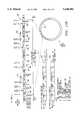
- FIG. 17Ais a block diagram of a preferred transmitter.
- a spread spectrum transmitter 1337operates in a cellular environment like that described with respect to FIG. 2.
- the transmitter 1337may be associated with either a base station or a user station in such a cellular environment.
- the transmitter 1337operates according to an over-air protocol for communication between the base station and the user station, in which transmission is time-division duplex between the base station and the user station in a single frame, and is time-division multiplexed among multiple user stations in a repeated pattern of frames.
- an over-air protocolfor communication between the base station and the user station, in which transmission is time-division duplex between the base station and the user station in a single frame, and is time-division multiplexed among multiple user stations in a repeated pattern of frames.
- Other and further details regarding a preferred over-air communication protocolmay be found in application Ser. Nos. 08/161,187, 08/215,306, and 08/284,053 cited above.
- the present inventionwill work in a variety of different communication environments,
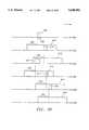
- a polling loop 1301(“major frame”) comprises a plurality of time slots 1302 ("minor frames”).
- Each minor frame 1302preferably comprises communication between a base station cellular station) and a user station (e.g., mobile user) in time division duplex--that is, the base station transmits to a user station and the user station transmits back to the base station within the same minor frame 1302.
- a minor frame 1302preferably comprises a power control pulse transmission 1304 from the user station to the base station, a base station transmission 1305, and a user station transmission 1306, each of which is surrounded by guard bands 1303. Details regarding the power control pulse transmission 1304 may be found in application Ser. No. 08/284,053, filed Aug. 1, 1994, and incorporated herein by reference.
- the base station transmission 1305 and the user station transmission 1306have a similar structure; thus, the following description regarding the base station transmission 1305 applies equally to the user station transmission 1306.
- the base station transmission 1305comprises an interframe gap 1351, a matched filter code 1352, a first fill code 1353, a data sequence 1354, and a second fill code 1355 similar to the first fill code 1353.
- the interframe gap 1351may be four chips in duration; the matched filter code 1352 may be 48 chips duration; the first fill code 1353 may be 16 chips in duration; the data sequence 1354 may be comprised of one or more symbol codes, each of which may be 32 chips, 128 chips, 2048 chips, or some other number of chips in duration depending upon a data rate for transmission between the base station and the user station; and the second fill code 1355 may be a sufficient number of chips in duration to complete the minor frame 1302.
- a plurality of minor frames 1302may comprise a channel.
- the fill codes 1353, 1355each comprise a code that has a low cross-correlation with each of the symbol codes, and may form a repeated pattern such as "0 1 0 1 . . . " or "0 0 1 1 . . . ".
- the interframe gap 1351may have the same code as one or both of the fill codes 1353, 1355.
- the fill codes 1353, 1355are generated primarily for the purpose of starting the modulator in a known state at the beginning of a transmission, and to avoid having to turn the transmitter off and on for the time period while the fill code 1305 is transmitted. Further, the fill codes 1353, 1355 may be selected to improve the spectral characteristics of the overall transmission. P The transmitter 1337 of FIG.
- a serial data stream 1321 of information to be transmittedis provided to the transmitter 1337 and converted to parallel data by a serial-to-parallel shift register 1322.
- the parallel data output by the serial-to-parallel shift register 1322is used to select from among a plurality of symbol codes stored in a symbol code table 1323.
- Each symbol codeas mentioned, is preferably 32 chips in length and represents a predetermined number of data bits (preferably to-parallel 5 data bits) from the serial data stream 1321.
- the transmitterIn addition to storing various symbol codes in the symbol code table 1323, the transmitter also comprises a matched filter code generator 1324 capable of generating a matched filter code 1352, and a fill code generator 1325 (which may be a table) capable of generating fill codes 1353, 1355.
- the symbol code table 1323, matched filter code generator 1324, and fill code generator 1325are selectively accessed by a control circuit 1320 for constructing a transmission such as a base station transmission 1305 or user station transmission 1306.
- a transmissionmay be constructed, for example, by concatenating or appending consecutive symbol codes, fill codes, and other code sequences as necessary to generate the appropriate chip sequence.
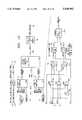
- the control circuit 1320has control outputs 1339 connected to various parts of the circuit for the purpose of exercising synchronous control.
- timing informationis generated with a clock circuit 1307 such as a crystal oscillator.
- the clock circuit 1307produces a 20 megahertz (MHz) clock signal and is coupled to an input of a clock chain 1308.
- the clock chain 1308generates a plurality of output clock signals in a manner known in the art.
- the clock chain 1308has as outputs a 20 MHz clock signal 1309, a 10 MHz clock signal 1310, a 5 MHz clock signal 1311, and a 2.5 MHz clock signal 1312.
- the 5 MHz clock signal 1311is coupled to a loop counter 1313, which, among other things, counts chips over the course of each minor frame 1302.
- the loop counter 1313produces a chip count signal 1314, a symbol count signal 1315, and a channel count signal 1316.
- the channel or loop count signal 1316indicates which minor frame 1302 is active within the polling loop 1301. Thus, if there are 32 minor frames 1302 in a polling loop 1301, the channel count signal 1316 counts from 0 to 31 and then resets.
- the control circuit 1320may issue commands to transmit information at the appropriate time.
- the symbol count signal 1315keeps track of how many symbols have been transmitted by the transmitter 1337 in the data sequence 1354. Thus, if the transmitter is to transmit 16 consecutive symbols as part of the data sequence 1354, then the symbol count signal 1315 counts from 0 to 15 and then resets.
- the chip count signal 1314keeps track of how many chips have been transmitted by the transmitter 1337 for the current symbol in the data sequence 1354. Thus, if each symbol code is 32 chips in length, the chip count signal 1314 counts from 0 to 31 and then resets. The chip count signal 1314 also provides timing information for those circuits in the transmitter which are clocked at each chip time Tc.
- the chip count signal 1314, the symbol count signal 1315, and the channel count signal 1316are coupled to a state decoder 1317, which determines whether the current chip is part of the matched filter code 1352, the fill code 1305, or a data sequence symbol code 1306, and which generates a selection signal 1318 and a set of control signals 1319.
- the control signals 1319are coupled to a control circuit 1320.
- a serial data stream 1321 of data to be transmittedis coupled to a serial-to-parallel shift register 1322, which converts the serial data stream 1321 to a sequence of 5-bit parallel symbols.
- the sequence of symbolsis coupled to an input of a symbol code table 1323, which selects for each symbol a specific symbol code unique to the symbol.
- the chip count signal 1314is coupled to the symbol code table 1323, the matched filter code generator 1324, and the fill code generator 1325. Outputs of the symbol code table 1323, the matched filter code generator 1324, and the fill code generator 1325 are coupled to inputs of a 3-1 multiplexer 1326. A control input of the 3-1 multiplexer 1326 is coupled to the selection signal 1318 from the control circuit 1320. The 3-1 multiplexer 1326 thus generates an output chip stream 1327 in accordance with the commands provided by the control circuit 1320.
- control circuit 1320may select a fill code to fill the interframe gap 1351 from the fill code generator 1325, a matched filter code 1352 from the matched filter code generator 1324, a first fill code 1353 from the fill code generator 1325, one or more symbol codes (depending on the amount of data to be transmitted and the data rate) corresponding to the data sequence 1354 from the symbol code table 1323, and a second fill code 1355 from the fill code generator 1325, in order to construct a transmission such as a base station transmission 1305 or a user station transmission 1306.
- the output chip stream 1327is coupled to a demultiplexer 1328, which separates its input chip stream into an I chip stream 1329 and a Q chip stream 1330, under control of the 2.5 MHz clock signal 1312 (i.e., the demultiplexer 1328 is clocked at half the chip rate Rc).
- the I chip stream 1329 and the Q chip stream 1330are connected to a waveform generator 1338 which generally constructs appropriate output waveforms based on the contents of the I chip stream 1329 and the Q chip stream 1330.
- the waveform generator 1338comprises an I lookup table 1332 and a Q lookup table 1334, each of which comprises memory such as ROM.
- the I lookup table 1332 and the Q lookup table 1334each contain fifteen digitized values for amplitude outputs of the P(t) devices 305 (for I) and 306 (for Q) shown in FIG. 6.
- the shape of the output waveformsmay be suitably altered, allowing transmission of MSK, SQAM, GMSK, SQORC, or other similar format as desired.
- the I lookup table 1332receives as its inputs both the present I chip from the I chip stream 1329 and the previous I chip from the I chip stream 1329 as stored in an I delay element 1331 (e.g., a latch). By having available the immediate past I chip and the present I chip, the transmitter knows what type of transition is occurring in the I chip stream 1329--that is, whether the I chip stream 1329 is undergoing a 0/0 transition, a 0/1 transition, a 1/0 transition, or a 1/1 transition. The type of transition determines the shape of the output waveform.
- an I delay element 1331e.g., a latch
- the I lookup table 1332provides as output eight sequential I waveform commands or "samples" per I chip time (i.e., 2Tc) which are connected to a digital-to-analog converter (DAC) for constructing a suitable waveform.
- the I lookup table 1332is provided a clock input of 20 MHz so that eight I waveform commands may be output per I chip time.
- the DAC for the I chip stream 1329comprises a 4-15 decoder 1335 which selects one of 15 possible output lines, coupled to a resistor ladder (not shown) and a low pass filter (not shown). Of course, other types of DAC's would be suitable for this purpose.
- Table 17-1 belowshows an example of how the 15 outputs of the 4-15 decoder 1335 relate to specific voltages to be output by the DAC to create a SQAM waveform varying between 1.5 V and 3.5 V:
- Table 17-2shows a sequence of eight selected values according to Table 17-1 for constructing an appropriate waveform depending on what type of transition is occurring in the I chip stream:
- An output corresponding to the Q chip stream 1330is generated in a similar manner to that of the I chip stream 1329.
- the Q lookup table 1334receives as its inputs both the present Q chip from the Q chip stream 1330 and the previous Q chip from the Q chip stream 1330 as stored in a Q delay element 1333. Based on its inputs, the Q lookup table 1334 determines what type of transition is occurring in the Q chip stream 1330.
- An output of the Q lookup table 1334is coupled to a 4-15 decoder 1336, which selects one of 15 output lines for sending a signal to a DAC configured in a similar manner to that described with respect to the I chip stream 1329.
- the contents of the I lookup table 1332 and the Q lookup table 1334are selected to generate an i(t) output waveform and a q(t) output waveform, respectively.
- An example of an output SQAM waveform 1370 according to the technique described above and the values set forth in Tables 17-1 and 17-2is shown in FIG. 17C.
- the waveform 1370comprises a 0/0 transition 1372, a 0/1 transition 1373, and a 1/1 transition 1374.
- Each transition 1372, 1373, 1374comprises eight discrete points 1371 corresponding to values selected by the 4-15 I lookup table 1332 (or Q lookup table 1334).
- the effect of the low pass filter (not shown) at the output of the waveform generator 1338smooths the shape of the waveform 1370 between discrete points 1371.
- Table 17-3shows an illustrative matched filter code 1352.
- the matched filter code generator 1324is configured to generate the code shown below in Table 17-3.
- matched filter code 1352for a particular application depends on the symbol codes (in a CSK system) or other chip codes being used; generally, the matched filter code 1352 is selected for low cross correlation with the other chip codes used in the particular communication environment.
- Table 17-4shows a presently preferred set of 32 symbol codes.
- the symbol code table 1323along with the appropriate commands from the control circuit 1320 are configured to generate a sequence of symbol codes selected from the set of 32 symbol codes shown in Table 17-4, in response to a sequence of 5-bit parallel symbols.
- FIGS. 18, 19, 21A and 21Bcollectively illustrate a preferred receiver.
- the illustrated receivergenerally operates by correlating to the matched filter code 1352 with a non-coherent parallel correlator (such as the two-register non-coherent CPM correlator 802 depicted in FIG. 12) to achieve synchronization for a plurality of serial correlators (such as the dual-integrator non-coherent serial CPM correlators 1102 depicted in FIG. 15), which serial CPM correlators are then used for correlating to a received data sequence 1354.
- a non-coherent parallel correlatorsuch as the two-register non-coherent CPM correlator 802 depicted in FIG. 12
- serial correlatorssuch as the dual-integrator non-coherent serial CPM correlators 1102 depicted in FIG. 15
- serial CPM correlatorsare then used for correlating to a received data sequence 1354.
- many alternate configurationsusing, for example, only parallel correlators, only serial correlators, or various combinations of
- FIGS. 21A and 21BA preferred embodiment of a receiver is shown in part in FIGS. 21A and 21B. Standard electrical engineering symbols and terms are used in FIGS. 21A and 21B; thus, the following explanation will be limited to relating FIGS. 21A and 21B to the prior description of the invention in some its various embodiments.
- a received signal 2001is provided to an IF amplifier shown in FIG. 21A.
- the received signal 2001may undergo prior conditioning and may be downconverted to an intermediate frequency for processing.
- the received signal 2001is coupled to a capacitor C4 which passes the high frequency components of the received signal 2001.
- the output of the capacitor C4is coupled to a first integrated chip U1 which is preferably an MC13155 chip manufactured by Motorola.
- the output of capacitor C4is coupled to a hardlimit amplifier 2003 located on the first integrated chip U1 for hardlimiting the output of capacitor C4.
- the hardlimit amplifierprovides a differential output comprising a first differential output signal 2010 and a second differential output signal 2011.
- the differential output signals 2010, 2011are coupled to a second integrated circuit U2 which, as shown in FIG. 21B, is preferably an RF2701 chip manufactured by RF Micro Devices. Specifically, the differential output signals 2010, 2011 are coupled to a differential amplifier 2033 which produces an amplified output signal 2030.
- the amplified output signal 2030is split into two branches by a power divider (not shown) and coupled via a first branch to a first multiplier 2031 (e.g., multiplier 1111 in FIG. 15) and via a second branch to a second multiplier 2032 (e.g., multiplier 1116 in FIG. 15).
- the first multiplier 2031has as a second input a reference signal 2036 comprising a first square wave of frequency ⁇ 1 t (which, after low pass filtering, becomes cos ⁇ 1 t), and the second multiplier 2032 has as another input a reference signal 2037 comprising a second square wave of frequency ⁇ 1 t (which, after low pass filtering, becomes sin ⁇ 1 t) phase offset from the first square wave by 90 degrees.
- the reference signals 2036, 2037are generated from a local oscillator (not shown) which provides a local oscillator signal 2025 to filter capacitor C39, the output of which is connected to the second integrated chip U2. Specifically, the output of capacitor C39 is connected to an amplifier 2038, the output of which is coupled to a quad divide-by-two circuit 2039 for splitting its input into two reference signals 2036, 2037, the first reference signal 2036 having a 0-degree delay and the second reference signal 2037 having a 90-degree delay.
- the outputs of multipliers 2031 and 2032are amplified by a first output amplifier 2034 and a second output amplifier 2035, respectively.
- the output of the first output amplifier 2034is coupled to a first low pass filter 2023, and the output of the second output amplifier 2035 is coupled to a second low pass filter 2024.
- the output of the first low pass filter 2023is connected to one input of a first comparator 2027.
- the output of the second low pass filter 2024is connected to one input of a second comparator 2040.
- the first comparator 2027 and second comparator 2040each have as a second input a DC threshold signal 2041 generated by a DC bias circuit 2022.
- the DC threshold signal 2041is coupled to the first comparator 2027 by a low pass filter comprising capacitor C52 and resistor R36, and similarly to the second comparator 2040 by a low pass filter comprising capacitor C53 and resistor R37.
- the first comparator 2027 and second comparator 2040provide output signals 2028 and 2029, respectively, each of which comprises a TTL level signal suitable for further processing using digital circuits.
- output signals 2028 and 2029may each comprise a square wave signal having values of +1 and 0 times a fixed voltage.
- the output signals 2028 and 2029are sampled and provided to remaining circuitry as shown in FIGS. 18 and 19. Specifically, the output signals 2028 and 2029 are sampled twice per chip time (i.e., at 10 MHz) as provided to the circuitry in FIG. 18, and once per chip time (i.e., at 5 MHz) as provided to the circuitry in FIG. 19.
- FIG. 18is a block diagram of a preferred non-coherent matched filter and associated receiver components.
- s*(t) 401are input to the circuitry of FIG. 18.
- a real I/imaginary Q signal 1401is connected to signal 2028 shown in FIG. 21B, and input to an even/odd shift register 1402.
- An imaginary I/real Q signal 1451is connected to signal 2029 shown in FIG. 21B, and input to an even/odd shift register 1452.
- the even/odd shift register 1402is 96 bits long. Because the real I/imaginary Q signal 1401 is clocked at twice the system clock rate, every other odd chip (rather than every odd chip) of the even/odd shift register 1402 is selected and compared with the odd chips of the matched filter code 1403. In a preferred embodiment, matches between every other odd chip of the even/odd shift register 1402 and the odd chips of the matched filter code are compared. The chip matches are coupled to real adder 1404 for counting. Every other even chip (rather than every even chip) of the even/odd shift register 1402 is compared with the even chips of the matched filter code 1403, and the result of the comparison coupled to the imaginary adder 1405 for counting.
- the even/odd shift register 1452is 96 bits long. Every other odd chip of the even/odd shift register 1452 is compared with the odd chips of the matched filter code 1403. Matches between every other odd chip of the even/odd shift register 1452 and the odd chips of the matched filter code are compared. The chip matches are coupled to the real adder 1404 for counting. Every other even chip of the even/odd shift register 1452 is compared with the even chips of the matched filter code 1403, and coupled to the imaginary adder 1405 for counting.
- the real adder 1404has 24 individual bit inputs, each one of which may be a logical "0" to indicate no match or a logical "1" to indicate a match.
- the real adder 1404generates a 5-bit real sum 1406, which represents the absolute value of the number of odd chips that were matched.
- the imaginary adder 1405has 24 individual bit inputs and generates a 5-bit imaginary sum 1407 representing the absolute value of the number of even chips that were matched.
- the real sum 1406 and the imaginary sum 1407are coupled to a Robertson device 1408, which computes an approximation of a square root of the sum of the squares of the real sum 1406 and the imaginary sum 1407, as described herein.
- An output of the Robertson device 1408is coupled to an input of a comparator 1409, which compares the output of the Robertson device 1408 with a threshold value 1410.
- the threshold valueis preset, or may be set in response to a control on the receiver.
- the threshold valuemay also be set in a variety of other manners, such as in response to a control in the transmission or to receiving conditions.
- a comparator 1409generates an output pulse 1411.
- the output pulseis a logical "1" when the input 1430 exceeds the threshold 1410, and a logical "0" when it does not.
- the output pulse 1411may have a duration of 100, 200, 300 or 400 nanoseconds.
- the output pulse 1411is coupled to an input of a center seeking detector circuit 1412.
- the center seeking detector circuit 1412receives the output pulse 1411 and generates a set clock pulse 1413 which denotes the end of the received matched filter code 1352, and which is aligned with the center of a received chip so that the receiver clock can be synchronized with the center of each received chip in a received chip stream.
- the center seeking detector circuit 1412counts the number of logic "1" values in the output pulse 1411 (i.e., the length of time that the output of the Robertson device 1408 exceeds the threshold value 1410), thereby measuring the duration of the output pulse 1411 (e.g., from 1 to 4 clock periods of the 10 MHz clock, corresponding to up to four bits of the even/odd shift register 1402 and the even/odd shift register 1452).
- the center seeking detector circuit 1412generates a set clock pulse 1413 which re-initializes a system clock for serial correlation by a set of serial correlators (see FIG. 19) after a preset delay period.
- the preset delay periodensures that the serial correlation clock is properly synchronized with the center of the output pulse 1411.
- Preferred delay periodsare shown in Table 18-1:
- the system clockmay be re-initialized at the start of each minor frame 1302.
- the set clock pulse 1413is coupled to a clock chain 1415, which is also coupled to a locally generated 40 MHz clock signal 1416.
- the clock chain 1415generates a 20 MHz clock signal 1417, a 10 MHz clock signal 1418, and a 5 MHz clock signal 1419.
- the 5 MHz clock signal 1419is coupled to, among other things, a set of 32 serial correlators (see FIG. 19).
- the 5 MHz clock signal 1419is coupled to a loop counter 1420.
- the loop counter 1420counts the number of chips received and generates a chip count signal 1421, a symbol count signal 1422, and a channel or loop count signal 1423, similar to the chip count signal 1314, symbol count signal 1315, and channel count signal 1316, respectively, generated in the transmitter 1337.
- the chip count signal 1421, symbol count signal 1422, and channel count signal 1423are coupled to a state decoder 1424, which determines whether the received chip is part of the matched filter code 1352, the fill code 1305, or a data sequence symbol code 1306, similar to the state decoder 1317 in the transmitter 1337, and generates a state identifier 1425, similar to the selection signal 1318 generated in the transmitter 1337.
- the state identifier 1425is coupled to an input of the center seeking detector circuit 1412.
- the state decoder 1424generates a synchronization signal 1426, which is coupled to a set of 32 serial correlators (see FIG. 19).
- the state decoder 1424also generates a plurality of control signals 1427, which are coupled to a control circuit 1428.
- the control circuit 1428has control outputs 1429 connected to various parts of the circuit for the purpose of exercising synchronous control.
- the center seeking detector circuit 1412also generates a set state signal 1414 which may be used to place the loop counter 1420 in a known state, or to reset the individual count signals 1421, 1422 and 1423 associated with the loop counter 1420.
- FIG. 20is a diagram of a series of correlation pulses 2007, 2011, 2012, 2013 and 2014 corresponding to output pulse 1411 over a series of minor frames 1302.
- a first correlation pulse 2007is detected as shown in FIG. 18.
- the first correlation pulse 2007has a duration of three sample periods 2008.
- the center seeking circuit 1412generates a set clock pulse 1413 having a delay of 150 nanoseconds.
- the control circuit 1428determines, based in part on the count signals 1421 through 1423 of the loop counter 1420, the next minor frame 1302 in which the receiver is to be active. In many cases, a receiver receives in only one minor frame 1302 per major frame 1301 located in the same relative position chronologically from major frame 1301 to major frame 1301. Thus, in the next active minor frame 1302, the receiver opens a timing window 2010 during which the next output pulse 1411 is expected.
- the timing windowmay be, for example, 1.6 milliseconds in duration, and will be opened a predetermined time length 2009 before the next output pulse 1411 is expected assuming no deviation between the transmitter and receiver clocks between transmissions.
- a second correlation pulse 2011is generated during the timing window 2010 but some amount of time after expected.
- the second correlation pulse 2011is two sample periods in duration, and thus, according to Table 18-1, the center seeking circuit 1412 generates a set clock pulse 1413 having a delay of 100 nanoseconds.
- the timing window 2010has been shifted in relative time based upon the second correlation pulse 2011, and a third correlation pulse 2012 is generated within the timing window 2010 but some amount of time before expected.
- the third correlation pulse 2012is four sample periods in duration and causes a set clock pulse 1413 having a delay of 200 nanoseconds.
- a fourth correlation pulse 2013 and fifth correlation pulse 2014are generated in the next two active minor frames 1302.
- no correlation pulseis generated; thus, the receiver remains inactive because synchronization has not been achieved. Measures may be undertaken at such a point to re acquire synchronization and/or re-establish proper timing.
- FIG. 19is a block diagram of a preferred system of serial correlators operating in parallel with one another and operating in conjunction with the circuitry of FIG. 18 and FIGS. 21A and 21B.
- a digitally sampled version of a real portion and an imaginary portion of the received signal s*(t) 401are input to the circuitry of FIG. 19.
- a real I/imaginary Q signal 1511 and an imaginary I/real Q signal 1512are generated from the received signal s*(t) 401.
- the 5 MHz clock signal 1419 and the synchronization signal 1426 as described in FIG. 18are coupled to a count chain 1501, which generates an output synchronization signal 1502 for the serial correlators and a counter clock 1503.
- the 5 MHz clock signal 1419, the synchronization signal 1502, the counter clock 1503, the real I/imaginary Q signal 1511 and the imaginary I/real Q signal 1512are each coupled to a set of 32 serial correlators 1504.
- a set of 32 symbol generators 1505, one for each symbol 00 through 1F (hexadecimal),are also coupled to each serial correlator 1504.
- Each serial correlator 1504recognizes a single one of the 32 symbol codes and generates a magnitude signal 1506 indicating the number of agreements with that symbol code.
- the 32 magnitude signals 1506are coupled to a best-of-M device 1507, which determines which one of the 32 magnitude signals 1506 has the greatest value and generates an output symbol 1508 based thereon. If serial output data is desired, the output symbol 1508 may be coupled to a parallel-to-serial shift register 1509, which generates a sequence of serial data bits 1510 in response.
- serial correlator 1504An exploded view of an individual serial correlator 1504 is also shown in FIG. 19.
- the serial correlator 1504 shown in the FIG. 19 embodimentoperates in a conceptually similar manner to the dual-integrator non-coherent serial CPM correlator 1102 depicted in FIG. 15.
- the real I/imaginary Q signal 1511is coupled to XNOR gates 1551 and 1552, and the imaginary I/real Q signal 1512 is coupled to XNOR gate 1552.
- XNOR gatesgenerate the inverted XOR of their inputs.
- the XNOR gates 1551 and 1552perform the function of multipliers 1121, 1123, 1125 and 1127 depicted in FIG. 15.
- Each serial correlator 1504is programmed to correlate to a different symbol code; accordingly, the appropriate symbol code is clocked into the XNOR gates 1551, 1552 and 1554 from the symbol generator 1505.
- the symbol codeis inverted by invertor 1553 before being received by XNOR gate 1554 because XNOR gate 1554 operates on the inverse of the q(t) signal.
- Summation and integrationis carried out by a pair of multiplexers 1555, 1556 and counters 1557, 1558.
- the outputs of the XNOR gates 1551 and 1552are coupled to an real multiplexer 1555; the outputs of the XNOR gates 1552 and 1554 are coupled to an imaginary multiplexer 1556.
- the counter clock 1503is coupled to a control input of the real multiplexer 1555 and the imaginary multiplexer 1556 in order to control the integrate-and-dump function.
- the outputs of the real multiplexer 1555 and the imaginary multiplexer 1556are coupled to the enable inputs of the real counter 1557 and the imaginary counter 1558, respectively.
- the real multiplexer 1555selects between real I and real Q signals and provides them to the real counter 1557 to effectively sum and integrate the real I and real Q signals; the imaginary multiplexer 1556 and imaginary counter 1558 operate in an analogous manner with respect to imaginary I and imaginary Q signals.
- a reset commandmay be provided to the real counter 1557 and the imaginary counter 1558 to perform an operation analogous to a "dump" as would be carried out with integrate-and-dump circuits shown in FIG. 15.
- the output of the real counter 1557 and of the imaginary counter 1558are coupled to a Robertson device 1559, which computes an approximation to the root of the sum of the squares of its inputs.
- An output of the Robertson device 1559is output from the serial correlator 1504, and generally corresponds to the final correlation signal 1144 such as described with respect to FIG. 15.
- a serial correlator 1504may be designed to operate with multi-bit resolution to improve correlation accuracy.
- FIG. 22is a block diagram showing a preferred embodiment of a Robertson device 1601.
- the Robertson device 1601has an input 1602 and an input 1603, and computes an approximation of the square root of the sum of the squares of its inputs, as shown in equation 1152.
- the input 1602 and input 1603may be binary inputs such as 5-bit binary numbers.
- the input 1602 and the input 1603are coupled to a comparator 1604, which generates a control output 1605 indicating whether the input 1602 is greater than the input 1603.
- the input 1602 and the input 1603are also coupled to a selector 1606, which outputs the greater of the input 1602 and the input 1603 in response to the control output 1605.
- the input 1602 and the input 1603are also coupled to a selector 1607, which outputs the lesser of the input 1602 and the input 1603 in response to an inverse of the control output 1605.
- the output of the selector 1606 and the output of the selector 1607are coupled to an adder 1608.
- the output of the second selector 1607is shifted right one bit, i.e., the 0 (least significant) bit of the output of the second selector 1607 may be discarded, the 1 (next least significant) bit of the output of the second selector 1607 may be transferred to the 0 (least significant) bit position, the 2 bit of the output of the second selector 1607 may be transferred to the 1 bit position, and so on.
- the right shifthas the effect of dividing the output of the second selector 1607 by two (and dropping the least significant bit).
- the output of the adder 1608may be output from the Robertson device 1601, which therefore effectuates equation 1152 as set forth herein.
- circuitry constituting either FIG. 17, or FIGS. 18, 19, and 21A-B, or all said figuresmay be incorporated onto a single integrated chip, along with supporting circuitry as necessary.
- datainformation to be transmitted from transmitter to receiver is referred to herein as "data”.
- datacomprises data, error-correcting codes, control information, protocol information, or other signals, and that all these are within the scope and spirit of the invention.
Landscapes
- Engineering & Computer Science (AREA)
- Computer Networks & Wireless Communication (AREA)
- Signal Processing (AREA)
- Digital Transmission Methods That Use Modulated Carrier Waves (AREA)
Abstract
Description
θ(t)=-Tan.sup.- [q(t)/i(t)]
i(t)=C.sub.odd (t) cos θ(t) (203)
q(t)=C.sub.even (t) sin θ(t) (204)
cos ω.sub.1 t=cos (ω.sub.0 +Δω)t+θ(603)
Real*(t)=Re {Au(t) exp (-jω.sub.0 t)}Re{Au(t) exp (-jω.sub.0 t)} cos ω.sub.1 (t)cos ω.sub.1 t=cos (ω.sub.0 t+θ)
y(t)=(A/2) i(t)
z(t)=(A/2) q(t)
Corr (t=16Tc)={(6.928+6.928).sup.2 +(-4+-4).sup.2 }.sup.1/2 =16y(t)=i(t)(0.707)-q(t)(0.707)
z(t)=-i(t)(0.707)+q(t)(0.707)
Corr (t=16Tc)={(2×5.657).sup.2 +(2×-5.657).sup.2 }.sup.1/2 =16______________________________________ θ R.sub.i + R.sub.q I.sub.i + I.sub.q Corr= ______________________________________ 0° 16 0.0 16.0 30 13.856 -8.0 16.0 45 11.314 -11.314 16.0 60 8.0 -13.856 16.0 90 0.0 -16.0 16.0 120 -8.0 -13.856 16.0 135 -11.314 -11.314 16.0 150 -13.856 -8.0 16.0 180 -16.0 0.0 16.0 210 -13.856 8.0 16.0 225 -11.314 11.314 16.0 240 -8.0 13.856 16.0 270 0.0 16.0 16.0 300 8.0 13.856 16.0 315 11.314 11.314 16.0 330 13.856 8.0 16.0 ______________________________________
Real*(t) correlation=16 cos θ
Imag*(t) correlation=-16 sin θ
Corr={(16 cos θ).sup.2 +(-16 sin θ).sup.2 }.sup.1/2 =16______________________________________ A B Inverted XOR (A,B) ______________________________________ -1 -1 +1 -1 +1 -1 +1 -1 -1 +1 +1 +1 ______________________________________
∥<x, y>∥=maximum (x,y)+(0.5) minimum (x,y)(1152)
TABLE 17-1 ______________________________________ Decoder (Hex) Output Amplitude (V) ______________________________________ 0 1.5 1 1.5674 2 1.700 3 1.8414 4 1.900 5 3.100 6 3.1586 7 3.300 8 3.4326 9 3.500 A 3.2071 B 2.8827 C 2.500 D 2.1173 E 1.7929 ______________________________________
TABLE 17-2 ______________________________________ Transition Decoder Output Sequence ______________________________________ 0 → 0 0, 1, 2, 3, 4, 3, 2, 1 0 → 1 0, 1, E, D, C, B, A, 8 1 → 0 9, 8, A, B, C, D, E, 1 1 → 1 9, 8, 7, 6, 5, 6, 7, 8 ______________________________________
TABLE 17-3 ______________________________________ Hexadecimal Value Binary value ______________________________________ 40 01000000 3E 00111110 34 00110100 B3 10110011 1A 00011010 A6 10100110 ______________________________________
TABLE 17-4 ______________________________________ Symbol Symbol Code (Hex) Symbol Symbol Code (Hex) ______________________________________ 000544D65E 10 0E4424A1 015B118EOB 11 5B1171F4 023D77E66D 12 3D771792 036822BD36 13 682242C7 04014BD451 14 014B2BAE 05541E8104 15541E7EFB 063278E762 163278189D 07672DB237 17 672D4DC8 08 0EBBDBA1 18 0EBB245E 095BEE8EF4 19 5BEE710B 0A 3D88E892 1A 3D86176D 0B 68DDBDC7 1B 68DD4238 0C 01B4D4AE 1C 01B42B51 0D 54E181FB 1D 54E17ED4 0E 3287E79D 1E 32671862 0F 67D2B2C8 1F 67D24D37 ______________________________________
TABLE 18-1 ______________________________________ Length of Output Pulse Delay in Nanoseconds ______________________________________ 1 50 2 100 3 150 4 200 ______________________________________
Claims (26)
Priority Applications (41)
| Application Number | Priority Date | Filing Date | Title |
|---|---|---|---|
| US08/304,091US5648982A (en) | 1994-09-09 | 1994-09-09 | Spread spectrum transmitter |
| US08/480,167US5629956A (en) | 1994-09-09 | 1995-06-07 | Method and apparatus for reception and noncoherent serial correlation of a continuous phase modulated signal |
| US08/477,480US5692007A (en) | 1994-09-09 | 1995-06-07 | Method and apparatus for differential phase encoding and decoding in spread-spectrum communication systems with continuous-phase modulation |
| US08/480,443US5754584A (en) | 1994-09-09 | 1995-06-07 | Non-coherent spread-spectrum continuous-phase modulation communication system |
| US08/481,613US5659574A (en) | 1994-09-09 | 1995-06-07 | Multi-bit correlation of continuous phase modulated signals |
| US08/480,442US5627856A (en) | 1994-09-09 | 1995-06-07 | Method and apparatus for receiving and despreading a continuous phase-modulated spread spectrum signal using self-synchronizing correlators |
| US08/486,824US5963586A (en) | 1994-09-09 | 1995-06-07 | Method and apparatus for parallel noncoherent correlation of a spread spectrum signal |
| US08/480,914US5832028A (en) | 1994-09-09 | 1995-06-07 | Method and apparatus for coherent serial correlation of a spread spectrum signal |
| US08/480,668US5610940A (en) | 1994-09-09 | 1995-06-07 | Method and apparatus for noncoherent reception and correlation of a continous phase modulated signal |
| US08/485,638US5680414A (en) | 1994-09-09 | 1995-06-07 | Synchronization apparatus and method for spread spectrum receiver |
| US08/486,883US5754585A (en) | 1994-09-09 | 1995-06-07 | Method and apparatus for serial noncoherent correlation of a spread spectrum signal |
| US08/484,007US5757847A (en) | 1994-09-09 | 1995-06-07 | Method and apparatus for decoding a phase encoded signal |
| AT03027042TATE451755T1 (en) | 1994-09-09 | 1995-08-25 | DESPREADING A CPM (CONTINUOUS PHASE MODULATION) SPREAD SPECTRUM SIGNAL |
| EP95932334AEP0806079B1 (en) | 1994-09-09 | 1995-08-25 | Transmission and reception of cpm spread-spectrum communications |
| EP03007108AEP1333589B1 (en) | 1994-09-09 | 1995-08-25 | Reception of CPM spread spectrum communications |
| DE69532209TDE69532209T2 (en) | 1994-09-09 | 1995-08-25 | TRANSMISSION AND RECEPTION OF CONTINUOUS, PHASE-MODULATED SPREADBAND SIGNALS |
| EP03018224AEP1376890B1 (en) | 1994-09-09 | 1995-08-25 | Wireless spread spectrum communication with preamble sounding gap |
| AT95932334TATE255295T1 (en) | 1994-09-09 | 1995-08-25 | TRANSMISSION AND RECEPTION OF CONTINUOUS, PHASE MODULATED SPREAD BAND SIGNALS |
| AT03007108TATE430409T1 (en) | 1994-09-09 | 1995-08-25 | RECEIVING CPM SPREAD SPECTRUM MESSAGE TRANSMISSIONS |
| KR1019970701540AKR970705865A (en) | 1994-09-09 | 1995-08-25 | Transmission and Reception of CPM Spread-Spectrum Communications (CPM) |
| DE69536027TDE69536027D1 (en) | 1994-09-09 | 1995-08-25 | Despreading a CPM (continuous phase modulation) spread spectrum signal |
| EP03018544AEP1376970A3 (en) | 1994-09-09 | 1995-08-25 | Wireless Spread Spectrum Communication with Centre Seeking Decorrelation |
| DE69535990TDE69535990D1 (en) | 1994-09-09 | 1995-08-25 | Wireless spread spectrum communication with preamble probing gap |
| AT03018224TATE438960T1 (en) | 1994-09-09 | 1995-08-25 | WIRELESS SPREAD SPECTRUM COMMUNICATION WITH PREAMBLE PROBING GAP |
| EP03027042AEP1420520B1 (en) | 1994-09-09 | 1995-08-25 | Despreading of a CPM (continuous phase modulation) spread-spectrum signal |
| PCT/US1995/010886WO1996008077A1 (en) | 1994-09-09 | 1995-08-25 | Transmission and reception of cpm spread-spectrum communications |
| DE69535945TDE69535945D1 (en) | 1994-09-09 | 1995-08-25 | Receive CPM spread spectrum message transmissions |
| EP03007231AEP1335551A3 (en) | 1994-09-09 | 1995-08-25 | Reception of CPM spread-spectrum communications |
| EP03007109AEP1333590A3 (en) | 1994-09-09 | 1995-08-25 | Correlator for reception of CPM spread-spectrum communications |
| EP03007110AEP1333606A3 (en) | 1994-09-09 | 1995-08-25 | Transmission of CPM spread spectrum communications |
| EP03007241AEP1339173A3 (en) | 1994-09-09 | 1995-08-25 | Receiver for spread spectrum signals |
| CA002199525ACA2199525A1 (en) | 1994-09-09 | 1995-08-25 | Transmission and reception of cpm spread-spectrum communications |
| EP03007111AEP1335550A3 (en) | 1994-09-09 | 1995-08-25 | Differential phase encoding apparatus |
| JP50954396AJP3471360B2 (en) | 1994-09-09 | 1995-08-25 | Transmission and reception of CPM spread spectrum communication |
| IL11508395AIL115083A (en) | 1994-09-09 | 1995-08-28 | Method and apparatus for serial noncoherent correlation of a spread spectrum signal |
| US08/769,187US5856998A (en) | 1994-09-09 | 1996-12-18 | Method and apparatus for correlating a continuous phase modulated spread spectrum signal |
| US08/928,846US5953370A (en) | 1994-09-09 | 1997-09-12 | Apparatus for receiving and correlating a spread spectrum signal |
| US08/970,662US5881100A (en) | 1994-09-09 | 1997-11-14 | Method and apparatus for coherent correlation of a spread spectrum signal |
| US09/307,646US6317452B1 (en) | 1994-09-09 | 1999-05-07 | Method and apparatus for wireless spread spectrum communication with preamble sounding gap |
| IL13698900AIL136989A0 (en) | 1994-09-09 | 2000-06-26 | Spread spectrum transmitter and method for use thereof |
| JP2003189691AJP3730236B2 (en) | 1994-09-09 | 2003-07-01 | Differential phase encoding apparatus and method for CPM spread spectrum communication |
Applications Claiming Priority (1)
| Application Number | Priority Date | Filing Date | Title |
|---|---|---|---|
| US08/304,091US5648982A (en) | 1994-09-09 | 1994-09-09 | Spread spectrum transmitter |
Related Child Applications (14)
| Application Number | Title | Priority Date | Filing Date |
|---|---|---|---|
| US08/480,442Continuation-In-PartUS5627856A (en) | 1994-09-09 | 1995-06-07 | Method and apparatus for receiving and despreading a continuous phase-modulated spread spectrum signal using self-synchronizing correlators |
| US47646195AContinuation-In-Part | 1994-09-09 | 1995-06-07 | |
| US08/480,167Continuation-In-PartUS5629956A (en) | 1994-09-09 | 1995-06-07 | Method and apparatus for reception and noncoherent serial correlation of a continuous phase modulated signal |
| US08/481,613Continuation-In-PartUS5659574A (en) | 1994-09-09 | 1995-06-07 | Multi-bit correlation of continuous phase modulated signals |
| US08/485,638Continuation-In-PartUS5680414A (en) | 1994-09-09 | 1995-06-07 | Synchronization apparatus and method for spread spectrum receiver |
| US08/477,480Continuation-In-PartUS5692007A (en) | 1994-09-09 | 1995-06-07 | Method and apparatus for differential phase encoding and decoding in spread-spectrum communication systems with continuous-phase modulation |
| US08/486,824Continuation-In-PartUS5963586A (en) | 1994-09-09 | 1995-06-07 | Method and apparatus for parallel noncoherent correlation of a spread spectrum signal |
| US08/484,007Continuation-In-PartUS5757847A (en) | 1994-09-09 | 1995-06-07 | Method and apparatus for decoding a phase encoded signal |
| US08/480,668Continuation-In-PartUS5610940A (en) | 1994-09-09 | 1995-06-07 | Method and apparatus for noncoherent reception and correlation of a continous phase modulated signal |
| US48090395AContinuation-In-Part | 1994-09-09 | 1995-06-07 | |
| US08/486,883Continuation-In-PartUS5754585A (en) | 1994-09-09 | 1995-06-07 | Method and apparatus for serial noncoherent correlation of a spread spectrum signal |
| US08/480,443Continuation-In-PartUS5754584A (en) | 1994-09-09 | 1995-06-07 | Non-coherent spread-spectrum continuous-phase modulation communication system |
| US08/480,914Continuation-In-PartUS5832028A (en) | 1994-09-09 | 1995-06-07 | Method and apparatus for coherent serial correlation of a spread spectrum signal |
| US48682795AContinuation-In-Part | 1994-09-09 | 1995-06-07 |
Publications (1)
| Publication Number | Publication Date |
|---|---|
| US5648982Atrue US5648982A (en) | 1997-07-15 |
Family
ID=23175011
Family Applications (1)
| Application Number | Title | Priority Date | Filing Date |
|---|---|---|---|
| US08/304,091Expired - LifetimeUS5648982A (en) | 1994-09-09 | 1994-09-09 | Spread spectrum transmitter |
Country Status (2)
| Country | Link |
|---|---|
| US (1) | US5648982A (en) |
| IL (1) | IL136989A0 (en) |
Cited By (49)
| Publication number | Priority date | Publication date | Assignee | Title |
|---|---|---|---|---|
| US5778027A (en)* | 1995-11-24 | 1998-07-07 | Telefonaktiebolaget Lm Ericsson | Method and apparatus for determining signal components using digital signal processing |
| US5818869A (en)* | 1994-08-22 | 1998-10-06 | Matsushita Electric Industrial Co., Ltd. | Spread spectrum communication synchronizing method and its circuit |
| US5862133A (en)* | 1996-08-02 | 1999-01-19 | Golden Bridge Technology | Packet-switched spread-spectrum system |
| US5864550A (en)* | 1995-05-05 | 1999-01-26 | Nokia Mobile Phones Ltd. | Wireless local area network system and receiver for the same |
| US6023052A (en)* | 1997-11-07 | 2000-02-08 | Shell Oil Company | Heater control |
| US6031865A (en)* | 1997-08-04 | 2000-02-29 | Motorola, Inc. | Rapidly decorrelating spreading sequences for DS-CDMA transceivers |
| RU2149508C1 (en)* | 1998-09-16 | 2000-05-20 | Сибирский государственный университет телекоммуникаций и информатики | Method for transmitting multiple-frequency parallel composite signal |
| US6079007A (en)* | 1998-03-10 | 2000-06-20 | Pan Atlantic Corporation | System and method for generating pseudo-random codes |
| US6237075B1 (en)* | 1998-03-10 | 2001-05-22 | Pan Atlantic Corporation | System and method for generating pseudo-random codes |
| US6317452B1 (en) | 1994-09-09 | 2001-11-13 | Xircom, Inc. | Method and apparatus for wireless spread spectrum communication with preamble sounding gap |
| US6324209B1 (en) | 2000-02-28 | 2001-11-27 | Golden Bridge Technology Inc. | Multi-channel spread spectrum system |
| US6363131B1 (en)* | 1998-04-29 | 2002-03-26 | Hughes Electronics Corporation | Method and apparatus for joint timing synchronization and frequency offset estimation |
| EP1053600A4 (en)* | 1998-01-05 | 2002-08-14 | Intel Corp | A method for using encoded spreading codes to achieve high bit densities in a direct-sequence |
| US6445749B2 (en)* | 1995-01-09 | 2002-09-03 | Intel Corporation | FMOD transceivers including continuous and burst operated TDMA, FDMA, spread spectrum CDMA, WCDMA, and CSMA |
| US20020144294A1 (en)* | 2001-02-02 | 2002-10-03 | Matthew Rabinowitz | Position location using terrestrial digital video broadcast television signals |
| US20020184653A1 (en)* | 2001-02-02 | 2002-12-05 | Pierce Matthew D. | Services based on position location using broadcast digital television signals |
| US20020199196A1 (en)* | 2001-06-21 | 2002-12-26 | Matthew Rabinowitz | Position location using global positioning signals augmented by broadcast television signals |
| US20030058504A1 (en)* | 2000-09-26 | 2003-03-27 | Cho Pak Shing | Method and system for mitigating nonlinear transmission impairments in fiber-optic communications systems |
| US6639990B1 (en) | 1998-12-03 | 2003-10-28 | Arthur W. Astrin | Low power full duplex wireless link |
| US20030231133A1 (en)* | 2001-02-02 | 2003-12-18 | Matthew Robinowitz | Position location using broadcast analog television signals |
| US20050015162A1 (en)* | 2001-08-17 | 2005-01-20 | Omura Jimmy K. | Position location using digital audio broadcast signals |
| US20050030229A1 (en)* | 2001-02-02 | 2005-02-10 | Spilker James J. | Position location and data transmission using pseudo digital television transmitters |
| US20050066373A1 (en)* | 2001-02-02 | 2005-03-24 | Matthew Rabinowitz | Position location using broadcast digital television signals |
| US20050163084A1 (en)* | 1996-09-03 | 2005-07-28 | Golden Bridge Technology, Inc. | Packet spread-spectrum transmitter |
| US20050176386A1 (en)* | 2004-02-10 | 2005-08-11 | Brodhead Colin D. | System and method for transmitting data via wave reflection |
| WO2004077813A3 (en)* | 2003-02-24 | 2005-11-03 | Rosum Corp | Location and data transmission using television transmitters |
| US20050251844A1 (en)* | 2001-02-02 | 2005-11-10 | Massimiliano Martone | Blind correlation for high precision ranging of coded OFDM signals |
| US20070050824A1 (en)* | 2001-02-02 | 2007-03-01 | Andy Lee | Location identification using broadcast wireless signal signatures |
| US20070182633A1 (en)* | 2001-02-02 | 2007-08-09 | Rosum Corporation | Monitor Units for Television Signals |
| US20070296632A1 (en)* | 2006-06-22 | 2007-12-27 | Guttorm Opshaug | Psuedo Television Transmitters for Position Location |
| US20080170645A1 (en)* | 2007-01-12 | 2008-07-17 | General Dynamics C4 Systems, Inc. | Methods and systems for acquiring signals using coherent match filtering |
| US7498873B2 (en) | 2005-11-02 | 2009-03-03 | Rosom Corporation | Wide-lane pseudorange measurements using FM signals |
| US20090070847A1 (en)* | 2007-07-06 | 2009-03-12 | Rosum Corporation | Positioning with Time Sliced Single Frequency Networks |
| US20090175379A1 (en)* | 2007-12-12 | 2009-07-09 | Rosum Corporation | Transmitter Identification For Wireless Signals Having A Digital Audio Broadcast Physical Layer |
| US7737893B1 (en) | 2006-06-28 | 2010-06-15 | Rosum Corporation | Positioning in a single-frequency network |
| US7792156B1 (en) | 2008-01-10 | 2010-09-07 | Rosum Corporation | ATSC transmitter identifier signaling |
| US7936642B1 (en)* | 2008-01-02 | 2011-05-03 | Atheros Communications, Inc. | High sensitivity GPS-assisted time source |
| US8106828B1 (en) | 2005-11-22 | 2012-01-31 | Trueposition, Inc. | Location identification using broadcast wireless signal signatures |
| US8125389B1 (en) | 2008-10-20 | 2012-02-28 | Trueposition, Inc. | Doppler-aided positioning, navigation, and timing using broadcast television signals |
| US8139680B2 (en) | 2007-01-12 | 2012-03-20 | General Dynamics C4 Systems, Inc. | Signal acquisition methods and apparatus in wireless communication systems |
| US8149168B1 (en) | 2006-01-17 | 2012-04-03 | Trueposition, Inc. | Position determination using wireless local area network signals and television signals |
| US8179318B1 (en) | 2005-09-28 | 2012-05-15 | Trueposition, Inc. | Precise position determination using VHF omni-directional radio range signals |
| US8233091B1 (en) | 2007-05-16 | 2012-07-31 | Trueposition, Inc. | Positioning and time transfer using television synchronization signals |
| US8253627B1 (en) | 2009-02-13 | 2012-08-28 | David Burgess | Position determination with NRSC-5 digital radio signals |
| US8677440B2 (en) | 2001-02-02 | 2014-03-18 | Trueposition, Inc. | Position determination using ATSC-M/H signals |
| US8682341B1 (en) | 2006-11-22 | 2014-03-25 | Trueposition, Inc. | Blind identification of single-frequency-network transmitters |
| US8754807B2 (en) | 2001-02-02 | 2014-06-17 | Trueposition, Inc. | Time, frequency, and location determination for femtocells |
| US9829910B2 (en)* | 2015-01-16 | 2017-11-28 | Brock Franklin Roberts | Harmonic arbitrary waveform generator |
| US10809366B2 (en)* | 2015-02-04 | 2020-10-20 | Artsys360 Ltd. | Multimodal radar system |
Citations (147)
| Publication number | Priority date | Publication date | Assignee | Title |
|---|---|---|---|---|
| US3358227A (en)* | 1964-05-26 | 1967-12-12 | John W Taylor | Analyzer system using phase distortion measurements |
| US3906489A (en)* | 1973-03-30 | 1975-09-16 | Siemens Ag | Digital-to-analog converter |
| US3934203A (en)* | 1974-05-24 | 1976-01-20 | The United States Of America As Represented By The Secretary Of The Navy | Spread spectrum modem |
| US4100498A (en)* | 1977-06-20 | 1978-07-11 | The United States Of America As Represented By The Secretary Of The Navy | Discrete chirp frequency synthesizer |
| US4163944A (en)* | 1976-12-22 | 1979-08-07 | Ncr Corporation | Compensation circuit for an electrical signal mixer |
| US4164628A (en)* | 1977-06-06 | 1979-08-14 | International Telephone And Telegraph Corporation | Processor for multiple, continuous, spread spectrum signals |
| US4189677A (en)* | 1978-03-13 | 1980-02-19 | Purdue Research Foundation | Demodulator unit for spread spectrum apparatus utilized in a cellular mobile communication system |
| US4217563A (en)* | 1975-12-22 | 1980-08-12 | Westinghouse Electric Corp. | Surface wave phase correlator and monopulse radar system employing the same |
| US4222115A (en)* | 1978-03-13 | 1980-09-09 | Purdue Research Foundation | Spread spectrum apparatus for cellular mobile communication systems |
| US4231005A (en)* | 1979-07-09 | 1980-10-28 | Westinghouse Electric Corp. | Constant false alarm rate radar system and method of operating the same |
| US4242641A (en)* | 1978-04-06 | 1980-12-30 | Le Materiel Telephonique | Methods and apparatus for demodulating a differentially phase-modulated signal |
| US4247942A (en)* | 1961-03-01 | 1981-01-27 | Ford Aerospace & Communications Corp. | Jam resistant communication system |
| US4285060A (en)* | 1978-02-28 | 1981-08-18 | Harris Corporation | Spread spectrum code tracking loop |
| US4291410A (en)* | 1979-10-24 | 1981-09-22 | Rockwell International Corporation | Multipath diversity spread spectrum receiver |
| US4301530A (en)* | 1978-12-18 | 1981-11-17 | The United States Of America As Represented By The Secretary Of The Army | Orthogonal spread spectrum time division multiple accessing mobile subscriber access system |
| US4324001A (en)* | 1980-08-15 | 1982-04-06 | Communications Satellite Corporation | Synchronizer for MSK burst communications |
| US4327438A (en)* | 1978-12-19 | 1982-04-27 | Siemens Aktiengesellschaft | Receiving circuit in an interference-suppressing communications system comprising narrow-band conventional message modulation and additional pseudo-noise phase shift keying |
| US4338579A (en)* | 1980-07-30 | 1982-07-06 | Communications Satelite Corp. | Frequency shift offset quadrature modulation and demodulation |
| US4339724A (en)* | 1979-05-10 | 1982-07-13 | Kamilo Feher | Filter |
| US4355411A (en)* | 1980-03-24 | 1982-10-19 | Bell Telephone Laboratories, Incorporated | Technique for efficient spectrum utilization in mobile radio systems using space diversity |
| US4355399A (en)* | 1981-02-23 | 1982-10-19 | Bell Telephone Laboratories, Incorporated | Adaptive spread spectrum FH-MFSK transmitter and receiver |
| US4392231A (en)* | 1980-06-30 | 1983-07-05 | Bell Telephone Laboratories, Incorporated | Spread spectrum FH-MFSK decoder |
| US4418425A (en)* | 1981-08-31 | 1983-11-29 | Ibm Corporation | Encryption using destination addresses in a TDMA satellite communications network |
| US4418393A (en)* | 1980-10-27 | 1983-11-29 | Sperry Corporation | Matched filter spread spectrum code recovery apparatus |
| US4455651A (en)* | 1980-10-20 | 1984-06-19 | Equatorial Communications Company | Satellite communications system and apparatus |
| US4481640A (en)* | 1982-06-30 | 1984-11-06 | Canadian Patents And Development Limited | Spread spectrum modem |
| US4506372A (en)* | 1981-11-11 | 1985-03-19 | Lgz Landis & Gyr Zug Ag. | Method and apparatus for recognizing in a receiver the start of a telegram signal consisting of a bit impulse sequence |
| US4517679A (en)* | 1982-03-10 | 1985-05-14 | Emi Limited | Communication over noisy lines |
| US4525835A (en)* | 1981-10-13 | 1985-06-25 | International Standard Electric Corporation | Duplex radio system utilizing time compression expansion |
| AU3984485A (en) | 1984-03-24 | 1985-09-26 | Standard Elektrik Lorenz Aktiengesellschaft | Tdm cellular radio communications |
| US4550414A (en)* | 1983-04-12 | 1985-10-29 | Charles Stark Draper Laboratory, Inc. | Spread spectrum adaptive code tracker |
| US4561089A (en)* | 1984-03-23 | 1985-12-24 | Sangamo Weston, Inc. | Correlation detectors for use in direct sequence spread spectrum signal receiver |
| US4567588A (en)* | 1984-03-23 | 1986-01-28 | Sangamo Weston, Inc. | Synchronization system for use in direct sequence spread spectrum signal receiver |
| US4567602A (en)* | 1983-06-13 | 1986-01-28 | Canadian Patents And Development Limited | Correlated signal processor |
| US4583048A (en)* | 1985-02-26 | 1986-04-15 | Rca Corporation | MSK digital demodulator for burst communications |
| US4587662A (en)* | 1983-01-28 | 1986-05-06 | International Standard Electric Corporation | TDMA spread-spectrum receiver with coherent detection |
| US4601047A (en)* | 1984-03-23 | 1986-07-15 | Sangamo Weston, Inc. | Code division multiplexer using direct sequence spread spectrum signal processing |
| US4606039A (en)* | 1983-07-21 | 1986-08-12 | Societe Nationale D'etudes Et De Construction De Moteurs D'aviation S.N.E.C.M.A. | Spread spectrum coding method and apparatus |
| US4612637A (en)* | 1983-08-01 | 1986-09-16 | U.S. Philips Corporation | Multiple-access communications system |
| US4616229A (en)* | 1983-09-30 | 1986-10-07 | Westinghouse Electric Corp. | System and method of compensating a doppler processor for input unbalance and an unbalance measuring sensor for use therein |
| US4621365A (en)* | 1984-11-16 | 1986-11-04 | Hughes Aircraft Company | Synchronization preamble correlation detector and frequency estimator |
| US4630283A (en)* | 1985-07-17 | 1986-12-16 | Rca Corporation | Fast acquisition burst mode spread spectrum communications system with pilot carrier |
| US4641317A (en)* | 1984-12-03 | 1987-02-03 | Charles A. Phillips | Spread spectrum radio transmission system |
| US4644565A (en)* | 1984-06-12 | 1987-02-17 | Canadian Patents And Development Limited-Societe Canadienne Des Brevets Et D'exploitation Limitee | Superposed quadrature modulated baseband signal processor |
| US4647863A (en)* | 1985-11-01 | 1987-03-03 | The United States Of America As Represented By The Secretary Of The Army | Saw transition detector for PSK signals |
| US4648099A (en)* | 1984-12-17 | 1987-03-03 | Allied Corporation | Digital minimum shift keyed modulator |
| US4649549A (en)* | 1983-08-30 | 1987-03-10 | Sophisticated Signals And Circuits | Apparatus for synchronizing linear PN sequences |
| US4653069A (en)* | 1975-11-06 | 1987-03-24 | General Electric Company | Spread spectrum correlation receiver |
| US4660164A (en)* | 1983-12-05 | 1987-04-21 | The United States Of America As Represented By The Secretary Of The Navy | Multiplexed digital correlator |
| US4672254A (en)* | 1985-10-11 | 1987-06-09 | Massachusetts Institute Of Technology | Surface acoustic wave devices and method of manufacture thereof |
| US4675863A (en)* | 1985-03-20 | 1987-06-23 | International Mobile Machines Corp. | Subscriber RF telephone system for providing multiple speech and/or data signals simultaneously over either a single or a plurality of RF channels |
| US4686668A (en)* | 1984-05-08 | 1987-08-11 | Nec Corporation | Loopback of a PCM signal with loopback command signal bits placed in each frame of the signal as predetermined ones of overhead bits |
| US4688210A (en)* | 1985-03-29 | 1987-08-18 | U.S. Philips Corporation | Method of and arrangement for synchronizing the receiver arrangements in a digital multiplex transmission system |
| US4691326A (en)* | 1984-04-17 | 1987-09-01 | Clarion Co., Ltd. | Spread-spectrum communication system |
| US4707839A (en)* | 1983-09-26 | 1987-11-17 | Harris Corporation | Spread spectrum correlator for recovering CCSK data from a PN spread MSK waveform |
| US4736371A (en)* | 1985-12-30 | 1988-04-05 | Nec Corporation | Satellite communications system with random multiple access and time slot reservation |
| US4742512A (en)* | 1985-07-19 | 1988-05-03 | Nec Corporation | Multipoint communication system having polling and reservation schemes |
| US4745628A (en)* | 1986-04-15 | 1988-05-17 | Terra Marine Engineering, Inc. | Symbol generator for phase modulated system |
| US4745378A (en)* | 1984-09-21 | 1988-05-17 | Clarion Co., Ltd. | Surface acoustic wave device |
| US4754453A (en)* | 1985-07-31 | 1988-06-28 | U.S. Philips Corporation | Digital radio transmission system with a connection-accompanying organization channel in the time-division multiplex frame |
| US4759034A (en)* | 1986-12-02 | 1988-07-19 | General Research Of Electronics, Inc. | Multi-step spread spectrum communication apparatus |
| US4774715A (en)* | 1987-03-11 | 1988-09-27 | Telesystems Slw Inc. | Device for demodulating a spread spectrum signal |
| US4804938A (en)* | 1986-10-24 | 1989-02-14 | Sangamo Weston, Inc. | Distribution energy management system |
| US4805208A (en)* | 1988-01-15 | 1989-02-14 | Niravoice, Inc. | Modem compression system for telephone network |
| US4807222A (en)* | 1986-08-25 | 1989-02-21 | American Telephone And Telegraph Company At&T Bell Laboratories | Cordless accessed high-speed high-capacity local area networks |
| US4811357A (en)* | 1988-01-04 | 1989-03-07 | Paradyne Corporation | Secondary channel for digital modems using spread spectrum subliminal induced modulation |
| US4815106A (en)* | 1986-04-16 | 1989-03-21 | Adaptive Networks, Inc. | Power line communication apparatus |
| US4837786A (en)* | 1986-08-07 | 1989-06-06 | Comstream Corporation | Technique for mitigating rain fading in a satellite communications system using quadrature phase shift keying |
| US4864589A (en)* | 1985-07-24 | 1989-09-05 | Nec Home Electronics Ltd. | Spread spectrum power line communications |
| US4894842A (en)* | 1987-10-15 | 1990-01-16 | The Charles Stark Draper Laboratory, Inc. | Precorrelation digital spread spectrum receiver |
| US4901307A (en)* | 1986-10-17 | 1990-02-13 | Qualcomm, Inc. | Spread spectrum multiple access communication system using satellite or terrestrial repeaters |
| US4918689A (en)* | 1985-10-10 | 1990-04-17 | Bell Communications Research, Inc. | Asynchronous communication system |
| US4979186A (en)* | 1984-12-03 | 1990-12-18 | Charles A. Phillips | Time domain radio transmission system |
| US4984247A (en)* | 1988-09-29 | 1991-01-08 | Ascom Zelcom Ag | Digital radio transmission system for a cellular network, using the spread spectrum method |
| US5001489A (en)* | 1988-11-02 | 1991-03-19 | Westinghouse Electric Corp. | Digital phase detector |
| US5005183A (en)* | 1985-02-04 | 1991-04-02 | Mitel Telecom Limited | Wireless telephone system |
| US5008953A (en)* | 1989-06-26 | 1991-04-16 | Telefonaktiebolaget L M Ericsson | Mobile station link supervision utilizing digital voice color codes |
| US5016255A (en)* | 1989-08-07 | 1991-05-14 | Omnipoint Data Company, Incorporated | Asymmetric spread spectrum correlator |
| US5022046A (en)* | 1989-04-14 | 1991-06-04 | The United States Of America As Represented By The Secretary Of The Air Force | Narrowband/wideband packet data communication system |
| US5022047A (en)* | 1989-08-07 | 1991-06-04 | Omnipoint Data Corporation | Spread spectrum correlator |
| US5023887A (en)* | 1989-03-02 | 1991-06-11 | Tokyo Keiki Company Ltd. | Data transmission system using spread spectrum communication |
| US5025452A (en)* | 1990-03-20 | 1991-06-18 | Andrew Corporation | Full-duplex, sub-band spread spectrum communications system |
| US5029184A (en)* | 1990-01-24 | 1991-07-02 | Harris Corporation | Low probability of intercept communication system |
| US5042050A (en)* | 1989-05-26 | 1991-08-20 | U.S. Philips Corporation | Digital cordless telephone systems |
| US5056109A (en)* | 1989-11-07 | 1991-10-08 | Qualcomm, Inc. | Method and apparatus for controlling transmission power in a cdma cellular mobile telephone system |
| US5066957A (en)* | 1989-04-21 | 1991-11-19 | Kokusai Denshin Denwa Co., Ltd. | Hybrid modulation satellite communication system |
| US5073900A (en)* | 1990-03-19 | 1991-12-17 | Mallinckrodt Albert J | Integrated cellular communications system |
| US5081642A (en)* | 1990-08-06 | 1992-01-14 | Omnipoint Data Company, Incorporated | Reciprocal saw correlator method and apparatus |
| US5093637A (en)* | 1987-12-27 | 1992-03-03 | Mitsubishi Denki Kabushiki Kaisha | Modulation device with input signal modification for correction of amplifier nonlinearities |
| US5101501A (en)* | 1989-11-07 | 1992-03-31 | Qualcomm Incorporated | Method and system for providing a soft handoff in communications in a cdma cellular telephone system |
| US5103459A (en)* | 1990-06-25 | 1992-04-07 | Qualcomm Incorporated | System and method for generating signal waveforms in a cdma cellular telephone system |
| US5107225A (en)* | 1990-11-30 | 1992-04-21 | Qualcomm Incorporated | High dynamic range closed loop automatic gain control circuit |
| US5109390A (en)* | 1989-11-07 | 1992-04-28 | Qualcomm Incorporated | Diversity receiver in a cdma cellular telephone system |
| GB2211053B (en) | 1987-10-09 | 1992-05-06 | Clarion Co Ltd | Spread spectrum communication receiver |
| US5132986A (en)* | 1989-12-22 | 1992-07-21 | Nec Home Electronics Ltd. | Csk communication system |
| US5146471A (en)* | 1989-03-23 | 1992-09-08 | Echelon Systems Corporation | Correlator for spread spectrum communications systems |
| US5150377A (en)* | 1990-11-02 | 1992-09-22 | At&T Bell Laboratories | Direct sequence spread spectrum (dsss) communications system with frequency modulation utilized to achieve spectral spreading |
| US5157686A (en) | 1990-05-24 | 1992-10-20 | Cylink Corporation | Method and apparatus for the modulation of spread spectrum radio signals |
| US5166952A (en) | 1990-05-24 | 1992-11-24 | Cylink Corporation | Method and apparatus for the reception and demodulation of spread spectrum radio signals |
| US5170412A (en) | 1990-11-22 | 1992-12-08 | Ascom Tech Ag. | Multiple access method |
| US5177765A (en) | 1991-06-03 | 1993-01-05 | Spectralink Corporation | Direct-sequence spread-spectrum digital signal acquisition and tracking system and method therefor |
| US5177766A (en) | 1991-06-03 | 1993-01-05 | Spectralink Corporation | Digital clock timing generation in a spread-spectrum digital communication system |
| US5179571A (en) | 1991-07-10 | 1993-01-12 | Scs Mobilecom, Inc. | Spread spectrum cellular handoff apparatus and method |
| US5181225A (en) | 1990-11-22 | 1993-01-19 | Ascom Tech. Ag. | Receiver for a dsss signal |
| US5185610A (en) | 1990-08-20 | 1993-02-09 | Texas Instruments Incorporated | GPS system and method for deriving pointing or attitude from a single GPS receiver |
| US5191597A (en) | 1990-01-22 | 1993-03-02 | Telefonaktiebolaget L M Ericsson | Method of compensating for non-linearities in an end amplifier incorporated in a radio transmitter |
| US5210771A (en) | 1991-08-01 | 1993-05-11 | Motorola, Inc. | Multiple user spread-spectrum communication system |
| US5216691A (en) | 1989-10-19 | 1993-06-01 | Ascom Zelcom Ag | Digital receiver for spread-spectrum signals |
| US5218618A (en) | 1990-11-07 | 1993-06-08 | Hughes Aircraft Company | Cellular telephone service using spread spectrum transmission |
| US5222099A (en) | 1991-01-21 | 1993-06-22 | Sony Corporation | Spread spectrum signal receiving apparatus |
| US5224120A (en) | 1990-12-05 | 1993-06-29 | Interdigital Technology Corporation | Dynamic capacity allocation CDMA spread spectrum communications |
| US5231646A (en) | 1992-03-16 | 1993-07-27 | Kyros Corporation | Communications system |
| US5243622A (en) | 1991-08-02 | 1993-09-07 | General Dynamics Corporation, Electronics Division | Direct-sequence spread-spectrum communication system with asynchronous despreading |
| US5253268A (en) | 1990-05-24 | 1993-10-12 | Cylink Corporation | Method and apparatus for the correlation of sample bits of spread spectrum radio signals |
| US5255288A (en) | 1990-01-31 | 1993-10-19 | Nec Corporation | Arrangement for converting binary input signal into corresponding in-phase and quadrature phase signals |
| US5257283A (en) | 1989-11-07 | 1993-10-26 | Qualcomm Incorporated | Spread spectrum transmitter power control method and system |
| US5263045A (en) | 1990-12-05 | 1993-11-16 | Interdigital Technology Corporation | Spread spectrum conference call system and method |
| US5263047A (en) | 1992-07-02 | 1993-11-16 | Motorola, Inc. | Multiple cavity tuning of a transmitter output in a communication system |
| US5265119A (en) | 1989-11-07 | 1993-11-23 | Qualcomm Incorporated | Method and apparatus for controlling transmission power in a CDMA cellular mobile telephone system |
| US5267262A (en) | 1989-11-07 | 1993-11-30 | Qualcomm Incorporated | Transmitter power control system |
| US5267261A (en) | 1992-03-05 | 1993-11-30 | Qualcomm Incorporated | Mobile station assisted soft handoff in a CDMA cellular communications system |
| US5276704A (en) | 1990-07-23 | 1994-01-04 | Omnipoint Data Company, Inc. | SAWC phase detection method and apparatus |
| US5276705A (en) | 1993-01-06 | 1994-01-04 | The Boeing Company | CCD demodulator/correlator |
| US5280537A (en) | 1991-11-26 | 1994-01-18 | Nippon Telegraph And Telephone Corporation | Digital communication system using superposed transmission of high speed and low speed digital signals |
| US5280472A (en) | 1990-12-07 | 1994-01-18 | Qualcomm Incorporated | CDMA microcellular telephone system and distributed antenna system therefor |
| US5289497A (en) | 1991-05-23 | 1994-02-22 | Interdigital Technology Corporation | Broadcast synchronized communication system |
| US5313457A (en) | 1992-04-14 | 1994-05-17 | Trimble Navigation Limited | Code position modulation system and method for multiple user satellite communications |
| US5319634A (en) | 1991-10-07 | 1994-06-07 | Phoenix Corporation | Multiple access telephone extension systems and methods |
| US5341396A (en) | 1993-03-02 | 1994-08-23 | The Boeing Company | Multi-rate spread system |
| US5347284A (en) | 1991-02-28 | 1994-09-13 | Texas Instruments Incorporated | System and method for a digital navigation satellite receiver |
| US5353303A (en) | 1993-10-04 | 1994-10-04 | The United States Of America As Represented By The Secretary Of The Air Force | Technique for increasing the data rate in a spread spectrum data link |
| US5353300A (en) | 1993-06-07 | 1994-10-04 | Motorola, Inc. | Communication method for an adaptive direct sequence CDMA communication system |
| US5383219A (en) | 1993-11-22 | 1995-01-17 | Qualcomm Incorporated | Fast forward link power control in a code division multiple access system |
| US5392287A (en) | 1992-03-05 | 1995-02-21 | Qualcomm Incorporated | Apparatus and method for reducing power consumption in a mobile communications receiver |
| US5400359A (en) | 1992-03-23 | 1995-03-21 | Sharp Kabushiki Kaisha | Spread spectrum communication system and an apparatus for communication utilizing this system |
| US5402413A (en) | 1991-04-08 | 1995-03-28 | Omnipoint Corporation | Three-cell wireless communication system |
| US5414796A (en) | 1991-06-11 | 1995-05-09 | Qualcomm Incorporated | Variable rate vocoder |
| US5414728A (en) | 1993-11-01 | 1995-05-09 | Qualcomm Incorporated | Method and apparatus for bifurcating signal transmission over in-phase and quadrature phase spread spectrum communication channels |
| US5442662A (en) | 1993-07-05 | 1995-08-15 | Oki Electric Industry Co., Ltd. | Code-division multiple-access communication system providing enhanced capacity within limited bandwidth |
| US5446727A (en) | 1993-11-30 | 1995-08-29 | Motorola Inc. | Method and apparatus for time aligning signals for reception in a code-division multiple access communication system |
| US5455822A (en) | 1990-10-23 | 1995-10-03 | Omnipoint Corporation | Method and apparatus for establishing spread spectrum communication |
| US5467367A (en) | 1991-06-07 | 1995-11-14 | Canon Kabushiki Kaisha | Spread spectrum communication apparatus and telephone exchange system |
| US5469469A (en) | 1993-12-07 | 1995-11-21 | University Of Massachusetts Lowell Research Foundation | Composite spread spectrum signal including modulator demodulator |
| US5471497A (en) | 1993-11-01 | 1995-11-28 | Zehavi; Ephraim | Method and apparatus for variable rate signal transmission in a spread spectrum communication system using coset coding |
| US5481533A (en) | 1994-05-12 | 1996-01-02 | Bell Communications Research, Inc. | Hybrid intra-cell TDMA/inter-cell CDMA for wireless networks |
| US5488629A (en) | 1993-02-17 | 1996-01-30 | Matsushita Electric Industrial Co., Ltd. | Signal processing circuit for spread spectrum communications |
| US5515378A (en) | 1991-12-12 | 1996-05-07 | Arraycomm, Inc. | Spatial division multiple access wireless communication systems |
- 1994
- 1994-09-09USUS08/304,091patent/US5648982A/ennot_activeExpired - Lifetime
- 2000
- 2000-06-26ILIL13698900Apatent/IL136989A0/enunknown
Patent Citations (157)
| Publication number | Priority date | Publication date | Assignee | Title |
|---|---|---|---|---|
| US4247942A (en)* | 1961-03-01 | 1981-01-27 | Ford Aerospace & Communications Corp. | Jam resistant communication system |
| US3358227A (en)* | 1964-05-26 | 1967-12-12 | John W Taylor | Analyzer system using phase distortion measurements |
| US3906489A (en)* | 1973-03-30 | 1975-09-16 | Siemens Ag | Digital-to-analog converter |
| US3934203A (en)* | 1974-05-24 | 1976-01-20 | The United States Of America As Represented By The Secretary Of The Navy | Spread spectrum modem |
| US4653069A (en)* | 1975-11-06 | 1987-03-24 | General Electric Company | Spread spectrum correlation receiver |
| US4217563A (en)* | 1975-12-22 | 1980-08-12 | Westinghouse Electric Corp. | Surface wave phase correlator and monopulse radar system employing the same |
| US4163944A (en)* | 1976-12-22 | 1979-08-07 | Ncr Corporation | Compensation circuit for an electrical signal mixer |
| US4164628A (en)* | 1977-06-06 | 1979-08-14 | International Telephone And Telegraph Corporation | Processor for multiple, continuous, spread spectrum signals |
| US4100498A (en)* | 1977-06-20 | 1978-07-11 | The United States Of America As Represented By The Secretary Of The Navy | Discrete chirp frequency synthesizer |
| US4285060A (en)* | 1978-02-28 | 1981-08-18 | Harris Corporation | Spread spectrum code tracking loop |
| US4189677A (en)* | 1978-03-13 | 1980-02-19 | Purdue Research Foundation | Demodulator unit for spread spectrum apparatus utilized in a cellular mobile communication system |
| US4222115A (en)* | 1978-03-13 | 1980-09-09 | Purdue Research Foundation | Spread spectrum apparatus for cellular mobile communication systems |
| US4242641A (en)* | 1978-04-06 | 1980-12-30 | Le Materiel Telephonique | Methods and apparatus for demodulating a differentially phase-modulated signal |
| US4301530A (en)* | 1978-12-18 | 1981-11-17 | The United States Of America As Represented By The Secretary Of The Army | Orthogonal spread spectrum time division multiple accessing mobile subscriber access system |
| US4327438A (en)* | 1978-12-19 | 1982-04-27 | Siemens Aktiengesellschaft | Receiving circuit in an interference-suppressing communications system comprising narrow-band conventional message modulation and additional pseudo-noise phase shift keying |
| US4339724A (en)* | 1979-05-10 | 1982-07-13 | Kamilo Feher | Filter |
| US4231005A (en)* | 1979-07-09 | 1980-10-28 | Westinghouse Electric Corp. | Constant false alarm rate radar system and method of operating the same |
| US4291410A (en)* | 1979-10-24 | 1981-09-22 | Rockwell International Corporation | Multipath diversity spread spectrum receiver |
| US4355411A (en)* | 1980-03-24 | 1982-10-19 | Bell Telephone Laboratories, Incorporated | Technique for efficient spectrum utilization in mobile radio systems using space diversity |
| US4392231A (en)* | 1980-06-30 | 1983-07-05 | Bell Telephone Laboratories, Incorporated | Spread spectrum FH-MFSK decoder |
| US4338579A (en)* | 1980-07-30 | 1982-07-06 | Communications Satelite Corp. | Frequency shift offset quadrature modulation and demodulation |
| US4324001A (en)* | 1980-08-15 | 1982-04-06 | Communications Satellite Corporation | Synchronizer for MSK burst communications |
| US4455651A (en)* | 1980-10-20 | 1984-06-19 | Equatorial Communications Company | Satellite communications system and apparatus |
| US4418393A (en)* | 1980-10-27 | 1983-11-29 | Sperry Corporation | Matched filter spread spectrum code recovery apparatus |
| US4355399A (en)* | 1981-02-23 | 1982-10-19 | Bell Telephone Laboratories, Incorporated | Adaptive spread spectrum FH-MFSK transmitter and receiver |
| US4418425A (en)* | 1981-08-31 | 1983-11-29 | Ibm Corporation | Encryption using destination addresses in a TDMA satellite communications network |
| US4525835A (en)* | 1981-10-13 | 1985-06-25 | International Standard Electric Corporation | Duplex radio system utilizing time compression expansion |
| US4506372A (en)* | 1981-11-11 | 1985-03-19 | Lgz Landis & Gyr Zug Ag. | Method and apparatus for recognizing in a receiver the start of a telegram signal consisting of a bit impulse sequence |
| US4517679A (en)* | 1982-03-10 | 1985-05-14 | Emi Limited | Communication over noisy lines |
| US4481640A (en)* | 1982-06-30 | 1984-11-06 | Canadian Patents And Development Limited | Spread spectrum modem |
| US4587662A (en)* | 1983-01-28 | 1986-05-06 | International Standard Electric Corporation | TDMA spread-spectrum receiver with coherent detection |
| US4550414A (en)* | 1983-04-12 | 1985-10-29 | Charles Stark Draper Laboratory, Inc. | Spread spectrum adaptive code tracker |
| US4567602A (en)* | 1983-06-13 | 1986-01-28 | Canadian Patents And Development Limited | Correlated signal processor |
| US4606039A (en)* | 1983-07-21 | 1986-08-12 | Societe Nationale D'etudes Et De Construction De Moteurs D'aviation S.N.E.C.M.A. | Spread spectrum coding method and apparatus |
| US4612637A (en)* | 1983-08-01 | 1986-09-16 | U.S. Philips Corporation | Multiple-access communications system |
| US4649549A (en)* | 1983-08-30 | 1987-03-10 | Sophisticated Signals And Circuits | Apparatus for synchronizing linear PN sequences |
| US4707839A (en)* | 1983-09-26 | 1987-11-17 | Harris Corporation | Spread spectrum correlator for recovering CCSK data from a PN spread MSK waveform |
| US4616229A (en)* | 1983-09-30 | 1986-10-07 | Westinghouse Electric Corp. | System and method of compensating a doppler processor for input unbalance and an unbalance measuring sensor for use therein |
| US4660164A (en)* | 1983-12-05 | 1987-04-21 | The United States Of America As Represented By The Secretary Of The Navy | Multiplexed digital correlator |
| US4601047A (en)* | 1984-03-23 | 1986-07-15 | Sangamo Weston, Inc. | Code division multiplexer using direct sequence spread spectrum signal processing |
| US4567588A (en)* | 1984-03-23 | 1986-01-28 | Sangamo Weston, Inc. | Synchronization system for use in direct sequence spread spectrum signal receiver |
| US4561089A (en)* | 1984-03-23 | 1985-12-24 | Sangamo Weston, Inc. | Correlation detectors for use in direct sequence spread spectrum signal receiver |
| AU3984485A (en) | 1984-03-24 | 1985-09-26 | Standard Elektrik Lorenz Aktiengesellschaft | Tdm cellular radio communications |
| US4691326A (en)* | 1984-04-17 | 1987-09-01 | Clarion Co., Ltd. | Spread-spectrum communication system |
| US4686668A (en)* | 1984-05-08 | 1987-08-11 | Nec Corporation | Loopback of a PCM signal with loopback command signal bits placed in each frame of the signal as predetermined ones of overhead bits |
| US4644565A (en)* | 1984-06-12 | 1987-02-17 | Canadian Patents And Development Limited-Societe Canadienne Des Brevets Et D'exploitation Limitee | Superposed quadrature modulated baseband signal processor |
| US4745378A (en)* | 1984-09-21 | 1988-05-17 | Clarion Co., Ltd. | Surface acoustic wave device |
| US4621365A (en)* | 1984-11-16 | 1986-11-04 | Hughes Aircraft Company | Synchronization preamble correlation detector and frequency estimator |
| US4979186A (en)* | 1984-12-03 | 1990-12-18 | Charles A. Phillips | Time domain radio transmission system |
| US4641317A (en)* | 1984-12-03 | 1987-02-03 | Charles A. Phillips | Spread spectrum radio transmission system |
| US4648099A (en)* | 1984-12-17 | 1987-03-03 | Allied Corporation | Digital minimum shift keyed modulator |
| US5005183A (en)* | 1985-02-04 | 1991-04-02 | Mitel Telecom Limited | Wireless telephone system |
| US4583048A (en)* | 1985-02-26 | 1986-04-15 | Rca Corporation | MSK digital demodulator for burst communications |
| US4817089B1 (en)* | 1985-03-20 | 2000-02-01 | Titan Corp | Subscriber rf telephone system for providing multiple speech and/or data signals simultaneously over either a single or a plurality of rf channels |
| US4912705A (en)* | 1985-03-20 | 1990-03-27 | International Mobile Machines Corporation | Subscriber RF telephone system for providing multiple speech and/or data signals simultaneously over either a single or a plurality of RF channels |
| US5119375A (en)* | 1985-03-20 | 1992-06-02 | International Mobile Machines Corp. | Subscriber RF telephone system for providing multiple speech and/or data signals simultaneously over either a single or a plurality of RF channels |
| US4675863A (en)* | 1985-03-20 | 1987-06-23 | International Mobile Machines Corp. | Subscriber RF telephone system for providing multiple speech and/or data signals simultaneously over either a single or a plurality of RF channels |
| US4817089A (en)* | 1985-03-20 | 1989-03-28 | International Mobile Machines Corporation | Subscriber RF telephone system for providing multiple speech and/or data signals simultaneously over either a single or a plurality of RF channels |
| US5121391A (en)* | 1985-03-20 | 1992-06-09 | International Mobile Machines | Subscriber RF telephone system for providing multiple speech and/or data singals simultaneously over either a single or a plurality of RF channels |
| US5022024B1 (en)* | 1985-03-20 | 1999-06-22 | Interdigital Tech Corp | Subscriber rf telephone system for providing multiple speech and/or data signals simultaneously over either a signal or a plurality of rf channels |
| US5022024A (en)* | 1985-03-20 | 1991-06-04 | International Mobile Machines Corporation | Subscriber RF telephone system for providing multiple speech and/or data signals simultaneously over either a single or a plurality of RF channels |
| US4688210A (en)* | 1985-03-29 | 1987-08-18 | U.S. Philips Corporation | Method of and arrangement for synchronizing the receiver arrangements in a digital multiplex transmission system |
| US4630283A (en)* | 1985-07-17 | 1986-12-16 | Rca Corporation | Fast acquisition burst mode spread spectrum communications system with pilot carrier |
| US4742512A (en)* | 1985-07-19 | 1988-05-03 | Nec Corporation | Multipoint communication system having polling and reservation schemes |
| US4864589A (en)* | 1985-07-24 | 1989-09-05 | Nec Home Electronics Ltd. | Spread spectrum power line communications |
| US4754453A (en)* | 1985-07-31 | 1988-06-28 | U.S. Philips Corporation | Digital radio transmission system with a connection-accompanying organization channel in the time-division multiplex frame |
| US4918689A (en)* | 1985-10-10 | 1990-04-17 | Bell Communications Research, Inc. | Asynchronous communication system |
| US4672254A (en)* | 1985-10-11 | 1987-06-09 | Massachusetts Institute Of Technology | Surface acoustic wave devices and method of manufacture thereof |
| US4647863A (en)* | 1985-11-01 | 1987-03-03 | The United States Of America As Represented By The Secretary Of The Army | Saw transition detector for PSK signals |
| US4736371A (en)* | 1985-12-30 | 1988-04-05 | Nec Corporation | Satellite communications system with random multiple access and time slot reservation |
| US4745628A (en)* | 1986-04-15 | 1988-05-17 | Terra Marine Engineering, Inc. | Symbol generator for phase modulated system |
| US4815106A (en)* | 1986-04-16 | 1989-03-21 | Adaptive Networks, Inc. | Power line communication apparatus |
| US4837786A (en)* | 1986-08-07 | 1989-06-06 | Comstream Corporation | Technique for mitigating rain fading in a satellite communications system using quadrature phase shift keying |
| US4807222A (en)* | 1986-08-25 | 1989-02-21 | American Telephone And Telegraph Company At&T Bell Laboratories | Cordless accessed high-speed high-capacity local area networks |
| US4901307A (en)* | 1986-10-17 | 1990-02-13 | Qualcomm, Inc. | Spread spectrum multiple access communication system using satellite or terrestrial repeaters |
| US4804938A (en)* | 1986-10-24 | 1989-02-14 | Sangamo Weston, Inc. | Distribution energy management system |
| US4759034A (en)* | 1986-12-02 | 1988-07-19 | General Research Of Electronics, Inc. | Multi-step spread spectrum communication apparatus |
| US4774715A (en)* | 1987-03-11 | 1988-09-27 | Telesystems Slw Inc. | Device for demodulating a spread spectrum signal |
| GB2211053B (en) | 1987-10-09 | 1992-05-06 | Clarion Co Ltd | Spread spectrum communication receiver |
| US4894842A (en)* | 1987-10-15 | 1990-01-16 | The Charles Stark Draper Laboratory, Inc. | Precorrelation digital spread spectrum receiver |
| US5093637A (en)* | 1987-12-27 | 1992-03-03 | Mitsubishi Denki Kabushiki Kaisha | Modulation device with input signal modification for correction of amplifier nonlinearities |
| US4811357A (en)* | 1988-01-04 | 1989-03-07 | Paradyne Corporation | Secondary channel for digital modems using spread spectrum subliminal induced modulation |
| US4805208A (en)* | 1988-01-15 | 1989-02-14 | Niravoice, Inc. | Modem compression system for telephone network |
| EP0361299B1 (en) | 1988-09-29 | 1994-01-05 | Ascom Zelcom Ag | Digital radio transmission system for a cellular network using the spread spectrum technique |
| US4984247A (en)* | 1988-09-29 | 1991-01-08 | Ascom Zelcom Ag | Digital radio transmission system for a cellular network, using the spread spectrum method |
| US5001489A (en)* | 1988-11-02 | 1991-03-19 | Westinghouse Electric Corp. | Digital phase detector |
| US5023887A (en)* | 1989-03-02 | 1991-06-11 | Tokyo Keiki Company Ltd. | Data transmission system using spread spectrum communication |
| US5146471A (en)* | 1989-03-23 | 1992-09-08 | Echelon Systems Corporation | Correlator for spread spectrum communications systems |
| US5022046A (en)* | 1989-04-14 | 1991-06-04 | The United States Of America As Represented By The Secretary Of The Air Force | Narrowband/wideband packet data communication system |
| US5066957A (en)* | 1989-04-21 | 1991-11-19 | Kokusai Denshin Denwa Co., Ltd. | Hybrid modulation satellite communication system |
| US5042050A (en)* | 1989-05-26 | 1991-08-20 | U.S. Philips Corporation | Digital cordless telephone systems |
| US5008953A (en)* | 1989-06-26 | 1991-04-16 | Telefonaktiebolaget L M Ericsson | Mobile station link supervision utilizing digital voice color codes |
| US5022047A (en)* | 1989-08-07 | 1991-06-04 | Omnipoint Data Corporation | Spread spectrum correlator |
| US5016255A (en)* | 1989-08-07 | 1991-05-14 | Omnipoint Data Company, Incorporated | Asymmetric spread spectrum correlator |
| US5216691A (en) | 1989-10-19 | 1993-06-01 | Ascom Zelcom Ag | Digital receiver for spread-spectrum signals |
| US5257283A (en) | 1989-11-07 | 1993-10-26 | Qualcomm Incorporated | Spread spectrum transmitter power control method and system |
| US5109390A (en)* | 1989-11-07 | 1992-04-28 | Qualcomm Incorporated | Diversity receiver in a cdma cellular telephone system |
| US5265119A (en) | 1989-11-07 | 1993-11-23 | Qualcomm Incorporated | Method and apparatus for controlling transmission power in a CDMA cellular mobile telephone system |
| US5267262A (en) | 1989-11-07 | 1993-11-30 | Qualcomm Incorporated | Transmitter power control system |
| US5056109A (en)* | 1989-11-07 | 1991-10-08 | Qualcomm, Inc. | Method and apparatus for controlling transmission power in a cdma cellular mobile telephone system |
| US5101501A (en)* | 1989-11-07 | 1992-03-31 | Qualcomm Incorporated | Method and system for providing a soft handoff in communications in a cdma cellular telephone system |
| US5132986A (en)* | 1989-12-22 | 1992-07-21 | Nec Home Electronics Ltd. | Csk communication system |
| US5191597A (en) | 1990-01-22 | 1993-03-02 | Telefonaktiebolaget L M Ericsson | Method of compensating for non-linearities in an end amplifier incorporated in a radio transmitter |
| US5029184A (en)* | 1990-01-24 | 1991-07-02 | Harris Corporation | Low probability of intercept communication system |
| US5255288A (en) | 1990-01-31 | 1993-10-19 | Nec Corporation | Arrangement for converting binary input signal into corresponding in-phase and quadrature phase signals |
| US5073900A (en)* | 1990-03-19 | 1991-12-17 | Mallinckrodt Albert J | Integrated cellular communications system |
| US5025452A (en)* | 1990-03-20 | 1991-06-18 | Andrew Corporation | Full-duplex, sub-band spread spectrum communications system |
| US5166952A (en) | 1990-05-24 | 1992-11-24 | Cylink Corporation | Method and apparatus for the reception and demodulation of spread spectrum radio signals |
| US5157686A (en) | 1990-05-24 | 1992-10-20 | Cylink Corporation | Method and apparatus for the modulation of spread spectrum radio signals |
| US5253268A (en) | 1990-05-24 | 1993-10-12 | Cylink Corporation | Method and apparatus for the correlation of sample bits of spread spectrum radio signals |
| US5416797A (en) | 1990-06-25 | 1995-05-16 | Qualcomm Incorporated | System and method for generating signal waveforms in a CDMA cellular telephone system |
| US5103459B1 (en)* | 1990-06-25 | 1999-07-06 | Qualcomm Inc | System and method for generating signal waveforms in a cdma cellular telephone system |
| US5103459A (en)* | 1990-06-25 | 1992-04-07 | Qualcomm Incorporated | System and method for generating signal waveforms in a cdma cellular telephone system |
| US5276704A (en) | 1990-07-23 | 1994-01-04 | Omnipoint Data Company, Inc. | SAWC phase detection method and apparatus |
| US5081642A (en)* | 1990-08-06 | 1992-01-14 | Omnipoint Data Company, Incorporated | Reciprocal saw correlator method and apparatus |
| US5185610A (en) | 1990-08-20 | 1993-02-09 | Texas Instruments Incorporated | GPS system and method for deriving pointing or attitude from a single GPS receiver |
| US5455822A (en) | 1990-10-23 | 1995-10-03 | Omnipoint Corporation | Method and apparatus for establishing spread spectrum communication |
| US5150377A (en)* | 1990-11-02 | 1992-09-22 | At&T Bell Laboratories | Direct sequence spread spectrum (dsss) communications system with frequency modulation utilized to achieve spectral spreading |
| US5218618A (en) | 1990-11-07 | 1993-06-08 | Hughes Aircraft Company | Cellular telephone service using spread spectrum transmission |
| US5181225A (en) | 1990-11-22 | 1993-01-19 | Ascom Tech. Ag. | Receiver for a dsss signal |
| US5170412A (en) | 1990-11-22 | 1992-12-08 | Ascom Tech Ag. | Multiple access method |
| US5107225A (en)* | 1990-11-30 | 1992-04-21 | Qualcomm Incorporated | High dynamic range closed loop automatic gain control circuit |
| US5263045A (en) | 1990-12-05 | 1993-11-16 | Interdigital Technology Corporation | Spread spectrum conference call system and method |
| US5224120A (en) | 1990-12-05 | 1993-06-29 | Interdigital Technology Corporation | Dynamic capacity allocation CDMA spread spectrum communications |
| US5280472A (en) | 1990-12-07 | 1994-01-18 | Qualcomm Incorporated | CDMA microcellular telephone system and distributed antenna system therefor |
| US5222099A (en) | 1991-01-21 | 1993-06-22 | Sony Corporation | Spread spectrum signal receiving apparatus |
| US5347284A (en) | 1991-02-28 | 1994-09-13 | Texas Instruments Incorporated | System and method for a digital navigation satellite receiver |
| US5402413A (en) | 1991-04-08 | 1995-03-28 | Omnipoint Corporation | Three-cell wireless communication system |
| US5289497A (en) | 1991-05-23 | 1994-02-22 | Interdigital Technology Corporation | Broadcast synchronized communication system |
| US5177766A (en) | 1991-06-03 | 1993-01-05 | Spectralink Corporation | Digital clock timing generation in a spread-spectrum digital communication system |
| US5177765A (en) | 1991-06-03 | 1993-01-05 | Spectralink Corporation | Direct-sequence spread-spectrum digital signal acquisition and tracking system and method therefor |
| US5467367A (en) | 1991-06-07 | 1995-11-14 | Canon Kabushiki Kaisha | Spread spectrum communication apparatus and telephone exchange system |
| US5414796A (en) | 1991-06-11 | 1995-05-09 | Qualcomm Incorporated | Variable rate vocoder |
| US5179571A (en) | 1991-07-10 | 1993-01-12 | Scs Mobilecom, Inc. | Spread spectrum cellular handoff apparatus and method |
| US5210771A (en) | 1991-08-01 | 1993-05-11 | Motorola, Inc. | Multiple user spread-spectrum communication system |
| US5243622A (en) | 1991-08-02 | 1993-09-07 | General Dynamics Corporation, Electronics Division | Direct-sequence spread-spectrum communication system with asynchronous despreading |
| US5319634A (en) | 1991-10-07 | 1994-06-07 | Phoenix Corporation | Multiple access telephone extension systems and methods |
| US5280537A (en) | 1991-11-26 | 1994-01-18 | Nippon Telegraph And Telephone Corporation | Digital communication system using superposed transmission of high speed and low speed digital signals |
| US5515378A (en) | 1991-12-12 | 1996-05-07 | Arraycomm, Inc. | Spatial division multiple access wireless communication systems |
| US5392287A (en) | 1992-03-05 | 1995-02-21 | Qualcomm Incorporated | Apparatus and method for reducing power consumption in a mobile communications receiver |
| US5267261A (en) | 1992-03-05 | 1993-11-30 | Qualcomm Incorporated | Mobile station assisted soft handoff in a CDMA cellular communications system |
| US5231646A (en) | 1992-03-16 | 1993-07-27 | Kyros Corporation | Communications system |
| US5400359A (en) | 1992-03-23 | 1995-03-21 | Sharp Kabushiki Kaisha | Spread spectrum communication system and an apparatus for communication utilizing this system |
| US5313457A (en) | 1992-04-14 | 1994-05-17 | Trimble Navigation Limited | Code position modulation system and method for multiple user satellite communications |
| US5263047A (en) | 1992-07-02 | 1993-11-16 | Motorola, Inc. | Multiple cavity tuning of a transmitter output in a communication system |
| US5276705A (en) | 1993-01-06 | 1994-01-04 | The Boeing Company | CCD demodulator/correlator |
| US5488629A (en) | 1993-02-17 | 1996-01-30 | Matsushita Electric Industrial Co., Ltd. | Signal processing circuit for spread spectrum communications |
| US5341396A (en) | 1993-03-02 | 1994-08-23 | The Boeing Company | Multi-rate spread system |
| US5353300A (en) | 1993-06-07 | 1994-10-04 | Motorola, Inc. | Communication method for an adaptive direct sequence CDMA communication system |
| US5442662A (en) | 1993-07-05 | 1995-08-15 | Oki Electric Industry Co., Ltd. | Code-division multiple-access communication system providing enhanced capacity within limited bandwidth |
| US5353303A (en) | 1993-10-04 | 1994-10-04 | The United States Of America As Represented By The Secretary Of The Air Force | Technique for increasing the data rate in a spread spectrum data link |
| US5471497A (en) | 1993-11-01 | 1995-11-28 | Zehavi; Ephraim | Method and apparatus for variable rate signal transmission in a spread spectrum communication system using coset coding |
| US5414728A (en) | 1993-11-01 | 1995-05-09 | Qualcomm Incorporated | Method and apparatus for bifurcating signal transmission over in-phase and quadrature phase spread spectrum communication channels |
| US5383219A (en) | 1993-11-22 | 1995-01-17 | Qualcomm Incorporated | Fast forward link power control in a code division multiple access system |
| US5446727A (en) | 1993-11-30 | 1995-08-29 | Motorola Inc. | Method and apparatus for time aligning signals for reception in a code-division multiple access communication system |
| US5469469A (en) | 1993-12-07 | 1995-11-21 | University Of Massachusetts Lowell Research Foundation | Composite spread spectrum signal including modulator demodulator |
| US5481533A (en) | 1994-05-12 | 1996-01-02 | Bell Communications Research, Inc. | Hybrid intra-cell TDMA/inter-cell CDMA for wireless networks |
Non-Patent Citations (79)
| Title |
|---|
| "Filtering And Limiting Effects On The Performance Of QPSK, OKQPSK, MSK And Feher's QPSK", Sec. 4.9, Power Efficient Modulation Techniques For Satellite Channels, Chap. 4, pp. 196-200. |
| A. Baier and P.W. Baier, Digital Matched Filtering of Arbitrary Spread Spectrum Waveforms Using Correlators with Binary Quantization, 2 Proceedings, 1983, IEEE Military Communications Conference, Oct. 1983, pp. 418 423.* |
| A. Baier and P.W. Baier, Digital Matched Filtering of Arbitrary Spread-Spectrum Waveforms Using Correlators with Binary Quantization, 2 Proceedings, 1983, IEEE Military Communications Conference, Oct. 1983, pp. 418-423. |
| A. Baier, A Low Cost Digital Matched Filter for Arbitrary Constant Envelope Spread Spectrum Waveforms, IEEE Transactions on Communications, Apr. 1984, vol. Com 32, No. 4, pp. 354 361.* |
| A. Baier, A Low-Cost Digital Matched Filter for Arbitrary Constant-Envelope Spread Spectrum Waveforms, IEEE Transactions on Communications, Apr. 1984, vol. Com-32, No. 4, pp. 354-361. |
| Adel A.M. Saleh et al., An Experimental TDMA Indoor Radio Communications System Using Slow Frequency Hopping and Coding, IEEE Transactions on Communications, Jan. 1991, vol. 39, No. 1, pp. 152 161.* |
| Adel A.M. Saleh et al., An Experimental TDMA Indoor Radio Communications System Using Slow Frequency Hopping and Coding, IEEE Transactions on Communications, Jan. 1991, vol. 39, No. 1, pp. 152-161. |
| Anderson, John B. et al., "Digital Phase Modulation," pp. 22-27, 50-53, 211-235, 237-271 (1986). |
| Anderson, John B. et al., Digital Phase Modulation, pp. 22 27, 50 53, 211 235, 237 271 (1986).* |
| Austin, Mark C. et al., QPSK, Staggered QPSK, and MSK A Comparative Evaluation, IEEE Transactions on Communications, Com 31(2):171 182, Feb. 1983.* |
| Austin, Mark C. et al., QPSK, Staggered QPSK, and MSK--A Comparative Evaluation, IEEE Transactions on Communications, Com-31(2):171-182, Feb. 1983. |
| Christopher R. Vale, SAW Quadraphase Code Generator, IEEE Transactions On Microwave Theory and Techniquest, vol. MTT 29, No. 5, May 1981, pp. 410 414.* |
| Christopher R. Vale, SAW Quadraphase Code Generator, IEEE Transactions On Microwave Theory and Techniquest, vol. MTT-29, No. 5, May 1981, pp. 410-414. |
| Chung, K.S. et al., Generalized Tamed Frequency Modulation, IEEE, 1982, pp. 1805 1808.* |
| Chung, K.S. et al., Generalized Tamed Frequency Modulation, IEEE, 1982, pp. 1805-1808. |
| Colin K. Campbell, Applications of Surface Acoustice and Shallow Bulk Acoustic Wave Devices, Proceedings of the IEEE, Oct. 1989, pp. 1453 1484.* |
| Colin K. Campbell, Applications of Surface Acoustice and Shallow Bulk Acoustic Wave Devices, Proceedings of the IEEE, Oct. 1989, pp. 1453-1484. |
| de Jager, Frank et al., Tamed Frequency Modulation, A Novel Method to Achieve Spectrum in Digital Transmission, IEEE Trans. on Comm., Com 26(5):534 541, May 1978.* |
| de Jager, Frank et al., Tamed Frequency Modulation, A Novel Method to Achieve Spectrum in Digital Transmission, IEEE Trans. on Comm., Com-26(5):534-541, May 1978. |
| Dixon, Robert C., Spread Spectrum Systems with Commercial Applications (J. Wiley & Sons, 3d ed. 1994).* |
| Dixon, Robert C., Spread Spectrum Systems, (J. Wiley & Sons, 2d Ed. 1984).* |
| Dual 64 TAP, 11 Mcps Digital Matched Filter Stel 3340, publication of Stanford Telecom, Jul. 1993, pp. 1 12.* |
| Dual 64-TAP, 11 Mcps Digital Matched Filter Stel-3340, publication of Stanford Telecom, Jul. 1993, pp. 1-12. |
| Eschenbach, Ralph, Applications of Spread Spectrum Radio to Indoor Data Communications, Proc. of the IEEE, pp. 34.5 1, 1982.* |
| Eschenbach, Ralph, Applications of Spread Spectrum Radio to Indoor Data Communications, Proc. of the IEEE, pp. 34.5-1, 1982. |
| Filtering And Limiting Effects On The Performance Of QPSK, OKQPSK, MSK And Feher s QPSK , Sec. 4.9, Power Efficient Modulation Techniques For Satellite Channels, Chap. 4, pp. 196 200.* |
| Frank Amoroso and James A. Kivett, Simplified MSK Signaling Technique, IEEE Transactions on Communications, Apr. 1977, pp. 433 441.* |
| Frank Amoroso and James A. Kivett, Simplified MSK Signaling Technique, IEEE Transactions on Communications, Apr. 1977, pp. 433-441. |
| GSM Specification 05.10, Oct. 1992.* |
| J.H. Collins & P.M. Grant, The Role of Surface Acoustic Wave Technology in Communication Systems, Ultrasonics, Mar. 1972, vol. 10, No. 2, pp. 59 71.* |
| J.H. Collins & P.M. Grant, The Role of Surface Acoustic Wave Technology in Communication Systems, Ultrasonics, Mar. 1972, vol. 10, No. 2, pp. 59-71. |
| J.S. Seo and K. Feher, SQAM: A New Superposed QAM Modem Technique, IEEE Transactions on Communications, vol. Com 33, Mar. 1985, pp. 296 300.* |
| J.S. Seo and K. Feher, SQAM: A New Superposed QAM Modem Technique, IEEE Transactions on Communications, vol. Com-33, Mar. 1985, pp. 296-300. |
| John W. Taylor, Jr., Herman J. Blinchikoff, Quadriphase Code A Radar Pulse Compression Signal With Unique Characteristics, IEEE Transactions on Aerospace and Electronic Systems, vol. 24, No. 2, Mar. 1988, pp. 156 170.* |
| John W. Taylor, Jr., Herman J. Blinchikoff, Quadriphase Code-A Radar Pulse Compression Signal With Unique Characteristics, IEEE Transactions on Aerospace and Electronic Systems, vol. 24, No. 2, Mar. 1988, pp. 156-170. |
| Kato, Shuzo et al., XPSK: A New Cross Correlated Phase Shift Keying Modulation Technique, IEEE Transactions on Communications, Com 31(5):701 707, May 1983.* |
| Kato, Shuzo et al., XPSK: A New Cross-Correlated Phase-Shift Keying Modulation Technique, IEEE Transactions on Communications, Com-31(5):701-707, May 1983. |
| Kavehrad, M. and McLane, P. J., Spread Spectrum for Indoor Digital Radio, IEEE Communications Magazine, Jun. 1987, vol. 25, No. 5, at 32 40**.* |
| Kavehrad, M. and McLane, P. J., Spread Spectrum for Indoor Digital Radio, IEEE Communications Magazine, Jun. 1987, vol. 25, No. 5, at 32-40**. |
| Kazuaki Murota and Kenkichi Hirade, GMSK Modulation for Digital Mobile Radio Telephony, IEEE Transactions on Communications, vol. Com 29, No. 7, Jul. 1981, pp. 1044 1050.* |
| Kazuaki Murota and Kenkichi Hirade, GMSK Modulation for Digital Mobile Radio Telephony, IEEE Transactions on Communications, vol. Com-29, No. 7, Jul. 1981, pp. 1044-1050. |
| Leung, Patrick S.K. et al., F QPSK A Superior Modulation Technique for Mobile and Personal Communications, IEEE Transactions on Broadcasting, 39(2):288 294, Jun. 1993.* |
| Leung, Patrick S.K. et al., F-QPSK--A Superior Modulation Technique for Mobile and Personal Communications, IEEE Transactions on Broadcasting, 39(2):288-294, Jun. 1993. |
| M. K. Sust and M. Kowatsch, All Digital Signal Processing In A Spread Spectrum Communication System, Proceedings of MELECON 87, Mar. 24 26, 1987 pp. 157 161.* |
| M. K. Sust and M. Kowatsch, All Digital Signal Processing In A Spread Spectrum Communication System, Proceedings of MELECON '87, Mar. 24-26, 1987 pp. 157-161. |
| M. Kavehrad and P. J. McLane, Performance of Low Complexity Channel Coding and Diversity for Spread Spectrum in Indoor, Wireless Communication, AT&T Technical Journal, vol. 64, No. 8, Oct. 1985, pp. 1927 1965.* |
| M. Kavehrad and P. J. McLane, Performance of Low-Complexity Channel Coding and Diversity for Spread Spectrum in Indoor, Wireless Communication, AT&T Technical Journal, vol. 64, No. 8, Oct. 1985, pp. 1927-1965. |
| Manfred G. Unkauf, Surface Wave Devices in Spread Spectrum Systems, Surface Wave Filters (Wiley 1977), pp. 477 509.* |
| Manfred G. Unkauf, Surface Wave Devices in Spread Spectrum Systems, Surface Wave Filters (Wiley 1977), pp. 477-509. |
| Mark C. Austin and Ming U. Chang, Quadrature Overlapped Raised Cosine Modulation, IEEE Transactions on Communications, vol. Com 29, No. 3, Mar. 1981, pp. 237 249.* |
| Mark C. Austin and Ming U. Chang, Quadrature Overlapped Raised-Cosine Modulation, IEEE Transactions on Communications, vol. Com-29, No. 3, Mar. 1981, pp. 237-249. |
| Marvin N. Cohen, Marshall R. Foxx, and J. Michael Baden, Minimum Peak Sidelobe Pulse Compression Codes, IEEE International Radar Conference, 1990, pp. 633 638.* |
| Marvin N. Cohen, Marshall R. Foxx, and J. Michael Baden, Minimum Peak Sidelobe Pulse Compression Codes, IEEE International Radar Conference, 1990, pp. 633-638. |
| Mohanty, Nirode C., Spread Spectrum and Time Division Multiple Access Satellite Communications, IEEE Transactions on Communications, Com 25(8):810 815, Aug. 1977.* |
| Mohanty, Nirode C., Spread Spectrum and Time Division Multiple Access Satellite Communications, IEEE Transactions on Communications, Com-25(8):810-815, Aug. 1977. |
| Mohsen Kavehrad et al., Direct Sequence Spread Spectrum with DPSK Modulation and Diversity for Indoor Wireless Communications, IEEE Transactions on Communications, Feb. 1987, vol. COM 35, No. 2, pp. 224 226.* |
| Mohsen Kavehrad et al., Direct Sequence Spread Spectrum with DPSK Modulation and Diversity for Indoor Wireless Communications, IEEE Transactions on Communications, Feb. 1987, vol. COM-35, No. 2, pp. 224-226. |
| P.J. Hagon et al., A Programmable Surface Acoustic Wave Matched Filter for Phase Coded Spread Spectrum Waveforms, IEEE Transactions on Microwave Theory and Techniques, Apr. 1973, vol. 21, No. 4, pp. 303 306.* |
| P.J. Hagon et al., A Programmable Surface Acoustic Wave Matched Filter for Phase-Coded Spread Spectrum Waveforms, IEEE Transactions on Microwave Theory and Techniques, Apr. 1973, vol. 21, No. 4, pp. 303-306. |
| Paul D. Shaft, Low Rate Convolutional Code Applications in Spread Spectrum Communications, IEEE Transactions on Communications, vol. Com 25, No. 8, Aug. 1977, pp. 815 821.* |
| Paul D. Shaft, Low-Rate Convolutional Code Applications in Spread-Spectrum Communications, IEEE Transactions on Communications, vol. Com-25, No. 8, Aug. 1977, pp. 815-821. |
| Payne Freret et al., Applications of Spread Spectrum Radio to Wireless Terminal Communications, Proceedings of the IEEE, 1980, pp. 69.7.1 69.7.4.* |
| Payne Freret et al., Applications of Spread-Spectrum Radio to Wireless Terminal Communications, Proceedings of the IEEE, 1980, pp. 69.7.1-69.7.4. |
| Payne Freret, Wireless Terminal Communications Using Spread Spectrum Radio, Proceedings of the IEEE, 1980, pp. 244 248.* |
| Payne Freret, Wireless Terminal Communications Using Spread-Spectrum Radio, Proceedings of the IEEE, 1980, pp. 244-248. |
| Proakis, John G., Digital Communications (McGraw Hill, 2d ed. 1989), pp. 266 267.* |
| Proakis, John G., Digital Communications (McGraw-Hill, 2d ed. 1989), pp. 266-267. |
| Rodger E. Ziemer, Carl R. Ryan and James H. Stilwell, Conversion and Matched Filter Approximations for Serial Minimum Shift Keyed Modulation, IEEE Transactions on Communications, vol. Com. 30, No. 3, Mar. 1982, pp. 495 509.* |
| Rodger E. Ziemer, Carl R. Ryan and James H. Stilwell, Conversion and Matched Filter Approximations for Serial Minimum-Shift Keyed Modulation, IEEE Transactions on Communications, vol. Com. 30, No. 3, Mar. 1982, pp. 495-509. |
| Roger D. Colvin, Correlators And Convolvers Used In Spread Spectrum Systems, National Telecommunications Conference, Conference Record vol. 1 of 4, 1982, pp. 22.4.1 22.4.5.* |
| Roger D. Colvin, Correlators And Convolvers Used In Spread Spectrum Systems, National Telecommunications Conference, Conference Record vol. 1 of 4, 1982, pp. 22.4.1-22.4.5. |
| S. Nanayakkara, High Speed Receiver Designs Based on Surface Acoustic Wave Devices, Sixth International Conference On Digital Statellite Communications, Sep. 1983, pp. 16 22.* |
| S. Nanayakkara, High Speed Receiver Designs Based on Surface Acoustic Wave Devices, Sixth International Conference On Digital Statellite Communications, Sep. 1983, pp. 16-22. |
| S. S. Wolff, J. B. Thomas, T. R. Williams, The Polarity Coincidence Correlator: A Nonparametric Detection Device, IRE Transactions on Information Theory, vol. IT 8, No. 1, Jan. 1962, pp. 5 9.* |
| S. S. Wolff, J. B. Thomas, T. R. Williams, The Polarity-Coincidence Correlator: A Nonparametric Detection Device, IRE Transactions on Information Theory, vol. IT-8, No. 1, Jan. 1962, pp. 5-9. |
| Shnidman, David A., The Calculation of the Probability of Detection and the Generalized Marcum Q Function, IEEE Transactions On Information Theory, 35(2):389 400, Mar. 1989.* |
| Shnidman, David A., The Calculation of the Probability of Detection and the Generalized Marcum Q-Function, IEEE Transactions On Information Theory, 35(2):389-400, Mar. 1989. |
| Smith, W.R., "SAW Filters for CPSM Spread Spectrum Communication," in Proceedings of the 1980 IEEE National Telecommunications Conference, Houston, TX, 30 Nov.-4 Dec., 1980, pp. 22.1-1 to 22.1-6. |
| Smith, W.R., SAW Filters for CPSM Spread Spectrum Communication, in Proceedings of the 1980 IEEE National Telecommunications Conference, Houston, TX, 30 Nov. 4 Dec., 1980, pp. 22.1 1 to 22.1 6.* |
Cited By (73)
| Publication number | Priority date | Publication date | Assignee | Title |
|---|---|---|---|---|
| US5818869A (en)* | 1994-08-22 | 1998-10-06 | Matsushita Electric Industrial Co., Ltd. | Spread spectrum communication synchronizing method and its circuit |
| US6317452B1 (en) | 1994-09-09 | 2001-11-13 | Xircom, Inc. | Method and apparatus for wireless spread spectrum communication with preamble sounding gap |
| US6445749B2 (en)* | 1995-01-09 | 2002-09-03 | Intel Corporation | FMOD transceivers including continuous and burst operated TDMA, FDMA, spread spectrum CDMA, WCDMA, and CSMA |
| US5864550A (en)* | 1995-05-05 | 1999-01-26 | Nokia Mobile Phones Ltd. | Wireless local area network system and receiver for the same |
| US5778027A (en)* | 1995-11-24 | 1998-07-07 | Telefonaktiebolaget Lm Ericsson | Method and apparatus for determining signal components using digital signal processing |
| US20010015996A1 (en)* | 1996-08-02 | 2001-08-23 | Schilling Donald L. | Packet spread-spectrum transmitter |
| US7012907B2 (en) | 1996-08-02 | 2006-03-14 | Golden Bridge Technology, Inc. | Packet spread-spectrum receiver |
| US20050281319A1 (en)* | 1996-08-02 | 2005-12-22 | Golden Bridge Technology Inc. | Packet spread-spectrum receiver |
| US20050271017A1 (en)* | 1996-08-02 | 2005-12-08 | Golden Bridge Technology, Inc. | Packet-switched spread-spectrum system |
| US6262971B1 (en) | 1996-08-02 | 2001-07-17 | Golden Bridge Technology, Inc. | Multichannel spread-spectrum packet |
| US20010009545A1 (en)* | 1996-08-02 | 2001-07-26 | Schilling Donald L. | Packet-switched spread-spectrum system |
| US20010015997A1 (en)* | 1996-08-02 | 2001-08-23 | Schilling Donald L. | Packet spread-spectrum receiver |
| US6940841B2 (en) | 1996-08-02 | 2005-09-06 | Golden Bridge Technology, Inc. | Packet-switched spread-spectrum system |
| US6894997B2 (en) | 1996-08-02 | 2005-05-17 | Golden Bridge Technology, Inc. | Packet spread-spectrum transmitter |
| US5862133A (en)* | 1996-08-02 | 1999-01-19 | Golden Bridge Technology | Packet-switched spread-spectrum system |
| US20050163084A1 (en)* | 1996-09-03 | 2005-07-28 | Golden Bridge Technology, Inc. | Packet spread-spectrum transmitter |
| US6031865A (en)* | 1997-08-04 | 2000-02-29 | Motorola, Inc. | Rapidly decorrelating spreading sequences for DS-CDMA transceivers |
| US6023052A (en)* | 1997-11-07 | 2000-02-08 | Shell Oil Company | Heater control |
| EP1053600A4 (en)* | 1998-01-05 | 2002-08-14 | Intel Corp | A method for using encoded spreading codes to achieve high bit densities in a direct-sequence |
| US6079007A (en)* | 1998-03-10 | 2000-06-20 | Pan Atlantic Corporation | System and method for generating pseudo-random codes |
| US6237075B1 (en)* | 1998-03-10 | 2001-05-22 | Pan Atlantic Corporation | System and method for generating pseudo-random codes |
| US6363131B1 (en)* | 1998-04-29 | 2002-03-26 | Hughes Electronics Corporation | Method and apparatus for joint timing synchronization and frequency offset estimation |
| RU2149508C1 (en)* | 1998-09-16 | 2000-05-20 | Сибирский государственный университет телекоммуникаций и информатики | Method for transmitting multiple-frequency parallel composite signal |
| US6639990B1 (en) | 1998-12-03 | 2003-10-28 | Arthur W. Astrin | Low power full duplex wireless link |
| US20020015437A1 (en)* | 2000-02-28 | 2002-02-07 | Golden Bridge Technology Inc. | Multi-channel spread spectrum system |
| US6993065B2 (en) | 2000-02-28 | 2006-01-31 | Golden Bridge Technology Inc. | Multi-channel spread spectrum system |
| US6324209B1 (en) | 2000-02-28 | 2001-11-27 | Golden Bridge Technology Inc. | Multi-channel spread spectrum system |
| US7224906B2 (en) | 2000-09-26 | 2007-05-29 | Celight, Inc. | Method and system for mitigating nonlinear transmission impairments in fiber-optic communications systems |
| US20030058504A1 (en)* | 2000-09-26 | 2003-03-27 | Cho Pak Shing | Method and system for mitigating nonlinear transmission impairments in fiber-optic communications systems |
| US8102317B2 (en) | 2001-02-02 | 2012-01-24 | Trueposition, Inc. | Location identification using broadcast wireless signal signatures |
| US7471244B2 (en) | 2001-02-02 | 2008-12-30 | Rosum Corporation | Monitor units for television signals |
| US20050066373A1 (en)* | 2001-02-02 | 2005-03-24 | Matthew Rabinowitz | Position location using broadcast digital television signals |
| US7733270B1 (en) | 2001-02-02 | 2010-06-08 | Rosum Corporation | Position location using global positioning signals augmented by broadcast television signals |
| US6963306B2 (en)* | 2001-02-02 | 2005-11-08 | Rosum Corp. | Position location and data transmission using pseudo digital television transmitters |
| US20050251844A1 (en)* | 2001-02-02 | 2005-11-10 | Massimiliano Martone | Blind correlation for high precision ranging of coded OFDM signals |
| US20050030229A1 (en)* | 2001-02-02 | 2005-02-10 | Spilker James J. | Position location and data transmission using pseudo digital television transmitters |
| US20020144294A1 (en)* | 2001-02-02 | 2002-10-03 | Matthew Rabinowitz | Position location using terrestrial digital video broadcast television signals |
| US20030231133A1 (en)* | 2001-02-02 | 2003-12-18 | Matthew Robinowitz | Position location using broadcast analog television signals |
| US8041505B2 (en) | 2001-02-02 | 2011-10-18 | Trueposition, Inc. | Navigation services based on position location using broadcast digital television signals |
| US8677440B2 (en) | 2001-02-02 | 2014-03-18 | Trueposition, Inc. | Position determination using ATSC-M/H signals |
| US7126536B2 (en) | 2001-02-02 | 2006-10-24 | Rosum Corporation | Position location using terrestrial digital video broadcast television signals |
| US20070050824A1 (en)* | 2001-02-02 | 2007-03-01 | Andy Lee | Location identification using broadcast wireless signal signatures |
| US20020184653A1 (en)* | 2001-02-02 | 2002-12-05 | Pierce Matthew D. | Services based on position location using broadcast digital television signals |
| US20070182633A1 (en)* | 2001-02-02 | 2007-08-09 | Rosum Corporation | Monitor Units for Television Signals |
| US8754807B2 (en) | 2001-02-02 | 2014-06-17 | Trueposition, Inc. | Time, frequency, and location determination for femtocells |
| US7463195B2 (en) | 2001-06-21 | 2008-12-09 | Rosum Corporation | Position location using global positioning signals augmented by broadcast television signals |
| US20020199196A1 (en)* | 2001-06-21 | 2002-12-26 | Matthew Rabinowitz | Position location using global positioning signals augmented by broadcast television signals |
| US7042396B2 (en) | 2001-08-17 | 2006-05-09 | Rosom Corporation | Position location using digital audio broadcast signals |
| US20050015162A1 (en)* | 2001-08-17 | 2005-01-20 | Omura Jimmy K. | Position location using digital audio broadcast signals |
| WO2004077813A3 (en)* | 2003-02-24 | 2005-11-03 | Rosum Corp | Location and data transmission using television transmitters |
| US20050176386A1 (en)* | 2004-02-10 | 2005-08-11 | Brodhead Colin D. | System and method for transmitting data via wave reflection |
| US7606537B2 (en) | 2004-02-10 | 2009-10-20 | Colin Dugald Brodhead | System and method for transmitting data via wave reflection |
| US8179318B1 (en) | 2005-09-28 | 2012-05-15 | Trueposition, Inc. | Precise position determination using VHF omni-directional radio range signals |
| US7498873B2 (en) | 2005-11-02 | 2009-03-03 | Rosom Corporation | Wide-lane pseudorange measurements using FM signals |
| US8106828B1 (en) | 2005-11-22 | 2012-01-31 | Trueposition, Inc. | Location identification using broadcast wireless signal signatures |
| US8149168B1 (en) | 2006-01-17 | 2012-04-03 | Trueposition, Inc. | Position determination using wireless local area network signals and television signals |
| US20070296632A1 (en)* | 2006-06-22 | 2007-12-27 | Guttorm Opshaug | Psuedo Television Transmitters for Position Location |
| US7466266B2 (en) | 2006-06-22 | 2008-12-16 | Rosum Corporation | Psuedo television transmitters for position location |
| US7737893B1 (en) | 2006-06-28 | 2010-06-15 | Rosum Corporation | Positioning in a single-frequency network |
| US8682341B1 (en) | 2006-11-22 | 2014-03-25 | Trueposition, Inc. | Blind identification of single-frequency-network transmitters |
| US7907679B2 (en) | 2007-01-12 | 2011-03-15 | General Dynamics C4 Systems, Inc. | Methods and systems for acquiring signals using coherent match filtering |
| US20080170645A1 (en)* | 2007-01-12 | 2008-07-17 | General Dynamics C4 Systems, Inc. | Methods and systems for acquiring signals using coherent match filtering |
| US8139680B2 (en) | 2007-01-12 | 2012-03-20 | General Dynamics C4 Systems, Inc. | Signal acquisition methods and apparatus in wireless communication systems |
| US8233091B1 (en) | 2007-05-16 | 2012-07-31 | Trueposition, Inc. | Positioning and time transfer using television synchronization signals |
| US20090070847A1 (en)* | 2007-07-06 | 2009-03-12 | Rosum Corporation | Positioning with Time Sliced Single Frequency Networks |
| US20090175379A1 (en)* | 2007-12-12 | 2009-07-09 | Rosum Corporation | Transmitter Identification For Wireless Signals Having A Digital Audio Broadcast Physical Layer |
| US8184505B1 (en) | 2008-01-02 | 2012-05-22 | Qualcomm Atheros, Inc. | High sensitivity GPS-assisted time source |
| US7936642B1 (en)* | 2008-01-02 | 2011-05-03 | Atheros Communications, Inc. | High sensitivity GPS-assisted time source |
| US7792156B1 (en) | 2008-01-10 | 2010-09-07 | Rosum Corporation | ATSC transmitter identifier signaling |
| US8125389B1 (en) | 2008-10-20 | 2012-02-28 | Trueposition, Inc. | Doppler-aided positioning, navigation, and timing using broadcast television signals |
| US8253627B1 (en) | 2009-02-13 | 2012-08-28 | David Burgess | Position determination with NRSC-5 digital radio signals |
| US9829910B2 (en)* | 2015-01-16 | 2017-11-28 | Brock Franklin Roberts | Harmonic arbitrary waveform generator |
| US10809366B2 (en)* | 2015-02-04 | 2020-10-20 | Artsys360 Ltd. | Multimodal radar system |
Also Published As
| Publication number | Publication date |
|---|---|
| IL136989A0 (en) | 2001-06-14 |
Similar Documents
| Publication | Publication Date | Title |
|---|---|---|
| US5648982A (en) | Spread spectrum transmitter | |
| US5610940A (en) | Method and apparatus for noncoherent reception and correlation of a continous phase modulated signal | |
| US5953370A (en) | Apparatus for receiving and correlating a spread spectrum signal | |
| US5680414A (en) | Synchronization apparatus and method for spread spectrum receiver | |
| US5754584A (en) | Non-coherent spread-spectrum continuous-phase modulation communication system | |
| US5659574A (en) | Multi-bit correlation of continuous phase modulated signals | |
| US5627856A (en) | Method and apparatus for receiving and despreading a continuous phase-modulated spread spectrum signal using self-synchronizing correlators | |
| US5692007A (en) | Method and apparatus for differential phase encoding and decoding in spread-spectrum communication systems with continuous-phase modulation | |
| US5629956A (en) | Method and apparatus for reception and noncoherent serial correlation of a continuous phase modulated signal | |
| JPH03256419A (en) | Spread spectrum communication equipment | |
| US6282228B1 (en) | Spread spectrum codes for use in communication | |
| KR20010086106A (en) | Random access channel preamble detection | |
| EP1376890B1 (en) | Wireless spread spectrum communication with preamble sounding gap | |
| US5963586A (en) | Method and apparatus for parallel noncoherent correlation of a spread spectrum signal | |
| EA007357B1 (en) | Parallel spread spectrum communication system and method | |
| US6674790B1 (en) | System and method employing concatenated spreading sequences to provide data modulated spread signals having increased data rates with extended multi-path delay spread | |
| US5881100A (en) | Method and apparatus for coherent correlation of a spread spectrum signal | |
| US5856998A (en) | Method and apparatus for correlating a continuous phase modulated spread spectrum signal | |
| US5757847A (en) | Method and apparatus for decoding a phase encoded signal | |
| US5832028A (en) | Method and apparatus for coherent serial correlation of a spread spectrum signal | |
| US5754585A (en) | Method and apparatus for serial noncoherent correlation of a spread spectrum signal | |
| US7773696B1 (en) | QBL-MSK mapping for time of arrival (TOA) applications | |
| IL115083A (en) | Method and apparatus for serial noncoherent correlation of a spread spectrum signal | |
| JPH08167864A (en) | Spread spectrum communication device | |
| JP2005094802A (en) | Transmitter and receiver for spread spectrum communication |
Legal Events
| Date | Code | Title | Description |
|---|---|---|---|
| AS | Assignment | Owner name:OMNIPOINT CORPORATION, COLORADO Free format text:ASSIGNMENT OF ASSIGNORS INTEREST;ASSIGNORS:DURRANT, RANDY;BURBACH, MARK;REEL/FRAME:007151/0481 Effective date:19940901 | |
| AS | Assignment | Owner name:OMNIPOINT CORPORATION, COLORADO Free format text:ASSIGNMENT OF ASSIGNORS INTEREST;ASSIGNORS:DURRANT, RANDOLPH L.;BURBACH, MARK T.;JENSEN, RYAN N.;AND OTHERS;REEL/FRAME:008497/0589;SIGNING DATES FROM 19970123 TO 19970331 | |
| CC | Certificate of correction | ||
| FEPP | Fee payment procedure | Free format text:PAT HLDR NO LONGER CLAIMS SMALL ENT STAT AS INDIV INVENTOR (ORIGINAL EVENT CODE: LSM1); ENTITY STATUS OF PATENT OWNER: LARGE ENTITY | |
| FPAY | Fee payment | Year of fee payment:4 | |
| AS | Assignment | Owner name:OMNIPOINT TECHNOLOGIES, INC., COLORADO Free format text:ASSIGNMENT OF ASSIGNORS INTEREST;ASSIGNOR:OMNIPOINT CORPORATION;REEL/FRAME:011619/0558 Effective date:20000626 | |
| AS | Assignment | Owner name:XIRCOM WIRELESS INC., COLORADO Free format text:CHANGE OF NAME;ASSIGNOR:OMNIPOINT TECHNOLOGIES, INC.;REEL/FRAME:011601/0045 Effective date:20000627 | |
| AS | Assignment | Owner name:INTEL CORPORATION, CALIFORNIA Free format text:ASSIGNMENT OF ASSIGNORS INTEREST;ASSIGNOR:XIRCOM WIRELESS, INC.;REEL/FRAME:013193/0108 Effective date:20020725 | |
| AS | Assignment | Owner name:XIRCOM II WIRELESS, INC., COLORADO Free format text:ASSIGNMENT OF ASSIGNORS INTEREST;ASSIGNOR:INTEL CORPORATION;REEL/FRAME:014327/0157 Effective date:20021227 | |
| AS | Assignment | Owner name:INTEL CORPORATION, CALIFORNIA Free format text:ASSIGNMENT OF ASSIGNORS INTEREST;ASSIGNOR:XIRCOM II WIRELESS, INC.;REEL/FRAME:014420/0537 Effective date:20030821 | |
| FEPP | Fee payment procedure | Free format text:PAYER NUMBER DE-ASSIGNED (ORIGINAL EVENT CODE: RMPN); ENTITY STATUS OF PATENT OWNER: LARGE ENTITY Free format text:PAYOR NUMBER ASSIGNED (ORIGINAL EVENT CODE: ASPN); ENTITY STATUS OF PATENT OWNER: LARGE ENTITY | |
| FPAY | Fee payment | Year of fee payment:8 | |
| REMI | Maintenance fee reminder mailed | ||
| REIN | Reinstatement after maintenance fee payment confirmed | ||
| FP | Lapsed due to failure to pay maintenance fee | Effective date:20090715 | |
| FEPP | Fee payment procedure | Free format text:PETITION RELATED TO MAINTENANCE FEES GRANTED (ORIGINAL EVENT CODE: PMFG); ENTITY STATUS OF PATENT OWNER: LARGE ENTITY Free format text:PETITION RELATED TO MAINTENANCE FEES FILED (ORIGINAL EVENT CODE: PMFP); ENTITY STATUS OF PATENT OWNER: LARGE ENTITY | |
| PRDP | Patent reinstated due to the acceptance of a late maintenance fee | Effective date:20101012 | |
| FPAY | Fee payment | Year of fee payment:12 | |
| STCF | Information on status: patent grant | Free format text:PATENTED CASE | |
| SULP | Surcharge for late payment |