US5647435A - Containment of downhole electronic systems - Google Patents
Containment of downhole electronic systemsDownload PDFInfo
- Publication number
- US5647435A US5647435AUS08/533,282US53328295AUS5647435AUS 5647435 AUS5647435 AUS 5647435AUS 53328295 AUS53328295 AUS 53328295AUS 5647435 AUS5647435 AUS 5647435A
- Authority
- US
- United States
- Prior art keywords
- cavity
- tool
- electronic components
- well
- wire
- Prior art date
- Legal status (The legal status is an assumption and is not a legal conclusion. Google has not performed a legal analysis and makes no representation as to the accuracy of the status listed.)
- Expired - Fee Related
Links
- 239000007789gasSubstances0.000claimsabstractdescription15
- 239000012530fluidSubstances0.000claimsabstractdescription12
- 238000000034methodMethods0.000claimsabstractdescription10
- 238000012544monitoring processMethods0.000claimsabstractdescription9
- 239000011261inert gasSubstances0.000claimsabstractdescription8
- 230000007613environmental effectEffects0.000claims1
- 230000006866deteriorationEffects0.000abstractdescription7
- XLYOFNOQVPJJNP-UHFFFAOYSA-NwaterChemical compoundOXLYOFNOQVPJJNP-UHFFFAOYSA-N0.000abstractdescription6
- QVGXLLKOCUKJST-UHFFFAOYSA-Natomic oxygenChemical compound[O]QVGXLLKOCUKJST-UHFFFAOYSA-N0.000abstractdescription4
- 239000001301oxygenSubstances0.000abstractdescription4
- 229910052760oxygenInorganic materials0.000abstractdescription4
- 238000005260corrosionMethods0.000abstractdescription3
- 230000007797corrosionEffects0.000abstractdescription3
- 239000000356contaminantSubstances0.000abstractdescription2
- RVCKCEDKBVEEHL-UHFFFAOYSA-N2,3,4,5,6-pentachlorobenzyl alcoholChemical compoundOCC1=C(Cl)C(Cl)=C(Cl)C(Cl)=C1ClRVCKCEDKBVEEHL-UHFFFAOYSA-N0.000description13
- 230000003287optical effectEffects0.000description6
- 238000012360testing methodMethods0.000description5
- 239000000835fiberSubstances0.000description3
- 238000004519manufacturing processMethods0.000description3
- 239000000463materialSubstances0.000description3
- 230000007246mechanismEffects0.000description3
- 230000004044responseEffects0.000description3
- XKRFYHLGVUSROY-UHFFFAOYSA-NArgonChemical compound[Ar]XKRFYHLGVUSROY-UHFFFAOYSA-N0.000description2
- 238000001816coolingMethods0.000description2
- 238000009434installationMethods0.000description2
- 210000002445nippleAnatomy0.000description2
- 238000012546transferMethods0.000description2
- 239000004215Carbon black (E152)Substances0.000description1
- 229910000881Cu alloyInorganic materials0.000description1
- 229910045601alloyInorganic materials0.000description1
- 239000000956alloySubstances0.000description1
- 229910052786argonInorganic materials0.000description1
- 230000033228biological regulationEffects0.000description1
- 230000015556catabolic processEffects0.000description1
- 230000008859changeEffects0.000description1
- 238000010276constructionMethods0.000description1
- 238000011109contaminationMethods0.000description1
- 238000007796conventional methodMethods0.000description1
- 230000001351cycling effectEffects0.000description1
- 230000007423decreaseEffects0.000description1
- 238000006731degradation reactionMethods0.000description1
- 238000001514detection methodMethods0.000description1
- 238000011161developmentMethods0.000description1
- 238000005516engineering processMethods0.000description1
- 229930195733hydrocarbonNatural products0.000description1
- 150000002430hydrocarbonsChemical class0.000description1
- 239000011810insulating materialSubstances0.000description1
- 230000007774longtermEffects0.000description1
- 238000012423maintenanceMethods0.000description1
- 239000002184metalSubstances0.000description1
- 229910052751metalInorganic materials0.000description1
- 229910001092metal group alloyInorganic materials0.000description1
- 238000001465metallisationMethods0.000description1
- 239000000203mixtureSubstances0.000description1
- 238000012986modificationMethods0.000description1
- 230000004048modificationEffects0.000description1
- 238000012806monitoring deviceMethods0.000description1
- 238000012545processingMethods0.000description1
- 238000007789sealingMethods0.000description1
- 239000004065semiconductorSubstances0.000description1
- 230000008054signal transmissionEffects0.000description1
- 229910000679solderInorganic materials0.000description1
- 230000000087stabilizing effectEffects0.000description1
- 239000000126substanceSubstances0.000description1
- 230000035899viabilityEffects0.000description1
- 238000003466weldingMethods0.000description1
Images

Classifications
- E—FIXED CONSTRUCTIONS
- E21—EARTH OR ROCK DRILLING; MINING
- E21B—EARTH OR ROCK DRILLING; OBTAINING OIL, GAS, WATER, SOLUBLE OR MELTABLE MATERIALS OR A SLURRY OF MINERALS FROM WELLS
- E21B47/00—Survey of boreholes or wells
- E21B47/01—Devices for supporting measuring instruments on drill bits, pipes, rods or wirelines; Protecting measuring instruments in boreholes against heat, shock, pressure or the like
- E21B47/017—Protecting measuring instruments
Definitions
- the present inventionrelates to the use of electronic systems in a well. More particularly, the present invention relates to a system for extending the life span and reliability of downhole electronic systems in a well, and for monitoring the operation of such electronic systems.
- hydrocarbon producing wellsrequire the installation of well completion equipment to monitor and control fluid flow.
- the characteristics of the wellare monitored by the completion equipment and are transmitted to the surface.
- the transmitted datais analyzed by a reservoir management system, and completion equipment such as valves, sliding sleeves, packers and other completion tools are operated to control the well.
- Electronic systemshave been incorporated into well completion equipment. However, electronic systems downhole in a well may not adequately perform over the producing life of a well. If an electronic system should fail, reservoir management data and completion control operations would be interrupted until the equipment is repaired. This failure would interrupt well operations and would increase production costs.
- High downhole temperatures in wellssubstantially reduce the life span of electronics in downhole equipment. Downhole well temperatures can exceed 150 degrees Centigrade, and such temperatures accelerate the corrosion mechanisms affecting electronic systems. Such corrosion mechanisms are accelerated by the presence of oxygen and water vapor in contact with metal components within the electronic systems.
- one systemuses fiber optics to operate a downhole pressure gauge system.
- the gaugesenses downhole pressure changes through a response created by changes in the refractive index of a material caused by pressure fluctuations.
- the change in responseis measured at the surface by monitoring changes in the optical signal transmitted from the surface to the downhole gauge and returned to the surface through a fiber optic cable.
- optical systemsmay be useful with certain gauges, optical systems are limited because many well conditions and characteristics do not provide a direct optical response. Optical systems are also limited by the amount of power that can be transmitted by an fiber optic cable. Consequently, optical systems cannot perform the same functions provided by electronic systems for the processing of information or regulation of power.
- Modern electronic systemsare manufactured from a variety of metal alloys and other materials. Such alloys furnish key components for the functionality of the electronic systems, and include solders, metalized portions of the integrated circuits, etched copper alloys of printed circuit boards, and other metalizations used in the construction of printed circuit boards. These materials and compositions deteriorate with time and elevated temperatures.
- Insulating flaskshave been used in well logging tools to shield electronic components from high well temperatures.
- Dewar flaskshave been used to insulate electronic logging components as the well logging tool is run in a well. While Dewar flasks successfully insulate downhole components for a limited time, the interior flask temperature eventually equalizes with the ambient well temperature and the thermal protection is lost.
- U.S. Pat. No. 3,265,893 to Rabson et al. (1966)described a well logging tool having a thermally conductive heat sink for stabilizing the temperature in the logging tool for up to twenty hours.
- U.S. Pat. No. 4,671,349 to Wolk (1987)described a heat transfer wick for cooling the components of a well logging instrument for up to six hours during the interval of greatest heat exposure, and
- U.S. Pat. No. 3,488,970 to Hallenburg (1970)disclosed a module for cooling a water reservoir so that the cooled water could be pumped to transfer heat from the logging tool housing.
- None of these techniquespropose a system for protecting downhole electronic components over long time periods. Moreover, none of these systems propose a solution for monitoring the deterioration of electronic components within a downhole well tool. Accordingly, there is a need for a system that can perform these functions over the life of the well.
- the present inventionprovides a system and method for containing electronic components in a downhole well tool.
- the systemcomprises a cavity within the tool for containing the electronic components.
- a wireis attached to the electronic components and extends outside of the cavity.
- a seal between the wire and the toolisolates the cavity from the well, and a vacuum pump engaged with the cavity creates a vacuum within the cavity to remove oxygen and water vapor from contact with the electronic components.
- a pressure sensordetects the pressure within the cavity, or a gas detector detects the presence of gas, and a signal is generated.
- a controller positioned at the well surfacereceives the signal and displays information indicating the cavity pressure or gas information.
- the method of the inventioncomprises the steps of positioning the electronic components in a cavity within the tool and closing the cavity to isolate the cavity from the well.
- a vacuumis created within the cavity, and the well tool is positioned downhole in the well.
- the deterioration of the electronic components or leakage within the cavitycan be detected by a pressure sensor, and the signals generated by the pressure sensor can be transmitted to a controller at the well surface.
- inert gas or insulating fluidcan be positioned within the cavity after the vacuum has been created.
- FIG. 1illustrates the decay of electronic components over time when plotted against temperature increases.
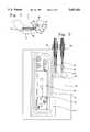
- FIG. 2illustrates a plan view of an electronic system within a production string.
- FIG. 3illustrates an elevation view of an electronic system within a production string.
- FIG. 4illustrates an apparatus for creating a vacuum around electronic components in a well tool.
- the present inventionprovides a novel apparatus and method for extending the life span and reliability of an electronic system within a well tool.
- the inventionis particularly useful in well control and monitoring devices that remain downhole for extended time periods.
- FIG. 1illustrates the decay of an electronic system as a function of time and temperature. As shown, the "life span" decreases exponentially as temperature increases. This principle is mathematically stated by the Arrhenius equation, and broadly defines the performance of semiconductor devices over time. Because of this relationship, the life span of an electronic component is approximately halved for every ten degrees increase in temperature. As shown in FIG. 1, the life span of the integrated circuit population sample is 117.8 years at 80 degrees Centigrade and was reduced to one year at 140 degrees Centigrade.
- FIG. 2shows well completion tool 10 positioned with completion tubing 12. Cavity or recess 14 is milled or otherwise formed in the side of tool 10 and provides a space for other components as described below. Cover 16 is positioned over recess 14, and seal 18 isolates recess 14 from the pressurized well environment. Cover 16 can be attached to tool 10 with conventional techniques such as bolts, clips, or by welding procedures. Cover 16 preferably has a profile that does not provide protrusions or obstructions extending beyond the exterior surface of tool 10 or tubing 12.
- PCBA 20is positioned within recess 14 and can be connected to sensors, control switches, or other equipment useful in well operations. Electrical feed through connector 22 is engaged with bulkhead 24 and permits wire 26 to transmit signals and power between PCBA 20 and equipment outside of recess 14. Wire 26 can extend to the well surface to permit operations to be monitored and controlled from the well surface. Bulkhead 24 permits electrical islolation of PCBA from the ambient well conditions and prevents the movement of fluids therebetween.
- FIG. 3shows an elevation view of tool 10 wherein cover 16 has been removed to show the interior components.
- PCBA 20is connected to wire 26 for the transmission of signals and power.
- Electrical feed through connectors 22provide the bridge between recess 14 and the ambient well environment.
- FIG. 4shows detail of electrical feed through connectors 22 as such components are engaged with tool housing 27.
- Bulkhead 24includes seal 28 for sealing the annulus between bulkhead 24 and tool housing 27, and further includes electrical pin contacts 30 which provide an electrical link between different sections of wire 26.
- Seal 32provides a seal between electrical feed through connector 22 and tool housing 27.
- electrical feed through connector 22includes vacuum nipple 34 which permits a vacuum pump (not shown) to create a vacuum within recess 14.
- a vacuum pump(not shown) to create a vacuum within recess 14.
- such vacuumcan be drawn before bulkhead 24 is sealed with tool housing 27, or can be provided through an independent access port.
- bulkhead 24can be positioned with rod 36 to provide the permanent seal for recess 14 before the vacuum pump is disconnected, and vacuum nipple 34 can be disconnected from contact with tool housing 27 and electrical feed through connector 22. Consequently, a vacuum can be created within recess 14 to remove oxygen, water vapor, and other contaminants from recess 14 which would corrode PCBA 22 and other components within the elctronic system.
- Pressure sensor 40is engaged with PCBA and monitors the pressure within recess 14. If desired, temperature sensors can be attached with PCBA to monitor pressure fluctuations as a function of temperature. The signals provided by pressure sensor 40 are communicated to PCBA 20 and can be communicated with wire 26 to the well surface. If pressure sensor 40 detects that the vacuum within recess 14 becomes less, then such information might indicate the presence of a leak in the integrity of the seal between cover 16 and tool housing 27, or in the integrity of seal 28 between bulkhead 24 and tool housing 27. Consequently, pressure sensor 40 provides a novel technique of monitoring the potential failure of PCBA 20 due to contamination from fluids within the well.
- Pressure sensor 40also provides a mechanism for monitoring the degradation of metallic components in PCBA 20 and in other components within recess 14. As such metallic components deteriorate, gases are released which would reduce the vacuum within recess 14 and would be detected with pressure sensor 40. Over time, such deterioration of the vacuum would permit the long term degration of the PCBA to be evaluated from the well surface without pulling tool 10 from the well.
- This unique feature of the inventionincreases the efficiency of well operations by providing measurable data for predicting failure before the well must be shut down for unscheduled maintenance, and can indicate successful operation to prevent unnecessary workovers for the purpose of checking the downhole equipment.
- recess 14can be filled with an insulating fluid or an inert gas such as argon to prevent chemical deterioration of PCBA 20 and other electrical and electronic components.
- the pressure of the insulating fluid or inert gascan be monitored with pressure sensor to detect leaks in the integrity of recess 14, or to detect deterioration of PCBA 20 and other components within recess 14.
- a gas detectorcan be substituted for pressure sensor 40.
- Such gas detectorcan detect the presence of a gas formed within recess 14 or can detect the leakage of a gas into or away from recess 14. Insulating material such as a nonconductive fluid or an inert gas can be positioned within recess 14.
- the inventionis uniquely suited to test the seal of recess 14 which protects downhole electronic components in a well.
- Recess 14can be tested with a pressure, vacuum, or gas detection technique before the tool is run into a well.
- recess 14can be tested downhole in the well before packers or other downhole equipment are set to position the tool in the well. Testing can include limit tests and can include pressure and temperature cycling of the tool and components within recess 14.
Landscapes
- Physics & Mathematics (AREA)
- Life Sciences & Earth Sciences (AREA)
- Engineering & Computer Science (AREA)
- Geology (AREA)
- Mining & Mineral Resources (AREA)
- Geophysics (AREA)
- Environmental & Geological Engineering (AREA)
- Fluid Mechanics (AREA)
- General Life Sciences & Earth Sciences (AREA)
- Geochemistry & Mineralogy (AREA)
- Examining Or Testing Airtightness (AREA)
Abstract
Description
The present invention relates to the use of electronic systems in a well. More particularly, the present invention relates to a system for extending the life span and reliability of downhole electronic systems in a well, and for monitoring the operation of such electronic systems.
The development of hydrocarbon producing wells requires the installation of well completion equipment to monitor and control fluid flow. The characteristics of the well are monitored by the completion equipment and are transmitted to the surface. The transmitted data is analyzed by a reservoir management system, and completion equipment such as valves, sliding sleeves, packers and other completion tools are operated to control the well.
Electronic systems have been incorporated into well completion equipment. However, electronic systems downhole in a well may not adequately perform over the producing life of a well. If an electronic system should fail, reservoir management data and completion control operations would be interrupted until the equipment is repaired. This failure would interrupt well operations and would increase production costs.
High downhole temperatures in wells substantially reduce the life span of electronics in downhole equipment. Downhole well temperatures can exceed 150 degrees Centigrade, and such temperatures accelerate the corrosion mechanisms affecting electronic systems. Such corrosion mechanisms are accelerated by the presence of oxygen and water vapor in contact with metal components within the electronic systems.
Efforts have been made to mitigate the limitations presented by electronic systems downhole in wells. For example, one system uses fiber optics to operate a downhole pressure gauge system. The gauge senses downhole pressure changes through a response created by changes in the refractive index of a material caused by pressure fluctuations. The change in response is measured at the surface by monitoring changes in the optical signal transmitted from the surface to the downhole gauge and returned to the surface through a fiber optic cable.
Although optical systems may be useful with certain gauges, optical systems are limited because many well conditions and characteristics do not provide a direct optical response. Optical systems are also limited by the amount of power that can be transmitted by an fiber optic cable. Consequently, optical systems cannot perform the same functions provided by electronic systems for the processing of information or regulation of power.
Modern electronic systems are manufactured from a variety of metal alloys and other materials. Such alloys furnish key components for the functionality of the electronic systems, and include solders, metalized portions of the integrated circuits, etched copper alloys of printed circuit boards, and other metalizations used in the construction of printed circuit boards. These materials and compositions deteriorate with time and elevated temperatures.
Insulating flasks have been used in well logging tools to shield electronic components from high well temperatures. Dewar flasks have been used to insulate electronic logging components as the well logging tool is run in a well. While Dewar flasks successfully insulate downhole components for a limited time, the interior flask temperature eventually equalizes with the ambient well temperature and the thermal protection is lost.
Improvements to Dewar flask technology have been proposed to protect downhole electronic. U.S. Pat. No. 3,265,893 to Rabson et al. (1966) described a well logging tool having a thermally conductive heat sink for stabilizing the temperature in the logging tool for up to twenty hours. U.S. Pat. No. 4,671,349 to Wolk (1987) described a heat transfer wick for cooling the components of a well logging instrument for up to six hours during the interval of greatest heat exposure, and U.S. Pat. No. 3,488,970 to Hallenburg (1970) disclosed a module for cooling a water reservoir so that the cooled water could be pumped to transfer heat from the logging tool housing.
None of these techniques propose a system for protecting downhole electronic components over long time periods. Moreover, none of these systems propose a solution for monitoring the deterioration of electronic components within a downhole well tool. Accordingly, there is a need for a system that can perform these functions over the life of the well.
The present invention provides a system and method for containing electronic components in a downhole well tool. The system comprises a cavity within the tool for containing the electronic components. A wire is attached to the electronic components and extends outside of the cavity. A seal between the wire and the tool isolates the cavity from the well, and a vacuum pump engaged with the cavity creates a vacuum within the cavity to remove oxygen and water vapor from contact with the electronic components.
In another embodiment of the invention, a pressure sensor detects the pressure within the cavity, or a gas detector detects the presence of gas, and a signal is generated. A controller positioned at the well surface receives the signal and displays information indicating the cavity pressure or gas information.
The method of the invention comprises the steps of positioning the electronic components in a cavity within the tool and closing the cavity to isolate the cavity from the well. A vacuum is created within the cavity, and the well tool is positioned downhole in the well. The deterioration of the electronic components or leakage within the cavity can be detected by a pressure sensor, and the signals generated by the pressure sensor can be transmitted to a controller at the well surface. In other embodiments, inert gas or insulating fluid can be positioned within the cavity after the vacuum has been created.
FIG. 1 illustrates the decay of electronic components over time when plotted against temperature increases.
FIG. 2 illustrates a plan view of an electronic system within a production string.
FIG. 3 illustrates an elevation view of an electronic system within a production string.
FIG. 4 illustrates an apparatus for creating a vacuum around electronic components in a well tool.
The present invention provides a novel apparatus and method for extending the life span and reliability of an electronic system within a well tool. The invention is particularly useful in well control and monitoring devices that remain downhole for extended time periods.
FIG. 1 illustrates the decay of an electronic system as a function of time and temperature. As shown, the "life span" decreases exponentially as temperature increases. This principle is mathematically stated by the Arrhenius equation, and broadly defines the performance of semiconductor devices over time. Because of this relationship, the life span of an electronic component is approximately halved for every ten degrees increase in temperature. As shown in FIG. 1, the life span of the integrated circuit population sample is 117.8 years at 80 degrees Centigrade and was reduced to one year at 140 degrees Centigrade.
FIG. 2 showswell completion tool 10 positioned withcompletion tubing 12. Cavity orrecess 14 is milled or otherwise formed in the side oftool 10 and provides a space for other components as described below.Cover 16 is positioned overrecess 14, and seal 18 isolates recess 14 from the pressurized well environment.Cover 16 can be attached totool 10 with conventional techniques such as bolts, clips, or by welding procedures.Cover 16 preferably has a profile that does not provide protrusions or obstructions extending beyond the exterior surface oftool 10 ortubing 12.
Printed circuit board ("PCBA") 20 is positioned withinrecess 14 and can be connected to sensors, control switches, or other equipment useful in well operations. Electrical feed throughconnector 22 is engaged withbulkhead 24 andpermits wire 26 to transmit signals and power betweenPCBA 20 and equipment outside ofrecess 14.Wire 26 can extend to the well surface to permit operations to be monitored and controlled from the well surface.Bulkhead 24 permits electrical islolation of PCBA from the ambient well conditions and prevents the movement of fluids therebetween.
FIG. 3 shows an elevation view oftool 10 whereincover 16 has been removed to show the interior components.PCBA 20 is connected to wire 26 for the transmission of signals and power. Electrical feed throughconnectors 22 provide the bridge betweenrecess 14 and the ambient well environment. FIG. 4 shows detail of electrical feed throughconnectors 22 as such components are engaged withtool housing 27.Bulkhead 24 includesseal 28 for sealing the annulus betweenbulkhead 24 andtool housing 27, and further includeselectrical pin contacts 30 which provide an electrical link between different sections ofwire 26. Seal 32 provides a seal between electrical feed throughconnector 22 andtool housing 27.
In operation, electrical feed throughconnector 22 includesvacuum nipple 34 which permits a vacuum pump (not shown) to create a vacuum withinrecess 14. In the embodiment shown in FIG. 4, such vacuum can be drawn beforebulkhead 24 is sealed withtool housing 27, or can be provided through an independent access port. After the vacuum has been created withinrecess 14,bulkhead 24 can be positioned withrod 36 to provide the permanent seal forrecess 14 before the vacuum pump is disconnected, andvacuum nipple 34 can be disconnected from contact withtool housing 27 and electrical feed throughconnector 22. Consequently, a vacuum can be created withinrecess 14 to remove oxygen, water vapor, and other contaminants fromrecess 14 which would corrodePCBA 22 and other components within the elctronic system.
In another embodiment of the invention,recess 14 can be filled with an insulating fluid or an inert gas such as argon to prevent chemical deterioration ofPCBA 20 and other electrical and electronic components. The pressure of the insulating fluid or inert gas can be monitored with pressure sensor to detect leaks in the integrity ofrecess 14, or to detect deterioration ofPCBA 20 and other components withinrecess 14.
In alternative embodiments of the invention, a gas detector can be substituted forpressure sensor 40. Such gas detector can detect the presence of a gas formed withinrecess 14 or can detect the leakage of a gas into or away fromrecess 14. Insulating material such as a nonconductive fluid or an inert gas can be positioned withinrecess 14. The invention is uniquely suited to test the seal ofrecess 14 which protects downhole electronic components in a well.Recess 14 can be tested with a pressure, vacuum, or gas detection technique before the tool is run into a well. Additionally,recess 14 can be tested downhole in the well before packers or other downhole equipment are set to position the tool in the well. Testing can include limit tests and can include pressure and temperature cycling of the tool and components withinrecess 14. By providing a test apparatus and method to test the viability of the recess seal protecting downhole components, failures occuring during installation can be detected before well equipment is committed in the well.
Although the invention has been described in terms of certain preferred embodiments, it will be apparent to those of ordinary skill in the art that various modifications and improvements can be made to the inventive concepts herein without departing from the scope of the invention. The embodiments described herein are merely illustrative of the inventive concepts and should not be interpreted as limiting the scope of the invention.
Claims (12)
1. A system for containing electronic components in a downhole well tool, comprising:
a cavity within the tool for containing the electronic components;
a wire attached to the electronic components which extends outside of said cavity;
a seal between said wire and the tool for isolating said cavity from the well;
a vacuum pump engaged with said cavity for creating a vacuum within said cavity; and
a gas sensor engaged with said wire and in contact with said cavity for detecting the presence of a gas within said cavity.
2. A system for containing electronic components in a downhole well tool, comprising:
a cavity within the tool for containing the electronic components;
a wire attached to the electronic components which extends outside of said cavity;
a seal between said wire and the tool for isolating said cavity from the well;
a vacuum pump engaged with said cavity for creating, a vacuum within said cavity; and
a pressure sensor in contact with said cavity for detecting the pressure within said cavity, wherein said pressure sensor is engaged with said wire to transmit electrical signals indicating the pressure within said cavity.
3. A system for containing electronic components in a downhole well tool, comprising:
a cavity within the tool for containing the electronic components;
a wire attached to the electronic components which extends outside of said cavity;
a seal between said wire and the tool for isolating said cavity from the well;
a vacuum pump engaged with said cavity for creating a vacuum within said cavity;
a valve between said vacuum pump and the tool for permitting the removal of said vacuum pump from engagement with said cavity; and
an inert gas within said cavity for contacting the electronic components.
4. A system for containing electronic components in a downhole well tool, comprising:
a cavity within the tool for containing the electronic components;
a wire attached to the electronic components which extends outside of said, cavity;
a seal between said wire and the tool for isolating said cavity from the well;
a vacuum pump engaged with said cavity for creating a vacuum within said cavity;
a valve between said vacuum pump and the tool for permitting the removal of said vacuum pump from engagement with said cavity; and
an insulating fluid within said cavity for contacting the electronic components.
5. A system for monitoring a downhole well tool having electronic components with the tool; comprising:
a cavity within the tool for containing the electronic components, wherein said cavity is isolated from the well;
a pressure sensor in contact with cavity for detecting the pressure within said cavity and for generating signals indicating the cavity pressure;
a wire engaged with said pressure sensor for transmitting the signals generated by said pressure sensor; and
a controller positioned at the well surface and engaged with said wire for receiving the signals generated by said pressure sensor and for displaying information indicating the pressure changes identified by such signals.
6. A system as recited in claim 5, wherein said electronic components are connected between said pressure sensor and said wire.
7. A system as recited in claim 5, further comprising an inert gas within said cavity for contacting the electronic components.
8. A system as recited in claim 5, further comprising an insulating fluid within said cavity for contacting the electronic components.
9. A system for monitoring a downhole well tool having electronic components with the tool, comprising:
a cavity within the tool for containing the electronic components, wherein said cavity is isolated from the well;
a pressure sensor in contact with said cavity for detecting the pressure within said cavity and for generating signals indicating the cavity pressure;
a wire engaged with said pressure sensor for transmitting the signals generated by said pressure sensor;
a controller positioned at the well surface and engaged with said wire for receiving the signals generated by said pressure sensor and for displaying information indicating the pressure changes identified by such signals; and
a vacuum pump engaged with said cavity for creating a vacuum within said cavity.
10. A system as recited in claim 9, further comprising a valve between said vacuum pump and said cavity for permitting the removal of said vacuum pump from engagement with said cavity.
11. A method for containing electronic components in a well tool, comprising the steps of:
positioning the electronic components in a cavity within the tool;
closing the cavity to isolate the cavity from the downhole well environment;
positioning the well tool downhole in a well;
positioning a pressure sensor in contact with said cavity for detecting the pressure within said cavity and for generating signals indicating such pressure;
transmitting the signals generated by said pressure sensor to a controller at the well surface; and
operating said controller to display information indicating the pressure within said cavity.
12. A method for containing electronic components in a well tool, comprising the steps of:
positioning the electronic components in a cavity within the tool;
closing the cavity to isolate the cavity from the downhole well environment;
positioning the well tool downhole in a well;
monitoring said cavity to identify environmental changes within said cavity; and positioning a gas detector in contact with said cavity to detect gas within said cavity.
Priority Applications (1)
| Application Number | Priority Date | Filing Date | Title |
|---|---|---|---|
| US08/533,282US5647435A (en) | 1995-09-25 | 1995-09-25 | Containment of downhole electronic systems |
Applications Claiming Priority (1)
| Application Number | Priority Date | Filing Date | Title |
|---|---|---|---|
| US08/533,282US5647435A (en) | 1995-09-25 | 1995-09-25 | Containment of downhole electronic systems |
Publications (1)
| Publication Number | Publication Date |
|---|---|
| US5647435Atrue US5647435A (en) | 1997-07-15 |
Family
ID=24125273
Family Applications (1)
| Application Number | Title | Priority Date | Filing Date |
|---|---|---|---|
| US08/533,282Expired - Fee RelatedUS5647435A (en) | 1995-09-25 | 1995-09-25 | Containment of downhole electronic systems |
Country Status (1)
| Country | Link |
|---|---|
| US (1) | US5647435A (en) |
Cited By (16)
| Publication number | Priority date | Publication date | Assignee | Title |
|---|---|---|---|---|
| US6041860A (en)* | 1996-07-17 | 2000-03-28 | Baker Hughes Incorporated | Apparatus and method for performing imaging and downhole operations at a work site in wellbores |
| US6220346B1 (en) | 1999-05-29 | 2001-04-24 | Halliburton Energy Services, Inc. | Thermal insulation vessel |
| US6257332B1 (en) | 1999-09-14 | 2001-07-10 | Halliburton Energy Services, Inc. | Well management system |
| US6688860B2 (en) | 2001-06-18 | 2004-02-10 | Schlumberger Technology Corporation | Protector for electrical submersible pumps |
| US20050269092A1 (en)* | 2004-04-23 | 2005-12-08 | Vinegar Harold J | Vacuum pumping of conductor-in-conduit heaters |
| US20070074872A1 (en)* | 2005-09-30 | 2007-04-05 | Schlumberger Technology Corporation | Apparatus, Pumping System Incorporating Same, and Methods of Protecting Pump Components |
| US20070289740A1 (en)* | 1998-12-21 | 2007-12-20 | Baker Hughes Incorporated | Apparatus and Method for Managing Supply of Additive at Wellsites |
| US20080262737A1 (en)* | 2007-04-19 | 2008-10-23 | Baker Hughes Incorporated | System and Method for Monitoring and Controlling Production from Wells |
| US20080257544A1 (en)* | 2007-04-19 | 2008-10-23 | Baker Hughes Incorporated | System and Method for Crossflow Detection and Intervention in Production Wellbores |
| US20080262735A1 (en)* | 2007-04-19 | 2008-10-23 | Baker Hughes Incorporated | System and Method for Water Breakthrough Detection and Intervention in a Production Well |
| US20080262736A1 (en)* | 2007-04-19 | 2008-10-23 | Baker Hughes Incorporated | System and Method for Monitoring Physical Condition of Production Well Equipment and Controlling Well Production |
| US7929144B1 (en) | 2008-12-16 | 2011-04-19 | The United States Of America As Represented By The Administrator Of The National Aeronautics And Space Administration | Optical system and method for gas detection and monitoring |
| US20180238141A1 (en)* | 2015-09-22 | 2018-08-23 | Halliburton Energy Services, Inc. | Downhole Tool with Assembly for Determining Seal Integrity |
| CN109577949A (en)* | 2018-12-05 | 2019-04-05 | 西安石油大学 | Utilize the device and method of pressure transmission medium transmitting pressure to underground electronic component |
| US20190242808A1 (en)* | 2017-12-20 | 2019-08-08 | Well Diver, Inc. | Corrosion Sensor |
| CN116092768A (en)* | 2023-04-12 | 2023-05-09 | 江西联创光电超导应用有限公司 | A low-temperature magnet Dewar device and vacuum degree control method |
Citations (6)
| Publication number | Priority date | Publication date | Assignee | Title |
|---|---|---|---|---|
| US4093854A (en)* | 1975-05-22 | 1978-06-06 | Schlumberger Technology Corporation | Well logging sonde including a linear particle accelerator |
| US4629888A (en)* | 1985-10-18 | 1986-12-16 | Piero Wolk | Well logging tool for hot well bores |
| US4671349A (en)* | 1985-03-18 | 1987-06-09 | Piero Wolk | Well logging electronics cooling system |
| US4673652A (en)* | 1982-10-12 | 1987-06-16 | Baker Oil Tools, Inc. | Method of testing and reconditioning insulating tubular conduits |
| US5061849A (en)* | 1988-04-01 | 1991-10-29 | Baker Hughes Incorporated | Externally mounted radioactivity detector for MWD employing radial inline scintillator and photomultiplier tube |
| US5530358A (en)* | 1994-01-25 | 1996-06-25 | Baker Hughes, Incorporated | Method and apparatus for measurement-while-drilling utilizing improved antennas |
- 1995
- 1995-09-25USUS08/533,282patent/US5647435A/ennot_activeExpired - Fee Related
Patent Citations (6)
| Publication number | Priority date | Publication date | Assignee | Title |
|---|---|---|---|---|
| US4093854A (en)* | 1975-05-22 | 1978-06-06 | Schlumberger Technology Corporation | Well logging sonde including a linear particle accelerator |
| US4673652A (en)* | 1982-10-12 | 1987-06-16 | Baker Oil Tools, Inc. | Method of testing and reconditioning insulating tubular conduits |
| US4671349A (en)* | 1985-03-18 | 1987-06-09 | Piero Wolk | Well logging electronics cooling system |
| US4629888A (en)* | 1985-10-18 | 1986-12-16 | Piero Wolk | Well logging tool for hot well bores |
| US5061849A (en)* | 1988-04-01 | 1991-10-29 | Baker Hughes Incorporated | Externally mounted radioactivity detector for MWD employing radial inline scintillator and photomultiplier tube |
| US5530358A (en)* | 1994-01-25 | 1996-06-25 | Baker Hughes, Incorporated | Method and apparatus for measurement-while-drilling utilizing improved antennas |
Cited By (23)
| Publication number | Priority date | Publication date | Assignee | Title |
|---|---|---|---|---|
| US6041860A (en)* | 1996-07-17 | 2000-03-28 | Baker Hughes Incorporated | Apparatus and method for performing imaging and downhole operations at a work site in wellbores |
| US20070289740A1 (en)* | 1998-12-21 | 2007-12-20 | Baker Hughes Incorporated | Apparatus and Method for Managing Supply of Additive at Wellsites |
| US8682589B2 (en)* | 1998-12-21 | 2014-03-25 | Baker Hughes Incorporated | Apparatus and method for managing supply of additive at wellsites |
| US6220346B1 (en) | 1999-05-29 | 2001-04-24 | Halliburton Energy Services, Inc. | Thermal insulation vessel |
| US6257332B1 (en) | 1999-09-14 | 2001-07-10 | Halliburton Energy Services, Inc. | Well management system |
| US20110014071A1 (en)* | 2001-06-18 | 2011-01-20 | Schlumberger Technology Corporation | Protector for electrical submersible pumps |
| US6688860B2 (en) | 2001-06-18 | 2004-02-10 | Schlumberger Technology Corporation | Protector for electrical submersible pumps |
| US20050269092A1 (en)* | 2004-04-23 | 2005-12-08 | Vinegar Harold J | Vacuum pumping of conductor-in-conduit heaters |
| US7424915B2 (en)* | 2004-04-23 | 2008-09-16 | Shell Oil Company | Vacuum pumping of conductor-in-conduit heaters |
| US20070074872A1 (en)* | 2005-09-30 | 2007-04-05 | Schlumberger Technology Corporation | Apparatus, Pumping System Incorporating Same, and Methods of Protecting Pump Components |
| US7654315B2 (en) | 2005-09-30 | 2010-02-02 | Schlumberger Technology Corporation | Apparatus, pumping system incorporating same, and methods of protecting pump components |
| US20080262737A1 (en)* | 2007-04-19 | 2008-10-23 | Baker Hughes Incorporated | System and Method for Monitoring and Controlling Production from Wells |
| US20080262736A1 (en)* | 2007-04-19 | 2008-10-23 | Baker Hughes Incorporated | System and Method for Monitoring Physical Condition of Production Well Equipment and Controlling Well Production |
| US7711486B2 (en) | 2007-04-19 | 2010-05-04 | Baker Hughes Incorporated | System and method for monitoring physical condition of production well equipment and controlling well production |
| US7805248B2 (en) | 2007-04-19 | 2010-09-28 | Baker Hughes Incorporated | System and method for water breakthrough detection and intervention in a production well |
| US20080257544A1 (en)* | 2007-04-19 | 2008-10-23 | Baker Hughes Incorporated | System and Method for Crossflow Detection and Intervention in Production Wellbores |
| US20080262735A1 (en)* | 2007-04-19 | 2008-10-23 | Baker Hughes Incorporated | System and Method for Water Breakthrough Detection and Intervention in a Production Well |
| US7929144B1 (en) | 2008-12-16 | 2011-04-19 | The United States Of America As Represented By The Administrator Of The National Aeronautics And Space Administration | Optical system and method for gas detection and monitoring |
| US20180238141A1 (en)* | 2015-09-22 | 2018-08-23 | Halliburton Energy Services, Inc. | Downhole Tool with Assembly for Determining Seal Integrity |
| US10774614B2 (en)* | 2015-09-22 | 2020-09-15 | Halliburton Energy Services, Inc. | Downhole tool with assembly for determining seal integrity |
| US20190242808A1 (en)* | 2017-12-20 | 2019-08-08 | Well Diver, Inc. | Corrosion Sensor |
| CN109577949A (en)* | 2018-12-05 | 2019-04-05 | 西安石油大学 | Utilize the device and method of pressure transmission medium transmitting pressure to underground electronic component |
| CN116092768A (en)* | 2023-04-12 | 2023-05-09 | 江西联创光电超导应用有限公司 | A low-temperature magnet Dewar device and vacuum degree control method |
Similar Documents
| Publication | Publication Date | Title |
|---|---|---|
| US5647435A (en) | Containment of downhole electronic systems | |
| CA1229242A (en) | Drill stem testing apparatus with multiple pressure sensing ports | |
| US4976142A (en) | Borehole pressure and temperature measurement system | |
| EP2769051B1 (en) | Method for installing and retrieving a well monitoring apparatus | |
| US6442304B1 (en) | Apparatus and method for protecting devices, especially fibre optic devices, in hostile environments | |
| EP2329106B1 (en) | Method, device, and system for determining water or liquid in the annulus of a flexible riser or flowline | |
| US6766703B1 (en) | Apparatus and method for enhancing remote sensor performance and utility | |
| BRPI1010460B1 (en) | method for monitoring the condition of a device located in a submerged installation and a condition monitoring means for monitoring a component of a submerged installation | |
| NO340199B1 (en) | Device for monitoring a drilling or core drilling operation and installation comprising such a device | |
| CN101929912A (en) | Monitoring of undesirable fluid ingress into subsea control modules | |
| EP3193148A1 (en) | Pressure sensor | |
| EP0695853B1 (en) | Sensor protection from downhole fluids | |
| CN111076853A (en) | A short-base sensor for monitoring the stress of ship structure and using method thereof | |
| US20060153487A1 (en) | System and method for packaging a fibre optic sensor | |
| US10168371B2 (en) | System and methods for determining the impact of moisture on dielectric sealing material of downhole electrical feedthrough packages | |
| CN106950171A (en) | Downhole well corrosion monitoring device | |
| CN214424490U (en) | Wireless data transmission real-time monitor | |
| JP3362599B2 (en) | Sodium leak prevention thermometer | |
| EP1070196B1 (en) | Apparatus and method for enhancing remote sensor performance | |
| CN120798298A (en) | Downhole multi-parameter measuring tool and using method thereof | |
| CN208673990U (en) | Digital sulfur hexafluoride gas density relay | |
| Guan et al. | Prediction of Sensor System Reliability. | |
| JP4103028B2 (en) | Diaphragm seal type differential pressure measuring device | |
| Veneruso et al. | High temperature instrumentation for geothermal applications | |
| LOS | HIGH TEMPERATURE TESTING OF THE EDCON BOREHOLE GRAVITY HOUSING SYSTEM CONDUCTED AT LOS ALAMOS NATIONAL LABORATORIES |
Legal Events
| Date | Code | Title | Description |
|---|---|---|---|
| AS | Assignment | Owner name:PES, INC., TEXAS Free format text:ASSIGNMENT OF ASSIGNORS INTEREST;ASSIGNORS:OWENS, STEVE;ELLIOT, GARY;REEL/FRAME:008188/0035 Effective date:19960903 | |
| FEPP | Fee payment procedure | Free format text:PAYOR NUMBER ASSIGNED (ORIGINAL EVENT CODE: ASPN); ENTITY STATUS OF PATENT OWNER: LARGE ENTITY | |
| FEPP | Fee payment procedure | Free format text:PAT HLDR NO LONGER CLAIMS SMALL ENT STAT AS SMALL BUSINESS (ORIGINAL EVENT CODE: LSM2); ENTITY STATUS OF PATENT OWNER: LARGE ENTITY | |
| FPAY | Fee payment | Year of fee payment:4 | |
| AS | Assignment | Owner name:WELLDYNAMICS, INC., TEXAS Free format text:CHANGE OF NAME;ASSIGNOR:PES, INC.;REEL/FRAME:012530/0112 Effective date:20010426 | |
| REMI | Maintenance fee reminder mailed | ||
| LAPS | Lapse for failure to pay maintenance fees | ||
| STCH | Information on status: patent discontinuation | Free format text:PATENT EXPIRED DUE TO NONPAYMENT OF MAINTENANCE FEES UNDER 37 CFR 1.362 | |
| FP | Lapsed due to failure to pay maintenance fee | Effective date:20050715 |