US5647260A - Roller cutting machine - Google Patents
Roller cutting machineDownload PDFInfo
- Publication number
- US5647260A US5647260AUS08/536,801US53680195AUS5647260AUS 5647260 AUS5647260 AUS 5647260AUS 53680195 AUS53680195 AUS 53680195AUS 5647260 AUS5647260 AUS 5647260A
- Authority
- US
- United States
- Prior art keywords
- pressure roller
- roller
- drive
- assembly
- die
- Prior art date
- Legal status (The legal status is an assumption and is not a legal conclusion. Google has not performed a legal analysis and makes no representation as to the accuracy of the status listed.)
- Expired - Lifetime
Links
Images


Classifications
- F—MECHANICAL ENGINEERING; LIGHTING; HEATING; WEAPONS; BLASTING
- F16—ENGINEERING ELEMENTS AND UNITS; GENERAL MEASURES FOR PRODUCING AND MAINTAINING EFFECTIVE FUNCTIONING OF MACHINES OR INSTALLATIONS; THERMAL INSULATION IN GENERAL
- F16P—SAFETY DEVICES IN GENERAL; SAFETY DEVICES FOR PRESSES
- F16P3/00—Safety devices acting in conjunction with the control or operation of a machine; Control arrangements requiring the simultaneous use of two or more parts of the body
- F16P3/12—Safety devices acting in conjunction with the control or operation of a machine; Control arrangements requiring the simultaneous use of two or more parts of the body with means, e.g. feelers, which in case of the presence of a body part of a person in or near the danger zone influence the control or operation of the machine
- F16P3/125—Guards for rolls in calendering or other roll machines, e.g. nip guards, finger guards
- B—PERFORMING OPERATIONS; TRANSPORTING
- B26—HAND CUTTING TOOLS; CUTTING; SEVERING
- B26F—PERFORATING; PUNCHING; CUTTING-OUT; STAMPING-OUT; SEVERING BY MEANS OTHER THAN CUTTING
- B26F1/00—Perforating; Punching; Cutting-out; Stamping-out; Apparatus therefor
- B26F1/38—Cutting-out; Stamping-out
- B26F1/40—Cutting-out; Stamping-out using a press, e.g. of the ram type
- B26F1/42—Cutting-out; Stamping-out using a press, e.g. of the ram type having a pressure roller
- Y—GENERAL TAGGING OF NEW TECHNOLOGICAL DEVELOPMENTS; GENERAL TAGGING OF CROSS-SECTIONAL TECHNOLOGIES SPANNING OVER SEVERAL SECTIONS OF THE IPC; TECHNICAL SUBJECTS COVERED BY FORMER USPC CROSS-REFERENCE ART COLLECTIONS [XRACs] AND DIGESTS
- Y10—TECHNICAL SUBJECTS COVERED BY FORMER USPC
- Y10S—TECHNICAL SUBJECTS COVERED BY FORMER USPC CROSS-REFERENCE ART COLLECTIONS [XRACs] AND DIGESTS
- Y10S83/00—Cutting
- Y10S83/01—Safety devices
- Y—GENERAL TAGGING OF NEW TECHNOLOGICAL DEVELOPMENTS; GENERAL TAGGING OF CROSS-SECTIONAL TECHNOLOGIES SPANNING OVER SEVERAL SECTIONS OF THE IPC; TECHNICAL SUBJECTS COVERED BY FORMER USPC CROSS-REFERENCE ART COLLECTIONS [XRACs] AND DIGESTS
- Y10—TECHNICAL SUBJECTS COVERED BY FORMER USPC
- Y10T—TECHNICAL SUBJECTS COVERED BY FORMER US CLASSIFICATION
- Y10T83/00—Cutting
- Y10T83/849—With signal, scale, or indicator
- Y10T83/85—Signal; e.g., alarm
- Y—GENERAL TAGGING OF NEW TECHNOLOGICAL DEVELOPMENTS; GENERAL TAGGING OF CROSS-SECTIONAL TECHNOLOGIES SPANNING OVER SEVERAL SECTIONS OF THE IPC; TECHNICAL SUBJECTS COVERED BY FORMER USPC CROSS-REFERENCE ART COLLECTIONS [XRACs] AND DIGESTS
- Y10—TECHNICAL SUBJECTS COVERED BY FORMER USPC
- Y10T—TECHNICAL SUBJECTS COVERED BY FORMER US CLASSIFICATION
- Y10T83/00—Cutting
- Y10T83/869—Means to drive or to guide tool
- Y10T83/8752—Tool moves work to and against cooperating tool
- Y—GENERAL TAGGING OF NEW TECHNOLOGICAL DEVELOPMENTS; GENERAL TAGGING OF CROSS-SECTIONAL TECHNOLOGIES SPANNING OVER SEVERAL SECTIONS OF THE IPC; TECHNICAL SUBJECTS COVERED BY FORMER USPC CROSS-REFERENCE ART COLLECTIONS [XRACs] AND DIGESTS
- Y10—TECHNICAL SUBJECTS COVERED BY FORMER USPC
- Y10T—TECHNICAL SUBJECTS COVERED BY FORMER US CLASSIFICATION
- Y10T83/00—Cutting
- Y10T83/95—Machine frame
- Y10T83/96—Guard
Definitions
- the present inventionrelates generally to die cutting apparatus, and more particularly to an improved roller die cutting machine.
- Rotary dies and rotary die cutting apparatushave been utilized for many years for cutting shapes and patterns from continuous sheet stock material.
- Rotary die cutting machinesare typically expensive pieces of equipment, and are also expensive to operate, and are therefore unsuitable for smaller tasks.
- the roller die cutting machineincluded a plurality of parallel and spaced apart support rollers upon which a die plate was movably supported.
- a pressure roller mounted above the support rollerswas rotatable to draw a die covered by a piece of paper or card stock between the pressure roller and the support rollers. As the pressure roller rotated the crown of the pressure roller would impart a force directly on the stock causing the blades of the die to cut through the stock.
- roller die cutting machinehas worked well for its intended purposes, the inventor herein has improved upon the machine with various safety features.
- Another objectis to provide a roller cutting machine with an audible alarm to indicate the presence of a foreign object located near the cutting operation of the roller on the die.
- a further objectis to provide a roller die cutting machine with direct drive capabilities between the crank handle and the pressure roller.
- Still another object of the present inventionis to provide a roller die cutting machine which maintains uniform cutting pressure transversely along the die.
- Still another object of the present inventionis to provide a roller die cutting machine which is simple to operate, economical to manufacture, and refined in appearance.
- the roller die cutting machine of the present inventionincludes a base having a drive roller assembly generally centered thereon between opposing side edges.
- a first tableis located between the drive roller assembly and the first side edge to support a die assembly, and a second table is supported on the base opposite the first table to support a die assembly.
- a crankis connected through a set of gears to the pressure roller to rotate the pressure roller and to draw a die assembly through the drive roller assembly, to thereby cut stock positioned on the die assembly.
- a cover on the drive roller assemblyincludes a pair of inwardly projecting lips which will contact the pressure roller and produce an audible sound as a consumer's hand approaches the cutting location of the pressure roller.
- FIG. 1is a perspective view of the roller die cutting machine of the present invention
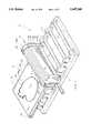
- FIG. 2is an exploded perspective view of the apparatus
- FIG. 3is an enlarged vertical sectional view through the apparatus
- FIG. 4is a view similar to FIG. 3, with the die moved into operable position under the pressure roller.
- the roller cutting machine of the present inventionis designated generally at 10 and includes a drive roller assembly 12 mounted generally centrally on a base 14, which receives a die assembly 16 for cutting shapes from various types of paper stock (shown in hidden lines at 18).
- a conventional die assembly 16includes a generally planar wood base 20 with a flat upper surface 20a, and a steel rule 22 projecting upwardly from the upper face 20a of base 20 and formed into a desired shape.
- rule 22is formed in the shape of an apple, and includes an upper cutting edge 22a lying within a single plane at a predetermined distance above the upper surface 20a of base 20.
- a shallow tray 24is provided to receive one or more die assemblies 16 and support them as they are passed through drive roller assembly 12.
- drive roller assembly 12includes an elongated pressure roller 26 rotatably mounted between opposing forward and rearward stanchions 28 and 30, and spaced parallel to and above the upper surface 14a of base 14, generally transverse to the longitudinal axis of base 14.
- Three support rollers 32, 34 and 36are rotatably mounted between forward and rearward stanchions 28 and 30, parallel with one another and with pressure roller 26, and spaced below pressure roller 26.
- Support rollers 32, 34 and 36will support tray 24 and die assembly 16 (shown in FIG. 1) as die assembly 16 is drawn through drive roller assembly 12 under pressure roller 26, as described in more detail hereinbelow.
- Stanchion 28is formed from a pair of cooperating forward and rearward plates 28a and 28b respectively.
- Pressure roller 26includes a central shaft 38 projecting through an aperture 40 in rearward plate 28b for rotatable support therein.
- a circular depression 42 formed in the forward face of rearward plates 28bis sized to receive a gear 44 therein concentric with and connected to shaft 38.
- a key 46 on shaft 38co-acts with a slot 48 in gear 44 such that gear 44 rotates with shaft 38.
- a smaller circular depression 50is formed in the forward face of rearward plate 28b, spaced upwardly from shaft 38 and located such that a small drive gear 52 mounted within depression 50 will engage gear 44.
- Drive gear 52includes a drive pin 54 affixed thereto and extending coaxially therethrough to serve as both a bearing and drive mechanism.
- a forward end 54a of drive pin 54projects through an opening 56 in forward plate 28a, and has opposing flattened shoulders 58 formed thereon which project outwardly from a forward face of forward plate 28a.
- a crank 60has an arm 62 with an elongated slot 64 formed in one end thereof which engages the projecting shoulders 58 of drive pin 54 to rotate drive pin 54 upon movement of arm 62.
- a screw 66retains crank arm 62 on the forward end of drive pin 54, and a handle 68 projects forwardly from the second end of crank arm 62 so as to rotate drive pin 54, drive gear 52, gear 44, shaft 38, and thereby rotate pressure roller 26.
- Forward plate 28ais attached to the forward face of rearward plate 28b by a plurality of screws 70, to retain gears 52 and 44 within depressions 50 and 42 respectively.
- a pair of screws 72are inserted upwardly through base 14 and threaded into the bottom of rearward plate 28b, to retain stanchion 28 in position.
- a similar pair of screwsare provided to retain rearward stanchion 30 in position on base 14. In this way, pressure roller 26 and/or support rollers 32, 34 and 36 may be removed and replaced by removing either forward or rearward stanchions 28 or 30.
- a series of three idler rollers 74, 76 and 78are rotatably mounted in parallel spaced apart fashion, with their axes parallel and co-planar with the longitudinal axes of support rollers 32, 34 and 36. As shown in FIG. 2, idler roller 74, 76 and 78 are generally uniformly spaced between drive roller assembly 12 and one side edge 14b of base 14.
- a second set of idler rollers 80, 82 and 84are rotatably mounted to base 14 in uniformly spaced between pressure roller 26 and the opposing side edge 14c of base 14. Idler rollers 80, 82 and 84 are parallel, spaced apart, and have their rotational axes co-planar with the rotational axes of rollers 74, 76 and 78.
- idler rollers 74, 76 and 78form a "table" upon which tray 24 (shown in FIG. 1) is supported prior to entry into drive roller assembly 12 and rollers 80, 82 and 84 form a second table for supporting tray 24 after exiting drive roller assembly 12.
- a protective cover 86is provided for drive roller assembly 12, to prevent the consumer from catching fingers in the drive roller assembly.
- Cover 86is generally arch-shaped in cross-section, and includes a curved roof portion 88 and opposing generally vertical panels 90 and 92 extending downwardly from the side edges of roof 88.
- Each vertical panel 90 and 92includes an inwardly directed lip 94 and 96, respectively, the juncture of lips 94 and 96 with vertical panels 90 and 92 forming lower edges 90a and 92a respectively.
- the forward face 30a of rear stanchion 30includes an arch-shaped depression 98 formed along its upper edge, having a vertical arch-shaped forward face 98a and a semi-cylindrical shoulder portion 98b, shoulder portion 98b shaped to receive the rearward end of roof portion 88 of cover 86 thereon.
- Vertical panels 90 and 92have a length, as measured between the forward and rearward ends, slightly less than the length of roof portion 88, thereby forming forward and rearward shoulders 100 at the forward and rearward junctures of roof 88 with panel 90 and shoulders 102 at the junctures at panel 92 with roof 88. As shown in FIG.
- the length of panels 90 and 92is equal to the distance between the forward face 30a of rearward stanchion 30 and the rearward face of forward stanchion 28 for a snug fit therebetween.
- the length of roof portion 88 of cover 86fits snugly between the forward face 98a of arch-shaped depression 98 (on rearward stanchion 30) and the vertical face 104a of a similar arch-shaped depression 104 on the upper end of the rearward face of forward stanchion 28.
- a pair of horizontally oriented pins 106project from the vertical face 98a of depression 98 adjacent and spaced from the lower ends 98c of depression 98, pins 106 being spaced from depression shoulder 98b a distance substantially equal to the thickness of roof portion 88 of cover 86. In this way, cover 86 is snugly inserted between pins 106 and depression shoulder 98b, to retain the cover in position.
- a similar pair of pins 108are provided on forward stanchion 28.
- FIG. 3shows die assembly 16 on tray 24 with a sheet of paper or other stock material 20 placed on top of rule 22, in preparation for cutting.
- Tray 24is supported on idler rollers 74 (not shown), 76 (not shown), 78, and support roller 32.
- An operatorwill typically hold paper stock 20 in position with the hand 110 until the paper stock is gripped in drive roller assembly 12.
- pressure roller 26preferably has an outer resilient compressible surface 26a with its lower crown 26b located above support rollers 32, 34 and 36 so as to engage the cutting edge 22a of rule 22, as die assembly 16 is drawn through drive roller assembly 12.
- rotating crank handle 68will cause pressure roller 26 to rotate and draw die assembly 16 between roller 26 and support rollers 32, 34 and 36.
- the cutting edge 22a of die rule 22cuts through the paper stock 20 and presses into the pressure roller surface 26a making cuts through the paper stock 20.
- the die assembly 16 leaves drive roller assembly 12it is supported on idler rollers 80, 82 and 84, as shown in FIG. 1.
- the lower edges 90a and 92a of vertical panels 90 and 92are located a distance above die assembly 16 to prevent the insertion of the fingers under cover 86. Preferably, this distance is one-quarter inch or less.
- cover 86is preferably formed of a stiff plastic material, but which is flexible.
- inwardly projecting lips 94 and 96extend a distance and at an angle such that an inward edge 94a and 96a will be bent into frictional contact with the outer surface 26a if hand 110 is pressed against either vertical panel 90 or vertical panel 92, as shown in FIG. 4.
- the frictional contact of lip edge 96a (or lip edge 94a) with the hard rubber surface 26a of pressure roller 26causes an audible sound to occur if the roller 26 continues to rotate, thereby alerting the operator that the hand 110 is too close to pressure roller 26, and endanger of being pinched or otherwise hurt.
Landscapes
- Engineering & Computer Science (AREA)
- General Engineering & Computer Science (AREA)
- Mechanical Engineering (AREA)
- Life Sciences & Earth Sciences (AREA)
- Forests & Forestry (AREA)
- Perforating, Stamping-Out Or Severing By Means Other Than Cutting (AREA)
Abstract
Description
The present invention relates generally to die cutting apparatus, and more particularly to an improved roller die cutting machine.
Rotary dies and rotary die cutting apparatus have been utilized for many years for cutting shapes and patterns from continuous sheet stock material. Rotary die cutting machines are typically expensive pieces of equipment, and are also expensive to operate, and are therefore unsuitable for smaller tasks.
In order to fulfill a need by educational institutions and the home consumer, the inventor herein devised a pressure roller cutting machine which was simple to operate, economical to manufacture, and inexpensive for the purchaser. The roller die cutting machine included a plurality of parallel and spaced apart support rollers upon which a die plate was movably supported. A pressure roller mounted above the support rollers was rotatable to draw a die covered by a piece of paper or card stock between the pressure roller and the support rollers. As the pressure roller rotated the crown of the pressure roller would impart a force directly on the stock causing the blades of the die to cut through the stock.
While the roller die cutting machine has worked well for its intended purposes, the inventor herein has improved upon the machine with various safety features.
It is therefore a general object of the present invention to provide an improved roller die cutting machine.
Another object is to provide a roller cutting machine with an audible alarm to indicate the presence of a foreign object located near the cutting operation of the roller on the die.
A further object is to provide a roller die cutting machine with direct drive capabilities between the crank handle and the pressure roller.
Still another object of the present invention is to provide a roller die cutting machine which maintains uniform cutting pressure transversely along the die.
Still another object of the present invention is to provide a roller die cutting machine which is simple to operate, economical to manufacture, and refined in appearance.
These and other objects will be apparent to those skilled in the art.
The roller die cutting machine of the present invention includes a base having a drive roller assembly generally centered thereon between opposing side edges. A first table is located between the drive roller assembly and the first side edge to support a die assembly, and a second table is supported on the base opposite the first table to support a die assembly. A crank is connected through a set of gears to the pressure roller to rotate the pressure roller and to draw a die assembly through the drive roller assembly, to thereby cut stock positioned on the die assembly. A cover on the drive roller assembly includes a pair of inwardly projecting lips which will contact the pressure roller and produce an audible sound as a consumer's hand approaches the cutting location of the pressure roller.
FIG. 1 is a perspective view of the roller die cutting machine of the present invention;
FIG. 2 is an exploded perspective view of the apparatus;
FIG. 3 is an enlarged vertical sectional view through the apparatus;
FIG. 4 is a view similar to FIG. 3, with the die moved into operable position under the pressure roller.
Referring now to the drawings, in which similar or corresponding parts are identified with the same reference numeral, and more particularly to FIG. 1, the roller cutting machine of the present invention is designated generally at 10 and includes adrive roller assembly 12 mounted generally centrally on abase 14, which receives adie assembly 16 for cutting shapes from various types of paper stock (shown in hidden lines at 18).
Aconventional die assembly 16 includes a generallyplanar wood base 20 with a flatupper surface 20a, and asteel rule 22 projecting upwardly from theupper face 20a ofbase 20 and formed into a desired shape. As shown in FIG. 1,rule 22 is formed in the shape of an apple, and includes anupper cutting edge 22a lying within a single plane at a predetermined distance above theupper surface 20a ofbase 20. For convenience, ashallow tray 24 is provided to receive one or moredie assemblies 16 and support them as they are passed throughdrive roller assembly 12.
Referring now to FIG. 2,drive roller assembly 12 includes anelongated pressure roller 26 rotatably mounted between opposing forward andrearward stanchions upper surface 14a ofbase 14, generally transverse to the longitudinal axis ofbase 14. Threesupport rollers rearward stanchions pressure roller 26, and spaced belowpressure roller 26.Support rollers tray 24 and die assembly 16 (shown in FIG. 1) as dieassembly 16 is drawn throughdrive roller assembly 12 underpressure roller 26, as described in more detail hereinbelow.
Stanchion 28 is formed from a pair of cooperating forward andrearward plates Pressure roller 26 includes acentral shaft 38 projecting through anaperture 40 inrearward plate 28b for rotatable support therein. Acircular depression 42 formed in the forward face ofrearward plates 28b is sized to receive agear 44 therein concentric with and connected toshaft 38. Akey 46 onshaft 38 co-acts with aslot 48 ingear 44 such thatgear 44 rotates withshaft 38.
A smallercircular depression 50 is formed in the forward face ofrearward plate 28b, spaced upwardly fromshaft 38 and located such that asmall drive gear 52 mounted withindepression 50 will engagegear 44.Drive gear 52 includes adrive pin 54 affixed thereto and extending coaxially therethrough to serve as both a bearing and drive mechanism. Aforward end 54a of drivepin 54 projects through an opening 56 inforward plate 28a, and has opposing flattened shoulders 58 formed thereon which project outwardly from a forward face offorward plate 28a. Acrank 60 has an arm 62 with anelongated slot 64 formed in one end thereof which engages the projecting shoulders 58 ofdrive pin 54 to rotatedrive pin 54 upon movement of arm 62. Ascrew 66 retains crank arm 62 on the forward end ofdrive pin 54, and ahandle 68 projects forwardly from the second end of crank arm 62 so as to rotatedrive pin 54, drivegear 52,gear 44,shaft 38, and thereby rotatepressure roller 26.
A series of threeidler rollers support rollers idler roller drive roller assembly 12 and oneside edge 14b ofbase 14. A second set ofidler rollers base 14 in uniformly spaced betweenpressure roller 26 and theopposing side edge 14c ofbase 14. Idlerrollers rollers idler rollers drive roller assembly 12 androllers tray 24 after exitingdrive roller assembly 12.
Aprotective cover 86 is provided fordrive roller assembly 12, to prevent the consumer from catching fingers in the drive roller assembly.Cover 86 is generally arch-shaped in cross-section, and includes acurved roof portion 88 and opposing generallyvertical panels roof 88. Eachvertical panel lip lips vertical panels lower edges
Theforward face 30a ofrear stanchion 30 includes an arch-shaped depression 98 formed along its upper edge, having a vertical arch-shapedforward face 98a and asemi-cylindrical shoulder portion 98b,shoulder portion 98b shaped to receive the rearward end ofroof portion 88 ofcover 86 thereon.Vertical panels roof portion 88, thereby forming forward andrearward shoulders 100 at the forward and rearward junctures ofroof 88 withpanel 90 andshoulders 102 at the junctures atpanel 92 withroof 88. As shown in FIG. 1, the length ofpanels forward face 30a ofrearward stanchion 30 and the rearward face offorward stanchion 28 for a snug fit therebetween. The length ofroof portion 88 ofcover 86 fits snugly between theforward face 98a of arch-shaped depression 98 (on rearward stanchion 30) and the vertical face 104a of a similar arch-shaped depression 104 on the upper end of the rearward face offorward stanchion 28.
Referring once again to FIG. 2, a pair of horizontally orientedpins 106 project from thevertical face 98a ofdepression 98 adjacent and spaced from thelower ends 98c ofdepression 98,pins 106 being spaced fromdepression shoulder 98b a distance substantially equal to the thickness ofroof portion 88 ofcover 86. In this way,cover 86 is snugly inserted betweenpins 106 anddepression shoulder 98b, to retain the cover in position. A similar pair ofpins 108 are provided onforward stanchion 28.
Referring now to FIGS. 3 and 4, operation of the cutting machine, and two of its safety features are shown in more detail. FIG. 3 shows dieassembly 16 ontray 24 with a sheet of paper orother stock material 20 placed on top ofrule 22, in preparation for cutting. Tray 24 is supported on idler rollers 74 (not shown), 76 (not shown), 78, andsupport roller 32. An operator will typically holdpaper stock 20 in position with thehand 110 until the paper stock is gripped indrive roller assembly 12.
As shown in FIG. 4,pressure roller 26 preferably has an outer resilientcompressible surface 26a with itslower crown 26b located abovesupport rollers cutting edge 22a ofrule 22, as dieassembly 16 is drawn throughdrive roller assembly 12. Oncerule 22 comes into contact withpressure roller 26, it can be seen that rotating crankhandle 68 will causepressure roller 26 to rotate and drawdie assembly 16 betweenroller 26 andsupport rollers die assembly 16 is drawn throughdrive roller assembly 12, thecutting edge 22a ofdie rule 22 cuts through thepaper stock 20 and presses into thepressure roller surface 26a making cuts through thepaper stock 20. As thedie assembly 16 leaves driveroller assembly 12, it is supported onidler rollers
Because of the proximity ofhand 110 to the cutting operation occurring withindrive roller assembly 12, safety features have been provided to alert the consumer to remove the hand from near the pressure roller contact with thedie rule 22. First, thelower edges vertical panels die assembly 16 to prevent the insertion of the fingers undercover 86. Preferably, this distance is one-quarter inch or less.
In addition, cover 86 is preferably formed of a stiff plastic material, but which is flexible. In addition, inwardly projectinglips inward edge outer surface 26a ifhand 110 is pressed against eithervertical panel 90 orvertical panel 92, as shown in FIG. 4. The frictional contact oflip edge 96a (orlip edge 94a) with thehard rubber surface 26a ofpressure roller 26 causes an audible sound to occur if theroller 26 continues to rotate, thereby alerting the operator that thehand 110 is too close to pressureroller 26, and endanger of being pinched or otherwise hurt.
Whereas the invention has been shown and described in connection with the preferred embodiment thereof, many modifications, substitutions and additions may be made which are within the intended broad scope of the appended claims.
Claims (5)
1. A roller die cutting machine, comprising:
a base having forward and rearward ends, opposing first and second side edges and upper and lower surfaces;
a drive roller assembly having an operable pressure roller, mounted on the upper surface of the base extending from the forward to the rearward ends thereof generally midway between the side edges, said drive roller assembly operable to rotate the pressure roller and draw a die assembly through the roller assembly to cut stock located on the die assembly;
said drive roller assembly including:
a pressure roller rotatably mounted between forward and rearward stanchions for rotation on a longitudinal axis; and
a cover removably mounted between said stanchions and having first and second opposed vertical panels extending downwardly between said stanchions in generally vertical parallel planes, each of said first and second vertical panels having a generally horizontal lower edge extending between said stanchions a predetermined distance above said base upper surface;
a first table for supporting a die assembly, located between the drive roller assembly and the first side edge;
a second table for supporting a die assembly, located between the drive roller assembly and the second side edge;
drive means connected to the roller assembly for rotating the pressure roller to cut stock; and
means on the drive roller assembly for producing an audible signal upon the approach of a human hand a predetermined distance from the pressure roller;
said means for producing an audible signal including:
said pressure roller having a cylindrical outer surface of a resilient compressible material;
a lip projecting from a lower vertical edge of the first vertical panel towards said pressure roller and spaced a predetermined distance from said roller outer surface;
a lip projecting from a lower vertical edge of the second vertical panel towards said pressure roller;
said first and second vertical panel lips having an inwardly projecting edge parallel to the outer surface of said pressure roller;
said cover vertical panels being formed of a resilient flexible material permitting bending of the vertical panels upon contact of a human hand with an exterior surface of the panel and permitting vibration of the lips upon contact with the pressure roller, such that the inward edge of each vertical panel lip frictionally contacts the outer surface of the pressure roller to produce said audible signal upon rotation of the pressure roller;
said pressure roller outer surface being formed with a material which vibrates the panel lips upon contact therewith to produce said audible signal.
2. The cutting machine of claim 1, wherein said first table includes a plurality of rollers rotatably mounted in spaced apart parallel relation, said first table rollers having co-planar upper crowns.
3. The cutting machine of claim 2, wherein the second table includes a plurality of rollers rotatably mounted in spaced apart parallel relation, said second table rollers having co-planar crowns which are co-planar with the first table roller crowns.
4. The cutting machine of claim 1, wherein said pressure roller includes a drive shaft rotatably mounted between forward and rearward stanchions, said drive shaft having a forward end projecting forwardly within a hollow chamber in said forward stanchion; and
wherein said drive means includes:
a first gear mounted on the drive shaft within the chamber, for rotation therewith;
a drive gear rotatably mounted within the chamber, in engagement with the first gear;
said drive gear having a drive pin projecting through an opening in a forward face of the forward stanchion with one end projecting outwardly from the stanchion; and
a crank mounted on the projecting end of the drive pin, operable to rotate the drive pin and thereby rotate the drive gear, first gear and pressure roller.
5. The cutting machine of claim 1, wherein each said panel lip is oriented generally perpendicularly to the outer surface of the pressure roller, to enhance vibration of the lip upon contact with the pressure roller.
Priority Applications (1)
| Application Number | Priority Date | Filing Date | Title |
|---|---|---|---|
| US08/536,801US5647260A (en) | 1995-09-29 | 1995-09-29 | Roller cutting machine |
Applications Claiming Priority (1)
| Application Number | Priority Date | Filing Date | Title |
|---|---|---|---|
| US08/536,801US5647260A (en) | 1995-09-29 | 1995-09-29 | Roller cutting machine |
Publications (1)
| Publication Number | Publication Date |
|---|---|
| US5647260Atrue US5647260A (en) | 1997-07-15 |
Family
ID=24139981
Family Applications (1)
| Application Number | Title | Priority Date | Filing Date |
|---|---|---|---|
| US08/536,801Expired - LifetimeUS5647260A (en) | 1995-09-29 | 1995-09-29 | Roller cutting machine |
Country Status (1)
| Country | Link |
|---|---|
| US (1) | US5647260A (en) |
Cited By (29)
| Publication number | Priority date | Publication date | Assignee | Title |
|---|---|---|---|---|
| US5778748A (en)* | 1996-04-22 | 1998-07-14 | School Systems Inc. | Offset crank activated paper die cutters |
| EP1027967A1 (en)* | 1999-02-11 | 2000-08-16 | GRETAG IMAGING Trading AG | Cutting device |
| US6220136B1 (en)* | 1997-09-26 | 2001-04-24 | Waitt/Fremont Machine, L.L.C. | Material cutting device and method |
| US20050253324A1 (en)* | 2004-05-11 | 2005-11-17 | Ellison Educational Equipment, Inc. | Roller press |
| US20060027109A1 (en)* | 2004-08-09 | 2006-02-09 | Wmachinery Company | Two-piece die for simultaneously cutting and embossing |
| US20060172030A1 (en)* | 2005-02-03 | 2006-08-03 | Lee Chia S | Roller mold press |
| US20060174783A1 (en)* | 2005-02-09 | 2006-08-10 | Caron James J | Roller press for embellishing sheet media |
| US20060283302A1 (en)* | 2005-06-03 | 2006-12-21 | Nottingham-Spirk Design Associates, Inc. | Shape forming device |
| US20070039436A1 (en)* | 2005-07-25 | 2007-02-22 | May James L Ii | Die cutting under vacuum through rollers |
| USD545331S1 (en) | 2005-07-21 | 2007-06-26 | Chia Shun Lee | Rolling machine for paper arts |
| US20070163453A1 (en)* | 2006-01-16 | 2007-07-19 | Lee Chia S | Press with compact worm unit |
| US7270038B1 (en) | 2005-07-08 | 2007-09-18 | Mcgee Sean | Mat for die cutter |
| US20070214972A1 (en)* | 2006-01-30 | 2007-09-20 | Gerry Ayala | Roller die press |
| US20080276782A1 (en)* | 2007-05-11 | 2008-11-13 | Carol Senkalski | Multi-cutter |
| US20090000439A1 (en)* | 2007-06-29 | 2009-01-01 | Lee Tack Plastic & Metal Manufactory Ltd. | Paper Cutting Apparatus |
| US20090000450A1 (en)* | 2005-01-20 | 2009-01-01 | Yeqing Deng | Crank roller paper cutting device |
| USD585081S1 (en)* | 2008-06-06 | 2009-01-20 | Ellison Educational Equipment, Inc. | Motorized roller die cutting machine |
| WO2010045312A3 (en)* | 2008-10-14 | 2010-07-01 | Tek Industries, Inc. | Portable roller press |
| US20110011290A1 (en)* | 2009-07-20 | 2011-01-20 | Quickutz, Inc. | Systems and methods applying a design on a medium |
| US20110185923A1 (en)* | 2010-01-29 | 2011-08-04 | Chia-Shun Lee | Roller press for paper arts |
| JP2013505850A (en)* | 2009-09-28 | 2013-02-21 | テク・インダストリーズ,インコーポレーテッド | Die cut with common blade |
| US8646366B2 (en) | 2005-07-14 | 2014-02-11 | Provo Craft And Novelty, Inc. | Electronic cutting apparatus and methods for cutting |
| WO2014110079A1 (en)* | 2013-01-08 | 2014-07-17 | Tek Industries, Inc. | Multi-die cut with common axis |
| US20150197029A1 (en)* | 2014-01-14 | 2015-07-16 | Kevin L. Corcoran | Magnetic cutting platform for use with a die cutting machine |
| CN105196352A (en)* | 2015-10-13 | 2015-12-30 | 湖州优创科技有限公司 | Shoe sole material processing equipment |
| CN106120289A (en)* | 2016-08-31 | 2016-11-16 | 太仓市娄澄无纺制品有限公司 | Non-woven fabrics cutting die |
| CN106192351A (en)* | 2016-08-31 | 2016-12-07 | 太仓市娄澄无纺制品有限公司 | Non-woven fabrics cutting device |
| USD947907S1 (en)* | 2019-12-19 | 2022-04-05 | Ellison Educational Equipment, Inc. | Electric roller press |
| US20220297336A1 (en)* | 2019-11-05 | 2022-09-22 | Sakura Seiki Co., Ltd. | Workpiece machining apparatus |
Citations (12)
| Publication number | Priority date | Publication date | Assignee | Title |
|---|---|---|---|---|
| US1126982A (en)* | 1913-05-29 | 1915-02-02 | Goss Printing Press Co Ltd | Plate-bending machine. |
| US1136387A (en)* | 1914-08-24 | 1915-04-20 | Edward L Young | Wringer-guard. |
| US1925364A (en)* | 1932-06-07 | 1933-09-05 | Harvey N Ault | Safety device for wringers |
| DE610860C (en)* | 1935-03-16 | Max Fiedler Fa | Method and device for embossing the edges of photographs | |
| US2088686A (en)* | 1937-03-23 | 1937-08-03 | Jr Benjamin W Blanchard | Shingle cutting machine |
| US3490261A (en)* | 1967-04-03 | 1970-01-20 | Gen Motors Corp | Method and apparatus for producing tapered leaf springs |
| US3926081A (en)* | 1974-12-09 | 1975-12-16 | Verne W Roberts | Back gauge warning system for shears and the like |
| US4070940A (en)* | 1977-02-01 | 1978-01-31 | Caterpillar Tractor Co. | Machine tool with protective light curtain and work stock holding mechanism |
| US4092890A (en)* | 1977-03-29 | 1978-06-06 | Etablissements Tiflex Societe Anonyme | Stencil-cutting machine |
| US4514998A (en)* | 1982-03-09 | 1985-05-07 | Jury Harold R | Metal forming machine |
| US4528488A (en)* | 1981-10-07 | 1985-07-09 | Rolf Susemihl | Warning device using power tool residual kinetic energy |
| US4860622A (en)* | 1986-10-07 | 1989-08-29 | Interdibipack S.P.A. | Machine for cutting sheet material by means of a dinking die |
- 1995
- 1995-09-29USUS08/536,801patent/US5647260A/ennot_activeExpired - Lifetime
Patent Citations (12)
| Publication number | Priority date | Publication date | Assignee | Title |
|---|---|---|---|---|
| DE610860C (en)* | 1935-03-16 | Max Fiedler Fa | Method and device for embossing the edges of photographs | |
| US1126982A (en)* | 1913-05-29 | 1915-02-02 | Goss Printing Press Co Ltd | Plate-bending machine. |
| US1136387A (en)* | 1914-08-24 | 1915-04-20 | Edward L Young | Wringer-guard. |
| US1925364A (en)* | 1932-06-07 | 1933-09-05 | Harvey N Ault | Safety device for wringers |
| US2088686A (en)* | 1937-03-23 | 1937-08-03 | Jr Benjamin W Blanchard | Shingle cutting machine |
| US3490261A (en)* | 1967-04-03 | 1970-01-20 | Gen Motors Corp | Method and apparatus for producing tapered leaf springs |
| US3926081A (en)* | 1974-12-09 | 1975-12-16 | Verne W Roberts | Back gauge warning system for shears and the like |
| US4070940A (en)* | 1977-02-01 | 1978-01-31 | Caterpillar Tractor Co. | Machine tool with protective light curtain and work stock holding mechanism |
| US4092890A (en)* | 1977-03-29 | 1978-06-06 | Etablissements Tiflex Societe Anonyme | Stencil-cutting machine |
| US4528488A (en)* | 1981-10-07 | 1985-07-09 | Rolf Susemihl | Warning device using power tool residual kinetic energy |
| US4514998A (en)* | 1982-03-09 | 1985-05-07 | Jury Harold R | Metal forming machine |
| US4860622A (en)* | 1986-10-07 | 1989-08-29 | Interdibipack S.P.A. | Machine for cutting sheet material by means of a dinking die |
Cited By (57)
| Publication number | Priority date | Publication date | Assignee | Title |
|---|---|---|---|---|
| US5778748A (en)* | 1996-04-22 | 1998-07-14 | School Systems Inc. | Offset crank activated paper die cutters |
| US6220136B1 (en)* | 1997-09-26 | 2001-04-24 | Waitt/Fremont Machine, L.L.C. | Material cutting device and method |
| EP1027967A1 (en)* | 1999-02-11 | 2000-08-16 | GRETAG IMAGING Trading AG | Cutting device |
| US20050253324A1 (en)* | 2004-05-11 | 2005-11-17 | Ellison Educational Equipment, Inc. | Roller press |
| WO2005110688A1 (en)* | 2004-05-11 | 2005-11-24 | Ellison Educational Equipment, Inc. | Roller press |
| US7127987B2 (en) | 2004-08-09 | 2006-10-31 | W+D Machinery Company, Inc. | Two-piece die for simultaneously cutting and embossing |
| US20060027109A1 (en)* | 2004-08-09 | 2006-02-09 | Wmachinery Company | Two-piece die for simultaneously cutting and embossing |
| US7624678B2 (en)* | 2005-01-20 | 2009-12-01 | Yeqing Deng | Crank roller paper cutting device |
| US20090000450A1 (en)* | 2005-01-20 | 2009-01-01 | Yeqing Deng | Crank roller paper cutting device |
| GB2423041A (en)* | 2005-02-03 | 2006-08-16 | Chia Shun Lee | Detachable roller mould press |
| GB2423041B (en)* | 2005-02-03 | 2007-01-31 | Chia Shun Lee | Roller mold press |
| US20060172030A1 (en)* | 2005-02-03 | 2006-08-03 | Lee Chia S | Roller mold press |
| US7335009B2 (en)* | 2005-02-03 | 2008-02-26 | Chia Shun Lee | Roller mold press |
| US20060174783A1 (en)* | 2005-02-09 | 2006-08-10 | Caron James J | Roller press for embellishing sheet media |
| US20090301323A1 (en)* | 2005-02-09 | 2009-12-10 | James Jeffery Caron | Roller press for embellishing sheet media |
| US7546800B2 (en)* | 2005-02-09 | 2009-06-16 | Spellbinders Paper Arts Co. Llc | Roller press for embellishing sheet media |
| US8186268B2 (en) | 2005-02-09 | 2012-05-29 | James Jeffery Caron | Roller press for embellishing sheet media |
| US20060283302A1 (en)* | 2005-06-03 | 2006-12-21 | Nottingham-Spirk Design Associates, Inc. | Shape forming device |
| US7464631B2 (en) | 2005-06-03 | 2008-12-16 | Nottingham-Spirk Design Associates, Inc. | Shape forming device |
| US7270038B1 (en) | 2005-07-08 | 2007-09-18 | Mcgee Sean | Mat for die cutter |
| US8646366B2 (en) | 2005-07-14 | 2014-02-11 | Provo Craft And Novelty, Inc. | Electronic cutting apparatus and methods for cutting |
| USD545331S1 (en) | 2005-07-21 | 2007-06-26 | Chia Shun Lee | Rolling machine for paper arts |
| US20070039436A1 (en)* | 2005-07-25 | 2007-02-22 | May James L Ii | Die cutting under vacuum through rollers |
| US7895926B2 (en)* | 2005-07-25 | 2011-03-01 | Ontario Die International Inc. | Die cutting under vacuum through rollers |
| US7293501B2 (en)* | 2006-01-16 | 2007-11-13 | Chia Shun Lee | Press with compact worm unit |
| US20070163453A1 (en)* | 2006-01-16 | 2007-07-19 | Lee Chia S | Press with compact worm unit |
| US20070214972A1 (en)* | 2006-01-30 | 2007-09-20 | Gerry Ayala | Roller die press |
| US7743700B2 (en)* | 2006-01-30 | 2010-06-29 | Provo Craft and Novelry, Inc. | Roller die press |
| US20080276782A1 (en)* | 2007-05-11 | 2008-11-13 | Carol Senkalski | Multi-cutter |
| US7784386B2 (en)* | 2007-06-29 | 2010-08-31 | Lee Tack Plastic & Metal Manufactory Ltd | Paper cutting apparatus |
| US20090000439A1 (en)* | 2007-06-29 | 2009-01-01 | Lee Tack Plastic & Metal Manufactory Ltd. | Paper Cutting Apparatus |
| USD585081S1 (en)* | 2008-06-06 | 2009-01-20 | Ellison Educational Equipment, Inc. | Motorized roller die cutting machine |
| RU2522249C2 (en)* | 2008-10-14 | 2014-07-10 | Тек Индастриз, Инк. | Portable roller press |
| WO2010045312A3 (en)* | 2008-10-14 | 2010-07-01 | Tek Industries, Inc. | Portable roller press |
| US20110252939A1 (en)* | 2008-10-14 | 2011-10-20 | Tek Industries, Inc. | Portable roller press |
| CN102264514A (en)* | 2008-10-14 | 2011-11-30 | 泰克工业股份有限公司 | Portable roller press |
| JP2012505764A (en)* | 2008-10-14 | 2012-03-08 | テク・インダストリーズ,インコーポレーテッド | Portable roller press |
| GB2477048A (en)* | 2008-10-14 | 2011-07-20 | Tek Ind Inc | Portable Roller press |
| GB2477048B (en)* | 2008-10-14 | 2012-11-07 | Tek Ind Inc | Portable Roller press |
| US8950320B2 (en)* | 2008-10-14 | 2015-02-10 | Tek Industries, Inc. | Portable roller press |
| CN102264514B (en)* | 2008-10-14 | 2014-11-26 | 泰克工业股份有限公司 | Portable roller press |
| AU2009303450B2 (en)* | 2008-10-14 | 2015-07-02 | Tek Industries, Llc | Portable roller press |
| EP2361172B1 (en)* | 2008-10-14 | 2022-05-04 | Tek Industries, LLC | Portable roller press |
| US20110011290A1 (en)* | 2009-07-20 | 2011-01-20 | Quickutz, Inc. | Systems and methods applying a design on a medium |
| US8393266B2 (en) | 2009-07-20 | 2013-03-12 | Lifestyle Crafts, Llc | Systems and methods applying a design on a medium |
| JP2013505850A (en)* | 2009-09-28 | 2013-02-21 | テク・インダストリーズ,インコーポレーテッド | Die cut with common blade |
| US20110185923A1 (en)* | 2010-01-29 | 2011-08-04 | Chia-Shun Lee | Roller press for paper arts |
| WO2014110079A1 (en)* | 2013-01-08 | 2014-07-17 | Tek Industries, Inc. | Multi-die cut with common axis |
| US20150197029A1 (en)* | 2014-01-14 | 2015-07-16 | Kevin L. Corcoran | Magnetic cutting platform for use with a die cutting machine |
| US10786923B2 (en)* | 2014-01-14 | 2020-09-29 | Kevin L. Corcoran | Magnetic cutting platform for use with a die cutting machine |
| CN105196352A (en)* | 2015-10-13 | 2015-12-30 | 湖州优创科技有限公司 | Shoe sole material processing equipment |
| CN106192351B (en)* | 2016-08-31 | 2018-07-17 | 太仓市娄澄无纺制品有限公司 | Non-woven fabrics cutting device |
| CN106192351A (en)* | 2016-08-31 | 2016-12-07 | 太仓市娄澄无纺制品有限公司 | Non-woven fabrics cutting device |
| CN106120289A (en)* | 2016-08-31 | 2016-11-16 | 太仓市娄澄无纺制品有限公司 | Non-woven fabrics cutting die |
| US20220297336A1 (en)* | 2019-11-05 | 2022-09-22 | Sakura Seiki Co., Ltd. | Workpiece machining apparatus |
| US12030207B2 (en)* | 2019-11-05 | 2024-07-09 | Sakura Seiki Co., Ltd. | Workpiece machining apparatus |
| USD947907S1 (en)* | 2019-12-19 | 2022-04-05 | Ellison Educational Equipment, Inc. | Electric roller press |
Similar Documents
| Publication | Publication Date | Title |
|---|---|---|
| US5647260A (en) | Roller cutting machine | |
| US4747331A (en) | True cut bagel and roll slicer | |
| USD321025S (en) | Isolateral dumbbell press exercise machine | |
| US3937850A (en) | Method of hollowing out an article of food | |
| USD333859S (en) | Knife blade | |
| US5228668A (en) | Hand-held bagel slicing jig | |
| US4175321A (en) | Trimming knife | |
| USD248039S (en) | Knife handle | |
| USD249733S (en) | Table tennis racket | |
| USD261530S (en) | Combined electric punch and binding machine | |
| US20020020260A1 (en) | Bagel cutter | |
| USD300045S (en) | Adjustable exercise bench | |
| USD323081S (en) | Amplified keyboard stand | |
| ATE293522T1 (en) | DEVICE FOR CUTTING FOOD PRODUCTS | |
| USD321112S (en) | Handle for a pizza cutter and server | |
| JP2000225603A5 (en) | Cutting machine | |
| USD243117S (en) | Device for cutting picture frame mat boards | |
| US3138868A (en) | Hand held plate glass cutter and support means therefor | |
| KR200305208Y1 (en) | scissors | |
| CN217009000U (en) | Waterproof dustproof button terminal equipment and structure thereof | |
| JPH0627089Y2 (en) | Tulip bulb crushing removal device | |
| JPH0735576Y2 (en) | Vegetable three-dimensional cutting device | |
| JP2875219B2 (en) | General-purpose back strainer | |
| JP2017169457A (en) | Surface peeling device of agricultural product | |
| USD246215S (en) | Drafting table |
Legal Events
| Date | Code | Title | Description |
|---|---|---|---|
| REMI | Maintenance fee reminder mailed | ||
| REIN | Reinstatement after maintenance fee payment confirmed | ||
| FP | Lapsed due to failure to pay maintenance fee | Effective date:20010715 | |
| FEPP | Fee payment procedure | Free format text:PETITION RELATED TO MAINTENANCE FEES GRANTED (ORIGINAL EVENT CODE: PMFG); ENTITY STATUS OF PATENT OWNER: SMALL ENTITY | |
| FPAY | Fee payment | Year of fee payment:4 | |
| SULP | Surcharge for late payment | ||
| PRDP | Patent reinstated due to the acceptance of a late maintenance fee | Effective date:20030523 | |
| REMI | Maintenance fee reminder mailed | ||
| REIN | Reinstatement after maintenance fee payment confirmed | ||
| FP | Lapsed due to failure to pay maintenance fee | Effective date:20050715 | |
| FEPP | Fee payment procedure | Free format text:PETITION RELATED TO MAINTENANCE FEES FILED (ORIGINAL EVENT CODE: PMFP); ENTITY STATUS OF PATENT OWNER: SMALL ENTITY | |
| FEPP | Fee payment procedure | Free format text:PETITION RELATED TO MAINTENANCE FEES GRANTED (ORIGINAL EVENT CODE: PMFG); ENTITY STATUS OF PATENT OWNER: SMALL ENTITY | |
| FPAY | Fee payment | Year of fee payment:8 | |
| SULP | Surcharge for late payment | ||
| PRDP | Patent reinstated due to the acceptance of a late maintenance fee | Effective date:20060411 | |
| STCF | Information on status: patent grant | Free format text:PATENTED CASE | |
| FPAY | Fee payment | Year of fee payment:12 |