US5647051A - Cold therapy system with intermittent fluid pumping for temperature control - Google Patents
Cold therapy system with intermittent fluid pumping for temperature controlDownload PDFInfo
- Publication number
- US5647051A US5647051AUS08/392,036US39203695AUS5647051AUS 5647051 AUS5647051 AUS 5647051AUS 39203695 AUS39203695 AUS 39203695AUS 5647051 AUS5647051 AUS 5647051A
- Authority
- US
- United States
- Prior art keywords
- duty cycle
- pump
- pad
- motor
- inlet
- Prior art date
- Legal status (The legal status is an assumption and is not a legal conclusion. Google has not performed a legal analysis and makes no representation as to the accuracy of the status listed.)
- Expired - Lifetime
Links
- 238000002560therapeutic procedureMethods0.000titleclaimsabstractdescription31
- 239000012530fluidSubstances0.000titleclaimsdescription7
- 238000005086pumpingMethods0.000titledescription2
- XLYOFNOQVPJJNP-UHFFFAOYSA-NwaterSubstancesOXLYOFNOQVPJJNP-UHFFFAOYSA-N0.000claimsabstractdescription37
- 238000000034methodMethods0.000claimsdescription9
- 230000006835compressionEffects0.000claimsdescription4
- 238000007906compressionMethods0.000claimsdescription4
- 230000008602contractionEffects0.000claims1
- 238000001816coolingMethods0.000abstractdescription8
- 230000000694effectsEffects0.000abstractdescription8
- 230000008878couplingEffects0.000description14
- 238000010168coupling processMethods0.000description14
- 238000005859coupling reactionMethods0.000description14
- 239000006260foamSubstances0.000description14
- 238000009413insulationMethods0.000description13
- 239000000463materialSubstances0.000description9
- 238000010586diagramMethods0.000description8
- 238000013459approachMethods0.000description4
- 239000004973liquid crystal related substanceSubstances0.000description3
- 239000004820Pressure-sensitive adhesiveSubstances0.000description2
- 230000001276controlling effectEffects0.000description2
- 238000013461designMethods0.000description2
- 238000007667floatingMethods0.000description2
- 239000006261foam materialSubstances0.000description2
- 239000012212insulatorSubstances0.000description2
- 239000007788liquidSubstances0.000description2
- 230000001681protective effectEffects0.000description2
- 230000001105regulatory effectEffects0.000description2
- 238000007789sealingMethods0.000description2
- 230000001225therapeutic effectEffects0.000description2
- 208000025978Athletic injuryDiseases0.000description1
- 101100190615Mus musculus Plcd1 geneProteins0.000description1
- 101100408448Mus musculus Plcd4 geneProteins0.000description1
- 208000027418Wounds and injuryDiseases0.000description1
- 239000000853adhesiveSubstances0.000description1
- 230000001070adhesive effectEffects0.000description1
- 230000008901benefitEffects0.000description1
- 230000033228biological regulationEffects0.000description1
- 230000001010compromised effectEffects0.000description1
- 230000005494condensationEffects0.000description1
- 238000009833condensationMethods0.000description1
- 238000010276constructionMethods0.000description1
- 239000013078crystalSubstances0.000description1
- 230000006378damageEffects0.000description1
- 230000007423decreaseEffects0.000description1
- 230000007812deficiencyEffects0.000description1
- 238000006073displacement reactionMethods0.000description1
- 230000005611electricityEffects0.000description1
- 230000005484gravityEffects0.000description1
- 208000014674injuryDiseases0.000description1
- 230000007246mechanismEffects0.000description1
- 238000012986modificationMethods0.000description1
- 230000004048modificationEffects0.000description1
- 230000009290primary effectEffects0.000description1
- 230000008569processEffects0.000description1
- 238000010079rubber tappingMethods0.000description1
- 238000001356surgical procedureMethods0.000description1
- 238000012546transferMethods0.000description1
Images


Classifications
- A—HUMAN NECESSITIES
- A61—MEDICAL OR VETERINARY SCIENCE; HYGIENE
- A61H—PHYSICAL THERAPY APPARATUS, e.g. DEVICES FOR LOCATING OR STIMULATING REFLEX POINTS IN THE BODY; ARTIFICIAL RESPIRATION; MASSAGE; BATHING DEVICES FOR SPECIAL THERAPEUTIC OR HYGIENIC PURPOSES OR SPECIFIC PARTS OF THE BODY
- A61H9/00—Pneumatic or hydraulic massage
- A61H9/005—Pneumatic massage
- A61H9/0078—Pneumatic massage with intermittent or alternately inflated bladders or cuffs
- A—HUMAN NECESSITIES
- A61—MEDICAL OR VETERINARY SCIENCE; HYGIENE
- A61F—FILTERS IMPLANTABLE INTO BLOOD VESSELS; PROSTHESES; DEVICES PROVIDING PATENCY TO, OR PREVENTING COLLAPSING OF, TUBULAR STRUCTURES OF THE BODY, e.g. STENTS; ORTHOPAEDIC, NURSING OR CONTRACEPTIVE DEVICES; FOMENTATION; TREATMENT OR PROTECTION OF EYES OR EARS; BANDAGES, DRESSINGS OR ABSORBENT PADS; FIRST-AID KITS
- A61F7/00—Heating or cooling appliances for medical or therapeutic treatment of the human body
- A61F7/10—Cooling bags, e.g. ice-bags
- H—ELECTRICITY
- H02—GENERATION; CONVERSION OR DISTRIBUTION OF ELECTRIC POWER
- H02P—CONTROL OR REGULATION OF ELECTRIC MOTORS, ELECTRIC GENERATORS OR DYNAMO-ELECTRIC CONVERTERS; CONTROLLING TRANSFORMERS, REACTORS OR CHOKE COILS
- H02P7/00—Arrangements for regulating or controlling the speed or torque of electric DC motors
- H02P7/06—Arrangements for regulating or controlling the speed or torque of electric DC motors for regulating or controlling an individual DC dynamo-electric motor by varying field or armature current
- H02P7/18—Arrangements for regulating or controlling the speed or torque of electric DC motors for regulating or controlling an individual DC dynamo-electric motor by varying field or armature current by master control with auxiliary power
- H02P7/24—Arrangements for regulating or controlling the speed or torque of electric DC motors for regulating or controlling an individual DC dynamo-electric motor by varying field or armature current by master control with auxiliary power using discharge tubes or semiconductor devices
- H02P7/28—Arrangements for regulating or controlling the speed or torque of electric DC motors for regulating or controlling an individual DC dynamo-electric motor by varying field or armature current by master control with auxiliary power using discharge tubes or semiconductor devices using semiconductor devices
- H02P7/285—Arrangements for regulating or controlling the speed or torque of electric DC motors for regulating or controlling an individual DC dynamo-electric motor by varying field or armature current by master control with auxiliary power using discharge tubes or semiconductor devices using semiconductor devices controlling armature supply only
- H02P7/29—Arrangements for regulating or controlling the speed or torque of electric DC motors for regulating or controlling an individual DC dynamo-electric motor by varying field or armature current by master control with auxiliary power using discharge tubes or semiconductor devices using semiconductor devices controlling armature supply only using pulse modulation
- A—HUMAN NECESSITIES
- A61—MEDICAL OR VETERINARY SCIENCE; HYGIENE
- A61B—DIAGNOSIS; SURGERY; IDENTIFICATION
- A61B17/00—Surgical instruments, devices or methods
- A61B2017/00017—Electrical control of surgical instruments
- A61B2017/00137—Details of operation mode
- A61B2017/00154—Details of operation mode pulsed
- A61B2017/00172—Pulse trains, bursts, intermittent continuous operation
- A—HUMAN NECESSITIES
- A61—MEDICAL OR VETERINARY SCIENCE; HYGIENE
- A61B—DIAGNOSIS; SURGERY; IDENTIFICATION
- A61B17/00—Surgical instruments, devices or methods
- A61B2017/00017—Electrical control of surgical instruments
- A61B2017/00137—Details of operation mode
- A61B2017/00154—Details of operation mode pulsed
- A61B2017/00181—Means for setting or varying the pulse energy
- A61B2017/0019—Means for setting or varying the pulse width
- A—HUMAN NECESSITIES
- A61—MEDICAL OR VETERINARY SCIENCE; HYGIENE
- A61F—FILTERS IMPLANTABLE INTO BLOOD VESSELS; PROSTHESES; DEVICES PROVIDING PATENCY TO, OR PREVENTING COLLAPSING OF, TUBULAR STRUCTURES OF THE BODY, e.g. STENTS; ORTHOPAEDIC, NURSING OR CONTRACEPTIVE DEVICES; FOMENTATION; TREATMENT OR PROTECTION OF EYES OR EARS; BANDAGES, DRESSINGS OR ABSORBENT PADS; FIRST-AID KITS
- A61F7/00—Heating or cooling appliances for medical or therapeutic treatment of the human body
- A61F2007/0054—Heating or cooling appliances for medical or therapeutic treatment of the human body with a closed fluid circuit, e.g. hot water
- A61F2007/0056—Heating or cooling appliances for medical or therapeutic treatment of the human body with a closed fluid circuit, e.g. hot water for cooling
- A—HUMAN NECESSITIES
- A61—MEDICAL OR VETERINARY SCIENCE; HYGIENE
- A61F—FILTERS IMPLANTABLE INTO BLOOD VESSELS; PROSTHESES; DEVICES PROVIDING PATENCY TO, OR PREVENTING COLLAPSING OF, TUBULAR STRUCTURES OF THE BODY, e.g. STENTS; ORTHOPAEDIC, NURSING OR CONTRACEPTIVE DEVICES; FOMENTATION; TREATMENT OR PROTECTION OF EYES OR EARS; BANDAGES, DRESSINGS OR ABSORBENT PADS; FIRST-AID KITS
- A61F7/00—Heating or cooling appliances for medical or therapeutic treatment of the human body
- A61F2007/0095—Heating or cooling appliances for medical or therapeutic treatment of the human body with a temperature indicator
- A—HUMAN NECESSITIES
- A61—MEDICAL OR VETERINARY SCIENCE; HYGIENE
- A61F—FILTERS IMPLANTABLE INTO BLOOD VESSELS; PROSTHESES; DEVICES PROVIDING PATENCY TO, OR PREVENTING COLLAPSING OF, TUBULAR STRUCTURES OF THE BODY, e.g. STENTS; ORTHOPAEDIC, NURSING OR CONTRACEPTIVE DEVICES; FOMENTATION; TREATMENT OR PROTECTION OF EYES OR EARS; BANDAGES, DRESSINGS OR ABSORBENT PADS; FIRST-AID KITS
- A61F7/00—Heating or cooling appliances for medical or therapeutic treatment of the human body
- A61F7/02—Compresses or poultices for effecting heating or cooling
- A61F2007/0268—Compresses or poultices for effecting heating or cooling having a plurality of compartments being filled with a heat carrier
- A61F2007/0273—Compresses or poultices for effecting heating or cooling having a plurality of compartments being filled with a heat carrier with openings in the walls between the compartments serving as passageways for the filler
- A61F2007/0274—Compresses or poultices for effecting heating or cooling having a plurality of compartments being filled with a heat carrier with openings in the walls between the compartments serving as passageways for the filler the walls being reduced to spot connections, e.g. spot welds
- A—HUMAN NECESSITIES
- A61—MEDICAL OR VETERINARY SCIENCE; HYGIENE
- A61F—FILTERS IMPLANTABLE INTO BLOOD VESSELS; PROSTHESES; DEVICES PROVIDING PATENCY TO, OR PREVENTING COLLAPSING OF, TUBULAR STRUCTURES OF THE BODY, e.g. STENTS; ORTHOPAEDIC, NURSING OR CONTRACEPTIVE DEVICES; FOMENTATION; TREATMENT OR PROTECTION OF EYES OR EARS; BANDAGES, DRESSINGS OR ABSORBENT PADS; FIRST-AID KITS
- A61F7/00—Heating or cooling appliances for medical or therapeutic treatment of the human body
- A61F7/02—Compresses or poultices for effecting heating or cooling
- A61F2007/0295—Compresses or poultices for effecting heating or cooling for heating or cooling or use at more than one temperature
- A61F2007/0296—Intervals of heating alternated with intervals of cooling
- A—HUMAN NECESSITIES
- A61—MEDICAL OR VETERINARY SCIENCE; HYGIENE
- A61H—PHYSICAL THERAPY APPARATUS, e.g. DEVICES FOR LOCATING OR STIMULATING REFLEX POINTS IN THE BODY; ARTIFICIAL RESPIRATION; MASSAGE; BATHING DEVICES FOR SPECIAL THERAPEUTIC OR HYGIENIC PURPOSES OR SPECIFIC PARTS OF THE BODY
- A61H2201/00—Characteristics of apparatus not provided for in the preceding codes
- A61H2201/02—Characteristics of apparatus not provided for in the preceding codes heated or cooled
- A61H2201/0214—Characteristics of apparatus not provided for in the preceding codes heated or cooled cooled
- A—HUMAN NECESSITIES
- A61—MEDICAL OR VETERINARY SCIENCE; HYGIENE
- A61H—PHYSICAL THERAPY APPARATUS, e.g. DEVICES FOR LOCATING OR STIMULATING REFLEX POINTS IN THE BODY; ARTIFICIAL RESPIRATION; MASSAGE; BATHING DEVICES FOR SPECIAL THERAPEUTIC OR HYGIENIC PURPOSES OR SPECIFIC PARTS OF THE BODY
- A61H2201/00—Characteristics of apparatus not provided for in the preceding codes
- A61H2201/02—Characteristics of apparatus not provided for in the preceding codes heated or cooled
- A61H2201/0221—Mechanism for heating or cooling
- A61H2201/0242—Mechanism for heating or cooling by a fluid circulating in the apparatus
- A—HUMAN NECESSITIES
- A61—MEDICAL OR VETERINARY SCIENCE; HYGIENE
- A61H—PHYSICAL THERAPY APPARATUS, e.g. DEVICES FOR LOCATING OR STIMULATING REFLEX POINTS IN THE BODY; ARTIFICIAL RESPIRATION; MASSAGE; BATHING DEVICES FOR SPECIAL THERAPEUTIC OR HYGIENIC PURPOSES OR SPECIFIC PARTS OF THE BODY
- A61H2201/00—Characteristics of apparatus not provided for in the preceding codes
- A61H2201/02—Characteristics of apparatus not provided for in the preceding codes heated or cooled
- A61H2201/0221—Mechanism for heating or cooling
- A61H2201/025—Mechanism for heating or cooling by direct air flow on the patient's body
- A—HUMAN NECESSITIES
- A61—MEDICAL OR VETERINARY SCIENCE; HYGIENE
- A61H—PHYSICAL THERAPY APPARATUS, e.g. DEVICES FOR LOCATING OR STIMULATING REFLEX POINTS IN THE BODY; ARTIFICIAL RESPIRATION; MASSAGE; BATHING DEVICES FOR SPECIAL THERAPEUTIC OR HYGIENIC PURPOSES OR SPECIFIC PARTS OF THE BODY
- A61H2201/00—Characteristics of apparatus not provided for in the preceding codes
- A61H2201/02—Characteristics of apparatus not provided for in the preceding codes heated or cooled
- A61H2201/0221—Mechanism for heating or cooling
- A61H2201/0257—Mechanism for heating or cooling by a heat accumulator, e.g. a sand or liquid reservoir
Definitions
- the inventionrelates to a cold therapy system of the type wherein cold water is circulated between a body contacting pad and a cooler by a pump and a delivery and return tube assembly, and more particularly to such a system wherein the temperature of the water in the pad is precisely controlled by altering the operating duty cycle of a pulsating drive current for the pump motor, which additionally results in a compressive or massaging effect applied to the user by the pad.
- water circulating padshave been devised in various sizes and shapes to be applied against or wrapped about a body part to be treated. Each pad has an inlet and an outlet and a path within the pad extending between the inlet and the outlet. Cold water can thereby be introduced into the pad, circulated through the pad, and removed therefrom.
- Prior art workershave devised a number of cold therapy systems in an attempt to meet this demand.
- One approachis to provide a pad for application to the body area to be treated, a cooler filled with ice and water, and a tube extending from the cooler to the pad.
- the cooleris held above the pad so that chilled water is introduced into the pad from the cooler by gravity.
- the coolercan be placed in a position below the pad, causing the pad to drain into the cooler. After a short time the water is recooled by the ice in the cooler and the process may be repeated.
- Such a systemrequires considerable manipulation by the user, and does not provide an even, controlled cold temperature at the treatment site.
- Temperature regulationis achieved by an in-line valve in the form of an adjustable flow restrictor located in either one of the conduits, but preferably in the return conduit.
- an in-line valvein the form of an adjustable flow restrictor located in either one of the conduits, but preferably in the return conduit.
- By closing the valve to reduce the flow rate of the fluidtemperature in the pad increases due to heat transfer.
- By opening the valve to increase the flow ratetemperature in the pad decreases. Since the flow restrictor valve is in the form of a stop cock valve, precise adjustment and precisely repeatable adjustments are difficult, if not substantially impossible, to make.
- U.S. Pat. No. 5,476,489 entitled COLD THERAPY SYSTEMthere is taught a system comprising a reservoir incorporating a cooler having insulative walls, an insulative bottom, and an insulative closure lid.
- a non-submersible pump and a housingtherefore are attached to the exterior of one of the cooler walls.
- the inlet of the pumpis connected to the reservoir and the outlet of the pump is connected to a treatment pad through an insulated delivery tube.
- the padis connected by an insulated return tube to the reservoir.
- the insulated return tubemay have a liquid crystal temperature indicator located therein.
- the pumpis of a multi-speed design, enabling control of the water temperature within the pad by means of flow rate, eliminating the need for an adjustable flow restricting valve.
- a problem encountered with this approachis poor pump performance at extremely low speeds.
- a reservoir for water and iceis provided in the form of a standard cooler having a closure lid.
- the reservoiris connected to a treatment pad through a non-submersible pump and an insulated delivery tube.
- the padis connected by an insulated return tube to the reservoir.
- the pumpis mounted in a housing affixed to the exterior of the cooler so that the ice and water are isolated from any heat generated by the pump.
- the pump of the present inventionis of a single-speed design. As will be described more fully hereinafter, control of the water temperature in the pad is accomplished by running the pump in any one of a number of selectable intermittent modes. In this way the water temperature is more precisely controlled in a repeatable manner. Furthermore, the problems encountered when running a pump at very low speeds are eliminated.
- the delivery tubeis provided with a check valve and the return tube is provided with a flow control orifice or other appropriate restriction means, for reasons set forth hereinafter.
- the systemmay be provided with a temperature indicator located in either the delivery tube or return tube.
- a cold therapy systemfor applying a cooling pad to an area of the body of the user.
- the systemcomprises a portable insulated cooler having a lid.
- the coolerserves as a reservoir for water and ice.
- a pumpis located within a housing affixed to the exterior of the cooler.
- the pumphas an inlet operatively connected to the reservoir of water and ice through the adjacent cooler wall.
- the pumphas an outlet connected by means of an insulated delivery tube to the inlet of a water circulating pad.
- the outlet of the padis connected by an insulated return tube, through the cooler wall to which the pump housing is affixed, to the reservoir.
- the pumpis provided with a pulse-width modulating circuit having an electronic switch output that switches an intermittent drive current to the pump motor according to any one of a number of predetermined operating modes selectable by the operator through the use of a manual switch.
- Each of the operating modesprovides the cold therapy system pad with a predetermined and repeatable temperature by altering the operating duty cycle of the drive current to the motor, the drive current being a combination of a medium fixed frequency pulse train having a fixed duty cycle and a very low fixed frequency DC pulse having a variable pulse width.
- a temperature indicatormay be located within one of the delivery and return tubes.
- the intermittent running of the pump motorfurther results in a compressive or massaging effect by the pad, as will be explained more fully hereinafter.
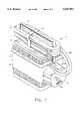
- FIG. 1is a perspective view illustrating the cooler, the pump housing, and the tube assembly of the cold therapy system of the present invention.
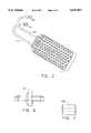
- FIG. 2is a plan view illustrating an exemplary pad for use with the cold therapy system of the present invention.
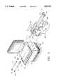
- FIG. 3is a fragmentary, exploded, perspective view of the cold therapy system of the present invention.
- FIG. 4is a fragmentary, exploded, perspective view illustrating the pump, the pump housing, and the control circuit board and switch of the present invention.
- FIG. 5is a fragmentary elevational view of the tube assembly of the present invention.
- FIG. 6is an elevational view of an exemplary check valve used in the output line of the present invention.
- FIG. 7is an elevational view of an exemplary orifice inserted in the return line of the present invention.
- FIG. 8is a schematic diagram of the electronics that drive the pump motor of the present invention.
- FIG. 9is a timing diagram depicting the output pulses of the timer circuits shown at FIG. 8.
- FIG. 1the overall cold therapy system of the present invention is generally indicated at 1.
- the systemcomprises a portable cooler 2 which constitutes a reservoir for water and ice (not shown in FIG. 1).
- the cooler 2has an exterior housing 3 affixed to one of its ends.
- the housing 3contains a pump 4 and a pump control means 5 (see FIG. 4).
- the pump and reservoirare connected to a cooling pad 7 (shown in FIG. 2) by a delivery and return tube assembly, generally indicated at 6.
- the cooling padmay be placed against or wrapped about that part of the user requiring cold therapy.
- the cooler 2may be any appropriate conventional cooler having an insulative body 8 and an insulative lid 9. While it may be a separate element, the lid 9 is preferably hinged to the cooler body 8, and preferably makes a reasonably good sealing closure with the open top of body 8 so that the insulative qualities of the cooler are not compromised.
- the cooler 2may have a bail-type handle 10, as is well known in the art.
- An example of a portable insulative cooler suitable for this purposeis manufactured by Gott Corporation of Winfield, Kans., under the model designation 1910.
- An end wall 19 of the cooler body 8is provided with a pair of bores 11 and 12 extending therethrough.
- a length of plastic tubing, such as PVC tubingis shown at 13 and extends through the bore 11.
- the bore 11is provided with a resilient grommet 14 forming a seal between the inside surface of bore 11 and the exterior surface of tube 13.
- That part of tube 13 which extends exteriorly of cooler body 8is provided with a conventional elbow connector 15.
- the structure just describedcomprises the outlet of reservoir body 8.
- the free end of tube 13, located within the reservoir body 8,is provided with a coiled spring-like strainer 16.
- Such strainersare well known in the art.
- the strainer 16prevents ice chips or crystals from passing through the reservoir outlet.
- the pump 4includes, as a part thereof, a single-speed motor 20.
- the pumphas a tubular inlet port (not shown) and a tubular outlet port 22. It will be understood that the inlet port is substantially identical to outlet port 22.
- Outlet port 22is connected by means of a short piece of PVC tubing 23, or the like, to a connector elbow 24.
- the inlet of pump 4is similarly connected by a short piece of PVC tubing 25, or the like, to the connector elbow 15 of the reservoir outlet. While not necessarily intended to be limiting, in an exemplary embodiment of the cold therapy system of the present system, all tubing used had an internal diameter of 1/4 inch.
- the pump 4had tubular inlet and outlet members having an outside diameter of 3/8 inch.
- the PVC tube segments 23 and 25may be stretched to enable connection between the 3/8 inch pump inlet and outlet elements and the 1/4 inch elbow connectors 24 and 15.
- standard 1/4 inch internal diameter PVC tubingmay be used throughout, without stretching.
- the outlet elbow connector 24 of pump 4is connected to a delivery tube 27.
- Delivery tube 27passes through a perforation 28 in pump housing 3.
- the delivery tube 27is provided with a check valve 27a, the purpose of which will be apparent hereinafter.
- a return tube 29passes through a perforation 30 in pump housing 3.
- Return tube 29is connected to reservoir inlet tube 17 by a conventional tube connector 17a.
- the end of return tube 29, near connector 17ais provided with an orifice 29a, or other appropriate restrictive means, to be further described hereinafter.
- the pump 4is preferably a single-speed, positive displacement pump, easy to prime. Excellent results have been achieved utilizing a 12 Volt DC pump manufactured by Shurflo, of Santa Anna, Calif. and having the Model No. 100-000-22.
- the pump 4is capable of providing up to about 32 gallons per hour (32 gph) of liquid flow.
- the pump-control circuitwhen combined with the pulse-width modulating control circuit of the present invention, will provide selectable outputs to drive the pump at flow rates ranging from about 0.8 gallons per hour (0.8 gph) to about 4 gallons per hour (4 gph) without the usual difficulties encountered when running such a pump in a normal non-intermittent fashion which would require an extremely slow pump actuation rate to produce such low flow rates.
- the pump 4has wrapped thereabout a piece 31 of foamed material.
- the foamed material 31serves several purposes. First of all, it separates the pump 4 from pump housing 3 and the adjacent end 19 of cooler body 8. As a consequence, the pump 4 is essentially free floating within pump housing 3 tending to reduce noise and vibration. Foamed material 31 also acts as an insulator for both heat and noise from the pump.
- the pumpis supported within pump housing 3 by foamed material 31 and the connections to its inlet and outlet ports.
- the pump control means 5comprises a circuit board 32 including a four position manual switch 33.
- the pump control means 5will be described in detail hereinafter.
- the switch portion 33 of the pump control means 5is provided with lateral flanges 33a and 33b which are appropriately affixed to the inside front surface of pump housing 3 by blind rivets 33c or other appropriate fastening means.
- the pump housing 3is provided with a transverse slot 33d through which the manual actuator of switch 33 extends.
- a cover 34 of flexible, waterproof materialis provided to protect the control means 5 from condensation or leakage from the pump.
- the cover 34has a first segment 34a provided with a pressure sensitive adhesive so that it can be adhered to an inside surface of housing 3.
- the coverhas a second segment 34b which overlies and extends rearwardly of the control means 5, when the control means is in its mounted position.
- the protective coverhas a segment 34c which extends downwardly across the face of the printed circuit board of control means 5.
- the insulative foam material 31, wrapped about pump 4, and its motor 20is provided with a panel 31a of pressure sensitive adhesive material.
- This adhesive material 31ais adapted to be adhered to an inside surface of housing 3, when the switch 33, control means 5, protective cover 34 and the pump 4, motor 20 and foam wrap 31 are all positioned within housing 3.
- the motor 20has a connector 20a adapted to be engaged in a connector 5a on the printed circuit board of pump control means 5. In this way, the output of the control means 5 is connected to the pump motor 20 to run the motor in any selected one of a number of intermittent modes, as will be set forth more fully hereinafter.
- the pump housingis mounted on the end 19 of the cooler body 8 by a plurality of self-tapping screws some of which are shown at 35 in FIG. 3.
- the motor 20 of pump 4constitutes a 12 Volt DC motor, as indicated above, and is connected to a source of power through the pump control means 5.
- the power sourcemay be a battery, or it may be a 12-volt power supply, as shown at 36 in FIG. 3.
- Power supply 36may be connected to any conventional household outlet, or the like.
- Power supply 36has an electrical cord 36a extending therefrom. The free end of cord 36a is provided with a jack (not shown) receivable within a socket (not shown) in the bottom surface of pump housing 3. The socket is appropriately connected to the pump control means 5.
- indiciaon the front face of the pump housing to indicate the position of the manual actuator of switch 33.
- indiciais suggested at 39 in FIGS. 1 and 4.
- the indiciamay be color coded and may be provided with legends reading from left to right in FIGS. 1 and 4 as follows: “STOP”, “HIGH”, “MEDIUM”, and “LOW”. Alternatively, they may read from left to right as follows: “STOP”, “COLDEST”, “COLD”, and "COOL".
- outlet elbow 24 of pump 4is connected to a delivery tube 27 which extends through perforation 28 in pump housing 3.
- a return tube 29extends through a perforation 30 in the pump housing 3 and is connected to the inlet tube 17 of reservoir body 8 by connector 17a.
- Delivery and return tubes 27 and 29constitute the tube assembly 6, and are best shown in FIG. 5.
- the delivery and return tubes 27 and 29comprised PVC tubing having a 1/4 inch internal diameter.
- delivery and return tubes 27 and 29are provided respectively with female quick disconnect tube couplings 40 and 41, respectively.
- the female couplings 40 and 41are in-line couplings preferably of the type having shut-off means. Preferably, they are provided with shrouded release buttons to prevent accidental disconnects.
- Female couplings of this typeare available, for example, from Colder Products Company of St. Paul, Minn., having a part number PLCD 170-04.
- the delivery and return tubes 27 and 29are provided substantially throughout their length with a foam tube insulation covering 42.
- the foam tube insulation 42comprises two tubular members having an inside diameter to just nicely receive the delivery and return tubes 27 and 29 and which are joined together by a web located therebetween, so that the foam tube insulation comprises an integral, one-piece structure accommodating both the delivery and return tubes 27 and 29.
- Near its rearward end the foam tube insulation 42is split into two separate end portions 43 and 44 so that they can enter perforations 28 and 30 of pump housing 3. This is shown in FIGS. 1 and 3.
- the foam tube insulation end portion 43 surrounding delivery tube 27extends substantially to the joinder of delivery tube 27 to output elbow 24 of pump 4.
- the foam tube insulation end portion 44 surrounding return tube 29extends substantially to the point where return tube 29 is engaged by connector 17a.
- the foam tube insulation 42is again split into two separate end portions 45 and 46.
- End portion 45surrounding delivery tube 27, extends to the female coupling 40.
- End 46terminates short of female coupling 41, exposing a length of return tube 29.
- the exposed portion of return tube 29contains a liquid crystal temperature indicator shown at 47, or other appropriate temperature indicator.
- Temperature indicator 47monitors and displays the temperature of the water returning from pad 7 to reservoir 8.
- Liquid crystal in-line temperature indicatorsare available, for example, from Hallcrest of Glenview, Ill. The liquid temperature indicator 47 is held in place within return tube 29 by frictional engagement between temperature indicator 47 and the inside surface of return tube 29.
- Insulative member 48has an internal diameter of such size as to be slidable on foam tube insulation end portion 46 between a retracted position wherein it completely exposes temperature indicator 47 (as shown in FIG. 5), and a position wherein the forward end of insulative member 48 contacts female coupling 41, while the rearward end of insulative member 48 slightly overlaps the forwardmost end of foam tube insulation end portion 46.
- the insulative member 48may be used to cover that portion of return tube 29 containing temperature indicator 47 between readings thereof.
- the temperature indicator 47 and its slidable insulative member 48could have been provided in association with delivery tube 27, if desired.
- Storage strap 49has a portion 49a which extends about tube assembly 6.
- Storage strap 49has a laterally extending portion 49b.
- One side of storage strap portion 49bhas affixed thereto one part of a hook and loop tape assembly, as indicated at 50 in FIG. 5.
- the other side of the portion 49b of storage strap 49has affixed thereto the other part of the hook and loop assembly, as indicated at 51 in FIG. 4.
- the storage strap 49enables the tube assembly 6 to be coiled and maintained in a coiled position.
- the tube assembly 6is coiled about the cooler handle 10 and is maintained in this position by storage strap 49, as shown in FIG. 1.
- Cooling pad 7is conventional and may be of any appropriate size or shape.
- the cooling pad 7is normally made up of a pair of compliant plastic plies joined together so as to form a tortuous path for the chilled water entering and leaving the pad.
- the padis provided with a delivery tube 52 and a return tube 53.
- the delivery and return tubes 52 and 53may comprise 1/4 inch PVC tubing.
- One end of each of delivery and return tubes 52 and 53is attached to cooling pad 7.
- the other end of each of delivery and return tubes 52 and 53are provided with straight through male couplings adapted to cooperate with female couplings 40 and 41 (see FIG. 5). Such straight through male couplers are available, for example, from Colder Products Company of St.
- FIG. 8is a schematic diagram of the electronics of the present invention (generally designated by the index numeral 60) which are mounted on the printed circuit board of pump control means 5, and which are used to drive the pump motor 20.
- the power inputis a 12 Volt DC power supply provided by the adapter 36.
- This 12 Volt DC power supplyis fed into a voltage regulator 61, which has a regulated output voltage of +8 Volts DC, which is used throughout the circuit of the electronics 60.
- Selector switch 33can be used to stop the output pulses from timer 62 when its "STOP" position, (position 1 in FIG. 8) is selected. In this mode of operation, the "Reset" inputs of both timer chips 62 and 63 are set to DC Common, which essentially is 0 volts.
- timer 63When selector switch 33 is in any of its operating positions (i.e., in a position other than the "1" STOP position), timer 63 will output a continuous pulse train at approximately 2 kHz, and the duty cycle of each period of this 2 kHz pulse train will be approximately 25%.
- the waveform of this pulse train with respect to the time domain of the output pulses from timer 62is a very dense set of constant pulses, depicted by the waveform timing diagram 64, in which the pulses are so close to one another that they really cannot be drawn accurately on a chart at this scale.
- the pulse traincan be more readily discerned from the timing diagram 65 which shows a 25% duty cycle pulse train, in which the period of each pulse is about 0.5 msec.
- the ON-timeis about 0.125 msec.
- the OFF-timeis about 0.375 msec.
- Timer chip 63has its output connected through resistor R11 to the output transistor T1.
- the output of timer 62is also connected to output transistor T1 through a diode D6.
- pump motor 20When selector switch 33 is in its position "4" COLD position, pump motor 20 will be caused to operate at an effective duty cycle of about 2.77% (1/9 ⁇ 1/4) thereby driving the pump at about 0.8 GPH. It will be understood that motor 20 always runs at a constant speed during those time intervals that an output pulse from timer 62 is at its logic 1 ON-state.
- the primary effect of the electronic signal switched by output transistor T1is to further reduce the pumping capacity of the cold therapy system without attempting to force motor 20 to rotate more slowly (which would increase the motor's cost significantly).
- FIG. 1As a first step, the user releases storage strap 49 and uncoils tubing assembly 6.
- the female and male couplings 40 and 54 of delivery tubes 27 and 52are joined together.
- the female coupling 41 and male coupling 55 of return tubes 29 and 53are also joined together so that the pad 7 is properly connected to the system.
- the cooler handle 10With the tube assembly 6 removed from cooler 2, the cooler handle 10 can be lowered as shown in FIG. 3 and the cooler lid 9 can be pivoted to its open position. At this stage, the reservoir 8 is filled with water and ice. The lid 9 of reservoir body 8 is thereafter closed. Care must be taken to introduce enough water that outlet tube 13, connected to the inlet of pump 4, is submerged during operation.
- timer 62with more than three modes of operation.
- a three mode systemhas been found to be sufficient for most purposes.
Landscapes
- Health & Medical Sciences (AREA)
- Life Sciences & Earth Sciences (AREA)
- Veterinary Medicine (AREA)
- Public Health (AREA)
- Engineering & Computer Science (AREA)
- General Health & Medical Sciences (AREA)
- Animal Behavior & Ethology (AREA)
- Pain & Pain Management (AREA)
- Rehabilitation Therapy (AREA)
- Physical Education & Sports Medicine (AREA)
- Epidemiology (AREA)
- Power Engineering (AREA)
- Physics & Mathematics (AREA)
- Thermal Sciences (AREA)
- Biomedical Technology (AREA)
- Heart & Thoracic Surgery (AREA)
- Vascular Medicine (AREA)
- Thermotherapy And Cooling Therapy Devices (AREA)
Abstract
Description
Claims (18)
Priority Applications (1)
| Application Number | Priority Date | Filing Date | Title |
|---|---|---|---|
| US08/392,036US5647051A (en) | 1995-02-22 | 1995-02-22 | Cold therapy system with intermittent fluid pumping for temperature control |
Applications Claiming Priority (1)
| Application Number | Priority Date | Filing Date | Title |
|---|---|---|---|
| US08/392,036US5647051A (en) | 1995-02-22 | 1995-02-22 | Cold therapy system with intermittent fluid pumping for temperature control |
Publications (1)
| Publication Number | Publication Date |
|---|---|
| US5647051Atrue US5647051A (en) | 1997-07-08 |
Family
ID=23548994
Family Applications (1)
| Application Number | Title | Priority Date | Filing Date |
|---|---|---|---|
| US08/392,036Expired - LifetimeUS5647051A (en) | 1995-02-22 | 1995-02-22 | Cold therapy system with intermittent fluid pumping for temperature control |
Country Status (1)
| Country | Link |
|---|---|
| US (1) | US5647051A (en) |
Cited By (103)
| Publication number | Priority date | Publication date | Assignee | Title |
|---|---|---|---|---|
| US6096068A (en)* | 1998-01-23 | 2000-08-01 | Innercool Therapies, Inc. | Selective organ cooling catheter and method of using the same |
| US6149677A (en)* | 1998-03-31 | 2000-11-21 | Innercool Therapies, Inc. | Circulating fluid hypothermia method |
| USD437417S1 (en) | 1999-12-13 | 2001-02-06 | Deroyal Industries, Inc. | Liquid container for medical cold therapy treatment |
| US6224624B1 (en) | 1998-03-24 | 2001-05-01 | Innercool Therapies, Inc. | Selective organ cooling apparatus and method |
| US6235048B1 (en) | 1998-01-23 | 2001-05-22 | Innercool Therapies, Inc. | Selective organ hypothermia method and apparatus |
| US6238428B1 (en) | 1998-01-23 | 2001-05-29 | Innercool Therapies, Inc. | Selective organ cooling apparatus and method employing turbulence-inducing element with curved terminations |
| US6238427B1 (en) | 1999-03-30 | 2001-05-29 | John G. Matta | Therapeutic heat transfer pads |
| US6245095B1 (en) | 1998-03-24 | 2001-06-12 | Innercool Therapies, Inc. | Method and apparatus for location and temperature specific drug action such as thrombolysis |
| US6251129B1 (en) | 1998-03-24 | 2001-06-26 | Innercool Therapies, Inc. | Method for low temperature thrombolysis and low temperature thrombolytic agent with selective organ temperature control |
| US6251130B1 (en) | 1998-03-24 | 2001-06-26 | Innercool Therapies, Inc. | Device for applications of selective organ cooling |
| US6254626B1 (en) | 1998-03-24 | 2001-07-03 | Innercool Therapies, Inc. | Articulation device for selective organ cooling apparatus |
| US6261312B1 (en) | 1998-06-23 | 2001-07-17 | Innercool Therapies, Inc. | Inflatable catheter for selective organ heating and cooling and method of using the same |
| US6312452B1 (en) | 1998-01-23 | 2001-11-06 | Innercool Therapies, Inc. | Selective organ cooling catheter with guidewire apparatus and temperature-monitoring device |
| US6325818B1 (en) | 1999-10-07 | 2001-12-04 | Innercool Therapies, Inc. | Inflatable cooling apparatus for selective organ hypothermia |
| US6464716B1 (en) | 1998-01-23 | 2002-10-15 | Innercool Therapies, Inc. | Selective organ cooling apparatus and method |
| US6471717B1 (en) | 1998-03-24 | 2002-10-29 | Innercool Therapies, Inc. | Selective organ cooling apparatus and method |
| US6491716B2 (en) | 1998-03-24 | 2002-12-10 | Innercool Therapies, Inc. | Method and device for applications of selective organ cooling |
| US6491039B1 (en) | 1998-01-23 | 2002-12-10 | Innercool Therapies, Inc. | Medical procedure |
| US6537244B2 (en) | 1999-01-19 | 2003-03-25 | Assistive Technology Products, Inc. | Methods and apparatus for delivering fluids |
| US6551349B2 (en) | 1998-03-24 | 2003-04-22 | Innercool Therapies, Inc. | Selective organ cooling apparatus |
| US6551348B1 (en) | 2001-01-26 | 2003-04-22 | Deroyal Industries, Inc. | Temperature controlled fluid therapy system |
| US6558412B2 (en) | 1998-01-23 | 2003-05-06 | Innercool Therapies, Inc. | Selective organ hypothermia method and apparatus |
| US6576001B2 (en) | 2000-03-03 | 2003-06-10 | Innercool Therapies, Inc. | Lumen design for catheter |
| US6576002B2 (en) | 1998-03-24 | 2003-06-10 | Innercool Therapies, Inc. | Isolated selective organ cooling method and apparatus |
| US6585752B2 (en) | 1998-06-23 | 2003-07-01 | Innercool Therapies, Inc. | Fever regulation method and apparatus |
| US6599312B2 (en) | 1998-03-24 | 2003-07-29 | Innercool Therapies, Inc. | Isolated selective organ cooling apparatus |
| US6602276B2 (en) | 1998-03-31 | 2003-08-05 | Innercool Therapies, Inc. | Method and device for performing cooling- or cryo-therapies for, e.g., angioplasty with reduced restenosis or pulmonary vein cell necrosis to inhibit atrial fibrillation |
| US6660028B2 (en) | 2000-06-02 | 2003-12-09 | Innercool Therapies, Inc. | Method for determining the effective thermal mass of a body or organ using a cooling catheter |
| US6685732B2 (en) | 1998-03-31 | 2004-02-03 | Innercool Therapies, Inc. | Method and device for performing cooling- or cryo-therapies for, e.g., angioplasty with reduced restenosis or pulmonary vein cell necrosis to inhibit atrial fibrillation employing microporous balloon |
| US20040068310A1 (en)* | 2002-10-08 | 2004-04-08 | Howard Edelman | Therapy pad |
| US6719779B2 (en) | 2000-11-07 | 2004-04-13 | Innercool Therapies, Inc. | Circulation set for temperature-controlled catheter and method of using the same |
| US6726708B2 (en) | 2000-06-14 | 2004-04-27 | Innercool Therapies, Inc. | Therapeutic heating and cooling via temperature management of a colon-inserted balloon |
| US20040220647A1 (en)* | 2003-04-30 | 2004-11-04 | Alsius Corporation | Intravascular heat exchange catheter with insulated coolant tubes |
| US6830581B2 (en) | 1999-02-09 | 2004-12-14 | Innercool Therspies, Inc. | Method and device for patient temperature control employing optimized rewarming |
| US6843800B1 (en) | 1998-01-23 | 2005-01-18 | Innercool Therapies, Inc. | Patient temperature regulation method and apparatus |
| US6869440B2 (en) | 1999-02-09 | 2005-03-22 | Innercool Therapies, Inc. | Method and apparatus for patient temperature control employing administration of anti-shivering agents |
| US20050092009A1 (en)* | 2003-11-01 | 2005-05-05 | Thurman Timothy T. | Air conditioner pad and water recycling tank |
| US6905494B2 (en) | 1998-03-31 | 2005-06-14 | Innercool Therapies, Inc. | Method and device for performing cooling- or cryo-therapies for, e.g., angioplasty with reduced restenosis or pulmonary vein cell necrosis to inhibit atrial fibrillation employing tissue protection |
| US6991645B2 (en) | 1998-01-23 | 2006-01-31 | Innercool Therapies, Inc. | Patient temperature regulation method and apparatus |
| US7001378B2 (en) | 1998-03-31 | 2006-02-21 | Innercool Therapies, Inc. | Method and device for performing cooling or cryo-therapies, for, e.g., angioplasty with reduced restenosis or pulmonary vein cell necrosis to inhibit atrial fibrillation employing tissue protection |
| US20070021809A1 (en)* | 2005-07-22 | 2007-01-25 | Cole Pamela S | Vagina and vulva cooling and heating device |
| DE102005038766A1 (en)* | 2005-08-17 | 2007-03-01 | Erhard Keller | Body parts e.g. skin, cooling device for e.g. humans, has cooling pad that is provided for attaching at body part, where cooling pad connected to cooling device comprises cold pack with connecting pipes |
| US7291144B2 (en) | 1998-03-31 | 2007-11-06 | Innercool Therapies, Inc. | Method and device for performing cooling- or cryo-therapies for, e.g., angioplasty with reduced restenosis or pulmonary vein cell necrosis to inhibit atrial fibrillation |
| US7300453B2 (en) | 2003-02-24 | 2007-11-27 | Innercool Therapies, Inc. | System and method for inducing hypothermia with control and determination of catheter pressure |
| US20080060374A1 (en)* | 2006-09-08 | 2008-03-13 | Adroit Medical Systems, Inc. | Portable coolant system |
| US7371254B2 (en) | 1998-01-23 | 2008-05-13 | Innercool Therapies, Inc. | Medical procedure |
| US7422600B2 (en) | 1999-02-09 | 2008-09-09 | Innercool Therapies, Inc. | Method and apparatus for patient temperature control employing administration of anti-shivering agents |
| US20090250246A1 (en)* | 2008-04-07 | 2009-10-08 | Andrew Yaung | Solder by numbers, a method and system for populating printed circuit boards |
| US7658205B1 (en) | 2002-12-19 | 2010-02-09 | Vitalwear, Inc. | Systems for a fluid circuit coupler |
| US7694693B1 (en) | 2002-10-08 | 2010-04-13 | Vitalwear, Inc. | Mixing valve for a contrast therapy system |
| US20100106229A1 (en)* | 2006-09-08 | 2010-04-29 | Adroit Medical Systems, Inc. | Thermal skull pads for coolant system |
| US7828831B1 (en) | 2004-12-06 | 2010-11-09 | Deroyal Industries, Inc. | Hot and cold fluid therapy system |
| US7857781B2 (en) | 1998-04-21 | 2010-12-28 | Zoll Circulation, Inc. | Indwelling heat exchange catheter and method of using same |
| US20110098610A1 (en)* | 2009-10-26 | 2011-04-28 | Adroit Medical Systems, Inc. | Disposable Portable Therapy Device |
| CN102144948A (en)* | 2011-04-21 | 2011-08-10 | 谭志添 | A control device for wave cold water of a cold therapy instrument |
| US8052628B1 (en) | 2002-10-08 | 2011-11-08 | Vitalwear, Inc. | Spinal column brace for a contrast therapy system |
| US20110282248A1 (en)* | 2010-03-04 | 2011-11-17 | Martin Ruth E | Portable high frequency air pulse delivery device |
| WO2012087828A1 (en)* | 2010-12-20 | 2012-06-28 | Medical Technology Inc. | Cold therapy apparatus using heat exchanger |
| US8216290B2 (en) | 2002-10-08 | 2012-07-10 | Vitalwear, Inc. | Automated temperature contrast and dynamic pressure modules for a hot or cold wrap therapy system |
| US8425579B1 (en) | 2002-10-08 | 2013-04-23 | Vitalwear, Inc. | Therapeutic knee brace for a contrast therapy system |
| US20130130359A1 (en)* | 2008-12-16 | 2013-05-23 | Nico Corporation | System for collecting and preserving tissue cores |
| WO2013138109A1 (en)* | 2012-03-13 | 2013-09-19 | Medical Technology Inc. | Cold therapy systems and methods |
| US20130253494A1 (en)* | 2002-03-15 | 2013-09-26 | The General Hospital Corporation | Systems for removing heat from subcutaneous lipid-rich cells and systems for removing heat from a target tissue mass |
| US20140074198A1 (en)* | 2012-09-12 | 2014-03-13 | Medical Technology Inc. | Cold therapy apparatus having heat exchanging therapy pad |
| US8715330B2 (en) | 2009-10-22 | 2014-05-06 | Coolsystems, Inc. | Temperature and flow control methods in a thermal therapy device |
| US8979777B2 (en) | 2009-10-26 | 2015-03-17 | Adroit Medical Systems, Inc. | Portable cool therapy device |
| US9114055B2 (en) | 2012-03-13 | 2015-08-25 | Cothera Llc | Deep vein thrombosis (“DVT”) and thermal/compression therapy systems, apparatuses and methods |
| US9314368B2 (en) | 2010-01-25 | 2016-04-19 | Zeltiq Aesthetics, Inc. | Home-use applicators for non-invasively removing heat from subcutaneous lipid-rich cells via phase change coolants, and associates devices, systems and methods |
| USD757286S1 (en) | 2014-07-07 | 2016-05-24 | Deroyal Industries, Inc. | Thermal therapy blanket |
| USD757954S1 (en) | 2014-07-07 | 2016-05-31 | Deroyal Industries, Inc. | Thermal therapy blanket |
| US9375345B2 (en) | 2006-09-26 | 2016-06-28 | Zeltiq Aesthetics, Inc. | Cooling device having a plurality of controllable cooling elements to provide a predetermined cooling profile |
| US9408745B2 (en) | 2007-08-21 | 2016-08-09 | Zeltiq Aesthetics, Inc. | Monitoring the cooling of subcutaneous lipid-rich cells, such as the cooling of adipose tissue |
| US9545523B2 (en) | 2013-03-14 | 2017-01-17 | Zeltiq Aesthetics, Inc. | Multi-modality treatment systems, methods and apparatus for altering subcutaneous lipid-rich tissue |
| USD777338S1 (en) | 2014-03-20 | 2017-01-24 | Zeltiq Aesthetics, Inc. | Cryotherapy applicator for cooling tissue |
| US9655770B2 (en) | 2007-07-13 | 2017-05-23 | Zeltiq Aesthetics, Inc. | System for treating lipid-rich regions |
| US9737434B2 (en) | 2008-12-17 | 2017-08-22 | Zeltiq Aestehtics, Inc. | Systems and methods with interrupt/resume capabilities for treating subcutaneous lipid-rich cells |
| US9844460B2 (en) | 2013-03-14 | 2017-12-19 | Zeltiq Aesthetics, Inc. | Treatment systems with fluid mixing systems and fluid-cooled applicators and methods of using the same |
| US9861421B2 (en) | 2014-01-31 | 2018-01-09 | Zeltiq Aesthetics, Inc. | Compositions, treatment systems and methods for improved cooling of lipid-rich tissue |
| US9861520B2 (en) | 2009-04-30 | 2018-01-09 | Zeltiq Aesthetics, Inc. | Device, system and method of removing heat from subcutaneous lipid-rich cells |
| US10092346B2 (en) | 2010-07-20 | 2018-10-09 | Zeltiq Aesthetics, Inc. | Combined modality treatment systems, methods and apparatus for body contouring applications |
| US10383787B2 (en) | 2007-05-18 | 2019-08-20 | Zeltiq Aesthetics, Inc. | Treatment apparatus for removing heat from subcutaneous lipid-rich cells and massaging tissue |
| US10426656B2 (en) | 2016-07-12 | 2019-10-01 | Stryker Corporation | Thermal control system |
| US10524956B2 (en) | 2016-01-07 | 2020-01-07 | Zeltiq Aesthetics, Inc. | Temperature-dependent adhesion between applicator and skin during cooling of tissue |
| US10555831B2 (en) | 2016-05-10 | 2020-02-11 | Zeltiq Aesthetics, Inc. | Hydrogel substances and methods of cryotherapy |
| US10568759B2 (en) | 2014-08-19 | 2020-02-25 | Zeltiq Aesthetics, Inc. | Treatment systems, small volume applicators, and methods for treating submental tissue |
| US10588778B2 (en) | 2016-03-21 | 2020-03-17 | Stryker Corporation | Mobile thermal system |
| US10675176B1 (en) | 2014-03-19 | 2020-06-09 | Zeltiq Aesthetics, Inc. | Treatment systems, devices, and methods for cooling targeted tissue |
| US10682297B2 (en) | 2016-05-10 | 2020-06-16 | Zeltiq Aesthetics, Inc. | Liposomes, emulsions, and methods for cryotherapy |
| US10722395B2 (en) | 2011-01-25 | 2020-07-28 | Zeltiq Aesthetics, Inc. | Devices, application systems and methods with localized heat flux zones for removing heat from subcutaneous lipid-rich cells |
| US10765552B2 (en) | 2016-02-18 | 2020-09-08 | Zeltiq Aesthetics, Inc. | Cooling cup applicators with contoured heads and liner assemblies |
| US10806625B1 (en)* | 2014-12-05 | 2020-10-20 | Vasper Systems, Llc | Apparatus and method for remote pressure control of a fluidic bladder |
| US10935174B2 (en) | 2014-08-19 | 2021-03-02 | Zeltiq Aesthetics, Inc. | Stress relief couplings for cryotherapy apparatuses |
| US10952891B1 (en) | 2014-05-13 | 2021-03-23 | Zeltiq Aesthetics, Inc. | Treatment systems with adjustable gap applicators and methods for cooling tissue |
| US11076879B2 (en) | 2017-04-26 | 2021-08-03 | Zeltiq Aesthetics, Inc. | Shallow surface cryotherapy applicators and related technology |
| US11154418B2 (en) | 2015-10-19 | 2021-10-26 | Zeltiq Aesthetics, Inc. | Vascular treatment systems, cooling devices, and methods for cooling vascular structures |
| US11285037B1 (en) | 2020-08-13 | 2022-03-29 | Evolve Orthopedics LLC | Mobile cold therapy device |
| US11382790B2 (en) | 2016-05-10 | 2022-07-12 | Zeltiq Aesthetics, Inc. | Skin freezing systems for treating acne and skin conditions |
| US11395760B2 (en) | 2006-09-26 | 2022-07-26 | Zeltiq Aesthetics, Inc. | Tissue treatment methods |
| US11446175B2 (en) | 2018-07-31 | 2022-09-20 | Zeltiq Aesthetics, Inc. | Methods, devices, and systems for improving skin characteristics |
| US11590020B2 (en) | 2002-03-15 | 2023-02-28 | The General Hospital Corporation | Methods and devices for selective disruption of fatty tissue by controlled cooling |
| US11622882B1 (en) | 2020-08-13 | 2023-04-11 | Evolve Orthopedics LLC | Mobile cold therapy device |
| US11986421B2 (en) | 2006-09-26 | 2024-05-21 | Zeltiq Aesthetics, Inc. | Cooling devices with flexible sensors |
| US12070411B2 (en) | 2006-04-28 | 2024-08-27 | Zeltiq Aesthetics, Inc. | Cryoprotectant for use with a treatment device for improved cooling of subcutaneous lipid-rich cells |
Citations (13)
| Publication number | Priority date | Publication date | Assignee | Title |
|---|---|---|---|---|
| US1896953A (en)* | 1931-05-18 | 1933-02-07 | Hassell Cecil Starke | Electric ice cap |
| US2726658A (en)* | 1953-04-27 | 1955-12-13 | Donald E Chessey | Therapeutic cooling devices for domestic and hospital use |
| US3918458A (en)* | 1974-10-07 | 1975-11-11 | Howard J Nethery | Process and apparatus for cryostatic pre-operative treatment of gangrenous extremeties |
| US4112943A (en)* | 1975-03-26 | 1978-09-12 | Adams Robbie J | Therapeutic assembly |
| US4459468A (en)* | 1982-04-14 | 1984-07-10 | Bailey David F | Temperature control fluid circulating system |
| US4821354A (en)* | 1988-03-21 | 1989-04-18 | Little Donald E | Portable cooling pool, beach or car seat mat |
| US4960103A (en)* | 1988-06-28 | 1990-10-02 | Urso Charles L | Versatile heater/cooler |
| US5174285A (en)* | 1990-01-08 | 1992-12-29 | Lake Shore Medical Development Partners Ltd. | Localized heat transfer device |
| US5183039A (en)* | 1991-08-23 | 1993-02-02 | Baxter International Inc. | Temperature control device for fluid filled pad |
| US5241958A (en)* | 1991-08-09 | 1993-09-07 | Noeldner David R | Therapeutic whirlpool unit with temperature contrast |
| US5241951A (en)* | 1990-09-05 | 1993-09-07 | Breg, Inc. | Therapeutic nonambient temperature fluid circulation system |
| US5330519A (en)* | 1990-09-05 | 1994-07-19 | Breg, Inc. | Therapeutic nonambient temperature fluid circulation system |
| US5388176A (en)* | 1992-04-06 | 1995-02-07 | Briggs & Stratton Corp. | DC motor speed control system |
- 1995
- 1995-02-22USUS08/392,036patent/US5647051A/ennot_activeExpired - Lifetime
Patent Citations (15)
| Publication number | Priority date | Publication date | Assignee | Title |
|---|---|---|---|---|
| US1896953A (en)* | 1931-05-18 | 1933-02-07 | Hassell Cecil Starke | Electric ice cap |
| US2726658A (en)* | 1953-04-27 | 1955-12-13 | Donald E Chessey | Therapeutic cooling devices for domestic and hospital use |
| US3918458A (en)* | 1974-10-07 | 1975-11-11 | Howard J Nethery | Process and apparatus for cryostatic pre-operative treatment of gangrenous extremeties |
| US4112943A (en)* | 1975-03-26 | 1978-09-12 | Adams Robbie J | Therapeutic assembly |
| US4459468A (en)* | 1982-04-14 | 1984-07-10 | Bailey David F | Temperature control fluid circulating system |
| US4821354A (en)* | 1988-03-21 | 1989-04-18 | Little Donald E | Portable cooling pool, beach or car seat mat |
| US4960103A (en)* | 1988-06-28 | 1990-10-02 | Urso Charles L | Versatile heater/cooler |
| US5174285A (en)* | 1990-01-08 | 1992-12-29 | Lake Shore Medical Development Partners Ltd. | Localized heat transfer device |
| US5241951A (en)* | 1990-09-05 | 1993-09-07 | Breg, Inc. | Therapeutic nonambient temperature fluid circulation system |
| US5330519A (en)* | 1990-09-05 | 1994-07-19 | Breg, Inc. | Therapeutic nonambient temperature fluid circulation system |
| US5330519B1 (en)* | 1990-09-05 | 1998-11-10 | Breg Inc | Therapeutic nonambient temperature fluid circulation system |
| US5241951B1 (en)* | 1990-09-05 | 1999-07-06 | Breg Inc | Therapeutic nonambient temperature fluid circulation system |
| US5241958A (en)* | 1991-08-09 | 1993-09-07 | Noeldner David R | Therapeutic whirlpool unit with temperature contrast |
| US5183039A (en)* | 1991-08-23 | 1993-02-02 | Baxter International Inc. | Temperature control device for fluid filled pad |
| US5388176A (en)* | 1992-04-06 | 1995-02-07 | Briggs & Stratton Corp. | DC motor speed control system |
Non-Patent Citations (6)
| Title |
|---|
| Sales Brochure Aircast Cryo Cuff, Aircast, Incorporated, P.O. Box 709, Summit, New Jersey 07902 0709, 1991.* |
| Sales Brochure Polar Care Cold Therapy Pump, Breg, Inc., 1281 Liberty Way, Vista, CA 92083, 1991.* |
| Sales Brochure Polar Care Cub, Breg, Inc., 1281 Liberty Way, Vista, CA 92083, 1994.* |
| Sales Brochure--Aircast Cryo-Cuff, Aircast, Incorporated, P.O. Box 709, Summit, New Jersey 07902-0709, 1991. |
| Sales Brochure--Polar Care Cold Therapy Pump, Breg, Inc., 1281 Liberty Way, Vista, CA 92083, 1991. |
| Sales Brochure--Polar Care Cub, Breg, Inc., 1281 Liberty Way, Vista, CA 92083, 1994. |
Cited By (179)
| Publication number | Priority date | Publication date | Assignee | Title |
|---|---|---|---|---|
| US20030018375A1 (en)* | 1998-01-23 | 2003-01-23 | Dobak John D. | Selective organ cooling apparatus and method |
| US6676689B2 (en) | 1998-01-23 | 2004-01-13 | Innercool Therapies, Inc. | Inflatable catheter for selective organ heating and cooling and method of using the same |
| US7998182B2 (en) | 1998-01-23 | 2011-08-16 | Innercool Therapies, Inc. | Selective organ cooling apparatus |
| US6755850B2 (en) | 1998-01-23 | 2004-06-29 | Innercool Therapies, Inc. | Selective organ hypothermia method and apparatus |
| US7951183B2 (en) | 1998-01-23 | 2011-05-31 | Innercool Therapies, Inc. | Medical procedure |
| US6235048B1 (en) | 1998-01-23 | 2001-05-22 | Innercool Therapies, Inc. | Selective organ hypothermia method and apparatus |
| US6238428B1 (en) | 1998-01-23 | 2001-05-29 | Innercool Therapies, Inc. | Selective organ cooling apparatus and method employing turbulence-inducing element with curved terminations |
| US7766949B2 (en) | 1998-01-23 | 2010-08-03 | Innercool Therapies, Inc. | Fever regulation method and apparatus |
| US6786218B2 (en) | 1998-01-23 | 2004-09-07 | Innercool Therapies, Inc. | Medical procedure |
| US6843800B1 (en) | 1998-01-23 | 2005-01-18 | Innercool Therapies, Inc. | Patient temperature regulation method and apparatus |
| US6702842B2 (en) | 1998-01-23 | 2004-03-09 | Innercool Therapies, Inc. | Selective organ cooling apparatus and method |
| US6695873B2 (en) | 1998-01-23 | 2004-02-24 | Innercool Therapies, Inc. | Inflatable catheter for selective organ heating and cooling and method of using the same |
| US7651518B2 (en) | 1998-01-23 | 2010-01-26 | Innercool Therapies, Inc. | Inflatable catheter for selective organ heating and cooling and method of using the same |
| US6096068A (en)* | 1998-01-23 | 2000-08-01 | Innercool Therapies, Inc. | Selective organ cooling catheter and method of using the same |
| US6312452B1 (en) | 1998-01-23 | 2001-11-06 | Innercool Therapies, Inc. | Selective organ cooling catheter with guidewire apparatus and temperature-monitoring device |
| US7371254B2 (en) | 1998-01-23 | 2008-05-13 | Innercool Therapies, Inc. | Medical procedure |
| US6464716B1 (en) | 1998-01-23 | 2002-10-15 | Innercool Therapies, Inc. | Selective organ cooling apparatus and method |
| US6468296B1 (en) | 1998-01-23 | 2002-10-22 | Innercool Therapies, Inc. | Method for low temperature thrombolysis and low temperature thrombolytic agent with selective organ temperature control |
| US6692488B2 (en) | 1998-01-23 | 2004-02-17 | Innercool Therapies, Inc. | Apparatus for cell necrosis |
| US6887262B2 (en) | 1998-01-23 | 2005-05-03 | Innercool Therapies, Inc. | Selective organ cooling apparatus and method |
| US6478811B1 (en) | 1998-01-23 | 2002-11-12 | Innercool Therapies, Inc | Method for low temperature thrombolysis and low temperature thrombolytic agent with selective organ temperature control |
| US6905509B2 (en) | 1998-01-23 | 2005-06-14 | Innercool Therapies, Inc. | Selective organ cooling catheter with guidewire apparatus and temperature-monitoring device |
| US6482226B1 (en) | 1998-01-23 | 2002-11-19 | Innercool Therapies, Inc. | Selective organ hypothermia method and apparatus |
| US6676688B2 (en) | 1998-01-23 | 2004-01-13 | Innercool Therapies, Inc. | Method of making selective organ cooling catheter |
| US8163000B2 (en) | 1998-01-23 | 2012-04-24 | Innercool Therapies, Inc. | Selective organ cooling catheter with guidewire apparatus and temperature-monitoring device |
| US6491039B1 (en) | 1998-01-23 | 2002-12-10 | Innercool Therapies, Inc. | Medical procedure |
| US6533804B2 (en) | 1998-01-23 | 2003-03-18 | Innercool Therapies, Inc. | Inflatable catheter for selective organ heating and cooling and method of using the same |
| US7311725B2 (en) | 1998-01-23 | 2007-12-25 | Innercool Therapies, Inc. | Patient temperature regulation method and apparatus |
| US6540771B2 (en) | 1998-01-23 | 2003-04-01 | Innercool Therapies, Inc. | Inflatable catheter for selective organ heating and cooling and method of using the same |
| US6991645B2 (en) | 1998-01-23 | 2006-01-31 | Innercool Therapies, Inc. | Patient temperature regulation method and apparatus |
| US7101386B2 (en) | 1998-01-23 | 2006-09-05 | Innercool Therapies, Inc. | Patient temperature regulation method and apparatus |
| US6558412B2 (en) | 1998-01-23 | 2003-05-06 | Innercool Therapies, Inc. | Selective organ hypothermia method and apparatus |
| US7094253B2 (en) | 1998-01-23 | 2006-08-22 | Innercool Therapies, Inc. | Fever regulation method and apparatus |
| US6648908B2 (en) | 1998-01-23 | 2003-11-18 | Innercool Therapies, Inc. | Inflatable catheter for selective organ heating and cooling and method of using the same |
| US7063718B2 (en) | 1998-01-23 | 2006-06-20 | Innercool Therapies, Inc. | Selective organ hypothermia method and apparatus |
| US7066948B2 (en) | 1998-01-23 | 2006-06-27 | Innercool Therapies, Inc. | Selective organ cooling apparatus and method |
| US6254626B1 (en) | 1998-03-24 | 2001-07-03 | Innercool Therapies, Inc. | Articulation device for selective organ cooling apparatus |
| US6245095B1 (en) | 1998-03-24 | 2001-06-12 | Innercool Therapies, Inc. | Method and apparatus for location and temperature specific drug action such as thrombolysis |
| US6576002B2 (en) | 1998-03-24 | 2003-06-10 | Innercool Therapies, Inc. | Isolated selective organ cooling method and apparatus |
| US6551349B2 (en) | 1998-03-24 | 2003-04-22 | Innercool Therapies, Inc. | Selective organ cooling apparatus |
| US6491716B2 (en) | 1998-03-24 | 2002-12-10 | Innercool Therapies, Inc. | Method and device for applications of selective organ cooling |
| US6599312B2 (en) | 1998-03-24 | 2003-07-29 | Innercool Therapies, Inc. | Isolated selective organ cooling apparatus |
| US6471717B1 (en) | 1998-03-24 | 2002-10-29 | Innercool Therapies, Inc. | Selective organ cooling apparatus and method |
| US6475231B2 (en) | 1998-03-24 | 2002-11-05 | Innercool Therapies, Inc. | Method and device for applications of selective organ cooling |
| US6582455B1 (en) | 1998-03-24 | 2003-06-24 | Innercool Therapies, Inc. | Method and device for applications of selective organ cooling |
| US6740109B2 (en) | 1998-03-24 | 2004-05-25 | Innercool Therapies, Inc. | Isolated selective organ cooling method |
| US6251130B1 (en) | 1998-03-24 | 2001-06-26 | Innercool Therapies, Inc. | Device for applications of selective organ cooling |
| US6251129B1 (en) | 1998-03-24 | 2001-06-26 | Innercool Therapies, Inc. | Method for low temperature thrombolysis and low temperature thrombolytic agent with selective organ temperature control |
| US6478812B2 (en) | 1998-03-24 | 2002-11-12 | Innercool Therapies, Inc. | Method and device for applications of selective organ cooling |
| US6224624B1 (en) | 1998-03-24 | 2001-05-01 | Innercool Therapies, Inc. | Selective organ cooling apparatus and method |
| US20080300585A1 (en)* | 1998-03-31 | 2008-12-04 | Innercool Therapies, Inc. | Method and device for performing cooling-or cryo-therapies for, e.g., angioplasty with reduced restenosis or pulmonary vein cell necrosis to inhibit atrial fibrillation |
| US6231595B1 (en) | 1998-03-31 | 2001-05-15 | Innercool Therapies, Inc. | Circulating fluid hypothermia method and apparatus |
| US7449018B2 (en) | 1998-03-31 | 2008-11-11 | Innercool Therapies, Inc. | Method and device for performing cooling- or cryo-therapies for, e.g., angioplasty with reduced restenosis or pulmonary vein cell necrosis to inhibit atrial fibrillation employing microporous balloon |
| US7291144B2 (en) | 1998-03-31 | 2007-11-06 | Innercool Therapies, Inc. | Method and device for performing cooling- or cryo-therapies for, e.g., angioplasty with reduced restenosis or pulmonary vein cell necrosis to inhibit atrial fibrillation |
| US7288089B2 (en) | 1998-03-31 | 2007-10-30 | Innercool Therapies, Inc. | Method and device for performing cooling- or cryo-therapies for, e.g., angioplasty with reduced restenosis or pulmonary vein cell necrosis to inhibit atrial fibrillation employing tissue protection |
| US20040087934A1 (en)* | 1998-03-31 | 2004-05-06 | Innercool Therapies, Inc. | Method and device for performing cooling- or cryo-therapies for, E.G., angioplasty with reduced restenosis or pulmonary vein cell necrosis to inhibit atrial fibrillation |
| US6818011B2 (en) | 1998-03-31 | 2004-11-16 | Innercool Therapies, Inc. | Circulating fluid hypothermia method and apparatus |
| US20010007951A1 (en)* | 1998-03-31 | 2001-07-12 | Innercool Therapies, Inc | Circulating fluid hypothermia method and apparatus |
| US6149677A (en)* | 1998-03-31 | 2000-11-21 | Innercool Therapies, Inc. | Circulating fluid hypothermia method |
| US8043351B2 (en) | 1998-03-31 | 2011-10-25 | Innercool Therapies, Inc. | Method and device for performing cooling- or cryo-therapies for, e.g., angioplasty with reduced restenosis or pulmonary vein cell necrosis to inhibit atrial fibrillation employing tissue protection |
| US6685732B2 (en) | 1998-03-31 | 2004-02-03 | Innercool Therapies, Inc. | Method and device for performing cooling- or cryo-therapies for, e.g., angioplasty with reduced restenosis or pulmonary vein cell necrosis to inhibit atrial fibrillation employing microporous balloon |
| US8157794B2 (en) | 1998-03-31 | 2012-04-17 | Innercool Therapies, Inc. | Method and device for performing cooling-or cryo-therapies for, e.g., angioplasty with reduced restenosis or pulmonary vein cell necrosis to inhibit atrial fibrillation |
| US6905494B2 (en) | 1998-03-31 | 2005-06-14 | Innercool Therapies, Inc. | Method and device for performing cooling- or cryo-therapies for, e.g., angioplasty with reduced restenosis or pulmonary vein cell necrosis to inhibit atrial fibrillation employing tissue protection |
| US6602276B2 (en) | 1998-03-31 | 2003-08-05 | Innercool Therapies, Inc. | Method and device for performing cooling- or cryo-therapies for, e.g., angioplasty with reduced restenosis or pulmonary vein cell necrosis to inhibit atrial fibrillation |
| US8043283B2 (en) | 1998-03-31 | 2011-10-25 | Innercool Therapies, Inc. | Method and device for performing cooling- or cryo-therapies for, e.g., angioplasty with reduced restenosis or pulmonary vein cell necrosis to inhibit atrial fibrillation |
| US7001378B2 (en) | 1998-03-31 | 2006-02-21 | Innercool Therapies, Inc. | Method and device for performing cooling or cryo-therapies, for, e.g., angioplasty with reduced restenosis or pulmonary vein cell necrosis to inhibit atrial fibrillation employing tissue protection |
| US7857781B2 (en) | 1998-04-21 | 2010-12-28 | Zoll Circulation, Inc. | Indwelling heat exchange catheter and method of using same |
| US6261312B1 (en) | 1998-06-23 | 2001-07-17 | Innercool Therapies, Inc. | Inflatable catheter for selective organ heating and cooling and method of using the same |
| US7018399B2 (en) | 1998-06-23 | 2006-03-28 | Innercool Therapies, Inc. | Method of making selective organ cooling catheter |
| US6585752B2 (en) | 1998-06-23 | 2003-07-01 | Innercool Therapies, Inc. | Fever regulation method and apparatus |
| US6752779B2 (en) | 1999-01-19 | 2004-06-22 | Assistive Technology Products, Inc. | Methods and apparatus for delivering fluids |
| US6537244B2 (en) | 1999-01-19 | 2003-03-25 | Assistive Technology Products, Inc. | Methods and apparatus for delivering fluids |
| US7351254B2 (en) | 1999-02-09 | 2008-04-01 | Innercool Therapies, Inc. | Method and device for patient temperature control employing optimized rewarming |
| US6869440B2 (en) | 1999-02-09 | 2005-03-22 | Innercool Therapies, Inc. | Method and apparatus for patient temperature control employing administration of anti-shivering agents |
| US7189254B2 (en) | 1999-02-09 | 2007-03-13 | Innercool Therapies, Inc. | Method and device for patient temperature control employing optimized rewarming |
| US6830581B2 (en) | 1999-02-09 | 2004-12-14 | Innercool Therspies, Inc. | Method and device for patient temperature control employing optimized rewarming |
| US7422600B2 (en) | 1999-02-09 | 2008-09-09 | Innercool Therapies, Inc. | Method and apparatus for patient temperature control employing administration of anti-shivering agents |
| US6238427B1 (en) | 1999-03-30 | 2001-05-29 | John G. Matta | Therapeutic heat transfer pads |
| US6676690B2 (en) | 1999-10-07 | 2004-01-13 | Innercool Therapies, Inc. | Inflatable heat transfer apparatus |
| US7052508B2 (en) | 1999-10-07 | 2006-05-30 | Innercool Therapies, Inc. | Inflatable heat transfer apparatus |
| US6325818B1 (en) | 1999-10-07 | 2001-12-04 | Innercool Therapies, Inc. | Inflatable cooling apparatus for selective organ hypothermia |
| USD437417S1 (en) | 1999-12-13 | 2001-02-06 | Deroyal Industries, Inc. | Liquid container for medical cold therapy treatment |
| US6576001B2 (en) | 2000-03-03 | 2003-06-10 | Innercool Therapies, Inc. | Lumen design for catheter |
| US6660028B2 (en) | 2000-06-02 | 2003-12-09 | Innercool Therapies, Inc. | Method for determining the effective thermal mass of a body or organ using a cooling catheter |
| US7211105B2 (en) | 2000-06-02 | 2007-05-01 | Innercool Therapias, Inc. | Method for determining the effective thermal mass of a body or organ using a cooling catheter |
| US6726708B2 (en) | 2000-06-14 | 2004-04-27 | Innercool Therapies, Inc. | Therapeutic heating and cooling via temperature management of a colon-inserted balloon |
| US7491223B2 (en) | 2000-06-14 | 2009-02-17 | Innercool Therapies, Inc. | Therapeutic heating and cooling via temperature management of a colon-inserted balloon |
| US6719779B2 (en) | 2000-11-07 | 2004-04-13 | Innercool Therapies, Inc. | Circulation set for temperature-controlled catheter and method of using the same |
| US7004960B2 (en) | 2000-11-07 | 2006-02-28 | Innercool Therapies, Inc. | Circulation set for temperature-controlled catheter and method of using the same |
| US6551348B1 (en) | 2001-01-26 | 2003-04-22 | Deroyal Industries, Inc. | Temperature controlled fluid therapy system |
| US20130253494A1 (en)* | 2002-03-15 | 2013-09-26 | The General Hospital Corporation | Systems for removing heat from subcutaneous lipid-rich cells and systems for removing heat from a target tissue mass |
| US11590020B2 (en) | 2002-03-15 | 2023-02-28 | The General Hospital Corporation | Methods and devices for selective disruption of fatty tissue by controlled cooling |
| US7211104B2 (en) | 2002-10-08 | 2007-05-01 | Vital Wear, Inc. | Contrast therapy system and method |
| US7694693B1 (en) | 2002-10-08 | 2010-04-13 | Vitalwear, Inc. | Mixing valve for a contrast therapy system |
| US8425579B1 (en) | 2002-10-08 | 2013-04-23 | Vitalwear, Inc. | Therapeutic knee brace for a contrast therapy system |
| US8216290B2 (en) | 2002-10-08 | 2012-07-10 | Vitalwear, Inc. | Automated temperature contrast and dynamic pressure modules for a hot or cold wrap therapy system |
| US20040068310A1 (en)* | 2002-10-08 | 2004-04-08 | Howard Edelman | Therapy pad |
| US8052628B1 (en) | 2002-10-08 | 2011-11-08 | Vitalwear, Inc. | Spinal column brace for a contrast therapy system |
| US7658205B1 (en) | 2002-12-19 | 2010-02-09 | Vitalwear, Inc. | Systems for a fluid circuit coupler |
| US7300453B2 (en) | 2003-02-24 | 2007-11-27 | Innercool Therapies, Inc. | System and method for inducing hypothermia with control and determination of catheter pressure |
| US7001418B2 (en)* | 2003-04-30 | 2006-02-21 | Alsius Corporation | Intravascular heat exchange catheter with insulated coolant tubes |
| US20040220647A1 (en)* | 2003-04-30 | 2004-11-04 | Alsius Corporation | Intravascular heat exchange catheter with insulated coolant tubes |
| US20050092009A1 (en)* | 2003-11-01 | 2005-05-05 | Thurman Timothy T. | Air conditioner pad and water recycling tank |
| US7828831B1 (en) | 2004-12-06 | 2010-11-09 | Deroyal Industries, Inc. | Hot and cold fluid therapy system |
| US20070021809A1 (en)* | 2005-07-22 | 2007-01-25 | Cole Pamela S | Vagina and vulva cooling and heating device |
| DE102005038766A1 (en)* | 2005-08-17 | 2007-03-01 | Erhard Keller | Body parts e.g. skin, cooling device for e.g. humans, has cooling pad that is provided for attaching at body part, where cooling pad connected to cooling device comprises cold pack with connecting pipes |
| US12070411B2 (en) | 2006-04-28 | 2024-08-27 | Zeltiq Aesthetics, Inc. | Cryoprotectant for use with a treatment device for improved cooling of subcutaneous lipid-rich cells |
| US7640764B2 (en) | 2006-09-08 | 2010-01-05 | Adroit Medical Systems, Inc. | Portable coolant system |
| US20080060374A1 (en)* | 2006-09-08 | 2008-03-13 | Adroit Medical Systems, Inc. | Portable coolant system |
| US20100106229A1 (en)* | 2006-09-08 | 2010-04-29 | Adroit Medical Systems, Inc. | Thermal skull pads for coolant system |
| US11179269B2 (en) | 2006-09-26 | 2021-11-23 | Zeltiq Aesthetics, Inc. | Cooling device having a plurality of controllable cooling elements to provide a predetermined cooling profile |
| US11986421B2 (en) | 2006-09-26 | 2024-05-21 | Zeltiq Aesthetics, Inc. | Cooling devices with flexible sensors |
| US11395760B2 (en) | 2006-09-26 | 2022-07-26 | Zeltiq Aesthetics, Inc. | Tissue treatment methods |
| US10292859B2 (en) | 2006-09-26 | 2019-05-21 | Zeltiq Aesthetics, Inc. | Cooling device having a plurality of controllable cooling elements to provide a predetermined cooling profile |
| US11219549B2 (en) | 2006-09-26 | 2022-01-11 | Zeltiq Aesthetics, Inc. | Cooling device having a plurality of controllable cooling elements to provide a predetermined cooling profile |
| US9375345B2 (en) | 2006-09-26 | 2016-06-28 | Zeltiq Aesthetics, Inc. | Cooling device having a plurality of controllable cooling elements to provide a predetermined cooling profile |
| US10383787B2 (en) | 2007-05-18 | 2019-08-20 | Zeltiq Aesthetics, Inc. | Treatment apparatus for removing heat from subcutaneous lipid-rich cells and massaging tissue |
| US11291606B2 (en) | 2007-05-18 | 2022-04-05 | Zeltiq Aesthetics, Inc. | Treatment apparatus for removing heat from subcutaneous lipid-rich cells and massaging tissue |
| US9655770B2 (en) | 2007-07-13 | 2017-05-23 | Zeltiq Aesthetics, Inc. | System for treating lipid-rich regions |
| US11583438B1 (en) | 2007-08-21 | 2023-02-21 | Zeltiq Aesthetics, Inc. | Monitoring the cooling of subcutaneous lipid-rich cells, such as the cooling of adipose tissue |
| US10675178B2 (en) | 2007-08-21 | 2020-06-09 | Zeltiq Aesthetics, Inc. | Monitoring the cooling of subcutaneous lipid-rich cells, such as the cooling of adipose tissue |
| US9408745B2 (en) | 2007-08-21 | 2016-08-09 | Zeltiq Aesthetics, Inc. | Monitoring the cooling of subcutaneous lipid-rich cells, such as the cooling of adipose tissue |
| US20090250246A1 (en)* | 2008-04-07 | 2009-10-08 | Andrew Yaung | Solder by numbers, a method and system for populating printed circuit boards |
| US9504247B2 (en)* | 2008-12-16 | 2016-11-29 | Nico Corporation | System for collecting and preserving tissue cores |
| US20130130359A1 (en)* | 2008-12-16 | 2013-05-23 | Nico Corporation | System for collecting and preserving tissue cores |
| US9737434B2 (en) | 2008-12-17 | 2017-08-22 | Zeltiq Aestehtics, Inc. | Systems and methods with interrupt/resume capabilities for treating subcutaneous lipid-rich cells |
| US11224536B2 (en) | 2009-04-30 | 2022-01-18 | Zeltiq Aesthetics, Inc. | Device, system and method of removing heat from subcutaneous lipid-rich cells |
| US11452634B2 (en) | 2009-04-30 | 2022-09-27 | Zeltiq Aesthetics, Inc. | Device, system and method of removing heat from subcutaneous lipid-rich cells |
| US9861520B2 (en) | 2009-04-30 | 2018-01-09 | Zeltiq Aesthetics, Inc. | Device, system and method of removing heat from subcutaneous lipid-rich cells |
| US8715330B2 (en) | 2009-10-22 | 2014-05-06 | Coolsystems, Inc. | Temperature and flow control methods in a thermal therapy device |
| US9943437B2 (en) | 2009-10-22 | 2018-04-17 | Coolsystems, Inc. | Temperature and flow control methods in a thermal therapy device |
| US8979777B2 (en) | 2009-10-26 | 2015-03-17 | Adroit Medical Systems, Inc. | Portable cool therapy device |
| US8512263B2 (en) | 2009-10-26 | 2013-08-20 | Adroit Medical Systems, Inc. | Disposable portable therapy device |
| US20110098610A1 (en)* | 2009-10-26 | 2011-04-28 | Adroit Medical Systems, Inc. | Disposable Portable Therapy Device |
| US9314368B2 (en) | 2010-01-25 | 2016-04-19 | Zeltiq Aesthetics, Inc. | Home-use applicators for non-invasively removing heat from subcutaneous lipid-rich cells via phase change coolants, and associates devices, systems and methods |
| US9844461B2 (en) | 2010-01-25 | 2017-12-19 | Zeltiq Aesthetics, Inc. | Home-use applicators for non-invasively removing heat from subcutaneous lipid-rich cells via phase change coolants |
| US20110282248A1 (en)* | 2010-03-04 | 2011-11-17 | Martin Ruth E | Portable high frequency air pulse delivery device |
| US10092346B2 (en) | 2010-07-20 | 2018-10-09 | Zeltiq Aesthetics, Inc. | Combined modality treatment systems, methods and apparatus for body contouring applications |
| CN103338730A (en)* | 2010-12-20 | 2013-10-02 | 医疗技术有限公司 | Cold therapy apparatus using heat exchanger |
| WO2012087828A1 (en)* | 2010-12-20 | 2012-06-28 | Medical Technology Inc. | Cold therapy apparatus using heat exchanger |
| CN103338730B (en)* | 2010-12-20 | 2016-04-27 | 布雷格有限公司 | Use the cold therapy device of heat exchanger |
| US8613762B2 (en) | 2010-12-20 | 2013-12-24 | Medical Technology Inc. | Cold therapy apparatus using heat exchanger |
| US10722395B2 (en) | 2011-01-25 | 2020-07-28 | Zeltiq Aesthetics, Inc. | Devices, application systems and methods with localized heat flux zones for removing heat from subcutaneous lipid-rich cells |
| CN102144948A (en)* | 2011-04-21 | 2011-08-10 | 谭志添 | A control device for wave cold water of a cold therapy instrument |
| US9114055B2 (en) | 2012-03-13 | 2015-08-25 | Cothera Llc | Deep vein thrombosis (“DVT”) and thermal/compression therapy systems, apparatuses and methods |
| US9566187B2 (en) | 2012-03-13 | 2017-02-14 | Breg, Inc. | Cold therapy systems and methods |
| WO2013138109A1 (en)* | 2012-03-13 | 2013-09-19 | Medical Technology Inc. | Cold therapy systems and methods |
| US20140074198A1 (en)* | 2012-09-12 | 2014-03-13 | Medical Technology Inc. | Cold therapy apparatus having heat exchanging therapy pad |
| US9402763B2 (en)* | 2012-09-12 | 2016-08-02 | Breg, Inc. | Cold therapy apparatus having heat exchanging therapy pad |
| US9844460B2 (en) | 2013-03-14 | 2017-12-19 | Zeltiq Aesthetics, Inc. | Treatment systems with fluid mixing systems and fluid-cooled applicators and methods of using the same |
| US9545523B2 (en) | 2013-03-14 | 2017-01-17 | Zeltiq Aesthetics, Inc. | Multi-modality treatment systems, methods and apparatus for altering subcutaneous lipid-rich tissue |
| US10806500B2 (en) | 2014-01-31 | 2020-10-20 | Zeltiq Aesthetics, Inc. | Treatment systems, methods, and apparatuses for improving the appearance of skin and providing other treatments |
| US9861421B2 (en) | 2014-01-31 | 2018-01-09 | Zeltiq Aesthetics, Inc. | Compositions, treatment systems and methods for improved cooling of lipid-rich tissue |
| US10201380B2 (en) | 2014-01-31 | 2019-02-12 | Zeltiq Aesthetics, Inc. | Treatment systems, methods, and apparatuses for improving the appearance of skin and providing other treatments |
| US11819257B2 (en) | 2014-01-31 | 2023-11-21 | Zeltiq Aesthetics, Inc. | Compositions, treatment systems and methods for improved cooling of lipid-rich tissue |
| US10912599B2 (en) | 2014-01-31 | 2021-02-09 | Zeltiq Aesthetics, Inc. | Compositions, treatment systems and methods for improved cooling of lipid-rich tissue |
| US10575890B2 (en) | 2014-01-31 | 2020-03-03 | Zeltiq Aesthetics, Inc. | Treatment systems and methods for affecting glands and other targeted structures |
| US10675176B1 (en) | 2014-03-19 | 2020-06-09 | Zeltiq Aesthetics, Inc. | Treatment systems, devices, and methods for cooling targeted tissue |
| USD777338S1 (en) | 2014-03-20 | 2017-01-24 | Zeltiq Aesthetics, Inc. | Cryotherapy applicator for cooling tissue |
| US10952891B1 (en) | 2014-05-13 | 2021-03-23 | Zeltiq Aesthetics, Inc. | Treatment systems with adjustable gap applicators and methods for cooling tissue |
| USD757286S1 (en) | 2014-07-07 | 2016-05-24 | Deroyal Industries, Inc. | Thermal therapy blanket |
| USD757954S1 (en) | 2014-07-07 | 2016-05-31 | Deroyal Industries, Inc. | Thermal therapy blanket |
| US10935174B2 (en) | 2014-08-19 | 2021-03-02 | Zeltiq Aesthetics, Inc. | Stress relief couplings for cryotherapy apparatuses |
| US10568759B2 (en) | 2014-08-19 | 2020-02-25 | Zeltiq Aesthetics, Inc. | Treatment systems, small volume applicators, and methods for treating submental tissue |
| US10806625B1 (en)* | 2014-12-05 | 2020-10-20 | Vasper Systems, Llc | Apparatus and method for remote pressure control of a fluidic bladder |
| US11154418B2 (en) | 2015-10-19 | 2021-10-26 | Zeltiq Aesthetics, Inc. | Vascular treatment systems, cooling devices, and methods for cooling vascular structures |
| US10524956B2 (en) | 2016-01-07 | 2020-01-07 | Zeltiq Aesthetics, Inc. | Temperature-dependent adhesion between applicator and skin during cooling of tissue |
| US10765552B2 (en) | 2016-02-18 | 2020-09-08 | Zeltiq Aesthetics, Inc. | Cooling cup applicators with contoured heads and liner assemblies |
| US10588778B2 (en) | 2016-03-21 | 2020-03-17 | Stryker Corporation | Mobile thermal system |
| US11382790B2 (en) | 2016-05-10 | 2022-07-12 | Zeltiq Aesthetics, Inc. | Skin freezing systems for treating acne and skin conditions |
| US10682297B2 (en) | 2016-05-10 | 2020-06-16 | Zeltiq Aesthetics, Inc. | Liposomes, emulsions, and methods for cryotherapy |
| US10555831B2 (en) | 2016-05-10 | 2020-02-11 | Zeltiq Aesthetics, Inc. | Hydrogel substances and methods of cryotherapy |
| US10426656B2 (en) | 2016-07-12 | 2019-10-01 | Stryker Corporation | Thermal control system |
| US11076879B2 (en) | 2017-04-26 | 2021-08-03 | Zeltiq Aesthetics, Inc. | Shallow surface cryotherapy applicators and related technology |
| US11446175B2 (en) | 2018-07-31 | 2022-09-20 | Zeltiq Aesthetics, Inc. | Methods, devices, and systems for improving skin characteristics |
| US12102557B2 (en) | 2018-07-31 | 2024-10-01 | Zeltiq Aesthetics, Inc. | Methods, devices, and systems for improving skin characteristics |
| US11285037B1 (en) | 2020-08-13 | 2022-03-29 | Evolve Orthopedics LLC | Mobile cold therapy device |
| US11622882B1 (en) | 2020-08-13 | 2023-04-11 | Evolve Orthopedics LLC | Mobile cold therapy device |
| US12070412B1 (en) | 2020-08-13 | 2024-08-27 | Evolve Orthopedics LLC | Mobile cold therapy device |
Similar Documents
| Publication | Publication Date | Title |
|---|---|---|
| US5647051A (en) | Cold therapy system with intermittent fluid pumping for temperature control | |
| US5476489A (en) | Cold therapy system | |
| US10350108B1 (en) | Heating/cooling therapy system | |
| US6551348B1 (en) | Temperature controlled fluid therapy system | |
| US7640764B2 (en) | Portable coolant system | |
| US5241951A (en) | Therapeutic nonambient temperature fluid circulation system | |
| US20070118194A1 (en) | Non-ambient temperature therapy system with automatic treatment temperature maintenance | |
| US5980561A (en) | Applying thermal therapy to living tissue | |
| US5871526A (en) | Portable temperature control system | |
| US7666215B2 (en) | System and method for determining and controlling core body temperature | |
| US5330519A (en) | Therapeutic nonambient temperature fluid circulation system | |
| CA1155028A (en) | Therapeutic device | |
| CA1158514A (en) | Therapeutic device | |
| US6228048B1 (en) | Colonic irrigation apparatus and method | |
| US4844080A (en) | Ultrasound contact medium dispenser | |
| US4160455A (en) | Heater for heating fluid in a body cavity | |
| US8216290B2 (en) | Automated temperature contrast and dynamic pressure modules for a hot or cold wrap therapy system | |
| US7175649B2 (en) | Method and system for control of a patient's body temperature by way of transluminally insertable heat exchange catheter | |
| US11857491B2 (en) | Integrated cold therapy-compression therapy assembly and associated treatment protocols | |
| US20120179230A1 (en) | Device For Performing Beauty, Physiotherapy and Hydrotherapy Treatment | |
| CA2368243A1 (en) | Central venous line catheter having temperature control system | |
| WO1995010251A1 (en) | Portable temperature control system | |
| WO2002026285A3 (en) | Kit of parts including a central venous line catheter having a temperature control system | |
| US4023561A (en) | Water caloric systems and methods for inducing nystagmus | |
| CN214970426U (en) | Transfusion heating device |
Legal Events
| Date | Code | Title | Description |
|---|---|---|---|
| AS | Assignment | Owner name:SEABROOK MEDICAL SYSTEMS, INC., OHIO Free format text:ASSIGNMENT OF ASSIGNORS INTEREST;ASSIGNOR:NEER, CHARLES S.;REEL/FRAME:007366/0730 Effective date:19950222 | |
| AS | Assignment | Owner name:BRISTOL-MYERS SQUIBB COMPANY, NEW YORK Free format text:ASSIGNMENT OF ASSIGNORS INTEREST;ASSIGNOR:SEABROOK MEDICAL SYSTEMS, INC. (BY TIMOTHY M. WENDT, VICE PRESIDENT);REEL/FRAME:007910/0514 Effective date:19960423 | |
| STCF | Information on status: patent grant | Free format text:PATENTED CASE | |
| AS | Assignment | Owner name:CINCINNATI SUB-ZERO PRODUCTS, INC, OHIO Free format text:ASSIGNMENT OF ASSIGNORS INTEREST;ASSIGNOR:BRISTOL-MYERS SQUIBB COMPANY;REEL/FRAME:009866/0183 Effective date:19980929 | |
| FPAY | Fee payment | Year of fee payment:4 | |
| FPAY | Fee payment | Year of fee payment:8 | |
| AS | Assignment | Owner name:LASALLE BANK NATIONAL ASSOCIATION, ILLINOIS Free format text:SECURITY AGREEMENT;ASSIGNOR:CINCINNATI SUB-ZERO PRODUCTS, INC.;REEL/FRAME:018797/0044 Effective date:20061031 | |
| FPAY | Fee payment | Year of fee payment:12 | |
| AS | Assignment | Owner name:CINCINNATI SUB-ZERO PRODUCTS, INC., OHIO Free format text:RELEASE BY SECURED PARTY;ASSIGNOR:BANK OF AMERICA, N.A., SUCESSOR BY MERGER OR ACQUISITION TO LASALLE BANK, N.A.;REEL/FRAME:022928/0491 Effective date:20090605 |