US5646982A - System and method for message delivery - Google Patents
System and method for message deliveryDownload PDFInfo
- Publication number
- US5646982A US5646982AUS08/366,559US36655994AUS5646982AUS 5646982 AUS5646982 AUS 5646982AUS 36655994 AUS36655994 AUS 36655994AUS 5646982 AUS5646982 AUS 5646982A
- Authority
- US
- United States
- Prior art keywords
- message
- call
- delivery
- response unit
- voice response
- Prior art date
- Legal status (The legal status is an assumption and is not a legal conclusion. Google has not performed a legal analysis and makes no representation as to the accuracy of the status listed.)
- Expired - Lifetime
Links
Images


Classifications
- H—ELECTRICITY
- H04—ELECTRIC COMMUNICATION TECHNIQUE
- H04M—TELEPHONIC COMMUNICATION
- H04M3/00—Automatic or semi-automatic exchanges
- H04M3/42—Systems providing special services or facilities to subscribers
- H04M3/50—Centralised arrangements for answering calls; Centralised arrangements for recording messages for absent or busy subscribers ; Centralised arrangements for recording messages
- H04M3/53—Centralised arrangements for recording incoming messages, i.e. mailbox systems
- H04M3/533—Voice mail systems
- H04M3/53316—Messaging centre selected by message originator
- H—ELECTRICITY
- H04—ELECTRIC COMMUNICATION TECHNIQUE
- H04M—TELEPHONIC COMMUNICATION
- H04M2203/00—Aspects of automatic or semi-automatic exchanges
- H04M2203/20—Aspects of automatic or semi-automatic exchanges related to features of supplementary services
- H04M2203/2016—Call initiation by network rather than by subscriber
Definitions
- the present inventionrelates generally to call processing systems, and more specifically to a system and method for recording, scheduling and delivering messages.
- processor-based systemsWith the growth of processor technology came the application of processor-based systems in the telephone industry. The functionality of call processing systems grew exponentially with the introduction of processor-based systems. One area of expanded functionality is in enhanced calling features. One such feature is voice and data message delivery.
- An early voice messaging system still in use todayis the telephone answering service.
- one or more operatorsare enlisted to handle the telephone traffic of the service's clients.
- the operatorsanswer the clients' incoming calls and take messages and orders for the client or otherwise provide information to the caller.
- Each operatoris positioned at an operator station having several incoming lines. When a call comes in on one of the lines, the operator answers the call.
- the operatorprovides an appropriate greeting to the caller, identifying the service's client to whom the call is placed. The operator can then proceed to take a message for the client, take an order for the client's goods or services, or otherwise provide information to the caller about the client.
- Another message systemprovides voice mailboxes that store messages for the called party.
- the stored messagesare delivered when the called party accesses his or her voice mailbox. While such a system avoids the need for human operator intervention, the flexibility and features provided by voice mailboxes are not much greater than that provided by the average in-home answering machine.
- the present inventionis directed to a system and method for recording, scheduling for delivery, and delivering messages.
- a message delivery serviceis provided that coordinates the recording, scheduling and delivery of messages received from one user and intended for another.
- the message delivery serviceincludes a message delivery system interfaced to a call processing system.
- the message delivery systemincludes a message delivery controller, a scheduler, and data storage area for storing messages to be delivered, message information, and delivery schedule information.
- the message delivery controllerdetermines the delivery schedule and communicates with the call processing system to coordinate message delivery.
- An automated voice response unit in the call processing systeminterfaces with the sending user, stores the message in the message delivery system, and retrieves the message for delivery to the recipient.
- the automated voice response unitWhen a call is received from a first user who is leaving a message for a second user, the automated voice response unit queries the first user for message delivery information and other message options, as well as for the actual message itself.
- the automated voice response unitstores the message in a message database and creates an access record for the message.
- the access recordcan include all relevant information regarding the message such as the destination telephone number, the time at which the message was recorded, message keys identifying data in the message database, and a scheduler ID.
- the access recordis stored in an access database and identified by an access key.
- the messageis scheduled for delivery.
- the usercan request delivery at a specified date and time, or upon the passage of a determined amount of time.
- the useralso can specify the number of retry attempts where delivery is unsuccessful and the amount of time to wait between retry attempts.
- a message delivery systemperforms a time calculation to determine when to start the first delivery attempt.
- the messageis scheduled for delivery and a schedule event is stored in a scheduler database, the schedule event indicating that the delivery of the message is to be initiated at a specified date and time.
- the message delivery systeminforms the network control processor that a message is to be sent.
- the automated voice response unitretrieves the access record for the message and instructs the network control processor to originate a call to the message recipient.
- the automated voice response unitretrieves the message from the message database service and delivers the message to the recipient. Once the message is delivered, it can be deleted from the message database.
- retry attemptscan be made.
- the message delivery systemdetermines whether a retry attempt is to be made, and if so, schedules the attempt. At the scheduled time, the message delivery is attempted again.
- One advantage of the message delivery systemis that it provides for message storage, scheduling and delivery without the need for human operator intervention.
- the entire process of message storage, scheduling and deliveryis fully automated.
- the automated voice response unitanswers the user's call, queries the user for information pertaining to the message and its delivery and scheduling and queries the user for the message itself.
- the automated voice response unitrecords the message and informs the message delivery system that the message is to be scheduled for delivery.
- the systemautomatically initiates a call to the recipient, introduces the message, and delivers the message to the recipient.
- Another advantage of the inventionis that communications to the sending and recipient users are made using automated scripts sent via the automated voice response unit.
- the scriptsprompt the user for required information and provide the user with menus from which input choices can be selected.
- Scriptsalso provide dialogue to the recipient when the message is delivered.
- the scriptscan be customized at the user, subscriber, and/or customer level. Such customization allows the system to provide, for example, carrier unique greetings, customized message handling features, and other custom user interfaces. To accomplish this, scripts can be recorded and played based on call data such as the caller's ID, the caller's carrier ID, the recipient's ID, and other like information.
- DEF recordsprovide instructions to the automated voice response unit on how to process the message recording, scheduling, and delivery.
- the DEF recordscan be customized at the user, subscriber and/or customer level so that different users, or users of different carriers, are provided with different message delivery features.
- Another advantage of the inventionis that it maximizes message storage by allowing different types of data to be stored in the same device using the same message delivery service.
- the message delivery servicedoes not care whether the message to be stored and delivered is a voice message, a data message, a facsimile, or other message type. This provides the further advantage of eliminating machine-dependent recording, storage and delivery.
- FIG. 1is a high-level block diagram illustrating the architecture of a conventional telephone switching configuration.
- FIG. 2is a high-level operational flow diagram illustrating the manner in which a conventional long-distance carrier provides long-distance telephone services to a long-distance carrier customer.
- FIG. 3is a high-level block diagram illustrating a call processing system.
- FIG. 4is a high-level block diagram illustrating the interface of customers and users to the call processing system according to one embodiment of the present invention.
- FIG. 5is a high-level operational flow diagram illustrating the steps involved in placing and completing a call using the call processing system.
- FIG. 6, which comprises FIGS. 7 and 8,is a high-level operational flow diagram illustrating the process that the call processing system uses to process operator-assisted calls.
- FIG. 7is a high-level operational flow diagram illustrating the process that the call processing system uses to process operator-assisted calls.
- FIG. 8which is a continuation of FIG. 7, illustrates a high-level operational flow of the process that the call processing system uses to process operator-assisted calls.
- FIG. 9is a block diagram illustrating a message delivery service according to one embodiment of the invention.
- FIG. 10is a high-level operational flow diagram illustrating the operation of the message delivery service according to one embodiment of the invention.
- FIG. 11is an operational flow diagram illustrating the manner in which the message delivery service stores and schedules messages (i.e. step 1012, FIG. 10).
- FIG. 12, which comprises FIGS. 13, 14 and 15is an operational flow diagram that details a process for storing and recording messages according to one embodiment of the invention.
- FIG. 13is an operational flow diagram that details a process for storing and recording messages according to one embodiment of the invention.
- FIG. 14, which is a continuation of FIG. 13,is an operational flow diagram that details a process for storing and recording messages according to one embodiment of the invention.
- FIG. 15,which is a continuation of FIG. 14, is an operational flow diagram that details a process for storing and recording messages according to one embodiment of the invention.
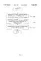
- FIG. 16is a high-level operational flow diagram illustrating a method by which a scheduled message is delivered to a user.
- FIG. 17is an operational flow diagram illustrating the manner in which the message delivery service sets up for message delivery (i.e., step 1608).
- FIG. 18is an operational flow diagram illustrating a method by which the message delivery service retrieves and delivers the message to a user.
- FIG. 19,which comprises FIGS. 20, 21, 22, 23, and 24, is an operational flow diagram illustrating a process of message delivery according to one embodiment of the invention.
- FIG. 20is an operational flow diagram illustrating a process of message delivery according to one embodiment of the invention.
- FIG. 21, which is a continuation of FIG. 20,is an operational flow diagram illustrating a process of message delivery according to one embodiment of the invention.
- FIG. 22, which is a continuation of FIG. 21,is an operational flow diagram illustrating a process of message delivery according to one embodiment of the invention.
- FIG. 23, which is a continuation of FIG. 22,is an operational flow diagram illustrating a process of message delivery according to one embodiment of the invention.
- FIG. 24, which is a continuation of FIG. 22,is an operational flow diagram illustrating a process of message delivery according to one embodiment of the invention.
- FIG. 25is a block diagram illustrating a scheduling information structure used to determine the strategy for message delivery.
- FIG. 26is a diagram illustrating variables used to calculate message delivery time.
- FIG. 27is an operational flow diagram illustrating a process by which the next attempt time calculation is made according to one embodiment of the invention.
- FIG. 28is an operational flow diagram illustrating the steps followed when a retry attempt is scheduled.
- FIG. 29is an operational flow diagram illustrating the process that occurs when a message is not delivered and no retry attempts remain.
- the present inventionis directed toward a system and method for message delivery.
- the messaging systemoperates in the environment of a call processing system.
- two call processing systemsare first described.
- Section 1.1a standard call processing is described.
- Section 1.2describes an enhanced call processing system that utilizes a network control processor (NCP) 304 (illustrated in FIG. 3) to provide enhanced call processing features.
- NCPnetwork control processor
- FIG. 1is a high-level block diagram illustrating the architecture of a conventional telephone switching configuration.
- the configurationincludes a matrix switch 102 and an operator console 108.
- a typical subscriber 114 to a long-distance carrier 112may be a business, another carrier, or an individual user 106.
- Customer 110may, for example, be a business or it may be a carrier that is procuring enhanced services from a competitor long-distance carrier 112.
- Customer 110may have its own customer switch 104 for routing calls between outside trunks and inside lines or instruments.
- Users 106place long-distance calls using long-distance carrier 112.
- the user 106 who places the callis termed an originating user 106A.
- the user 106 to whom the call is placedis termed a terminating user 106B.
- Originating user 106Amay place the call directly with long-distance carrier 112 where originating user 106A is a customer of long-distance carrier 112. Where originating user 106A subscribes to another carrier that is a customer 110 of long-distance carrier 112, the call is muted through customer 110. Where originating user 106A is an end-user at a business that is a customer 110 of long-distance carrier 112 and that has its own switch 104, that originating user's call also gets routed through customer switch 104. In the latter two cases, originating user 106A is deemed a "client" of customer 110.
- Matrix switch 102is provided as a switch to route calls between users 106. A call is routed from originating user 106A to terminating user 106B. Matrix switch 102 typically can route thousands of telephone calls simultaneously.
- An example of matrix switch 102is the commercially-available switch model DMS 250, manufactured by Northern Telecom, Inc. in Richardson, Tex., USA. "DMS" is a registered trademark of Northern Telecom, Inc.
- FIG. 2is a high-level operational flow diagram illustrating the manner in which long-distance carrier 112 provides long-distance telephone services to its subscribers 114.
- FIGS. 1 and 2are now referred to in order to illustrate how long-distance carrier 112 provides direct-dial long-distance service and operator-assisted calling for users 106.
- Long-distance direct dialingis accomplished by dialing one plus (1+) the called number.
- Operator-assisted callingcan be placed by dialing zero plus (0+) the called number or by simply dialing zero (0).
- the long-distance callis originated by user 106 and sent to matrix switch 102. This occurs in a step 202.
- the callis sent over two channels. These channels are an audio channel 122 and a signalling channel 124. Audio channel 122 carries the audio portion of the call. The audio portion of the call is referred to as call audio 142. It is over audio channel 122 that the caller's voice (in other words, call audio 142) can be heard.
- Call audio 142can be analog audio, digital audio, or other information transferred among users 106 in analog or digital form (for example, fax or modem signals).
- Signalling channel 124is used to transmit call data 144.
- Call data 144includes information regarding the type of telephone call being made and other call handling parameters including called number, originating number (e.g., an automatic number identification, or AND, how the call was dialed (1+, 0+, 0), and the like.
- Call data 144also provides call setup parameters to matrix switch 102.
- signalling channel 124is the industry standard common channel signalling system 7 (SS7) out-of-band signalling channel.
- SS7is typically a 56 kilobit (kbit) link, and is commonly transmitted over a T-1 carrier.
- call data 144is a data packet comprising 30-40 bytes of data.
- Matrix switch 102accepts call data 144 to determine how to handle and route the call. This occurs in a step 204.
- operator call data 146is provided to an operator console 108. This occurs in a step 206. Typically, operator call data 146 is transferred to operator console 108 over a data link 126. Operator call data 146 includes information regarding the type of call and other information which matrix switch 102 knows regarding the call such as originating number, how the call was dialed, and the like.
- Operator console 108is typically a manual operator console which requires a human operator. The human operator answers the incoming call. The human operator then sends operator commands 128 to matrix switch 102 to complete the call so the operator can verify that the called party will accept the charges for the call. This occurs in a step 208.
- matrix switch 102uses call data 144 provided over signalling channel 124 to determine where to route the call. Matrix switch 102 then routes the call to the destination number. This occurs in a step 210.
- a second problemis that the human operator at operator console 108 only gets the information that matrix switch 102 decides to send. In other words, call handling is limited to the features and capabilities that are provided by the particular matrix switch 102 that was purchased by the carrier.
- matrix switches 102may have different features from those of the DMS 250.
- other switches 102may have a higher data rate link 126.
- long-distance carrier 112is still limited to the choices of matrix switches 102 that are commercially available, because it would be prohibitively expensive to design, develop and manufacture a custom matrix switch 102.
- the functionality and capabilities that can be provided by a long distance carrier in this conventional systemare limited to the functionality and characteristics provided by available matrix switches 102.
- matrix switches 102are costly to develop, they are typically designed to provide only those basic functions that all long-distance carriers are likely to desire. In this manner, the development costs of matrix switch 102 can be spread among numerous long-distance carriers. The cost of developing and manufacturing a unique matrix switch 102 is too high to provide a custom switch for a single long-distance carrier, or for only a small group of long-distance carriers. As a result, customer-unique and carrier-unique calling features and services cannot be provided.
- matrix switches 102are unable to modify existing matrix switches 102 to meet unique needs of the various long-distance carriers without a significant cost and significant time to implement.
- An additional problemis that it is typically expensive to provide operator positions to interface to matrix switch 102. This is because operator consoles can only interface to conventional matrix switches 102 via special operator ports. Most conventional matrix switches provide a limited number of such operator ports. For example, the DMS 250 matrix switch 102 provides a capability of 384 operator console ports per switch. Thus, in this example, if more than 384 operator consoles 108 are desired, at least one additional DMS 250 matrix switch must be purchased. At a cost of approximately $2 million per DMS 250 (1993 prices), the cost of additional operator positions is high.
- This exampleserves to illustrate a few drawbacks of conventional call processing systems. Due to the high cost of available matrix switches 102, most, if not all, of the smaller long-distance carders cannot afford to purchase or develop custom telecommunications switching equipment. As a result, these carders cannot have their own operator positions. Therefore, these carriers must obtain high-end services such as operator-assisted calling through carriers 112 who have such capabilities.
- switches 102cannot be easily (or cost-effectively) reconfigured, or customized, to meet unique call processing needs.
- flexibility required to offer a wide range of customer services and call handling capabilitiescannot be provided to the customers and users of these call processing systems 112.
- a call processing systemcan be implemented to overcome the above-discussed limitations of the matrix switch 102 and to provide a flexible call processing system.
- FIG. 3provides a high-level illustration of such a call processing system 302.
- Call processing system 302can be implemented to provide a wide range of enhanced calling products and features to carriers and individual users.
- One or more carrierscan use call processing system 302 to obtain carrier-unique and customer-unique, customized products and features for their customers.
- Call processing system 302includes a network control processor (NCP) 304 and a matrix switch 306.
- Matrix switch 306could be the same as matrix switch 102 (for example, a DMS 250). Alternatively, matrix switch 306 could be a simpler type of switch as is described below.
- Network control processor 304is a unique combination of hardware, software structure and programs designed and developed to control calls being handled by call processing system 302.
- Network control processor 304, as well as other elements of an enhanced call processing system 302are fully described in detail in co-pending patent application of common assignee, Ser. No. 08/136,211, which is incorporated herein by reference in its entirety.
- Call processing system 302can also include one or more operator consoles 308.
- Operator console 308can be the same as operator console 108 used in the conventional system. However, in a preferred embodiment, operator consoles 308 provide additional features not found in conventional operator consoles 108. For example, operator consoles 308 provide the capability to use customized scripts to present a carrier-unique interface.
- Types of operator consoles 308can include a manual operator console (MOC) 332 and an automated voice response unit (VRU) 334.
- Manual operator console 332provides the functionality required for a human operator to converse with the caller.
- Automated voice response unit 334does not require a human operator to handle operator-assisted calls.
- Automated voice response unit 334includes stored voice responses (automated scripts) to provide automated voice instructions to the caller. For example, automated voice response unit 334 may instruct a caller 106A (originating user) to enter her calling card number.
- An additional type of operator console 308includes a customer service console (CSC) 336.
- Customer service console 336performs customer service related functions. These functions include giving credits for call problems and answering questions of users 106 and long-distance carrier customers of call-processing system 302.
- call audio 142 and call data 144 for the callare muted to call processing system 302.
- a key feature of call processing system 302is that it enables call audio 142 on audio channel 122 to be handled separately from call data 144.
- Network control processor 304receives call data 144 via signalling channel 124.
- Network control processor 304uses call data 144 to make call handling decisions. Examples of these decisions include whether operator assistance is required, whether a number translation is required, how to bill the call, where the call should be routed, and the like.
- matrix switch 306receives call audio 142 from the user 106 who placed the call.
- Network control processor 304then sends switch control data 322 to matrix switch 306.
- Switch control data 322include data that control call routing in matrix switch 306.
- network control processor 304sends operator control data 324 to operator console 308.
- Operator control data 324includes information on how to handle the operator-assisted call.
- originating user 106Acan be a client of a customer 110 of call processing system 302, or a direct subscriber 114 of call processing system 302.
- Customer 110can be a business or a carrier procuring enhanced services from call processing system 302.
- Originating user 106Amay place a call directly to call processing system 302 or through customer switch 104. This is more clearly illustrated in FIG. 4. The detail of customer 110 and users 106 is illustrated separately in FIG. 4 for clarity.
- the term subscribers 114is used to generally refer to users 106 who are direct clients of call processing system 302 and/or to customers 110. Calls are placed to terminating users 106B. Terminating users 106B may be subscribers 114, clients of customers 110, or any other destination to which a call is placed.
- FIG. 5is an operational flow diagram illustrating the steps involved in placing and completing a call using call processing system 302. Referring to FIGS. 3 and 5, these steps are now described.
- an originating user 106Ainitiates a call.
- a callerpicks up the telephone and dials a telephone number of a called party (terminating user 106B).
- Examples of user 106can include a human communicating via a telephone instrument, a fax machine, or a modem. The only difference is that originating user 106A originates the telephone call, while terminating user 106B is the user to whom the call is placed.
- the callcan be routed directly to network control processor 304, or it could be routed to network control processor 304 via customer switch 104. In the latter case, customer switch 104 forwards call audio 142 and call data 144 associated with this call to call processing system 302. If a customer switch 104 is not in place, call audio 142 goes directly to matrix switch 306 at call processing system 302 and call data 144 to network control processor 304.
- call processing system 302receives call audio 142 and call data 144 for the call initiated in step 502. More specifically, matrix switch 306 receives call audio 142, and network control processor 304 receives call data 144.
- network control processor 304uses call data 144 to determine how to handle the call. Specific details regarding the manner in which network control processor 304 makes this determination are fully described in detail in the Network Control Processor Section of the "Call Processing System and Method" patent document referenced above.
- network control processor 304sends switch control data 322 to matrix switch 306.
- Switch control data 322commands matrix switch 306 to route the call to the correct destination.
- switch control signal 322may command matrix switch 306 to route the call audio 142 to destination switch 104 at the terminating end and ultimately to terminating user 106B.
- network control processor 304commands matrix switch 306 is through sending switch control data 322 to matrix switch 306.
- the format and content of switch control data 322depends on the type of matrix switch 306 utilized. Note that in some cases, depending on the customer, a customer switch 104 at the terminating end may not be used. In these cases, the call is routed directly to terminating user 106B.
- matrix switch 306routes the call to terminating user 106B as instructed by network control processor 304 in step 508.
- matrix switch 306no longer controls the call as was the case with matrix switch 102 in the conventional system.
- Matrix switch 306now simply functions as a passive switch that is reconfigured based on switch control information 322 sent by network control processor 304.
- Network control processor 304receives all the call data 144 associated with the telephone call. There is no filtering or screening performed before call data 144 is received by network control processor 304.
- Call data 144can include, among other call attributes, the originating number, the called number, and the route or circuits activated in customer switch 104. Thus, full control of the call and all its call audio 142 and call data 144 can be provided by call processing system 302.
- FIG. 6which comprises FIGS. 7 and 8, is a high-level operational flow diagram illustrating the process that call processing system 302 uses to process operator-assisted calls.
- originating user 106Ainitiates an operator-assisted call as shown in a step 702.
- call processing system 302receives call audio 142 and call data 144. More specifically, matrix switch 306 receives call audio 142 and network control processor 304 receives call data 144.
- network control processor 304interprets call data 144 and determines that originating user 106 originated a call requiring operator assistance. For example, in one embodiment network control processor 304 could examine the called number and determine that because the first number dialed is zero, the caller is requesting operator assistance.
- network control processor 304instructs matrix switch 306 to route call audio 142 to an operator console 308. If a human operator is not required, call audio 142 can be routed to an automated operator console (for example, an automated voice response unit 334). In this case, the voice response unit 334 instructs the caller on how to proceed. These instructions are typically telephone keypad button sequences to be pressed by the caller to complete the call. An example of this is where voice response unit 334 instructs the caller to enter a calling card number.
- the call audio 142is routed to a manual operator console 332.
- the callercan converse with the operator.
- An example of this caseis where the caller is placing a collect call.
- network control processor 304simply instructs the DMS 250 to route the call to the console position assigned to operator console 308. Because operator console 308 only gets call audio 142, operator console 308 is treated as any other destination and can be identified by a terminating number.
- network control processor 304routes operator control data 324 to operator console 308 via a LAN 328.
- Operator control data 324instructs operator console 308 regarding the handling of the call.
- Operator control data 324is determined by network control processor 304 when network control processor 304 receives call data 144.
- call-processing system 302There is a key distinction between call-processing system 302 and the conventional system illustrated in FIG. 1. With the conventional system, special operator console ports are required to allow an operator console 108 to be interfaced to matrix switch 102. This is because control information had to be provided by matrix switch 102 to operator console 108.
- matrix switch 306only has to transfer call audio 142 to operator console 308.
- the control informationis provided by network control processor 304 in the form of operator control data 324.
- Operator console 308only gets call audio 142 from matrix switch 306. Therefore, operator console 308 can be treated as if it is any other terminating user 106B or customer switch 104. Thus operator console 308 does not have to interface to matrix switch 306 via a special operator console port. Therefore, the number of operator consoles 308 that can interface to matrix switch 306 is not limited to the number of operator console ports available on matrix switch 306.
- Operator console 308now has a connection with audio channel 122.
- operator console 308can be either a manual operator console 332 for a human operator, or an automated voice response unit 334.
- originating user 106Ais placing a calling card call
- originating user 106Ais prompted by operator console 308 to enter the calling card number. The number is received and verified to ensure that it is a valid number. If the number is invalid, the user is informed that the call cannot be completed. This occurs in a step 802 (FIG. 8).
- operator console 308For valid calling card numbers and for collect calls, operator console 308 initiates the connection to the terminating user 106. This occurs as described in steps 804-808 as follows.
- operator console 308sends operator response data 326 to network control processor 304 via LAN 328 indicating that the call can be placed as requested.
- network control processor 304sends switch control data 322 to configure matrix switch 306. This tells matrix switch 306 how to route the call. As a result, matrix switch 306 is reconfigured to direct the call to the destination as instructed by network control processor 304. This occurs in a step 806.
- the operatorasks whether the called party is willing to accept the charges. This occurs in a step 808.
- operator console 308sends operator response data 326 to network control processor 304 indicating that the call should be terminated. This occurs in a step 810.
- Call processing system 302provides additional value-added features to telephone services.
- Call processing system 302can be configured to provide the capability for, among other things, operator-assisted calling, calling card and credit card calling, number translation and forwarding, real-time call billing, and real-time call rating.
- the message delivery system according to the inventionis now described in the environment of an enhanced call processing system such as the one described above in Section 1.2 of this document. After reading this description, it will become apparent to a person skilled in the art how to implement the message delivery system in the environment of a standard call processing system such as that described in Section 1.1 of this document, and also in the environment of alternative call processing systems.
- FIG. 9is a block diagram illustrating a message delivery service 900 according to one embodiment of the invention.
- message delivery service 900is implemented within a call processing system 302 including a network control processor 304, an automated voice response unit 334, and a message delivery system 902.
- message delivery system 902includes a message delivery controller 904, a scheduler 908, an access database service 912 and a message database service 916. Associated with scheduler 908 is a scheduler database 910. Also included in this embodiment are access database 914 and message database 918.
- message delivery system 902is described in terms of the environment of an enhanced call processing system 302.
- FIG. 9illustrates message delivery system 902 as interfacing to a network control processor 304, an automated voice response unit 334, a DEF service 932, and a voice script service 936.
- Voice script service 936is fully described in co-pending patent application of common assignee titled "Distributed Voice System and Method," as referenced above.
- message delivery controller 904is a UNIX application running on a UNIX-based processor system having a central processing unit, random access memory, and disk data storage. In an alternative embodiment, message delivery controller 904 can be configured using any platform, but preferably with a multitasking platform. At a high level, message delivery controller 904 coordinates the timing of a message delivery between scheduler 908, network control processor 304 and automated voice response unit 334.
- message delivery controller 904has the capability of processing multiple requests simultaneously. Message delivery controller accepts requests to schedule an event and can modify scheduling data. For example, message delivery controller 904 can increase or decrease the number of retry delivery attempts for a given message. Message delivery controller 904 also checks to see whether automated voice response unit 334 is operational and processing an event.
- scheduler database 910is a C-tree database that stores information in tables and tracks the time for an event to occur. When such a time arrives, scheduler 908 informs message delivery controller 904.
- front-end distributors 938are also illustrated on FIG. 9. According to the illustrated embodiment, one front-end distributor 938A is provided for access database service 912 and another front-end distributor 938B is provided for message database service 916.
- Message delivery service 900is used to control message scheduling and delivery for the call processing system (e.g., enhanced call processing system 302). Specifically, message delivery service 900 controls the recording, storage, and delivery of messages. Messages are recorded at the request of a user 106 (e.g., subscriber or other user) for delivery to another user 106. At the user's request, the recorded message can be stored for delivery at a later date and time.
- the call processing systeme.g., enhanced call processing system 302
- message delivery service 900controls the recording, storage, and delivery of messages. Messages are recorded at the request of a user 106 (e.g., subscriber or other user) for delivery to another user 106. At the user's request, the recorded message can be stored for delivery at a later date and time.
- Message delivery controller 904controls the message scheduling and delivery within the message delivery system 902.
- automated voice response unit 334records messages from users 106 and delivers messages to recipient users 106 and indicates the outcome of each delivery attempt: delivered or not delivered.
- the automated voice response unitcan be replaced with an application that delivers ⁇ time and charges ⁇ information for timing long distance calls, such as those used to time calls placed from a hotel.
- Time and chargesis the method used to bill the originating user 106.
- the time and charges application times and rates the callderives a cost and initiates a message delivery without human intervention by sending a SCHEDULE EVENT REQUEST to the message delivery controller 904.
- the method of deliverycan be voice script sent through an automated voice response unit, a facsimile sent through a facsimile device, electronic data sent through a modem, or other like delivery schemes.
- the automated voice response unit 334also can be replaced with an application for sending billing information to a carrier. Rather than sending a paper copy of billing information, the information can be sent via modem without human intervention.
- One benefit of scheduling the deliveryis that the process can be set to deliver information at a predetermined time. This allows a client to take advantage of lower long distance rates when information is sent during discounted periods, such as at night. If the information is time-sensitive, such as time and charges, the message delivery can be initiated immediately. The originating user's telephone charges can be added to his or her hotel bill to be collected on check-out.
- the message delivery controller 904can be replaced with other applications of call processing system 302 such as a conference calling controller (fully described in co-pending patent application "System and Method for Call Conferencing" referenced above). Instead of scheduling a message delivery, the conference calling controller can schedule the time to set up an automated conference call.
- a conference calling controllercan schedule the time to set up an automated conference call.
- call processing system 302with message delivery system 902 is now described.
- FIG. 10is a high-level operational flow diagram illustrating the operation of message delivery service 900.
- a user 106e.g., user 106A
- decides to leave a message for a second user 106e.g., user 106B
- accesses message delivery service 900This situation may arise where, for example, user 106A knows that user 106B is unavailable but wants to get a message to user 106B, where user 106A wishes to send data at a later time or where user 106A attempts to call user 106B and user 106B is unavailable.
- one or both users 106are subscribers to call processing system 302.
- call processing system 302prompts user 106A for input regarding the message.
- the input for which user 106A is promptedincludes message delivery and schedule information and other message options, as well as the actual message itself.
- the message typecan include, but is not limited to, voice messages, facsimile messages, and data messages (e.g., modem or other data).
- call processing system 302stores the message and schedules it for delivery to user 106B. At the scheduled time, in a step 1016, call processing system 302 delivers the message to user 106B.
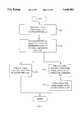
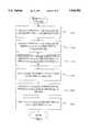
- FIG. 11is an operational flow diagram illustrating the manner in which message delivery service 900 stores and schedules messages (i.e. step 1012, FIG. 10) according to one embodiment of the invention.
- message delivery service 900receives a request for message delivery from user 106A.
- message delivery service 900receives and stores the message in message database 918.
- An access record corresponding to the stored messageis stored in access database 914. This occurs in a step 1112.
- message delivery system 902determines the message delivery schedule and stores a SCHEDULE EVENT in scheduler database 910. This occurs in steps 1116 and 1120.
- the SCHEDULE EVENTindicates the date and time at which a message delivery attempt is to be initiated.
- FIG. 9storage and retrieval of records in access database 914 and message database 918 are accomplished using access database service 912, message database service 916 and the appropriate front-end distributor 938.
- Front-end distributors 938according to one embodiment are fully described in the co-pending patent application entitled "Distributed Voice System and Method" as referenced above. Although the invention is illustrated and described in terms of this preferred embodiment, it will be apparent to a person skilled in relevant art that alternative systems and methods used for storing and retrieving records in databases (such as access database 914 and message database 918) can be used.
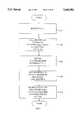
- FIG. 12, which comprises FIGS. 13, 14 and 15is an operational flow diagram that details a process for storing and recording messages according to one embodiment of the invention.
- FIG. 12(i.e., FIGS. 13, 14 and 15) illustrates in greater detail the operational flow illustrated in FIG. 11.
- a NEW CALL REQUESTenters message delivery service 900.
- call data 144is routed to network control processor 304 and call audio 142 is routed to matrix switch 306.
- network control processor 304determines whether operator assistance is required. Preferably, calls requiring operator assistance are routed to an automated voice response unit 334 to provide such assistance. In the case where user 106A desires to have a message delivered to user 106B, automated voice response unit 334 coordinates message delivery service 900 in this embodiment.
- user 106Ainitiates this message process by dialing into call processing system 302 using an enhanced services card and selecting the message delivery option. This selection can be made, for example, by pressing a key on the telephone key pad.
- automated voice response unit 334prompts user 106A for message delivery information.
- Automated voice response unit 334temporarily stores this information as it is being entered by user 106A.
- the message delivery information collectedcan include sender identification (e.g., the name of user 106A), recipient identification (e.g., the name of user 106B), the destination telephone number, and the date and time that delivery attempts are to be initiated (i.e., scheduling information).
- sender identificatione.g., the name of user 106A
- recipient identificatione.g., the name of user 106B
- the destination telephone numberi.e., the date and time that delivery attempts are to be initiated (i.e., scheduling information).
- Table 1illustrates an example of the data that can be collected and stored according to one embodiment of the invention.
- the automated voice response unit 334also prompts user 106A for the message itself.
- the prompting provided by automated voice response unit 334is accomplished by playing voice scripts to user 106A that request information be entered via the telephone key pad, voice response or electronic data. This embodiment where voice scripts are played to user 106A is ideal for providing instructions to a human sending the message.
- automated voice response unit 334can play scripts that are machine-readable.
- the scripts playedcan be data scripts that play tones or other machine-readable signals to the sending computer system.
- scriptsare stored and played to users 106, such as user 106A according to one embodiment, is described in co-pending patent application titled "Distributed Voice System and Method" as referenced above. Because unique scripts can be stored and played for a particular user 106 and/or a particular customer 110, special accounts can be set up to handle custom data communications as well as to provide custom voice scripting.
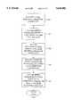
- automated voice response unit 334sends the first data packet of the message to message database 918. Specifically, in the embodiment illustrated in FIG. 9, automated voice response unit 334 sends this first packet to front-end distributor 938B for message database service 916.
- message front-end distributor 938Bassigns a message key to the data packet and returns this message key to automated voice response unit 334.
- the message keyis a unique identifier assigned to each message by front-end distributor 938B.
- message keysare returned for three components of the message: the sender's name, the recipient's name, and the message. The manner in which this is accomplished according to one embodiment is fully described in the co-pending patent application titled "Distributed Voice System and Method" as referenced above.
- front-end distributor 938Bforwards the message data packet to message database service 916 for storage in message database 918.
- automated voice response unit 334sends subsequent packets of the message to front-end distributor 938B using the assigned message key. This process continues until all remaining packets are sent. In one embodiment, the packets are identified using the message key assigned to the first data packet and using a sequential packet number. In step 1404, front-end distributor 938B sends these remaining message packets to message database service 916 for storage in message database 918.
- automated voice response unit 334sends an access record to front-end distributor 938A.
- This access recordincludes all relevant message information.
- This message informationcan include, but is not limited to, the destination telephone number, the time at which the message was recorded, the length of the message in seconds, the message key, a blank scheduler ID, a blank time delivered field, and a blank message access key.
- Table 2illustrates an example of the information contained in an access record according to one embodiment of the invention. Note that the scheduler ID field, time delivered field, and access field of the access record are blank at this stage of message processing.
- front-end distributor 938Aassigns an access key to the message and returns this access key to automated voice response unit 334.
- This access keyis a unique identifier that is used to retrieve the access record pertaining to a specific message delivery. As described below, it is message delivery controller 904 that uses this access key to retrieve the message delivery information.
- Front-end distributor 938Aforwards the access record including the assigned access key to access database service 912 for storage in access database 914. This occurs in a step 1416.
- Table 3illustrates the access record entries according to the example illustrated in Table 2. Note that at this stage of processing the access key field is no longer blank, as an access key has been assigned by front-end distributor 938A.
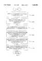
- the messageis stored in message database 918, an access record identifying pertinent information is stored in access database 914, and automated voice response unit 334 holds the unique identifier (i.e. the key) to this stored information.
- scheduling of the message deliverydoes not begin until all of these steps are accomplished.
- automated voice response unit 334sends a SCHEDULE EVENT REQUEST to message delivery controller 904 to schedule the message delivery.
- the SCHEDULE EVENT REQUESTcan be comprised of billing information, the access key, operator console allocation information, scheduling information, and next attempt time information.
- the operator console allocation informationcan include a network control processor call type, language information, and the device type array to be used for delivery of the message.
- the console allocation informationalso includes a DEF number.
- all informationis gathered for a particular account (i.e., at the customer or subscriber level) and stored in a DEF record on account basis. In this manner, efficiencies can be gained by establishing standard information on an account-by-account basis.
- Table 4illustrates an example of the information included in SCHEDULE EVENT REQUEST according to one embodiment of the invention.
- the network control processor (NCP) call typeis a representation (preferably numeric) of the type of call being placed.
- the NCP call typecould be, for example, record or delivery.
- Automated voice response unit 334can be assigned the ability to process message record call types and/or message delivery call types.
- the language fieldis a bit mask that is used to identify the language used to interface to user 106A and user 106B. Again, these can be set up on account-by-account basis so that each user 106 has his or her own language preferences specified. These can be identified by the user's account number, phone number, caller's ID, caller's carrier ID, and/or recipient's ID.
- the device typedefines the type of operator console 308 or other device, such as a modem or facsimile device, needed to process the call.
- Scheduling informationis used to determine the maximum number of delivery attempts and the number of minutes to wait between attempts.
- User 106Acan be prompted to provide scheduling information.
- the number of delivery attempts and the waiting period between attemptscan be configured on an account-by-account basis and stored in a DEF record.
- automated voice response unit 334obtains this delivery information for the message.
- additional informationis not part of the message delivery information retrieved from user 106A based on users prompts. Instead, this additional information is message delivery information that is configurable at the user, subscriber, and/or customer level, and is provided by message delivery service 900.
- the next attempt time informationcontains the time to begin message delivery as provided by user 106A during the collection of initial message delivery information.
- User 106Acan select a specific date and time to begin message delivery attempts, such as Tuesday at 7:15 p.m., or such as Feb. 12, 1995, at 7:15 p.m. eastern standard time. Alternatively, user 106A can indicate a period of time to wait before attempting delivery from the time the message is recorded.
- message delivery controller 904performs a time calculation to determine when to start the first message delivery attempt. This determination is made based on the scheduling and next attempt time information provided by automated voice response unit 334 in step 1420.
- the automated voice response unit 334provides the next attempt time variables to enable message delivery controller 904 to calculate the next attempt time. These variables are delivery status, time type and time value. These fields are represented in FIGS. 25 and 26 and are addressed in more detail below. During initial message delivery setup, message delivery controller 904 ignores the delivery status field because at this stage, this field is always set to "not delivered.”
- Time typerefers to the method used to determine the next retry attempt. Time type can have three values: not specified, actual, and minute offset.
- the "not specified” time typeuses the scheduling information to calculate a delivery time when a time has not been entered by the user.
- Actual timerefers to a future date and time entry specified by user 106A in step 1308.
- Minimum offsettype is a specific number of minutes (M) from the time at which the message is recorded. Preferably, the time is referenced based on Greenwich Mean Time (GMT). For example, a 15 minute offset means that the message delivery attempt would begin 15 minutes from the time that recording of the message from user 106A was completed.
- GTTGreenwich Mean Time
- message delivery controller 904uses the information sent in the SCHEDULE EVENT REQUEST (including the delivery time determined in step 1504) to compile a MAKE EVENT REQUEST.
- Message delivery controllersends the MAKE EVENT REQUEST to scheduler 908 to request that the scheduler 908 schedule the message delivery.
- Table 5illustrates an example of the information included in the MAKE EVENT REQUEST according to one embodiment of the invention.
- Scheduler 908is a database service that provides in one embodiment a C-tree interface to the call processing platform. It also performs three types of event operations: make, perform and remove.
- the MAKE EVENT REQUESTis received from message delivery controller 904 and creates a new event or updates an existing event.
- a PERFORM EVENTis generated by scheduler 908 when the event scheduled by the make event expires.
- the PERFORM EVENTis sent to a designated service, such as message delivery controller 904.
- the REMOVE EVENTis sent by a service and removes the event created by the MAKE EVENT REQUEST.
- the type of process to which scheduler 908 interfaces and the type of auxiliary data stored with the event requestdo not matter.
- multiple instances of scheduler 908can be included in message delivery system 902 to provide for redundancy.
- message delivery controller 904includes a blank scheduler ID field in the MAKE EVENT REQUEST.
- scheduler 908assigns a scheduler ID to the MAKE EVENT REQUEST and returns this scheduler ID to message delivery controller 904 in its response.
- the scheduler IDis a unique identifier that facilitates communication between scheduler 908 and its interfaces, such as message delivery controller 904 or a conference calling controller.
- the scheduler IDlinks scheduler 908 and its interfaces throughout the message delivery attempts. It is a value assigned to the MAKE EVENT REQUEST when that request is initially received by scheduler 908. Any updates to the MAKE EVENT REQUEST--such as storing a new delivery time when a delivery attempt has been unsuccessful--are identified in scheduler database 910 with the scheduler ID.
- the scheduler IDis removed only when scheduler 908 receives a REMOVE EVENT REQUEST to delete the data pertaining to a particular event, in this case, a message delivery.
- scheduler 908stores the MAKE EVENT REQUEST received from message delivery controller 904 in scheduler database 910 as a MAKE EVENT RECORD.
- the MAKE EVENT RECORDindicates that delivery of a particular message is to be initiated at a specific date and time.
- the scheduler ID assigned by scheduler 908is inserted in the scheduler ID field.
- message delivery controller 904forwards the scheduler ID received from scheduler 908 to automated voice response unit 334 in the SCHEDULE EVENT REQUEST response.
- automated voice response unit 334updates the access record in Access Database 914 for that message to include the scheduler ID assigned by scheduler 908.
- a NEXT EVENT TIMER in scheduler 908indicates when the next event is to take place.
- the schedulercalculates a NEXT EVENT TIME for the event that is to expire next.
- Message delivery controller 904informs the scheduler of the time of the event in the MAKE EVENT REQUEST.
- Scheduler 908calculates the amount of time (preferably the number of milliseconds) between the current time and the event time--the difference being the time until the event is to occur--and sets a next event timer.
- Scheduler 908is indifferent as to the type of scheduled event it is tracking.
- scheduler 908sends the event to the controller (message delivery 904, conference calling, facsimile, etc.) indicated by the service name in the MAKE EVENT REQUEST.
- any time another event is added or updated with a time less than the next scheduled eventthe time between the current time and the modified scheduled event is recalculated and the NEXT EVENT TIMER is updated to reflect the new event's time.
- scheduler 908retrieves all events that have the same event time from the database. These events relate to the delivery of different messages but are processed simultaneously by the service, in this case the message delivery controller 904.
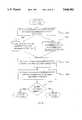
- FIG. 16is a high-level operational flow diagram illustrating a method by which a scheduled message is delivered to a user 106B.
- scheduler 908determines that it is time to deliver a message left by user 106A for user 106B. Scheduler 908 makes this determination when the NEXT EVENT TIMER expires.
- message delivery service 900begins the setup procedure for message delivery.
- automated voice response unit 334 and network control processor 304retrieve the message and deliver it to user 106B.
- the messageis deleted from message database 918.
- FIG. 17is an operational flow diagram illustrating the manner in which message delivery service 900 is set up for message delivery (i.e., step 1608).
- message delivery controller 904informs network control processor 304 that the message is to be delivered.
- network control processor 304starts a call process and informs automated voice response unit 334 that a message is to be delivered.
- automated voice response unitis set up for the message delivery.
- FIG. 18is an operational flow diagram illustrating a method by which message delivery service 900 retrieves and delivers the message to user 106B.
- automated voice response unit 334retrieves access data from access database 914 pertaining to the message to be delivered.
- network control processor 304originates a call to the user 106B that is to receive the message.
- automated voice response unit 334retrieves the message from message database 918 and delivers the message data to the user 106B via matrix switch 308.
- the call to user 106Bis terminated after the message is delivered.
- Steps 1608 and 1612 of FIG. 16have thus been described in greater detail with reference to FIGS. 17 and 18, respectively.
- the entire process of message deliveryis now described in still greater detail according to one embodiment of the invention. This description is made with reference to FIG. 19, which comprises FIGS. 20, 21, 22, 23, and 24.
- scheduler 908determines that it is time to deliver a message to user 106B. This determination is made by the NEXT EVENT TIME expiring as described above. When it is time to deliver a message, scheduler 908 notifies message delivery controller 904 that a message is to be delivered to user 106B. In one embodiment, this is accomplished by sending a PERFORM EVENT REQUEST message to message delivery controller 904.
- the PERFORM EVENT REQUESTcontains the information the message delivery controller sent to the scheduler in the MAKE EVENT REQUEST. This information can include base billing information, an access key, operator console allocation and scheduling information and scheduler ID. An example of the information contained in the PERFORM EVENT REQUEST message is illustrated in Table 6 according to one embodiment of the invention.
- a procedure instancesis a portion of the message delivery controller program that performs a specific task and is identified by a unique procedure ID.
- a procedure IDidentifies a single procedure instance for a single delivery attempt.
- the procedure instance routineadds the procedure ID and the scheduler ID from the PERFORM EVENT REQUEST to a scheduler ID list in message delivery controller 904.
- the message delivery controllerFor each new attempt to deliver the message, the message delivery controller checks the scheduler ID list for the presence of the scheduler ID associated with the current message. If the scheduler ID for the message already exists in the scheduler ID list, no new procedure instance is created for a delivery attempt. This is because the presence of the scheduler ID on the list indicates the message delivery process is in progress.
- scheduler 908performs polling of the message delivery controller 904. This is a precautionary action. If the message delivery system 902 or any of its related systems, such as network control processor 304 or automated voice response unit 334, have an interruption in service, it is possible that the PERFORM EVENT REQUEST, which includes the scheduler ID, could be lost. The message delivery controller 904 would be unaware that a timer had expired and an event was to be performed. To safeguard against this possibility, scheduler 908 periodically resends the PERFORM EVENT REQUEST to the message delivery controller 904 at an interval specified in the polling time. If the message delivery controller 904 has the PERFORM EVENT REQUEST, it responds to indicate that the scheduler ID is on the scheduler ID list. If the scheduler ID is not on the list, message delivery controller 904 adds it to the list.
- message delivery controller 904If the system is already busy with a configurable number of requests, message delivery controller 904 returns a "BACK OFF" RESPONSE to scheduler 908. This command tells scheduler 908 to increase the time between polling requests.
- message delivery controller 904notifies network control processor 304 that it is time to initiate message delivery. In one embodiment, this is accomplished by the procedure instance sending an INITIATE MESSAGE DELIVERY (MD) REQUEST to network control processor 304.
- MDINITIATE MESSAGE DELIVERY
- This requestpreferably contains a DEF number, a network control processor call type, billing information, a language type, and device type array.
- the DEF numberis used by automated voice response unit 334 to retrieve a DEF record from DEF service 932, indicating how to handle the message delivery in this particular instance.
- the language fieldis used to specify a language
- the device type arrayspecifies the type of device required, such as an automated voice response unit 334 or facsimile device.
- a new callis generated within network control processor 304, rather than in matrix switch 308.
- An example of the INITIATE MD REQUESTis illustrated in Table 7 according to one embodiment of the invention.
- network control processor 304sends a call handle to message delivery controller 904.
- the call handle contained in the response to the INITIATE MD REQUESTis placed in the scheduler ID list by message delivery controller 904.
- the call handleis a unique call identifier that ties message delivery controller 904 with network control processor 304.
- the call handleis used to relate a particular call setup in network control processor 304 with a specific message attempt, as several message deliveries can be taking place at the same time.
- the scheduler IDis the key that uniquely identifies the event within scheduler 908 and message delivery controller 904.
- the message keyis the connection between the access database service 912 and the message database service 916.
- Each keyis designed for a particular service, but can be distributed to more than one service to facilitate troubleshooting. Keys can then be matched to trace a call process. Another reason that keys are distributed to other services is so they are already available if they are needed for a new portion of the process or for maintenance.
- the scheduler IDis common between scheduler 908, message delivery controller 904, automated voice response unit 334 and the access record.
- the procedure instancestores the call handle and the procedure ID in a call handle list. In this manner, the scheduler ID and call handle can be matched for a particular message delivery by matching the procedure ID.
- network control processor 304notifies automated voice response unit 334 that the message is to be delivered. This enables the automated voice response unit 334 to set up for message delivery. In one embodiment, this is accomplished by sending a NEW CALL REQUEST to automated voice response unit 334.
- the NEW CALL REQUESTincludes the call handle assigned by the network control processor 304, operator console allocation information including the DEF number, and other information pertaining to the call.
- Table 8An example of the information contained in the NEW CALL REQUEST according to one embodiment of the invention is illustrated in Table 8.
- automated voice response unit 334uses the DEF number sent by network control processor 304 to retrieve a DEF record from DEF service 932.
- the DEF recordcontains complete instructions regarding how to process the message delivery.
- the DEF recordcan be established based on user 106, subscriber 114, or customer 110 information. As a result, the DEF record can contain instructions that are unique, or customized, at the user and/or customer level.
- message deliverycan be customized for various users and/or customers.
- network control processor 304queues the request until an automated process is available. If the allotted time in the queue is exceeded, message delivery controller 904 cancels the request to the network control processor 304 to remove the queued request. As a result, the message is not delivered. Note that in this situation, a field indicating the number of attempts for message delivery is not increased to reflect this "attempted delivery.”
- the automated voice response unit 334requests information about the message from the message delivery controller 904.
- This requestincludes the call handle, which uniquely identifies the call to message delivery controller 904.
- Message delivery controller 904looks in the call handle list for the call handle. When message delivery controller 904 finds the call handle, it sends the MESSAGE DELIVERY (MD) INFO REQUEST to the procedure that registered the call handle. In this manner, message delivery controller 904 can determine the message for which automated voice response unit 334 is requesting information. As a result, message delivery system 902 can handle multiple simultaneous message deliveries by one or more automated voice response units 334.
- MDMESSAGE DELIVERY
- message delivery controller 904returns the access key for the message delivery to the automated voice response unit 334.
- automated voice response unit 334retrieves the access record for the message delivery from access database 914.
- the retrieved access recordcontains the destination telephone number, the time the message was recorded, length of the message, one or more message keys, the scheduler ID and a blank time-delivered field. This is accomplished in a step 2112.
- the automated voice response unit 334requests that network control processor 304 originate a call to the message recipient, user 106B.
- This requestincludes the destination telephone number that automated voice response unit 334 obtained from the access record in step 2112.
- This requestincludes the call handle to identify the call as well as other call processing information.
- automated voice response unit 334starts a timer that measures the amount of time elapsed until the call is answered by user 106B.
- a timer limitis set such that if the timer meets this limit (preferably specified in seconds), the call is released.
- the NO ANSWER TIMERlimits the time a device (e.g., telephone, modem, fax machine, etc.) can "ring" before message delivery service 900 disconnects the call attempt.
- network control processor 304originates a call to user 106B so the message can be delivered. Once the call is originated, a call can be either answered or unanswered.
- the scenario illustrated in FIG. 22assumes that the call is answered and a connection established.
- network control processor 304informs automated voice response unit 334 that user 106B has answered the call. In one embodiment, this is accomplished by sending an ANSWER REQUEST message to automated voice response unit 334.
- automated voice response unit 334marks the message delivery status as "delivered" and prompts user 106B for input regarding message delivery. In one embodiment, this prompting is accomplished by playing a voice script accessed from a voice script service as described in the co-pending patent application titled "Distributed Voice System And Method" as referenced above.
- automated voice response unit 334retrieves the message from message database service 916 and, in a step 2220, delivers this message to user 106B.
- the messageis stored in and retrieved from message database service 916 as described in the co-pending patent application titled "Distributed Voice System And Method" as referenced above. It should be noted that the message could be of any type including, but not limited to, a facsimile message, a data message, or a voice message.
- the messageis stored in message database 918 in a digitized format.
- information delivered along with the messagecan include but is not limited to sender name, recipient name, and the actual recorded message.
- automated voice response unit 334informs network control processor 304 that the call to the called party can be released. Also, in a step 2228, automated voice response unit 334 notifies message delivery controller 904 via a MESSAGE DELIVERY (MD) COMPLETE REQUEST that the message has been delivered. The message is identified by the call handle assigned to the call and sent in the MESSAGE DELIVERY (MD) COMPLETE REQUEST and is passed to the message delivery controller in step 2012. It should be noted that if the delivery attempt is unsuccessful, in one embodiment, automated voice response unit 334 notifies message delivery controller 904 that the message was not delivered.
- MDMESSAGE DELIVERY
- message delivery controller 904checks to determine whether the message is delivered. In one embodiment, this is accomplished by checking a status field that indicates whether the message has been delivered. If the message has been delivered, in a step 2308, message delivery controller 904 informs automated voice response unit 334 that the message can be deleted. In one embodiment, this is accomplished by setting a delete flag indicating that data pertaining to the particular message delivery may be deleted and by returning this delete flag to automated voice response unit 334.
- automated voice response unit 334receives and checks the delete flag in step 2312, it sends a DELETE DATA REQUEST to message database service 916 and access database service 912 to delete the associated records from message database 918 and access database 914. This is accomplished in step 2316.
- message delivery controller 904sends a REMOVE EVENT REQUEST to scheduler 908. This contains the scheduler ID. Scheduler 908 removes the record from scheduler database 910.
- the responsibility for storing, retrieving, and deleting records from message database 918 and access database 914is delegated to automated voice response unit 334. This is done because the automated voice response unit 334, using distributed voice, created the message and access record. Therefore, the automated voice response unit 334 deletes the records.
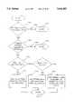
- FIGS. 22 and 23are discussed in terms of the scenario where the call is answered. If, on the other hand, the call is not answered, at least two additional scenarios are possible: (1) the line is busy, or (2) the called party does not pick up the telephone. In either case, automated voice response unit 334 informs message delivery controller 904 that the message was not delivered.
- a step 2408if the line is busy, network control processor 304 sends a terminate message to automated voice response unit 334.
- a common channel signalling system 7 (SS7) out-of-band signalling channelcan be used to determine whether the line is busy.
- SS7common channel signalling system 7
- the automated voice response unit 334requests that network control processor 304 release the call.
- step 2416automated voice response unit 334 informs the message delivery controller 904 that the call was not completed, and thus the message was not delivered.
- message delivery controller 904checks the number of remaining delivery attempts to determine whether additional attempts are to be made. If additional attempts remain, the operation continues as illustrated in FIG. 28. If there are no additional retry attempts remaining, the operation continues as illustrated in FIG. 29. FIGS. 28 and 29 are discussed in detail below.
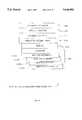
- FIG. 25is a block diagram illustrating a scheduling information structure used to determine the strategy for message delivery according to one embodiment.
- Scheduling information in the scheduling information structure 2500includes maximum attempts field 2504, default minutes field 2508, current attempt field 2512, and an array of attempt times field 2516.
- the maximum attempts field 2504indicates a total number of attempts that will be permitted to deliver the message. If the message cannot be delivered in this number of attempts, the message is marked as not delivered and the message information is deleted.
- Default minutes field 2508indicates the number of minutes that message delivery service 900 waits between delivery attempts if there is not a value in the field for array of attempt times 2516. The default minutes field 2508 is used to determine the next delivery time.
- the current attempt field 2512is the number of attempts made to deliver the message. Each time an attempt is made, this field is incremented by one. This current attempt field 2512 also serves as an index to the array of attempt times field 2516.
- the array of attempt times field 2516has two components. These two components are a size field 2520 and the elements field 2524. Size field 2520 indicates the number of elements 2524 in the array. Thus, if the size of the army is zero, there are no elements 2524 in the array. Similarly, if the size of the array is three, there are three elements 2524 in the array.
- Each element 2524 in the armyis a guide to the number of minutes between attempts for a specific retry attempt. For example, if the value of the current attempt field 2512 is two, representing the second attempt, the array of attempt times field 2516 accessed would be that element 2524 corresponding to the second attempt--minutes attempt ⁇ 2 ⁇ 2524B.
- the number of minutes to delay the delivery for the minutes attempt ⁇ 2 ⁇ 2524Bcould be any number, such as 20 minutes.
- Each minutes attempt element 2524could be different from the others, thus specifying different amounts of delay between attempts.
- Automated voice response unit 334provides the next attempt time information 2600: delivery status 2604, time type 2608, and time value 2612. These variables are illustrated in FIG. 26. Delivery status 2604 could be delivered 2604A or not delivered 2604B.
- Time type 2608could be not specified type 2608A, actual time type 2608B, or a minute offset type 2608C specifying ⁇ N ⁇ number of minutes.
- the not specified type 2608Auses scheduling information when a time has not been entered by user 106A.
- the actual time type 2608Brefers to an hour and minute entry placed by user 106A specifying the time delivery is to be made.
- the minute offset type 2608Cspecifies a specific number of minutes from the time the message is recorded. For example, a 15 minute offset means that the message delivery attempt could begin 15 minutes from the time message recording was completed.
- the time value variables 2612include a future date and time variable 2612A and a current date and time plus N minutes variable 2612B. If the actual time type 2608B is selected by user 106A by entering a specific date and time, future date and time variable 2612A is used. If the time type variable 2608 selected by user 106A is minute offset type 2608C, current date and time plus N minutes variable 2612B is used, where N represents the number of minutes that the delivery is offset from the recording time.
- FIGS. 25 and 26are used to make the next attempt time calculation by message delivery controller 904. The process by which this is accomplished according to one embodiment is illustrated in FIG. 27.
- a step 2704if the delivery status equals ⁇ not delivered, ⁇ the time for the next delivery attempt may need to be calculated. If, on the other hand, the message is delivered, no calculation needs to be performed as illustrated by flow line 2706 and done step 2707.
- message delivery controller 904next determines whether the current attempt is less than the maximum number of attempts specified. This is done by comparing current attempt field 2512 with the maximum attempts 2504 specified. If the current number of attempts meets the maximum, the calculation need not be performed, as no more attempts are to be made. This is illustrated by flow line 2709 and done block 2710.
- message delivery controller 904determines the time at which the next delivery attempt should be made. If, in step 2711, the time type variable 2608 is the not specified type 2608A, the time is calculated in a step 2712 from scheduling information. If the time type variable is the actual time type 2608B, message delivery controller 904 uses the future date and time specified in future date and time variable 2612A.
- message delivery controller 904uses the current date and time plus the offset value N in minutes from time value variable 2612B to calculate a new delivery time. This offset value is entered by user 106A when the message delivery is being set up.
- FIG. 28is an operational flow diagram illustrating the steps followed when a retry attempt is scheduled.
- message delivery controller 904determines whether additional retry attempts remain. The manner in which message delivery controller 904 determines whether additional retry attempts remain (step 2424) is by comparing the maximum attempts field 2504 with the current attempt field 2512. If the current attempt field 2512 equals maximum attempts field 2504, no retry attempts remain.
- message delivery controller 904determines the time at which the next delivery attempt is to be made and increases the current attempt field 2512.
- message delivery controller 904instructs scheduler 908 to reschedule the delivery attempt.
- the same scheduler IDis used, but the new record replaces the old record containing the previous delivery time.
- scheduler 908stores the new MAKE EVENT REQUEST in scheduler database 910 so that a retry attempt can be initiated at the scheduled time.
- the message delivery controller 904sends a MAKE EVENT REQUEST to the scheduler 908 using the new scheduled time.
- the procedure instancecleans up the previous attempt by removing the scheduler ID and call handle from their respective lists. Then the procedure instance is eliminated.
- message delivery controller 904When it is time for the next delivery attempt for this message, message delivery controller 904 does not find the scheduler ID on the scheduler ID list. Therefore, message delivery controller 904 adds a scheduler ID to the list for the current attempt.
- call handlewill be different from the call handle assigned to the first attempt.
- a call handleonly can be added to the call handle list when a response to the INITIATE MESSAGE DELIVERY (MD) REQUEST is received.
- the call handle listserves as protection against aborted delivery attempts caused by system failure. If the attempt to set up a message delivery is unsuccessful due to a system failure, the procedure instance removes the scheduler ID and the call handle from their respective lists, and then the procedure instance is eliminated. Each time the scheduler sends a PERFORM EVENT REQUEST, a new procedure instance is created and the process defined previously repeats.
- the call handle listalso serves to clean up incomplete calls, as illustrated in the following example. Assuming no automated voice response unit 334 is available to handle a NEW CALL REQUEST from the network control processor 304, the call is queued and eventually times out.
- the message delivery controller 904sends a RELEASE REQUEST to network control processor 304 to release the call. Message delivery controller 904 also removes the call handle from the call handle list.
- Network control processor 304could be in the process of dequeuing the call when the RELEASE REQUEST is sent by message delivery controller 904.
- One step in dequeuing a callis sending a NEW CALL REQUEST to automated voice response unit 334. It is possible that automated voice response unit 334 receives the NEW CALL REQUEST before the RELEASE REQUEST is processed by network control processor 304.
- the NEW CALL REQUESTprompts automated voice response unit 334 to send a MESSAGE DELIVERY (MD) INFO REQUEST to message delivery controller 904.
- MDMESSAGE DELIVERY
- Message delivery controller 904checks the call handle list for this call and does not find the call handle, since it has already been removed by the RELEASE REQUEST.
- Message delivery controller 904returns an error to the process that sent the MESSAGE DELIVERY (MD) INFO REQUEST, in this case automated voice response unit 334, indicating that the call handle was not found.
- the automated voice response unit 334cleans up its portion of the unnecessary call and is ready for another call.
- FIG. 29is an operational flow diagram illustrating the process that occurs when a message is not delivered and no retry attempts remain.
- message delivery controller 904sets a delete flag and sends this delete flag to automated voice response unit 334.
- automated voice response unit 334checks the delete data flag and deletes the data records from message database 918 and access database 914 for the message as illustrated in step 2912.
- message delivery controller 904sends a REMOVE EVENT REQUEST to scheduler 908. This contains the scheduler ID.
- Scheduler 908removes the record from scheduler database 910.
Landscapes
- Engineering & Computer Science (AREA)
- Signal Processing (AREA)
- Telephonic Communication Services (AREA)
Abstract
Description
TABLE 1 ______________________________________ COLLECTED DATA ______________________________________ Sender Name Recipient Name Message Destination Telephone Number Time to Begin Delivery Attempt ______________________________________
TABLE 2 ______________________________________ ACCESS RECORD ______________________________________ Destination Telephone Number Time Message Recorded Length of Message Message Key Scheduler ID (Blank) Time Delivered Field (Blank) Access Key (Blank) ______________________________________
TABLE 3 ______________________________________ ACCESS RECORD ______________________________________ Destination Telephone Number Time Message Recorded Length of Message Message Key Scheduler ID (Blank) Time Delivered Field (Blank) Access Key ______________________________________
TABLE 4 ______________________________________ SCHEDULE EVENT REQUEST ______________________________________ Base Billing Information Access Key Operator Console Allocation Information DEF Number NCP Call Type Language Device Type Scheduling Information Maximum Attempts Default Minutes Current Attempt (blank) Array of Attempt Times Next Attempt Time Information Delivery Status (blank) Time Type Time Value ______________________________________
TABLE 5 ______________________________________ MAKE EVENT REQUEST ______________________________________ Base Billing Information Access Key Operator Console Allocation Information DEF Number NCP Call Type Language Device Type Scheduling Information Maximum Attempts Default Minutes Current Attempt Array of Attempt Times Actual Delivery Time Derived From Next Attempt Time Calculation Polling Time Scheduler ID (Blank) Service Name ______________________________________
TABLE 6 ______________________________________ PERFORM EVENT REQUEST ______________________________________ Base Billing Information Access Key Operator Console Allocation Information DEF Number NCP Call Type Language Device Type Scheduling Information Maximum Attempts Default Minutes Current Attempt Array of Attempt Times Scheduler ID ______________________________________
TABLE 7 ______________________________________ INITIATE MD REQUEST ______________________________________ Base Billing Information Operator Console Allocation Information DEF Number NCP Call Type Language Device Type ______________________________________
TABLE 8 ______________________________________ NEW CALL REQUEST ______________________________________ Call Handle Other Call Processing Information Operator Console Allocation Information DEF Number NCP Call Type Language Device Type ______________________________________
Claims (20)
Priority Applications (1)
| Application Number | Priority Date | Filing Date | Title |
|---|---|---|---|
| US08/366,559US5646982A (en) | 1994-12-30 | 1994-12-30 | System and method for message delivery |
Applications Claiming Priority (1)
| Application Number | Priority Date | Filing Date | Title |
|---|---|---|---|
| US08/366,559US5646982A (en) | 1994-12-30 | 1994-12-30 | System and method for message delivery |
Publications (1)
| Publication Number | Publication Date |
|---|---|
| US5646982Atrue US5646982A (en) | 1997-07-08 |
Family
ID=23443539
Family Applications (1)
| Application Number | Title | Priority Date | Filing Date |
|---|---|---|---|
| US08/366,559Expired - LifetimeUS5646982A (en) | 1994-12-30 | 1994-12-30 | System and method for message delivery |
Country Status (1)
| Country | Link |
|---|---|
| US (1) | US5646982A (en) |
Cited By (108)
| Publication number | Priority date | Publication date | Assignee | Title |
|---|---|---|---|---|
| US5859939A (en)* | 1997-02-25 | 1999-01-12 | Mci Communications Corporation | Method and system for equalizing PMD using incremental delay switching |
| US5867494A (en)* | 1996-11-18 | 1999-02-02 | Mci Communication Corporation | System, method and article of manufacture with integrated video conferencing billing in a communication system architecture |
| US5867495A (en)* | 1996-11-18 | 1999-02-02 | Mci Communications Corporations | System, method and article of manufacture for communications utilizing calling, plans in a hybrid network |
| US5956165A (en)* | 1997-09-12 | 1999-09-21 | Mci Communications Corporation | Method and apparatus for updating subcarrier modulation in a communication network |
| US5995596A (en)* | 1997-03-12 | 1999-11-30 | Siemens Information And Communication Networks, Inc. | System and method for coordination of multimedia messages across multiple systems |
| US5999525A (en)* | 1996-11-18 | 1999-12-07 | Mci Communications Corporation | Method for video telephony over a hybrid network |
| WO2000005861A1 (en)* | 1998-07-24 | 2000-02-03 | Motorola Inc. | Telecommunication audio processing systems and methods therefor |
| US6052440A (en)* | 1998-10-29 | 2000-04-18 | Samsung Electronics Co., Ltd. | System and method of delivering a multimedia alarm call message |
| US6115455A (en)* | 1996-11-05 | 2000-09-05 | Boston Technology, Inc. | Method and apparatus for dynamically creating message mailboxes |
| US6137864A (en)* | 1997-07-25 | 2000-10-24 | Lucent Technologies Inc. | Specifiable delete times for voice messaging |
| US6163800A (en)* | 1995-10-19 | 2000-12-19 | Canon Kabushiki Kaisha | Data communication apparatus and method |
| US6169786B1 (en)* | 1997-02-28 | 2001-01-02 | At&T Corp | Method for accomplishing complete re-dial |
| US6169734B1 (en) | 1996-12-31 | 2001-01-02 | Mci Communications Corporation | Internet phone set |
| US6195418B1 (en) | 1997-12-31 | 2001-02-27 | Alcatel Usa, Inc. | Telephone system having a callback capability and method for connecting a recipient of a message to a caller |
| US6243444B1 (en)* | 1999-04-08 | 2001-06-05 | International Thinklink Corporation | Apparatus and method for local intercept and service of long-distance calls |
| US6252917B1 (en)* | 1998-07-17 | 2001-06-26 | Nortel Networks Limited | Statistically multiplexed turbo code decoder |
| US6259772B1 (en)* | 1997-02-26 | 2001-07-10 | British Telecommunications Plc | Message delivery system with special features |
| WO2000074358A3 (en)* | 1999-06-01 | 2001-12-06 | Evoice Inc | Voice messaging system |
| US6335927B1 (en) | 1996-11-18 | 2002-01-01 | Mci Communications Corporation | System and method for providing requested quality of service in a hybrid network |
| WO2002001842A1 (en)* | 2000-06-28 | 2002-01-03 | Ringminder, Inc. | Computerized system for the receipt, recordation, scheduling and redelivery of telephone messages to predetermined telephone numbers |
| US20020002633A1 (en)* | 2000-06-23 | 2002-01-03 | Colling John K. | Event notification system |
| WO2001071925A3 (en)* | 2000-03-22 | 2002-01-24 | Dora Internat | Universal communications system |
| US6345279B1 (en)* | 1999-04-23 | 2002-02-05 | International Business Machines Corporation | Methods and apparatus for adapting multimedia content for client devices |
| US20020052923A1 (en)* | 1999-01-15 | 2002-05-02 | Anderson Eric D. | Method and system for centralized storage and management of electronic messages |
| US6389283B1 (en)* | 1998-10-15 | 2002-05-14 | Telefonaktiebolaget Lm Ericsson (Publ) | Release of remaining activities in VPLMNs |
| US6407341B1 (en) | 2000-04-25 | 2002-06-18 | International Business Machines Corporation | Conductive substructures of a multilayered laminate |
| US6438217B1 (en) | 1999-03-11 | 2002-08-20 | Microsoft Corporation | Apparatus and method for future transmission of device-independent messages |
| US6456594B1 (en) | 1996-10-31 | 2002-09-24 | Connect One, Llp | Multi-protocol communications routing optimization |
| US20020136367A1 (en)* | 1997-03-13 | 2002-09-26 | Elsey Nicholas J. | Technique for facilitating communications with a party after initial unsuccessful communications therewith |
| US20020147775A1 (en)* | 2001-04-06 | 2002-10-10 | Suda Aruna Rohra | System and method for displaying information provided by a provider |
| US6473404B1 (en) | 1998-11-24 | 2002-10-29 | Connect One, Inc. | Multi-protocol telecommunications routing optimization |
| EP1278358A1 (en)* | 2001-07-17 | 2003-01-22 | BRITISH TELECOMMUNICATIONS public limited company | Scheduled Emergency Callback and Outcall Service |
| US6535585B1 (en)* | 2000-03-30 | 2003-03-18 | Worldcom, Inc. | System and method for notification upon successful message delivery |
| US20030061218A1 (en)* | 2000-02-18 | 2003-03-27 | Iyer Balakrishna Raghavendra | Method and system for utilizing a database as a service |
| EP0892539A3 (en)* | 1997-07-15 | 2003-05-07 | Avaya Technology Corp. | Voice messaging system with non-user outcalling and auto-provisioning capabilities |
| US20030142799A1 (en)* | 2002-01-31 | 2003-07-31 | Candell Emily A. | Methods and systems for providing voicemail services |
| US6604149B1 (en) | 1998-09-22 | 2003-08-05 | Microsoft Corporation | Method and apparatus for identifying individual messages in a single compressed data packet |
| US20030179873A1 (en)* | 2001-05-16 | 2003-09-25 | Yihua Chen | Method and networking architecture for implementing service voice dynamic loading on intelligent network |
| US6681001B1 (en) | 1996-02-14 | 2004-01-20 | Nortel Networks Limited | Computer integrated telecommunications systems and methods |
| US6690654B2 (en) | 1996-11-18 | 2004-02-10 | Mci Communications Corporation | Method and system for multi-media collaboration between remote parties |
| US20040039596A1 (en)* | 2002-08-21 | 2004-02-26 | Communitect, Inc. | Method and system for scheduling and transmitting multiple message types |
| US20040044736A1 (en)* | 2002-08-27 | 2004-03-04 | Austin-Lane Christopher Emery | Cascaded delivery of an electronic communication |
| US20040059790A1 (en)* | 2002-08-27 | 2004-03-25 | Austin-Lane Christopher Emery | Delivery of an electronic communication using a lifespan |
| US6731725B1 (en)* | 1999-06-28 | 2004-05-04 | Keith A. Merwin | Computerized system for the receipt, recordation, scheduling and redelivery of telephone messages |
| US6732185B1 (en)* | 2000-07-24 | 2004-05-04 | Vignette Corporation | Method and system for managing message pacing |
| US6731625B1 (en) | 1997-02-10 | 2004-05-04 | Mci Communications Corporation | System, method and article of manufacture for a call back architecture in a hybrid network with support for internet telephony |
| US6754181B1 (en) | 1996-11-18 | 2004-06-22 | Mci Communications Corporation | System and method for a directory service supporting a hybrid communication system architecture |
| US6760412B1 (en) | 1999-12-21 | 2004-07-06 | Nortel Networks Limited | Remote reminder of scheduled events |
| US20040185834A1 (en)* | 2003-03-21 | 2004-09-23 | Daniel Sommers | Method for enabling IP push capability to wireless devices on a wireless network |
| US20040258215A1 (en)* | 2003-06-20 | 2004-12-23 | Devito Nicholas Michael | Method for sending a short message from a wireline phone |
| US6870918B1 (en)* | 1998-02-25 | 2005-03-22 | British Telecommunication Public Limited Company | Method and system for processing a call associated with a caller's account identity |
| US20050074112A1 (en)* | 2003-10-01 | 2005-04-07 | Timmins Timothy A. | Technique for sharing information through an information assistance service |
| US6909780B1 (en)* | 1999-01-13 | 2005-06-21 | Altigen Communications, Inc. | Voice mail call out method and apparatus |
| US20050193076A1 (en)* | 2004-02-17 | 2005-09-01 | Andrew Flury | Collecting, aggregating, and managing information relating to electronic messages |
| US20050207552A1 (en)* | 2003-08-11 | 2005-09-22 | Arbinet-Thexchange, Inc. | Method and system for processing call setup messages using call attributes |
| US6950502B1 (en)* | 2002-08-23 | 2005-09-27 | Bellsouth Intellectual Property Corp. | Enhanced scheduled messaging system |
| US20050265319A1 (en)* | 2004-05-29 | 2005-12-01 | Clegg Paul J | Method and apparatus for destination domain-based bounce profiles |
| US20060010216A1 (en)* | 2004-05-26 | 2006-01-12 | Techfirm Inc. | Mail distributing apparatus, program and mail transmitting method capable of shortening average wait time for completing transmission of mails |
| US20060014527A1 (en)* | 2004-07-15 | 2006-01-19 | Pantech Co., Ltd. | Apparatus and method for transmitting voice message in mobile communication terminal |
| GB2416643A (en)* | 2004-07-24 | 2006-02-01 | Ryan Nicholas Garnish | Telephone based reminder system |
| US20060059238A1 (en)* | 2004-05-29 | 2006-03-16 | Slater Charles S | Monitoring the flow of messages received at a server |
| US20060136545A1 (en)* | 2000-07-24 | 2006-06-22 | Brian Reistad | Method and system for facilitating marketing dialogues |
| US20060189333A1 (en)* | 2003-09-12 | 2006-08-24 | Core Mobility, Inc. | Unified interface for voice, text or picture message authoring |
| US7133840B1 (en)* | 1994-01-03 | 2006-11-07 | Kenna Janine S | Integrated nested account financial system with medical savings subaccount |
| US7133687B1 (en)* | 2003-04-03 | 2006-11-07 | Core Mobility, Inc. | Delivery of voice data from multimedia messaging service messages |
| US7145898B1 (en) | 1996-11-18 | 2006-12-05 | Mci Communications Corporation | System, method and article of manufacture for selecting a gateway of a hybrid communication system architecture |
| FR2888448A1 (en)* | 2005-07-07 | 2007-01-12 | Frederic Itey | Fixed or mobile telephone for telephone network, has automatic call procedure control allowing to detect stalling of called telephone, detect end of transmission of recorded voice message and call recipient if communication is not completed |
| US7224777B1 (en)* | 2003-12-03 | 2007-05-29 | Union Beach, L.P. | Time-controlled messaging system |
| US20070186280A1 (en)* | 2003-04-22 | 2007-08-09 | Cisco Technology, Inc. | System and Method for Distributing Information in a Network Environment |
| US20070286364A1 (en)* | 2003-01-03 | 2007-12-13 | At&T Bls Intellectual Property, Inc., A Formerly Known As Bellsouth Intellectual Property Corp. | Systems and Methods for Information Provision |
| US7313229B1 (en)* | 2001-12-28 | 2007-12-25 | At&T Bls Intellectual Property, Inc. | System and method for delayed or repeated message delivery |
| US7317929B1 (en) | 2003-04-03 | 2008-01-08 | Core Mobility, Inc. | Delivery of voice data from multimedia messaging service messages |
| US7327834B1 (en)* | 2004-07-02 | 2008-02-05 | Nortel Networks Limited | Method and system for providing interactive event reminders |
| US20090003555A1 (en)* | 2007-06-28 | 2009-01-01 | Embarq Holdings Company, Llc | System and method for an outbound greeting |
| US20090310598A1 (en)* | 2006-05-10 | 2009-12-17 | Hjalmar Winbladh | Telephone communication |
| US7640306B2 (en) | 2002-11-18 | 2009-12-29 | Aol Llc | Reconfiguring an electronic message to effect an enhanced notification |
| US7664097B2 (en) | 1996-04-18 | 2010-02-16 | Verizon Services Corp. | Telephone service via networking |
| US20100064057A1 (en)* | 2002-11-20 | 2010-03-11 | Corybant, Inc. | Interactive Voice Enabled Email Notification and Alert System and Method |
| US20100091687A1 (en)* | 2008-10-15 | 2010-04-15 | Ted Beers | Status of events |
| US7715371B2 (en) | 1995-12-11 | 2010-05-11 | Comcast Ip Holdings I, Llc | Method and apparatus for accessing communication data relevant to a target entity identified by a number string |
| US7813332B1 (en) | 1997-03-19 | 2010-10-12 | Verizon Services Corp. | Voice call alternative routing through PSTN and internet networks |
| US7817619B1 (en) | 1996-12-18 | 2010-10-19 | Verizon Services Corp. | Internet long distance telephone service |
| US7830860B2 (en) | 1997-03-11 | 2010-11-09 | Verizon Services Corp. | Packet data network voice call quality monitoring |
| US7835344B1 (en) | 1997-03-19 | 2010-11-16 | Verizon Services Corp. | Transport of caller identification information through diverse communication networks |
| US7948968B2 (en) | 1997-09-16 | 2011-05-24 | Verizon Communications Inc. | Network session management |
| US8358762B1 (en) | 2005-03-21 | 2013-01-22 | Aol Inc. | Conference calls and meetings via electronic messaging interface |
| US8379531B2 (en) | 1996-04-18 | 2013-02-19 | Verizon Services Corp. | Telephony communication via varied redundant networks |
| US8412786B2 (en) | 2010-04-20 | 2013-04-02 | Sprint Communications Company L.P. | Decomposition and delivery of message objects based on user instructions |
| US8452849B2 (en) | 2002-11-18 | 2013-05-28 | Facebook, Inc. | Host-based intelligent results related to a character stream |
| US8548433B1 (en) | 2007-06-27 | 2013-10-01 | Smith Micro Software, Inc. | Voice messaging service for network-based instant connect systems |
| US8571584B1 (en) | 2003-04-03 | 2013-10-29 | Smith Micro Software, Inc. | Delivery of voice data from multimedia messaging service messages |
| US8577972B1 (en) | 2003-09-05 | 2013-11-05 | Facebook, Inc. | Methods and systems for capturing and managing instant messages |
| US8701014B1 (en) | 2002-11-18 | 2014-04-15 | Facebook, Inc. | Account linking |
| US8874672B2 (en) | 2003-03-26 | 2014-10-28 | Facebook, Inc. | Identifying and using identities deemed to be known to a user |
| US8965964B1 (en) | 2002-11-18 | 2015-02-24 | Facebook, Inc. | Managing forwarded electronic messages |
| US9001819B1 (en)* | 2010-02-18 | 2015-04-07 | Zvi Or-Bach | Systems and methods for visual presentation and selection of IVR menu |
| US20150223024A1 (en)* | 2012-08-07 | 2015-08-06 | Stonethrow Telecommunications Ltd. | System for automatically matching a service requestor with a service provider based on their proximity and establishing a voice call between them |
| US9191505B2 (en) | 2009-05-28 | 2015-11-17 | Comcast Cable Communications, Llc | Stateful home phone service |
| US9203879B2 (en) | 2000-03-17 | 2015-12-01 | Facebook, Inc. | Offline alerts mechanism |
| US9203647B2 (en) | 2002-11-18 | 2015-12-01 | Facebook, Inc. | Dynamic online and geographic location of a user |
| US9246975B2 (en) | 2000-03-17 | 2016-01-26 | Facebook, Inc. | State change alerts mechanism |
| US20160050291A1 (en)* | 2013-04-15 | 2016-02-18 | Robert Bosch Gmbh | Communication method for transmitting useful data and corresponding communication system |
| US9319356B2 (en) | 2002-11-18 | 2016-04-19 | Facebook, Inc. | Message delivery control settings |
| US9647872B2 (en) | 2002-11-18 | 2017-05-09 | Facebook, Inc. | Dynamic identification of other users to an online user |
| US9667585B2 (en) | 2002-11-18 | 2017-05-30 | Facebook, Inc. | Central people lists accessible by multiple applications |
| US10187334B2 (en) | 2003-11-26 | 2019-01-22 | Facebook, Inc. | User-defined electronic message preferences |
| US20190245820A1 (en)* | 2018-02-02 | 2019-08-08 | Microsoft Technology Licensing, Llc | Delaying sending and receiving of messages |
| CN111324468A (en)* | 2018-12-13 | 2020-06-23 | 熙牛医疗科技(浙江)有限公司 | Message transmission method, device and system and computing equipment |
Citations (17)
| Publication number | Priority date | Publication date | Assignee | Title |
|---|---|---|---|---|
| US4580012A (en)* | 1979-11-26 | 1986-04-01 | Vmx, Inc. | Electronic audio communications system with automatic user access features |
| US4625081A (en)* | 1982-11-30 | 1986-11-25 | Lotito Lawrence A | Automated telephone voice service system |
| US4891835A (en)* | 1986-04-30 | 1990-01-02 | Dictaphone Corporation | Method and device for recording and replaying audio communications |
| US4935954A (en)* | 1988-12-28 | 1990-06-19 | At&T Company | Automated message retrieval system |
| US4972461A (en)* | 1989-09-20 | 1990-11-20 | At&T Bell Laboratories | Call message delivery system and method |
| US5029200A (en)* | 1989-05-02 | 1991-07-02 | At&T Bell Laboratories | Voice message system using synthetic speech |
| US5033077A (en)* | 1989-11-27 | 1991-07-16 | Pitney Bowes Inc. | Voice message delivery to unattended station |
| WO1991016779A1 (en)* | 1990-04-23 | 1991-10-31 | Telecom*Usa, Inc. | Long distance telephone switching system with enhanced subscriber services |
| US5153905A (en)* | 1989-11-27 | 1992-10-06 | Dictaphone Corporation | Priority voice message delivery system |
| US5247568A (en)* | 1990-06-26 | 1993-09-21 | Intertel Entertainment, Inc. | Method for creating and composing audio text message |
| US5260986A (en)* | 1991-04-23 | 1993-11-09 | Bell Atlantic Network Services, Inc. | Group notification service and system |
| US5260990A (en)* | 1991-04-30 | 1993-11-09 | Boston Technology, Inc. | Multiple integrations unit for coupling different switching systems to a message storage system |
| US5333180A (en)* | 1989-09-20 | 1994-07-26 | At&T Bell Laboratories | Call message delivery system and method utilizing caller-selected system announcements |
| US5359645A (en)* | 1985-07-10 | 1994-10-25 | First Data Corporation Inc. | Voice-data telephonic interface control system |
| US5367609A (en)* | 1990-10-30 | 1994-11-22 | International Business Machines Corporation | Editing compressed and decompressed voice information simultaneously |
| US5384829A (en)* | 1990-05-07 | 1995-01-24 | Unisys Corporation | Digital computer platform for supporting telephone network applications |
| US5477541A (en)* | 1989-09-29 | 1995-12-19 | White; Richard E. | Addressing technique for storing and referencing packet data |
- 1994
- 1994-12-30USUS08/366,559patent/US5646982A/ennot_activeExpired - Lifetime
Patent Citations (18)
| Publication number | Priority date | Publication date | Assignee | Title |
|---|---|---|---|---|
| US4580012A (en)* | 1979-11-26 | 1986-04-01 | Vmx, Inc. | Electronic audio communications system with automatic user access features |
| US4625081A (en)* | 1982-11-30 | 1986-11-25 | Lotito Lawrence A | Automated telephone voice service system |
| US5359645A (en)* | 1985-07-10 | 1994-10-25 | First Data Corporation Inc. | Voice-data telephonic interface control system |
| US4891835A (en)* | 1986-04-30 | 1990-01-02 | Dictaphone Corporation | Method and device for recording and replaying audio communications |
| US4935954A (en)* | 1988-12-28 | 1990-06-19 | At&T Company | Automated message retrieval system |
| US5029200A (en)* | 1989-05-02 | 1991-07-02 | At&T Bell Laboratories | Voice message system using synthetic speech |
| US5333180A (en)* | 1989-09-20 | 1994-07-26 | At&T Bell Laboratories | Call message delivery system and method utilizing caller-selected system announcements |
| US4972461A (en)* | 1989-09-20 | 1990-11-20 | At&T Bell Laboratories | Call message delivery system and method |
| US5477541A (en)* | 1989-09-29 | 1995-12-19 | White; Richard E. | Addressing technique for storing and referencing packet data |
| US5153905A (en)* | 1989-11-27 | 1992-10-06 | Dictaphone Corporation | Priority voice message delivery system |
| US5033077A (en)* | 1989-11-27 | 1991-07-16 | Pitney Bowes Inc. | Voice message delivery to unattended station |
| US5222120A (en)* | 1990-04-23 | 1993-06-22 | Mci Communications Corporation | Long distance telephone switching system with enhanced subscriber services |
| WO1991016779A1 (en)* | 1990-04-23 | 1991-10-31 | Telecom*Usa, Inc. | Long distance telephone switching system with enhanced subscriber services |
| US5384829A (en)* | 1990-05-07 | 1995-01-24 | Unisys Corporation | Digital computer platform for supporting telephone network applications |
| US5247568A (en)* | 1990-06-26 | 1993-09-21 | Intertel Entertainment, Inc. | Method for creating and composing audio text message |
| US5367609A (en)* | 1990-10-30 | 1994-11-22 | International Business Machines Corporation | Editing compressed and decompressed voice information simultaneously |
| US5260986A (en)* | 1991-04-23 | 1993-11-09 | Bell Atlantic Network Services, Inc. | Group notification service and system |
| US5260990A (en)* | 1991-04-30 | 1993-11-09 | Boston Technology, Inc. | Multiple integrations unit for coupling different switching systems to a message storage system |
Cited By (209)
| Publication number | Priority date | Publication date | Assignee | Title |
|---|---|---|---|---|
| US7133840B1 (en)* | 1994-01-03 | 2006-11-07 | Kenna Janine S | Integrated nested account financial system with medical savings subaccount |
| US6163800A (en)* | 1995-10-19 | 2000-12-19 | Canon Kabushiki Kaisha | Data communication apparatus and method |
| US7177936B1 (en) | 1995-10-19 | 2007-02-13 | Canon Kabushiki Kaisha | Data communication apparatus and method |
| US8223752B2 (en) | 1995-12-11 | 2012-07-17 | Comcast Ip Holdings I, Llc | Method for accessing service resource items that are for use in a telecommunications system |
| US8204046B2 (en) | 1995-12-11 | 2012-06-19 | Comcast Ip Holdings I, Llc | Method and apparatus for accessing service resource items that are for use in a telecommunications system |
| US7903641B2 (en) | 1995-12-11 | 2011-03-08 | Comcast Ip Holdings, I, Llc | Method and apparatus for accessing communication data relevant to a target entity identified by a number string |
| US8189565B2 (en) | 1995-12-11 | 2012-05-29 | Comcast Ip Holdings I, Llc | Method and apparatus for accessing communication data relevant to a target entity identified by a number string |
| US8938062B2 (en) | 1995-12-11 | 2015-01-20 | Comcast Ip Holdings I, Llc | Method for accessing service resource items that are for use in a telecommunications system |
| US7715371B2 (en) | 1995-12-11 | 2010-05-11 | Comcast Ip Holdings I, Llc | Method and apparatus for accessing communication data relevant to a target entity identified by a number string |
| US7804816B2 (en) | 1995-12-11 | 2010-09-28 | Comcast Ip Holdings I, Llc | Method and apparatus for accessing communication data relevant to a target entity identified by a number string |
| US8170008B2 (en) | 1995-12-11 | 2012-05-01 | Comcast Ip Holdings I, Llc | Method and apparatus for accessing communication data relevant to a target entity identified by a number string |
| US6681001B1 (en) | 1996-02-14 | 2004-01-20 | Nortel Networks Limited | Computer integrated telecommunications systems and methods |
| US8379531B2 (en) | 1996-04-18 | 2013-02-19 | Verizon Services Corp. | Telephony communication via varied redundant networks |
| US7664097B2 (en) | 1996-04-18 | 2010-02-16 | Verizon Services Corp. | Telephone service via networking |
| US8553681B2 (en) | 1996-06-26 | 2013-10-08 | Verizon Services Corp. | Telephone service via packet-switched networking |
| US6456594B1 (en) | 1996-10-31 | 2002-09-24 | Connect One, Llp | Multi-protocol communications routing optimization |
| US9806988B2 (en) | 1996-10-31 | 2017-10-31 | Patentmarks Communications, Llc | Multi-protocol telecommunications routing optimization |
| US7307956B2 (en) | 1996-10-31 | 2007-12-11 | Connectel, Llc | Multi-protocol telecommunications routing optimization |
| US9036499B2 (en) | 1996-10-31 | 2015-05-19 | Patentmarks Communications, Llc | Multi-protocol telecommunications routing optimization |
| US6115455A (en)* | 1996-11-05 | 2000-09-05 | Boston Technology, Inc. | Method and apparatus for dynamically creating message mailboxes |
| US8094647B2 (en) | 1996-11-18 | 2012-01-10 | Verizon Services Corp. | System and method for providing requested quality of service in a hybrid network |
| US5867495A (en)* | 1996-11-18 | 1999-02-02 | Mci Communications Corporations | System, method and article of manufacture for communications utilizing calling, plans in a hybrid network |
| US5867494A (en)* | 1996-11-18 | 1999-02-02 | Mci Communication Corporation | System, method and article of manufacture with integrated video conferencing billing in a communication system architecture |
| US7145898B1 (en) | 1996-11-18 | 2006-12-05 | Mci Communications Corporation | System, method and article of manufacture for selecting a gateway of a hybrid communication system architecture |
| US6754181B1 (en) | 1996-11-18 | 2004-06-22 | Mci Communications Corporation | System and method for a directory service supporting a hybrid communication system architecture |
| US5999525A (en)* | 1996-11-18 | 1999-12-07 | Mci Communications Corporation | Method for video telephony over a hybrid network |
| US6335927B1 (en) | 1996-11-18 | 2002-01-01 | Mci Communications Corporation | System and method for providing requested quality of service in a hybrid network |
| US6690654B2 (en) | 1996-11-18 | 2004-02-10 | Mci Communications Corporation | Method and system for multi-media collaboration between remote parties |
| US7817619B1 (en) | 1996-12-18 | 2010-10-19 | Verizon Services Corp. | Internet long distance telephone service |
| US6169734B1 (en) | 1996-12-31 | 2001-01-02 | Mci Communications Corporation | Internet phone set |
| US6731625B1 (en) | 1997-02-10 | 2004-05-04 | Mci Communications Corporation | System, method and article of manufacture for a call back architecture in a hybrid network with support for internet telephony |
| US5859939A (en)* | 1997-02-25 | 1999-01-12 | Mci Communications Corporation | Method and system for equalizing PMD using incremental delay switching |
| US6259772B1 (en)* | 1997-02-26 | 2001-07-10 | British Telecommunications Plc | Message delivery system with special features |
| US6169786B1 (en)* | 1997-02-28 | 2001-01-02 | At&T Corp | Method for accomplishing complete re-dial |
| US7830860B2 (en) | 1997-03-11 | 2010-11-09 | Verizon Services Corp. | Packet data network voice call quality monitoring |
| US5995596A (en)* | 1997-03-12 | 1999-11-30 | Siemens Information And Communication Networks, Inc. | System and method for coordination of multimedia messages across multiple systems |
| US20020136367A1 (en)* | 1997-03-13 | 2002-09-26 | Elsey Nicholas J. | Technique for facilitating communications with a party after initial unsuccessful communications therewith |
| US7835344B1 (en) | 1997-03-19 | 2010-11-16 | Verizon Services Corp. | Transport of caller identification information through diverse communication networks |
| US7813332B1 (en) | 1997-03-19 | 2010-10-12 | Verizon Services Corp. | Voice call alternative routing through PSTN and internet networks |
| EP0892539A3 (en)* | 1997-07-15 | 2003-05-07 | Avaya Technology Corp. | Voice messaging system with non-user outcalling and auto-provisioning capabilities |
| US6137864A (en)* | 1997-07-25 | 2000-10-24 | Lucent Technologies Inc. | Specifiable delete times for voice messaging |
| US5956165A (en)* | 1997-09-12 | 1999-09-21 | Mci Communications Corporation | Method and apparatus for updating subcarrier modulation in a communication network |
| US9215254B1 (en) | 1997-09-16 | 2015-12-15 | Verizon Patent And Licensing Inc. | Network session management for telephony over hybrid networks |
| US7948968B2 (en) | 1997-09-16 | 2011-05-24 | Verizon Communications Inc. | Network session management |
| US8976782B1 (en) | 1997-09-16 | 2015-03-10 | Verizon Patent And Licensing Inc. | Network session management for telephony over hybrid networks |
| US6195418B1 (en) | 1997-12-31 | 2001-02-27 | Alcatel Usa, Inc. | Telephone system having a callback capability and method for connecting a recipient of a message to a caller |
| US6870918B1 (en)* | 1998-02-25 | 2005-03-22 | British Telecommunication Public Limited Company | Method and system for processing a call associated with a caller's account identity |
| US6252917B1 (en)* | 1998-07-17 | 2001-06-26 | Nortel Networks Limited | Statistically multiplexed turbo code decoder |
| WO2000005861A1 (en)* | 1998-07-24 | 2000-02-03 | Motorola Inc. | Telecommunication audio processing systems and methods therefor |
| US6604149B1 (en) | 1998-09-22 | 2003-08-05 | Microsoft Corporation | Method and apparatus for identifying individual messages in a single compressed data packet |
| US6609157B2 (en)* | 1998-09-22 | 2003-08-19 | Microsoft Corporation | Method and apparatus for bundling messages at the expiration of a time-limit |
| US6389283B1 (en)* | 1998-10-15 | 2002-05-14 | Telefonaktiebolaget Lm Ericsson (Publ) | Release of remaining activities in VPLMNs |
| US6052440A (en)* | 1998-10-29 | 2000-04-18 | Samsung Electronics Co., Ltd. | System and method of delivering a multimedia alarm call message |
| US6473404B1 (en) | 1998-11-24 | 2002-10-29 | Connect One, Inc. | Multi-protocol telecommunications routing optimization |
| US6909780B1 (en)* | 1999-01-13 | 2005-06-21 | Altigen Communications, Inc. | Voice mail call out method and apparatus |
| US20020052923A1 (en)* | 1999-01-15 | 2002-05-02 | Anderson Eric D. | Method and system for centralized storage and management of electronic messages |
| US6438217B1 (en) | 1999-03-11 | 2002-08-20 | Microsoft Corporation | Apparatus and method for future transmission of device-independent messages |
| US6944273B2 (en) | 1999-03-11 | 2005-09-13 | Microsoft Corporation | Apparatus and method for future transmission of device-independent messages |
| US20030068018A1 (en)* | 1999-03-11 | 2003-04-10 | Microsoft Corporation | Apparatus and method for future transmission of device-independent messages |
| US6243444B1 (en)* | 1999-04-08 | 2001-06-05 | International Thinklink Corporation | Apparatus and method for local intercept and service of long-distance calls |
| US6345279B1 (en)* | 1999-04-23 | 2002-02-05 | International Business Machines Corporation | Methods and apparatus for adapting multimedia content for client devices |
| US6603838B1 (en) | 1999-06-01 | 2003-08-05 | America Online Incorporated | Voice messaging system with selected messages not left by a caller |
| WO2000074358A3 (en)* | 1999-06-01 | 2001-12-06 | Evoice Inc | Voice messaging system |
| US6665379B1 (en) | 1999-06-01 | 2003-12-16 | America Online, Incorporated | Voice messaging system using information from incoming telephone call to respond to a call |
| US6731725B1 (en)* | 1999-06-28 | 2004-05-04 | Keith A. Merwin | Computerized system for the receipt, recordation, scheduling and redelivery of telephone messages |
| US6760412B1 (en) | 1999-12-21 | 2004-07-06 | Nortel Networks Limited | Remote reminder of scheduled events |
| US20030061218A1 (en)* | 2000-02-18 | 2003-03-27 | Iyer Balakrishna Raghavendra | Method and system for utilizing a database as a service |
| US7171420B2 (en)* | 2000-02-18 | 2007-01-30 | International Business Machines Corporation | Method and system for utilizing a database as a service |
| US9203879B2 (en) | 2000-03-17 | 2015-12-01 | Facebook, Inc. | Offline alerts mechanism |
| US9246975B2 (en) | 2000-03-17 | 2016-01-26 | Facebook, Inc. | State change alerts mechanism |
| US9736209B2 (en) | 2000-03-17 | 2017-08-15 | Facebook, Inc. | State change alerts mechanism |
| WO2001071925A3 (en)* | 2000-03-22 | 2002-01-24 | Dora Internat | Universal communications system |
| US6535585B1 (en)* | 2000-03-30 | 2003-03-18 | Worldcom, Inc. | System and method for notification upon successful message delivery |
| US6407341B1 (en) | 2000-04-25 | 2002-06-18 | International Business Machines Corporation | Conductive substructures of a multilayered laminate |
| US7216145B2 (en)* | 2000-06-23 | 2007-05-08 | Mission Communications, Llc | Event notification system |
| US20020002633A1 (en)* | 2000-06-23 | 2002-01-03 | Colling John K. | Event notification system |
| WO2002001842A1 (en)* | 2000-06-28 | 2002-01-03 | Ringminder, Inc. | Computerized system for the receipt, recordation, scheduling and redelivery of telephone messages to predetermined telephone numbers |
| US10263942B2 (en) | 2000-07-24 | 2019-04-16 | Open Text Sa Ulc | Method and system for providing personalized network based dialogues |
| US7389320B2 (en) | 2000-07-24 | 2008-06-17 | Vignette Corporation | Method and system for facilitating marketing dialogues |
| US8255460B2 (en) | 2000-07-24 | 2012-08-28 | Open Text S.A. | Method and system for providing personalized network based marketing dialogues |
| US20100017492A1 (en)* | 2000-07-24 | 2010-01-21 | Brian Reistad | Method and system for message pacing |
| US8260870B2 (en) | 2000-07-24 | 2012-09-04 | Open Text S.A. | Method and system for message pacing |
| US9118615B2 (en) | 2000-07-24 | 2015-08-25 | Open Text S.A. | Method and system for providing personalized network based marketing dialogues |
| US20080000812A1 (en)* | 2000-07-24 | 2008-01-03 | Brian Reistad | Method and system for facilitating marketing dialogues |
| US8065375B2 (en) | 2000-07-24 | 2011-11-22 | Vignette Software Llc | Method and system for message pacing |
| US7975007B2 (en) | 2000-07-24 | 2011-07-05 | Vignette Software Llc | Method and system for facilitating marketing dialogues |
| US9515979B2 (en) | 2000-07-24 | 2016-12-06 | Open Text Sa Ulc | Method and system for providing personalized network based dialogues |
| US8386578B2 (en) | 2000-07-24 | 2013-02-26 | Open Text S.A. | Method and system for message pacing |
| US8234334B2 (en) | 2000-07-24 | 2012-07-31 | Open Text S.A. | Method and system for facilitating marketing dialogues |
| US9419934B2 (en) | 2000-07-24 | 2016-08-16 | Open Text S.A. | Method and system for message pacing |
| US8805945B2 (en) | 2000-07-24 | 2014-08-12 | Open Text S.A. | Method and system for message pacing |
| US7127486B1 (en) | 2000-07-24 | 2006-10-24 | Vignette Corporation | Method and system for facilitating marketing dialogues |
| US6732185B1 (en)* | 2000-07-24 | 2004-05-04 | Vignette Corporation | Method and system for managing message pacing |
| US20060136545A1 (en)* | 2000-07-24 | 2006-06-22 | Brian Reistad | Method and system for facilitating marketing dialogues |
| US20100050091A1 (en)* | 2000-07-24 | 2010-02-25 | Vignette Corporation | Method and system for facilitating marketing dialogues |
| US20090313328A1 (en)* | 2000-07-24 | 2009-12-17 | Vignette Corporation | Method and system for facilitating marketing dialogues |
| US9853936B2 (en) | 2000-07-24 | 2017-12-26 | Open Text Sa Ulc | Method and system for message pacing |
| US7647372B2 (en) | 2000-07-24 | 2010-01-12 | Vignette Corporation | Method and system for facilitating marketing dialogues |
| US20020147775A1 (en)* | 2001-04-06 | 2002-10-10 | Suda Aruna Rohra | System and method for displaying information provided by a provider |
| US20030179873A1 (en)* | 2001-05-16 | 2003-09-25 | Yihua Chen | Method and networking architecture for implementing service voice dynamic loading on intelligent network |
| US7133505B2 (en)* | 2001-05-16 | 2006-11-07 | Huawei Technologies Co., Ltd. | Method and networking architecture for implementing service voice dynamic loading on intelligent network |
| EP1278358A1 (en)* | 2001-07-17 | 2003-01-22 | BRITISH TELECOMMUNICATIONS public limited company | Scheduled Emergency Callback and Outcall Service |
| US7313229B1 (en)* | 2001-12-28 | 2007-12-25 | At&T Bls Intellectual Property, Inc. | System and method for delayed or repeated message delivery |
| US20030142799A1 (en)* | 2002-01-31 | 2003-07-31 | Candell Emily A. | Methods and systems for providing voicemail services |
| US7457398B2 (en)* | 2002-01-31 | 2008-11-25 | Comverse, Inc. | Methods and systems for providing voicemail services |
| US20040039596A1 (en)* | 2002-08-21 | 2004-02-26 | Communitect, Inc. | Method and system for scheduling and transmitting multiple message types |
| US6950502B1 (en)* | 2002-08-23 | 2005-09-27 | Bellsouth Intellectual Property Corp. | Enhanced scheduled messaging system |
| US7496631B2 (en)* | 2002-08-27 | 2009-02-24 | Aol Llc | Delivery of an electronic communication using a lifespan |
| US7363345B2 (en) | 2002-08-27 | 2008-04-22 | Aol Llc, A Delaware Limited Liability Company | Electronic notification delivery mechanism selection based on recipient presence information and notification content |
| US20040059790A1 (en)* | 2002-08-27 | 2004-03-25 | Austin-Lane Christopher Emery | Delivery of an electronic communication using a lifespan |
| US20040044736A1 (en)* | 2002-08-27 | 2004-03-04 | Austin-Lane Christopher Emery | Cascaded delivery of an electronic communication |
| US9571440B2 (en) | 2002-11-18 | 2017-02-14 | Facebook, Inc. | Notification archive |
| US9075868B2 (en) | 2002-11-18 | 2015-07-07 | Facebook, Inc. | Intelligent results based on database queries |
| US9356890B2 (en) | 2002-11-18 | 2016-05-31 | Facebook, Inc. | Enhanced buddy list using mobile device identifiers |
| US9203794B2 (en) | 2002-11-18 | 2015-12-01 | Facebook, Inc. | Systems and methods for reconfiguring electronic messages |
| US8965964B1 (en) | 2002-11-18 | 2015-02-24 | Facebook, Inc. | Managing forwarded electronic messages |
| US9515977B2 (en) | 2002-11-18 | 2016-12-06 | Facebook, Inc. | Time based electronic message delivery |
| US8001199B2 (en) | 2002-11-18 | 2011-08-16 | Aol Inc. | Reconfiguring an electronic message to effect an enhanced notification |
| US9171064B2 (en) | 2002-11-18 | 2015-10-27 | Facebook, Inc. | Intelligent community based results related to a character stream |
| US9560000B2 (en) | 2002-11-18 | 2017-01-31 | Facebook, Inc. | Reconfiguring an electronic message to effect an enhanced notification |
| US9319356B2 (en) | 2002-11-18 | 2016-04-19 | Facebook, Inc. | Message delivery control settings |
| US10778635B2 (en) | 2002-11-18 | 2020-09-15 | Facebook, Inc. | People lists |
| US9075867B2 (en) | 2002-11-18 | 2015-07-07 | Facebook, Inc. | Intelligent results using an assistant |
| US9253136B2 (en) | 2002-11-18 | 2016-02-02 | Facebook, Inc. | Electronic message delivery based on presence information |
| US9571439B2 (en) | 2002-11-18 | 2017-02-14 | Facebook, Inc. | Systems and methods for notification delivery |
| US9313046B2 (en) | 2002-11-18 | 2016-04-12 | Facebook, Inc. | Presenting dynamic location of a user |
| US9852126B2 (en) | 2002-11-18 | 2017-12-26 | Facebook, Inc. | Host-based intelligent results related to a character stream |
| US9621376B2 (en) | 2002-11-18 | 2017-04-11 | Facebook, Inc. | Dynamic location of a subordinate user |
| US9647872B2 (en) | 2002-11-18 | 2017-05-09 | Facebook, Inc. | Dynamic identification of other users to an online user |
| US10033669B2 (en) | 2002-11-18 | 2018-07-24 | Facebook, Inc. | Managing electronic messages sent to reply telephone numbers |
| US9203647B2 (en) | 2002-11-18 | 2015-12-01 | Facebook, Inc. | Dynamic online and geographic location of a user |
| US9053173B2 (en) | 2002-11-18 | 2015-06-09 | Facebook, Inc. | Intelligent results related to a portion of a search query |
| US9667585B2 (en) | 2002-11-18 | 2017-05-30 | Facebook, Inc. | Central people lists accessible by multiple applications |
| US9894018B2 (en) | 2002-11-18 | 2018-02-13 | Facebook, Inc. | Electronic messaging using reply telephone numbers |
| US9053175B2 (en) | 2002-11-18 | 2015-06-09 | Facebook, Inc. | Intelligent results using a spelling correction agent |
| US8452849B2 (en) | 2002-11-18 | 2013-05-28 | Facebook, Inc. | Host-based intelligent results related to a character stream |
| US9053174B2 (en) | 2002-11-18 | 2015-06-09 | Facebook, Inc. | Intelligent vendor results related to a character stream |
| US9729489B2 (en) | 2002-11-18 | 2017-08-08 | Facebook, Inc. | Systems and methods for notification management and delivery |
| US9047364B2 (en) | 2002-11-18 | 2015-06-02 | Facebook, Inc. | Intelligent client capability-based results related to a character stream |
| US10389661B2 (en) | 2002-11-18 | 2019-08-20 | Facebook, Inc. | Managing electronic messages sent to mobile devices associated with electronic messaging accounts |
| US8701014B1 (en) | 2002-11-18 | 2014-04-15 | Facebook, Inc. | Account linking |
| US8775560B2 (en) | 2002-11-18 | 2014-07-08 | Facebook, Inc. | Host-based intelligent results related to a character stream |
| US7640306B2 (en) | 2002-11-18 | 2009-12-29 | Aol Llc | Reconfiguring an electronic message to effect an enhanced notification |
| US8819176B2 (en) | 2002-11-18 | 2014-08-26 | Facebook, Inc. | Intelligent map results related to a character stream |
| US9769104B2 (en) | 2002-11-18 | 2017-09-19 | Facebook, Inc. | Methods and system for delivering multiple notifications |
| US9774560B2 (en) | 2002-11-18 | 2017-09-26 | Facebook, Inc. | People lists |
| US8954531B2 (en) | 2002-11-18 | 2015-02-10 | Facebook, Inc. | Intelligent messaging label results related to a character stream |
| US8954534B2 (en) | 2002-11-18 | 2015-02-10 | Facebook, Inc. | Host-based intelligent results related to a character stream |
| US8954530B2 (en) | 2002-11-18 | 2015-02-10 | Facebook, Inc. | Intelligent results related to a character stream |
| US20100064057A1 (en)* | 2002-11-20 | 2010-03-11 | Corybant, Inc. | Interactive Voice Enabled Email Notification and Alert System and Method |
| US8135791B2 (en)* | 2002-11-20 | 2012-03-13 | Corybant, Inc. | Interactive voice enabled email notification and alert system and method |
| US20070286364A1 (en)* | 2003-01-03 | 2007-12-13 | At&T Bls Intellectual Property, Inc., A Formerly Known As Bellsouth Intellectual Property Corp. | Systems and Methods for Information Provision |
| US7177628B2 (en)* | 2003-03-21 | 2007-02-13 | Motorola, Inc. | Method for enabling IP push capability to wireless devices on a wireless network |
| US20040185834A1 (en)* | 2003-03-21 | 2004-09-23 | Daniel Sommers | Method for enabling IP push capability to wireless devices on a wireless network |
| US8874672B2 (en) | 2003-03-26 | 2014-10-28 | Facebook, Inc. | Identifying and using identities deemed to be known to a user |
| US9531826B2 (en) | 2003-03-26 | 2016-12-27 | Facebook, Inc. | Managing electronic messages based on inference scores |
| US9736255B2 (en) | 2003-03-26 | 2017-08-15 | Facebook, Inc. | Methods of providing access to messages based on degrees of separation |
| US9516125B2 (en) | 2003-03-26 | 2016-12-06 | Facebook, Inc. | Identifying and using identities deemed to be known to a user |
| US8571584B1 (en) | 2003-04-03 | 2013-10-29 | Smith Micro Software, Inc. | Delivery of voice data from multimedia messaging service messages |
| US7317929B1 (en) | 2003-04-03 | 2008-01-08 | Core Mobility, Inc. | Delivery of voice data from multimedia messaging service messages |
| US7133687B1 (en)* | 2003-04-03 | 2006-11-07 | Core Mobility, Inc. | Delivery of voice data from multimedia messaging service messages |
| US20070186280A1 (en)* | 2003-04-22 | 2007-08-09 | Cisco Technology, Inc. | System and Method for Distributing Information in a Network Environment |
| US8024479B2 (en)* | 2003-04-22 | 2011-09-20 | Cisco Technology, Inc. | System and method for distributing information in a network environment |
| US20040258215A1 (en)* | 2003-06-20 | 2004-12-23 | Devito Nicholas Michael | Method for sending a short message from a wireline phone |
| US20050207552A1 (en)* | 2003-08-11 | 2005-09-22 | Arbinet-Thexchange, Inc. | Method and system for processing call setup messages using call attributes |
| US7920684B2 (en)* | 2003-08-11 | 2011-04-05 | Arbinet-Thexchange, Inc. | Method and system for processing call setup messages using call attributes |
| US9070118B2 (en) | 2003-09-05 | 2015-06-30 | Facebook, Inc. | Methods for capturing electronic messages based on capture rules relating to user actions regarding received electronic messages |
| US10102504B2 (en) | 2003-09-05 | 2018-10-16 | Facebook, Inc. | Methods for controlling display of electronic messages captured based on community rankings |
| US8577972B1 (en) | 2003-09-05 | 2013-11-05 | Facebook, Inc. | Methods and systems for capturing and managing instant messages |
| US7363029B2 (en) | 2003-09-12 | 2008-04-22 | Core Mobility, Inc. | Unified interface for voice, text or picture message authoring |
| US20060189333A1 (en)* | 2003-09-12 | 2006-08-24 | Core Mobility, Inc. | Unified interface for voice, text or picture message authoring |
| US7546116B2 (en) | 2003-09-12 | 2009-06-09 | Core Mobility, Inc. | Interface for message authorizing |
| US20080153526A1 (en)* | 2003-09-12 | 2008-06-26 | Core Mobility, Inc. | Interface for message authorizing |
| US20050074112A1 (en)* | 2003-10-01 | 2005-04-07 | Timmins Timothy A. | Technique for sharing information through an information assistance service |
| US10187334B2 (en) | 2003-11-26 | 2019-01-22 | Facebook, Inc. | User-defined electronic message preferences |
| US7224777B1 (en)* | 2003-12-03 | 2007-05-29 | Union Beach, L.P. | Time-controlled messaging system |
| US7653695B2 (en) | 2004-02-17 | 2010-01-26 | Ironport Systems, Inc. | Collecting, aggregating, and managing information relating to electronic messages |
| US20050193076A1 (en)* | 2004-02-17 | 2005-09-01 | Andrew Flury | Collecting, aggregating, and managing information relating to electronic messages |
| US20060010216A1 (en)* | 2004-05-26 | 2006-01-12 | Techfirm Inc. | Mail distributing apparatus, program and mail transmitting method capable of shortening average wait time for completing transmission of mails |
| US7660858B2 (en)* | 2004-05-26 | 2010-02-09 | Techfirm Inc. | Mail distributing apparatus, program and mail transmitting method capable of shortening average wait time for completing transmission of mails |
| US7917588B2 (en)* | 2004-05-29 | 2011-03-29 | Ironport Systems, Inc. | Managing delivery of electronic messages using bounce profiles |
| US7870200B2 (en) | 2004-05-29 | 2011-01-11 | Ironport Systems, Inc. | Monitoring the flow of messages received at a server |
| US20050265319A1 (en)* | 2004-05-29 | 2005-12-01 | Clegg Paul J | Method and apparatus for destination domain-based bounce profiles |
| US20060059238A1 (en)* | 2004-05-29 | 2006-03-16 | Slater Charles S | Monitoring the flow of messages received at a server |
| US7327834B1 (en)* | 2004-07-02 | 2008-02-05 | Nortel Networks Limited | Method and system for providing interactive event reminders |
| US20060014527A1 (en)* | 2004-07-15 | 2006-01-19 | Pantech Co., Ltd. | Apparatus and method for transmitting voice message in mobile communication terminal |
| GB2416643A (en)* | 2004-07-24 | 2006-02-01 | Ryan Nicholas Garnish | Telephone based reminder system |
| US10530926B2 (en) | 2005-03-21 | 2020-01-07 | Oath Inc. | Conference calls and meetings via electronic messaging interface |
| US8358762B1 (en) | 2005-03-21 | 2013-01-22 | Aol Inc. | Conference calls and meetings via electronic messaging interface |
| US10979564B2 (en) | 2005-03-21 | 2021-04-13 | Verizon Media Inc. | Conference calls and meetings via electronic messaging interface |
| US11595520B2 (en) | 2005-03-21 | 2023-02-28 | Verizon Patent And Licensing Inc. | Conference calls and meetings via electronic messaging interface |
| FR2888448A1 (en)* | 2005-07-07 | 2007-01-12 | Frederic Itey | Fixed or mobile telephone for telephone network, has automatic call procedure control allowing to detect stalling of called telephone, detect end of transmission of recorded voice message and call recipient if communication is not completed |
| US8374168B2 (en) | 2006-05-10 | 2013-02-12 | Rebtel Networks Ab | Telephone communication |
| US20090310598A1 (en)* | 2006-05-10 | 2009-12-17 | Hjalmar Winbladh | Telephone communication |
| US9049535B2 (en) | 2007-06-27 | 2015-06-02 | Smith Micro Software, Inc. | Recording a voice message in response to termination of a push-to-talk session |
| US8548433B1 (en) | 2007-06-27 | 2013-10-01 | Smith Micro Software, Inc. | Voice messaging service for network-based instant connect systems |
| US20090003555A1 (en)* | 2007-06-28 | 2009-01-01 | Embarq Holdings Company, Llc | System and method for an outbound greeting |
| US8077841B2 (en)* | 2007-06-28 | 2011-12-13 | Embarq Holdings Company, Llc | System and method for an outbound greeting |
| US20100091687A1 (en)* | 2008-10-15 | 2010-04-15 | Ted Beers | Status of events |
| US9191505B2 (en) | 2009-05-28 | 2015-11-17 | Comcast Cable Communications, Llc | Stateful home phone service |
| US9001819B1 (en)* | 2010-02-18 | 2015-04-07 | Zvi Or-Bach | Systems and methods for visual presentation and selection of IVR menu |
| US8412786B2 (en) | 2010-04-20 | 2013-04-02 | Sprint Communications Company L.P. | Decomposition and delivery of message objects based on user instructions |
| US20150223024A1 (en)* | 2012-08-07 | 2015-08-06 | Stonethrow Telecommunications Ltd. | System for automatically matching a service requestor with a service provider based on their proximity and establishing a voice call between them |
| US10015277B2 (en)* | 2013-04-15 | 2018-07-03 | Robert Bosch Gmbh | Communication method for transmitting useful data and corresponding communication system |
| US20160050291A1 (en)* | 2013-04-15 | 2016-02-18 | Robert Bosch Gmbh | Communication method for transmitting useful data and corresponding communication system |
| US20190245820A1 (en)* | 2018-02-02 | 2019-08-08 | Microsoft Technology Licensing, Llc | Delaying sending and receiving of messages |
| US10728199B2 (en)* | 2018-02-02 | 2020-07-28 | Microsoft Technology Licensing, Llc | Delaying sending and receiving of messages |
| CN111324468A (en)* | 2018-12-13 | 2020-06-23 | 熙牛医疗科技(浙江)有限公司 | Message transmission method, device and system and computing equipment |
| CN111324468B (en)* | 2018-12-13 | 2023-08-01 | 熙牛医疗科技(浙江)有限公司 | Message transmission method, device, system and computing equipment |
Similar Documents
| Publication | Publication Date | Title |
|---|---|---|
| US5646982A (en) | System and method for message delivery | |
| US5483587A (en) | System and method for call conferencing | |
| US6535585B1 (en) | System and method for notification upon successful message delivery | |
| EP0626774B1 (en) | Method and apparatus for facilitating the making of collect calls | |
| US4972461A (en) | Call message delivery system and method | |
| US5060255A (en) | Telecommunications system with timed-do-not-disturb | |
| US5333180A (en) | Call message delivery system and method utilizing caller-selected system announcements | |
| US7573995B2 (en) | Single telephone number access to multiple communications services | |
| US6041114A (en) | Telecommute server | |
| US6931116B1 (en) | Multiple routing options in a telecommunications service platform | |
| US8175245B2 (en) | Single telephone number access to multiple communications services | |
| US5619554A (en) | Distributed voice system and method | |
| US5475737A (en) | Toll saver for centralized messaging systems | |
| US7804946B2 (en) | Method and system for providing enhanced caller identification | |
| US5692033A (en) | AIN queuing for call-back system | |
| US6678366B1 (en) | System and method for locating subscribers using a best guess location algorithm | |
| US4939771A (en) | Attendant-controlled call message delivery system and method | |
| US6807267B2 (en) | Method and system for providing enhanced caller identification information for subscribers that interface via private trunk groups | |
| US20050018832A1 (en) | System and method for privacy management | |
| JPH0832686A (en) | Call processing of telephone | |
| US6529483B1 (en) | Communication system, method and processing means for switching calls via a transmission network disposed between two local networks | |
| JP3030836B2 (en) | Call connection control system | |
| WO1999041894A1 (en) | System and method for confirmation of televoting event scheduling | |
| JPH1168973A (en) | Mass call receiving method and system |
Legal Events
| Date | Code | Title | Description |
|---|---|---|---|
| AS | Assignment | Owner name:LINKUSA CORPORATION, IOWA Free format text:ASSIGNMENT OF ASSIGNORS INTEREST;ASSIGNORS:HOGAN, STEVEN J.;FELTZ, KRISTI T.;MURDOCK, DOUGLAS R.;AND OTHERS;REEL/FRAME:007396/0180;SIGNING DATES FROM 19950301 TO 19950306 | |
| STCF | Information on status: patent grant | Free format text:PATENTED CASE | |
| FPAY | Fee payment | Year of fee payment:4 | |
| FPAY | Fee payment | Year of fee payment:8 | |
| SULP | Surcharge for late payment | Year of fee payment:7 | |
| REMI | Maintenance fee reminder mailed | ||
| FPAY | Fee payment | Year of fee payment:12 | |
| SULP | Surcharge for late payment | Year of fee payment:11 | |
| AS | Assignment | Owner name:FRONTIER ADVANCED SERVICE TECHNOLOGIES INC., IOWA Free format text:CHANGE OF NAME;ASSIGNOR:LINKUSA CORPORATION;REEL/FRAME:023379/0763 Effective date:19971013 | |
| AS | Assignment | Owner name:GLOBAL CROSSING ADVANCED CARD SERVICES, INC., NEW Free format text:CHANGE OF NAME;ASSIGNOR:FRONTIER ADVANCED SERVICE TECHNOLOGIES INC.;REEL/FRAME:023390/0232 Effective date:19990921 | |
| AS | Assignment | Owner name:WILMINGTON TRUST FSB, AS COLLATERAL AGENT, MINNESO Free format text:GRANT OF SECURITY IN PATENTS;ASSIGNOR:GLOBAL CROSSING ADVANCED CARD SERVICES, INC.;REEL/FRAME:023649/0246 Effective date:20091214 | |
| AS | Assignment | Owner name:GLOBAL CROSSING TELECOMMUNICATIONS, INC., NEW YORK Free format text:MERGER;ASSIGNOR:GLOBAL CROSSING ADVANCED CARD SERVICES, INC.;REEL/FRAME:023870/0572 Effective date:20091231 Owner name:GLOBAL CROSSING TELECOMMUNICATIONS, INC.,NEW YORK Free format text:MERGER;ASSIGNOR:GLOBAL CROSSING ADVANCED CARD SERVICES, INC.;REEL/FRAME:023870/0572 Effective date:20091231 | |
| AS | Assignment | Owner name:GLOBAL CROSSING TELECOMMUNICATIONS, INC. (F/K/A GL Free format text:RELEASE BY SECURED PARTY;ASSIGNOR:WILMINGTON TRUST, NATIONAL ASSOCIATION (SUCCESSOR BY MERGER TO WILMINGTON TRUST FSB);REEL/FRAME:027032/0203 Effective date:20111004 |