US5646534A - Battery monitor for electric vehicles - Google Patents
Battery monitor for electric vehiclesDownload PDFInfo
- Publication number
- US5646534A US5646534AUS08/369,250US36925095AUS5646534AUS 5646534 AUS5646534 AUS 5646534AUS 36925095 AUS36925095 AUS 36925095AUS 5646534 AUS5646534 AUS 5646534A
- Authority
- US
- United States
- Prior art keywords
- battery
- batteries
- battery voltage
- monitor
- isolator
- Prior art date
- Legal status (The legal status is an assumption and is not a legal conclusion. Google has not performed a legal analysis and makes no representation as to the accuracy of the status listed.)
- Expired - Lifetime
Links
Images

Classifications
- G—PHYSICS
- G01—MEASURING; TESTING
- G01R—MEASURING ELECTRIC VARIABLES; MEASURING MAGNETIC VARIABLES
- G01R31/00—Arrangements for testing electric properties; Arrangements for locating electric faults; Arrangements for electrical testing characterised by what is being tested not provided for elsewhere
- G01R31/36—Arrangements for testing, measuring or monitoring the electrical condition of accumulators or electric batteries, e.g. capacity or state of charge [SoC]
- G01R31/3644—Constructional arrangements
- G01R31/3648—Constructional arrangements comprising digital calculation means, e.g. for performing an algorithm
- B—PERFORMING OPERATIONS; TRANSPORTING
- B60—VEHICLES IN GENERAL
- B60L—PROPULSION OF ELECTRICALLY-PROPELLED VEHICLES; SUPPLYING ELECTRIC POWER FOR AUXILIARY EQUIPMENT OF ELECTRICALLY-PROPELLED VEHICLES; ELECTRODYNAMIC BRAKE SYSTEMS FOR VEHICLES IN GENERAL; MAGNETIC SUSPENSION OR LEVITATION FOR VEHICLES; MONITORING OPERATING VARIABLES OF ELECTRICALLY-PROPELLED VEHICLES; ELECTRIC SAFETY DEVICES FOR ELECTRICALLY-PROPELLED VEHICLES
- B60L58/00—Methods or circuit arrangements for monitoring or controlling batteries or fuel cells, specially adapted for electric vehicles
- B60L58/10—Methods or circuit arrangements for monitoring or controlling batteries or fuel cells, specially adapted for electric vehicles for monitoring or controlling batteries
- G—PHYSICS
- G01—MEASURING; TESTING
- G01R—MEASURING ELECTRIC VARIABLES; MEASURING MAGNETIC VARIABLES
- G01R31/00—Arrangements for testing electric properties; Arrangements for locating electric faults; Arrangements for electrical testing characterised by what is being tested not provided for elsewhere
- G01R31/36—Arrangements for testing, measuring or monitoring the electrical condition of accumulators or electric batteries, e.g. capacity or state of charge [SoC]
- G01R31/396—Acquisition or processing of data for testing or for monitoring individual cells or groups of cells within a battery
- Y—GENERAL TAGGING OF NEW TECHNOLOGICAL DEVELOPMENTS; GENERAL TAGGING OF CROSS-SECTIONAL TECHNOLOGIES SPANNING OVER SEVERAL SECTIONS OF THE IPC; TECHNICAL SUBJECTS COVERED BY FORMER USPC CROSS-REFERENCE ART COLLECTIONS [XRACs] AND DIGESTS
- Y02—TECHNOLOGIES OR APPLICATIONS FOR MITIGATION OR ADAPTATION AGAINST CLIMATE CHANGE
- Y02T—CLIMATE CHANGE MITIGATION TECHNOLOGIES RELATED TO TRANSPORTATION
- Y02T10/00—Road transport of goods or passengers
- Y02T10/60—Other road transportation technologies with climate change mitigation effect
- Y02T10/70—Energy storage systems for electromobility, e.g. batteries
Definitions
- This inventionrelates generally to a battery monitor for monitoring the batteries of an electric vehicle and, more particularly, to a battery monitor that monitors the voltage and temperature of the batteries of an electric vehicle where the battery monitor is positioned proximate to the batteries.
- a battery monitorfor monitoring the voltage and temperature of the batteries associated with the battery pack of an electric vehicle.
- the battery monitorincludes an isolator that electrically separates an isolated portion of the battery monitor connected to the batteries from a non-isolated portion of the battery monitor that transmits battery voltage and temperature signals to a vehicle controller of the electric vehicle.
- the battery monitoris positioned proximate to a battery tub holding the batteries of the electric vehicle so that high voltage wires connected to the batteries within the battery tub are limited in length for safety purposes, and a limited number of wires transmitting the battery voltage and battery temperature signals from the battery monitor to the vehicle controller are required.
- an attenuator and multiplexerselectively transmit the battery voltage and temperature signals to a single opto-isolator in a controlled manner to be transferred to the vehicle controller.
- a series of opto-isolatorstransmit a high voltage battery signal to a capacitor to be charged, and a single opto-isolator transfers the charge from the capacitor to the vehicle controller on the non-isolated side of the battery monitor.
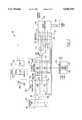
- FIG. 1is a schematic block diagram of a battery monitor according to one embodiment of the present invention.
- FIG. 2is a schematic block diagram of a battery monitor according to another embodiment of the present invention.
- a battery monitor for monitoring the battery temperature and voltage of a battery pack in an electric vehicleis merely exemplary in nature and in no way is intended to limit the invention or its application or uses. While this invention is described in connection with electric vehicles, those skilled in the art would readily recognize that the battery monitor can be incorporated to monitor batteries used with other systems.
- FIG. 1a schematic block diagram of a battery monitor 10 according to one embodiment of the present invention is shown.
- the battery monitor 10is intended to monitor the battery temperature and voltage of a series of batteries 12 positioned within a battery tub 14.
- the battery tub 14is one of three battery tubs each holding ten batteries 12 as is currently being used in the TEV minivan available from Chrysler Corporation. In this example, there would be three battery monitors each monitoring the batteries in one of the battery tubs.
- the battery monitor 10is separated into an isolated side 16 and a non-isolated side 18 at an isolation border 20.
- the isolated side 16is electrically isolated from the non-isolated side 18 to eliminate all of the common voltage sources and grounds between the sides 16 and 18 (i.e., galvanically isolated).
- the battery monitor 10can be positioned proximate to the battery tub 14 or be mounted to the battery tub 14 so as to reduce high power regions of the electric vehicle for safety and electromagnetic compatibility (EMC) purposes.
- EMCelectromagnetic compatibility
- the battery monitor 10monitors battery temperature and voltage for the batteries 12 held in the battery tub 14.
- the batteries 12are connected in series and each individual battery 12 has a voltage range of between about 0 to 20 volts.
- a series of high power input lines 22are connected to the batteries 12 to provide a signal of the voltage across each battery 12.
- a pair of high power input lines 22is connected across each battery 12 such that a single line 22 is electrically connected between each battery 12.
- a line 22is connected to a positive terminal of one battery 12 and a negative terminal of an adjacent battery 12. Therefore, one line 22 is provided to determine a positive signal of one battery 12 and a negative signal of an adjacent battery 12.
- eleven input lines 22are necessary to determine the voltage across each of the ten batteries 12.
- the battery monitor 10is mounted on or in close proximity to the battery tub 14 to reduce the length of the high power input lines 22 which are connected to the batteries 12.
- the voltages from the batteries 12 on the input lines 22are applied to an attenuator 24.
- the attenuator 24has an 8:1 ratio so as to attenuate the voltages to a voltage range of between about 0 to 2.5 volts.
- the attenuator 24includes a precision resistor divider network, well known to those skilled in the art, fabricated on a single substrate (not shown). This construction allows the attenuator 24 to be accurate since all the resistors in the network will vary evenly with any temperature changes.
- the eleven output lines from the attenuator 24include ten (10) positive (+) battery terminal lines 26 and ten (10) negative (-) battery terminal lines 28 for all of the batteries 12, as discussed above.
- the lines 26 and 28are applied to a fifteen channel differential mode analog multiplexer 30.
- Ten of the channels of the analog multiplexer 30are for the battery voltage outputs from the attenuator 24. Therefore, for each battery 12 there is a positive and negative voltage line from the attenuator 24.
- the multiplexer 30includes multiple ADG509AKN analog multiplexer chips each having four (4) input channels.
- a control signal (discussed below) applied to the multiplexer 30causes the multiplexer 30 to select a pair of inputs from the lines 26 and 28 representing a voltage across one of the batteries 12. The selected voltage is applied to a differential amplifier 32 to be buffered and amplified.
- Each switched filter 34receives a pair of voltage output lines from the attenuator 24 that represents the voltage across one of the batteries 12.
- Each switched filter 34consists of a switch 36 and a capacitor 38.
- the switch 36can be an ADG201AKN switch and the capacitor 38 can be a 10 ⁇ f capacitor.
- a control signal(discussed below) causes the switched filters 34 to be selectively switched into the battery monitor 10 by the switches 36 simultaneously to filter out battery line noise and also to allow the capacitors 38 to pre-charge.
- the filters 34are generally switched into the battery monitor 10 which causes a slower response time as a result of the capacitors 38 being charged. To obtain an instantaneous voltage measurement across the batteries 12, the filters 34 are switched out of the monitor 10.
- the filters 34are generally switched out of the monitor 10 momentarily when the electric vehicle is not operating and the batteries 12 are in a charging routine since there is less battery line noise during this condition (i.e. no current flowing from batteries 12 to power electric motor).
- the batteries 12are momentarily removed from a charging circuit (not shown) which drops the current to zero.
- the filters 34are then removed or switched out of the battery monitor 10 and an instantaneous battery voltage measurement is made. Thereafter, the charging circuit is again connected to the batteries 12 and the filters 34 are switched into the battery monitor 10. It should also be noted that the filters 34 can be switched out of the monitor 10 during normal operation of the electric vehicle to obtain an instantaneous voltage reading.
- the battery monitor 10monitors battery temperature using five (5) temperature monitors 40 one of which is shown here.
- the temperature monitors 40monitor battery temperatures for every other battery 12 in the battery tub 14 since temperatures for adjacent batteries 12 are generally similar.
- the temperature monitors 40consist of a voltage reference (Vref) and a resistor 42 in series with a filter capacitor 44.
- a temperature common signal from a known temperature source(not shown) is applied to the anode of the capacitor 44.
- a thermistor 46 connected in parallel with the filter capacitor 44is mounted proximate to the battery 12 being monitored.
- the voltage referenceis about 2.5 volts and can be provided by a stable voltage reference IC such as an AD580JT.
- the filter capacitor 44is preferably a bank of capacitors such a 10 ⁇ F tantalum capacitor in parallel with a 0.1 ⁇ F ceramic capacitor to achieve a wide filter bandwidth.
- the thermistor 46is preferably a Unicurve thermistor. The voltage drop across the five (5) thermistors 46 are applied to the multiplexer 30 along with the five (5) temperature common signals. The control signal applied to the multiplexer 30 also selects the temperature signals from the temperature monitors 40.
- the differential amplifier 32determines the voltage difference between a pair of voltage channels that are selected by the multiplexer 30.
- a serial analog signal from the amplifier 32is applied to an analog-to-digital (ND) converter 48 which converts the analog signal to a digital serial signal.
- ND converter 48could be any number of conventional analog to digital converters known in the art.
- the serial digital datais then transferred from the isolated side 16 across the border 20 by an opto-isolator 50.
- the opto-isolator 50is a combination of a photodiode and a phototransistor where an optical signal from the photodiode representing the high power digital signal is transmitted across the border 20 to be received by the phototransistor on the low voltage non-isolated side 18 of the border 20.
- the opto-isolator 50is a high speed Hewlet Packard (HP) 6N137 opto-isolators.
- HPHewlet Packard
- other opto-isolatorscould be used, as well as various other type of isolators such as transformers.
- the digital serial data provided to the non-isolated side 18 through the opto-isolator 50is applied to a microprocessor 52 through an inverter buffer 54.
- the microprocessor 52can be a Motorola 68HC05X4 processor having an "on board" MCAN (Motorola Controller Area Network) differential communication bus 56.
- the communication bus 56is a twisted pair communication bus which communicates with other modules throughout the electric vehicle. It should be noted that various other communication busses could also be utilized such as CCD, J1850 or ETHERNET.
- the battery monitor 10is controlled by address inputs 58 to the microprocessor 52.
- the inputs 58are externally jumpered in the vehicle wire harness such that multiple battery monitors 10 each monitoring a battery tub 14 in the electric vehicle can be independently communicated with.
- the microprocessor 52sends commands to the isolated side 16 through an inverted buffer 60 and an opto-isolator 62. These commands control the switching of the filters 34 into and out of the battery monitor circuit 10, as well as the selection of the specific channels of the multiplexer 30.
- a signal on the address inputs 58causes the microprocessor 52 to send a control signal to the buffer 60.
- the buffer 60sends a signal to the opto-isolator 62 to transfer the control signal from the microprocessor 52 across the border 20 in the same manner that the opto-isolator 50 transfers the transmitted battery signal across the border 20.
- the signal received by the phototransistor on the isolated side 16is then applied to the multiplexer 30 and the switched filters 34, as shown. Therefore, by providing the proper signal on the address input 58, a particular battery 12 can be monitored for voltage and temperature as selected by the multiplexer 30.
- a flyback style power supply 64is also used to maintain proper isolation.
- the power supply 64has primary windings 66 which are completely isolated from the secondary windings 68 since there is no feedback across the windings 66 and 68. Because of this, the voltage input (i.e. 5 volts) is supplied by a voltage regulator such as a TL750M05 which also powers the microprocessor 52.
- a module on the electric vehiclerequests battery voltage and/or battery temperature from the batteries 12 in a specific battery tub 14, via the communication bus 56 and the address inputs 58.
- the microprocessor 52selects the channels of the multiplexer 30 and whether or not to switch the filters 34 out of the battery monitor 10.
- the battery voltage for a specific battery 12 or the temperature for a specific battery 12 represented by the voltage drop across the thermistor 46is applied to the differential amplifier 32 and through the ND converter 48.
- the serial digital signalis transferred across the isolated border 20 by the opto-isolator 50. This signal is received by the microprocessor 52 through the buffer 54. If a battery voltage was requested, the microprocessor will transfer this data via the communication bus 56. If a battery temperature was requested, the microprocessor 52 will do a linearization of the thermistor 46 temperature curve to determine the battery temperature based on the voltage drop across the thermistor 46. This temperature would also then be transmitted via the communication bus 56.
- a battery monitor 80monitors the temperature and battery voltage for a series of batteries 82 held in a battery tub 84.
- the battery tub 84includes ten batteries 82 connected in series similar to the batteries 12 in the battery tub 14 above in FIG. 1.
- a high voltage input line 86is connected to each positive battery terminal and a high voltage input line 88 is connected to each negative battery terminal.
- FIG. 2only a single pair of high voltage input lines 86 and 88 are shown in FIG. 2, however, one skilled in the art would recognize that there would be ten (10) pairs of high voltage input lines 86 and 88 associated with the ten (10) batteries 82.
- Each pair of high voltage input lines 86 and 88are applied to a separate bank of opto-isolators 90.
- the bank of opto-isolators 90includes a first analog opto-isolator 92 connected to the positive high voltage input line 86 and a second analog opto-isolator 94 connected to the negative high voltage input line 88.
- the photodiodes in the opto-isolators 92 and 94are activated by a microprocessor 96, as will be discussed in more detail below.
- the phototransistors in the opto-isolators 92 and 94are turned on or conduct, which allows a capacitor 98 to be charged through an attenuator resistor 100.
- the resistor 100is a 100 ohm resistor and the capacitor 98 is a 0.022 ⁇ f tantalum capacitor. Since there are ten batteries 82 in the battery tub 84, one skilled in the art would recognize that there will be 10 pairs of opto-isolators 92 and 94 connected in the parallel across connection points 102 and 104.
- the microprocessor 96turns off or opens the opto-isolators 92 and 94 which causes the phototransistors in the opto-isolators 92 and 94 to stop conducting. This isolates the high voltage battery 82 from the battery monitor 80, as well as all the associated battery line voltage and noise. It should be noted that in this embodiment, the battery 82 is not galvanically isolated from the battery monitor 80 as with the embodiment shown in FIG. 1 since the battery 82 is still electrically connected through the phototransistor side of the opto-isolator 92 and 94. However, the opto-isolators 92 and 94 can be replaced with electrical relays in which case the battery 82 would be galvanically isolated from the battery monitor 80.
- the microprocessor 96then activates a second bank of opto-isolators 106 having a pair of opto-isolators 108 and 110.
- the photodiodes in the opto-isolators 108 and 110transmit an optical signal such that the phototransistors in the opto-isolators 108 and 110 are turned on so that the voltage across the capacitor 98 is applied to the positive and negative terminals of a differential amplifier 112.
- the differential amplifier 112determines the voltage difference between its positive and negative input terminals and applies this analog signal to an analog-to-digital (A/D) converter 114.
- the analog signalrepresenting the attenuated battery voltage, is digitized in the analog-to-digital converter 114 and applied to the microprocessor 96 through a buffer 116.
- the microprocessor 96then sends the battery voltage to a module (not shown) requesting such information, via a communication bus 118.
- the microprocessor 96includes address inputs 120 which determines a specific address for the battery monitor 80, via jumpers in the electric vehicle wire harness. It should be noted that the microprocessor 96 is the same as the microprocessor 52, shown in FIG. 1.
- the temperatures of the batteries 82 in the battery tub 84are monitored in substantially the same way as the temperature of the batteries 12 are monitored.
- Five (5) temperature monitors 122monitor the temperature for every other battery 82 in the battery tub 84 since temperatures for adjacent batteries 82 are generally similar.
- the temperature monitor 22consists of a 2.5 volt voltage reference (Vref) and a 20 k ⁇ resistor 124 connected in series with a filter capacitor 126.
- a 10 k ⁇ thermistor 128is connected in parallel with the capacitor 126 and is positioned proximate to the battery 82 being monitored. Since the thermistor 128 is not electrically connected to the battery 82 but is merely mounted to the housing of the battery 82 there is no need to electrically isolate the signal supplied by the temperature module 122. However, this signal may also be isolated, as shown in FIG. 1.
- the voltage drop across the five (5) thermistors 128are applied to a multiplexer 130.
- the multiplexer 130is a five channel analog multiplexer similar to the multiplexer 30, shown in FIG. 1.
- the channels of the multiplexer 130are selected by the microprocessor 96, through a buffer 132.
- the voltage drop of that particular thermistor 128is applied to the positive and negative terminals across the differential amplifier 112.
- the voltage difference across the positive and negative terminals of the differential amplifier 112is determined and applied to the analog-to-digital converter 114 to digitize the signal.
- This digital signalis subsequently applied to the microprocessor 96, through the buffer 116.
- the microprocessor 96will do a linearization of the thermistor 128 temperature curve to determine the battery temperature based on the voltage drop across the thermistor 128. Again, this information will then be transmitted, via the communication bus 118.
- the battery monitor 80further includes a power supply 134 which is similar to the power supply 64 shown in FIG. 1.
- the power supply 134includes primary windings 136 and secondary windings 138 which are isolated from one another since there is no feedback across the windings 136 and 138. This allows further isolation of the high battery voltages in the batteries 82 from the vehicle electronics.
- a module on the electric vehiclewill request a battery voltage and/or a battery temperature from the batteries 82 in the battery tub 84, via the communication bus 118. If a battery voltage is requested, the microprocessor 96 will first select which bank of opto-isolators 90 to activate depending on which battery 82 is to be monitored. The microprocessor 96 will then activate the photodiodes in the opto-isolators 92 and 94, through buffers 140 and 142. This causes the phototransistors in the opto-isolators 92 and 94 to conduct thereby allowing the capacitor 98 to be charged through resistor 100.
- the microprocessor 96turns off or opens the opto-isolators 92 and 94, via the buffers 140 and 142 and simultaneously activates the photodiodes in the opto-isolators 108 and 110, via buffers 144 and 146. This allows the charge on capacitor 98 be applied to the positive and negative terminals of the differential amplifier 112. The voltage difference between the positive and negative terminals is applied to the analog-to-digital converter 114 which converts the analog signal to a serial digital signal. This signal is then forwarded to the microprocessor 96, through the buffer 116.
- the microprocessor 96will select a particular battery to be monitored by selecting the particular channel from the multiplexer 130.
- the voltage drop across the thermistor 128 attached to the selected battery 82will be transferred through the multiplexer 130 and applied to the positive and negative terminals of the differential amplifier 112.
- This analog signalwill then be digitized in the analog-to-digital converter 114 and applied to the microprocessor 96, via the buffer 116.
- the microprocessor 96will do a linearization of the thermistor 128 temperature curve to determine the battery temperature based on the voltage drop across the thermistor 128. This temperature will then be transmitted, via the communication bus 118.
Landscapes
- Engineering & Computer Science (AREA)
- Physics & Mathematics (AREA)
- General Physics & Mathematics (AREA)
- Life Sciences & Earth Sciences (AREA)
- Sustainable Development (AREA)
- Sustainable Energy (AREA)
- Power Engineering (AREA)
- Transportation (AREA)
- Mechanical Engineering (AREA)
- Secondary Cells (AREA)
- Charge And Discharge Circuits For Batteries Or The Like (AREA)
- Electric Propulsion And Braking For Vehicles (AREA)
Abstract
Description
Claims (17)
Priority Applications (2)
| Application Number | Priority Date | Filing Date | Title |
|---|---|---|---|
| US08/369,250US5646534A (en) | 1995-01-06 | 1995-01-06 | Battery monitor for electric vehicles |
| US08/820,749US5808469A (en) | 1995-01-06 | 1997-03-19 | Battery monitor for electric vehicles |
Applications Claiming Priority (1)
| Application Number | Priority Date | Filing Date | Title |
|---|---|---|---|
| US08/369,250US5646534A (en) | 1995-01-06 | 1995-01-06 | Battery monitor for electric vehicles |
Related Child Applications (1)
| Application Number | Title | Priority Date | Filing Date |
|---|---|---|---|
| US08/820,749DivisionUS5808469A (en) | 1995-01-06 | 1997-03-19 | Battery monitor for electric vehicles |
Publications (1)
| Publication Number | Publication Date |
|---|---|
| US5646534Atrue US5646534A (en) | 1997-07-08 |
Family
ID=23454729
Family Applications (2)
| Application Number | Title | Priority Date | Filing Date |
|---|---|---|---|
| US08/369,250Expired - LifetimeUS5646534A (en) | 1995-01-06 | 1995-01-06 | Battery monitor for electric vehicles |
| US08/820,749Expired - LifetimeUS5808469A (en) | 1995-01-06 | 1997-03-19 | Battery monitor for electric vehicles |
Family Applications After (1)
| Application Number | Title | Priority Date | Filing Date |
|---|---|---|---|
| US08/820,749Expired - LifetimeUS5808469A (en) | 1995-01-06 | 1997-03-19 | Battery monitor for electric vehicles |
Country Status (1)
| Country | Link |
|---|---|
| US (2) | US5646534A (en) |
Cited By (35)
| Publication number | Priority date | Publication date | Assignee | Title |
|---|---|---|---|---|
| US5712568A (en)* | 1995-09-05 | 1998-01-27 | Ford Motor Company | Battery voltage measurement system |
| US5869950A (en)* | 1997-10-30 | 1999-02-09 | Lockheed Martin Corp. | Method for equalizing the voltage of traction battery modules of a hybrid electric vehicle |
| US5959435A (en)* | 1996-10-31 | 1999-09-28 | Nec Corporation | Method and system for monitoring battery |
| US6062899A (en)* | 1998-09-15 | 2000-05-16 | Chrysler Corporation | Digital verification of battery cable connection to power distribution module |
| US6076964A (en)* | 1998-11-11 | 2000-06-20 | Chrysler Corporation | Prediction of internal temperature of a battery using a non-linear dynamic model |
| US6166549A (en)* | 1998-12-31 | 2000-12-26 | Daimlerchrysler Corporation | Electronic circuit for measuring series connected electrochemical cell voltages |
| US6175303B1 (en) | 1999-04-22 | 2001-01-16 | Daimlerchrysler Corporation | Electric vehicle torque-o-meter |
| US6310408B1 (en)* | 1997-08-05 | 2001-10-30 | Siemens Aktiengesellschaft | System for transmitting data in a motor vehicle |
| US6313637B1 (en)* | 1997-11-20 | 2001-11-06 | Denso Corporation | Voltage detecting device for set battery |
| US6362627B1 (en)* | 1998-03-06 | 2002-03-26 | Matsushita Electric Industrial Co., Ltd. | Voltage measuring instrument with flying capacitor |
| US20030002681A1 (en)* | 1996-02-22 | 2003-01-02 | Lars-Berno Fredriksson | Device in a system operating with CAN-protocol and in a control and/or supervision system |
| WO2003003035A1 (en)* | 2001-06-29 | 2003-01-09 | Enova Systems | Accurate voltage measurement system using relay isolated circuits |
| US6549014B1 (en) | 2002-02-15 | 2003-04-15 | Power Designers, Llc | Battery monitoring method and apparatus |
| EP0992811A3 (en)* | 1998-10-06 | 2003-04-23 | Hitachi, Ltd. | Battery apparatus and control system therefor |
| US20050110464A1 (en)* | 2003-11-25 | 2005-05-26 | Baker Howard S. | Fuel cell voltage monitoring system |
| US20050127918A1 (en)* | 2003-12-12 | 2005-06-16 | Kutkut Nasser H. | Activity-based battery monitor with a universal current measuring apparatus |
| WO2005109600A1 (en)* | 2004-05-12 | 2005-11-17 | Arbarr Electronics Limited | System for monitoring cell voltage of a serial connection of battery cells |
| WO2009013464A1 (en)* | 2007-07-20 | 2009-01-29 | Frazer-Nash Technology Limited | Battery management |
| US20090174353A1 (en)* | 2007-11-20 | 2009-07-09 | Aisin Aw Co., Ltd. | Motor control device |
| US7646173B1 (en)* | 2004-03-17 | 2010-01-12 | The United States Of America As Represented By The Secretary Of Navy | Battery safety monitor system |
| DE112009002599T5 (en) | 2008-10-27 | 2012-12-06 | Sessions Pharmaceuticals Inc. | Fluid-extracting wound dressing |
| CN103158575A (en)* | 2011-12-19 | 2013-06-19 | 福特全球技术公司 | Battery pack distributed isolation detection circuitry |
| US20130307551A1 (en)* | 2012-05-15 | 2013-11-21 | Renesas Electronics Corporation | Semiconductor device and voltage measuring device |
| CN103837832A (en)* | 2012-11-21 | 2014-06-04 | 赵元雷 | Electric vehicle residual electricity gauge formed by transforming fuel-powered vehicle fuel gauge |
| US9014888B2 (en) | 2011-07-21 | 2015-04-21 | Saturna Green Systems Inc. | Vehicle communication, analysis and operation system |
| US9058578B2 (en) | 2010-12-24 | 2015-06-16 | Martin Kelly Jones | Systems and methods for battery remediation in connection with an electric powered mobiel thing (EPMT) |
| US20150280467A1 (en)* | 2012-10-03 | 2015-10-01 | Kawasaki Jukogyo Kabushiki Kaisha | Electric Vehicle, and Battery Pack |
| CN106443274A (en)* | 2016-10-31 | 2017-02-22 | 北京新能源汽车股份有限公司 | Detection device and method for high-voltage system of electric automobile |
| EP3246718A4 (en)* | 2015-06-16 | 2018-03-14 | LG Chem, Ltd. | Transformation relay and battery voltage measurement system using same |
| US9977083B2 (en) | 2016-05-17 | 2018-05-22 | Ford Global Technologies, Llc | Switched high-voltage sampling circuit for electric vehicles |
| CN108539814A (en)* | 2018-04-19 | 2018-09-14 | 他悦蓉 | Batteries of electric automobile is grouped multitap charging method and system |
| US10106049B2 (en) | 2016-05-18 | 2018-10-23 | Nxp Usa, Inc. | Battery monitoring device |
| US10365332B2 (en)* | 2012-11-02 | 2019-07-30 | Analog Devices Global Unlimited Company | System and method to reduce data handling on lithium ion battery monitors |
| JP2021034266A (en)* | 2019-08-27 | 2021-03-01 | 本田技研工業株式会社 | Battery voltage control device and electric vehicle |
| WO2023034034A1 (en)* | 2021-09-02 | 2023-03-09 | Deltran Operations Usa, Inc. | Systems and methods for detecting both vehicle battery connection and vehicle battery polarity using a single sensor circuit |
Families Citing this family (184)
| Publication number | Priority date | Publication date | Assignee | Title |
|---|---|---|---|---|
| US6331762B1 (en) | 1997-11-03 | 2001-12-18 | Midtronics, Inc. | Energy management system for automotive vehicle |
| US8198900B2 (en) | 1996-07-29 | 2012-06-12 | Midtronics, Inc. | Automotive battery charging system tester |
| US6633165B2 (en) | 1997-11-03 | 2003-10-14 | Midtronics, Inc. | In-vehicle battery monitor |
| US6566883B1 (en) | 1999-11-01 | 2003-05-20 | Midtronics, Inc. | Electronic battery tester |
| US6081098A (en) | 1997-11-03 | 2000-06-27 | Midtronics, Inc. | Method and apparatus for charging a battery |
| US6885195B2 (en) | 1996-07-29 | 2005-04-26 | Midtronics, Inc. | Method and apparatus for auditing a battery test |
| US6914413B2 (en) | 1996-07-29 | 2005-07-05 | Midtronics, Inc. | Alternator tester with encoded output |
| US7003410B2 (en) | 1996-07-29 | 2006-02-21 | Midtronics, Inc. | Electronic battery tester with relative test output |
| US6445158B1 (en) | 1996-07-29 | 2002-09-03 | Midtronics, Inc. | Vehicle electrical system tester with encoded output |
| US6329793B1 (en) | 1996-07-29 | 2001-12-11 | Midtronics, Inc. | Method and apparatus for charging a battery |
| US7246015B2 (en) | 1996-07-29 | 2007-07-17 | Midtronics, Inc. | Alternator tester |
| US6850037B2 (en) | 1997-11-03 | 2005-02-01 | Midtronics, Inc. | In-vehicle battery monitor |
| US6351102B1 (en) | 1999-04-16 | 2002-02-26 | Midtronics, Inc. | Automotive battery charging system tester |
| US8872517B2 (en) | 1996-07-29 | 2014-10-28 | Midtronics, Inc. | Electronic battery tester with battery age input |
| US7706991B2 (en) | 1996-07-29 | 2010-04-27 | Midtronics, Inc. | Alternator tester |
| US6332113B1 (en) | 1996-10-07 | 2001-12-18 | Midtronics, Inc. | Electronic battery tester |
| US5914605A (en) | 1997-01-13 | 1999-06-22 | Midtronics, Inc. | Electronic battery tester |
| JPH1118322A (en)* | 1997-06-24 | 1999-01-22 | Okamura Kenkyusho:Kk | Parallel monitor with turn-on function |
| US6871151B2 (en) | 1997-11-03 | 2005-03-22 | Midtronics, Inc. | Electronic battery tester with network communication |
| US7705602B2 (en) | 1997-11-03 | 2010-04-27 | Midtronics, Inc. | Automotive vehicle electrical system diagnostic device |
| US6586941B2 (en) | 2000-03-27 | 2003-07-01 | Midtronics, Inc. | Battery tester with databus |
| US6930485B2 (en) | 2002-03-14 | 2005-08-16 | Midtronics, Inc. | Electronic battery tester with battery failure temperature determination |
| US7688074B2 (en) | 1997-11-03 | 2010-03-30 | Midtronics, Inc. | Energy management system for automotive vehicle |
| US7126341B2 (en) | 1997-11-03 | 2006-10-24 | Midtronics, Inc. | Automotive vehicle electrical system diagnostic device |
| US7774151B2 (en) | 1997-11-03 | 2010-08-10 | Midtronics, Inc. | Wireless battery monitor |
| US8958998B2 (en) | 1997-11-03 | 2015-02-17 | Midtronics, Inc. | Electronic battery tester with network communication |
| JP3545585B2 (en)* | 1998-01-19 | 2004-07-21 | 矢崎総業株式会社 | Temperature voltage detection unit |
| US5990661A (en)* | 1998-04-30 | 1999-11-23 | Daimlerchrysler Corporation | Circulating current battery heater |
| US6259229B1 (en) | 1998-04-30 | 2001-07-10 | Daimlerchrysler Corporation | Circulating current battery heater |
| EP1032955A4 (en) | 1998-07-27 | 2002-08-07 | Gnb Technologies | Apparatus and method for carrying out diagnostic tests on batteries and for rapidly charging batteries |
| US6294896B1 (en) | 1998-09-11 | 2001-09-25 | Keith S. Champlin | Method and apparatus for measuring complex self-immitance of a general electrical element |
| US6072301A (en)* | 1998-10-20 | 2000-06-06 | Chrysler Corporation | Efficient resonant self-heating battery electric circuit |
| US6078165A (en)* | 1998-12-18 | 2000-06-20 | Chrysler Corporation | Multiplexed modular battery management system for large battery packs |
| US6882061B1 (en) | 1998-12-31 | 2005-04-19 | Daimlerchrysler Corporation | Battery self-warming mechanism using the inverter and the battery main disconnect circuitry |
| US7039533B2 (en) | 1999-04-08 | 2006-05-02 | Midtronics, Inc. | Battery test module |
| US6795782B2 (en) | 1999-04-08 | 2004-09-21 | Midtronics, Inc. | Battery test module |
| US7505856B2 (en) | 1999-04-08 | 2009-03-17 | Midtronics, Inc. | Battery test module |
| US7058525B2 (en) | 1999-04-08 | 2006-06-06 | Midtronics, Inc. | Battery test module |
| AU4333000A (en) | 1999-04-08 | 2000-11-14 | Midtronics, Inc. | Electronic battery tester |
| US6456045B1 (en) | 1999-04-16 | 2002-09-24 | Midtronics, Inc. | Integrated conductance and load test based electronic battery tester |
| US6359441B1 (en) | 1999-04-30 | 2002-03-19 | Midtronics, Inc. | Electronic battery tester |
| US6316914B1 (en) | 1999-05-05 | 2001-11-13 | Midtronics, Inc. | Testing parallel strings of storage batteries |
| US6441585B1 (en) | 1999-06-16 | 2002-08-27 | Midtronics, Inc. | Apparatus and method for testing rechargeable energy storage batteries |
| US6137269A (en) | 1999-09-01 | 2000-10-24 | Champlin; Keith S. | Method and apparatus for electronically evaluating the internal temperature of an electrochemical cell or battery |
| US6313607B1 (en) | 1999-09-01 | 2001-11-06 | Keith S. Champlin | Method and apparatus for evaluating stored charge in an electrochemical cell or battery |
| US6737831B2 (en) | 1999-09-01 | 2004-05-18 | Keith S. Champlin | Method and apparatus using a circuit model to evaluate cell/battery parameters |
| JP2001124805A (en)* | 1999-10-25 | 2001-05-11 | Yazaki Corp | Non-insulated voltage sensor |
| US6363303B1 (en) | 1999-11-01 | 2002-03-26 | Midtronics, Inc. | Alternator diagnostic system |
| US6166523A (en)* | 2000-01-11 | 2000-12-26 | Honeywell International Inc. | Smart alternator method and apparatus for optimizing fuel efficiency and monitoring batteries in an automobile |
| US6466025B1 (en) | 2000-01-13 | 2002-10-15 | Midtronics, Inc. | Alternator tester |
| JP4472820B2 (en)* | 2000-01-18 | 2010-06-02 | パナソニック株式会社 | Battery voltage detection device and detection method |
| US6225808B1 (en) | 2000-02-25 | 2001-05-01 | Midtronics, Inc. | Test counter for electronic battery tester |
| US6967484B2 (en) | 2000-03-27 | 2005-11-22 | Midtronics, Inc. | Electronic battery tester with automotive scan tool communication |
| US7598744B2 (en) | 2000-03-27 | 2009-10-06 | Midtronics, Inc. | Scan tool for electronic battery tester |
| US7398176B2 (en) | 2000-03-27 | 2008-07-08 | Midtronics, Inc. | Battery testers with secondary functionality |
| US7446536B2 (en) | 2000-03-27 | 2008-11-04 | Midtronics, Inc. | Scan tool for electronic battery tester |
| US6759849B2 (en) | 2000-03-27 | 2004-07-06 | Kevin I. Bertness | Battery tester configured to receive a removable digital module |
| US7598743B2 (en) | 2000-03-27 | 2009-10-06 | Midtronics, Inc. | Battery maintenance device having databus connection |
| US8513949B2 (en) | 2000-03-27 | 2013-08-20 | Midtronics, Inc. | Electronic battery tester or charger with databus connection |
| JP4421070B2 (en)* | 2000-04-10 | 2010-02-24 | パナソニック株式会社 | Laminate voltage measuring device |
| JP4401529B2 (en) | 2000-04-10 | 2010-01-20 | パナソニック株式会社 | Laminate voltage measuring device |
| US6304087B1 (en) | 2000-09-05 | 2001-10-16 | Midtronics, Inc. | Apparatus for calibrating electronic battery tester |
| US6906523B2 (en) | 2000-09-14 | 2005-06-14 | Midtronics, Inc. | Method and apparatus for testing cells and batteries embedded in series/parallel systems |
| JP4210030B2 (en)* | 2000-11-02 | 2009-01-14 | パナソニック株式会社 | Laminate voltage measuring device |
| US6417669B1 (en) | 2001-06-11 | 2002-07-09 | Keith S. Champlin | Suppressing interference in AC measurements of cells, batteries and other electrical elements |
| US6788025B2 (en) | 2001-06-22 | 2004-09-07 | Midtronics, Inc. | Battery charger with booster pack |
| US7501795B2 (en) | 2001-06-22 | 2009-03-10 | Midtronics Inc. | Battery charger with booster pack |
| US7479763B2 (en) | 2001-06-22 | 2009-01-20 | Midtronics, Inc. | Apparatus and method for counteracting self discharge in a storage battery |
| US7015674B2 (en) | 2001-06-22 | 2006-03-21 | Midtronics, Inc. | Booster pack with storage capacitor |
| US6469511B1 (en) | 2001-07-18 | 2002-10-22 | Midtronics, Inc. | Battery clamp with embedded environment sensor |
| US6544078B2 (en) | 2001-07-18 | 2003-04-08 | Midtronics, Inc. | Battery clamp with integrated current sensor |
| KR20030026562A (en)* | 2001-09-26 | 2003-04-03 | 현대자동차주식회사 | Battery pack fail detection device of electric vehicle |
| KR20030030541A (en)* | 2001-10-11 | 2003-04-18 | 현대자동차주식회사 | Battery management system temperature hardware & software fail detection device of electric vehicle |
| US6466026B1 (en) | 2001-10-12 | 2002-10-15 | Keith S. Champlin | Programmable current exciter for measuring AC immittance of cells and batteries |
| US6941234B2 (en) | 2001-10-17 | 2005-09-06 | Midtronics, Inc. | Query based electronic battery tester |
| US7198510B2 (en) | 2001-11-14 | 2007-04-03 | Midtronics, Inc. | Kelvin connector for a battery post |
| US6696819B2 (en) | 2002-01-08 | 2004-02-24 | Midtronics, Inc. | Battery charge control device |
| US6906522B2 (en) | 2002-03-29 | 2005-06-14 | Midtronics, Inc. | Battery tester with battery replacement output |
| US7081755B2 (en) | 2002-09-05 | 2006-07-25 | Midtronics, Inc. | Battery tester capable of predicting a discharge voltage/discharge current of a battery |
| US7723993B2 (en) | 2002-09-05 | 2010-05-25 | Midtronics, Inc. | Electronic battery tester configured to predict a load test result based on open circuit voltage, temperature, cranking size rating, and a dynamic parameter |
| US7012433B2 (en) | 2002-09-18 | 2006-03-14 | Midtronics, Inc. | Battery tester upgrade using software key |
| KR100475023B1 (en)* | 2002-10-15 | 2005-03-10 | 주식회사 백금정보통신 | Radar detector having a battery voltage indicator for automobiles |
| US6781382B2 (en) | 2002-12-05 | 2004-08-24 | Midtronics, Inc. | Electronic battery tester |
| DE10394007T5 (en) | 2002-12-31 | 2006-02-02 | Midtronics, Inc., Willowbrook | Apparatus and method for predicting the remaining discharge time of a battery |
| US6888468B2 (en) | 2003-01-22 | 2005-05-03 | Midtronics, Inc. | Apparatus and method for protecting a battery from overdischarge |
| KR100507469B1 (en)* | 2003-03-05 | 2005-08-09 | 현대자동차주식회사 | Method and apparatus for detecting voltage of a battery module of an electric vehicle |
| US6891378B2 (en) | 2003-03-25 | 2005-05-10 | Midtronics, Inc. | Electronic battery tester |
| US7408358B2 (en) | 2003-06-16 | 2008-08-05 | Midtronics, Inc. | Electronic battery tester having a user interface to configure a printer |
| US6913483B2 (en) | 2003-06-23 | 2005-07-05 | Midtronics, Inc. | Cable for electronic battery tester |
| US7319304B2 (en) | 2003-07-25 | 2008-01-15 | Midtronics, Inc. | Shunt connection to a PCB of an energy management system employed in an automotive vehicle |
| US9018958B2 (en) | 2003-09-05 | 2015-04-28 | Midtronics, Inc. | Method and apparatus for measuring a parameter of a vehicle electrical system |
| US7154276B2 (en) | 2003-09-05 | 2006-12-26 | Midtronics, Inc. | Method and apparatus for measuring a parameter of a vehicle electrical system |
| US8164343B2 (en) | 2003-09-05 | 2012-04-24 | Midtronics, Inc. | Method and apparatus for measuring a parameter of a vehicle electrical system |
| US9255955B2 (en) | 2003-09-05 | 2016-02-09 | Midtronics, Inc. | Method and apparatus for measuring a parameter of a vehicle electrical system |
| US7370195B2 (en)* | 2003-09-22 | 2008-05-06 | Microsoft Corporation | Moving principals across security boundaries without service interruption |
| US6919725B2 (en) | 2003-10-03 | 2005-07-19 | Midtronics, Inc. | Electronic battery tester/charger with integrated battery cell temperature measurement device |
| US7977914B2 (en) | 2003-10-08 | 2011-07-12 | Midtronics, Inc. | Battery maintenance tool with probe light |
| US7116109B2 (en) | 2003-11-11 | 2006-10-03 | Midtronics, Inc. | Apparatus and method for simulating a battery tester with a fixed resistance load |
| US7595643B2 (en) | 2003-11-11 | 2009-09-29 | Midtronics, Inc. | Apparatus and method for simulating a battery tester with a fixed resistance load |
| FR2862558B1 (en)* | 2003-11-20 | 2006-04-28 | Pellenc Sa | POWER AUTONOMOUS POWER PORTABLE TOOL |
| US7598699B2 (en) | 2004-02-20 | 2009-10-06 | Midtronics, Inc. | Replaceable clamp for electronic battery tester |
| JP2005265777A (en)* | 2004-03-22 | 2005-09-29 | Yazaki Corp | Switch control device and method, and voltage measuring device |
| US7119686B2 (en) | 2004-04-13 | 2006-10-10 | Midtronics, Inc. | Theft prevention device for automotive vehicle service centers |
| US7777612B2 (en) | 2004-04-13 | 2010-08-17 | Midtronics, Inc. | Theft prevention device for automotive vehicle service centers |
| US7642786B2 (en) | 2004-06-01 | 2010-01-05 | Midtronics, Inc. | Battery tester capable of identifying faulty battery post adapters |
| US7772850B2 (en) | 2004-07-12 | 2010-08-10 | Midtronics, Inc. | Wireless battery tester with information encryption means |
| US7106070B2 (en) | 2004-07-22 | 2006-09-12 | Midtronics, Inc. | Broad-band low-inductance cables for making Kelvin connections to electrochemical cells and batteries |
| US8436619B2 (en) | 2004-08-20 | 2013-05-07 | Midtronics, Inc. | Integrated tag reader and environment sensor |
| US9496720B2 (en) | 2004-08-20 | 2016-11-15 | Midtronics, Inc. | System for automatically gathering battery information |
| US8344685B2 (en) | 2004-08-20 | 2013-01-01 | Midtronics, Inc. | System for automatically gathering battery information |
| US8442877B2 (en) | 2004-08-20 | 2013-05-14 | Midtronics, Inc. | Simplification of inventory management |
| EP1662268A1 (en)* | 2004-11-30 | 2006-05-31 | "VLAAMSE INSTELLING VOOR TECHNOLOGISCH ONDERZOEK", afgekort "V.I.T.O." | System and method for measuring fuel cell voltage |
| US7710119B2 (en) | 2004-12-09 | 2010-05-04 | Midtronics, Inc. | Battery tester that calculates its own reference values |
| US7545146B2 (en) | 2004-12-09 | 2009-06-09 | Midtronics, Inc. | Apparatus and method for predicting battery capacity and fitness for service from a battery dynamic parameter and a recovery voltage differential |
| CN100561814C (en)* | 2004-12-10 | 2009-11-18 | 鸿富锦精密工业(深圳)有限公司 | Protecting circuit for electrical equipment |
| US7498767B2 (en) | 2005-02-16 | 2009-03-03 | Midtronics, Inc. | Centralized data storage of condition of a storage battery at its point of sale |
| US7382102B2 (en)* | 2005-06-13 | 2008-06-03 | Chrysler Llc | Heating of batteries using reactive power |
| US7902830B2 (en)* | 2006-05-04 | 2011-03-08 | Enerdel, Inc. | System to measure series-connected cell voltages using a flying capacitor |
| US7679369B2 (en)* | 2006-10-06 | 2010-03-16 | Enerdel, Inc. | System and method to measure series-connected cell voltages using a flying capacitor |
| US7791348B2 (en) | 2007-02-27 | 2010-09-07 | Midtronics, Inc. | Battery tester with promotion feature to promote use of the battery tester by providing the user with codes having redeemable value |
| US7808375B2 (en) | 2007-04-16 | 2010-10-05 | Midtronics, Inc. | Battery run down indicator |
| US7876071B2 (en)* | 2007-06-15 | 2011-01-25 | Avago Technologies Ecbu Ip (Singapore) Pte. Ltd. | Integrated battery voltage sensor with high voltage isolation, a battery voltage sensing system and methods therefor |
| US20080312782A1 (en) | 2007-06-15 | 2008-12-18 | Gene Berdichevsky | Electric vehicle communication interface |
| GB2463829B (en) | 2007-07-17 | 2012-11-21 | Midtronics Inc | Battery tester for electric vehicle |
| US9274157B2 (en) | 2007-07-17 | 2016-03-01 | Midtronics, Inc. | Battery tester for electric vehicle |
| DE102007038532A1 (en) | 2007-08-16 | 2009-02-19 | Robert Bosch Gmbh | Battery or battery pack |
| US8203345B2 (en) | 2007-12-06 | 2012-06-19 | Midtronics, Inc. | Storage battery and battery tester |
| CN101442211B (en)* | 2008-07-08 | 2012-08-22 | 奇瑞汽车股份有限公司 | Monitoring device and monitoring methods for distributed battery management system |
| CN101685140A (en)* | 2008-09-24 | 2010-03-31 | 三科电器有限公司 | Accumulator routing inspection circuit |
| CN101509960A (en)* | 2008-11-20 | 2009-08-19 | 奇瑞汽车股份有限公司 | Battery voltage and temperature monitoring device |
| EP2259079A1 (en)* | 2009-05-27 | 2010-12-08 | Belenos Clean Power Holding AG | System for measuring the voltage of the cells of a fuel cell |
| US9127987B2 (en) | 2009-06-30 | 2015-09-08 | Greenlight Innovation Corporation | Channel, system and method for monitoring voltages |
| TWI404962B (en)* | 2009-11-26 | 2013-08-11 | Stl Technology Co Ltd | Battery health monitoring system |
| US9588185B2 (en) | 2010-02-25 | 2017-03-07 | Keith S. Champlin | Method and apparatus for detecting cell deterioration in an electrochemical cell or battery |
| WO2011109343A2 (en) | 2010-03-03 | 2011-09-09 | Midtronics, Inc. | Monitor for front terminal batteries |
| US9229062B2 (en) | 2010-05-27 | 2016-01-05 | Midtronics, Inc. | Electronic storage battery diagnostic system |
| US20110300416A1 (en) | 2010-06-03 | 2011-12-08 | Bertness Kevin I | Battery pack maintenance for electric vehicle |
| US10046649B2 (en) | 2012-06-28 | 2018-08-14 | Midtronics, Inc. | Hybrid and electric vehicle battery pack maintenance device |
| US8738309B2 (en) | 2010-09-30 | 2014-05-27 | Midtronics, Inc. | Battery pack maintenance for electric vehicles |
| US11740294B2 (en) | 2010-06-03 | 2023-08-29 | Midtronics, Inc. | High use battery pack maintenance |
| US9419311B2 (en) | 2010-06-18 | 2016-08-16 | Midtronics, Inc. | Battery maintenance device with thermal buffer |
| US9083196B2 (en) | 2010-07-30 | 2015-07-14 | Byd Company Limited | Circuits and methods for heating batteries in parallel using resonance components in series |
| US8941358B2 (en) | 2010-07-30 | 2015-01-27 | Byd Company Limited | Heating circuits and methods based on battery discharging and charging using resonance components in series and freewheeling circuit components |
| CN201936967U (en) | 2010-07-30 | 2011-08-17 | 比亚迪股份有限公司 | Heating circuit of battery |
| US8947049B2 (en) | 2010-07-30 | 2015-02-03 | Byd Company Limited | Battery heating circuits and methods using voltage inversion and freewheeling circuit components |
| CN102074754B (en)* | 2010-12-23 | 2012-05-02 | 比亚迪股份有限公司 | battery heating circuit |
| US9209644B2 (en) | 2010-07-30 | 2015-12-08 | Byd Company Limited | Circuits and methods for heating batteries in series using resonance components in series |
| US9120394B2 (en) | 2010-07-30 | 2015-09-01 | Byd Company Limited | Battery heating circuits and methods based on battery discharging and charging using resonance components in series and multiple charge storage components |
| US9160041B2 (en) | 2010-07-30 | 2015-10-13 | Byd Company Limited | Battery heating circuits and methods using resonance components in series and bridging charge storage components |
| WO2012013065A1 (en) | 2010-07-30 | 2012-02-02 | Byd Company Limited | Battery heating circuit |
| US8994332B2 (en) | 2010-07-30 | 2015-03-31 | Byd Company Limited | Battery heating circuits and methods using voltage inversion based on predetermined conditions |
| US9214706B2 (en) | 2010-07-30 | 2015-12-15 | Byd Company Limited | Battery heating circuits and methods using resonance components in series based on charge balancing |
| US9201120B2 (en) | 2010-08-12 | 2015-12-01 | Midtronics, Inc. | Electronic battery tester for testing storage battery |
| DE102010041049A1 (en)* | 2010-09-20 | 2012-03-22 | Sb Limotive Company Ltd. | Battery system and method for determining battery module voltages |
| CN102074752B (en) | 2010-12-23 | 2012-07-04 | 比亚迪股份有限公司 | Heating circuit of battery |
| US9065293B2 (en) | 2010-12-23 | 2015-06-23 | Byd Company Limited | Battery heating circuits and methods using transformers |
| CN102310829B (en)* | 2011-09-06 | 2012-12-26 | 浙江万安科技股份有限公司 | Emergency safe disengagement device for power battery of electric automobile |
| DE102011085787A1 (en) | 2011-11-04 | 2013-05-08 | Sb Limotive Company Ltd. | Battery management unit with a variety of monitoring IC chips |
| WO2013070850A2 (en) | 2011-11-10 | 2013-05-16 | Midtronics, Inc. | Battery pack tester |
| US11325479B2 (en) | 2012-06-28 | 2022-05-10 | Midtronics, Inc. | Hybrid and electric vehicle battery maintenance device |
| US9851411B2 (en) | 2012-06-28 | 2017-12-26 | Keith S. Champlin | Suppressing HF cable oscillations during dynamic measurements of cells and batteries |
| US9244100B2 (en) | 2013-03-15 | 2016-01-26 | Midtronics, Inc. | Current clamp with jaw closure detection |
| US9312575B2 (en) | 2013-05-16 | 2016-04-12 | Midtronics, Inc. | Battery testing system and method |
| US10843574B2 (en) | 2013-12-12 | 2020-11-24 | Midtronics, Inc. | Calibration and programming of in-vehicle battery sensors |
| CN103738189B (en)* | 2014-01-15 | 2016-04-13 | 广东亿纬赛恩斯新能源系统有限公司 | Safety electric vehicle and control method thereof |
| EP2897229A1 (en) | 2014-01-16 | 2015-07-22 | Midtronics, Inc. | Battery clamp with endoskeleton design |
| US10473555B2 (en) | 2014-07-14 | 2019-11-12 | Midtronics, Inc. | Automotive maintenance system |
| US10222397B2 (en) | 2014-09-26 | 2019-03-05 | Midtronics, Inc. | Cable connector for electronic battery tester |
| US10033213B2 (en) | 2014-09-30 | 2018-07-24 | Johnson Controls Technology Company | Short circuit wake-up system and method for automotive battery while in key-off position |
| WO2016123075A1 (en) | 2015-01-26 | 2016-08-04 | Midtronics, Inc. | Alternator tester |
| US9966676B2 (en) | 2015-09-28 | 2018-05-08 | Midtronics, Inc. | Kelvin connector adapter for storage battery |
| US10608353B2 (en) | 2016-06-28 | 2020-03-31 | Midtronics, Inc. | Battery clamp |
| US12320857B2 (en) | 2016-10-25 | 2025-06-03 | Midtronics, Inc. | Electrical load for electronic battery tester and electronic battery tester including such electrical load |
| US11054480B2 (en) | 2016-10-25 | 2021-07-06 | Midtronics, Inc. | Electrical load for electronic battery tester and electronic battery tester including such electrical load |
| US11513160B2 (en) | 2018-11-29 | 2022-11-29 | Midtronics, Inc. | Vehicle battery maintenance device |
| US11566972B2 (en) | 2019-07-31 | 2023-01-31 | Midtronics, Inc. | Tire tread gauge using visual indicator |
| US11545839B2 (en) | 2019-11-05 | 2023-01-03 | Midtronics, Inc. | System for charging a series of connected batteries |
| US11668779B2 (en) | 2019-11-11 | 2023-06-06 | Midtronics, Inc. | Hybrid and electric vehicle battery pack maintenance device |
| US11474153B2 (en) | 2019-11-12 | 2022-10-18 | Midtronics, Inc. | Battery pack maintenance system |
| DE102020216599A1 (en) | 2019-12-31 | 2021-07-01 | Midtronics, Inc. | Intelligent module interface for a battery maintenance device |
| US11973202B2 (en) | 2019-12-31 | 2024-04-30 | Midtronics, Inc. | Intelligent module interface for battery maintenance device |
| US11486930B2 (en) | 2020-01-23 | 2022-11-01 | Midtronics, Inc. | Electronic battery tester with battery clamp storage holsters |
| US12330513B2 (en) | 2022-02-14 | 2025-06-17 | Midtronics, Inc. | Battery maintenance device with high voltage connector |
| US12392833B2 (en) | 2022-05-09 | 2025-08-19 | Midtronics, Inc. | Electronic battery tester |
Citations (12)
| Publication number | Priority date | Publication date | Assignee | Title |
|---|---|---|---|---|
| US3307101A (en)* | 1962-12-10 | 1967-02-28 | Motorola Inc | Storage battery condition indicator with temperature and load current compensation |
| US4360766A (en)* | 1978-09-19 | 1982-11-23 | Bogardus Jr Carl R | Multi-battery power supply for DC motors |
| US4484140A (en)* | 1982-04-23 | 1984-11-20 | The United States Of America As Represented By The Secretary Of The Navy | Battery scanning system |
| US4590430A (en)* | 1982-12-13 | 1986-05-20 | Electricite De France (Service National) | Apparatus for monitoring cell capacity in a storage battery |
| US4633418A (en)* | 1984-07-11 | 1986-12-30 | The United States Of America As Represented By The Secretary Of The Air Force | Battery control and fault detection method |
| US4931738A (en)* | 1989-01-27 | 1990-06-05 | Kaufel Group, Ltd. | Battery monitoring system of cell groups and display |
| US5111132A (en)* | 1989-04-18 | 1992-05-05 | Sanshin Kogyo Kabushiki Kaisha | Battery charging system for marine propulsion unit |
| US5170124A (en)* | 1990-06-08 | 1992-12-08 | Minister Of National Defence Of Her Majesty's Canadian Government | Method and apparatus for monitoring fuel cell performance |
| US5250904A (en)* | 1991-08-08 | 1993-10-05 | Advanced Power Technology Inc. | Device for predicting imminent failure of a stationary lead acid battery in a float mode |
| US5270946A (en)* | 1988-03-30 | 1993-12-14 | Kabushiki Kaisha Toshiba | Method and apparatus for controlling selection of batteries |
| US5345392A (en)* | 1991-01-25 | 1994-09-06 | International Business Machines Corporation | Battery charge monitor for a personal computer |
| US5444378A (en)* | 1988-07-13 | 1995-08-22 | Electronic Development Inc. | Battery state of charge monitor |
Family Cites Families (7)
| Publication number | Priority date | Publication date | Assignee | Title |
|---|---|---|---|---|
| DE3020128A1 (en)* | 1980-05-27 | 1981-12-03 | Siemens AG, 1000 Berlin und 8000 München | MONITORING DEVICE FOR A CAPACITOR BATTERY ON AN AC VOLTAGE NETWORK |
| US5321627A (en)* | 1992-03-11 | 1994-06-14 | Globe-Union, Inc. | Battery monitor and method for providing operating parameters |
| US5546003A (en)* | 1994-03-07 | 1996-08-13 | Polytronics Engineering Ltd. | Multi-cell battery monitoring system with single sensor wire |
| JP3389670B2 (en)* | 1994-03-11 | 2003-03-24 | 日産自動車株式会社 | Series connection circuit of secondary battery |
| US5619417A (en)* | 1994-11-23 | 1997-04-08 | Chrysler Corporation | Battery monitoring system for an electric vehicle |
| US5705929A (en)* | 1995-05-23 | 1998-01-06 | Fibercorp. Inc. | Battery capacity monitoring system |
| US5712568A (en)* | 1995-09-05 | 1998-01-27 | Ford Motor Company | Battery voltage measurement system |
- 1995
- 1995-01-06USUS08/369,250patent/US5646534A/ennot_activeExpired - Lifetime
- 1997
- 1997-03-19USUS08/820,749patent/US5808469A/ennot_activeExpired - Lifetime
Patent Citations (12)
| Publication number | Priority date | Publication date | Assignee | Title |
|---|---|---|---|---|
| US3307101A (en)* | 1962-12-10 | 1967-02-28 | Motorola Inc | Storage battery condition indicator with temperature and load current compensation |
| US4360766A (en)* | 1978-09-19 | 1982-11-23 | Bogardus Jr Carl R | Multi-battery power supply for DC motors |
| US4484140A (en)* | 1982-04-23 | 1984-11-20 | The United States Of America As Represented By The Secretary Of The Navy | Battery scanning system |
| US4590430A (en)* | 1982-12-13 | 1986-05-20 | Electricite De France (Service National) | Apparatus for monitoring cell capacity in a storage battery |
| US4633418A (en)* | 1984-07-11 | 1986-12-30 | The United States Of America As Represented By The Secretary Of The Air Force | Battery control and fault detection method |
| US5270946A (en)* | 1988-03-30 | 1993-12-14 | Kabushiki Kaisha Toshiba | Method and apparatus for controlling selection of batteries |
| US5444378A (en)* | 1988-07-13 | 1995-08-22 | Electronic Development Inc. | Battery state of charge monitor |
| US4931738A (en)* | 1989-01-27 | 1990-06-05 | Kaufel Group, Ltd. | Battery monitoring system of cell groups and display |
| US5111132A (en)* | 1989-04-18 | 1992-05-05 | Sanshin Kogyo Kabushiki Kaisha | Battery charging system for marine propulsion unit |
| US5170124A (en)* | 1990-06-08 | 1992-12-08 | Minister Of National Defence Of Her Majesty's Canadian Government | Method and apparatus for monitoring fuel cell performance |
| US5345392A (en)* | 1991-01-25 | 1994-09-06 | International Business Machines Corporation | Battery charge monitor for a personal computer |
| US5250904A (en)* | 1991-08-08 | 1993-10-05 | Advanced Power Technology Inc. | Device for predicting imminent failure of a stationary lead acid battery in a float mode |
Cited By (49)
| Publication number | Priority date | Publication date | Assignee | Title |
|---|---|---|---|---|
| US5712568A (en)* | 1995-09-05 | 1998-01-27 | Ford Motor Company | Battery voltage measurement system |
| US7386716B2 (en)* | 1996-02-22 | 2008-06-10 | Kvaser Consultant Ab | Device in a system operating with CAN-protocol and in a control and/or supervision system |
| US20080275996A1 (en)* | 1996-02-22 | 2008-11-06 | Kvaser Consultant Ab | Device in a system operating with can-protocol and in a control and/or supervision system |
| US8713301B2 (en) | 1996-02-22 | 2014-04-29 | Xinshu Management, L.L.C. | Device in a system operating with CAN-protocol and in a control and/or supervision system |
| US20030002681A1 (en)* | 1996-02-22 | 2003-01-02 | Lars-Berno Fredriksson | Device in a system operating with CAN-protocol and in a control and/or supervision system |
| US5959435A (en)* | 1996-10-31 | 1999-09-28 | Nec Corporation | Method and system for monitoring battery |
| US6310408B1 (en)* | 1997-08-05 | 2001-10-30 | Siemens Aktiengesellschaft | System for transmitting data in a motor vehicle |
| US5869950A (en)* | 1997-10-30 | 1999-02-09 | Lockheed Martin Corp. | Method for equalizing the voltage of traction battery modules of a hybrid electric vehicle |
| US6313637B1 (en)* | 1997-11-20 | 2001-11-06 | Denso Corporation | Voltage detecting device for set battery |
| US6362627B1 (en)* | 1998-03-06 | 2002-03-26 | Matsushita Electric Industrial Co., Ltd. | Voltage measuring instrument with flying capacitor |
| US6062899A (en)* | 1998-09-15 | 2000-05-16 | Chrysler Corporation | Digital verification of battery cable connection to power distribution module |
| EP0992811A3 (en)* | 1998-10-06 | 2003-04-23 | Hitachi, Ltd. | Battery apparatus and control system therefor |
| US6076964A (en)* | 1998-11-11 | 2000-06-20 | Chrysler Corporation | Prediction of internal temperature of a battery using a non-linear dynamic model |
| US6411097B1 (en) | 1998-12-31 | 2002-06-25 | Daimlerchrysler Corporation | Electronic circuit for measuring series connected electrochemical cell voltages |
| US6166549A (en)* | 1998-12-31 | 2000-12-26 | Daimlerchrysler Corporation | Electronic circuit for measuring series connected electrochemical cell voltages |
| US6175303B1 (en) | 1999-04-22 | 2001-01-16 | Daimlerchrysler Corporation | Electric vehicle torque-o-meter |
| WO2003003035A1 (en)* | 2001-06-29 | 2003-01-09 | Enova Systems | Accurate voltage measurement system using relay isolated circuits |
| US6549014B1 (en) | 2002-02-15 | 2003-04-15 | Power Designers, Llc | Battery monitoring method and apparatus |
| US20050110464A1 (en)* | 2003-11-25 | 2005-05-26 | Baker Howard S. | Fuel cell voltage monitoring system |
| US7173429B2 (en) | 2003-12-12 | 2007-02-06 | Power Designers, Llc | Activity-based battery monitor with a universal current measuring apparatus |
| US20050127918A1 (en)* | 2003-12-12 | 2005-06-16 | Kutkut Nasser H. | Activity-based battery monitor with a universal current measuring apparatus |
| US7646173B1 (en)* | 2004-03-17 | 2010-01-12 | The United States Of America As Represented By The Secretary Of Navy | Battery safety monitor system |
| WO2005109600A1 (en)* | 2004-05-12 | 2005-11-17 | Arbarr Electronics Limited | System for monitoring cell voltage of a serial connection of battery cells |
| WO2009013464A1 (en)* | 2007-07-20 | 2009-01-29 | Frazer-Nash Technology Limited | Battery management |
| US8093852B2 (en)* | 2007-11-20 | 2012-01-10 | Aisin Aw Co., Ltd. | Motor control device |
| US20090174353A1 (en)* | 2007-11-20 | 2009-07-09 | Aisin Aw Co., Ltd. | Motor control device |
| DE112009002599T5 (en) | 2008-10-27 | 2012-12-06 | Sessions Pharmaceuticals Inc. | Fluid-extracting wound dressing |
| US9058578B2 (en) | 2010-12-24 | 2015-06-16 | Martin Kelly Jones | Systems and methods for battery remediation in connection with an electric powered mobiel thing (EPMT) |
| US9014888B2 (en) | 2011-07-21 | 2015-04-21 | Saturna Green Systems Inc. | Vehicle communication, analysis and operation system |
| US9404956B2 (en)* | 2011-12-19 | 2016-08-02 | Ford Global Technologies, Llc | Vehicle with selectable battery pack isolation detection circuitry using precision resistors |
| CN103158575A (en)* | 2011-12-19 | 2013-06-19 | 福特全球技术公司 | Battery pack distributed isolation detection circuitry |
| US20130154656A1 (en)* | 2011-12-19 | 2013-06-20 | Ford Global Technologies, Llc | Battery pack distributed isolation detection circuitry |
| CN103158575B (en)* | 2011-12-19 | 2017-03-01 | 福特全球技术公司 | Battery distribution type insulation detecting circuit |
| US20130307551A1 (en)* | 2012-05-15 | 2013-11-21 | Renesas Electronics Corporation | Semiconductor device and voltage measuring device |
| US9821882B2 (en) | 2012-10-03 | 2017-11-21 | Kawasaki Jukogyo Kabushiki Kaisha | Assembling method and assembling management method of electric vehicle |
| US10259530B2 (en) | 2012-10-03 | 2019-04-16 | Kawasaki Jukogyo Kabushiki Kaisha | Assembling management system of electric vehicle and assembling method of electric vehicle |
| US20150280467A1 (en)* | 2012-10-03 | 2015-10-01 | Kawasaki Jukogyo Kabushiki Kaisha | Electric Vehicle, and Battery Pack |
| US9840306B2 (en)* | 2012-10-03 | 2017-12-12 | Kawasaki Jukogyo Kabushiki Kaisha | Electric vehicle, and battery pack |
| US10365332B2 (en)* | 2012-11-02 | 2019-07-30 | Analog Devices Global Unlimited Company | System and method to reduce data handling on lithium ion battery monitors |
| CN103837832A (en)* | 2012-11-21 | 2014-06-04 | 赵元雷 | Electric vehicle residual electricity gauge formed by transforming fuel-powered vehicle fuel gauge |
| US10365333B2 (en)* | 2015-06-16 | 2019-07-30 | Lg Chem, Ltd. | Transformation relay and battery voltage measurement system using same |
| EP3246718A4 (en)* | 2015-06-16 | 2018-03-14 | LG Chem, Ltd. | Transformation relay and battery voltage measurement system using same |
| US9977083B2 (en) | 2016-05-17 | 2018-05-22 | Ford Global Technologies, Llc | Switched high-voltage sampling circuit for electric vehicles |
| US10106049B2 (en) | 2016-05-18 | 2018-10-23 | Nxp Usa, Inc. | Battery monitoring device |
| CN106443274A (en)* | 2016-10-31 | 2017-02-22 | 北京新能源汽车股份有限公司 | Detection device and method for high-voltage system of electric automobile |
| CN108539814A (en)* | 2018-04-19 | 2018-09-14 | 他悦蓉 | Batteries of electric automobile is grouped multitap charging method and system |
| JP2021034266A (en)* | 2019-08-27 | 2021-03-01 | 本田技研工業株式会社 | Battery voltage control device and electric vehicle |
| JP7075914B2 (en) | 2019-08-27 | 2022-05-26 | 本田技研工業株式会社 | Battery voltage controller and electric vehicle |
| WO2023034034A1 (en)* | 2021-09-02 | 2023-03-09 | Deltran Operations Usa, Inc. | Systems and methods for detecting both vehicle battery connection and vehicle battery polarity using a single sensor circuit |
Also Published As
| Publication number | Publication date |
|---|---|
| US5808469A (en) | 1998-09-15 |
Similar Documents
| Publication | Publication Date | Title |
|---|---|---|
| US5646534A (en) | Battery monitor for electric vehicles | |
| US6462510B1 (en) | Battery voltage detector | |
| US8666687B2 (en) | Battery pack control apparatus | |
| US5652498A (en) | Charge and discharge monitoring device for serially connected electric storage cells | |
| EP0858689B1 (en) | System for equalizing the level of charge in batteries | |
| US5670861A (en) | Battery energy monitoring circuits | |
| US5677613A (en) | Method of regulating the charging of a set of electrical storage cells, and a facility implementing the method | |
| US6078165A (en) | Multiplexed modular battery management system for large battery packs | |
| EP0598798B1 (en) | Interface unit to detect communication signals | |
| US20040164706A1 (en) | Battery management unit, system and method | |
| US7554291B2 (en) | Battery control system for a chargeable-and-dischargeable power supply system | |
| JP3395952B2 (en) | Voltage detector for assembled batteries for electric vehicles | |
| US11951870B2 (en) | Battery monitoring apparatus | |
| JPH0771380B2 (en) | Device for powering a computer in a car | |
| US20150108992A1 (en) | System for monitoring state of battery pack | |
| CN104471782A (en) | Method and adjustment device for adjusting a data channel of a battery of an electrical energy store | |
| US6836721B2 (en) | Method and apparatus for providing interface to original equipment engine control computer | |
| GB2064268A (en) | Electronic Signalling Device for Connection to a Signal Transmission Line | |
| US20220123577A1 (en) | Battery control device | |
| KR102428906B1 (en) | Battery management system for integrated management of high and low voltage batterty and communication method thereof | |
| US5973410A (en) | Safety device for linking reference grounds in an integrated circuit | |
| US11280838B2 (en) | Integrated circuit and battery monitoring device | |
| EP2189322B1 (en) | Storage battery system, monitoring device and hybrid railway vehicle | |
| JP2022063286A (en) | Battery monitoring device | |
| EP4290644A1 (en) | Battery management communication system |
Legal Events
| Date | Code | Title | Description |
|---|---|---|---|
| AS | Assignment | Owner name:CHRYSLER CORPORATION Free format text:ASSIGNMENT OF ASSIGNORS INTEREST;ASSIGNOR:KOPERA, JOHN J. C.;REEL/FRAME:007402/0849 Effective date:19950309 | |
| STCF | Information on status: patent grant | Free format text:PATENTED CASE | |
| FEPP | Fee payment procedure | Free format text:PAYOR NUMBER ASSIGNED (ORIGINAL EVENT CODE: ASPN); ENTITY STATUS OF PATENT OWNER: LARGE ENTITY | |
| FPAY | Fee payment | Year of fee payment:4 | |
| FPAY | Fee payment | Year of fee payment:8 | |
| AS | Assignment | Owner name:WILMINGTON TRUST COMPANY, DELAWARE Free format text:GRANT OF SECURITY INTEREST IN PATENT RIGHTS - FIRST PRIORITY;ASSIGNOR:CHRYSLER LLC;REEL/FRAME:019773/0001 Effective date:20070803 Owner name:WILMINGTON TRUST COMPANY,DELAWARE Free format text:GRANT OF SECURITY INTEREST IN PATENT RIGHTS - FIRST PRIORITY;ASSIGNOR:CHRYSLER LLC;REEL/FRAME:019773/0001 Effective date:20070803 | |
| AS | Assignment | Owner name:WILMINGTON TRUST COMPANY, DELAWARE Free format text:GRANT OF SECURITY INTEREST IN PATENT RIGHTS - SECOND PRIORITY;ASSIGNOR:CHRYSLER LLC;REEL/FRAME:019767/0810 Effective date:20070803 Owner name:WILMINGTON TRUST COMPANY,DELAWARE Free format text:GRANT OF SECURITY INTEREST IN PATENT RIGHTS - SECOND PRIORITY;ASSIGNOR:CHRYSLER LLC;REEL/FRAME:019767/0810 Effective date:20070803 | |
| FPAY | Fee payment | Year of fee payment:12 | |
| AS | Assignment | Owner name:DAIMLERCHRYSLER CORPORATION, MICHIGAN Free format text:CHANGE OF NAME;ASSIGNOR:CHRYSLER CORPORATION;REEL/FRAME:021826/0034 Effective date:19981116 | |
| AS | Assignment | Owner name:CHRYSLER LLC, MICHIGAN Free format text:CHANGE OF NAME;ASSIGNOR:DAIMLERCHRYSLER COMPANY LLC;REEL/FRAME:021832/0233 Effective date:20070727 Owner name:DAIMLERCHRYSLER COMPANY LLC, MICHIGAN Free format text:CHANGE OF NAME;ASSIGNOR:DAIMLERCHRYSLER CORPORATION;REEL/FRAME:021832/0256 Effective date:20070329 | |
| AS | Assignment | Owner name:US DEPARTMENT OF THE TREASURY, DISTRICT OF COLUMBI Free format text:GRANT OF SECURITY INTEREST IN PATENT RIGHTS - THIR;ASSIGNOR:CHRYSLER LLC;REEL/FRAME:022259/0188 Effective date:20090102 Owner name:US DEPARTMENT OF THE TREASURY,DISTRICT OF COLUMBIA Free format text:GRANT OF SECURITY INTEREST IN PATENT RIGHTS - THIR;ASSIGNOR:CHRYSLER LLC;REEL/FRAME:022259/0188 Effective date:20090102 | |
| AS | Assignment | Owner name:CHRYSLER LLC, MICHIGAN Free format text:RELEASE BY SECURED PARTY;ASSIGNOR:US DEPARTMENT OF THE TREASURY;REEL/FRAME:022902/0164 Effective date:20090608 Owner name:CHRYSLER LLC,MICHIGAN Free format text:RELEASE BY SECURED PARTY;ASSIGNOR:US DEPARTMENT OF THE TREASURY;REEL/FRAME:022902/0164 Effective date:20090608 | |
| AS | Assignment | Owner name:CHRYSLER LLC, MICHIGAN Free format text:RELEASE OF SECURITY INTEREST IN PATENT RIGHTS - FIRST PRIORITY;ASSIGNOR:WILMINGTON TRUST COMPANY;REEL/FRAME:022910/0498 Effective date:20090604 Owner name:CHRYSLER LLC, MICHIGAN Free format text:RELEASE OF SECURITY INTEREST IN PATENT RIGHTS - SECOND PRIORITY;ASSIGNOR:WILMINGTON TRUST COMPANY;REEL/FRAME:022910/0740 Effective date:20090604 Owner name:NEW CARCO ACQUISITION LLC, MICHIGAN Free format text:ASSIGNMENT OF ASSIGNORS INTEREST;ASSIGNOR:CHRYSLER LLC;REEL/FRAME:022915/0001 Effective date:20090610 Owner name:THE UNITED STATES DEPARTMENT OF THE TREASURY, DIST Free format text:SECURITY AGREEMENT;ASSIGNOR:NEW CARCO ACQUISITION LLC;REEL/FRAME:022915/0489 Effective date:20090610 Owner name:CHRYSLER LLC,MICHIGAN Free format text:RELEASE OF SECURITY INTEREST IN PATENT RIGHTS - FIRST PRIORITY;ASSIGNOR:WILMINGTON TRUST COMPANY;REEL/FRAME:022910/0498 Effective date:20090604 Owner name:CHRYSLER LLC,MICHIGAN Free format text:RELEASE OF SECURITY INTEREST IN PATENT RIGHTS - SECOND PRIORITY;ASSIGNOR:WILMINGTON TRUST COMPANY;REEL/FRAME:022910/0740 Effective date:20090604 Owner name:NEW CARCO ACQUISITION LLC,MICHIGAN Free format text:ASSIGNMENT OF ASSIGNORS INTEREST;ASSIGNOR:CHRYSLER LLC;REEL/FRAME:022915/0001 Effective date:20090610 Owner name:THE UNITED STATES DEPARTMENT OF THE TREASURY,DISTR Free format text:SECURITY AGREEMENT;ASSIGNOR:NEW CARCO ACQUISITION LLC;REEL/FRAME:022915/0489 Effective date:20090610 | |
| AS | Assignment | Owner name:CHRYSLER GROUP LLC, MICHIGAN Free format text:CHANGE OF NAME;ASSIGNOR:NEW CARCO ACQUISITION LLC;REEL/FRAME:022919/0126 Effective date:20090610 Owner name:CHRYSLER GROUP LLC,MICHIGAN Free format text:CHANGE OF NAME;ASSIGNOR:NEW CARCO ACQUISITION LLC;REEL/FRAME:022919/0126 Effective date:20090610 | |
| AS | Assignment | Owner name:CHRYSLER GROUP LLC, MICHIGAN Free format text:RELEASE BY SECURED PARTY;ASSIGNOR:THE UNITED STATES DEPARTMENT OF THE TREASURY;REEL/FRAME:026343/0298 Effective date:20110524 Owner name:CHRYSLER GROUP GLOBAL ELECTRIC MOTORCARS LLC, NORT Free format text:RELEASE BY SECURED PARTY;ASSIGNOR:THE UNITED STATES DEPARTMENT OF THE TREASURY;REEL/FRAME:026343/0298 Effective date:20110524 | |
| AS | Assignment | Owner name:CITIBANK, N.A., NEW YORK Free format text:SECURITY AGREEMENT;ASSIGNOR:CHRYSLER GROUP LLC;REEL/FRAME:026404/0123 Effective date:20110524 | |
| AS | Assignment | Owner name:CITIBANK, N.A., NEW YORK Free format text:SECURITY AGREEMENT;ASSIGNOR:CHRYSLER GROUP LLC;REEL/FRAME:026435/0652 Effective date:20110524 | |
| AS | Assignment | Owner name:JPMORGAN CHASE BANK, N.A., ILLINOIS Free format text:SECURITY AGREEMENT;ASSIGNOR:CHRYSLER GROUP LLC;REEL/FRAME:032384/0640 Effective date:20140207 | |
| AS | Assignment | Owner name:FCA US LLC, FORMERLY KNOWN AS CHRYSLER GROUP LLC, Free format text:RELEASE OF SECURITY INTEREST RELEASING SECOND-LIEN SECURITY INTEREST PREVIOUSLY RECORDED AT REEL 026426 AND FRAME 0644, REEL 026435 AND FRAME 0652, AND REEL 032384 AND FRAME 0591;ASSIGNOR:CITIBANK, N.A.;REEL/FRAME:037784/0001 Effective date:20151221 | |
| AS | Assignment | Owner name:FCA US LLC (FORMERLY KNOWN AS CHRYSLER GROUP LLC), Free format text:RELEASE BY SECURED PARTY;ASSIGNOR:CITIBANK, N.A.;REEL/FRAME:042885/0255 Effective date:20170224 | |
| AS | Assignment | Owner name:FCA US LLC (FORMERLY KNOWN AS CHRYSLER GROUP LLC), Free format text:RELEASE BY SECURED PARTY;ASSIGNOR:JPMORGAN CHASE BANK, N.A.;REEL/FRAME:048177/0356 Effective date:20181113 |