US5646496A - Apparatus and method for generating digital position signals for a rotatable shaft - Google Patents
Apparatus and method for generating digital position signals for a rotatable shaftDownload PDFInfo
- Publication number
- US5646496A US5646496AUS08/619,267US61926796AUS5646496AUS 5646496 AUS5646496 AUS 5646496AUS 61926796 AUS61926796 AUS 61926796AUS 5646496 AUS5646496 AUS 5646496A
- Authority
- US
- United States
- Prior art keywords
- signals
- sine
- signal
- cosine
- electrical
- Prior art date
- Legal status (The legal status is an assumption and is not a legal conclusion. Google has not performed a legal analysis and makes no representation as to the accuracy of the status listed.)
- Expired - Lifetime
Links
- 238000000034methodMethods0.000titleclaimsabstractdescription45
- 230000005284excitationEffects0.000claimsabstractdescription28
- 230000001143conditioned effectEffects0.000claimsabstractdescription9
- 230000010363phase shiftEffects0.000claimsdescription9
- 230000003750conditioning effectEffects0.000claims2
- 238000012545processingMethods0.000abstractdescription36
- 238000012937correctionMethods0.000abstractdescription8
- 238000004364calculation methodMethods0.000abstractdescription3
- 238000001914filtrationMethods0.000abstractdescription2
- 230000008569processEffects0.000description18
- 230000006870functionEffects0.000description8
- 230000004044responseEffects0.000description7
- 238000010586diagramMethods0.000description6
- 230000003044adaptive effectEffects0.000description4
- 238000005259measurementMethods0.000description3
- 238000004804windingMethods0.000description3
- 230000004069differentiationEffects0.000description2
- 230000008859changeEffects0.000description1
- 239000004020conductorSubstances0.000description1
- 230000003247decreasing effectEffects0.000description1
- 230000001419dependent effectEffects0.000description1
- 238000013213extrapolationMethods0.000description1
- 230000008571general functionEffects0.000description1
- 238000012905input functionMethods0.000description1
- 238000003754machiningMethods0.000description1
- 230000007246mechanismEffects0.000description1
- 238000012544monitoring processMethods0.000description1
- 238000005070samplingMethods0.000description1
- 230000009131signaling functionEffects0.000description1
Images


Classifications
- G—PHYSICS
- G05—CONTROLLING; REGULATING
- G05B—CONTROL OR REGULATING SYSTEMS IN GENERAL; FUNCTIONAL ELEMENTS OF SUCH SYSTEMS; MONITORING OR TESTING ARRANGEMENTS FOR SUCH SYSTEMS OR ELEMENTS
- G05B19/00—Programme-control systems
- G05B19/02—Programme-control systems electric
- G05B19/18—Numerical control [NC], i.e. automatically operating machines, in particular machine tools, e.g. in a manufacturing environment, so as to execute positioning, movement or co-ordinated operations by means of programme data in numerical form
- G05B19/19—Numerical control [NC], i.e. automatically operating machines, in particular machine tools, e.g. in a manufacturing environment, so as to execute positioning, movement or co-ordinated operations by means of programme data in numerical form characterised by positioning or contouring control systems, e.g. to control position from one programmed point to another or to control movement along a programmed continuous path
- G05B19/33—Numerical control [NC], i.e. automatically operating machines, in particular machine tools, e.g. in a manufacturing environment, so as to execute positioning, movement or co-ordinated operations by means of programme data in numerical form characterised by positioning or contouring control systems, e.g. to control position from one programmed point to another or to control movement along a programmed continuous path using an analogue measuring device
- G—PHYSICS
- G08—SIGNALLING
- G08C—TRANSMISSION SYSTEMS FOR MEASURED VALUES, CONTROL OR SIMILAR SIGNALS
- G08C19/00—Electric signal transmission systems
- G08C19/38—Electric signal transmission systems using dynamo-electric devices
- G08C19/46—Electric signal transmission systems using dynamo-electric devices of which both rotor and stator carry windings
- G—PHYSICS
- G05—CONTROLLING; REGULATING
- G05B—CONTROL OR REGULATING SYSTEMS IN GENERAL; FUNCTIONAL ELEMENTS OF SUCH SYSTEMS; MONITORING OR TESTING ARRANGEMENTS FOR SUCH SYSTEMS OR ELEMENTS
- G05B2219/00—Program-control systems
- G05B2219/30—Nc systems
- G05B2219/37—Measurements
- G05B2219/37313—Derive speed from position
- G—PHYSICS
- G05—CONTROLLING; REGULATING
- G05B—CONTROL OR REGULATING SYSTEMS IN GENERAL; FUNCTIONAL ELEMENTS OF SUCH SYSTEMS; MONITORING OR TESTING ARRANGEMENTS FOR SUCH SYSTEMS OR ELEMENTS
- G05B2219/00—Program-control systems
- G05B2219/30—Nc systems
- G05B2219/37—Measurements
- G05B2219/37473—Resolver
Definitions
- This inventionrelates in general to position sensing devices for mechanisms which contain a movable member. More specifically, this invention relates to an apparatus and method for generating digital electrical signals which are representative of the angular position and rotational velocity of a rotatable shaft or similar movable mechanical component in an electromechanical servomechanism.
- a servomechanismis a control system which controls an output physical quantity in response to an input command function.
- the servomechanismis embodied as an electromechanical control system, wherein a mechanical output component is moved in accordance with an electrical input signal.
- non-mechanical output quantitiessuch as temperature, pressure, voltage, etc.
- the servomechanismincludes a closed feedback loop, wherein a signal which is representative of the current status of the output physical quantity is compared with the current input command function. If there is a difference between the two, an error signal is generated which tends to urge the output physical quantity into compliance with the input command function.
- the output mechanical componentmay be a shaft which is rotated about an axis in accordance with a predetermined electrical input position signal.
- the servomechanismcan function to rotate the shaft at a certain rotational velocity, to move the shaft to a certain rotational position, or to apply a certain torque or tension to a load in response to the electrical input signal.
- most electric motorscontain a rotor shaft which is driven to rotate about an axis relative to a stationary stator.
- Many conventional electric motorsare controlled so as to rotate the rotor shaft at a certain rotational velocity relative to the stator in response to electrical input signal.
- Such conventional electric motorscan be used to rotate the shaft at a certain rotational velocity, to move the shaft to a certain rotational position, or to apply a certain torque or tension to a load in response to the electrical input signal.
- the servomechanismusually includes a closed feedback loop, wherein a signal representative of the current status of the output physical quantity is compared with the current input command function.
- the rotational velocity or position signalcan be used in several manners to improve the operation of the electric motor. For instance, the rotational position signal can be used to increase the accuracy of the rotational velocity or angular position of the rotor shaft relative to the stator. Also, the rotational position signal can be used to control the timing of the energizations and deenergizations of the windings of the electric motor in order to increase efficiency and reduce undesirable torque ripple.
- the rotational position signal of the rotor shaft in an electric motoris usually expressed as an electrical signal, either analog or digital in nature, which is representative of the angular position of the rotor shaft relative to a predetermined starting or reference position.
- the rotational position signalcan be expressed as an analog or digital signal which is representative of a number between 0° and 360°, wherein 0° represents the predetermined starting position or reference position of the rotor shaft relative to the stator.
- a number of devicesare known in the art for generating electrical signals which are representative of the angular position of the rotor shaft relative to a predetermined starting or reference position.
- a resolveris one well known device for generating electrical signals which are representative of the relative angular position of a rotatable shaft.
- a resolveris an electromechanical transducer which generates one or more output signals which vary in magnitude with the rotational position of the rotor shaft.
- the resolvergenerates two analog electrical output signals, one which is representative of the sine of the relative angle of the rotor shaft, and the other which is representative of the cosine of the relative angle of the rotor shaft.
- the analog output signalsmay be used to control the operation of the servomechanism.
- This inventionrelates to an apparatus and method for generating digital electrical signals which are representative of the angular position and rotational velocity of a rotatable shaft or similar movable mechanical component in a servomechanism.
- the apparatusincludes a resolver which is connected to the rotatable component.
- the resolvergenerates analog electrical output signals which are representative of an excitation signal modulated by both the sine and cosine of the electrical angular position of the motor.
- the output signals from the resolverare fed to a digital signal processing circuit which, in the preferred embodiment, employs software algorithm techniques to define a plurality of tasks which are implemented sequentially to obtain the desired angular position and velocity signals.
- the sine and cosine signalsare read from the resolver through respective analog-to-digital converters.
- the sine and cosine signalsare demodulated by multiplication with the excitation signal, and the undesired higher frequency components are deleted by filtering. Then, the demodulated sine and cosine signals are conditioned to insure quadrature and to correct for amplitude and offset variations.
- an electrical angular position signal for the rotatable memberis determined by combining the demodulated and conditioned sine and cosine signals, and a correction is made for repeatable harmonic errors. A calculation is then made to determine the rotational velocity of the rotatable member. The electrical angular position signal is next corrected for velocity related errors to generate an actual electrical position signal.
- the actual electrical position signalcan be used to control commutation of the phase currents in an electric motor, which forms part of the servomechanism.
- an actual mechanical position signal for the rotatable memberis calculated. The actual mechanical position signal can be fed to a position controller circuit as a feedback signal to provide a closed loop servomechanism.
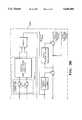
- FIG. 1is a block diagram of an electromechanical servomechanism including an apparatus and method for generating digital electrical signals which are representative of the angular position and rotational velocity of a rotatable shaft in accordance with this invention.
- FIG. 2is a flowchart illustrating the steps of the algorithm performed by the resolver-to-digital portion of the digital signal processing circuit illustrated in FIG. 1.
- FIGS. 3A and 3Bare, in combination, a block diagram which graphically illustrates the steps of the flowchart illustrated in FIG. 2.
- FIG. 1a block diagram of a servomechanism, indicated generally at 10, in accordance with this invention.
- the illustrated servomechanism 10is an electromechanical control system wherein a motor 11 is operated in accordance with an electrical input signal provided from an external position signal source 12.
- an electromechanical control systemwherein a motor 11 is operated in accordance with an electrical input signal provided from an external position signal source 12.
- this inventionwill be explained and illustrated in the embodiment of such an electromechanical servomechanism, it will be appreciated that this invention may be used in other applications wherein it is necessary or desirable to determine linear or angular position and velocity of a movable mechanical component.
- the motor 11is conventional in the art and includes a stationary stator (not shown) having an output shaft or rotor (not shown) supported for rotation therein. A plurality of windings of an electrical conductor are provided in the motor 11 so as to drive the rotor for rotation relative to the stator, preferably in either of two rotational directions.
- the rotor of the motor 11is mechanically connected to a load for movement when the motor 11 is actuated as described below.
- the position signal source 12may be embodied as any conventional circuit for generating an electrical signal which is representative of a desired position for the rotor and, thus, the load.
- the position signal source 12may be a conventional joystick device or the output of an electronic computing device.
- the desired position signal from the position signal source 12is fed to a first input of a position controller circuit 13.
- the position controller circuit 13compares the desired position signal from the position signal source 12 (which represents the desired position of the rotor) with an electrical signal fed to a second input of the position controller circuit 13 (which represents the actual position for the rotor). By comparing the desired position of the rotor with the actual position thereof, the position controller circuit 13 can determine what operation of the motor 11 (if any) is necessary to make the actual position of the rotor the same as the desired position thereof.
- the output signal from the position controller circuit 13,therefore, is an electrical signal which is representative of a desired torque command to operate the motor 11.
- the desired torque command signalcan be either analog or digital in nature.
- the structure and operation of the position controller circuit 13is conventional in the art.
- the output signal from the position controller circuit 13is fed to a digital signal processing circuit 14.
- the digital processing circuit 14can be embodied as a conventional microprocessor or other electronic programmable computational device, such as a TMS320C30 digital signal processor manufactured by Texas Instruments.
- the digital processing circuit 14includes a commutation portion 14a which is responsive to (among other things) the torque command signal from the position controller circuit 13 for generating one or more digital output signals which are representative of the desired electrical current for each of the electrical phases of the motor 11.
- the motor 11has three electrical phases.
- the commutation portion 14a of the digital processing circuit 14generates three digital output signals over three separate output lines.
- the commutation portion 14a of the digital processing circuit 14is preferably (but not necessarily) embodied as software which is executed by the microprocessor. Software for performing this commutation function is known in the art.
- the three output signals from the digital signal processing circuit 14are fed through respective conventional digital-to-analog converters 15 to a current generator circuit 16.
- the current generator circuit 16is conventional in the art and can include a current loop and power electronic circuit for generating the desired electrical current to each of the three phases of the motor 11.
- the current generator circuit 16can also include a current sensing feedback circuit (not shown) from the motor 11 for insuring that the actual electrical current supplied to the motor 11 is equal to the desired electrical current.
- the three outputs from the current generator circuit 16are respectively connected to the phase windings of the motor 11.
- the rotor of the motor 11is rotatably driven in accordance with the electrical input signal provided from the external position signal source 12.
- the illustrated servomechanism 10includes a closed feedback loop, wherein the actual mechanical position of the rotor is compared with the desired mechanical position thereof, as represented by the signal from the position signal source 12. To accomplish this, the servomechanism 10 further includes a resolver 17 which is connected to the motor 11.
- the resolver 17can be embodied as any conventional electromechanical transducer which generates one or more output signals which vary in magnitude with the rotational position of the rotor.
- an excitation signalis provided to the resolver 17 from the digital signal processing circuit 14 through a digital-to-analog converter 18 and an amplifier 19.
- the excitation signalmay, alternatively, be generated as an analog signal, in which case the digital-to-analog converter 18 would not be necessary.
- the resolver 17In response to the excitation signal and the rotation of the rotor of the motor 11 relative to the stator, the resolver 17 generates two analog electrical output signals.
- the resolver 17can be formed as a doubly salient pole variable reluctance device, including a first toothed member which is rotatable with the rotor of the motor 11 relative to a second stationary toothed member.
- a doubly salient pole variable reluctance deviceincluding a first toothed member which is rotatable with the rotor of the motor 11 relative to a second stationary toothed member.
- the rotatable member of the resolver 17is angularly aligned with the rotor of the motor 11. Regardless, the resolver 17 modulates the excitation signal by the position of the rotor of the motor 11 relative to the stator.
- one of the analog output signals from the resolver 17is representative of the sine of the angle of the rotor relative to a predetermined starting or reference position (a 0° position) on the stator.
- the other analog output signal from the resolver 17is representative of the cosine of the angle of the rotor relative to the predetermined starting or reference position.
- rotation of the rotorcauses the resolver 17 to generate analog electrical output signals which are representative of the sine and cosine of the relative electrical angular position of the resolver 17, which varies from 0° and 360°.
- the output signals from the resolver 17are fed through respective conventional anti-aliasing filters 20 and analog-to-digital converters 21 to a second input of the digital signal processing circuit 14.
- the digital processing circuit 14also includes a resolver-to-digital portion 14b which may be, but is not necessarily, embodied as software which is executed by the microprocessor mentioned above.
- the resolver-to-digital portion 14b of the digital signal processing circuit 14is responsive to the output signals from the resolver 17 for generating a plurality of digital output signals.
- a first output signal from the resolver-to-digital portion 14b of the digital processing circuit 14represents the actual electrical position of the rotor relative to the stator.
- This first signalis fed to the commutation portion 14a of the digital signal processing circuit 14 for generating the digital output signals which are representative of the desired electrical current for each of the electrical phases of the motor 11, as described above.
- the rotatable member of the resolver 17be angularly aligned with the rotor of the motor 11. If it is not, a conventional fixed offset can be introduced into the first signal to address this non-alignment.
- a second output signal from the resolver-to-digital portion 14b of the digital processing circuit 14represents the actual mechanical position of the rotor relative to the stator.
- This second signalis fed to the position controller circuit 13 to determine what operation of the motor 11 (if any) is necessary to make the actual position of the rotor the same as the desired position thereof, as also described above.
- a third output signal from the resolver-to-digital portion 14b of the digital processing circuit 14represents the rotational velocity of the rotor.
- This third signalis also fed to the commutation portion 14a of the digital signal processing circuit 14 for generating the digital output signals which are representative of the desired electrical current for each of the electrical phases of the motor 11, as described above.
- a fourth output signal generated by the resolver-to-digital portion 14b of the digital signal processing circuit 14is the excitation signal mentioned above in connection with the resolver 17. The excitation signal is fed through the digital-to-analog converter 18 and the amplifier 19 to the resolver 17.
- FIG. 2there is illustrated a flowchart of the steps of the algorithm performed by the resolver-to-digital portion 14b of the digital signal processing circuit 14 discussed above.
- FIGS. 3A and 3Bare, in combination, is a block diagram which graphically illustrates the steps of this flowchart.
- all of the steps which are disclosed in the flowchart of FIG. 2 and which are graphically represented in the block diagram of FIGS. 3A and 3Bare embodied as software which is programmed into and executed by the digital signal processing circuit 14. Nonetheless, it will be appreciated that some or all of the steps illustrated in FIG. 2, as well as some or all of the block diagram of FIGS. 3A and 3B, may be reduced into and performed by equivalent hardware components.
- the resolver-to-digital portion 14b of the digital signal processing circuit 14is provided to translate the modulated sine and cosine signals from the resolver 17 into a variety of digital output signals.
- the first step in this processis to perform input and output signal functions for the digital signal processing circuit 14. This step can be accomplished by performing two operations. The first operation is that the two output signals from the resolver 14 are read and temporarily stored by the digital signal processing circuit 14. To generate accurate information regarding the position of the rotor relative to the stator, the two output signals from the resolver 17 should be sampled simultaneously by the resolver-to-digital portion 14b of the digital signal processing circuit 14.
- the two output signals from the resolver 14are fed through the respective anti-aliasing filters 20 and the analog-to-digital converters 21 to the digital signal processing circuit 14.
- Such converters 21are preferably provided or used in conjunction with respective sample-and-hold circuits so that the two signals can be sampled simultaneously, but processed sequentially by the digital signal processing circuit 14.
- a conventional multiplexing devicecan be used in conjunction with the analog-to-digital converters 21.
- Other known analog-to-digital methodscan also be used.
- the second operation in this step of the processis to generate the excitation signal to the resolver 17, in anticipation of the next measurement of the relative rotor position.
- the digital signal processing circuit 14generates a digital signal to the digital-to-analog converter 18 which is representative of the excitation signal.
- the excitation signalis a sinusoidal signal having a frequency which is much greater (on the order of ten times greater or more) than the highest frequency of the electrical angle of the resolver 17. For example, if the highest frequency of the electrical angle of the resolver 17 is 172 cycles per second, the frequency of the excitation signal may be approximately 3200 cycles per second.
- the second step of this processis to perform a demodulation function for the two output signals from the resolver 17.
- This stepcan be accomplished by performing three operations.
- the first operation in this stepis to introduce a predetermined phase shift into the excitation signal which is to be used for demodulation. This is done to compensate for the phase shift which is introduced into the excitation signal by the combined operations of the digital-to-analog converter 18, the amplifier 19, the resolver 17, the anti-aliasing filters 20, and the analog-to-digital converter 21.
- the amount of this phase shiftcan be determined in a relatively easy manner using known techniques and may be in the range of from 10° to 15°.
- the second operation in this step of the processis to multiply each of the two output signals from the resolver 17 by the phase-shifted excitation signal.
- such multiplicationdemodulates each of the two output signals from the resolver 17 so as to recover the signals which were used by the resolver 17 to modulate the excitation signal.
- such multiplicationalso generates higher frequency signal components which are extraneous with respect to the desired sine and cosine signals from the resolver 17.
- the third operation in this step of the processis to remove such extraneous higher frequency signal components. In the illustrated embodiment, wherein the entire process is performed by the digital signal processing circuit 14, the removal of the extraneous higher frequency components is done mathematically. However, it can be seen that this step is effectively the equivalent of passing each of the two multiplied signals through respective low pass filters.
- the two raw demodulated signalsmay or may not be precisely representative of true sine and cosine values for the electrical phase of the rotor of the motor 11. This is because the resolver 17 itself may introduce errors into the two output signals therefrom.
- One errorcan be an imperfect quadrature between the two signals (i.e., the sine and cosine signals are not precisely 90° out of phase from one another), which may be caused by imperfect machining or assembly of the resolver 17.
- a second errorcan be a DC offset in the two signals, which may be caused by imperfect cancellation of the even harmonics in the resolver 17.
- a third errorcan be an amplitude imbalance between the two signals, which may be caused by an unbalanced excitation of the phases of the resolver 17, unbalanced inductances between the phases of the resolver 17, or variations in the air gap of the resolver 17. Difficulties can arise in compensating for these errors because they change over a period of time, such as in response to ambient temperature variations.
- the third step of this processis to condition the two signals to insure quadrature and to correct for amplitude and offset variations.
- This stepcan be accomplished by performing two operations.
- the first operation in this stepis to insure that the two signals are in quadrature. This can be done by mathematically adding and subtracting the two raw demodulated signals from one another as follows:
- ⁇is equal to the electrical phase of the rotor of the motor 11 and ⁇ is equal to the phase difference between the two signals. From these two equations, it can be seen that even if the two signals are not in quadrature (i.e., if ⁇ 90°), the resulting signals will be in quadrature. However, the amplitudes of the signals will be changed slightly.
- the second operation in this stepis to adaptively correct for variations in the offset and amplitude of the two signals.
- the objective of this operationis to normalize the sine and cosine signals based upon updated offset and amplitude information so as to adaptively compensate for offset and amplitude drift. This can be done by defining initial conditions for offset and amplitude.
- the initial conditionscan be provided in a look-up table created or stored in the digital signal processing circuit 14 for each of the two signals and for different electrical cycles of the resolver 17.
- the initial conditionsmay be a function of resolver tooth geometry, bearing run-out, rotatable member eccentricity, and the like.
- the appropriate offset valueis subtracted from one of the present signals, the sine signal, for example. Then, a determination is made as to whether that offset corrected sine signal is equal to zero. If not, the appropriate offset value is subtracted from the other of the present signals (the cosine signal), and a similar determination is made as to whether that offset corrected cosine signal is equal to zero. If no zero crossing has occurred, the next sine and cosine signals are read and analyzed in the same manner. This process continues until it is determined that one of the signals has decreased to zero.
- the sine signalis at either a maximum or minimum value when the cosine signal is zero.
- the cosine signalis at either a maximum or minimum value when the sine signal is zero.
- the maximum and minimum valuescan be determined by other methods if desired, such as by calculating when the time derivative of the signal changes sign from positive to negative or from negative to positive.
- the disclosed methodis preferable because unlike the time derivative method, it is unaffected by changes in the rotational direction of the rotor.
- the approximations of the present value for the amplitude and the offset of the signal to be correctedcan be calculated as follows:
- the method of this inventioncontemplates that updated normalized values for the sine and cosine signals are calculated to correct for drifting in amplitude and offset.
- the above equationscan be implemented by the microprocessor contained with the digital signal processing circuit 14. However, while the above equations work well, they do require that two mathematical divisions be performed by the microprocessor of the digital signal processing circuit 14. Such mathematical divisions are relatively time consuming for most relatively inexpensive microprocessors to perform. To avoid this, it is preferable that the inverse of the present amplitude be calculated to permit a faster mathematical multiplication to be performed by the microprocessor.
- the inverse of the present amplitudecan be calculated using the following iterative technique:
- the output signals from the resolver 17have been conditioned at this point to insure perfect quadrature and to adaptively correct for variations in amplitude and offset.
- the two signalsmay not be in exact quadrature at this point because the quadrature correction process described above works precisely only if the amplitudes of the two signals are equal. In practice, the amplitudes of the two signals are usually not sufficiently close as would be desirable.
- the fourth step of this processis to repeat the third step, as described above, to correct for imperfect quadrature and to adaptively correct for variations in offset and amplitude. It has been found that by repeating these two operations of the third step a second time, the output signals from the resolver 17 are sufficiently conditioned to provide precise measurement of the relative angular position of the rotor of the motor 11.
- the third step of the process described abovemay be repeated for adaptive offset and amplitude corrections over a predetermined number of mechanical cycles or rotations of the rotatable member of the resolver 17, then fixed at the values determined at that point.
- the fourth step of the process described abovemay be repeated, but only for adaptive offset and amplitude corrections over each mechanical cycle, as opposed to each electrical cycle.
- the fifth step of this processis to determine the electrical angle of the rotor relative to the stator, using the normalized sine and cosine signals. This step can be accomplished by performing a conventional arctangent calculation, wherein the sine and cosine values are translated into an electrical angle value.
- the sixth step in this processis to correct for repeatable harmonic errors over each electrical cycle of the resolver 17 which cannot be corrected in other ways.
- This stepcan be accomplished by providing a look-up table in the memory of the microprocessor of the digital signal processing circuit 14. The value stored in the look-up table is added to the value of the electrical angle signal to correct for these harmonic errors.
- the seventh step in this processis to calculate the rotational velocity of the rotor of the motor 11.
- the rotational velocity of the rotorcan be determined using numerical differentiation techniques, such as Richardson's extrapolation. This results in the following equation:
- his the sampling interval. While this form of numerical differentiation is more noise immune than some, there is still some high frequency noise which should be filtered away.
- a simple third order Chebychev filtercan be implemented in this step. In this manner, the rotational velocity signal of the rotor of the motor 11 can be calculated and fed to the commutation portion 14a of the digital signal processing circuit 14, as described above.
- the eighth step in this processis to add a velocity phase adjustment factor to the velocity signal. This is necessary to correct for phase shifts and other factors which are dependent upon the velocity signal. This can be done by providing a simple look-up table in the digital signal processing circuit 14.
- the velocity phase adjusted signalis added to the summation of the value of the electrical angle signal and the value harmonic error correction signal.
- the resultant signalis the actual electrical position signal which, as mentioned above, can be fed to the commutation portion 14a of the digital signal processing circuit 14.
- the final step in this processis to generate the actual mechanical position signal.
- the actual mechanical position signalis generated by adding a value which is representative of which tooth or electrical cycle is currently being analyzed to the value of the actual electrical position signal. As also discussed above, the actual mechanical position signal can be fed to the position controller circuit 13.
Landscapes
- Engineering & Computer Science (AREA)
- Physics & Mathematics (AREA)
- General Physics & Mathematics (AREA)
- Human Computer Interaction (AREA)
- Manufacturing & Machinery (AREA)
- Automation & Control Theory (AREA)
- Transmission And Conversion Of Sensor Element Output (AREA)
Abstract
Description
"SIN"+"COS"=sin θ+sin (θ+φ)=2 cos (0.5φ) sin (θ+0.5φ)
"SIN"-"COS"=sin θ-sin (θ+φ)=2 sin (0.5φ) cos (θ+0.5φ)
Present Amplitude=0.5[maximum value-(-Past Amplitude)]
Present Offset=0.5[maximum value+(-Past Amplitude)].
Present Amplitude=0.5[Past Amplitude-minimum value]
Present Offset=0.5[Past Amplitude+minimum value].
Present Amplitude=0.5[Past Amplitude +|SIG|]
Present Offset=Past Offset+0.5[SIC-Past Amplitude],
y.sub.n+1 =y.sub.n [2-(x)(y.sub.n)], where →1/x as n→∞.
V=[2(θ.sub.n -θ.sub.n-1)-0.5(θ.sub.n -θ.sub.n-2)]/h
Claims (18)
Priority Applications (2)
| Application Number | Priority Date | Filing Date | Title |
|---|---|---|---|
| US08/619,267US5646496A (en) | 1994-11-08 | 1996-03-18 | Apparatus and method for generating digital position signals for a rotatable shaft |
| US08/869,456US5760562A (en) | 1994-11-08 | 1997-06-05 | Apparatus and method for generating digital position signals for a rotatable shaft |
Applications Claiming Priority (2)
| Application Number | Priority Date | Filing Date | Title |
|---|---|---|---|
| US33631794A | 1994-11-08 | 1994-11-08 | |
| US08/619,267US5646496A (en) | 1994-11-08 | 1996-03-18 | Apparatus and method for generating digital position signals for a rotatable shaft |
Related Parent Applications (1)
| Application Number | Title | Priority Date | Filing Date |
|---|---|---|---|
| US33631794AContinuation | 1994-11-08 | 1994-11-08 |
Related Child Applications (1)
| Application Number | Title | Priority Date | Filing Date |
|---|---|---|---|
| US08/869,456ContinuationUS5760562A (en) | 1994-11-08 | 1997-06-05 | Apparatus and method for generating digital position signals for a rotatable shaft |
Publications (1)
| Publication Number | Publication Date |
|---|---|
| US5646496Atrue US5646496A (en) | 1997-07-08 |
Family
ID=23315545
Family Applications (2)
| Application Number | Title | Priority Date | Filing Date |
|---|---|---|---|
| US08/619,267Expired - LifetimeUS5646496A (en) | 1994-11-08 | 1996-03-18 | Apparatus and method for generating digital position signals for a rotatable shaft |
| US08/869,456Expired - LifetimeUS5760562A (en) | 1994-11-08 | 1997-06-05 | Apparatus and method for generating digital position signals for a rotatable shaft |
Family Applications After (1)
| Application Number | Title | Priority Date | Filing Date |
|---|---|---|---|
| US08/869,456Expired - LifetimeUS5760562A (en) | 1994-11-08 | 1997-06-05 | Apparatus and method for generating digital position signals for a rotatable shaft |
Country Status (1)
| Country | Link |
|---|---|
| US (2) | US5646496A (en) |
Cited By (46)
| Publication number | Priority date | Publication date | Assignee | Title |
|---|---|---|---|---|
| WO1999034171A1 (en)* | 1997-12-24 | 1999-07-08 | Synaptics (Uk) Limited | Signal processing apparatus and method |
| WO1999035604A3 (en)* | 1998-01-09 | 1999-10-14 | Advanced Displays Corp | Synchro-to-digital conversion with windowed peak detection |
| US6084376A (en)* | 1998-06-09 | 2000-07-04 | Aspen Motion Technologies, Inc. | Low cost resolver system |
| US6320524B1 (en)* | 1999-05-31 | 2001-11-20 | Minebea Co., Ltd. | R/D converter |
| US6323790B1 (en)* | 1999-05-31 | 2001-11-27 | Minebea Co., Ltd. | R/D converter |
| US6326908B1 (en) | 1998-09-04 | 2001-12-04 | Trilogy Systems Corp | Precision position encoder using coarse position indicator |
| US6426602B1 (en)* | 1999-09-16 | 2002-07-30 | Delphi Technologies, Inc. | Minimization of motor torque ripple due to unbalanced conditions |
| US20020113571A1 (en)* | 2000-12-25 | 2002-08-22 | Fanuc Ltd. | Motor controller |
| US20030062868A1 (en)* | 2001-10-01 | 2003-04-03 | Mir Sayeed A. | Switching methodology for ground referenced voltage controlled electric machine |
| US20030111974A1 (en)* | 2001-12-04 | 2003-06-19 | Toyoda Machine Works, Ltd. | Position detector correction method and electrically-powered steering apparatus |
| US20030181999A1 (en)* | 2002-03-19 | 2003-09-25 | Spindler Kent J. | Closed-loop phase compensation controller |
| US6674789B1 (en) | 1999-09-17 | 2004-01-06 | Delphi Technologies, Inc. | Reduction of EMI through switching frequency dithering |
| US6694287B2 (en) | 2001-08-30 | 2004-02-17 | Delphi Technologies, Inc. | Phase angle diagnostics for sinusoidal controlled electric machine |
| US20040080290A1 (en)* | 2002-10-29 | 2004-04-29 | Hill Bryan H. | Method and apparatus for fine resolution brushless motor control |
| US20040112148A1 (en)* | 2002-11-27 | 2004-06-17 | Toyoda Koki Kabushiki Kaisha | Angle detection device and torque sensor incorporating angle detection device |
| US6788221B1 (en) | 1996-06-28 | 2004-09-07 | Synaptics (Uk) Limited | Signal processing apparatus and method |
| US20040233178A1 (en)* | 2001-05-21 | 2004-11-25 | Silk Christopher J | Position sensor |
| US20050021269A1 (en)* | 2003-07-24 | 2005-01-27 | Synaptics (Uk) Limited | Magnetic calibration array |
| US20050030010A1 (en)* | 2001-10-30 | 2005-02-10 | Jones Ross Peter | Sensing apparatus and method |
| US20050035836A1 (en)* | 2001-05-30 | 2005-02-17 | Sensopad Technologies Limited | Sensing apparatus and method |
| US20050171714A1 (en)* | 2002-03-05 | 2005-08-04 | Synaptics (Uk) Limited | Position sensor |
| US20050174259A1 (en)* | 2002-06-05 | 2005-08-11 | Ely David T.E. | Signal transfer method and apparatus |
| US20060119351A1 (en)* | 2002-10-16 | 2006-06-08 | Tt Electronics Technology Limited | Sensing apparatus and method |
| US20060125472A1 (en)* | 2002-10-16 | 2006-06-15 | Tt Electronics Technology Limited | Position sensing apparatus and method |
| US7109670B1 (en)* | 2005-05-25 | 2006-09-19 | Rockwell Automation Technologies, Inc. | Motor drive with velocity-second compensation |
| US20060244464A1 (en)* | 2003-02-17 | 2006-11-02 | Sensopad Limited | Sensing apparatus and method |
| US20060267528A1 (en)* | 2005-05-25 | 2006-11-30 | Rehm Thomas J | Motor drive with velocity noise filter |
| US20070035417A1 (en)* | 2005-08-11 | 2007-02-15 | Mitutoyo Corporation | Method and circuit for interpolating encoder output |
| US20070085836A1 (en)* | 2003-08-26 | 2007-04-19 | David Ely | Digitiser system |
| US20070273359A1 (en)* | 2006-02-03 | 2007-11-29 | Grupa Timothy M | Modularized servo control system |
| US20070296364A1 (en)* | 2006-02-03 | 2007-12-27 | Shoemaker Jeffrey W | Nonlinear motor control techniques |
| US20080117086A1 (en)* | 2006-10-31 | 2008-05-22 | Mitutoyo Corporation | High speed quadrature counter |
| US20080129242A1 (en)* | 2004-10-13 | 2008-06-05 | Ketao Liu | Scale factor calibration and compensation for angular position resolver |
| US20080204116A1 (en)* | 2004-08-09 | 2008-08-28 | Sensopad Limited | Sensing Apparatus And Method |
| US20120209562A1 (en)* | 2009-07-07 | 2012-08-16 | Conti Temic Microelectronic Gmbh | Assembly and method for determining an angular position |
| US8514111B1 (en) | 2012-06-04 | 2013-08-20 | The United States Of America As Represented By The Secretary Of The Navy | Hybrid digital-to-synchro converter unit |
| US8570028B2 (en) | 2007-05-10 | 2013-10-29 | Cambridge Integrated Circuits Limited | Transducer for a position sensor |
| US8797195B1 (en) | 2012-06-29 | 2014-08-05 | The United States Of America As Represented By The Secretary Of The Navy | Smart synchro generator unit |
| US9410791B2 (en) | 2010-12-24 | 2016-08-09 | Cambridge Integrated Circuits Limited | Position sensing transducer |
| US20160238409A1 (en)* | 2015-02-16 | 2016-08-18 | Visedo Oy | Device for producing a rotational position signal and a method for producing rotational position signals |
| US9470505B2 (en) | 2012-06-13 | 2016-10-18 | Cambridge Integrated Circuits Limited | Position sensing transducer |
| CN107332480A (en)* | 2017-07-25 | 2017-11-07 | 天津电气科学研究院有限公司 | A kind of universal rotation based on FPGA becomes excitation and decoding circuit |
| US10910985B2 (en) | 2018-12-03 | 2021-02-02 | Ford Global Technologies, Llc | Vehicle electric motor closed-loop position holding control |
| US10962387B2 (en)* | 2017-10-02 | 2021-03-30 | Safran Electronics & Defense | Method for measuring a displacement |
| CN113169690A (en)* | 2018-12-05 | 2021-07-23 | 海拉有限双合股份公司 | Apparatus, arrangement system and method for determining angle between rotor and stator |
| US20240369986A1 (en)* | 2021-08-23 | 2024-11-07 | Parker-Hannifin Corporation | Systems and Methods for a Resolver and Motor Control with Enhanced Speed and Direction Monitoring |
Families Citing this family (24)
| Publication number | Priority date | Publication date | Assignee | Title |
|---|---|---|---|---|
| WO2000014696A1 (en)* | 1998-09-03 | 2000-03-16 | Aspen Motion Technologies, Inc. | Closed loop control of motor position and velocity |
| WO2000014695A1 (en)* | 1998-09-03 | 2000-03-16 | Aspen Motion Technologies, Inc. | Low cost redundant resolver system |
| US6377012B1 (en)* | 1998-12-03 | 2002-04-23 | Mitsubishi Denki Kabushiki Kaisha | Servo system controller |
| US6525502B1 (en)* | 1999-09-02 | 2003-02-25 | Aspen Motion Technologies, Inc. | Closed loop control of motor position and velocity |
| US6441578B1 (en) | 1999-09-16 | 2002-08-27 | Delphi Technologies, Inc. | Method and apparatus for torque linearization in an electric power steering system |
| US6498451B1 (en) | 2000-09-06 | 2002-12-24 | Delphi Technologies, Inc. | Torque ripple free electric power steering |
| US6754610B2 (en)* | 2001-05-16 | 2004-06-22 | Raytheon Company | Digital signal processing of resolver rotor angle signals |
| DE60223898T2 (en)* | 2002-01-30 | 2008-11-27 | Continental Automotive Gmbh | Method and device for determining the rotor position of a motor by feeding a resolver signal derived from the rotor position into a single control system which serves both to trigger and to determine the resolver signal, and to a motorized vehicle equipped with such a device is |
| JP2004045286A (en)* | 2002-07-12 | 2004-02-12 | Denso Corp | Method of correcting resolver |
| US7362070B2 (en)* | 2002-11-04 | 2008-04-22 | Hamilton Sundstrand Corporation | Electric motor control system including position determination and error correction |
| JP2005091204A (en)* | 2003-09-18 | 2005-04-07 | Toyoda Mach Works Ltd | Electric power steering device |
| US8239154B2 (en)* | 2006-11-16 | 2012-08-07 | Continental Automotive Systems Us, Inc. | Method and apparatus for resolver compensation |
| US7469193B2 (en) | 2006-11-16 | 2008-12-23 | Continental Automotive Systems Us, Inc. | Method and apparatus for resolver compensation |
| JP4885245B2 (en)* | 2009-01-15 | 2012-02-29 | 日本航空電子工業株式会社 | RD converter and angle detection device |
| JP5789911B2 (en)* | 2009-10-06 | 2015-10-07 | 株式会社ジェイテクト | Rotation angle detection device and electric power steering device |
| DE102009047633B4 (en)* | 2009-12-08 | 2020-10-08 | Robert Bosch Gmbh | Method and devices for interference field compensation of sensor signals in an electric power steering system |
| DE102010035196B4 (en) | 2010-08-24 | 2023-02-23 | Volkswagen Ag | Method and device for determining a rotor angular velocity |
| CN102789242A (en)* | 2012-09-03 | 2012-11-21 | 中国科学院国家天文台南京天文光学技术研究所 | Control system for realizing nonlinear interference compensation of torsion angle of astronomical telescope |
| US9975570B2 (en)* | 2013-02-22 | 2018-05-22 | Steering Solutions Ip Holding Corporation | Velocity signal filter with reduced lag |
| RU2537514C1 (en)* | 2013-08-21 | 2015-01-10 | Открытое акционерное общество Арзамасское научно-производственное предприятие "ТЕМП-АВИА" (ОАО АНПП "ТЕМП-АВИА") | Device to integrate standby instrument integrated system orientation unit with aircraft instrumentation complex |
| US20170174085A1 (en) | 2015-12-18 | 2017-06-22 | Hamilton Sundstrand Corporation | Permanent magnet synchronous generator based direct current power generating system |
| US11646682B2 (en) | 2021-09-30 | 2023-05-09 | Rolls-Royce Corporation | Technologies for redundant shaft information feedback in multi-machine drive systems with multiple resolvers |
| US11601077B1 (en) | 2021-09-30 | 2023-03-07 | Rolls-Royce Corporation | Technologies for redundant shaft information feedback in electric machine systems including a resolver |
| US11646685B2 (en) | 2021-09-30 | 2023-05-09 | Rolls-Royce Corporation | Technologies for redundant shaft information feedback in electric machine systems having multiple resolvers |
Citations (34)
| Publication number | Priority date | Publication date | Assignee | Title |
|---|---|---|---|---|
| US3577088A (en)* | 1969-02-03 | 1971-05-04 | Us Air Force | Sine-cosine to magnitude-phase angle converter |
| US3579268A (en)* | 1968-07-09 | 1971-05-18 | Ampex | Automatic quadrature and amplitude stabilizer |
| US3688303A (en)* | 1970-06-10 | 1972-08-29 | Sperry Rand Corp | Synchro-to-digital converter |
| US3984831A (en)* | 1974-12-12 | 1976-10-05 | Control Systems Research, Inc. | Tracking digital angle encoder |
| US4281316A (en)* | 1978-08-11 | 1981-07-28 | The Singer Company | Successive approximation S/D converter with inherent quantization error centering |
| US4334272A (en)* | 1979-02-09 | 1982-06-08 | Fujitsu Fanuc Limited | Tracer control system |
| US4454458A (en)* | 1981-12-02 | 1984-06-12 | Hewlett-Packard Company | Synchronous drive for brushless DC motor |
| US4468617A (en)* | 1982-02-11 | 1984-08-28 | General Electric Company | Velocity sensor and method of producing a velocity signal |
| US4558304A (en)* | 1983-02-24 | 1985-12-10 | Texas Instruments Incorporated | Incremental encoder synchronous decode circuit |
| US4575667A (en)* | 1981-06-09 | 1986-03-11 | Fanuc Ltd | AC Motor speed control apparatus |
| US4591831A (en)* | 1984-05-08 | 1986-05-27 | Intelligent Controls, Inc. | Position angle transducer for tap changing transformers |
| US4591774A (en)* | 1981-05-21 | 1986-05-27 | Dataproducts Corporation | High performance incremental motion system using a closed loop stepping motor |
| US4623831A (en)* | 1982-10-26 | 1986-11-18 | Fanuc Ltd | Rotor position sensing apparatus for motors |
| US4712106A (en)* | 1983-12-12 | 1987-12-08 | International Cybernetics Corporation | Phase analog encoding system with compensation |
| US4733117A (en)* | 1987-04-27 | 1988-03-22 | The Superior Electric Company | Reluctance synchro/resolver |
| US4758787A (en)* | 1986-08-08 | 1988-07-19 | Renishaw Plc | Processing quadrature signals |
| US4837493A (en)* | 1985-12-18 | 1989-06-06 | Shinko Electric Co., Ltd. | System for driving drum |
| US4843291A (en)* | 1988-02-12 | 1989-06-27 | Itt Aerospace Optical, A Division Of Itt Corporation | Digital to synchro converter |
| US4847879A (en)* | 1987-03-03 | 1989-07-11 | Yamaha Corporation | Frequency sensing and control circuit |
| US4884016A (en)* | 1988-08-23 | 1989-11-28 | Aerotech, Inc. | Closed loop torque angle control of synchronous motor |
| US4933674A (en)* | 1984-06-11 | 1990-06-12 | Allen-Bradley Company, Inc. | Method and apparatus for correcting resolver errors |
| US4972186A (en)* | 1989-03-20 | 1990-11-20 | Allen-Bradley Company, Inc. | Resolver excitation circuit |
| US4989001A (en)* | 1989-04-20 | 1991-01-29 | Advanced Micro Controls, Inc. | Microcontroller based resolver-to-digital converter |
| US4992716A (en)* | 1989-08-02 | 1991-02-12 | Kollmorgen Corp. | Motor control with digital feedback |
| US5041829A (en)* | 1985-08-22 | 1991-08-20 | Muirhead Vactric Components, Ltd. | Interpolation method and shaft angle encoder |
| US5121116A (en)* | 1988-05-30 | 1992-06-09 | Fanuc Ltd. | Absolute position encoder |
| US5162798A (en)* | 1991-06-17 | 1992-11-10 | Pacific Scientific Company | Resolver to digital converter |
| US5196776A (en)* | 1989-09-06 | 1993-03-23 | Space Systems/Loral, Inc. | Waveform generator for a resolver |
| US5235406A (en)* | 1990-06-20 | 1993-08-10 | Canon Kabushiki Kaisha | Object displacement detection |
| US5347355A (en)* | 1992-01-21 | 1994-09-13 | Canon Kabushiki Kaisha | Signal processing apparatus and method, and displacement detecting apparatus using the same |
| US5451945A (en)* | 1994-02-22 | 1995-09-19 | The United States Of America As Represented By The Administrator, National Aeronautics And Space Administration | Multi-speed multi-phase resolver converter |
| US5461293A (en)* | 1993-05-12 | 1995-10-24 | Sundstrand Corporation | Rotor position detector |
| US5495163A (en)* | 1993-05-12 | 1996-02-27 | Sundstrand Corporation | Control for a brushless generator operable in generating and starting modes |
| US5495162A (en)* | 1993-05-12 | 1996-02-27 | Sundstrand Corporation | Position-and-velocity sensorless control for starter generator electrical system using generator back-EMF voltage |
- 1996
- 1996-03-18USUS08/619,267patent/US5646496A/ennot_activeExpired - Lifetime
- 1997
- 1997-06-05USUS08/869,456patent/US5760562A/ennot_activeExpired - Lifetime
Patent Citations (34)
| Publication number | Priority date | Publication date | Assignee | Title |
|---|---|---|---|---|
| US3579268A (en)* | 1968-07-09 | 1971-05-18 | Ampex | Automatic quadrature and amplitude stabilizer |
| US3577088A (en)* | 1969-02-03 | 1971-05-04 | Us Air Force | Sine-cosine to magnitude-phase angle converter |
| US3688303A (en)* | 1970-06-10 | 1972-08-29 | Sperry Rand Corp | Synchro-to-digital converter |
| US3984831A (en)* | 1974-12-12 | 1976-10-05 | Control Systems Research, Inc. | Tracking digital angle encoder |
| US4281316A (en)* | 1978-08-11 | 1981-07-28 | The Singer Company | Successive approximation S/D converter with inherent quantization error centering |
| US4334272A (en)* | 1979-02-09 | 1982-06-08 | Fujitsu Fanuc Limited | Tracer control system |
| US4591774A (en)* | 1981-05-21 | 1986-05-27 | Dataproducts Corporation | High performance incremental motion system using a closed loop stepping motor |
| US4575667A (en)* | 1981-06-09 | 1986-03-11 | Fanuc Ltd | AC Motor speed control apparatus |
| US4454458A (en)* | 1981-12-02 | 1984-06-12 | Hewlett-Packard Company | Synchronous drive for brushless DC motor |
| US4468617A (en)* | 1982-02-11 | 1984-08-28 | General Electric Company | Velocity sensor and method of producing a velocity signal |
| US4623831A (en)* | 1982-10-26 | 1986-11-18 | Fanuc Ltd | Rotor position sensing apparatus for motors |
| US4558304A (en)* | 1983-02-24 | 1985-12-10 | Texas Instruments Incorporated | Incremental encoder synchronous decode circuit |
| US4712106A (en)* | 1983-12-12 | 1987-12-08 | International Cybernetics Corporation | Phase analog encoding system with compensation |
| US4591831A (en)* | 1984-05-08 | 1986-05-27 | Intelligent Controls, Inc. | Position angle transducer for tap changing transformers |
| US4933674A (en)* | 1984-06-11 | 1990-06-12 | Allen-Bradley Company, Inc. | Method and apparatus for correcting resolver errors |
| US5041829A (en)* | 1985-08-22 | 1991-08-20 | Muirhead Vactric Components, Ltd. | Interpolation method and shaft angle encoder |
| US4837493A (en)* | 1985-12-18 | 1989-06-06 | Shinko Electric Co., Ltd. | System for driving drum |
| US4758787A (en)* | 1986-08-08 | 1988-07-19 | Renishaw Plc | Processing quadrature signals |
| US4847879A (en)* | 1987-03-03 | 1989-07-11 | Yamaha Corporation | Frequency sensing and control circuit |
| US4733117A (en)* | 1987-04-27 | 1988-03-22 | The Superior Electric Company | Reluctance synchro/resolver |
| US4843291A (en)* | 1988-02-12 | 1989-06-27 | Itt Aerospace Optical, A Division Of Itt Corporation | Digital to synchro converter |
| US5121116A (en)* | 1988-05-30 | 1992-06-09 | Fanuc Ltd. | Absolute position encoder |
| US4884016A (en)* | 1988-08-23 | 1989-11-28 | Aerotech, Inc. | Closed loop torque angle control of synchronous motor |
| US4972186A (en)* | 1989-03-20 | 1990-11-20 | Allen-Bradley Company, Inc. | Resolver excitation circuit |
| US4989001A (en)* | 1989-04-20 | 1991-01-29 | Advanced Micro Controls, Inc. | Microcontroller based resolver-to-digital converter |
| US4992716A (en)* | 1989-08-02 | 1991-02-12 | Kollmorgen Corp. | Motor control with digital feedback |
| US5196776A (en)* | 1989-09-06 | 1993-03-23 | Space Systems/Loral, Inc. | Waveform generator for a resolver |
| US5235406A (en)* | 1990-06-20 | 1993-08-10 | Canon Kabushiki Kaisha | Object displacement detection |
| US5162798A (en)* | 1991-06-17 | 1992-11-10 | Pacific Scientific Company | Resolver to digital converter |
| US5347355A (en)* | 1992-01-21 | 1994-09-13 | Canon Kabushiki Kaisha | Signal processing apparatus and method, and displacement detecting apparatus using the same |
| US5461293A (en)* | 1993-05-12 | 1995-10-24 | Sundstrand Corporation | Rotor position detector |
| US5495163A (en)* | 1993-05-12 | 1996-02-27 | Sundstrand Corporation | Control for a brushless generator operable in generating and starting modes |
| US5495162A (en)* | 1993-05-12 | 1996-02-27 | Sundstrand Corporation | Position-and-velocity sensorless control for starter generator electrical system using generator back-EMF voltage |
| US5451945A (en)* | 1994-02-22 | 1995-09-19 | The United States Of America As Represented By The Administrator, National Aeronautics And Space Administration | Multi-speed multi-phase resolver converter |
Cited By (81)
| Publication number | Priority date | Publication date | Assignee | Title |
|---|---|---|---|---|
| US6788221B1 (en) | 1996-06-28 | 2004-09-07 | Synaptics (Uk) Limited | Signal processing apparatus and method |
| US6980134B2 (en) | 1996-06-28 | 2005-12-27 | Synaptics (Uk) Limited | Signal processing apparatus and method |
| WO1999034171A1 (en)* | 1997-12-24 | 1999-07-08 | Synaptics (Uk) Limited | Signal processing apparatus and method |
| EP1308699A3 (en)* | 1997-12-24 | 2005-06-08 | Synaptics (UK) Limited | Signal processing apparatus and method |
| EP1046124A4 (en)* | 1998-01-09 | 2003-07-09 | Universal Instruments Corp | Method and apparatus for converting analog synchro signals to a signal representative of the status of a mechanical output component |
| US6222469B1 (en)* | 1998-01-09 | 2001-04-24 | Universal Avionics Systems Corporation | Synchro-to-digital conversion with windowed peak determination |
| US6075472A (en)* | 1998-01-09 | 2000-06-13 | Universal Avionics Systems Corporation--Instrument Division | Synchro-to-digital conversion with windowed peak determination |
| WO1999035604A3 (en)* | 1998-01-09 | 1999-10-14 | Advanced Displays Corp | Synchro-to-digital conversion with windowed peak detection |
| US6084376A (en)* | 1998-06-09 | 2000-07-04 | Aspen Motion Technologies, Inc. | Low cost resolver system |
| US6326908B1 (en) | 1998-09-04 | 2001-12-04 | Trilogy Systems Corp | Precision position encoder using coarse position indicator |
| US6320524B1 (en)* | 1999-05-31 | 2001-11-20 | Minebea Co., Ltd. | R/D converter |
| US6323790B1 (en)* | 1999-05-31 | 2001-11-27 | Minebea Co., Ltd. | R/D converter |
| US6426602B1 (en)* | 1999-09-16 | 2002-07-30 | Delphi Technologies, Inc. | Minimization of motor torque ripple due to unbalanced conditions |
| US6674789B1 (en) | 1999-09-17 | 2004-01-06 | Delphi Technologies, Inc. | Reduction of EMI through switching frequency dithering |
| US20020113571A1 (en)* | 2000-12-25 | 2002-08-22 | Fanuc Ltd. | Motor controller |
| EP1220070A3 (en)* | 2000-12-25 | 2004-04-28 | Fanuc Ltd | Motor controller with information display |
| US6822414B2 (en) | 2000-12-25 | 2004-11-23 | Fanuc Ltd. | Motor controller |
| US20040233178A1 (en)* | 2001-05-21 | 2004-11-25 | Silk Christopher J | Position sensor |
| US7511705B2 (en) | 2001-05-21 | 2009-03-31 | Synaptics (Uk) Limited | Position sensor |
| US8243033B2 (en) | 2001-05-21 | 2012-08-14 | Synaptics (Uk) Limited | Position sensor |
| US20090184940A1 (en)* | 2001-05-21 | 2009-07-23 | Synaptics (Uk) Limited | Position sensor |
| US7196604B2 (en) | 2001-05-30 | 2007-03-27 | Tt Electronics Technology Limited | Sensing apparatus and method |
| US20050035836A1 (en)* | 2001-05-30 | 2005-02-17 | Sensopad Technologies Limited | Sensing apparatus and method |
| US6694287B2 (en) | 2001-08-30 | 2004-02-17 | Delphi Technologies, Inc. | Phase angle diagnostics for sinusoidal controlled electric machine |
| US20030062868A1 (en)* | 2001-10-01 | 2003-04-03 | Mir Sayeed A. | Switching methodology for ground referenced voltage controlled electric machine |
| US7208945B2 (en) | 2001-10-30 | 2007-04-24 | Tt Electronics Technology Limited | Sensing apparatus and method |
| US20050030010A1 (en)* | 2001-10-30 | 2005-02-10 | Jones Ross Peter | Sensing apparatus and method |
| US7319319B2 (en) | 2001-10-30 | 2008-01-15 | Tt Electronics Technology Limited | Sensing apparatus and method |
| US20030111974A1 (en)* | 2001-12-04 | 2003-06-19 | Toyoda Machine Works, Ltd. | Position detector correction method and electrically-powered steering apparatus |
| US7012399B2 (en)* | 2001-12-04 | 2006-03-14 | Toyoda Machine Works, Ltd. | Position detector correction method and electrically-powered steering apparatus |
| US20050171714A1 (en)* | 2002-03-05 | 2005-08-04 | Synaptics (Uk) Limited | Position sensor |
| US7406393B2 (en) | 2002-03-05 | 2008-07-29 | Synaptics (Uk) Limited | Position sensor |
| US20030181999A1 (en)* | 2002-03-19 | 2003-09-25 | Spindler Kent J. | Closed-loop phase compensation controller |
| US6690989B2 (en)* | 2002-03-19 | 2004-02-10 | 3M Innovative Properties Company | Closed-loop phase compensation controller |
| US7907130B2 (en) | 2002-06-05 | 2011-03-15 | Synaptics (Uk) Limited | Signal transfer method and apparatus |
| US20050174259A1 (en)* | 2002-06-05 | 2005-08-11 | Ely David T.E. | Signal transfer method and apparatus |
| US7514919B2 (en) | 2002-10-16 | 2009-04-07 | Tt Electronics Technology Limited | Sensing apparatus and method |
| US20060119351A1 (en)* | 2002-10-16 | 2006-06-08 | Tt Electronics Technology Limited | Sensing apparatus and method |
| US20060125472A1 (en)* | 2002-10-16 | 2006-06-15 | Tt Electronics Technology Limited | Position sensing apparatus and method |
| US7298137B2 (en) | 2002-10-16 | 2007-11-20 | Tt Electronics Technology Limited | Position sensing apparatus and method |
| US20040080290A1 (en)* | 2002-10-29 | 2004-04-29 | Hill Bryan H. | Method and apparatus for fine resolution brushless motor control |
| US6744230B2 (en)* | 2002-10-29 | 2004-06-01 | Honeywell International Inc. | Method and apparatus for fine resolution brushless motor control |
| US6948382B2 (en) | 2002-11-27 | 2005-09-27 | Toyoda Koki Kabushiki Kaisha | Angle detection device and torque sensor incorporating angle detection device |
| EP1424264A3 (en)* | 2002-11-27 | 2004-11-10 | Toyoda Koki Kabushiki Kaisha | Angle detection device and torque sensor incorporating angle detection device |
| US20040112148A1 (en)* | 2002-11-27 | 2004-06-17 | Toyoda Koki Kabushiki Kaisha | Angle detection device and torque sensor incorporating angle detection device |
| US20060244464A1 (en)* | 2003-02-17 | 2006-11-02 | Sensopad Limited | Sensing apparatus and method |
| US7205775B2 (en) | 2003-02-17 | 2007-04-17 | Sensopad Limited | Sensing apparatus and method |
| US7133793B2 (en) | 2003-07-24 | 2006-11-07 | Synaptics (Uk) Limited | Magnetic calibration array |
| US20050021269A1 (en)* | 2003-07-24 | 2005-01-27 | Synaptics (Uk) Limited | Magnetic calibration array |
| US7812268B2 (en) | 2003-08-26 | 2010-10-12 | Synaptics (Uk) Limited | Digitizer system |
| US8022317B2 (en) | 2003-08-26 | 2011-09-20 | Synaptics (Uk) Limited | Digitizer system |
| US20100321338A1 (en)* | 2003-08-26 | 2010-12-23 | Synaptics (Uk) Ltd. | Digitizer system |
| US20070085836A1 (en)* | 2003-08-26 | 2007-04-19 | David Ely | Digitiser system |
| US20080204116A1 (en)* | 2004-08-09 | 2008-08-28 | Sensopad Limited | Sensing Apparatus And Method |
| US8000896B2 (en)* | 2004-10-13 | 2011-08-16 | The Boeing Company | Scale factor calibration and compensation for angular position resolver |
| US20080129242A1 (en)* | 2004-10-13 | 2008-06-05 | Ketao Liu | Scale factor calibration and compensation for angular position resolver |
| US7187142B2 (en)* | 2005-05-25 | 2007-03-06 | Rockwell Automation Technologies, Inc. | Motor drive with velocity noise filter |
| US7109670B1 (en)* | 2005-05-25 | 2006-09-19 | Rockwell Automation Technologies, Inc. | Motor drive with velocity-second compensation |
| US20060267528A1 (en)* | 2005-05-25 | 2006-11-30 | Rehm Thomas J | Motor drive with velocity noise filter |
| US7352305B2 (en)* | 2005-08-11 | 2008-04-01 | Mitutoyo Corporation | Method and circuit for interpolating encoder output |
| US20070035417A1 (en)* | 2005-08-11 | 2007-02-15 | Mitutoyo Corporation | Method and circuit for interpolating encoder output |
| US7629764B2 (en) | 2006-02-03 | 2009-12-08 | Bae Systems Land & Armaments L.P. | Nonlinear motor control techniques |
| US20070296364A1 (en)* | 2006-02-03 | 2007-12-27 | Shoemaker Jeffrey W | Nonlinear motor control techniques |
| US20070273359A1 (en)* | 2006-02-03 | 2007-11-29 | Grupa Timothy M | Modularized servo control system |
| US7459900B2 (en) | 2006-02-03 | 2008-12-02 | Bae Systems Land & Armaments L.P. | Modular current sensor for modularized servo control system |
| US7535382B2 (en)* | 2006-10-31 | 2009-05-19 | Mitutoyo Corporation | High speed quadrature counter |
| US20080117086A1 (en)* | 2006-10-31 | 2008-05-22 | Mitutoyo Corporation | High speed quadrature counter |
| US8570028B2 (en) | 2007-05-10 | 2013-10-29 | Cambridge Integrated Circuits Limited | Transducer for a position sensor |
| US20120209562A1 (en)* | 2009-07-07 | 2012-08-16 | Conti Temic Microelectronic Gmbh | Assembly and method for determining an angular position |
| US8924179B2 (en)* | 2009-07-07 | 2014-12-30 | Conti Temic Microelectronic Gmbh | Assembly and method for determining an angular position |
| US9410791B2 (en) | 2010-12-24 | 2016-08-09 | Cambridge Integrated Circuits Limited | Position sensing transducer |
| US8514111B1 (en) | 2012-06-04 | 2013-08-20 | The United States Of America As Represented By The Secretary Of The Navy | Hybrid digital-to-synchro converter unit |
| US9470505B2 (en) | 2012-06-13 | 2016-10-18 | Cambridge Integrated Circuits Limited | Position sensing transducer |
| US8797195B1 (en) | 2012-06-29 | 2014-08-05 | The United States Of America As Represented By The Secretary Of The Navy | Smart synchro generator unit |
| US20160238409A1 (en)* | 2015-02-16 | 2016-08-18 | Visedo Oy | Device for producing a rotational position signal and a method for producing rotational position signals |
| US10116192B2 (en)* | 2015-02-16 | 2018-10-30 | Danfoss Mobile Electrification Oy | Device for producing a rotational position signal and a method for producing rotational position signals |
| CN107332480A (en)* | 2017-07-25 | 2017-11-07 | 天津电气科学研究院有限公司 | A kind of universal rotation based on FPGA becomes excitation and decoding circuit |
| US10962387B2 (en)* | 2017-10-02 | 2021-03-30 | Safran Electronics & Defense | Method for measuring a displacement |
| US10910985B2 (en) | 2018-12-03 | 2021-02-02 | Ford Global Technologies, Llc | Vehicle electric motor closed-loop position holding control |
| CN113169690A (en)* | 2018-12-05 | 2021-07-23 | 海拉有限双合股份公司 | Apparatus, arrangement system and method for determining angle between rotor and stator |
| US20240369986A1 (en)* | 2021-08-23 | 2024-11-07 | Parker-Hannifin Corporation | Systems and Methods for a Resolver and Motor Control with Enhanced Speed and Direction Monitoring |
Also Published As
| Publication number | Publication date |
|---|---|
| US5760562A (en) | 1998-06-02 |
Similar Documents
| Publication | Publication Date | Title |
|---|---|---|
| US5646496A (en) | Apparatus and method for generating digital position signals for a rotatable shaft | |
| US6925401B2 (en) | Method and apparatus for correcting resolver output | |
| US11047679B2 (en) | Angle detecting apparatus | |
| EP1424264B1 (en) | Angle detection device and torque sensor incorporating angle detection device | |
| EP0638988A2 (en) | Self-tuning-tracking controller for permanent-magnet synchronous motors | |
| KR20030005818A (en) | Apparatus for rotary velocity control of synchronous reluctance motor | |
| DK3134964T3 (en) | Method and Apparatus for Reducing the Torque Voltage of a DC Motor | |
| CN108196213A (en) | Zero-bit angle test device, the method and system of a kind of rotary transformer | |
| JP2558159B2 (en) | Two-phase signal generator and two-phase signal generation method | |
| US5134404A (en) | Quadrature error correction | |
| EP0535280A1 (en) | Flux feedback system | |
| CN112970188B (en) | Position estimation device and position estimation method | |
| WO2020152762A1 (en) | Rotation angle detection device, and electric power steering device including same rotation angle detection device | |
| JP2541169B2 (en) | Resolver detection error correction method | |
| JP3690338B2 (en) | Motor control device | |
| JP3230690B2 (en) | Position detection device | |
| US20240167804A1 (en) | Angle detection method and angle detection device | |
| EP0133580A1 (en) | Permanent magnet synchronous motor control system | |
| JP2002350181A (en) | Resolver and rotation angle detection device | |
| JP2004336949A (en) | Motor drive control method and motor drive controller | |
| JPH11118521A (en) | VR type resolver and resolver signal processing circuit | |
| JP7613317B2 (en) | Rotation angle detection device and method for deriving rotation angle | |
| RU1774454C (en) | Device for adjustment of torque thyratron motor | |
| WO2023100886A1 (en) | Signal generation device and elevator | |
| JP2865219B2 (en) | Position detection device using resolver |
Legal Events
| Date | Code | Title | Description |
|---|---|---|---|
| FEPP | Fee payment procedure | Free format text:PAYOR NUMBER ASSIGNED (ORIGINAL EVENT CODE: ASPN); ENTITY STATUS OF PATENT OWNER: LARGE ENTITY | |
| STCF | Information on status: patent grant | Free format text:PATENTED CASE | |
| FEPP | Fee payment procedure | Free format text:PAYOR NUMBER ASSIGNED (ORIGINAL EVENT CODE: ASPN); ENTITY STATUS OF PATENT OWNER: LARGE ENTITY Free format text:PAYER NUMBER DE-ASSIGNED (ORIGINAL EVENT CODE: RMPN); ENTITY STATUS OF PATENT OWNER: LARGE ENTITY | |
| AS | Assignment | Owner name:BANK OF NOVA SCOTIA, AS ADMINISTRATIVE AGENT, NEW Free format text:SECURITY INTEREST;ASSIGNOR:WARNER ELECTRIC TECHNOLOGY, INC.;REEL/FRAME:010676/0916 Effective date:20000229 | |
| AS | Assignment | Owner name:WARNER ELECTRIC TECHNOLOGY, INC., VIRGINIA Free format text:ASSIGNMENT OF ASSIGNORS INTEREST;ASSIGNOR:DANA CORPORATION;REEL/FRAME:010832/0196 Effective date:20000229 | |
| FPAY | Fee payment | Year of fee payment:4 | |
| AS | Assignment | Owner name:PACSCI MOTION CONTROL, INC., MASSACHUSETTS Free format text:ASSIGNMENT OF ASSIGNORS INTEREST;ASSIGNOR:WARNER ELECTRIC TECHNOLOGY, INC.;REEL/FRAME:015394/0404 Effective date:20000703 | |
| FPAY | Fee payment | Year of fee payment:8 | |
| FPAY | Fee payment | Year of fee payment:12 |