US5645800A - Specimen processing and analyzing systems with associated fluid dispensing apparatus - Google Patents
Specimen processing and analyzing systems with associated fluid dispensing apparatusDownload PDFInfo
- Publication number
- US5645800A US5645800AUS08/458,315US45831595AUS5645800AUS 5645800 AUS5645800 AUS 5645800AUS 45831595 AUS45831595 AUS 45831595AUS 5645800 AUS5645800 AUS 5645800A
- Authority
- US
- United States
- Prior art keywords
- fluid
- nozzle
- fluid dispensing
- specimen
- carrier
- Prior art date
- Legal status (The legal status is an assumption and is not a legal conclusion. Google has not performed a legal analysis and makes no representation as to the accuracy of the status listed.)
- Expired - Lifetime
Links
Images


Classifications
- G—PHYSICS
- G01—MEASURING; TESTING
- G01N—INVESTIGATING OR ANALYSING MATERIALS BY DETERMINING THEIR CHEMICAL OR PHYSICAL PROPERTIES
- G01N35/00—Automatic analysis not limited to methods or materials provided for in any single one of groups G01N1/00 - G01N33/00; Handling materials therefor
- G01N35/10—Devices for transferring samples or any liquids to, in, or from, the analysis apparatus, e.g. suction devices, injection devices
- G01N35/1002—Reagent dispensers
- G—PHYSICS
- G01—MEASURING; TESTING
- G01N—INVESTIGATING OR ANALYSING MATERIALS BY DETERMINING THEIR CHEMICAL OR PHYSICAL PROPERTIES
- G01N35/00—Automatic analysis not limited to methods or materials provided for in any single one of groups G01N1/00 - G01N33/00; Handling materials therefor
- G01N35/02—Automatic analysis not limited to methods or materials provided for in any single one of groups G01N1/00 - G01N33/00; Handling materials therefor using a plurality of sample containers moved by a conveyor system past one or more treatment or analysis stations
- G01N35/04—Details of the conveyor system
- G01N2035/0401—Sample carriers, cuvettes or reaction vessels
- G01N2035/0418—Plate elements with several rows of samples
- G01N2035/0425—Stacks, magazines or elevators for plates
- G—PHYSICS
- G01—MEASURING; TESTING
- G01N—INVESTIGATING OR ANALYSING MATERIALS BY DETERMINING THEIR CHEMICAL OR PHYSICAL PROPERTIES
- G01N35/00—Automatic analysis not limited to methods or materials provided for in any single one of groups G01N1/00 - G01N33/00; Handling materials therefor
- G01N35/02—Automatic analysis not limited to methods or materials provided for in any single one of groups G01N1/00 - G01N33/00; Handling materials therefor using a plurality of sample containers moved by a conveyor system past one or more treatment or analysis stations
- G01N35/028—Automatic analysis not limited to methods or materials provided for in any single one of groups G01N1/00 - G01N33/00; Handling materials therefor using a plurality of sample containers moved by a conveyor system past one or more treatment or analysis stations having reaction cells in the form of microtitration plates
- Y—GENERAL TAGGING OF NEW TECHNOLOGICAL DEVELOPMENTS; GENERAL TAGGING OF CROSS-SECTIONAL TECHNOLOGIES SPANNING OVER SEVERAL SECTIONS OF THE IPC; TECHNICAL SUBJECTS COVERED BY FORMER USPC CROSS-REFERENCE ART COLLECTIONS [XRACs] AND DIGESTS
- Y10—TECHNICAL SUBJECTS COVERED BY FORMER USPC
- Y10S—TECHNICAL SUBJECTS COVERED BY FORMER USPC CROSS-REFERENCE ART COLLECTIONS [XRACs] AND DIGESTS
- Y10S435/00—Chemistry: molecular biology and microbiology
- Y10S435/809—Incubators or racks or holders for culture plates or containers
- Y—GENERAL TAGGING OF NEW TECHNOLOGICAL DEVELOPMENTS; GENERAL TAGGING OF CROSS-SECTIONAL TECHNOLOGIES SPANNING OVER SEVERAL SECTIONS OF THE IPC; TECHNICAL SUBJECTS COVERED BY FORMER USPC CROSS-REFERENCE ART COLLECTIONS [XRACs] AND DIGESTS
- Y10—TECHNICAL SUBJECTS COVERED BY FORMER USPC
- Y10T—TECHNICAL SUBJECTS COVERED BY FORMER US CLASSIFICATION
- Y10T436/00—Chemistry: analytical and immunological testing
- Y10T436/11—Automated chemical analysis
- Y10T436/111666—Utilizing a centrifuge or compartmented rotor
- Y—GENERAL TAGGING OF NEW TECHNOLOGICAL DEVELOPMENTS; GENERAL TAGGING OF CROSS-SECTIONAL TECHNOLOGIES SPANNING OVER SEVERAL SECTIONS OF THE IPC; TECHNICAL SUBJECTS COVERED BY FORMER USPC CROSS-REFERENCE ART COLLECTIONS [XRACs] AND DIGESTS
- Y10—TECHNICAL SUBJECTS COVERED BY FORMER USPC
- Y10T—TECHNICAL SUBJECTS COVERED BY FORMER US CLASSIFICATION
- Y10T436/00—Chemistry: analytical and immunological testing
- Y10T436/11—Automated chemical analysis
- Y10T436/113332—Automated chemical analysis with conveyance of sample along a test line in a container or rack
- Y10T436/114998—Automated chemical analysis with conveyance of sample along a test line in a container or rack with treatment or replacement of aspirator element [e.g., cleaning, etc.]
- Y—GENERAL TAGGING OF NEW TECHNOLOGICAL DEVELOPMENTS; GENERAL TAGGING OF CROSS-SECTIONAL TECHNOLOGIES SPANNING OVER SEVERAL SECTIONS OF THE IPC; TECHNICAL SUBJECTS COVERED BY FORMER USPC CROSS-REFERENCE ART COLLECTIONS [XRACs] AND DIGESTS
- Y10—TECHNICAL SUBJECTS COVERED BY FORMER USPC
- Y10T—TECHNICAL SUBJECTS COVERED BY FORMER US CLASSIFICATION
- Y10T436/00—Chemistry: analytical and immunological testing
- Y10T436/25—Chemistry: analytical and immunological testing including sample preparation
- Y10T436/2575—Volumetric liquid transfer
Definitions
- the inventionrelates to analytical systems used in different environments to carry out analytical, laboratory, and clinical procedures.
- Prior commercial embodiments of the Walk-Away systemanalyze trays carrying microbiologic specimens.
- the systemincludes an enclosed incubation chamber for the specimens.
- the systemadds reagents to the specimens and analyzes them. All these activities take place within the incubation chamber.
- Prior commercial embodiments of the Walk-Away systemhouse the reagent fluids outside the incubation area.
- the systemconveys these fluids under positive pressure through relatively long stretches of tubing leading from the reagent source to the incubation area.
- a mechanism within the incubation areamanipulates the nozzle that dispenses the reagents.
- the inventionprovides more efficient systems for conducting multi-step analytical procedures that require the dispensing of fluids.
- the systems that embody the features of the inventionsignificantly reduce the distance between the fluid source and the dispensing site. Yet, the systems do not also require a dedicated mechanism to manipulate the fluid dispensing nozzle.
- the systemswork in a highly automated manner to maximize the throughput of the system, while also assuring accuracy and reproducible results.
- the inventionprovides a system for processing a biologic specimen.
- the systemincludes a work station having a source of fluid that is to be added to the specimen during processing.
- the work stationincludes a fluid dispensing area and a nozzle for dispensing the fluid.
- the systemalso includes a carrier mechanism.
- the carrier mechanismoperates in a first mode for movement in the work station during fluid dispensing operations.
- the carrier mechanismalso operates in a second mode for movement outside the work station to do another processing function not involving the work station.
- a controller mechanismselectively switches the mode of operation of the carrier mechanism between its first and second modes.
- the systemincludes a docking mechanism that couples the nozzle to the carrier when it operates in its first mode to help dispense fluid.
- the docking mechanismreleases the nozzle from the carrier when it operates in its second mode, freeing the carrier to do other processing functions out of association with the nozzle.
- the work stationincludes a holder for the nozzle.
- the nozzlerests in the holder when fluid dispensing operations are not required.
- the docking mechanismattaches the nozzle to the carrier mechanism.
- the carrier mechanismmoves the attached nozzle into and out of its holder.
- the carrier mechanismtransports the attached nozzle to the fluid dispensing area of the work station.
- the docking mechanismalso operates, when the carrier mechanism enters its second operational mode, to return the nozzle to its holder and to there release itself from the nozzle. This frees the carrier mechanism for movement outside the work station out of association with the nozzle.
- the systemwashes the nozzle while it rests within the holder.
- the systemincludes a second work station for performing a second processing function on the specimen.
- the carrier mechanismworks at the second work station free of association with the nozzle.
- the second work stationcan contain a mechanism for detecting the presence of a targeted material in the specimen, and the carrier mechanism can serve to transport the specimen to the detecting mechanism.
- the second workstationcan contain a mechanism for incubating the specimen, and the carrier mechanism transports the specimen to and from the incubating mechanism.
- the carrier mechanismwhen operated in its first mode, the carrier mechanism also serves to transport the specimen to the fluid dispensing area and to manipulate the nozzle to align the nozzle with the specimen that is to receive the fluid. Still, when operated in its second mode, the carrier mechanism releases the nozzle to transport the specimen to the second work station free of association with the nozzle and its connected tubing.
- a single carrier mechanismcan be used to assist in multiple processing functions, including the dispensing of fluids. Still, the dispensing nozzle and all other fluid delivery components of the dispensing station can be located close together, even though the carrier mechanism itself can operate far away from the dispensing area. Because the carrier mechanism can release the nozzle after fluid dispensing operations, the lengths of tubing supplying fluid to the nozzle need not be long enough to permit transport of the nozzle away from the dispensing area, where the carrier mechanism serves other processing functions. Because the system requires only short lengths of the tubing, the amount of positive pressure required to convey fluid in the fluid dispensing area can be considerably reduced. This reduces the chance of forming air blocks caused by fluid outgassing.
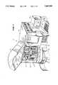
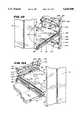
- FIG. 1is a perspective view of the front and right sides of a processing system that embodies the features of the invention, with some access panels and doors open to expose the interior portions to view;
- FIG. 2is a perspective view of the front and left sides of the system shown in FIG. 1, with other access panels and doors open to expose the interior portions to view;
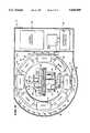
- FIG. 3is a top view of the interior of the system shown in FIG. 1, with some portions shown diagrammatically;
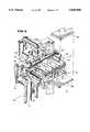
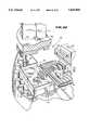
- FIG. 4is a perspective view of the interior regions of the system, showing the tray holding stations, the detecting station, and associated carrier mechanism, with portions broken away;
- FIG. 5is an enlarged perspective view of the right side of the interior regions of the system shown in FIG. 4;
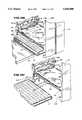
- FIG. 6is an enlarged perspective view of the carrier mechanism associated with the system, taken from left side, showing the movable platform that holds the specimen tray in its outward extended position;
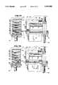
- FIGS. 7A and 7Bare side sectional views, taken generally along line 7--7 in FIG. 3, showing the movable platform picking up a specimen tray from a holding station;
- FIG. 8is a perspective view of the tray and associated cover that hold specimens during processing within the system
- FIG. 9is a perspective view of an operator loading a specimen tray (with cover) into the outward facing side of a holding station slot;
- FIG. 10is a perspective view of a specimen tray (with cover) stored within a holding station slot, as viewed from the outward facing side of the holding station;
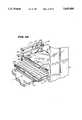
- FIGS. 11A, 11B, and 11Care perspective views of the movable platform operating within a holding station to remove a specimen tray, leaving the cover behind, as viewed from the inward facing side of the holding station;
- FIG. 12is a perspective view of the movable platform operating within a holding station to insert a specimen tray, leaving the cover behind, as viewed from the inward facing side of the holding station;
- FIG. 13is an enlarged perspective view of the photometric detecting station associated with the system shown in FIG. 1;
- FIG. 14is an enlarged side section view, taken generally along line 14--14 in FIG. 13, of the interior of two adjacent tray wells held upon the platform while in the photometric detecting station;
- FIG. 15is an enlarged perspective view, with portions broken away, of the light source associated with the photometric detecting station shown in FIG. 13;
- FIG. 15Ais a schematic showing the sequence of obtaining a processing reading at the photometric detecting station
- FIG. 15Bis a schematic flow chart showing the sequence of calibrating the position of the platform relative to the optical channels at the photometric detecting station
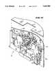
- FIG. 16is an enlarged perspective view of the fluorometric detecting station associated with the system shown in FIG. 1, with interior portions shown diagrammatically;
- FIG. 17is an enlarged perspective view, partially exploded, showing the rear portion of the reagent dispensing station carried within an access panel of the system shown in FIG. 1;
- FIG. 18is an enlarged exploded view of the reagent dispensing nozzle, its holder, and the associated docking fixture that embody the features of the invention
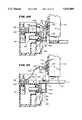
- FIG. 19is an enlarged side section view of the reagent dispensing nozzle, its holder, and the associated docking fixture shown in FIG. 18, with the docking fixture being moved into engagement with the nozzle;
- FIG. 20is an enlarged side section view of the reagent dispensing nozzle, its holder, and the associated docking fixture shown in FIG. 18, with the docking fixture engaged with the nozzle;
- FIG. 21is an enlarged side section view of the reagent dispensing nozzle, its holder, and the associated docking fixture shown in FIG. 18, with the docking fixture engaged with the nozzle and transporting the nozzle to the fluid dispensing area of the system shown in FIG. 1;
- FIG. 22is a perspective view showing the manipulation of the reagent dispensing while releasably attached to the docking fixture at the fluid dispensing area of the system;
- FIG. 23is a schematic view of a stepper motor control circuit associated with the system shown in FIG. 1.
- FIGS. 1 to 3show the general arrangement of an analytical system 10 that incorporates the features of the invention.
- the analytical system 10can be used in different environments to carry out different types of analytical, laboratory, and clinical procedures.
- the inventioncan be used in association with systems that require accurate and reproducible transfers of fluid in Clinical, medical, and industrial environments.
- the inventionalso can be used in association with systems that do assays for targeted materials or that analyze and identify biologic specimens.
- This Specificationdescribes a preferred embodiment of the invention operating as part of a device for screening liquid samples to identify microorganisms and test for their susceptibility to certain antibiotics.
- the system 10handles trays 12 carrying previously prepared suspensions of microbiologic specimens.
- the system 10incubates the specimens within the trays 12, adds reagents to them, and analyzes them according to a prescribed protocol.
- the system 10carries out these processes by sequentially transporting the specimen trays to various work stations 14, 16, 18 under the control of an onboard central microprocessor 20 (see FIG. 3).
- the central processor 20is preprogrammed to follow at least one prescribed analytical protocol.
- the system 10includes stations 14 that hold the specimen trays 12 for incubation; a station 16 that dispenses reagents into the specimen trays; and a station 18 that detects and quantifies the growth of microorganisms in the specimen trays.
- the detection station 18measures microbic growth by either photometric or fluorometric techniques.
- a cabinet 22encloses the stations 14, 16, and 18 and the central processor 20.
- a carrier 24transports the trays 12 among the stations 14, 16, and 18 within the cabinet 22 under the control of the central processor 20.
- the operatorsends and receives system status and control information from the central processor 20 through an onboard input/output panel 26.
- a nearby input/output CRT-keyboard console 28is also linked by cable to the central processor 20 (as FIG. 1 shows).
- the system 10also includes an onboard environment controller 30 operated by the central processor 20.
- the controller 30maintains a circulating air flow pattern 32 (shown by arrows in FIG. 3) through ducting within the principal processing region 34 of cabinet 22, where the holding stations 14 are located.
- the air flow pattern 32is heated and humidified to establish conditions necessary to incubate the specimens carried in the holding stations 14.
- the air flow pattern 32typically maintains a temperature of about 37 degrees C within the main incubation region 34.
- the cabinet 22includes doors 36 and 38 that permit periodic access into the enclosed interior regions of the cabinet 22.
- the door 36opens into the main incubation region 34 (see FIG. 2). When open, the door 36 allows the operator to load or remove specimen trays from a holding station 14. To preserve the incubating conditions within the region 34, the central processor 20 normally locks the door 36 to prevent unrestricted access. The central processor 20 opens the door 36 only in response to a proper access request code, which the operator enters using the console 28.
- the door 38opens into the lower region 40 of the cabinet 22, where the reagent dispensing station 16. When open, the door 38 allows the operator access to the interior of the reagent dispensing station 16 to load or remove reagent source containers 42. Since the interior of the reagent dispensing station 16 is largely isolated from the main incubation region 34, the operator can open the door 38 without first entering an access request code to the central processor 20.
- the service panel 44opens into the main incubation region 34.
- the service panel 46opens into the lower region 40 and carries the entire reagent dispensing station 16.
- the holding stations 14are vertically stacked into towers within the main incubation region 34.
- the number of holding stations 14can vary, as can the number of trays 12 each holding station 14 carries. In the illustrated embodiment, there are eight holding stations 14, each containing six slots 50 to hold individual specimen trays 12 (see FIG. 9 also).
- a carousel 52moves the stacked holding stations 14 in a circular track around the carrier 24.
- a first stepper motor 54powers an associated belt drive 56 under the control of the central processor 20 to index the carousel 52. In this way, each holding station 14 can be brought to an access position, which holding station 14' occupies in FIG. 3. In this position, one side 58 of the holding station 14' faces inward toward the carrier 24, while the other side 60 faces outward toward the access door 36.
- a pair of tie-down bolts 62attach each holding station 14 to the carousel 52. By unfastening the tie-down bolts 62, the operator can remove individual holding stations 14 for maintenance, cleaning, or sterilization.
- Each tray 12 stacked within the holding station 14includes an array of specimen wells or cuvettes 48 (as FIG. 8 best shows) arranged in aligned rows and columns.
- each tray 14includes ninety-six wells 48 arranged in eight rows of twelve wells 48 each.
- the trays 12are intended to be a single-use, disposable component of the system 10. So, the trays 12 are typically made of an inert plastic material.
- the plastic materialcan be light transmissive to permit analysis of the specimens by photometry. Alternatively, the plastic material can be opaque to permit analysis of the specimens by fluorometry.
- the tray wells 48contain various reaction agents. When incubated, the specimens react with these agents within the wells 48 to create differing distinctive patterns of color or turbidity changes, or fluorescence in the tray 12. Sometimes, a reagent must be added to trigger the needed reaction for analysis. By creating and then analyzing these patterns, the system 10 detects the presence of a given type of microorganism and its degree of susceptibility to various microbiotic agents.
- the operatorprepares a culture medium containing a suspension of the microorganism to be analyzed.
- the operatorintroduces this suspension into the wells 48 of a specimen tray 12.
- the operatordoes this task at a specimen preparation station (not shown) outside the system cabinet 22.
- the operatorplaces a cover 86 on the tray 12 to minimize fluid loss by evaporation (see FIG. 8).
- the coverincludes a pair of projecting tabs 88 that extend horizontally beyond two sides of underlying tray 12.
- the processor 20maintains an inventory of trays 12 within the holding stations 14 (as will be described later), and, with it, the processor 20 locates the position of empty holding slots 50.
- the central processor 20provides the operator with a listing of empty holding slots 50. The operator uses this listing to designate a holding station 14 via the data input panel 26 or console 28.
- the central processor 20indexes the carousel 52 to place the user-designated holding station 14 in the access position (where FIGS. 3 and 7A/B show holding station 14' to be). The processor 20 then unlocks the door 36.
- the operatormanually loads the medium-filled specimen tray 12 with its cover 86 into an open holding slot 50 through the outward facing side 60 of the station 14 (as FIG. 9 best shows).
- each slot 50is open except for opposite pairs of vertically spaced top and bottom support ledges 210 and 212.
- the bottom ledges 212extend farther into the slot 50 than the top ledges 210.
- the bottom ledges 212end with upturned edges 214 at both inward and outward facing sides 58 and 60 of the slot 50.
- FIG. 9shows, the operator inserts the tray 12 and cover 86 through a slotted opening 216 in the outward facing side 60 into the slot 50.
- FIG. 10shows, the bottom of the tray 12 comes to rest upon the bottom ledges 212.
- the upturned edges 214prevent horizontal movement of the tray 12 within the slot 50.
- the projecting tabs 88 on the overlying cover 86extend above the plane of the top support ledges 210, making no contact with them.
- Springs 218press against the projecting tabs 88 to hold the cover 86 on the underlying tray 12.
- the central processor 20After loading the tray 12, the operator closes the door 36. From this point onward, the central processor 20 automatically conducts the analysis of the tray 12 without further involving the operator.
- the central processor 20sequentially actuates the carrier 24 to shuttle each tray 12 to and from the holding station 14, stopping either at the detection station 18 or the reagent dispensing station 16.
- the carrier 24transports a given tray 12 several times between the holding station 14 and detection station 18 for successive analysis, with at least one intermediate stop at the reagent dispensing station 16.
- the detection station 18quantifies the microbic growth observed on each specimen tray 12.
- the central processor 20is linked to an external printer station (not shown). There, the processor 20 periodically generates written reports for the operator that contain a complete analysis for each specimen tray 12.
- FIGS. 5 and 6show the details of the carrier 24.
- the carrier 24includes a frame 64 supported on a pair of vertical shafts 66.
- a second stepper motor 68powers an associated belt drive 70 to rotate a vertical axis lead screw 72 under the control of the central processor 20.
- the rotating vertical lead screw 72moves the carrier frame 64 in a stepwise fashion up and down along the shafts 66. This mode of operation brings the carrier frame 64 into vertical alignment with any selected slot 50 of a holding station 14 occupying the access position.
- the carrier 24also includes a horizontal platform 74 mounted on a pair of tracks 76 on the frame 64.
- a third stepper motor 78powers an associated belt drive 80 (see FIG. 6) to rotate a horizontal axis lead screw 82 under the control of the central processor 20.
- Rotation of the lead screw 82advances the platform 74 in stepwise fashion along a horizontal path between a fully retracted position within the carrier frame 64 (see FIGS. 5 and 7B) and a fully extended position outside the carrier frame 64 (see FIGS. 6 and 7A).
- FIG. 7Ashows, when moved toward its fully extended position, the horizontal platform 74 enters an aligned holding slot 50 beneath the occupying tray 12 through the inward facing side 58 of the station 14. Slight rotation of the vertical lead screw 72 lifts the platform 74. The open bottom of each slot 50 permits upward movement of the platform 74 into engagement with the underside of the tray 12.
- the platform 74includes an array of pockets 84.
- the convex undersides 0f the tray wells 48nest within the pockets 84 so that the tray 12 cannot slide horizontally on the platform 74.
- the pocket bottoms 85are open and do not interfere with the intended transmission of light through the tray wells 48.
- FIGS. 11Ashows, further operation of the lead screw 72 lifts the platform 74 and, with it, the covered tray 12 within the slot 50.
- the lifting movement(coupled with slight movement of the platform 74 inward, as shown by arrows in FIG. 11A) slips the inward facing edges of the projecting cover tabs 88 into upper detents 220, which are located within the slot 50 above the top support ledges 210.
- FIG. 11Bshows, slight opposite rotation of the lead screw 72 lowers the tray 12, leaving the edges of the cover 86 engaged within the upper detents 220.
- FIG. 11Cshows, rotation of the horizontal lead screw 82 moves the platform 74 out of the holding slot 50.
- the platform 74carries the engaged tray 12, but leaves the cover 86 behind (as FIG. 7B also shows).
- the portion 222 of the top support ledge 210 that extends toward the outward facing side 60 of the slot 50slopes downward toward the bottom support ledge 212.
- the springs 218press against the cover 86 at the junction of the sloped portion 222 with the rest of the top support ledge 210.
- FIG. 11Cshows, as the platform 74 withdraws the tray 12, the springs 218 pivot one end of the cover 86 down against the sloped portion 222, while the opposite end of the cover 86 remains engaged within the upper detents 220.
- the cover 86assumes this tilted position within the slot 50 (as FIG. 7B also shows) as the platform 64 withdraws the tray 12.
- the cover 86remains in this tilted position as the platform 64 transports the associated coverless tray 12 outside the holding slot 50.
- FIG. 12shows, when the platform 74 returns the tray 12 to the slot 50, the entering edge of the tray 12 contacts the tilted portion the cover 86.
- the horizontal movement of the tray 12pulls the cover 86 free of the detents 220, as FIG. 12 shows.
- the horizontal movementalso pivots the cover 86 about the spring back into its original horizontal position on top of the tray 12. Slight rotation of the vertical lead screw 72 lowers the platform 64 from engagement with the now covered tray 12. Rotation of the horizontal lead screw 82 returns the platform 74 to its retracted position within the frame 64.
- the central processor 20maintains an inventory of the trays 12 undergoing processing within the system 10. As FIG. 8 shows, each tray 12 carries a unique identification label 206 written in bar code or another machine readable format.
- the carrier 24includes a scanning device 208 (see FIG. 4) for reading the tray labels 206.
- the central processor 20indexes the carousel 52 to bring the holding station 14 to a scanning position in alignment with the device 208 (which is essentially 180 degrees from the access position previously described).
- the central processor 20operates the vertical lead screw 72 to advance the scanning device 208 to view the label 206 of each tray 12 in the holding station 14, while operating the carousel 52 to advance the label 206 horizontally past the device 208 to scan in the bar code information it contains.
- the central processor 20creates and updates an inventory record of trays 12 each time an operator loads a tray 12 into the system 10.
- the central processor 20further updates the inventory record for each tray 12 to note the time and nature of the processing steps conducted.
- the inventory recordestablishes the holding station slot for the tray 12, the time the tray entered the system, the time and nature of each processing step involving the tray 12, and the results of the analyzes conducted on the tray 12.
- the central processor 20relies upon the preprogrammed protocol and real time inventory record it creates to control the processing sequence for each tray 12 within the system 10.
- the central processor 20coordinates the rotation of the vertical lead screw 72 with the carousel belt drive 56 to orient the carrier 24 with a selected slot 50 of a holding station 14. Then, by operating the horizontal lead screw 82, the central processor 20 operates the platform 74 to remove the specimen tray 12 and later return the specimen tray 12 to the aligned holding slot 50.
- the carrier 24transports the engaged specimen tray 12 outside the holding slot 50 to either the detection station 18 or the reagent dispensing station 16, depending upon the commands of the central processor 20.
- the carrier frame 64supports the detection station 18. Still, it should be appreciated that the detection station 18 could be located away from the carrier frame 64 at another location within the cabinet 22.
- FIG. 13shows the details of the detection station 18.
- the detection station 18includes both a photometric reader 96 and a fluorometric reader 98.
- the photometric reader 96optically detects the presence of either color change or turbidity in a given specimen and by that derives a measure of microbiotic activity.
- the fluorometric reader 98detects fluorescence within a given specimen to measure microbiotic activity. Whether a given specimen undergoes analysis by the photometric reader 96 or the fluorometric reader 98 depends upon the particular protocol of the analytical procedure that the central processor 20 follows.
- the photometric reader 96includes a light source assembly 100 comprising twelve fiber optic emitter lines 102 that lead from a single light source 104 (the details of which are shown in FIG. 15).
- the optic emitter lines 102are arranged in a horizontal, spaced apart relationship on the frame 64 below the path of movement of the platform 74. The distance between adjacent optic emitter lines 102 corresponds with the distance between adjacent wells 48 within each row on the specimen tray 12.
- the optic emitter lines 102transmit light upward through the specimen tray 12 on the platform 74, individually illuminating one entire row (i.e., twelve wells 48) at a time.
- Each optic emitter line 102includes a lens (not shown) that condenses the light beam exiting the optic fiber into a narrow vertical beam, by that maximizing the illumination of each well 48.
- the light source 104is separated from the input end of each fiber optic line 102 by a color wheel 108.
- the wheel 108includes six light filters 110 and one opaque disk 111 spaced about its periphery. Each filter 110 limits the light entering the fiber optic lines 102 to a discrete, pre-determined wavelength.
- the opaque disk 111blocks all transmission of light to the emitter line 102 when, for example, when the fluorometric reader 98 is in operation or during calibration, as set forth in more detail later.
- a fourth stepper motor 112rotates the color wheel 108 to position the desired filter 110 or disk 111 in the light path under the control of the central processor 20.
- the photometric reader 96also includes twelve photodiode detectors 106 paired with the twelve optic emitter lines 102.
- the twelve photodiode detectors 106face the optic emitter lines 102 on the frame 64 above the path of movement of the platform 74.
- the photodiode detectors 106sense light after its transmission through the specimens in the wells 48.
- the central processor 20indexes the tray-carrying platform 74 stepwise between the twelve paired emitters and detectors 102/106.
- the photometric reader 96includes a programmable gain amplifier 113 (see FIG. 15A) that is capable of providing fixed levels of amplification, called gain stages.
- a digital processor 114analyzes the sensed signal at a preselected selected gain stage to determine either the color or turbidity of the specimens.
- multiple photometric readingsare typically taken of the specimens at predetermined intervals during the incubation period.
- Each emitter/detector pair 102/106constitutes one independent optical channel C1 to C12 that, in use, transits one tray well 48.
- the central processor 20independently calibrates each optical channel C1 to C12 to obtain a reading representative of the absorption of the sample within the associated tray well 48.
- Independent calibrationallows the differences between the twelve individual channels C1 to C12 to be cancelled out.
- Independent calibrationaccommodates greater mechanical and electrical tolerances among the channels C1 to C12 than the calibration of all channels to a common reference point. Independent calibration cancels out these differences among the channels without, adversely affecting the overall accuracy of the photometric reader 96.
- the calibration procedure for each optical channel C1 to C12is the same.
- the procedurebegins with the platform 74 carrying no tray 12.
- the central processor 20places the opaque disk 111 in the light path to block transmission of light to all optical channels.
- a separate readingis taken for each channel at each gain stage of the amplifier 113. These readings represents the dark signals (electrical off-set) for each gain stage of each channel.
- the central processor 20retains these readings for each optical channel in memory.
- the central processor 20then sequentially brings a filter 110 into the light path. While no tray 12 occupies the platform 74, a reading is taken.
- the central processor 20selects the gain stage of the amplifier 113 that achieves an on-scale reading. This becomes the preselected gain stage for that channel for that particular filter 110 (wavelength).
- the on-scale reading at that gain stagebecomes the reference for that channel for that particular filter 110 (wavelength). Because each channel is calibrated independent of the other channels, each optical channel may and probably will have a different gain stage and reference for each filter 110.
- the calibration procedurerepeats this sequence for each filter (wavelength) 110, obtaining an associated gain stage and reference for each channel.
- the central processorretains these values in memory.
- the central processor 20thus maintains for each filter (wavelength) 110 three calibration values for each optical channel C1 to C12. These calibration values represent the gain stage (G) selected to obtain an on-scale reading for the filter 110; the reference reading taken at the selected gain stage (R G ); and the dark reading earlier obtained for the selected gain stage (D G ).
- FIG. 15Ashows with respect to each optical channel (designated C n in FIG. 15A), a subsequent reading in that optical channel at a particular filter wavelength (R RAW ) is taken at the selected gain stage (G) for that filter 110.
- the central processoralters the subsequent reading (R RAW ) to obtain a processing reading (R PROC ) for each optical channel, as follows: ##EQU1##
- the processing reading R PROCis representative of the absorbance of the sample taken at that optical channel. Due to the calibration process, the processing reading R PROC for each optical channel is hardware independent.
- the central processor 20also calibrates the position of the platform 74 relative to the optical channels to properly locate the openings 85 in the platform 74 within the light paths.
- FIG. 15Bshows the sequence of the platform calibration procedure.
- the platform 74is drawn through the light paths. For each optical channel, the amount of light reaching the associated detector 106 increases as the outer edge of the associated opening 85 enters the light path. The light signal reaches a maximum value when the center of the opening 85 occupies the light path. The light signal then decreases as the inner edge of the opening 85 enters the light path to block the light.
- the central processor 20marks the position of the platform 74 (based upon the particular step of the stepper motor 78) when a preselected threshold value is reached at the inner and outer edges of the associated opening 85.
- the center of the opening 85is determined for that particular optical channel by averaging these two marked positions.
- the determined centers for the optical channelare themselves averaged to derive an average center position for the stepper motor 78 for each row of openings 85.
- the central processor 20indexes the platform 74 to best position the centers of the openings 85 along each row into the optical channels.
- the openings 85are fixed on the platform 74, and the tray is preformed so that the centers of its wells 48 nest within the platform 74 in registration with the centers of the openings 85.
- the calibration procedure just described and as set forth in FIG. 15Bneed be performed for each system 10 only upon initial setup and after repair and/or replacement of the platform 74 or its associated drive assemblies.
- FIG. 16shows the details of the fluorometric reader 98.
- the fluorometric reader 98includes a movable head 116 that travels along a horizontal track 118 on the carrier frame 64 above the path movement of the platform 74.
- the track 118extends transversely across the path of platform movement.
- a fifth stepper motor 120powers an associated belt drive 122 that moves the head 116 back and forth along the track 118.
- the head 116encloses a fluorometer, the interior details of which are shown in FIG. 16.
- the fluorometerincludes a source lamp 124 that directs light to an excitation filter 126 through a quartz light path 128.
- An output lens 130directs the out coming light onto the specimen contained in an underlying well 48.
- the specimencontains a material that, in the presence of a target microorganism, reacts to the light energy by fluorescing.
- the resulting fluorescenceis directed by an input lens 132 to an emission filter 134 for the expected wavelength.
- a photomultiplier tube 136 and a preamplifier 138translate the light signal to an analog output that is directly proportional to the amount of fluorescence detected.
- An analog-to-digital converter 140(which is carried on the frame 64 and is attached to the movable head 116 by a cable 142) converts the analog output of the photomultiplier tube 136 to digital output.
- the converter 140also includes the power supply for components carried within the movable head 116.
- the carrier platform 74indexes a row of wells 48 into position below the head 116.
- the central processor 20moves the head 116 down the wells 48, obtaining the fluoresced light signal for each well 48 and transmitting it to the processor 140.
- FIGS. 17 to 22show the details of the reagent dispensing station 16.
- the reagent dispensing station 16occupies the region 40 below the carousel 52 at the front of the cabinet 22 (see FIGS. 1 and 2). It is housed within the service panel 46 essentially out of the main incubation region 34 area of the system 10.
- the panel 46contains a reagent dispensing area 144, a pressurized reagent source 146, and a reagent dispensing nozzle 148.
- the source 146contains different reagent types contained in individual containers or vials 42 (see FIGS. 1 and 15).
- Tubing manifold 150connects each vial 42 to a positive pressure pump 152.
- Each reagent vial 42also includes an outlet tube 154 with an inline solenoid valve 156 that is under the control of the central processor 20. When closed, the solenoid valve 156 blocks the flow of reagent from the pressurized vial 42. When opened, the solenoid valve 156 permits reagent to flow under positive pressure from the vial 42 through the associated outlet tubing 154.
- the outlet tubing 154 for the reagent vials 42all leads to the dispensing nozzle 148.
- the dispensing nozzle 148includes individual fluid dispensing ports 158 (see FIG. 18), one for each type of reagent.
- the solenoid valve 156opens for a particular source reagent vial 42
- the particular reagent in the vial 42flows under positive pressure out the associated dispensing port 158 in the nozzle 148.
- the dispensing ports 158are symmetrically arranged at predetermined intervals relative to the centerline of the nozzle 148 to allow precise positioning over the intended well 48 by the stepper motors controlled by the central processor 20 (as will be described in greater detail later).
- a holder 160When not in use, a holder 160 retains the nozzle 148 on the dispensing station 16 away from the fluid dispensing area 144. In the illustrated embodiment, the holder 160 is located a short distance below the dispensing area 144 and close to the reagent source 146.
- a movable latch 162(see FIG. 18) within the holder 160 is biased by springs 164 into engagement with a tab 166 on the nozzle 148. This engagement locks the nozzle 148 in place inside the holder 160 (as FIG. 19 shows).
- Tubing 176periodically brings washing fluid from a source container 182 into the holder 160 using the positive pressure pump 184.
- the periodic pressurized spray of fluidwashes the interior of the holder 160. It can also be used to wash the nozzle 148 resting within the holder 160.
- the washing fluiddrains through an exit tube 178 into a disposable collection bag 180.
- Tubing 177periodically brings pressurized air into the holder 160 to air dry the nozzle 148 after washing.
- the compact arrangement of all components of the reagent dispensing station 16 out of the main incubation region 34allows the reagent source 146 to be positioned close to the dispensing nozzle 148.
- the lengths of outlet tubing 154 supplying reagent to the nozzle 148can be significantly shortened.
- the tubing 154need be long enough only to allow the nozzle 148 to reach the holder 160 and the reagent dispensing area 144.
- the tubing 154need not be long enough to allow the nozzle to reach beyond the reagent dispensing station 16 and into the main incubation region 34 of the system 10. Because of the short length of the tubing 154, the amount of positive pressure required to convey the reagent in the system 10 can be considerably reduced.
- the reagent dispensing stationuses only about 25% as much tubing. It also operates at a fluid pressure of only 3 PSI (pounds per square inch) instead of the 8 PSI that conventional systems must use. The reduction of positive pressure within the system considerably reduces the formation of air blocks caused by fluid outgassing within the tubing 154.
- a solenoid 168selectively energized by the central processor 20 moves the latch 162 away from the nozzle tab 166 against the force of the biasing spring 164 (as FIG. 20 shows). This frees the nozzle 148 for removal from the holder 160 when it is time to dispense reagent.
- the carrier 24includes a docking fixture 170 for engaging the nozzle 148 to transport it between the holder 160 and the reagent dispensing area 144. While at the dispensing area 144, the central processor 20 coordinates the movement of the platform 74 and the docking fixture 170 with operation of the reagent dispensing source 146 to introduce reagent into one or more specimen-containing wells.
- the docking fixture 170releases the nozzle 148 after dispensement of reagent. More particularly, the carrier 24 returns the nozzle 148 to the holder 160 and there releases the docking fixture 170. This mode of operation frees the carrier 24 for other transport functions within the system 10, while the nozzle 148 lays at rest within its holder 160.
- the docking fixture 170is attached to the movable head 116 of the fluorescence reader 98. Operation of the fifth stepper motor 120 moves the docking fixture 170 along the horizontal track 118 above the tray platform 74.
- the illustrated embodimentemploys magnetism to releasably engage the docking fixture 170 to the nozzle 148.
- the docking fixture 170carries a permanent rare earth magnet 174.
- the nozzle 148includes a surface 172 that nests within the fixture 170.
- the mating surface 172includes material that is attracted by the magnet 174 the fixture 170 carries.
- the mating surface 172could carry another rare earth magnet.
- the central processor 20coordinates the operation of the first, second, and third stepper motors 54, 68, and 78 to engage a selected specimen tray 12 on the platform 74 within the main incubation region 34 of the system 10.
- the central processor 20moves the platform 74 into its fully retracted position within the carrier frame 64.
- the central processor 20then moves the carrier 24 vertically downward into the reagent dispensing region 40 (as FIG. 19 shows).
- the nozzle 148rests in a locked condition within the holder 160 (i.e., the latch solenoid 168 is not energized).
- the docking fixture 170moves downward and nests with the nozzle surface 172 (as FIG. 20 shows).
- the nesting fixture 170magnetically engages the nozzle surface 172.
- the central processor 20energizes the solenoid 168 to withdraw the latch 162, freeing the nozzle 148 within the holder 160.
- the central processor 20moves the carrier 24 vertically upward.
- the fixture 170lifts the magnetically engaged nozzle 148 from the holder 160 and into the reagent dispensing area 144 (as FIGS. 21 shows).
- the central processor 20then operates the third stepper motor 78 to move the tray-carrying platform 74 out of the carrier frame 64 into the fluid dispensing area 144.
- the central processor 20horizontally positions a row of the specimen tray 12 beneath the nozzle 148 while it transversely positions the nozzle 148 along this row to bring the desired specimen well 48 under the desired reagent dispensing port 158.
- the central processor 20then opens the solenoid valve 156 associated with the vial 42 for the desired reagent to dispense a predetermined aliquot of the desired reagent into the selected well 48.
- the central processor 20positions the nozzle 148 engaged by the movable fixture 170 by dead reckoning.
- the processor 20measures the position of the fixture 170 along the track 118 in steps sent to the fifth stepper motor 120 from the fixture's home position.
- the drive system of the stepper motor 120is calibrated using the fluorometer located within the transport head 116, which also carries the fixture 170.
- the system start-up routineincludes an initialization process that uses an onboard encoder bar 224 and an optical interrupter 226. As FIGS. 5 and 6 best show, the optical interrupter 226 is carried on the movable head 116 of the fluorescence reader 98 behind the belt drive 122.
- the encoder bar 224is also carried on the platform 74 behind the belt drive 122.
- the encoder bar 224includes a series of spaced apart teeth 228 sandwiched between the optical interrupter 226 along its path of movement.
- the centerlines of the teeth 228mark the centerline positions of the tray wells 48 when the tray 12 is present on the platform 64.
- the optical interrupter 226scans the encoder bar 224.
- the teeth 228block light transmission through optical interrupter 226.
- the spacing between the teeth 228allows light transmission through the optical interrupter 224.
- the interrupter 224senses sequential conditions of light and no light.
- the central processor 20uses this table to guide the centerline of the nozzle 148 to a particular well 48 during reagent dispensing operations. Additional incremental stepping actions of the motor 78 and the motor 120 under the control of the central processor 20 align the selected nozzle port 158 over the selected well 48.
- the central processor 20moves the tray-carrying platform 74 into its fully retracted position.
- the central processor 20vertically lowers the carrier 24 to return the nozzle 148 to its holder 160.
- the solenoid 168is not energized, and the spring-biased latch 162 snaps into locking engagement with the nozzle tab 166.
- the central processor 20moves the carrier 24 vertically upward.
- the magnet attraction holding the nozzle surface 172 to the fixture 170is such that vertical movement of the carrier 24 while the nozzle 148 is locked within the holder 160 overcomes the force of the magnetic coupling, separating the nozzle surface 172 from the docking fixture 170.
- the carrier 24is thereby freed to return the engaged specimen tray 12 (now with added reagent) back to the main incubation region 34 for further processing.
- the central processor 20includes a motor driver system 186 (see FIG. 23) for controlling the stepper motors 54; 68; 78; 112; and 120 associated with the system 10.
- the system 186includes a conventional field effect transistor (FET) 188 connected in series with the motor coil 190.
- FETfield effect transistor
- a phase controller 191controls voltage to the FET 188, by that controlling its phase of operation. In an on phase, the controller 191 supplies voltage to the FET 188. This allows current to flow through the coil 190. In an off phase, the controller 191 supplies no voltage to the FET 188. This interrupts current flow through the coil 190.
- the associated stepper motorincludes a rotor and two or more coils 190 under the control of the controller 190.
- the controller 191successively supplies current to the coils 190 to step the motor rotor to its successive operating positions.
- a FET controller 193provides either a true or not true enable signal that switches the FET 188 for the coil 190 between an on state (when true) and an off state (when not true).
- the chop controller 201When current is applied to the coil 190 (i.e., during its on phase of operation), the chop controller 201 rapidly switches the FET 188 between its on and off states, modulating the current and keeping it from rising above the nominal motor current (for example, 5 amps). The current rises and falls as the FET 188 switches on and off, creating a conventional unipolar chopping mode drive effect. In the chopping mode, the FET 188 keeps the average current in the coil 190 from rising above the nominal, relatively low motor current, despite a relatively high applied voltage (for example, 40 volts).
- the system 186also includes a flyback circuit 192 for each motor coil 190.
- the flyback circuit 192includes a conventional steering diode 194 and a conventional zener-diode 196.
- the zener-diode 196is connected in the reverse bias direction. The zener-diode 196 thus normally resists flow of current in the direction through the steering diode 194, until its breakdown voltage is reached.
- the flyback circuit 192also includes a conventional snubber circuit, consisting of series resistor 198 and capacitor 200.
- the flyback circuit 192further includes two conventional bipolar transistors 202 and 204.
- the first transistor 202is a PNP-type whose base is connected to the coil controller 191.
- the first transistor 202acts as a switch under the control of the coil controller 191.
- the first transistor 202conducts current (a switched closed state) when current is supplied to the coil 190 (during its on phase of operation).
- the first transistor 202does not conduct current (a switched opened state) when no current is supplied to the coil 190 (during its off phase of operation).
- the second transistor 204is an NPN-type. Its base to emitter voltage is selectively biased to two different voltages, one high and the other low, depending upon a phase of operation of the coil 190. The bias voltage, in turn, affects the overall dissipation of power through the flyback circuit 192.
- the collector of the second transistor 204is connected to the steering diode 194 to conduct current from the coil 190.
- the emitter of the second transistor 204is connected to the coil 190 to return this current to the coil 204, minus any energy dissipated by the transistor 204.
- the base of the second transistor 204is connected to the collector of the first transistor 202.
- the collector of the second transistor 204is connected to the emitter of the first transistor 202 between the steering diode 194 and the zener-diode 196.
- the zener-diode 196is connected in the reverse biased direction (during the off phase of the controller 191) between the collector and base of the second transistor 204.
- the coil 190Will dissipate retained stored energy into the flyback circuit 192 whenever the FET 188 interrupts current flow through the coil 190 (i.e., when the FET 188 is switched off while the controller 191 operates the coil 190 in its on phase mode).
- the coil 190also will dissipate retained stored energy into the flyback circuit 192 whenever current to the coil 190 itself terminates (i.e., when the controller 191 switches operation from the on phase mode to the off phase mode).
- the FET 188repeatedly interrupts current flow through the coil 191 at short intervals while the motor coil 190 operates in its chopping mode. Whenever the FET 188 switches off (when the controller 193 provides a "not true” enable signal) energy discharged by the coil 190 enters the flyback circuit 192.
- the coil 190is in its on phase.
- the coil controller 191biases the base of the first transistor 202 to a switched closed state.
- the first transistor 202conducts current at a first voltage, which is less than the breakdown voltage of the zener-diode 196.
- the current in the flyback circuit 192flows through the steering diode 194 and through the path of least electrical resistance, which is through the first transistor 202.
- the zener-diode 196operates below its breakdown voltage in its reverse direction to block current flow in its path.
- the currentflows through the first transistor 202 to the base of the second transistor 204.
- the first transistor 202biases the base emitter junction of the second transistor 204 at the first, relatively low voltage.
- the first voltageis generally about 2 volts.
- the flyback circuit 192recirculates current through the second transistor 204 with little dissipation during the intervals while the FET 188 is switched off. This sustains a smooth, constant torque while the coil 190 is energized (i.e., receiving voltage) and operating in its chopping mode. Due to the low voltage mode of the flyback circuit 192, the stepper motor provides steady, sustained power.
- the controller 191switches the coil 190 to its off phase
- the coil 190again discharges its energy into the flyback circuit 192 (the enable signal transmitted to the FET 188 has no effect once the controller 191 operates in its off phase). Since the coil 190 is now in its off phase, the first transistor 202 is in its switched open state and does not conduct current.
- the currentflows through the steering diode 194 directly into the path of the zener-diode 196.
- the reverse currentis such that the zener-diode 196 quickly reaches its breakdown voltage.
- the zener-diode 196then conducts current to bias the second transistor 204 at a second voltage, which is the breakdown voltage of the zener-diode 196.
- the second voltageis generally about 180 volts.
- the flyback powerquickly dissipates the energy stored in the coil 190. This rapid dissipation of energy provides a smooth and quick transition of voltage to the successor coil.
- the high voltage mode of the flyback circuit 192provides sustained speed to the stepper motor.
- system 10in the illustrated embodiments is not intended to limit the scope of the invention to the particular types of analytical systems or particular type of analytical techniques disclosed in this specification.
- system 10 that embodies the inventioncan be used to conduct different analyzes, besides the microbiotic susceptibility procedures described. It will be seen and appreciated that the invention is applicable for use with diverse analytical types and techniques, though they are not all described in detail in this application.
Landscapes
- Physics & Mathematics (AREA)
- Health & Medical Sciences (AREA)
- Life Sciences & Earth Sciences (AREA)
- Chemical & Material Sciences (AREA)
- Analytical Chemistry (AREA)
- Biochemistry (AREA)
- General Health & Medical Sciences (AREA)
- General Physics & Mathematics (AREA)
- Immunology (AREA)
- Pathology (AREA)
- Automatic Analysis And Handling Materials Therefor (AREA)
- Investigating Or Analysing Materials By Optical Means (AREA)
Abstract
Description
Claims (6)
Priority Applications (1)
| Application Number | Priority Date | Filing Date | Title |
|---|---|---|---|
| US08/458,315US5645800A (en) | 1991-10-31 | 1995-06-02 | Specimen processing and analyzing systems with associated fluid dispensing apparatus |
Applications Claiming Priority (3)
| Application Number | Priority Date | Filing Date | Title |
|---|---|---|---|
| US78618491A | 1991-10-31 | 1991-10-31 | |
| US08/270,728US5518686A (en) | 1991-10-31 | 1994-07-05 | Specimen processing and analyzing systems with associated fluid dispensing apparatus |
| US08/458,315US5645800A (en) | 1991-10-31 | 1995-06-02 | Specimen processing and analyzing systems with associated fluid dispensing apparatus |
Related Parent Applications (1)
| Application Number | Title | Priority Date | Filing Date |
|---|---|---|---|
| US08/270,728DivisionUS5518686A (en) | 1991-10-31 | 1994-07-05 | Specimen processing and analyzing systems with associated fluid dispensing apparatus |
Publications (1)
| Publication Number | Publication Date |
|---|---|
| US5645800Atrue US5645800A (en) | 1997-07-08 |
Family
ID=25137835
Family Applications (2)
| Application Number | Title | Priority Date | Filing Date |
|---|---|---|---|
| US08/270,728Expired - LifetimeUS5518686A (en) | 1991-10-31 | 1994-07-05 | Specimen processing and analyzing systems with associated fluid dispensing apparatus |
| US08/458,315Expired - LifetimeUS5645800A (en) | 1991-10-31 | 1995-06-02 | Specimen processing and analyzing systems with associated fluid dispensing apparatus |
Family Applications Before (1)
| Application Number | Title | Priority Date | Filing Date |
|---|---|---|---|
| US08/270,728Expired - LifetimeUS5518686A (en) | 1991-10-31 | 1994-07-05 | Specimen processing and analyzing systems with associated fluid dispensing apparatus |
Country Status (6)
| Country | Link |
|---|---|
| US (2) | US5518686A (en) |
| EP (1) | EP0565699A1 (en) |
| JP (1) | JPH06504136A (en) |
| AU (1) | AU656826B2 (en) |
| CA (1) | CA2099282A1 (en) |
| WO (1) | WO1993009441A1 (en) |
Cited By (66)
| Publication number | Priority date | Publication date | Assignee | Title |
|---|---|---|---|---|
| US5817475A (en)* | 1996-11-15 | 1998-10-06 | Giles Scientific, Inc. | Automatic microbiological testing apparatus and method |
| WO1999015905A1 (en)* | 1997-09-24 | 1999-04-01 | Glaxo Group Limited | Systems and methods for handling and manipulating multi-well plates |
| US6024921A (en)* | 1996-02-21 | 2000-02-15 | Bio Merieux, Inc. | Incubation station for test sample cards |
| EP1058118A1 (en)* | 1999-06-04 | 2000-12-06 | Randox Laboratories Ltd. | Liquid dispenser on mobile support |
| WO2001004608A1 (en)* | 1999-07-07 | 2001-01-18 | Ljl Biosystems, Inc. | Light detection device |
| US6258326B1 (en) | 1997-09-20 | 2001-07-10 | Ljl Biosystems, Inc. | Sample holders with reference fiducials |
| US6297018B1 (en) | 1998-04-17 | 2001-10-02 | Ljl Biosystems, Inc. | Methods and apparatus for detecting nucleic acid polymorphisms |
| WO2000067037A3 (en)* | 1999-04-29 | 2001-10-11 | Dade Microscan Inc | A combined rapid anti-microbial susceptibility assay and microorganism identification system |
| US6317207B2 (en) | 1999-02-23 | 2001-11-13 | Ljl Biosystems, Inc. | Frequency-domain light detection device |
| US6326605B1 (en) | 1998-02-20 | 2001-12-04 | Ljl Biosystems, Inc. | Broad range light detection system |
| US20020006362A1 (en)* | 2000-07-13 | 2002-01-17 | Suzuki Motor Corporation | Sample assaying apparatus |
| US20020094581A1 (en)* | 1998-02-24 | 2002-07-18 | Michael Cole | Method and apparatus for determining temperature of and controlling the evaporation of liquid samples |
| US20020144879A1 (en)* | 2001-04-04 | 2002-10-10 | Anderson N. Leigh | Method and apparatus for relieving stress in an electrophoresis gel slab |
| US6466316B2 (en) | 1998-07-27 | 2002-10-15 | Ljl Biosystems, Inc. | Apparatus and methods for spectroscopic measurements |
| US6469311B1 (en) | 1997-07-16 | 2002-10-22 | Molecular Devices Corporation | Detection device for light transmitted from a sensed volume |
| WO2002084270A1 (en)* | 2001-04-04 | 2002-10-24 | Large Scale Proteomics Corporation | Automated electrophoresis gel manipulation apparatus and method |
| WO2002090966A1 (en)* | 2001-05-10 | 2002-11-14 | Large Scale Proteomics Corporation | Automated apparatus for separating a biological sample from a two dimensional electrophoresis gel |
| US6483582B2 (en) | 1998-07-27 | 2002-11-19 | Ljl Biosystems, Inc. | Apparatus and methods for time-resolved spectroscopic measurements |
| US6499366B1 (en) | 1997-07-16 | 2002-12-31 | Ljl Biosystems, Inc. | Sample feeder |
| US20030026732A1 (en)* | 1998-10-16 | 2003-02-06 | Gordon Steven J. | Continuous processing automated workstation |
| WO2003014709A1 (en)* | 2001-08-08 | 2003-02-20 | Dade Microscan Inc. | Canister for inventorying identification test devices in an automated microbiological analyzer |
| US20030063851A1 (en)* | 2001-09-27 | 2003-04-03 | Bio-Rad Laboratories, Inc. | Biochemical assay detection in a liquid receptacle using a fiber optic exciter |
| WO2003034075A1 (en)* | 2001-10-19 | 2003-04-24 | Monogen, Inc. | Universal microscope slide cassette |
| US6576476B1 (en) | 1998-09-02 | 2003-06-10 | Ljl Biosystems, Inc. | Chemiluminescence detection method and device |
| US20030167282A1 (en)* | 2002-03-04 | 2003-09-04 | Nance Scott C. | Method and system for locating cellular phone numbers |
| US6652724B2 (en) | 2001-04-04 | 2003-11-25 | Large Scale Proteomics Corporation | Automated apparatus for separating a biological sample from a two dimensional electrophoresis gel |
| US20040033611A1 (en)* | 1996-05-30 | 2004-02-19 | Lundsgaard Finn C. | Method and a system for determining at least one parameter of at least one sample of a physiological liquid, a holder and a test device |
| US20040064013A1 (en)* | 2001-02-09 | 2004-04-01 | Daniel Attias | Incubator and incubation method monitoring the organism to be incubated |
| EP1441026A1 (en) | 2003-01-10 | 2004-07-28 | Liconic Ag | Automatic storage system and climatic cabinet with automatic storage system |
| US20040185552A1 (en)* | 2003-03-20 | 2004-09-23 | Griner Christopher Dallas | Microbiological analyzer using colorimetric means for biochemical color and growth determinations |
| US6821787B2 (en) | 2000-11-17 | 2004-11-23 | Thermogenic Imaging, Inc. | Apparatus and methods for infrared calorimetric measurements |
| US6825921B1 (en) | 1999-11-10 | 2004-11-30 | Molecular Devices Corporation | Multi-mode light detection system |
| US6835574B2 (en) | 2000-11-17 | 2004-12-28 | Flir Systems Boston, Inc. | Apparatus and methods for infrared calorimetric measurements |
| US20050196778A1 (en)* | 2003-12-19 | 2005-09-08 | Shuhei Yamamoto | Nucleic acid analysis apparatus |
| US20050226780A1 (en)* | 2003-09-19 | 2005-10-13 | Donald Sandell | Manual seal applicator |
| US20050232818A1 (en)* | 2003-09-19 | 2005-10-20 | Donald Sandell | Single sheet seal applicator and cartridge |
| US6982431B2 (en) | 1998-08-31 | 2006-01-03 | Molecular Devices Corporation | Sample analysis systems |
| US20060013984A1 (en)* | 2003-09-19 | 2006-01-19 | Donald Sandell | Film preparation for seal applicator |
| US20060011305A1 (en)* | 2003-09-19 | 2006-01-19 | Donald Sandell | Automated seal applicator |
| US6992761B2 (en) | 1997-09-20 | 2006-01-31 | Molecular Devices Corporation | Broad range light detection system |
| US20060029948A1 (en)* | 2003-09-19 | 2006-02-09 | Gary Lim | Sealing cover and dye compatibility selection |
| US7070921B2 (en) | 2000-04-28 | 2006-07-04 | Molecular Devices Corporation | Molecular modification assays |
| WO2006102297A1 (en)* | 2005-03-22 | 2006-09-28 | Applera Corporation | Automated seal applicator |
| US20060289371A1 (en)* | 2005-05-09 | 2006-12-28 | Liconic Ag | Storage device for laboratory samples having storage racks and a shaker |
| US20070065074A1 (en)* | 2001-09-27 | 2007-03-22 | Bio-Rad Laboratories, Inc. A Corporation Of The State Of Delaware | Biochemical assay detection using a fiber optic exciter |
| US7303725B2 (en)* | 2002-04-15 | 2007-12-04 | Ventana Medical Systems, Inc. | Automated high volume slide staining system |
| US20080006202A1 (en)* | 2006-06-26 | 2008-01-10 | Applera Corporation | Compressible transparent sealing for open microplates |
| US7396512B2 (en) | 2003-11-04 | 2008-07-08 | Drummond Scientific Company | Automatic precision non-contact open-loop fluid dispensing |
| US7468161B2 (en) | 2002-04-15 | 2008-12-23 | Ventana Medical Systems, Inc. | Automated high volume slide processing system |
| WO2001083694A3 (en)* | 2000-04-28 | 2009-06-11 | Biocrystal Ltd | Holder for cell culture devices |
| US20090305131A1 (en)* | 2008-04-25 | 2009-12-10 | Sujeet Kumar | High energy lithium ion batteries with particular negative electrode compositions |
| US7632651B2 (en) | 1997-09-15 | 2009-12-15 | Mds Analytical Technologies (Us) Inc. | Molecular modification assays |
| US7745142B2 (en) | 1997-09-15 | 2010-06-29 | Molecular Devices Corporation | Molecular modification assays |
| DE102009015596A1 (en)* | 2009-03-30 | 2010-10-21 | Dcs Innovative Diagnostik-Systeme Dr. Christian Sartori Gmbh & Co. Kg | Method and device for the treatment of carrier-fixed material |
| US20110110822A1 (en)* | 2008-07-30 | 2011-05-12 | Sakuichiro Adachi | Sample analysis device |
| USD693477S1 (en)* | 2012-02-10 | 2013-11-12 | Fujifilm Corporation | Medical biochemistry analyzer |
| US9513303B2 (en) | 2013-03-15 | 2016-12-06 | Abbott Laboratories | Light-blocking system for a diagnostic analyzer |
| US9632103B2 (en) | 2013-03-15 | 2017-04-25 | Abbott Laboraties | Linear track diagnostic analyzer |
| US9784495B2 (en) | 2010-11-24 | 2017-10-10 | Liconic Ag | Storage cassette for laboratory objects |
| US9993820B2 (en) | 2013-03-15 | 2018-06-12 | Abbott Laboratories | Automated reagent manager of a diagnostic analyzer system |
| US10184862B2 (en) | 2008-11-12 | 2019-01-22 | Ventana Medical Systems, Inc. | Methods and apparatuses for heating slides carrying specimens |
| US10226120B2 (en)* | 2015-08-21 | 2019-03-12 | Quest Diagnostics Investments Llc | Workspace for performing liquid chromotography analysis |
| US10288633B2 (en) | 2015-06-26 | 2019-05-14 | Abbott Laboratories | Reaction vessel moving member for moving reaction vessels from a processing track to a rotating device in a diagnostic analyzer |
| US10379130B2 (en) | 2015-06-26 | 2019-08-13 | Abbott Laboratories | Reaction vessel exchanger device for a diagnostic analyzer |
| US10794805B2 (en) | 2013-12-13 | 2020-10-06 | Ventana Medical Systems, Inc. | Automated histological processing of biological specimens and associated technology |
| US11249095B2 (en) | 2002-04-15 | 2022-02-15 | Ventana Medical Systems, Inc. | Automated high volume slide processing system |
Families Citing this family (12)
| Publication number | Priority date | Publication date | Assignee | Title |
|---|---|---|---|---|
| US6071567A (en)* | 1992-03-25 | 2000-06-06 | Reeves Brothers, Inc. | Formation of compressible ply containing high melting point thermoplastic microspheres and printing blankets comprising same |
| JPH08501882A (en)* | 1993-07-09 | 1996-02-27 | マイクロスキャン、インコーポレイテッド | Liquid dispensing device and method |
| US5955373A (en)* | 1997-11-05 | 1999-09-21 | Zymark Corporation | Environmentally controlled system for processing chemical products |
| DE29806303U1 (en) | 1998-04-06 | 1998-09-03 | Archytas Automation GmbH, 85356 Freising | Device for handling and successively positioning a plurality of individual sample containers |
| JP4382990B2 (en) | 1998-12-22 | 2009-12-16 | クエスト ダイアグノスティクス インヴェストメンツ インコーポレイテッド | Automated loading equipment to centrifuge |
| JP4141608B2 (en)* | 2000-01-17 | 2008-08-27 | プレシジョン・システム・サイエンス株式会社 | Container transfer processing system |
| US6699437B1 (en)* | 2000-08-29 | 2004-03-02 | Thomas W. Astle | Bioassay cassette with memory and method of use |
| WO2002049761A2 (en)* | 2000-12-18 | 2002-06-27 | Protedyne Corporation | Automated laboratory system and method |
| US7097070B2 (en)* | 2003-08-15 | 2006-08-29 | Protedyne Corporation | Method and apparatus for handling small volume fluid samples |
| AR064644A1 (en)* | 2006-12-21 | 2009-04-15 | Univ Arizona | TESTS FOR INTERFEROMETRY OF LENSES AND SYSTEMS AND DEVICES FOR THE SAME AND METHOD |
| CN113358860B (en)* | 2015-07-23 | 2025-05-13 | 中尺度技术有限责任公司 | Automated analysis system and method for implementing analysis in the system |
| WO2018013345A1 (en)* | 2016-07-14 | 2018-01-18 | Siemens Healthcare Diagnostics Inc. | Methods and apparatus for dynamic position adjustments of a robot gripper based on sample rack imaging data |
Citations (24)
| Publication number | Priority date | Publication date | Assignee | Title |
|---|---|---|---|---|
| US1906723A (en)* | 1932-06-07 | 1933-05-02 | Watersgenter Company | Drawer closure |
| US1998343A (en)* | 1931-12-17 | 1935-04-16 | Teller Stove Designing Corp | Cooking range and stove |
| US3240390A (en)* | 1963-10-25 | 1966-03-15 | John Wood Company | Solenoid pilot valve |
| US3772154A (en)* | 1971-05-03 | 1973-11-13 | Technicon Instr | Method and apparatus for automated antibiotic susceptibility analysis of bacteria samples |
| US3912456A (en)* | 1974-03-04 | 1975-10-14 | Anatronics Corp | Apparatus and method for automatic chemical analysis |
| US4118280A (en)* | 1976-05-03 | 1978-10-03 | Mcdonnell Douglas Corporation | Automated microbial analyzer |
| US4292273A (en)* | 1979-06-29 | 1981-09-29 | Data Packaging Corporation | Radioimmunoassay plate |
| US4517160A (en)* | 1979-04-14 | 1985-05-14 | Olympus Optical Company Limited | Automatic analyzing apparatus |
| US4574225A (en)* | 1984-08-06 | 1986-03-04 | Pacific Scientific Company | Apparatus for accommodating inductive flyback in pulsed motor windings |
| US4602890A (en)* | 1985-02-22 | 1986-07-29 | Randall Equipment Company | Ratchet assembly and snap lock mechanism therefor |
| EP0193385A2 (en)* | 1985-02-27 | 1986-09-03 | Sherwood Medical Company | Automated microbiological testing appparatus and method |
| WO1987000086A1 (en)* | 1985-07-01 | 1987-01-15 | American Hospital Supply Corporation | Reagent dispenser for analyzing system |
| US4639163A (en)* | 1983-12-17 | 1987-01-27 | Jean Walterscheid Gmbh | Driveline coupling with safety interlock mechanism |
| US4643879A (en)* | 1985-07-01 | 1987-02-17 | American Hospital Supply Corporation | Tower for analyzing system |
| US4681741A (en)* | 1985-07-01 | 1987-07-21 | American Hospital Supply Corporation | Reagent dispenser for an analyzing system |
| US4710690A (en)* | 1986-07-03 | 1987-12-01 | Ncr Corporation | Closed-loop control system for a stepping motor |
| US4803050A (en)* | 1985-07-22 | 1989-02-07 | Sequoia-Turner Corporation | Method and apparatus for liquid addition and aspiration in automated immunoassay techniques |
| FR2630216A1 (en)* | 1988-04-14 | 1989-10-20 | Ibal | Robotised installation for analyses, in particular medical analyses |
| US4930640A (en)* | 1989-06-09 | 1990-06-05 | Edwards Walter H | Two-sided storage system |
| US4933621A (en)* | 1989-05-12 | 1990-06-12 | General Electric Company | Current chopping strategy for switched reluctance machines |
| US4940452A (en)* | 1987-09-23 | 1990-07-10 | Kurt Sauerwein | Magnetic coupling |
| US5032780A (en)* | 1989-09-29 | 1991-07-16 | Sgs-Thomson Microelectronics, Inc. | Programmable stepper motor controller |
| US5094516A (en)* | 1990-08-15 | 1992-03-10 | Tempress Incorporated | Storage bin |
| EP0251441B1 (en)* | 1986-05-30 | 1993-12-29 | Zymark Corporation | An automated processing system |
Family Cites Families (3)
| Publication number | Priority date | Publication date | Assignee | Title |
|---|---|---|---|---|
| US3606513A (en)* | 1970-04-23 | 1971-09-20 | Carter Hoffmann Corp | Rod type tray slide |
| US4676951A (en)* | 1985-07-01 | 1987-06-30 | American Hospital Supply Corp. | Automatic specimen analyzing system |
| DE3716549A1 (en)* | 1987-05-17 | 1988-12-08 | Leitz Ernst Gmbh | HANDLING MACHINE FOR PLATE-SHAPED OBJECTS |
- 1992
- 1992-10-27AUAU29173/92Apatent/AU656826B2/ennot_activeCeased
- 1992-10-27CACA002099282Apatent/CA2099282A1/ennot_activeAbandoned
- 1992-10-27WOPCT/US1992/009098patent/WO1993009441A1/ennot_activeApplication Discontinuation
- 1992-10-27EPEP92923323Apatent/EP0565699A1/ennot_activeWithdrawn
- 1992-10-27JPJP5508501Apatent/JPH06504136A/enactivePending
- 1994
- 1994-07-05USUS08/270,728patent/US5518686A/ennot_activeExpired - Lifetime
- 1995
- 1995-06-02USUS08/458,315patent/US5645800A/ennot_activeExpired - Lifetime
Patent Citations (24)
| Publication number | Priority date | Publication date | Assignee | Title |
|---|---|---|---|---|
| US1998343A (en)* | 1931-12-17 | 1935-04-16 | Teller Stove Designing Corp | Cooking range and stove |
| US1906723A (en)* | 1932-06-07 | 1933-05-02 | Watersgenter Company | Drawer closure |
| US3240390A (en)* | 1963-10-25 | 1966-03-15 | John Wood Company | Solenoid pilot valve |
| US3772154A (en)* | 1971-05-03 | 1973-11-13 | Technicon Instr | Method and apparatus for automated antibiotic susceptibility analysis of bacteria samples |
| US3912456A (en)* | 1974-03-04 | 1975-10-14 | Anatronics Corp | Apparatus and method for automatic chemical analysis |
| US4118280A (en)* | 1976-05-03 | 1978-10-03 | Mcdonnell Douglas Corporation | Automated microbial analyzer |
| US4517160A (en)* | 1979-04-14 | 1985-05-14 | Olympus Optical Company Limited | Automatic analyzing apparatus |
| US4292273A (en)* | 1979-06-29 | 1981-09-29 | Data Packaging Corporation | Radioimmunoassay plate |
| US4639163A (en)* | 1983-12-17 | 1987-01-27 | Jean Walterscheid Gmbh | Driveline coupling with safety interlock mechanism |
| US4574225A (en)* | 1984-08-06 | 1986-03-04 | Pacific Scientific Company | Apparatus for accommodating inductive flyback in pulsed motor windings |
| US4602890A (en)* | 1985-02-22 | 1986-07-29 | Randall Equipment Company | Ratchet assembly and snap lock mechanism therefor |
| EP0193385A2 (en)* | 1985-02-27 | 1986-09-03 | Sherwood Medical Company | Automated microbiological testing appparatus and method |
| WO1987000086A1 (en)* | 1985-07-01 | 1987-01-15 | American Hospital Supply Corporation | Reagent dispenser for analyzing system |
| US4643879A (en)* | 1985-07-01 | 1987-02-17 | American Hospital Supply Corporation | Tower for analyzing system |
| US4681741A (en)* | 1985-07-01 | 1987-07-21 | American Hospital Supply Corporation | Reagent dispenser for an analyzing system |
| US4803050A (en)* | 1985-07-22 | 1989-02-07 | Sequoia-Turner Corporation | Method and apparatus for liquid addition and aspiration in automated immunoassay techniques |
| EP0251441B1 (en)* | 1986-05-30 | 1993-12-29 | Zymark Corporation | An automated processing system |
| US4710690A (en)* | 1986-07-03 | 1987-12-01 | Ncr Corporation | Closed-loop control system for a stepping motor |
| US4940452A (en)* | 1987-09-23 | 1990-07-10 | Kurt Sauerwein | Magnetic coupling |
| FR2630216A1 (en)* | 1988-04-14 | 1989-10-20 | Ibal | Robotised installation for analyses, in particular medical analyses |
| US4933621A (en)* | 1989-05-12 | 1990-06-12 | General Electric Company | Current chopping strategy for switched reluctance machines |
| US4930640A (en)* | 1989-06-09 | 1990-06-05 | Edwards Walter H | Two-sided storage system |
| US5032780A (en)* | 1989-09-29 | 1991-07-16 | Sgs-Thomson Microelectronics, Inc. | Programmable stepper motor controller |
| US5094516A (en)* | 1990-08-15 | 1992-03-10 | Tempress Incorporated | Storage bin |
Non-Patent Citations (4)
| Title |
|---|
| G.D. Owens & R.A. DePalma, "Comparison of approaches to robotics in the laboratory", Trends in Analytical Chemistry, Feb. 1985, 4,2:32-40. Amsterdam, NL. |
| G.D. Owens & R.A. DePalma, Comparison of approaches to robotics in the laboratory , Trends in Analytical Chemistry, Feb. 1985, 4,2:32 40. Amsterdam, NL.* |
| J.S. Lindsey, et al., "Robotic work station for microscale synthetic chemistry: On-line absorption spectroscopy, quantitative automated thin-layer chromatography, and multiple reactions in parallel," Rev. Sci. Instrum., Jun. 1985, 59,6:940-950, NY, NY. |
| J.S. Lindsey, et al., Robotic work station for microscale synthetic chemistry: On line absorption spectroscopy, quantitative automated thin layer chromatography, and multiple reactions in parallel, Rev. Sci. Instrum., Jun. 1985, 59,6:940 950, NY, NY.* |
Cited By (104)
| Publication number | Priority date | Publication date | Assignee | Title |
|---|---|---|---|---|
| US6136270A (en)* | 1996-02-21 | 2000-10-24 | Biomerieux, Inc. | Carousel for incubation station |
| US6156565A (en)* | 1996-02-21 | 2000-12-05 | Biomerieux, Inc. | Incubation station for test sample cards |
| US6024921A (en)* | 1996-02-21 | 2000-02-15 | Bio Merieux, Inc. | Incubation station for test sample cards |
| US20040033611A1 (en)* | 1996-05-30 | 2004-02-19 | Lundsgaard Finn C. | Method and a system for determining at least one parameter of at least one sample of a physiological liquid, a holder and a test device |
| US5817475A (en)* | 1996-11-15 | 1998-10-06 | Giles Scientific, Inc. | Automatic microbiological testing apparatus and method |
| US6499366B1 (en) | 1997-07-16 | 2002-12-31 | Ljl Biosystems, Inc. | Sample feeder |
| US6469311B1 (en) | 1997-07-16 | 2002-10-22 | Molecular Devices Corporation | Detection device for light transmitted from a sensed volume |
| US7745142B2 (en) | 1997-09-15 | 2010-06-29 | Molecular Devices Corporation | Molecular modification assays |
| US7632651B2 (en) | 1997-09-15 | 2009-12-15 | Mds Analytical Technologies (Us) Inc. | Molecular modification assays |
| US6258326B1 (en) | 1997-09-20 | 2001-07-10 | Ljl Biosystems, Inc. | Sample holders with reference fiducials |
| US6992761B2 (en) | 1997-09-20 | 2006-01-31 | Molecular Devices Corporation | Broad range light detection system |
| WO1999015905A1 (en)* | 1997-09-24 | 1999-04-01 | Glaxo Group Limited | Systems and methods for handling and manipulating multi-well plates |
| US6323035B1 (en) | 1997-09-24 | 2001-11-27 | Glaxo Wellcome, Inc. | Systems and methods for handling and manipulating multi-well plates |
| US6326605B1 (en) | 1998-02-20 | 2001-12-04 | Ljl Biosystems, Inc. | Broad range light detection system |
| US6498335B2 (en) | 1998-02-20 | 2002-12-24 | Ljl Biosystems, Inc. | Broad range light detection system |
| US20020094581A1 (en)* | 1998-02-24 | 2002-07-18 | Michael Cole | Method and apparatus for determining temperature of and controlling the evaporation of liquid samples |
| US6878342B2 (en)* | 1998-02-24 | 2005-04-12 | Michael Cole | Apparatus for determining temperance of and controlling the evaporation of liquid samples |
| US6297018B1 (en) | 1998-04-17 | 2001-10-02 | Ljl Biosystems, Inc. | Methods and apparatus for detecting nucleic acid polymorphisms |
| US6466316B2 (en) | 1998-07-27 | 2002-10-15 | Ljl Biosystems, Inc. | Apparatus and methods for spectroscopic measurements |
| US6483582B2 (en) | 1998-07-27 | 2002-11-19 | Ljl Biosystems, Inc. | Apparatus and methods for time-resolved spectroscopic measurements |
| US6982431B2 (en) | 1998-08-31 | 2006-01-03 | Molecular Devices Corporation | Sample analysis systems |
| US6576476B1 (en) | 1998-09-02 | 2003-06-10 | Ljl Biosystems, Inc. | Chemiluminescence detection method and device |
| US20030026732A1 (en)* | 1998-10-16 | 2003-02-06 | Gordon Steven J. | Continuous processing automated workstation |
| US6317207B2 (en) | 1999-02-23 | 2001-11-13 | Ljl Biosystems, Inc. | Frequency-domain light detection device |
| WO2000067037A3 (en)* | 1999-04-29 | 2001-10-11 | Dade Microscan Inc | A combined rapid anti-microbial susceptibility assay and microorganism identification system |
| US20050095665A1 (en)* | 1999-04-29 | 2005-05-05 | Dade Behring, Inc. | Combined rapid susceptibility assay and microorganism identification system |
| US8828680B2 (en) | 1999-04-29 | 2014-09-09 | Siemens Healthcare Diagnostics Inc. | Combined rapid susceptibility assay and microorganism identification system |
| US6308751B1 (en) | 1999-06-04 | 2001-10-30 | Randox Laboratories Ltd | Liquid dispensing apparatus |
| EP1058118A1 (en)* | 1999-06-04 | 2000-12-06 | Randox Laboratories Ltd. | Liquid dispenser on mobile support |
| US6310687B1 (en)* | 1999-07-07 | 2001-10-30 | Ljl Biosystems, Inc. | Light detection device with means for tracking sample sites |
| WO2001004608A1 (en)* | 1999-07-07 | 2001-01-18 | Ljl Biosystems, Inc. | Light detection device |
| US6825921B1 (en) | 1999-11-10 | 2004-11-30 | Molecular Devices Corporation | Multi-mode light detection system |
| US7070921B2 (en) | 2000-04-28 | 2006-07-04 | Molecular Devices Corporation | Molecular modification assays |
| WO2001083694A3 (en)* | 2000-04-28 | 2009-06-11 | Biocrystal Ltd | Holder for cell culture devices |
| US20020006362A1 (en)* | 2000-07-13 | 2002-01-17 | Suzuki Motor Corporation | Sample assaying apparatus |
| US6821787B2 (en) | 2000-11-17 | 2004-11-23 | Thermogenic Imaging, Inc. | Apparatus and methods for infrared calorimetric measurements |
| US6991765B2 (en) | 2000-11-17 | 2006-01-31 | Flir Systems Boston, Inc. | Apparatus and methods for infrared calorimetric measurements |
| US6835574B2 (en) | 2000-11-17 | 2004-12-28 | Flir Systems Boston, Inc. | Apparatus and methods for infrared calorimetric measurements |
| US20040064013A1 (en)* | 2001-02-09 | 2004-04-01 | Daniel Attias | Incubator and incubation method monitoring the organism to be incubated |
| US20020144879A1 (en)* | 2001-04-04 | 2002-10-10 | Anderson N. Leigh | Method and apparatus for relieving stress in an electrophoresis gel slab |
| WO2002084270A1 (en)* | 2001-04-04 | 2002-10-24 | Large Scale Proteomics Corporation | Automated electrophoresis gel manipulation apparatus and method |
| US6652724B2 (en) | 2001-04-04 | 2003-11-25 | Large Scale Proteomics Corporation | Automated apparatus for separating a biological sample from a two dimensional electrophoresis gel |
| WO2002090966A1 (en)* | 2001-05-10 | 2002-11-14 | Large Scale Proteomics Corporation | Automated apparatus for separating a biological sample from a two dimensional electrophoresis gel |
| WO2003014709A1 (en)* | 2001-08-08 | 2003-02-20 | Dade Microscan Inc. | Canister for inventorying identification test devices in an automated microbiological analyzer |
| US6776966B2 (en)* | 2001-08-08 | 2004-08-17 | Dade Behring Inc. | Canister for inventorying identification test devices in an automated microbiological analyzer |
| US20070065074A1 (en)* | 2001-09-27 | 2007-03-22 | Bio-Rad Laboratories, Inc. A Corporation Of The State Of Delaware | Biochemical assay detection using a fiber optic exciter |
| US20030063851A1 (en)* | 2001-09-27 | 2003-04-03 | Bio-Rad Laboratories, Inc. | Biochemical assay detection in a liquid receptacle using a fiber optic exciter |
| US7376304B2 (en) | 2001-09-27 | 2008-05-20 | Bio-Rad Laboratories, Inc. | Biochemical assay detection using a fiber optic exciter |
| US7310462B2 (en) | 2001-09-27 | 2007-12-18 | Bio-Rad Laboratories, Inc. | Biochemical assay detection in a liquid receptacle using a fiber optic exciter |
| US20070263954A1 (en)* | 2001-09-27 | 2007-11-15 | Bio-Rad Laboratories, Inc. | Biochemical assay detection in a liquid receptacle using a fiber optic exciter |
| US7218810B2 (en)* | 2001-09-27 | 2007-05-15 | Bio-Rad Laboratories, Inc. | Biochemical assay detection in a liquid receptacle using a fiber optic exciter |
| WO2003034075A1 (en)* | 2001-10-19 | 2003-04-24 | Monogen, Inc. | Universal microscope slide cassette |
| US20030099580A1 (en)* | 2001-10-19 | 2003-05-29 | Monogen, Inc. | Universal microscope slide cassette |
| US20030167282A1 (en)* | 2002-03-04 | 2003-09-04 | Nance Scott C. | Method and system for locating cellular phone numbers |
| US7303725B2 (en)* | 2002-04-15 | 2007-12-04 | Ventana Medical Systems, Inc. | Automated high volume slide staining system |
| US9528918B2 (en) | 2002-04-15 | 2016-12-27 | Ventana Medical Systems, Inc. | Automated high volume slide processing system |
| US7468161B2 (en) | 2002-04-15 | 2008-12-23 | Ventana Medical Systems, Inc. | Automated high volume slide processing system |
| US10302665B2 (en) | 2002-04-15 | 2019-05-28 | Ventana Medical Systems, Inc. | Automated high volume slide processing system |
| US11092611B2 (en) | 2002-04-15 | 2021-08-17 | Ventana Medical Systems, Inc. | Automated high volume slide processing system |
| US11249095B2 (en) | 2002-04-15 | 2022-02-15 | Ventana Medical Systems, Inc. | Automated high volume slide processing system |
| US8663991B2 (en) | 2002-04-15 | 2014-03-04 | Ventana Medical Systems, Inc. | Automated high volume slide processing system |
| US8048373B2 (en) | 2002-04-15 | 2011-11-01 | Ventana Medical Systems, Inc. | Automated high volume slide staining system |
| US7314341B2 (en) | 2003-01-10 | 2008-01-01 | Liconic Ag | Automatic storage device and climate controlled cabinet with such a device |
| EP1441026A1 (en) | 2003-01-10 | 2004-07-28 | Liconic Ag | Automatic storage system and climatic cabinet with automatic storage system |
| EP1441026B1 (en)* | 2003-01-10 | 2012-10-17 | Liconic Ag | Automatic storage system and climatic cabinet with automatic storage system |
| US20040213651A1 (en)* | 2003-01-10 | 2004-10-28 | Liconic Ag | Automatic storage device and climate controlled cabinet with such a device |
| US20040185552A1 (en)* | 2003-03-20 | 2004-09-23 | Griner Christopher Dallas | Microbiological analyzer using colorimetric means for biochemical color and growth determinations |
| US6872545B2 (en) | 2003-03-20 | 2005-03-29 | Dade Behring Inc. | Microbiological analyzer using colorimetric means for biochemical color and growth determinations |
| US20050226780A1 (en)* | 2003-09-19 | 2005-10-13 | Donald Sandell | Manual seal applicator |
| US20050232818A1 (en)* | 2003-09-19 | 2005-10-20 | Donald Sandell | Single sheet seal applicator and cartridge |
| US20060013984A1 (en)* | 2003-09-19 | 2006-01-19 | Donald Sandell | Film preparation for seal applicator |
| US20060011305A1 (en)* | 2003-09-19 | 2006-01-19 | Donald Sandell | Automated seal applicator |
| US20060029948A1 (en)* | 2003-09-19 | 2006-02-09 | Gary Lim | Sealing cover and dye compatibility selection |
| US7396512B2 (en) | 2003-11-04 | 2008-07-08 | Drummond Scientific Company | Automatic precision non-contact open-loop fluid dispensing |
| US20050196778A1 (en)* | 2003-12-19 | 2005-09-08 | Shuhei Yamamoto | Nucleic acid analysis apparatus |
| WO2006102297A1 (en)* | 2005-03-22 | 2006-09-28 | Applera Corporation | Automated seal applicator |
| US10900982B2 (en) | 2005-04-27 | 2021-01-26 | Ventana Medical Systems, Inc. | Automated high volume slide processing system |
| US11815518B2 (en) | 2005-04-27 | 2023-11-14 | Ventana Medical Systems, Inc. | Automated high volume slide processing system |
| US8152360B2 (en) | 2005-05-09 | 2012-04-10 | Liconic Ag | Storage device for laboratory samples having storage racks and a shaker |
| US20110085409A1 (en)* | 2005-05-09 | 2011-04-14 | Liconic Ag | Storage device for laboratory samples having storage racks and a shaker |
| US20060289371A1 (en)* | 2005-05-09 | 2006-12-28 | Liconic Ag | Storage device for laboratory samples having storage racks and a shaker |
| US20080006202A1 (en)* | 2006-06-26 | 2008-01-10 | Applera Corporation | Compressible transparent sealing for open microplates |
| US20090305131A1 (en)* | 2008-04-25 | 2009-12-10 | Sujeet Kumar | High energy lithium ion batteries with particular negative electrode compositions |
| US20110110822A1 (en)* | 2008-07-30 | 2011-05-12 | Sakuichiro Adachi | Sample analysis device |
| US9194793B2 (en)* | 2008-07-30 | 2015-11-24 | Hitachi High-Technologies Corporation | Sample analysis device |
| US10184862B2 (en) | 2008-11-12 | 2019-01-22 | Ventana Medical Systems, Inc. | Methods and apparatuses for heating slides carrying specimens |
| US11493410B2 (en) | 2008-11-12 | 2022-11-08 | Ventana Medical Systems, Inc. | Methods for heating microscope slides carrying specimens |
| US10429280B2 (en) | 2008-11-12 | 2019-10-01 | Ventana Medical Systems, Inc. | Methods for heating microscope slides carrying specimens |
| US10520403B2 (en) | 2008-11-12 | 2019-12-31 | Ventana Medical Systems, Inc. | Apparatuses for heating microscope slides carrying specimens |
| DE102009015596A1 (en)* | 2009-03-30 | 2010-10-21 | Dcs Innovative Diagnostik-Systeme Dr. Christian Sartori Gmbh & Co. Kg | Method and device for the treatment of carrier-fixed material |
| US9784495B2 (en) | 2010-11-24 | 2017-10-10 | Liconic Ag | Storage cassette for laboratory objects |
| USD693477S1 (en)* | 2012-02-10 | 2013-11-12 | Fujifilm Corporation | Medical biochemistry analyzer |
| US9993820B2 (en) | 2013-03-15 | 2018-06-12 | Abbott Laboratories | Automated reagent manager of a diagnostic analyzer system |
| US10330691B2 (en) | 2013-03-15 | 2019-06-25 | Abbott Laboratories | Light-blocking system for a diagnostic analyzer |
| US9632103B2 (en) | 2013-03-15 | 2017-04-25 | Abbott Laboraties | Linear track diagnostic analyzer |
| US9513303B2 (en) | 2013-03-15 | 2016-12-06 | Abbott Laboratories | Light-blocking system for a diagnostic analyzer |
| US10794805B2 (en) | 2013-12-13 | 2020-10-06 | Ventana Medical Systems, Inc. | Automated histological processing of biological specimens and associated technology |
| US11614387B2 (en) | 2013-12-13 | 2023-03-28 | Ventana Medical Systems, Inc. | Automated histological processing of biological specimens and associated technology |
| US12181389B2 (en) | 2013-12-13 | 2024-12-31 | Ventana Medical Systems, Inc. | Automated histological processing of biological specimens and associated technology |
| US10379130B2 (en) | 2015-06-26 | 2019-08-13 | Abbott Laboratories | Reaction vessel exchanger device for a diagnostic analyzer |
| US10288633B2 (en) | 2015-06-26 | 2019-05-14 | Abbott Laboratories | Reaction vessel moving member for moving reaction vessels from a processing track to a rotating device in a diagnostic analyzer |
| US11733257B2 (en) | 2015-06-26 | 2023-08-22 | Abbott Laboratories | Reaction vessel moving member for moving reaction vessels from a processing track to a rotating device in a diagnostic analzyer |
| US12210029B2 (en) | 2015-06-26 | 2025-01-28 | Abbott Laboratories | Reaction vessel moving member for moving reaction vessels from a processing track to a rotating device in a diagnostic analyzer |
| US10226120B2 (en)* | 2015-08-21 | 2019-03-12 | Quest Diagnostics Investments Llc | Workspace for performing liquid chromotography analysis |
Also Published As
| Publication number | Publication date |
|---|---|
| EP0565699A1 (en) | 1993-10-20 |
| JPH06504136A (en) | 1994-05-12 |
| AU656826B2 (en) | 1995-02-16 |
| AU2917392A (en) | 1993-06-07 |
| US5518686A (en) | 1996-05-21 |
| CA2099282A1 (en) | 1993-05-01 |
| WO1993009441A1 (en) | 1993-05-13 |
Similar Documents
| Publication | Publication Date | Title |
|---|---|---|
| US5645800A (en) | Specimen processing and analyzing systems with associated fluid dispensing apparatus | |
| EP0565696B1 (en) | Specimen processing and analyzing systems with a station for holding specimen trays during processing | |
| US5345395A (en) | Specimen processing and analyzing systems and methods using photometry | |
| US6573088B2 (en) | Automated random access microbiological analyzer | |
| EP0565700B1 (en) | Specimen processing and analyzing systems with variable zener-diode flyback stepper motor control | |
| US20020155590A1 (en) | Canister for inventorying susceptability test devices in an automated microbiological analyzer | |
| US20030032173A1 (en) | Reagent container and canister for use in an automated microbiological analyzer | |
| US6632654B1 (en) | Canister for inventorying susceptability test devices in an automated microbiological analyzer | |
| US6776966B2 (en) | Canister for inventorying identification test devices in an automated microbiological analyzer |
Legal Events
| Date | Code | Title | Description |
|---|---|---|---|
| AS | Assignment | Owner name:BANKERS TRUST COMPANY, NEW YORK Free format text:SECURITY AGREEMENT;ASSIGNOR:DADE MICROSCAN INC.;REEL/FRAME:008126/0037 Effective date:19960507 | |
| STCF | Information on status: patent grant | Free format text:PATENTED CASE | |
| AS | Assignment | Owner name:BANKERS TRUST COMPANY, NEW YORK Free format text:SECURITY INTEREST;ASSIGNOR:DADE MICROSCAN INC.;REEL/FRAME:010238/0684 Effective date:19990629 | |
| FEPP | Fee payment procedure | Free format text:PAYOR NUMBER ASSIGNED (ORIGINAL EVENT CODE: ASPN); ENTITY STATUS OF PATENT OWNER: LARGE ENTITY | |
| FPAY | Fee payment | Year of fee payment:4 | |
| AS | Assignment | Owner name:DEUTSCHE BANK AG, NEW YORK Free format text:;ASSIGNOR:DADE MICROSCAN INC.;REEL/FRAME:013516/0250 Effective date:20021001 Owner name:DEUTSCHE BANK AG, NEW YORK Free format text:SECURITY AGREEMENT;ASSIGNOR:DADE MICROSCAN INC.;REEL/FRAME:013599/0629 Effective date:20021003 | |
| AS | Assignment | Owner name:DADE BEHRING INC., ILLINOIS Free format text:MERGER;ASSIGNOR:DADE MICROSCAN INC.;REEL/FRAME:014901/0377 Effective date:20031231 | |
| FPAY | Fee payment | Year of fee payment:8 | |
| AS | Assignment | Owner name:DADE MICROSCAN INC., ILLINOIS Free format text:RELEASE OF SECURITY INTEREST;ASSIGNOR:DEUTSCHE BANK AG, NEW YORK BRANCH;REEL/FRAME:015953/0315 Effective date:20050426 | |
| AS | Assignment | Owner name:SIEMENS HEALTHCARE DIAGNOSTICS INC., ILLINOIS Free format text:MERGER;ASSIGNOR:DADE BEHRING INC.;REEL/FRAME:020690/0530 Effective date:20071231 Owner name:SIEMENS HEALTHCARE DIAGNOSTICS INC.,ILLINOIS Free format text:MERGER;ASSIGNOR:DADE BEHRING INC.;REEL/FRAME:020690/0530 Effective date:20071231 | |
| FPAY | Fee payment | Year of fee payment:12 | |
| AS | Assignment | Owner name:BECKMAN COULTER, INC., CALIFORNIA Free format text:ASSIGNMENT OF ASSIGNORS INTEREST;ASSIGNOR:SIEMENS HEALTHCARE DIAGNOSTICS, INC.;REEL/FRAME:034893/0600 Effective date:20150131 | |
| AS | Assignment | Owner name:BECKMAN COULTER, INC., CALIFORNIA Free format text:CORRECTIVE ASSIGNMENT TO CORRECT THE ASSIGNEE ADDRESS PREVIOUSLY RECORDED ON REEL 034893 FRAME 0600. ASSIGNOR(S) HEREBY CONFIRMS THE ASSIGNEE ADDRESS IS 250 S. KRAEMER BLVD., BREA, CALIFORNIA 92822;ASSIGNOR:SIEMENS HEALTHCARE DIAGNOSTICS, INC.;REEL/FRAME:035771/0334 Effective date:20150131 |