US5645605A - Implant device to replace the carpometacarpal joint of the human thumb - Google Patents
Implant device to replace the carpometacarpal joint of the human thumbDownload PDFInfo
- Publication number
- US5645605A US5645605AUS08/531,150US53115095AUS5645605AUS 5645605 AUS5645605 AUS 5645605AUS 53115095 AUS53115095 AUS 53115095AUS 5645605 AUS5645605 AUS 5645605A
- Authority
- US
- United States
- Prior art keywords
- joint
- torus
- mating
- trapezium
- elements
- Prior art date
- Legal status (The legal status is an assumption and is not a legal conclusion. Google has not performed a legal analysis and makes no representation as to the accuracy of the status listed.)
- Expired - Lifetime
Links
- 210000003813thumbAnatomy0.000titleclaimsabstractdescription35
- 210000000511carpometacarpal jointAnatomy0.000titleclaimsabstractdescription8
- 239000007943implantSubstances0.000titledescription3
- 241000826860TrapeziumSpecies0.000claimsabstractdescription38
- 230000013011matingEffects0.000claimsabstractdescription19
- 230000000295complement effectEffects0.000claimsabstractdescription12
- 210000000988bone and boneAnatomy0.000claimsdescription16
- 210000000236metacarpal boneAnatomy0.000claimsdescription15
- 230000033001locomotionEffects0.000claimsdescription14
- 238000000034methodMethods0.000claimsdescription11
- 239000000463materialSubstances0.000claimsdescription6
- 238000002513implantationMethods0.000claimsdescription3
- 239000002296pyrolytic carbonSubstances0.000claimsdescription3
- OKTJSMMVPCPJKN-UHFFFAOYSA-NCarbonChemical compound[C]OKTJSMMVPCPJKN-UHFFFAOYSA-N0.000claimsdescription2
- 229910002804graphiteInorganic materials0.000claimsdescription2
- 239000010439graphiteSubstances0.000claimsdescription2
- 239000000758substrateSubstances0.000claimsdescription2
- 238000005461lubricationMethods0.000abstractdescription4
- 239000013060biological fluidSubstances0.000abstractdescription3
- 206010003246arthritisDiseases0.000description6
- 230000006870functionEffects0.000description6
- 210000003811fingerAnatomy0.000description5
- 210000000707wristAnatomy0.000description5
- 238000011882arthroplastyMethods0.000description4
- 239000002639bone cementSubstances0.000description3
- 239000011248coating agentSubstances0.000description3
- 238000000576coating methodMethods0.000description3
- 229910052588hydroxylapatiteInorganic materials0.000description3
- XYJRXVWERLGGKC-UHFFFAOYSA-Dpentacalcium;hydroxide;triphosphateChemical compound[OH-].[Ca+2].[Ca+2].[Ca+2].[Ca+2].[Ca+2].[O-]P([O-])([O-])=O.[O-]P([O-])([O-])=O.[O-]P([O-])([O-])=OXYJRXVWERLGGKC-UHFFFAOYSA-D0.000description3
- 238000001356surgical procedureMethods0.000description3
- 210000001713trapezium boneAnatomy0.000description3
- 241000282412HomoSpecies0.000description2
- 206010023204Joint dislocationDiseases0.000description2
- MCMNRKCIXSYSNV-UHFFFAOYSA-NZirconium dioxideChemical compoundO=[Zr]=OMCMNRKCIXSYSNV-UHFFFAOYSA-N0.000description2
- 230000008901benefitEffects0.000description2
- 239000000560biocompatible materialSubstances0.000description2
- 230000015572biosynthetic processEffects0.000description2
- 150000001875compoundsChemical class0.000description2
- 230000006378damageEffects0.000description2
- 238000006073displacement reactionMethods0.000description2
- 201000008482osteoarthritisDiseases0.000description2
- 238000002271resectionMethods0.000description2
- 208000006820ArthralgiaDiseases0.000description1
- 229910000531Co alloyInorganic materials0.000description1
- 206010062575Muscle contractureDiseases0.000description1
- 241000906034OrthopsSpecies0.000description1
- 208000002193PainDiseases0.000description1
- 239000004698PolyethyleneSubstances0.000description1
- RTAQQCXQSZGOHL-UHFFFAOYSA-NTitaniumChemical compound[Ti]RTAQQCXQSZGOHL-UHFFFAOYSA-N0.000description1
- 206010048873Traumatic arthritisDiseases0.000description1
- 239000004699Ultra-high molecular weight polyethyleneSubstances0.000description1
- 229910000771VitalliumInorganic materials0.000description1
- 208000027418Wounds and injuryDiseases0.000description1
- 230000004308accommodationEffects0.000description1
- 239000011149active materialSubstances0.000description1
- 229910045601alloyInorganic materials0.000description1
- 239000000956alloySubstances0.000description1
- 208000037873arthrodesisDiseases0.000description1
- 210000001188articular cartilageAnatomy0.000description1
- 230000008468bone growthEffects0.000description1
- 239000000788chromium alloySubstances0.000description1
- AXTNPHLCOKUMDY-UHFFFAOYSA-Nchromium cobaltChemical compound[Co][Cr][Co]AXTNPHLCOKUMDY-UHFFFAOYSA-N0.000description1
- 239000002131composite materialSubstances0.000description1
- 230000006835compressionEffects0.000description1
- 238000007906compressionMethods0.000description1
- 230000001010compromised effectEffects0.000description1
- 208000006111contractureDiseases0.000description1
- 230000003247decreasing effectEffects0.000description1
- 229910003460diamondInorganic materials0.000description1
- 239000010432diamondSubstances0.000description1
- 201000010099diseaseDiseases0.000description1
- 208000037265diseases, disorders, signs and symptomsDiseases0.000description1
- 210000002411hand boneAnatomy0.000description1
- 238000011065in-situ storageMethods0.000description1
- 239000007924injectionSubstances0.000description1
- 238000002347injectionMethods0.000description1
- 208000014674injuryDiseases0.000description1
- 210000003041ligamentAnatomy0.000description1
- 229910001092metal group alloyInorganic materials0.000description1
- 229910044991metal oxideInorganic materials0.000description1
- 150000004706metal oxidesChemical class0.000description1
- 230000003278mimic effectEffects0.000description1
- 238000012986modificationMethods0.000description1
- 230000004048modificationEffects0.000description1
- 210000003205muscleAnatomy0.000description1
- 230000004118muscle contractionEffects0.000description1
- 229940021182non-steroidal anti-inflammatory drugDrugs0.000description1
- 239000011224oxide ceramicSubstances0.000description1
- TWNQGVIAIRXVLR-UHFFFAOYSA-Noxo(oxoalumanyloxy)alumaneChemical compoundO=[Al]O[Al]=OTWNQGVIAIRXVLR-UHFFFAOYSA-N0.000description1
- 230000002093peripheral effectEffects0.000description1
- -1polyethylenePolymers0.000description1
- 229920000573polyethylenePolymers0.000description1
- 229920000642polymerPolymers0.000description1
- 239000002952polymeric resinSubstances0.000description1
- 229920002635polyurethanePolymers0.000description1
- 239000004814polyurethaneSubstances0.000description1
- 230000002035prolonged effectEffects0.000description1
- 206010039073rheumatoid arthritisDiseases0.000description1
- 230000035807sensationEffects0.000description1
- 230000000087stabilizing effectEffects0.000description1
- 238000010561standard procedureMethods0.000description1
- 150000003431steroidsChemical class0.000description1
- 238000011477surgical interventionMethods0.000description1
- 208000024891symptomDiseases0.000description1
- 229920003002synthetic resinPolymers0.000description1
- 229910052715tantalumInorganic materials0.000description1
- GUVRBAGPIYLISA-UHFFFAOYSA-Ntantalum atomChemical compound[Ta]GUVRBAGPIYLISA-UHFFFAOYSA-N0.000description1
- 210000001519tissueAnatomy0.000description1
- 239000010936titaniumSubstances0.000description1
- 229910052719titaniumInorganic materials0.000description1
- 229920000785ultra high molecular weight polyethylenePolymers0.000description1
- 239000000602vitalliumSubstances0.000description1
Images


Classifications
- A—HUMAN NECESSITIES
- A61—MEDICAL OR VETERINARY SCIENCE; HYGIENE
- A61F—FILTERS IMPLANTABLE INTO BLOOD VESSELS; PROSTHESES; DEVICES PROVIDING PATENCY TO, OR PREVENTING COLLAPSING OF, TUBULAR STRUCTURES OF THE BODY, e.g. STENTS; ORTHOPAEDIC, NURSING OR CONTRACEPTIVE DEVICES; FOMENTATION; TREATMENT OR PROTECTION OF EYES OR EARS; BANDAGES, DRESSINGS OR ABSORBENT PADS; FIRST-AID KITS
- A61F2/00—Filters implantable into blood vessels; Prostheses, i.e. artificial substitutes or replacements for parts of the body; Appliances for connecting them with the body; Devices providing patency to, or preventing collapsing of, tubular structures of the body, e.g. stents
- A61F2/02—Prostheses implantable into the body
- A61F2/30—Joints
- A61F2/42—Joints for wrists or ankles; for hands, e.g. fingers; for feet, e.g. toes
- A61F2/4241—Joints for wrists or ankles; for hands, e.g. fingers; for feet, e.g. toes for hands, e.g. fingers
- A—HUMAN NECESSITIES
- A61—MEDICAL OR VETERINARY SCIENCE; HYGIENE
- A61F—FILTERS IMPLANTABLE INTO BLOOD VESSELS; PROSTHESES; DEVICES PROVIDING PATENCY TO, OR PREVENTING COLLAPSING OF, TUBULAR STRUCTURES OF THE BODY, e.g. STENTS; ORTHOPAEDIC, NURSING OR CONTRACEPTIVE DEVICES; FOMENTATION; TREATMENT OR PROTECTION OF EYES OR EARS; BANDAGES, DRESSINGS OR ABSORBENT PADS; FIRST-AID KITS
- A61F2/00—Filters implantable into blood vessels; Prostheses, i.e. artificial substitutes or replacements for parts of the body; Appliances for connecting them with the body; Devices providing patency to, or preventing collapsing of, tubular structures of the body, e.g. stents
- A61F2/02—Prostheses implantable into the body
- A61F2/30—Joints
- A61F2/3094—Designing or manufacturing processes
- A61F2/30942—Designing or manufacturing processes for designing or making customized prostheses, e.g. using templates, CT or NMR scans, finite-element analysis or CAD-CAM techniques
- A—HUMAN NECESSITIES
- A61—MEDICAL OR VETERINARY SCIENCE; HYGIENE
- A61F—FILTERS IMPLANTABLE INTO BLOOD VESSELS; PROSTHESES; DEVICES PROVIDING PATENCY TO, OR PREVENTING COLLAPSING OF, TUBULAR STRUCTURES OF THE BODY, e.g. STENTS; ORTHOPAEDIC, NURSING OR CONTRACEPTIVE DEVICES; FOMENTATION; TREATMENT OR PROTECTION OF EYES OR EARS; BANDAGES, DRESSINGS OR ABSORBENT PADS; FIRST-AID KITS
- A61F2/00—Filters implantable into blood vessels; Prostheses, i.e. artificial substitutes or replacements for parts of the body; Appliances for connecting them with the body; Devices providing patency to, or preventing collapsing of, tubular structures of the body, e.g. stents
- A61F2/02—Prostheses implantable into the body
- A61F2/30—Joints
- A61F2/30767—Special external or bone-contacting surface, e.g. coating for improving bone ingrowth
- A—HUMAN NECESSITIES
- A61—MEDICAL OR VETERINARY SCIENCE; HYGIENE
- A61F—FILTERS IMPLANTABLE INTO BLOOD VESSELS; PROSTHESES; DEVICES PROVIDING PATENCY TO, OR PREVENTING COLLAPSING OF, TUBULAR STRUCTURES OF THE BODY, e.g. STENTS; ORTHOPAEDIC, NURSING OR CONTRACEPTIVE DEVICES; FOMENTATION; TREATMENT OR PROTECTION OF EYES OR EARS; BANDAGES, DRESSINGS OR ABSORBENT PADS; FIRST-AID KITS
- A61F2/00—Filters implantable into blood vessels; Prostheses, i.e. artificial substitutes or replacements for parts of the body; Appliances for connecting them with the body; Devices providing patency to, or preventing collapsing of, tubular structures of the body, e.g. stents
- A61F2/02—Prostheses implantable into the body
- A61F2/30—Joints
- A61F2002/30001—Additional features of subject-matter classified in A61F2/28, A61F2/30 and subgroups thereof
- A61F2002/30108—Shapes
- A61F2002/30199—Three-dimensional shapes
- A61F2002/302—Three-dimensional shapes toroidal, e.g. rings
- A—HUMAN NECESSITIES
- A61—MEDICAL OR VETERINARY SCIENCE; HYGIENE
- A61F—FILTERS IMPLANTABLE INTO BLOOD VESSELS; PROSTHESES; DEVICES PROVIDING PATENCY TO, OR PREVENTING COLLAPSING OF, TUBULAR STRUCTURES OF THE BODY, e.g. STENTS; ORTHOPAEDIC, NURSING OR CONTRACEPTIVE DEVICES; FOMENTATION; TREATMENT OR PROTECTION OF EYES OR EARS; BANDAGES, DRESSINGS OR ABSORBENT PADS; FIRST-AID KITS
- A61F2/00—Filters implantable into blood vessels; Prostheses, i.e. artificial substitutes or replacements for parts of the body; Appliances for connecting them with the body; Devices providing patency to, or preventing collapsing of, tubular structures of the body, e.g. stents
- A61F2/02—Prostheses implantable into the body
- A61F2/30—Joints
- A61F2002/30001—Additional features of subject-matter classified in A61F2/28, A61F2/30 and subgroups thereof
- A61F2002/30108—Shapes
- A61F2002/30199—Three-dimensional shapes
- A61F2002/30205—Three-dimensional shapes conical
- A61F2002/3021—Three-dimensional shapes conical frustoconical
- A—HUMAN NECESSITIES
- A61—MEDICAL OR VETERINARY SCIENCE; HYGIENE
- A61F—FILTERS IMPLANTABLE INTO BLOOD VESSELS; PROSTHESES; DEVICES PROVIDING PATENCY TO, OR PREVENTING COLLAPSING OF, TUBULAR STRUCTURES OF THE BODY, e.g. STENTS; ORTHOPAEDIC, NURSING OR CONTRACEPTIVE DEVICES; FOMENTATION; TREATMENT OR PROTECTION OF EYES OR EARS; BANDAGES, DRESSINGS OR ABSORBENT PADS; FIRST-AID KITS
- A61F2/00—Filters implantable into blood vessels; Prostheses, i.e. artificial substitutes or replacements for parts of the body; Appliances for connecting them with the body; Devices providing patency to, or preventing collapsing of, tubular structures of the body, e.g. stents
- A61F2/02—Prostheses implantable into the body
- A61F2/30—Joints
- A61F2002/30001—Additional features of subject-matter classified in A61F2/28, A61F2/30 and subgroups thereof
- A61F2002/30108—Shapes
- A61F2002/30199—Three-dimensional shapes
- A61F2002/30224—Three-dimensional shapes cylindrical
- A—HUMAN NECESSITIES
- A61—MEDICAL OR VETERINARY SCIENCE; HYGIENE
- A61F—FILTERS IMPLANTABLE INTO BLOOD VESSELS; PROSTHESES; DEVICES PROVIDING PATENCY TO, OR PREVENTING COLLAPSING OF, TUBULAR STRUCTURES OF THE BODY, e.g. STENTS; ORTHOPAEDIC, NURSING OR CONTRACEPTIVE DEVICES; FOMENTATION; TREATMENT OR PROTECTION OF EYES OR EARS; BANDAGES, DRESSINGS OR ABSORBENT PADS; FIRST-AID KITS
- A61F2/00—Filters implantable into blood vessels; Prostheses, i.e. artificial substitutes or replacements for parts of the body; Appliances for connecting them with the body; Devices providing patency to, or preventing collapsing of, tubular structures of the body, e.g. stents
- A61F2/02—Prostheses implantable into the body
- A61F2/30—Joints
- A61F2002/30001—Additional features of subject-matter classified in A61F2/28, A61F2/30 and subgroups thereof
- A61F2002/30108—Shapes
- A61F2002/30199—Three-dimensional shapes
- A61F2002/30301—Three-dimensional shapes saddle-shaped
- A—HUMAN NECESSITIES
- A61—MEDICAL OR VETERINARY SCIENCE; HYGIENE
- A61F—FILTERS IMPLANTABLE INTO BLOOD VESSELS; PROSTHESES; DEVICES PROVIDING PATENCY TO, OR PREVENTING COLLAPSING OF, TUBULAR STRUCTURES OF THE BODY, e.g. STENTS; ORTHOPAEDIC, NURSING OR CONTRACEPTIVE DEVICES; FOMENTATION; TREATMENT OR PROTECTION OF EYES OR EARS; BANDAGES, DRESSINGS OR ABSORBENT PADS; FIRST-AID KITS
- A61F2/00—Filters implantable into blood vessels; Prostheses, i.e. artificial substitutes or replacements for parts of the body; Appliances for connecting them with the body; Devices providing patency to, or preventing collapsing of, tubular structures of the body, e.g. stents
- A61F2/02—Prostheses implantable into the body
- A61F2/30—Joints
- A61F2002/30001—Additional features of subject-matter classified in A61F2/28, A61F2/30 and subgroups thereof
- A61F2002/30667—Features concerning an interaction with the environment or a particular use of the prosthesis
- A61F2002/30673—Lubricating means, e.g. synovial pocket
- A—HUMAN NECESSITIES
- A61—MEDICAL OR VETERINARY SCIENCE; HYGIENE
- A61F—FILTERS IMPLANTABLE INTO BLOOD VESSELS; PROSTHESES; DEVICES PROVIDING PATENCY TO, OR PREVENTING COLLAPSING OF, TUBULAR STRUCTURES OF THE BODY, e.g. STENTS; ORTHOPAEDIC, NURSING OR CONTRACEPTIVE DEVICES; FOMENTATION; TREATMENT OR PROTECTION OF EYES OR EARS; BANDAGES, DRESSINGS OR ABSORBENT PADS; FIRST-AID KITS
- A61F2/00—Filters implantable into blood vessels; Prostheses, i.e. artificial substitutes or replacements for parts of the body; Appliances for connecting them with the body; Devices providing patency to, or preventing collapsing of, tubular structures of the body, e.g. stents
- A61F2/02—Prostheses implantable into the body
- A61F2/30—Joints
- A61F2/30767—Special external or bone-contacting surface, e.g. coating for improving bone ingrowth
- A61F2/30771—Special external or bone-contacting surface, e.g. coating for improving bone ingrowth applied in original prostheses, e.g. holes or grooves
- A61F2002/3082—Grooves
- A—HUMAN NECESSITIES
- A61—MEDICAL OR VETERINARY SCIENCE; HYGIENE
- A61F—FILTERS IMPLANTABLE INTO BLOOD VESSELS; PROSTHESES; DEVICES PROVIDING PATENCY TO, OR PREVENTING COLLAPSING OF, TUBULAR STRUCTURES OF THE BODY, e.g. STENTS; ORTHOPAEDIC, NURSING OR CONTRACEPTIVE DEVICES; FOMENTATION; TREATMENT OR PROTECTION OF EYES OR EARS; BANDAGES, DRESSINGS OR ABSORBENT PADS; FIRST-AID KITS
- A61F2/00—Filters implantable into blood vessels; Prostheses, i.e. artificial substitutes or replacements for parts of the body; Appliances for connecting them with the body; Devices providing patency to, or preventing collapsing of, tubular structures of the body, e.g. stents
- A61F2/02—Prostheses implantable into the body
- A61F2/30—Joints
- A61F2/30767—Special external or bone-contacting surface, e.g. coating for improving bone ingrowth
- A61F2/30771—Special external or bone-contacting surface, e.g. coating for improving bone ingrowth applied in original prostheses, e.g. holes or grooves
- A61F2002/30841—Sharp anchoring protrusions for impaction into the bone, e.g. sharp pins, spikes
- A—HUMAN NECESSITIES
- A61—MEDICAL OR VETERINARY SCIENCE; HYGIENE
- A61F—FILTERS IMPLANTABLE INTO BLOOD VESSELS; PROSTHESES; DEVICES PROVIDING PATENCY TO, OR PREVENTING COLLAPSING OF, TUBULAR STRUCTURES OF THE BODY, e.g. STENTS; ORTHOPAEDIC, NURSING OR CONTRACEPTIVE DEVICES; FOMENTATION; TREATMENT OR PROTECTION OF EYES OR EARS; BANDAGES, DRESSINGS OR ABSORBENT PADS; FIRST-AID KITS
- A61F2/00—Filters implantable into blood vessels; Prostheses, i.e. artificial substitutes or replacements for parts of the body; Appliances for connecting them with the body; Devices providing patency to, or preventing collapsing of, tubular structures of the body, e.g. stents
- A61F2/02—Prostheses implantable into the body
- A61F2/30—Joints
- A61F2/30767—Special external or bone-contacting surface, e.g. coating for improving bone ingrowth
- A61F2/30771—Special external or bone-contacting surface, e.g. coating for improving bone ingrowth applied in original prostheses, e.g. holes or grooves
- A61F2002/30878—Special external or bone-contacting surface, e.g. coating for improving bone ingrowth applied in original prostheses, e.g. holes or grooves with non-sharp protrusions, for instance contacting the bone for anchoring, e.g. keels, pegs, pins, posts, shanks, stems, struts
- A61F2002/30879—Ribs
- A61F2002/30883—Ribs dovetail-shaped
- A—HUMAN NECESSITIES
- A61—MEDICAL OR VETERINARY SCIENCE; HYGIENE
- A61F—FILTERS IMPLANTABLE INTO BLOOD VESSELS; PROSTHESES; DEVICES PROVIDING PATENCY TO, OR PREVENTING COLLAPSING OF, TUBULAR STRUCTURES OF THE BODY, e.g. STENTS; ORTHOPAEDIC, NURSING OR CONTRACEPTIVE DEVICES; FOMENTATION; TREATMENT OR PROTECTION OF EYES OR EARS; BANDAGES, DRESSINGS OR ABSORBENT PADS; FIRST-AID KITS
- A61F2/00—Filters implantable into blood vessels; Prostheses, i.e. artificial substitutes or replacements for parts of the body; Appliances for connecting them with the body; Devices providing patency to, or preventing collapsing of, tubular structures of the body, e.g. stents
- A61F2/02—Prostheses implantable into the body
- A61F2/30—Joints
- A61F2/30767—Special external or bone-contacting surface, e.g. coating for improving bone ingrowth
- A61F2002/30934—Special articulating surfaces
- A—HUMAN NECESSITIES
- A61—MEDICAL OR VETERINARY SCIENCE; HYGIENE
- A61F—FILTERS IMPLANTABLE INTO BLOOD VESSELS; PROSTHESES; DEVICES PROVIDING PATENCY TO, OR PREVENTING COLLAPSING OF, TUBULAR STRUCTURES OF THE BODY, e.g. STENTS; ORTHOPAEDIC, NURSING OR CONTRACEPTIVE DEVICES; FOMENTATION; TREATMENT OR PROTECTION OF EYES OR EARS; BANDAGES, DRESSINGS OR ABSORBENT PADS; FIRST-AID KITS
- A61F2/00—Filters implantable into blood vessels; Prostheses, i.e. artificial substitutes or replacements for parts of the body; Appliances for connecting them with the body; Devices providing patency to, or preventing collapsing of, tubular structures of the body, e.g. stents
- A61F2/02—Prostheses implantable into the body
- A61F2/30—Joints
- A61F2/3094—Designing or manufacturing processes
- A61F2/30942—Designing or manufacturing processes for designing or making customized prostheses, e.g. using templates, CT or NMR scans, finite-element analysis or CAD-CAM techniques
- A61F2002/30943—Designing or manufacturing processes for designing or making customized prostheses, e.g. using templates, CT or NMR scans, finite-element analysis or CAD-CAM techniques using mathematical models
- A—HUMAN NECESSITIES
- A61—MEDICAL OR VETERINARY SCIENCE; HYGIENE
- A61F—FILTERS IMPLANTABLE INTO BLOOD VESSELS; PROSTHESES; DEVICES PROVIDING PATENCY TO, OR PREVENTING COLLAPSING OF, TUBULAR STRUCTURES OF THE BODY, e.g. STENTS; ORTHOPAEDIC, NURSING OR CONTRACEPTIVE DEVICES; FOMENTATION; TREATMENT OR PROTECTION OF EYES OR EARS; BANDAGES, DRESSINGS OR ABSORBENT PADS; FIRST-AID KITS
- A61F2/00—Filters implantable into blood vessels; Prostheses, i.e. artificial substitutes or replacements for parts of the body; Appliances for connecting them with the body; Devices providing patency to, or preventing collapsing of, tubular structures of the body, e.g. stents
- A61F2/02—Prostheses implantable into the body
- A61F2/30—Joints
- A61F2/3094—Designing or manufacturing processes
- A61F2002/30968—Sintering
- A—HUMAN NECESSITIES
- A61—MEDICAL OR VETERINARY SCIENCE; HYGIENE
- A61F—FILTERS IMPLANTABLE INTO BLOOD VESSELS; PROSTHESES; DEVICES PROVIDING PATENCY TO, OR PREVENTING COLLAPSING OF, TUBULAR STRUCTURES OF THE BODY, e.g. STENTS; ORTHOPAEDIC, NURSING OR CONTRACEPTIVE DEVICES; FOMENTATION; TREATMENT OR PROTECTION OF EYES OR EARS; BANDAGES, DRESSINGS OR ABSORBENT PADS; FIRST-AID KITS
- A61F2/00—Filters implantable into blood vessels; Prostheses, i.e. artificial substitutes or replacements for parts of the body; Appliances for connecting them with the body; Devices providing patency to, or preventing collapsing of, tubular structures of the body, e.g. stents
- A61F2/02—Prostheses implantable into the body
- A61F2/30—Joints
- A61F2/42—Joints for wrists or ankles; for hands, e.g. fingers; for feet, e.g. toes
- A61F2/4241—Joints for wrists or ankles; for hands, e.g. fingers; for feet, e.g. toes for hands, e.g. fingers
- A61F2002/4256—Joints for wrists or ankles; for hands, e.g. fingers; for feet, e.g. toes for hands, e.g. fingers for carpo-metacarpal joints, i.e. CMC joints
- A61F2002/4258—Joints for wrists or ankles; for hands, e.g. fingers; for feet, e.g. toes for hands, e.g. fingers for carpo-metacarpal joints, i.e. CMC joints for trapezo-metacarpal joints of thumbs
- A—HUMAN NECESSITIES
- A61—MEDICAL OR VETERINARY SCIENCE; HYGIENE
- A61F—FILTERS IMPLANTABLE INTO BLOOD VESSELS; PROSTHESES; DEVICES PROVIDING PATENCY TO, OR PREVENTING COLLAPSING OF, TUBULAR STRUCTURES OF THE BODY, e.g. STENTS; ORTHOPAEDIC, NURSING OR CONTRACEPTIVE DEVICES; FOMENTATION; TREATMENT OR PROTECTION OF EYES OR EARS; BANDAGES, DRESSINGS OR ABSORBENT PADS; FIRST-AID KITS
- A61F2/00—Filters implantable into blood vessels; Prostheses, i.e. artificial substitutes or replacements for parts of the body; Appliances for connecting them with the body; Devices providing patency to, or preventing collapsing of, tubular structures of the body, e.g. stents
- A61F2/02—Prostheses implantable into the body
- A61F2/30—Joints
- A61F2/46—Special tools for implanting artificial joints
- A61F2002/4631—Special tools for implanting artificial joints the prosthesis being specially adapted for being cemented
- A—HUMAN NECESSITIES
- A61—MEDICAL OR VETERINARY SCIENCE; HYGIENE
- A61F—FILTERS IMPLANTABLE INTO BLOOD VESSELS; PROSTHESES; DEVICES PROVIDING PATENCY TO, OR PREVENTING COLLAPSING OF, TUBULAR STRUCTURES OF THE BODY, e.g. STENTS; ORTHOPAEDIC, NURSING OR CONTRACEPTIVE DEVICES; FOMENTATION; TREATMENT OR PROTECTION OF EYES OR EARS; BANDAGES, DRESSINGS OR ABSORBENT PADS; FIRST-AID KITS
- A61F2230/00—Geometry of prostheses classified in groups A61F2/00 - A61F2/26 or A61F2/82 or A61F9/00 or A61F11/00 or subgroups thereof
- A61F2230/0063—Three-dimensional shapes
- A61F2230/0065—Three-dimensional shapes toroidal, e.g. ring-shaped, doughnut-shaped
- A—HUMAN NECESSITIES
- A61—MEDICAL OR VETERINARY SCIENCE; HYGIENE
- A61F—FILTERS IMPLANTABLE INTO BLOOD VESSELS; PROSTHESES; DEVICES PROVIDING PATENCY TO, OR PREVENTING COLLAPSING OF, TUBULAR STRUCTURES OF THE BODY, e.g. STENTS; ORTHOPAEDIC, NURSING OR CONTRACEPTIVE DEVICES; FOMENTATION; TREATMENT OR PROTECTION OF EYES OR EARS; BANDAGES, DRESSINGS OR ABSORBENT PADS; FIRST-AID KITS
- A61F2230/00—Geometry of prostheses classified in groups A61F2/00 - A61F2/26 or A61F2/82 or A61F9/00 or A61F11/00 or subgroups thereof
- A61F2230/0063—Three-dimensional shapes
- A61F2230/0067—Three-dimensional shapes conical
- A—HUMAN NECESSITIES
- A61—MEDICAL OR VETERINARY SCIENCE; HYGIENE
- A61F—FILTERS IMPLANTABLE INTO BLOOD VESSELS; PROSTHESES; DEVICES PROVIDING PATENCY TO, OR PREVENTING COLLAPSING OF, TUBULAR STRUCTURES OF THE BODY, e.g. STENTS; ORTHOPAEDIC, NURSING OR CONTRACEPTIVE DEVICES; FOMENTATION; TREATMENT OR PROTECTION OF EYES OR EARS; BANDAGES, DRESSINGS OR ABSORBENT PADS; FIRST-AID KITS
- A61F2230/00—Geometry of prostheses classified in groups A61F2/00 - A61F2/26 or A61F2/82 or A61F9/00 or A61F11/00 or subgroups thereof
- A61F2230/0063—Three-dimensional shapes
- A61F2230/0069—Three-dimensional shapes cylindrical
- A—HUMAN NECESSITIES
- A61—MEDICAL OR VETERINARY SCIENCE; HYGIENE
- A61F—FILTERS IMPLANTABLE INTO BLOOD VESSELS; PROSTHESES; DEVICES PROVIDING PATENCY TO, OR PREVENTING COLLAPSING OF, TUBULAR STRUCTURES OF THE BODY, e.g. STENTS; ORTHOPAEDIC, NURSING OR CONTRACEPTIVE DEVICES; FOMENTATION; TREATMENT OR PROTECTION OF EYES OR EARS; BANDAGES, DRESSINGS OR ABSORBENT PADS; FIRST-AID KITS
- A61F2230/00—Geometry of prostheses classified in groups A61F2/00 - A61F2/26 or A61F2/82 or A61F9/00 or A61F11/00 or subgroups thereof
- A61F2230/0063—Three-dimensional shapes
- A61F2230/0095—Saddle-shaped
- A—HUMAN NECESSITIES
- A61—MEDICAL OR VETERINARY SCIENCE; HYGIENE
- A61F—FILTERS IMPLANTABLE INTO BLOOD VESSELS; PROSTHESES; DEVICES PROVIDING PATENCY TO, OR PREVENTING COLLAPSING OF, TUBULAR STRUCTURES OF THE BODY, e.g. STENTS; ORTHOPAEDIC, NURSING OR CONTRACEPTIVE DEVICES; FOMENTATION; TREATMENT OR PROTECTION OF EYES OR EARS; BANDAGES, DRESSINGS OR ABSORBENT PADS; FIRST-AID KITS
- A61F2310/00—Prostheses classified in A61F2/28 or A61F2/30 - A61F2/44 being constructed from or coated with a particular material
- A61F2310/00005—The prosthesis being constructed from a particular material
- A61F2310/00011—Metals or alloys
- A61F2310/00023—Titanium or titanium-based alloys, e.g. Ti-Ni alloys
- A—HUMAN NECESSITIES
- A61—MEDICAL OR VETERINARY SCIENCE; HYGIENE
- A61F—FILTERS IMPLANTABLE INTO BLOOD VESSELS; PROSTHESES; DEVICES PROVIDING PATENCY TO, OR PREVENTING COLLAPSING OF, TUBULAR STRUCTURES OF THE BODY, e.g. STENTS; ORTHOPAEDIC, NURSING OR CONTRACEPTIVE DEVICES; FOMENTATION; TREATMENT OR PROTECTION OF EYES OR EARS; BANDAGES, DRESSINGS OR ABSORBENT PADS; FIRST-AID KITS
- A61F2310/00—Prostheses classified in A61F2/28 or A61F2/30 - A61F2/44 being constructed from or coated with a particular material
- A61F2310/00005—The prosthesis being constructed from a particular material
- A61F2310/00011—Metals or alloys
- A61F2310/00029—Cobalt-based alloys, e.g. Co-Cr alloys or Vitallium
- A—HUMAN NECESSITIES
- A61—MEDICAL OR VETERINARY SCIENCE; HYGIENE
- A61F—FILTERS IMPLANTABLE INTO BLOOD VESSELS; PROSTHESES; DEVICES PROVIDING PATENCY TO, OR PREVENTING COLLAPSING OF, TUBULAR STRUCTURES OF THE BODY, e.g. STENTS; ORTHOPAEDIC, NURSING OR CONTRACEPTIVE DEVICES; FOMENTATION; TREATMENT OR PROTECTION OF EYES OR EARS; BANDAGES, DRESSINGS OR ABSORBENT PADS; FIRST-AID KITS
- A61F2310/00—Prostheses classified in A61F2/28 or A61F2/30 - A61F2/44 being constructed from or coated with a particular material
- A61F2310/00005—The prosthesis being constructed from a particular material
- A61F2310/00011—Metals or alloys
- A61F2310/00035—Other metals or alloys
- A61F2310/00101—Molybdenum or Mo-based alloys
- A—HUMAN NECESSITIES
- A61—MEDICAL OR VETERINARY SCIENCE; HYGIENE
- A61F—FILTERS IMPLANTABLE INTO BLOOD VESSELS; PROSTHESES; DEVICES PROVIDING PATENCY TO, OR PREVENTING COLLAPSING OF, TUBULAR STRUCTURES OF THE BODY, e.g. STENTS; ORTHOPAEDIC, NURSING OR CONTRACEPTIVE DEVICES; FOMENTATION; TREATMENT OR PROTECTION OF EYES OR EARS; BANDAGES, DRESSINGS OR ABSORBENT PADS; FIRST-AID KITS
- A61F2310/00—Prostheses classified in A61F2/28 or A61F2/30 - A61F2/44 being constructed from or coated with a particular material
- A61F2310/00005—The prosthesis being constructed from a particular material
- A61F2310/00011—Metals or alloys
- A61F2310/00035—Other metals or alloys
- A61F2310/00131—Tantalum or Ta-based alloys
- A—HUMAN NECESSITIES
- A61—MEDICAL OR VETERINARY SCIENCE; HYGIENE
- A61F—FILTERS IMPLANTABLE INTO BLOOD VESSELS; PROSTHESES; DEVICES PROVIDING PATENCY TO, OR PREVENTING COLLAPSING OF, TUBULAR STRUCTURES OF THE BODY, e.g. STENTS; ORTHOPAEDIC, NURSING OR CONTRACEPTIVE DEVICES; FOMENTATION; TREATMENT OR PROTECTION OF EYES OR EARS; BANDAGES, DRESSINGS OR ABSORBENT PADS; FIRST-AID KITS
- A61F2310/00—Prostheses classified in A61F2/28 or A61F2/30 - A61F2/44 being constructed from or coated with a particular material
- A61F2310/00005—The prosthesis being constructed from a particular material
- A61F2310/00161—Carbon; Graphite
- A61F2310/00173—Graphite
- A—HUMAN NECESSITIES
- A61—MEDICAL OR VETERINARY SCIENCE; HYGIENE
- A61F—FILTERS IMPLANTABLE INTO BLOOD VESSELS; PROSTHESES; DEVICES PROVIDING PATENCY TO, OR PREVENTING COLLAPSING OF, TUBULAR STRUCTURES OF THE BODY, e.g. STENTS; ORTHOPAEDIC, NURSING OR CONTRACEPTIVE DEVICES; FOMENTATION; TREATMENT OR PROTECTION OF EYES OR EARS; BANDAGES, DRESSINGS OR ABSORBENT PADS; FIRST-AID KITS
- A61F2310/00—Prostheses classified in A61F2/28 or A61F2/30 - A61F2/44 being constructed from or coated with a particular material
- A61F2310/00005—The prosthesis being constructed from a particular material
- A61F2310/00179—Ceramics or ceramic-like structures
- A61F2310/00185—Ceramics or ceramic-like structures based on metal oxides
- A61F2310/00203—Ceramics or ceramic-like structures based on metal oxides containing alumina or aluminium oxide
- A—HUMAN NECESSITIES
- A61—MEDICAL OR VETERINARY SCIENCE; HYGIENE
- A61F—FILTERS IMPLANTABLE INTO BLOOD VESSELS; PROSTHESES; DEVICES PROVIDING PATENCY TO, OR PREVENTING COLLAPSING OF, TUBULAR STRUCTURES OF THE BODY, e.g. STENTS; ORTHOPAEDIC, NURSING OR CONTRACEPTIVE DEVICES; FOMENTATION; TREATMENT OR PROTECTION OF EYES OR EARS; BANDAGES, DRESSINGS OR ABSORBENT PADS; FIRST-AID KITS
- A61F2310/00—Prostheses classified in A61F2/28 or A61F2/30 - A61F2/44 being constructed from or coated with a particular material
- A61F2310/00005—The prosthesis being constructed from a particular material
- A61F2310/00179—Ceramics or ceramic-like structures
- A61F2310/00185—Ceramics or ceramic-like structures based on metal oxides
- A61F2310/00239—Ceramics or ceramic-like structures based on metal oxides containing zirconia or zirconium oxide ZrO2
- A—HUMAN NECESSITIES
- A61—MEDICAL OR VETERINARY SCIENCE; HYGIENE
- A61F—FILTERS IMPLANTABLE INTO BLOOD VESSELS; PROSTHESES; DEVICES PROVIDING PATENCY TO, OR PREVENTING COLLAPSING OF, TUBULAR STRUCTURES OF THE BODY, e.g. STENTS; ORTHOPAEDIC, NURSING OR CONTRACEPTIVE DEVICES; FOMENTATION; TREATMENT OR PROTECTION OF EYES OR EARS; BANDAGES, DRESSINGS OR ABSORBENT PADS; FIRST-AID KITS
- A61F2310/00—Prostheses classified in A61F2/28 or A61F2/30 - A61F2/44 being constructed from or coated with a particular material
- A61F2310/00005—The prosthesis being constructed from a particular material
- A61F2310/00179—Ceramics or ceramic-like structures
- A61F2310/00293—Ceramics or ceramic-like structures containing a phosphorus-containing compound, e.g. apatite
- A—HUMAN NECESSITIES
- A61—MEDICAL OR VETERINARY SCIENCE; HYGIENE
- A61F—FILTERS IMPLANTABLE INTO BLOOD VESSELS; PROSTHESES; DEVICES PROVIDING PATENCY TO, OR PREVENTING COLLAPSING OF, TUBULAR STRUCTURES OF THE BODY, e.g. STENTS; ORTHOPAEDIC, NURSING OR CONTRACEPTIVE DEVICES; FOMENTATION; TREATMENT OR PROTECTION OF EYES OR EARS; BANDAGES, DRESSINGS OR ABSORBENT PADS; FIRST-AID KITS
- A61F2310/00—Prostheses classified in A61F2/28 or A61F2/30 - A61F2/44 being constructed from or coated with a particular material
- A61F2310/00389—The prosthesis being coated or covered with a particular material
- A61F2310/00574—Coating or prosthesis-covering structure made of carbon, e.g. of pyrocarbon
- A—HUMAN NECESSITIES
- A61—MEDICAL OR VETERINARY SCIENCE; HYGIENE
- A61F—FILTERS IMPLANTABLE INTO BLOOD VESSELS; PROSTHESES; DEVICES PROVIDING PATENCY TO, OR PREVENTING COLLAPSING OF, TUBULAR STRUCTURES OF THE BODY, e.g. STENTS; ORTHOPAEDIC, NURSING OR CONTRACEPTIVE DEVICES; FOMENTATION; TREATMENT OR PROTECTION OF EYES OR EARS; BANDAGES, DRESSINGS OR ABSORBENT PADS; FIRST-AID KITS
- A61F2310/00—Prostheses classified in A61F2/28 or A61F2/30 - A61F2/44 being constructed from or coated with a particular material
- A61F2310/00389—The prosthesis being coated or covered with a particular material
- A61F2310/00592—Coating or prosthesis-covering structure made of ceramics or of ceramic-like compounds
- A61F2310/00796—Coating or prosthesis-covering structure made of a phosphorus-containing compound, e.g. hydroxy(l)apatite
Definitions
- the present inventionrelates to a prosthetic device for replacement of the carpometacarpal joint (CMC) of the human thumb.
- CMCcarpometacarpal joint
- the first elongated bone (metacarpal) at the base of the thumbis connected to the wrist trapezium through the carpometacarpal (CMC) joint which is sometimes referred to as the trapeziometacarpal joint.
- CMCcarpometacarpal
- Osteoarthritis, rheumatoid arthritis, and post-traumatic arthritis of the carpometacarpal (CMC) jointcause interminable pain and poor function of the thumb. Patients who have mild symptoms often respond to rest, immobilization, non-steroidal anti-inflammatory drugs, or intra-articular injections of steroids. However, patients who have more severe forms of trapeziometacarpal (carpometacarpal) arthritis may have dorsoradial subluxation of the joint, adduction contracture of the first web space, severe loss of articular cartilage, secondary metacarpophalangeal hyperextension and interphalangeal flexion deformity.
- Carpometacarpal arthritisis often an isolated entity, without significant concomitant involvement of the trapezioscaphoid, trapezio-trapezoid, or trapezium-first metacarpal joint. Moreover, retaining the trapezium in patients who have isolated trapeziometacarpal arthritis is justified in order to preserve stability at the base of the thumb (Lister, et al., "Arthritis of the Trapezial Articulations Treated by Prosthetic Hand", 9:117-129 (1977)). Carpometacarpal total joint replacement can restore the length and direction of the first metacarpal by reducing any existing subluxation of the metacarpal on the trapezium and by providing a fixed fulcrum for the metacarpal to articulate with the trapezium.
- An implant deviceis provided to replace the carpometacarpal (CMC) joint at the base of the human thumb in the form of a prosthesis composed of two complementary elements or members.
- One memberreplaces the articular portion of the first metacarpal bone of the thumb, and the other replaces the articular portion of the trapezium of the wrist.
- Articulation of the first and second membersis formed by abutting toroidal mating surfaces preferably defined by two complementary surfaces that are sections of identical toruses, wherein the center hole diameter of each torus and the diameter of the tube of each torus are the same.
- the resulting physical contact of the toroidal mating surfacesis very limited, being only generally along two curved lines that are perpendicular to each other, i.e.
- the device with these articulating surfacesmimics the function of the natural joint and minimizes wear and provides joint lubrication in situ because the limited contact provides open regions between the facing surfaces.
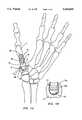
- FIG. 1Ais a schematic view, partially in section, of the human hand bone anatomy showing an artificial CMC joint embodying various features of the present invention in place therein.
- FIG. 1Bis a fragmentary enlarged view illustrating an alternative embodiment of the trapezium component of the joint shown in FIG. 1A.
- FIG. 2is a perspective view of the CMC joint of FIG. 1A shown in one position of articulation.
- FIG. 3is a view similar to FIG. 2 which shows the joint in another position of articulation.
- FIG. 4is a schematic perspective view which illustrates the individual elements of the joint shown in FIGS. 2 and 3 in association with two identical complementary toruses in order to illustrate how the two mating surfaces of the elements are generated, each being a surface portion of an appropriate torus.
- FIG. 5Ais a perspective view showing the two elements of FIGS. 2 and 3 in direct longitudinal alignment with each other, and FIGS. 5B-5D are longitudinal sectional views taken along the respective lines 5B--5B, 5C--5C and 5D--5D of FIG. 5A.
- the present inventionis directed to a joint prosthesis and to a method for the replacement of a diseased or damaged human joint.
- the preferred prosthesisis designed for permanent implantation in the human hand.
- the thumb of the human handowing to its particular opposing position and relative action to the other digits, forms a separate entity without which normal function of the hand is greatly compromised. Most importantly, the thumb is essential for the formation of a grip with each and all of the other fingers and in particular with the index finger. Functionality of the thumb is also essential for numerous other actions of the hand which require a universal-type joint, such as those which place the thumb in the vicinity of the plane of the palm.
- the unique function of the thumbis enabled by the special arrangement of its bony components and associated muscles.
- the first metacarpal 2 of the thumbis a fairly long bone, which has a hollow tubular shaft.
- the metacarpal bonehas articulating surfaces at each end.
- a carpometacarpal (CMC) replacement prosthetic joint 6(also referred to as the trapeziometacarpal joint) is located at the proximal end of the first metacarpal 2 with respect to the wrist, so that the first metacarpal 2 is articulated at the base of the thumb to the wrist trapezium 4 by an implanted prosthetic CMC joint 6.
- An axis of rotation between two bonesmay be defined as a line which does not move in relationship to either bone while they move around each other.
- the locations of the axes of rotation in the prosthetic CMC joint 6determine the positions the thumb can take.
- the CMC joint 6enables two axes of rotation as shown in FIG. 1A and thereby permits rotary motion in a manner which may be likened to an automotive universal joint.
- One axis 8is located in a trapezium element 14 and may lie in the plane of the paper for FIG. 1A.
- the other axis 10is located in a first metacarpal element 12; it lies in a plane that is perpendicular to the plane of the paper of FIG. 1A and also to the plane containing the axis 8.
- One axisis located on each side of the pair of facing articular surfaces that bear against each other and constitute the CMC joint, and the resultant shape of each is generally that of a saddle.
- the articular surfaces of the respective opposing native bonesalso have a natural saddle shape which enables rotation on each side of the joint, the natural human CMC joint does not have symmetric surfaces, and the axes of rotation are not perpendicular to each other. Movements of flexion and extension of the thumb at the CMC joint occur about the axis 8 passing through the trapezium element 14, i.e. the axis through the center of curvature of the convex surface at the end of the trapezium element.
- Movements of adduction and abduction of the thumb at the CMC jointoccur about the axis 10 passing through the metacarpal element 12, i.e. the axis through the center of curvature of the convex surface of the base or end of the metacarpal element 12.
- the CMC prosthetic joint 6as does the natural joint of the thumb, works by axial compression, i.e., one surface gliding on the other like a pivot. Abduction and adduction occur about a cone whose apex is volar and ulnar to the joint. This allows the metacarpal bone 2 to adopt any position in space whose direction can be altered by the contraction of muscles and ligaments. Articulation of this type, by rotation about the two axes simultaneously, is primarily responsible for the natural accurate positioning of the thumb in opposition to the fingers.
- the CMC prosthesis 6 of the present inventionallows substantially the same spatial motion as did the natural joint.
- the prosthesis 6allows fully functional anatomical articulation between the first metacarpal bone 2 and the wrist trapezium 4 into which the elements 12 and 14 are respectively implanted.
- the metacarpal element 12replaces the proximal portion of the first metacarpal bone 2
- the trapezium element 14replaces the adjacent articular contact portion of the trapezium 4.
- the two elementsmate in such a way as to form a pair of complementary articular surfaces which mimic those of the natural CMC joint. They have unique features which closely emulate the natural ease of motion of the thumb, and the design prolongs the life of the prosthesis by being subject to little wear.
- Articulating surfaces 24 and 25 of the prosthesisare provided at the ends of the metacarpal element 12 and the trapezium element 14, respectively; these surfaces are preferably defined by two complementary sections of surfaces of identical toruses each having a center hole diameter equal to the diameter of the tube, i.e. to the diameter of the circle that is revolved about an axis to generate a torus.
- FIG. 4schematically illustrates the relative locations on the toruses from which the toroidal surfaces 24 and 25 are generated.
- FIG. 4illustrates two identical toruses 16a and 16b each having a center hole with a diameter 20 equal to the diameter 22 of the circle that is revolved to create the torus.
- the articulating surfaces 24 and 25 of the elements 12 and 14are defined by such a two-torus arrangement.
- a pair of complementary surfaces 24, 25are obtained. They may both have the same peripheral outline as would be created by such an intersecting body; although they are preferably circular in their outline or profile, either could have a suitable alternative functional profile if desired.
- the articulating surfaces 24 and 25have surfaces that are sections of two identical toruses each having a tube diameter 22 which is the same as the diameter of the center hole 20. Under these conditions the mating articulating surfaces 24 and 25 will contact each other along two curved lines in the vertical and horizontal planes as shown in FIGS. 5B and 5D. Each line of contact is along the interior diameter of one torus and along a circumference of the tube of the other torus.
- the two lines of contact 28 and 30lie in the vertical and horizontal planes with the prosthesis in the orientation shown and are perpendicular to each other.
- the perpendicular, curved lines 28, 30 of physical contactare shown respectively in the horizontal sectional view 5D and in the vertical sectional view FIG. 5B.
- FIG. 5CA sectional view taken along a plane at 30 degrees from the horizontal axis is shown in FIG. 5C and exaggerated somewhat to show that, in such plane and all others except the 0° and 90° planes, there is only a single point of contact 31 located at the center where the two lines 28 and 30 in FIGS. 5D and 5B intersect.
- the surfaces 24 and 25are non-congruent and that open regions between the facing surfaces 24 and 25 provide for the passage of biological fluid for joint lubrication.
- the elements 12 and 14are preferably symmetrical about any centerline plane, as shown in FIGS. 5B-5D.
- a further important feature of the present joint 6is one which also is derived from the distinctive mutual contact only along the two perpendicular lines of contact.
- the available space 32 between two non-congruent surfaces 24 and 25 formed on the mating elements 12, 14, as shown in FIG. 5C,allows biological fluid to enter and thereby lubricate the area of articulation during use. This feature eliminates the condition of a "dry joint" which would have a tendency to result in high friction and wear as well as creating an uncomfortable grinding and/or "squeaky” sensation to the recipient.
- the facing articulating surfaces 24 and 25 of the metacarpal element 12 and the trapezium element 14may also be coated with a very thin coating of polyurethane, polyethylene or some other biocompatible polymeric resin to prevent site-specific bone ingrowth and to even further reduce friction, but which would not detract from the non-congruent character of the articular surfaces.
- the joint prosthesis elements 12, 14, and particularly the metacarpal element 12are preferably made of biocompatible materials having a modulus of elasticity in the range of that of natural living bone, e.g. a graphite substrate coated with pyrolytic carbon.
- the elements 12, 14are made of materials having a sufficient hardness such that they will not distend significantly under the normal load to which they will be expected to be subjected during use so that at least about 50% of the open space will remain between the articular surfaces even at full intended load.
- the amount of load to which the two surfaces would be normally subjectedis expected to be about 100 pounds.
- the materialsshould also exhibit good wear resistance so they will retain their original surface contours following years of implantation.
- Pyrocarbonsmeet these criteria, and examples of other suitable materials include biocompatible metal alloys such as chromium-cobalt alloys, e.g. Vitallium®, tantalum, titanium and molybdenum-base alloys, dense metal oxide ceramics such as aluminum oxide and zirconia oxide, and some highly dense, hard polymers.
- chromium-cobalt alloyse.g. Vitallium®, tantalum, titanium and molybdenum-base alloys
- dense metal oxide ceramicssuch as aluminum oxide and zirconia oxide
- some highly dense, hard polymerssome highly dense, hard polymers.
- both of the elements 12, 14are preferably made from the same hard biocompatible material, one component might be made from a chromium-cobalt alloy and the other from a hard ultra high molecular weight polyethylene.
- the elements 12 and 14are made from pyrolytic carbon having a DPH of at least 200 (Diamond Pyramid Hardness using a 50 gram load) or an equivalent material which would
- the metacarpal element 12is preferably constructed with an intramedullary stem portion 34 of the CMC joint prosthesis that may be slightly tapered to fit more easily into the long hollow tubular shaft of the metacarpal bone 2 and is provided with a plurality of undercuts and grooves 35 in its outer surface to promote the primary stabilizing ingrowth of bone in these regions.
- the metacarpalis a long bone having a medullary tubular shaft, and a cavity 36 is prepared by hollowing out this region to accommodate the intramedullary stem 34 of the metacarpal element 12, permitting it to be inserted and anchored in the medullary cavity 36 as shown in FIG. 1.
- the intramedullary stem portion 34may be made of a material different from the portion which defines the surface 24, e.g.
- the desired medullary cavity 36is preferably shaped during surgery, using a special broach, to achieve a snug fit with the stem portion 34 of the metacarpal element 12.
- the intramedullary stem portion 34 of the metacarpal element 12can be secured within the cavity 36 using one of several methods, such as: 1) bone growth into a porous coating or undulating surface of the intramedullary stem 34, 2) use of bone cement, 3) bonding of the intramedullary stem 34 to the first metacarpal bone 2 by means of a surface-active stem coating such as hydroxyapatite, or 4) a tight mechanical fit of the stem within the medullary cavity 36.
- the trapezium 4is a generally nugget-shaped bone and does not allow for accommodation of a long intramedullary stem.
- the trapezium element 14could be attached to the trapezium bone using only an arrangement similar to items 1-4 described supra for the metacarpal element 12.
- the base 38 of the trapezium element 14is preferably shaped to interfit with a complementary cavity formed in that specific bone, and actual attachment may be via a multitude of different interengagements such as are known to those skilled in this art. Attachment may be assisted by inter alia, bone cement, tissue ingrowth, bonding to active materials such as hydroxyapatite, mechanical interlocking or a combination of any of these.
- Irregularities on the surface of the base 38can be used to enhance attachment.
- the use of a mortise joint configuration at the base 38 of the trapeziumis one preferred embodiment for attachment of the trapezium element 14.
- Special tools and techniquesare available to those skilled in this art to cut a proper mortise groove in the trapezium 4 that will receive and snugly mate with a complementary tenon 39 that has been shaped at the base 38 of the trapezium element 14 as shown in FIG. 1A.
- FIG. 1AIn another preferred embodiment shown in FIG.
- the base 38a of the trapezium element 14ais a hemispherically shaped portion 40 located below a pair of grooves, which base is fit into a similar cup-shaped cavity 41 created in the trapezium 14 using bone cement if desired.
- Spike-shaped protrusions or interlocking key shapescan also be used to enhance mechanical stability.
- Very generally standard methodsmay be used to attach the respective trapezium element 14 and metacarpal element 12 of the prosthetic joint 6 to the trapezium 4 and first metacarpal bone 2 of the thumb (see, e.g. Ferrari, B. et al., The Journal of Bone and joint Surgery, vol. 68-A:8, 1117-1184 (1986)).
- the trapezium element 14is positioned in the trapezium 4 so that the axis of rotation 8 defined by the curvature of the saddle surface 25 of the trapezium element provides for the desired flexion and extension movements of the thumb, i.e. having the orientation seen in FIG. 1A.
- This positioning of the trapezium element 14generally also locates the perpendicular axis of rotation through the curvature of the convex surface 24 of the mating metacarpal element 12, which in turn provides for the adduction and abduction movements of the thumb.
- the prosthetic joint 6allows compound angular movement between the metacarpal bone 2 and the trapezium bone 4 from the straight-ahead or in-line orientation illustrated in FIG. 1A and in FIG. 5A.
- FIG. 2the displacement of the metacarpal element 12 with respect to the trapezium element 14 is shown as would occur when the angular orientation of the metacarpal bone relative to the trapezium bone is changed in one plane.
- FIG. 3illustrates a further sequential displacement of the two elements 12, 14 in a plane perpendicular thereto completing the compound movement. It can be seen that the articular saddle surfaces 24 and 25 accommodate such movement; thus, the prosthetic joint 6 having two such interengaging surfaces of this shape has many advantages.
Landscapes
- Health & Medical Sciences (AREA)
- Engineering & Computer Science (AREA)
- Orthopedic Medicine & Surgery (AREA)
- Vascular Medicine (AREA)
- Animal Behavior & Ethology (AREA)
- Oral & Maxillofacial Surgery (AREA)
- Biomedical Technology (AREA)
- Heart & Thoracic Surgery (AREA)
- Cardiology (AREA)
- Life Sciences & Earth Sciences (AREA)
- Transplantation (AREA)
- General Health & Medical Sciences (AREA)
- Public Health (AREA)
- Veterinary Medicine (AREA)
- Physics & Mathematics (AREA)
- Geometry (AREA)
- Manufacturing & Machinery (AREA)
- Prostheses (AREA)
Abstract
Description
Claims (10)
Priority Applications (8)
| Application Number | Priority Date | Filing Date | Title |
|---|---|---|---|
| US08/531,150US5645605A (en) | 1995-09-18 | 1995-09-18 | Implant device to replace the carpometacarpal joint of the human thumb |
| AT96931607TATE187318T1 (en) | 1995-09-18 | 1996-09-16 | IMPLANT DEVICE FOR REPLACING THE CARPOMETACARPAL JOINT OF THE HUMAN THUMB |
| EP96931607AEP0854695B1 (en) | 1995-09-18 | 1996-09-16 | Implant device to replace the carpometacarpal joint of the human thumb |
| CA002232068ACA2232068C (en) | 1995-09-18 | 1996-09-16 | Implant device to replace the carpometacarpal joint of the human thumb |
| ES96931607TES2141533T3 (en) | 1995-09-18 | 1996-09-16 | IMPLANT FOR CARPOMETACARPANIC JOINT OF THE THUMB. |
| PCT/US1996/014857WO1997010780A1 (en) | 1995-09-18 | 1996-09-16 | Implant device to replace the carpometacarpal joint of the human thumb |
| JP51282197AJP3578771B2 (en) | 1995-09-18 | 1996-09-16 | Implant device for carpal metacarpal replacement of the thumb of the human body |
| DE69605564TDE69605564T2 (en) | 1995-09-18 | 1996-09-16 | IMPLANT DEVICE FOR REPLACING THE CARPOMETIC CARPAL JOINT OF THE HUMAN THUMB |
Applications Claiming Priority (1)
| Application Number | Priority Date | Filing Date | Title |
|---|---|---|---|
| US08/531,150US5645605A (en) | 1995-09-18 | 1995-09-18 | Implant device to replace the carpometacarpal joint of the human thumb |
Publications (1)
| Publication Number | Publication Date |
|---|---|
| US5645605Atrue US5645605A (en) | 1997-07-08 |
Family
ID=24116454
Family Applications (1)
| Application Number | Title | Priority Date | Filing Date |
|---|---|---|---|
| US08/531,150Expired - LifetimeUS5645605A (en) | 1995-09-18 | 1995-09-18 | Implant device to replace the carpometacarpal joint of the human thumb |
Country Status (8)
| Country | Link |
|---|---|
| US (1) | US5645605A (en) |
| EP (1) | EP0854695B1 (en) |
| JP (1) | JP3578771B2 (en) |
| AT (1) | ATE187318T1 (en) |
| CA (1) | CA2232068C (en) |
| DE (1) | DE69605564T2 (en) |
| ES (1) | ES2141533T3 (en) |
| WO (1) | WO1997010780A1 (en) |
Cited By (67)
| Publication number | Priority date | Publication date | Assignee | Title |
|---|---|---|---|---|
| US5938700A (en)* | 1998-02-11 | 1999-08-17 | Engineering Consulting Services, Inc. | Constrained prosthesis for replacement of joints between long bones in the hand |
| US6126690A (en)* | 1996-07-03 | 2000-10-03 | The Trustees Of Columbia University In The City Of New York | Anatomically correct prosthesis and method and apparatus for manufacturing prosthesis |
| US6398815B1 (en) | 2000-01-30 | 2002-06-04 | Diamicron, Inc. | Prosthetic joint having at least one superhard articulation surface |
| US6410877B1 (en) | 2000-01-30 | 2002-06-25 | Diamicron, Inc. | Methods for shaping and finishing prosthetic joint components including polycrystalline diamond compacts |
| US6425922B1 (en) | 2000-01-30 | 2002-07-30 | Diamicron, Inc. | Prosthetic hip joint having at least one sintered polycrystalline diamond compact articulation surface |
| US6488715B1 (en) | 2000-01-30 | 2002-12-03 | Diamicron, Inc. | Diamond-surfaced cup for use in a prosthetic joint |
| US6494918B1 (en) | 2000-01-30 | 2002-12-17 | Diamicron, Inc. | Component for a prosthetic joint having a diamond load bearing and articulation surface |
| US6514289B1 (en) | 2000-01-30 | 2003-02-04 | Diamicron, Inc. | Diamond articulation surface for use in a prosthetic joint |
| US6596225B1 (en) | 2000-01-31 | 2003-07-22 | Diamicron, Inc. | Methods for manufacturing a diamond prosthetic joint component |
| US6676704B1 (en) | 1994-08-12 | 2004-01-13 | Diamicron, Inc. | Prosthetic joint component having at least one sintered polycrystalline diamond compact articulation surface and substrate surface topographical features in said polycrystalline diamond compact |
| US6699292B2 (en) | 2000-11-28 | 2004-03-02 | Ascension Orthopedics, Inc. | Interphalangeal joint replacement |
| US6709463B1 (en) | 2000-01-30 | 2004-03-23 | Diamicron, Inc. | Prosthetic joint component having at least one solid polycrystalline diamond component |
| WO2004026186A1 (en)* | 2002-09-18 | 2004-04-01 | Mathys Medizinaltechnik Ag | Implant comprising a two-piece joint |
| EP1437104A1 (en)* | 2003-01-07 | 2004-07-14 | Ascension Orthopedics, Inc. | Carpometacarpal joint prosthesis |
| US20040176774A1 (en)* | 2003-03-06 | 2004-09-09 | Rafail Zubok | Instrumentation and methods for use in implanting a cervical disc replacement device |
| US6793681B1 (en) | 1994-08-12 | 2004-09-21 | Diamicron, Inc. | Prosthetic hip joint having a polycrystalline diamond articulation surface and a plurality of substrate layers |
| US20040193272A1 (en)* | 2003-03-06 | 2004-09-30 | Rafail Zubok | Instrumentation and methods for use in implanting a cervical disc replacement device |
| WO2004093767A1 (en)* | 2003-04-18 | 2004-11-04 | Ascension Orthopedics, Inc. | Interpositional biarticular disk implant |
| US20050055095A1 (en)* | 2001-07-16 | 2005-03-10 | Errico Joseph P. | Artificial intervertebral disc trials having a cylindrical engagement surface |
| US20050165487A1 (en)* | 2004-01-28 | 2005-07-28 | Muhanna Nabil L. | Artificial intervertebral disc |
| US20050228497A1 (en)* | 2002-04-23 | 2005-10-13 | Ferree Bret A | Artificial disc replacements with natural kinematics |
| US20050251265A1 (en)* | 2004-05-07 | 2005-11-10 | Calandruccio James H | Trapezium implant for thumb and method |
| US20060069446A1 (en)* | 2004-09-21 | 2006-03-30 | Ragusa Mathieu A J | Articular interposition implant |
| US20070118221A1 (en)* | 2002-10-04 | 2007-05-24 | Zimmer Trabecular Metal Technology, Inc. | Prosthetic disc and vertebral body replacement device having pyrolytic carbon bearing members |
| US20070123993A1 (en)* | 2001-12-12 | 2007-05-31 | Bioprofile | Trapezal or trapezo-metacarpal implant |
| US20070123985A1 (en)* | 2005-05-27 | 2007-05-31 | Spinecore, Inc. | Intervertebral disc and insertion methods therefor |
| US7396501B2 (en) | 1994-08-12 | 2008-07-08 | Diamicron, Inc. | Use of gradient layers and stress modifiers to fabricate composite constructs |
| US7396505B2 (en) | 1994-08-12 | 2008-07-08 | Diamicron, Inc. | Use of CoCrMo to augment biocompatibility in polycrystalline diamond compacts |
| US20080249631A1 (en)* | 2005-11-17 | 2008-10-09 | Bioprofile | Implant, more particularly partial ulnar head implant |
| US20080255501A1 (en)* | 2007-04-10 | 2008-10-16 | Michael Hogendijk | Percutaneous delivery and retrieval systems for shape-changing orthopedic joint devices |
| US20080255664A1 (en)* | 2007-04-10 | 2008-10-16 | Mdesign International | Percutaneously deliverable orthopedic joint device |
| US20090012612A1 (en)* | 2007-04-10 | 2009-01-08 | David White | Devices and methods for push-delivery of implants |
| US20090228106A1 (en)* | 2008-03-06 | 2009-09-10 | Peter Strzepa | Implants and Methods of Use |
| US20100004657A1 (en)* | 2008-01-18 | 2010-01-07 | Spinecore, Inc. | Instruments and methods for inserting artificial intervertebral implants |
| US20100004743A1 (en)* | 2008-07-03 | 2010-01-07 | Fellowship of Orthopaedic Researchers, LLC | Talar implants and methods of use |
| US20100057132A1 (en)* | 2008-09-03 | 2010-03-04 | Mimedx Inc., Corporation of the State of Florida | Modular bone fixation device for treatment of fractures and related methods |
| US20100057214A1 (en)* | 2008-09-03 | 2010-03-04 | Mimedx, Inc., Corporation of the State of Florida | Arthrodesis implant for finger joints and related methods |
| US20100057215A1 (en)* | 2008-09-03 | 2010-03-04 | Mimedx Inc. | Arthroplastic implant with anchor peg for basilar joint and related methods |
| US20100057213A1 (en)* | 2008-09-03 | 2010-03-04 | Mimedx Inc., Corporation of the State of Florida | Arthroplastic implant with shield for basilar joint and related methods |
| WO2010033691A2 (en) | 2008-09-17 | 2010-03-25 | Ascension Orthopedics, Inc. | Thumb metacarpal implant |
| US7713302B2 (en) | 2001-10-01 | 2010-05-11 | Spinecore, Inc. | Intervertebral spacer device utilizing a spirally slotted belleville washer having radially spaced concentric grooves |
| US20100168864A1 (en)* | 2008-09-12 | 2010-07-01 | Articulinx, Inc. | Tensioned delivery of orthopedic joint device |
| US20100241233A1 (en)* | 2002-04-12 | 2010-09-23 | Spinecore, Inc. | Spacerless artificial disc replacements |
| US20100268345A1 (en)* | 2001-10-01 | 2010-10-21 | Spinecore, Inc. | Intervertebral spacer device |
| US20100312348A1 (en)* | 2009-06-04 | 2010-12-09 | Howmedica Osteonics Corp. | Orthopedic paek-on-polymer bearings |
| US20110087297A1 (en)* | 2009-10-14 | 2011-04-14 | Skeletal Dynamics Llc | Internal joint stabilizer for a multi-axis joint, such as a carpo-metacarpal joint or the like, and method of use |
| US20110224790A1 (en)* | 2009-09-11 | 2011-09-15 | Articulinx, Inc. | Disc-based orthopedic devices |
| US8021431B1 (en)* | 1999-07-14 | 2011-09-20 | Biopro, Inc. | Modular basal thumb joint implant |
| US8029568B2 (en) | 2001-10-18 | 2011-10-04 | Spinecore, Inc. | Intervertebral spacer device having a slotted partial circular domed arch strip spring |
| US8038713B2 (en) | 2002-04-23 | 2011-10-18 | Spinecore, Inc. | Two-component artificial disc replacements |
| WO2011149936A2 (en) | 2010-05-24 | 2011-12-01 | Skeletal Dynamics Llc | Devices, implements and methods for the treatment of a multi-axis joint |
| US20120158139A1 (en)* | 2010-12-17 | 2012-06-21 | Bio2 Technologies, Inc. | Method and Apparatus for a Porous Orthopedic Implant |
| US20120158153A1 (en)* | 2009-06-23 | 2012-06-21 | Replication Medical Inc. | Trapezium prosthesis |
| US8690956B2 (en) | 2010-08-23 | 2014-04-08 | Fellowship Of Orthopaedic Researchers, Inc. | Talar implants and methods of use |
| US8734491B2 (en) | 2011-08-24 | 2014-05-27 | Instratek, Inc. | Method and apparatus for the stabilization of the trapeziometacarpal joint |
| US8852286B2 (en) | 2009-08-25 | 2014-10-07 | Fellowship Of Orthopaedic Researchers, Inc. | Trochlear implants and methods of use |
| US8858644B2 (en) | 2009-01-08 | 2014-10-14 | Memometal Technologies | Orthopaedic implant for arthroplasty of the fingers |
| US20150265745A1 (en)* | 2014-03-18 | 2015-09-24 | Globus Medical, Inc | Porous and Nonporous Materials for Tissue Grafting and Repair |
| US20150342745A1 (en)* | 2014-06-02 | 2015-12-03 | Stryker European Holdings I, Llc | Metacarpal rod anchor for a trapezometacarpal prosthesis |
| US20150374503A1 (en)* | 2014-06-30 | 2015-12-31 | Bacterin International, Inc. | Implant for fusion between adjacent bone bodies |
| US20160166373A9 (en)* | 2005-10-25 | 2016-06-16 | Globus Medical, Inc | Porous and nonporous materials for tissue grafting and repair |
| US9486322B2 (en) | 2012-06-19 | 2016-11-08 | Christopher Sterling Pallia | Carpometacarpal prosthesis system and method of using same |
| EP3636226A1 (en)* | 2015-03-31 | 2020-04-15 | Cartiva, Inc. | Carpometacarpal (cmc) implants |
| US11547579B2 (en) | 2018-06-21 | 2023-01-10 | Arthrosurface, Inc. | Systems and methods for sizing and introduction of soft-tissue allografts |
| US11642226B2 (en) | 2020-05-01 | 2023-05-09 | Ensemble Orthopedics, Inc. | Implantable interpositional orthopedic pain management |
| US11944550B2 (en) | 2015-12-30 | 2024-04-02 | Arthrosurface, Inc. | System and method for non-binding allograft subtalar joint implant |
| US12290443B2 (en) | 2020-05-01 | 2025-05-06 | Ensemble Orthopedics, Inc. | Implantable interpositional orthopedic pain management |
Families Citing this family (5)
| Publication number | Priority date | Publication date | Assignee | Title |
|---|---|---|---|---|
| FR2805151B1 (en)* | 2000-02-21 | 2003-08-15 | Cremascolli Ortho S A | TRAPEZO-METACARPIEN PROSTHESIS WITH IMPROVED MOBILITY |
| US7625408B2 (en) | 2003-07-22 | 2009-12-01 | Avanta Orthopaedics, Llc | Prosthetic wrist implant |
| US7160331B2 (en) | 2004-12-01 | 2007-01-09 | Mayo Foundation For Medical Research And Education | Sigmoid notch implant |
| WO2012154920A1 (en) | 2011-05-12 | 2012-11-15 | Small Bone Innovations, Inc. | Wrist implant for carpal hemiarthroplasty |
| DE102014115301A1 (en)* | 2014-10-21 | 2016-04-21 | HandImplants GmbH | Carpometacarpal joint implant |
Citations (14)
| Publication number | Priority date | Publication date | Assignee | Title |
|---|---|---|---|---|
| US4021864A (en)* | 1976-04-14 | 1977-05-10 | The Regents Of The University Of California | Ankle prosthesis |
| US4131957A (en)* | 1977-08-12 | 1979-01-02 | General Atomic Company | Ball and socket prosthetic joint |
| US4231121A (en)* | 1979-07-05 | 1980-11-04 | Wright Dow Corning | Metacarpal-phalangeal prosthesis |
| US4242759A (en)* | 1979-03-12 | 1981-01-06 | Ontario Research Foundation | M.C.P. Joint replacement |
| US4276660A (en)* | 1979-05-25 | 1981-07-07 | Laure Prosthetics, Inc. | Carpometacarpal thumb joint |
| US4459708A (en)* | 1979-07-10 | 1984-07-17 | Bernard Buttazzoni | Joint prosthesis |
| US4642122A (en)* | 1986-04-02 | 1987-02-10 | Laure Prosthetics, Inc. | Toe implant |
| US4908031A (en)* | 1989-07-27 | 1990-03-13 | Dow Corning Wright | Toe implant |
| US4955916A (en)* | 1989-05-01 | 1990-09-11 | Techmedica, Inc. | Thumb joint prosthesis |
| US5037440A (en)* | 1989-06-06 | 1991-08-06 | Koenig Implant, Inc. | Orthopedic toe implant |
| US5092896A (en)* | 1989-09-28 | 1992-03-03 | Protek Ag | Finger joint prosthesis |
| FR2670109A1 (en)* | 1990-10-15 | 1992-06-12 | Lacaffiniere Jean Yves De | Total trapeziometacarpal prosthesis with intermediate component |
| DE4412721A1 (en)* | 1993-04-15 | 1994-10-20 | Tornier Une S A Francaise Ets | Carpometacarpal prosthesis |
| US5405400A (en)* | 1993-10-05 | 1995-04-11 | Orthomet, Inc. | Joint prosthesis enabling rotary circumduction |
Family Cites Families (3)
| Publication number | Priority date | Publication date | Assignee | Title |
|---|---|---|---|---|
| US4126924A (en)* | 1977-02-07 | 1978-11-28 | General Atomic Company | Socket and joint prostheses |
| FR2633824B1 (en)* | 1988-07-07 | 1991-04-12 | Lesur Etienne | PROSTHETIC PIECE FOR WRIST |
| US5522900A (en)* | 1993-12-17 | 1996-06-04 | Avanta Orthopaedics | Prosthetic joint and method of manufacture |
- 1995
- 1995-09-18USUS08/531,150patent/US5645605A/ennot_activeExpired - Lifetime
- 1996
- 1996-09-16CACA002232068Apatent/CA2232068C/ennot_activeExpired - Fee Related
- 1996-09-16WOPCT/US1996/014857patent/WO1997010780A1/enactiveIP Right Grant
- 1996-09-16DEDE69605564Tpatent/DE69605564T2/ennot_activeExpired - Lifetime
- 1996-09-16ESES96931607Tpatent/ES2141533T3/ennot_activeExpired - Lifetime
- 1996-09-16EPEP96931607Apatent/EP0854695B1/ennot_activeExpired - Lifetime
- 1996-09-16ATAT96931607Tpatent/ATE187318T1/ennot_activeIP Right Cessation
- 1996-09-16JPJP51282197Apatent/JP3578771B2/ennot_activeExpired - Fee Related
Patent Citations (14)
| Publication number | Priority date | Publication date | Assignee | Title |
|---|---|---|---|---|
| US4021864A (en)* | 1976-04-14 | 1977-05-10 | The Regents Of The University Of California | Ankle prosthesis |
| US4131957A (en)* | 1977-08-12 | 1979-01-02 | General Atomic Company | Ball and socket prosthetic joint |
| US4242759A (en)* | 1979-03-12 | 1981-01-06 | Ontario Research Foundation | M.C.P. Joint replacement |
| US4276660A (en)* | 1979-05-25 | 1981-07-07 | Laure Prosthetics, Inc. | Carpometacarpal thumb joint |
| US4231121A (en)* | 1979-07-05 | 1980-11-04 | Wright Dow Corning | Metacarpal-phalangeal prosthesis |
| US4459708A (en)* | 1979-07-10 | 1984-07-17 | Bernard Buttazzoni | Joint prosthesis |
| US4642122A (en)* | 1986-04-02 | 1987-02-10 | Laure Prosthetics, Inc. | Toe implant |
| US4955916A (en)* | 1989-05-01 | 1990-09-11 | Techmedica, Inc. | Thumb joint prosthesis |
| US5037440A (en)* | 1989-06-06 | 1991-08-06 | Koenig Implant, Inc. | Orthopedic toe implant |
| US4908031A (en)* | 1989-07-27 | 1990-03-13 | Dow Corning Wright | Toe implant |
| US5092896A (en)* | 1989-09-28 | 1992-03-03 | Protek Ag | Finger joint prosthesis |
| FR2670109A1 (en)* | 1990-10-15 | 1992-06-12 | Lacaffiniere Jean Yves De | Total trapeziometacarpal prosthesis with intermediate component |
| DE4412721A1 (en)* | 1993-04-15 | 1994-10-20 | Tornier Une S A Francaise Ets | Carpometacarpal prosthesis |
| US5405400A (en)* | 1993-10-05 | 1995-04-11 | Orthomet, Inc. | Joint prosthesis enabling rotary circumduction |
Cited By (183)
| Publication number | Priority date | Publication date | Assignee | Title |
|---|---|---|---|---|
| US6676704B1 (en) | 1994-08-12 | 2004-01-13 | Diamicron, Inc. | Prosthetic joint component having at least one sintered polycrystalline diamond compact articulation surface and substrate surface topographical features in said polycrystalline diamond compact |
| US6800095B1 (en) | 1994-08-12 | 2004-10-05 | Diamicron, Inc. | Diamond-surfaced femoral head for use in a prosthetic joint |
| US7077867B1 (en) | 1994-08-12 | 2006-07-18 | Diamicron, Inc. | Prosthetic knee joint having at least one diamond articulation surface |
| US7396501B2 (en) | 1994-08-12 | 2008-07-08 | Diamicron, Inc. | Use of gradient layers and stress modifiers to fabricate composite constructs |
| US7396505B2 (en) | 1994-08-12 | 2008-07-08 | Diamicron, Inc. | Use of CoCrMo to augment biocompatibility in polycrystalline diamond compacts |
| US6793681B1 (en) | 1994-08-12 | 2004-09-21 | Diamicron, Inc. | Prosthetic hip joint having a polycrystalline diamond articulation surface and a plurality of substrate layers |
| US6126690A (en)* | 1996-07-03 | 2000-10-03 | The Trustees Of Columbia University In The City Of New York | Anatomically correct prosthesis and method and apparatus for manufacturing prosthesis |
| US6459948B1 (en) | 1996-07-03 | 2002-10-01 | The Trustees Of Columbia University In The City Of New York | Anatomically correct prosthesis and method and apparatus for manufacturing prosthesis |
| US5938700A (en)* | 1998-02-11 | 1999-08-17 | Engineering Consulting Services, Inc. | Constrained prosthesis for replacement of joints between long bones in the hand |
| US8021431B1 (en)* | 1999-07-14 | 2011-09-20 | Biopro, Inc. | Modular basal thumb joint implant |
| US6425922B1 (en) | 2000-01-30 | 2002-07-30 | Diamicron, Inc. | Prosthetic hip joint having at least one sintered polycrystalline diamond compact articulation surface |
| US6517583B1 (en) | 2000-01-30 | 2003-02-11 | Diamicron, Inc. | Prosthetic hip joint having a polycrystalline diamond compact articulation surface and a counter bearing surface |
| US6709463B1 (en) | 2000-01-30 | 2004-03-23 | Diamicron, Inc. | Prosthetic joint component having at least one solid polycrystalline diamond component |
| US6514289B1 (en) | 2000-01-30 | 2003-02-04 | Diamicron, Inc. | Diamond articulation surface for use in a prosthetic joint |
| US6494918B1 (en) | 2000-01-30 | 2002-12-17 | Diamicron, Inc. | Component for a prosthetic joint having a diamond load bearing and articulation surface |
| US6488715B1 (en) | 2000-01-30 | 2002-12-03 | Diamicron, Inc. | Diamond-surfaced cup for use in a prosthetic joint |
| US6410877B1 (en) | 2000-01-30 | 2002-06-25 | Diamicron, Inc. | Methods for shaping and finishing prosthetic joint components including polycrystalline diamond compacts |
| US6398815B1 (en) | 2000-01-30 | 2002-06-04 | Diamicron, Inc. | Prosthetic joint having at least one superhard articulation surface |
| US6596225B1 (en) | 2000-01-31 | 2003-07-22 | Diamicron, Inc. | Methods for manufacturing a diamond prosthetic joint component |
| US6699292B2 (en) | 2000-11-28 | 2004-03-02 | Ascension Orthopedics, Inc. | Interphalangeal joint replacement |
| US8357167B2 (en) | 2001-07-16 | 2013-01-22 | Spinecore, Inc. | Artificial intervertebral disc trials with baseplates having inward tool engagement holes |
| US20100174371A9 (en)* | 2001-07-16 | 2010-07-08 | Errico Joseph P | Artificial intervertebral disc trials having a cylindrical engagement surface |
| US20050055095A1 (en)* | 2001-07-16 | 2005-03-10 | Errico Joseph P. | Artificial intervertebral disc trials having a cylindrical engagement surface |
| US20100268345A1 (en)* | 2001-10-01 | 2010-10-21 | Spinecore, Inc. | Intervertebral spacer device |
| US8092539B2 (en) | 2001-10-01 | 2012-01-10 | Spinecore, Inc. | Intervertebral spacer device having a belleville washer with concentric grooves |
| US7713302B2 (en) | 2001-10-01 | 2010-05-11 | Spinecore, Inc. | Intervertebral spacer device utilizing a spirally slotted belleville washer having radially spaced concentric grooves |
| US8029568B2 (en) | 2001-10-18 | 2011-10-04 | Spinecore, Inc. | Intervertebral spacer device having a slotted partial circular domed arch strip spring |
| US20070123993A1 (en)* | 2001-12-12 | 2007-05-31 | Bioprofile | Trapezal or trapezo-metacarpal implant |
| US10271956B2 (en)* | 2002-04-12 | 2019-04-30 | Spinecore, Inc. | Spacerless artificial disc replacements |
| US20140148906A1 (en)* | 2002-04-12 | 2014-05-29 | Spinecore, Inc. | Spacerless artificial disc replacements |
| US10786363B2 (en) | 2002-04-12 | 2020-09-29 | Spinecore, Inc. | Spacerless artificial disc replacements |
| US9198773B2 (en)* | 2002-04-12 | 2015-12-01 | Spinecore, Inc. | Spacerless artificial disc replacements |
| US8277507B2 (en) | 2002-04-12 | 2012-10-02 | Spinecore, Inc. | Spacerless artificial disc replacements |
| US20100241233A1 (en)* | 2002-04-12 | 2010-09-23 | Spinecore, Inc. | Spacerless artificial disc replacements |
| US20160045329A1 (en)* | 2002-04-12 | 2016-02-18 | Spinecore, Inc. | Spacerless artificial disc replacements |
| US9572679B2 (en) | 2002-04-23 | 2017-02-21 | Spinecore, Inc. | Artificial disc replacements with natural kinematics |
| US20050228497A1 (en)* | 2002-04-23 | 2005-10-13 | Ferree Bret A | Artificial disc replacements with natural kinematics |
| US8038713B2 (en) | 2002-04-23 | 2011-10-18 | Spinecore, Inc. | Two-component artificial disc replacements |
| US9168146B2 (en) | 2002-04-23 | 2015-10-27 | Spinecore, Inc. | Artificial disc replacements with natural kinematics |
| US10299933B2 (en) | 2002-04-23 | 2019-05-28 | Spinecore, Inc. | Artificial disc replacements with natural kinematics |
| US8366772B2 (en) | 2002-04-23 | 2013-02-05 | Spinecore, Inc. | Artificial disc replacements with natural kinematics |
| US9877841B2 (en) | 2002-04-23 | 2018-01-30 | Spinecore, Inc. | Artificial disc replacements with natural kinematics |
| US8092540B2 (en) | 2002-09-18 | 2012-01-10 | Synthes Usa, Llc | Implant comprising a two-piece joint |
| AU2002322984B2 (en)* | 2002-09-18 | 2006-06-22 | Synthes Gmbh | Implant comprising a two-piece joint |
| US20090204217A1 (en)* | 2002-09-18 | 2009-08-13 | Daniel Baumgartner | Implant comprising a two-piece joint |
| WO2004026186A1 (en)* | 2002-09-18 | 2004-04-01 | Mathys Medizinaltechnik Ag | Implant comprising a two-piece joint |
| US7749272B2 (en)* | 2002-10-04 | 2010-07-06 | Zimmer Trabecular Metal Technology, Inc. | Prosthetic disc and vertebral body replacement device having pyrolytic carbon bearing members |
| USD720071S1 (en) | 2002-10-04 | 2014-12-23 | Bruce H. Robie | Vertebral implant |
| US20070118221A1 (en)* | 2002-10-04 | 2007-05-24 | Zimmer Trabecular Metal Technology, Inc. | Prosthetic disc and vertebral body replacement device having pyrolytic carbon bearing members |
| US20050033426A1 (en)* | 2003-01-07 | 2005-02-10 | Ogilvie William F. | Carpometacarpal joint prosthesis |
| EP1437104A1 (en)* | 2003-01-07 | 2004-07-14 | Ascension Orthopedics, Inc. | Carpometacarpal joint prosthesis |
| US7641696B2 (en) | 2003-01-07 | 2010-01-05 | Ascension Orthopedics, Inc. | Carpometacarpal joint prosthesis |
| US7641665B2 (en) | 2003-03-06 | 2010-01-05 | Spinecore, Inc. | Instrumentation and methods for use in implementing a cervical disc replacement device |
| US20040176772A1 (en)* | 2003-03-06 | 2004-09-09 | Rafail Zubok | Instrumentation and methods for use in implanting a cervical disc replacement device |
| US20040176845A1 (en)* | 2003-03-06 | 2004-09-09 | Rafail Zubok | Cervical disc replacement |
| US20040176847A1 (en)* | 2003-03-06 | 2004-09-09 | Rafail Zubok | Cervical disc replacement method |
| US7198643B2 (en) | 2003-03-06 | 2007-04-03 | Spinecore, Inc. | Cervical disc replacement |
| US6997955B2 (en) | 2003-03-06 | 2006-02-14 | Spinecore, Inc. | Cervical disc replacement |
| US6997954B2 (en) | 2003-03-06 | 2006-02-14 | Spinecore, Inc. | Cervical disc replacement method |
| US20040176850A1 (en)* | 2003-03-06 | 2004-09-09 | Rafail Zubok | Cervical disc replacement |
| US7226452B2 (en) | 2003-03-06 | 2007-06-05 | Spinecore, Inc. | Instrumentation and methods for use in implanting a cervical disc replacement device |
| US20040176849A1 (en)* | 2003-03-06 | 2004-09-09 | Rafail Zubok | Cervical disc replacement |
| US20040176843A1 (en)* | 2003-03-06 | 2004-09-09 | Rafail Zubok | Instrumentation and methods for use in implanting a cervical disc replacement device |
| US20040176848A1 (en)* | 2003-03-06 | 2004-09-09 | Rafail Zubok | Cervical disc replacement method |
| US20040176776A1 (en)* | 2003-03-06 | 2004-09-09 | Rafail Zubok | Instrumentation and methods for use in implanting a cervical disc replacement device |
| US8231628B2 (en) | 2003-03-06 | 2012-07-31 | Spinecore, Inc. | Instrumentation and methods for use in implanting a cervical disc replacement device |
| US20040176852A1 (en)* | 2003-03-06 | 2004-09-09 | Rafail Zubok | Instrumentation and methods for use in implanting a cervical disc replacement device |
| US8936640B2 (en) | 2003-03-06 | 2015-01-20 | Spinecore, Inc. | Cervical disc replacement |
| US6994729B2 (en) | 2003-03-06 | 2006-02-07 | Spinecore, Inc. | Cervical disc replacement |
| US9028552B2 (en) | 2003-03-06 | 2015-05-12 | Spinecore, Inc. | Cervical disc replacement |
| US20040176846A1 (en)* | 2003-03-06 | 2004-09-09 | Rafail Zubok | Cervical disc replacement |
| US7618439B2 (en) | 2003-03-06 | 2009-11-17 | Spinecore, Inc. | Instrumentation and methods for use in implanting a cervical disc replacement device |
| US7637911B2 (en) | 2003-03-06 | 2009-12-29 | Spinecore, Inc. | Instrumentation and methods for use in implanting a cervical disc replacement device |
| US20040176851A1 (en)* | 2003-03-06 | 2004-09-09 | Rafail Zubok | Cervical disc replacement |
| US6994728B2 (en) | 2003-03-06 | 2006-02-07 | Spinecore, Inc. | Cervical disc replacement method |
| US7641654B2 (en) | 2003-03-06 | 2010-01-05 | Spinecore, Inc. | Instrumentation and methods for use in implanting a cervical disc replacement device |
| US8109979B2 (en) | 2003-03-06 | 2012-02-07 | Spinecore, Inc. | Instrumentation and methods for use in implanting a cervical disc replacement device |
| US6972038B2 (en) | 2003-03-06 | 2005-12-06 | Spinecore, Inc. | Cervical disc replacement |
| US7648511B2 (en) | 2003-03-06 | 2010-01-19 | Spinecore, Inc. | Instrumentation and methods for use in implanting a cervical disc replacement device |
| US7662182B2 (en) | 2003-03-06 | 2010-02-16 | Spinecore, Inc. | Instrumentation and methods for use in implanting a cervical disc replacement device |
| US6972037B2 (en) | 2003-03-06 | 2005-12-06 | Spinecore, Inc. | Cervical disc replacement |
| US20040176778A1 (en)* | 2003-03-06 | 2004-09-09 | Rafail Zubok | Instrumentation and methods for use in implanting a cervical disc replacement device |
| US20040193272A1 (en)* | 2003-03-06 | 2004-09-30 | Rafail Zubok | Instrumentation and methods for use in implanting a cervical disc replacement device |
| US20040176773A1 (en)* | 2003-03-06 | 2004-09-09 | Rafail Zubok | Instrumentation and methods for use in implanting a cervical disc replacement device |
| US7674292B2 (en) | 2003-03-06 | 2010-03-09 | Spinecore, Inc. | Instrumentation and methods for use in implanting a cervical disc replacement device |
| US20040220590A1 (en)* | 2003-03-06 | 2004-11-04 | Rafail Zubok | Instrumentation and methods for use in implanting a cervical disc replacement device |
| US7708780B2 (en) | 2003-03-06 | 2010-05-04 | Spinecore, Inc. | Instrumentation and methods for use in implanting a cervical disc replacement device |
| US20050240272A1 (en)* | 2003-03-06 | 2005-10-27 | Spinecore, Inc. | Cervical disc replacement |
| US20050240271A1 (en)* | 2003-03-06 | 2005-10-27 | Spinecore, Inc. | Cervical disc replacement |
| US20040176844A1 (en)* | 2003-03-06 | 2004-09-09 | Rafail Zubok | Cervical disc replacement |
| US20050071013A1 (en)* | 2003-03-06 | 2005-03-31 | Spinecore, Inc. | Instrumentation and methods for use in implanting a cervical disc replacement device |
| US6896676B2 (en) | 2003-03-06 | 2005-05-24 | Spinecore, Inc. | Instrumentation and methods for use in implanting a cervical disc replacement device |
| US20040176774A1 (en)* | 2003-03-06 | 2004-09-09 | Rafail Zubok | Instrumentation and methods for use in implanting a cervical disc replacement device |
| US6908484B2 (en) | 2003-03-06 | 2005-06-21 | Spinecore, Inc. | Cervical disc replacement |
| US7837739B2 (en)* | 2003-04-18 | 2010-11-23 | Ascension Orthopedics, Inc. | Interpositional biarticular disk implant |
| US20060241778A1 (en)* | 2003-04-18 | 2006-10-26 | Ascension Orthopedics, Inc. | Interpositional biarticular disk implant |
| AU2004232009B2 (en)* | 2003-04-18 | 2009-08-06 | Ascension Orthopedics, Inc. | Interpositional biarticular disk implant |
| WO2004093767A1 (en)* | 2003-04-18 | 2004-11-04 | Ascension Orthopedics, Inc. | Interpositional biarticular disk implant |
| US20050165487A1 (en)* | 2004-01-28 | 2005-07-28 | Muhanna Nabil L. | Artificial intervertebral disc |
| US8066773B2 (en) | 2004-01-28 | 2011-11-29 | F3 Technologies, Llc | Artificial intervertebral disc |
| US20050251265A1 (en)* | 2004-05-07 | 2005-11-10 | Calandruccio James H | Trapezium implant for thumb and method |
| US20060069446A1 (en)* | 2004-09-21 | 2006-03-30 | Ragusa Mathieu A J | Articular interposition implant |
| US9539114B2 (en) | 2005-05-27 | 2017-01-10 | Spinecore, Inc. | Instruments and methods for inserting artificial intervertebral implants |
| US9782272B2 (en) | 2005-05-27 | 2017-10-10 | Spinecore, Inc. | Intervertebral disc and insertion methods therefor |
| US20070123985A1 (en)* | 2005-05-27 | 2007-05-31 | Spinecore, Inc. | Intervertebral disc and insertion methods therefor |
| US8777959B2 (en) | 2005-05-27 | 2014-07-15 | Spinecore, Inc. | Intervertebral disc and insertion methods therefor |
| US9526634B2 (en) | 2005-05-27 | 2016-12-27 | Spinecore, Inc. | Intervertebral disc and insertion methods therefor |
| US9226837B2 (en) | 2005-05-27 | 2016-01-05 | Spinecore, Inc. | Intervertebral disc and insertion methods therefor |
| US9095451B2 (en) | 2005-05-27 | 2015-08-04 | Spinecore, Inc. | Intervertebral disc and insertion methods therefor |
| US10213322B2 (en) | 2005-05-27 | 2019-02-26 | Spinecore, Inc. | Intervertebral disc and insertion methods therefor |
| US10245154B2 (en) | 2005-05-27 | 2019-04-02 | Spinecore, Inc. | Instruments and methods for inserting artificial intervertebral implants |
| US9622882B2 (en) | 2005-05-27 | 2017-04-18 | Spinecore, Inc. | Intervertebral disc and insertion methods therefor |
| US11642231B2 (en) | 2005-05-27 | 2023-05-09 | Howmedica Osteonics Corp. | Intervertebral disc and insertion methods therefor |
| US10835389B2 (en) | 2005-05-27 | 2020-11-17 | Howmedica Osteonics Corp. | Intervertebral disc and insertion methods therefor |
| US20160166373A9 (en)* | 2005-10-25 | 2016-06-16 | Globus Medical, Inc | Porous and nonporous materials for tissue grafting and repair |
| US10105207B2 (en)* | 2005-10-25 | 2018-10-23 | Globus Medical, Inc. | Porous and nonporous materials for tissue grafting and repair |
| US8088168B2 (en) | 2005-11-17 | 2012-01-03 | Tornier Sas | Implant, more particularly partial ulnar head implant |
| US20080249631A1 (en)* | 2005-11-17 | 2008-10-09 | Bioprofile | Implant, more particularly partial ulnar head implant |
| US20090012612A1 (en)* | 2007-04-10 | 2009-01-08 | David White | Devices and methods for push-delivery of implants |
| US20080255664A1 (en)* | 2007-04-10 | 2008-10-16 | Mdesign International | Percutaneously deliverable orthopedic joint device |
| US20080255501A1 (en)* | 2007-04-10 | 2008-10-16 | Michael Hogendijk | Percutaneous delivery and retrieval systems for shape-changing orthopedic joint devices |
| US8357203B2 (en) | 2007-04-10 | 2013-01-22 | Articulinx, Inc. | Suture-based orthopedic joint devices |
| US20110029094A1 (en)* | 2007-04-10 | 2011-02-03 | Articulinx, Inc. | Retrieval of orthopedic joint device |
| US20100004657A1 (en)* | 2008-01-18 | 2010-01-07 | Spinecore, Inc. | Instruments and methods for inserting artificial intervertebral implants |
| US8579911B2 (en) | 2008-01-18 | 2013-11-12 | Spinecore, Inc. | Instruments and methods for inserting artificial intervertebral implants |
| US20100121451A1 (en)* | 2008-03-06 | 2010-05-13 | Peter Strzepa | Cartilage Implants and Methods of Use |
| US8177842B2 (en) | 2008-03-06 | 2012-05-15 | Moirai Orthopaedics, Llc | Implants and methods of use |
| US8092530B2 (en) | 2008-03-06 | 2012-01-10 | Moirai Orthopedics, Llc | Cartilage implants |
| US8152847B2 (en) | 2008-03-06 | 2012-04-10 | Moirai Orthopaedics, Llc | Methods of use of cartilage implants |
| US20090228106A1 (en)* | 2008-03-06 | 2009-09-10 | Peter Strzepa | Implants and Methods of Use |
| US8591581B2 (en) | 2008-03-06 | 2013-11-26 | Moirai Orthopedics, Llc | Methods of use of cartilage implants |
| US20090228104A1 (en)* | 2008-03-06 | 2009-09-10 | Peter Strzepa | Cartilage implants and methods of use |
| US20100121452A1 (en)* | 2008-03-06 | 2010-05-13 | Peter Strzepa | Methods of Use of Cartilage Implants |
| US8043375B2 (en) | 2008-03-06 | 2011-10-25 | MoiRai Orthopaedic, LLC | Cartilage implants |
| US8876901B2 (en) | 2008-03-06 | 2014-11-04 | Moirai Orthopaedics, Llc | Articular cartilage implants |
| US8876902B2 (en) | 2008-03-06 | 2014-11-04 | Moirai Orthopaedics, Llc | Methods of articular cartilage implants |
| US20100004743A1 (en)* | 2008-07-03 | 2010-01-07 | Fellowship of Orthopaedic Researchers, LLC | Talar implants and methods of use |
| US8012217B2 (en) | 2008-07-03 | 2011-09-06 | Fellowship of Orthopaedic Researchers, LLC | Talar implants and methods of use |
| US20100057132A1 (en)* | 2008-09-03 | 2010-03-04 | Mimedx Inc., Corporation of the State of Florida | Modular bone fixation device for treatment of fractures and related methods |
| US8231625B2 (en) | 2008-09-03 | 2012-07-31 | The Cleveland Clinic Foundation | Modular bone fixation device for treatment of fractures and related methods |
| US20100057213A1 (en)* | 2008-09-03 | 2010-03-04 | Mimedx Inc., Corporation of the State of Florida | Arthroplastic implant with shield for basilar joint and related methods |
| US8343228B2 (en) | 2008-09-03 | 2013-01-01 | The Cleveland Clinic Foundation | Arthroplastic implant with anchor peg for basilar joint and related methods |
| US20100057214A1 (en)* | 2008-09-03 | 2010-03-04 | Mimedx, Inc., Corporation of the State of Florida | Arthrodesis implant for finger joints and related methods |
| US8506641B2 (en) | 2008-09-03 | 2013-08-13 | The Cleveland Clinic Foundation | Arthrodesis implant for finger joints and related methods |
| US20100057215A1 (en)* | 2008-09-03 | 2010-03-04 | Mimedx Inc. | Arthroplastic implant with anchor peg for basilar joint and related methods |
| US8167952B2 (en) | 2008-09-03 | 2012-05-01 | The Cleveland Clinic Foundation | Arthroplastic implant with shield for basilar joint and related methods |
| US20100168864A1 (en)* | 2008-09-12 | 2010-07-01 | Articulinx, Inc. | Tensioned delivery of orthopedic joint device |
| WO2010033691A2 (en) | 2008-09-17 | 2010-03-25 | Ascension Orthopedics, Inc. | Thumb metacarpal implant |
| US8858644B2 (en) | 2009-01-08 | 2014-10-14 | Memometal Technologies | Orthopaedic implant for arthroplasty of the fingers |
| US9907660B2 (en) | 2009-06-04 | 2018-03-06 | Howmedica Osteonics Corp. | Orthopedic paek-on-polymer bearings |
| US12076246B2 (en) | 2009-06-04 | 2024-09-03 | Howmedica Osteonics Corp. | Orthopedic PAEK-on-polymer bearings |
| US20100312348A1 (en)* | 2009-06-04 | 2010-12-09 | Howmedica Osteonics Corp. | Orthopedic paek-on-polymer bearings |
| US20120158153A1 (en)* | 2009-06-23 | 2012-06-21 | Replication Medical Inc. | Trapezium prosthesis |
| US8920499B2 (en) | 2009-08-25 | 2014-12-30 | Fellowship Of Orthopaedic Researchers, Inc. | Method of use of trochlear implants |
| US9668865B2 (en) | 2009-08-25 | 2017-06-06 | Fellowship Of Orthopaedic Researchers, Inc. | Trochlear implants and methods of use |
| US8852286B2 (en) | 2009-08-25 | 2014-10-07 | Fellowship Of Orthopaedic Researchers, Inc. | Trochlear implants and methods of use |
| US20110224790A1 (en)* | 2009-09-11 | 2011-09-15 | Articulinx, Inc. | Disc-based orthopedic devices |
| US8292954B2 (en) | 2009-09-11 | 2012-10-23 | Articulinx, Inc. | Disc-based orthopedic devices |
| US8292955B2 (en) | 2009-09-11 | 2012-10-23 | Articulinx, Inc. | Disc-shaped orthopedic devices |
| US8764830B2 (en) | 2009-09-11 | 2014-07-01 | Articulinx, Inc. | Disc-shaped orthopedic devices |
| WO2011047151A3 (en)* | 2009-10-14 | 2011-06-16 | Skeletal Dynamics Llc | Internal joint stabilizer for a multi-axis joint, such as a carpo-metacarpal joint or the like, and method of use |
| US20110087297A1 (en)* | 2009-10-14 | 2011-04-14 | Skeletal Dynamics Llc | Internal joint stabilizer for a multi-axis joint, such as a carpo-metacarpal joint or the like, and method of use |
| US8900239B2 (en) | 2009-10-14 | 2014-12-02 | Skeletal Dynamics, Llc. | Internal joint stabilizer for a multi-axis joint, such as a carpo-metacarpal joint or the like, and method of use |
| WO2011149936A2 (en) | 2010-05-24 | 2011-12-01 | Skeletal Dynamics Llc | Devices, implements and methods for the treatment of a multi-axis joint |
| US9173691B2 (en) | 2010-05-24 | 2015-11-03 | Skeletal Dynamics Llc | Devices, implements and methods for the treatment of a multi-axis joint |
| US8690956B2 (en) | 2010-08-23 | 2014-04-08 | Fellowship Of Orthopaedic Researchers, Inc. | Talar implants and methods of use |
| US20120158139A1 (en)* | 2010-12-17 | 2012-06-21 | Bio2 Technologies, Inc. | Method and Apparatus for a Porous Orthopedic Implant |
| WO2012082989A3 (en)* | 2010-12-17 | 2012-10-26 | Bio2 Technologies, Inc. | Method and apparatus for a porous orthopedic implant |
| US9918711B2 (en) | 2011-08-24 | 2018-03-20 | Howmedica Osteonics Corp. | Method and apparatus for the stabilization of the trapeziometacarpal joint |
| US8734491B2 (en) | 2011-08-24 | 2014-05-27 | Instratek, Inc. | Method and apparatus for the stabilization of the trapeziometacarpal joint |
| US9486322B2 (en) | 2012-06-19 | 2016-11-08 | Christopher Sterling Pallia | Carpometacarpal prosthesis system and method of using same |
| US20150265745A1 (en)* | 2014-03-18 | 2015-09-24 | Globus Medical, Inc | Porous and Nonporous Materials for Tissue Grafting and Repair |
| US20150342745A1 (en)* | 2014-06-02 | 2015-12-03 | Stryker European Holdings I, Llc | Metacarpal rod anchor for a trapezometacarpal prosthesis |
| US9597192B2 (en)* | 2014-06-02 | 2017-03-21 | Stryker European Holdings I, Llc | Metacarpal rod anchor for a trapezometacarpal prosthesis |
| US20150374503A1 (en)* | 2014-06-30 | 2015-12-31 | Bacterin International, Inc. | Implant for fusion between adjacent bone bodies |
| US10758374B2 (en) | 2015-03-31 | 2020-09-01 | Cartiva, Inc. | Carpometacarpal (CMC) implants and methods |
| US11839552B2 (en) | 2015-03-31 | 2023-12-12 | Cartiva, Inc. | Carpometacarpal (CMC) implants and methods |
| EP3636226A1 (en)* | 2015-03-31 | 2020-04-15 | Cartiva, Inc. | Carpometacarpal (cmc) implants |
| US11944550B2 (en) | 2015-12-30 | 2024-04-02 | Arthrosurface, Inc. | System and method for non-binding allograft subtalar joint implant |
| US11547579B2 (en) | 2018-06-21 | 2023-01-10 | Arthrosurface, Inc. | Systems and methods for sizing and introduction of soft-tissue allografts |
| US11642226B2 (en) | 2020-05-01 | 2023-05-09 | Ensemble Orthopedics, Inc. | Implantable interpositional orthopedic pain management |
| US12290443B2 (en) | 2020-05-01 | 2025-05-06 | Ensemble Orthopedics, Inc. | Implantable interpositional orthopedic pain management |
| US12290448B2 (en) | 2020-05-01 | 2025-05-06 | Ensemble Orthopedics, Inc. | Implantable interpositional orthopedic pain management |
Also Published As
| Publication number | Publication date |
|---|---|
| ES2141533T3 (en) | 2000-03-16 |
| JP3578771B2 (en) | 2004-10-20 |
| CA2232068A1 (en) | 1997-03-27 |
| DE69605564D1 (en) | 2000-01-13 |
| JP2000510351A (en) | 2000-08-15 |
| EP0854695B1 (en) | 1999-12-08 |
| DE69605564T2 (en) | 2000-07-13 |
| CA2232068C (en) | 2006-11-28 |
| EP0854695A1 (en) | 1998-07-29 |
| ATE187318T1 (en) | 1999-12-15 |
| WO1997010780A1 (en) | 1997-03-27 |
Similar Documents
| Publication | Publication Date | Title |
|---|---|---|
| US5645605A (en) | Implant device to replace the carpometacarpal joint of the human thumb | |
| AU680559B2 (en) | Joint prosthesis enabling rotary circumduction | |
| US6159247A (en) | Metacarpal-phalangeal joint replacement | |
| US4106128A (en) | Endoprosthetic bone joint | |
| US11974926B2 (en) | Prosthesis surface treatment for soft tissue attachment thereto | |
| US5593445A (en) | Bi-axial prosthetic joint | |
| US6689169B2 (en) | Prothesis | |
| US6217616B1 (en) | Elbow prosthesis | |
| US4352212A (en) | Joint prosthesis | |
| US4280231A (en) | Elbow prosthesis | |
| AU683100B2 (en) | Prosthesis for replacement of joints between long bones in the hand | |
| EP1350488A2 (en) | Wrist prosthesis | |
| JPH01107757A (en) | Prosthetics for metacarpal finger or knuckle joint | |
| US5728163A (en) | Phalangeal joint prosthesis | |
| GB2269752A (en) | Anatomic wrist | |
| US5938700A (en) | Constrained prosthesis for replacement of joints between long bones in the hand | |
| JP2012502750A (en) | Thumb metacarpal implant | |
| Roberts et al. | Design considerations for total wrist arthroplasty |
Legal Events
| Date | Code | Title | Description |
|---|---|---|---|
| AS | Assignment | Owner name:ASCENSION ORTHOPEDICS, INC., TEXAS Free format text:ASSIGNMENT OF ASSIGNORS INTEREST;ASSIGNOR:KLAWITTER, JEROME J.;REEL/FRAME:008300/0998 Effective date:19961203 | |
| STCF | Information on status: patent grant | Free format text:PATENTED CASE | |
| FEPP | Fee payment procedure | Free format text:PAYOR NUMBER ASSIGNED (ORIGINAL EVENT CODE: ASPN); ENTITY STATUS OF PATENT OWNER: SMALL ENTITY | |
| FPAY | Fee payment | Year of fee payment:4 | |
| FPAY | Fee payment | Year of fee payment:8 | |
| AS | Assignment | Owner name:SILICON VALLEY BANK, CALIFORNIA Free format text:SECURITY INTEREST;ASSIGNOR:ASCENSION ORTHOPEDICS, INC.;REEL/FRAME:016206/0570 Effective date:20050112 | |
| AS | Assignment | Owner name:SILICON VALLEY BANK, TEXAS Free format text:SECURITY AGREEMENT;ASSIGNOR:ASCENSION ORTHOPEDICS, INC.;REEL/FRAME:018552/0937 Effective date:20061127 | |
| AS | Assignment | Owner name:ASCENSION ORTHOPEDICS, INC., TEXAS Free format text:RELEASE;ASSIGNOR:SILICON VALLEY BANK;REEL/FRAME:020532/0947 Effective date:20080211 | |
| AS | Assignment | Owner name:ASCENSION ORTHOPEDICS, INC., TEXAS Free format text:RELEASE;ASSIGNOR:SILICON VALLEY BANK;REEL/FRAME:020571/0841 Effective date:20080211 | |
| FPAY | Fee payment | Year of fee payment:12 | |
| AS | Assignment | Owner name:OXFORD FINANCE CORPORATION, AS AGENT AND AS A LEND Free format text:SECURITY AGREEMENT;ASSIGNOR:ASCENSION ORTHOPEDICS, INC.;REEL/FRAME:025192/0543 Effective date:20100917 | |
| AS | Assignment | Owner name:ASCENSION ORTHOPEDICS, INC., TEXAS Free format text:RELEASE BY SECURED PARTY;ASSIGNOR:OXFORD FINANCE, LLC;REEL/FRAME:026967/0211 Effective date:20110923 |