US5645114A - Dispensing assembly with interchangeable cartridge pumps - Google Patents
Dispensing assembly with interchangeable cartridge pumpsDownload PDFInfo
- Publication number
- US5645114A US5645114AUS08/251,597US25159794AUS5645114AUS 5645114 AUS5645114 AUS 5645114AUS 25159794 AUS25159794 AUS 25159794AUS 5645114 AUS5645114 AUS 5645114A
- Authority
- US
- United States
- Prior art keywords
- slide
- rotor
- reagent
- dispensing
- slides
- Prior art date
- Legal status (The legal status is an assumption and is not a legal conclusion. Google has not performed a legal analysis and makes no representation as to the accuracy of the status listed.)
- Expired - Lifetime
Links
- 239000003153chemical reaction reagentSubstances0.000claimsabstractdescription80
- 239000007788liquidSubstances0.000claimsabstractdescription54
- 239000012530fluidSubstances0.000claimsdescription14
- 238000010438heat treatmentMethods0.000claimsdescription7
- 239000012487rinsing solutionSubstances0.000claimsdescription5
- 230000007723transport mechanismEffects0.000claimsdescription5
- 238000004891communicationMethods0.000claimsdescription4
- 239000000243solutionSubstances0.000claimsdescription4
- 230000006835compressionEffects0.000abstractdescription6
- 238000007906compressionMethods0.000abstractdescription6
- 239000000463materialSubstances0.000abstract1
- 239000013256coordination polymerSubstances0.000description13
- 229920001971elastomerPolymers0.000description10
- 238000010276constructionMethods0.000description6
- 230000005484gravityEffects0.000description5
- 239000004033plasticSubstances0.000description5
- 229920003023plasticPolymers0.000description5
- 230000008901benefitEffects0.000description4
- 238000005096rolling processMethods0.000description4
- 230000037452primingEffects0.000description3
- 238000005086pumpingMethods0.000description3
- 230000002269spontaneous effectEffects0.000description3
- 230000009471actionEffects0.000description2
- 238000005336crackingMethods0.000description2
- 230000003247decreasing effectEffects0.000description2
- 239000000806elastomerSubstances0.000description2
- 230000007246mechanismEffects0.000description2
- 238000000034methodMethods0.000description2
- 230000003252repetitive effectEffects0.000description2
- 238000000926separation methodMethods0.000description2
- 229920002379silicone rubberPolymers0.000description2
- 244000043261Hevea brasiliensisSpecies0.000description1
- 239000000853adhesiveSubstances0.000description1
- 230000001070adhesive effectEffects0.000description1
- 230000008859changeEffects0.000description1
- 238000011109contaminationMethods0.000description1
- 238000012864cross contaminationMethods0.000description1
- 230000000994depressogenic effectEffects0.000description1
- 230000000694effectsEffects0.000description1
- 230000005611electricityEffects0.000description1
- 230000007613environmental effectEffects0.000description1
- 238000001704evaporationMethods0.000description1
- 230000008020evaporationEffects0.000description1
- 230000001744histochemical effectEffects0.000description1
- 238000002955isolationMethods0.000description1
- 239000000314lubricantSubstances0.000description1
- 239000002184metalSubstances0.000description1
- 238000012986modificationMethods0.000description1
- 230000004048modificationEffects0.000description1
- 229920003052natural elastomerPolymers0.000description1
- 229920001194natural rubberPolymers0.000description1
- 230000002572peristaltic effectEffects0.000description1
- 235000019271petrolatumNutrition0.000description1
- 229920001296polysiloxanePolymers0.000description1
- 229920002635polyurethanePolymers0.000description1
- 239000004814polyurethaneSubstances0.000description1
- 239000004800polyvinyl chlorideSubstances0.000description1
- 238000003825pressingMethods0.000description1
- 238000007789sealingMethods0.000description1
- 239000004945silicone rubberSubstances0.000description1
- 125000000391vinyl groupChemical group[H]C([*])=C([H])[H]0.000description1
- 229920002554vinyl polymerPolymers0.000description1
Images


Classifications
- G—PHYSICS
- G01—MEASURING; TESTING
- G01N—INVESTIGATING OR ANALYSING MATERIALS BY DETERMINING THEIR CHEMICAL OR PHYSICAL PROPERTIES
- G01N35/00—Automatic analysis not limited to methods or materials provided for in any single one of groups G01N1/00 - G01N33/00; Handling materials therefor
- G01N35/10—Devices for transferring samples or any liquids to, in, or from, the analysis apparatus, e.g. suction devices, injection devices
- G01N35/1002—Reagent dispensers
- B—PERFORMING OPERATIONS; TRANSPORTING
- B01—PHYSICAL OR CHEMICAL PROCESSES OR APPARATUS IN GENERAL
- B01L—CHEMICAL OR PHYSICAL LABORATORY APPARATUS FOR GENERAL USE
- B01L3/00—Containers or dishes for laboratory use, e.g. laboratory glassware; Droppers
- B01L3/02—Burettes; Pipettes
- B01L3/0289—Apparatus for withdrawing or distributing predetermined quantities of fluid
- B01L3/0293—Apparatus for withdrawing or distributing predetermined quantities of fluid for liquids
- B—PERFORMING OPERATIONS; TRANSPORTING
- B05—SPRAYING OR ATOMISING IN GENERAL; APPLYING FLUENT MATERIALS TO SURFACES, IN GENERAL
- B05B—SPRAYING APPARATUS; ATOMISING APPARATUS; NOZZLES
- B05B11/00—Single-unit hand-held apparatus in which flow of contents is produced by the muscular force of the operator at the moment of use
- B05B11/0005—Components or details
- B05B11/0062—Outlet valves actuated by the pressure of the fluid to be sprayed
- B05B11/007—Outlet valves actuated by the pressure of the fluid to be sprayed being opened by deformation of a sealing element made of resiliently deformable material, e.g. flaps, skirts, duck-bill valves
- B—PERFORMING OPERATIONS; TRANSPORTING
- B05—SPRAYING OR ATOMISING IN GENERAL; APPLYING FLUENT MATERIALS TO SURFACES, IN GENERAL
- B05B—SPRAYING APPARATUS; ATOMISING APPARATUS; NOZZLES
- B05B11/00—Single-unit hand-held apparatus in which flow of contents is produced by the muscular force of the operator at the moment of use
- B05B11/0005—Components or details
- B05B11/0062—Outlet valves actuated by the pressure of the fluid to be sprayed
- B05B11/0072—A valve member forming part of an outlet opening
- B—PERFORMING OPERATIONS; TRANSPORTING
- B05—SPRAYING OR ATOMISING IN GENERAL; APPLYING FLUENT MATERIALS TO SURFACES, IN GENERAL
- B05B—SPRAYING APPARATUS; ATOMISING APPARATUS; NOZZLES
- B05B11/00—Single-unit hand-held apparatus in which flow of contents is produced by the muscular force of the operator at the moment of use
- B05B11/01—Single-unit hand-held apparatus in which flow of contents is produced by the muscular force of the operator at the moment of use characterised by the means producing the flow
- B05B11/10—Pump arrangements for transferring the contents from the container to a pump chamber by a sucking effect and forcing the contents out through the dispensing nozzle
- B05B11/1028—Pumps having a pumping chamber with a deformable wall
- B05B11/1032—Pumps having a pumping chamber with a deformable wall actuated without substantial movement of the nozzle in the direction of the pressure stroke
- B—PERFORMING OPERATIONS; TRANSPORTING
- B67—OPENING, CLOSING OR CLEANING BOTTLES, JARS OR SIMILAR CONTAINERS; LIQUID HANDLING
- B67D—DISPENSING, DELIVERING OR TRANSFERRING LIQUIDS, NOT OTHERWISE PROVIDED FOR
- B67D7/00—Apparatus or devices for transferring liquids from bulk storage containers or reservoirs into vehicles or into portable containers, e.g. for retail sale purposes
- B67D7/02—Apparatus or devices for transferring liquids from bulk storage containers or reservoirs into vehicles or into portable containers, e.g. for retail sale purposes for transferring liquids other than fuel or lubricants
- B67D7/0216—Apparatus or devices for transferring liquids from bulk storage containers or reservoirs into vehicles or into portable containers, e.g. for retail sale purposes for transferring liquids other than fuel or lubricants by squeezing collapsible or flexible storage containers
- F—MECHANICAL ENGINEERING; LIGHTING; HEATING; WEAPONS; BLASTING
- F04—POSITIVE - DISPLACEMENT MACHINES FOR LIQUIDS; PUMPS FOR LIQUIDS OR ELASTIC FLUIDS
- F04B—POSITIVE-DISPLACEMENT MACHINES FOR LIQUIDS; PUMPS
- F04B23/00—Pumping installations or systems
- F04B23/02—Pumping installations or systems having reservoirs
- F04B23/025—Pumping installations or systems having reservoirs the pump being located directly adjacent the reservoir
- F—MECHANICAL ENGINEERING; LIGHTING; HEATING; WEAPONS; BLASTING
- F04—POSITIVE - DISPLACEMENT MACHINES FOR LIQUIDS; PUMPS FOR LIQUIDS OR ELASTIC FLUIDS
- F04B—POSITIVE-DISPLACEMENT MACHINES FOR LIQUIDS; PUMPS
- F04B43/00—Machines, pumps, or pumping installations having flexible working members
- F04B43/08—Machines, pumps, or pumping installations having flexible working members having tubular flexible members
- F—MECHANICAL ENGINEERING; LIGHTING; HEATING; WEAPONS; BLASTING
- F04—POSITIVE - DISPLACEMENT MACHINES FOR LIQUIDS; PUMPS FOR LIQUIDS OR ELASTIC FLUIDS
- F04B—POSITIVE-DISPLACEMENT MACHINES FOR LIQUIDS; PUMPS
- F04B53/00—Component parts, details or accessories not provided for in, or of interest apart from, groups F04B1/00 - F04B23/00 or F04B39/00 - F04B47/00
- F04B53/10—Valves; Arrangement of valves
- F04B53/1037—Flap valves
- F04B53/1047—Flap valves the valve being formed by one or more flexible elements
- F04B53/106—Flap valves the valve being formed by one or more flexible elements the valve being a membrane
- F04B53/1067—Flap valves the valve being formed by one or more flexible elements the valve being a membrane fixed at its whole periphery and with an opening at its centre
- F04B53/107—Flap valves the valve being formed by one or more flexible elements the valve being a membrane fixed at its whole periphery and with an opening at its centre the opening normally being closed by a fixed element
- F—MECHANICAL ENGINEERING; LIGHTING; HEATING; WEAPONS; BLASTING
- F16—ENGINEERING ELEMENTS AND UNITS; GENERAL MEASURES FOR PRODUCING AND MAINTAINING EFFECTIVE FUNCTIONING OF MACHINES OR INSTALLATIONS; THERMAL INSULATION IN GENERAL
- F16K—VALVES; TAPS; COCKS; ACTUATING-FLOATS; DEVICES FOR VENTING OR AERATING
- F16K15/00—Check valves
- F16K15/14—Check valves with flexible valve members
- F16K15/144—Check valves with flexible valve members the closure elements being fixed along all or a part of their periphery
- B—PERFORMING OPERATIONS; TRANSPORTING
- B05—SPRAYING OR ATOMISING IN GENERAL; APPLYING FLUENT MATERIALS TO SURFACES, IN GENERAL
- B05B—SPRAYING APPARATUS; ATOMISING APPARATUS; NOZZLES
- B05B11/00—Single-unit hand-held apparatus in which flow of contents is produced by the muscular force of the operator at the moment of use
- B05B11/01—Single-unit hand-held apparatus in which flow of contents is produced by the muscular force of the operator at the moment of use characterised by the means producing the flow
- B05B11/10—Pump arrangements for transferring the contents from the container to a pump chamber by a sucking effect and forcing the contents out through the dispensing nozzle
- B05B11/1042—Components or details
- B05B11/1066—Pump inlet valves
- B05B11/1067—Pump inlet valves actuated by pressure
- G—PHYSICS
- G01—MEASURING; TESTING
- G01N—INVESTIGATING OR ANALYSING MATERIALS BY DETERMINING THEIR CHEMICAL OR PHYSICAL PROPERTIES
- G01N1/00—Sampling; Preparing specimens for investigation
- G01N1/28—Preparing specimens for investigation including physical details of (bio-)chemical methods covered elsewhere, e.g. G01N33/50, C12Q
- G01N1/30—Staining; Impregnating ; Fixation; Dehydration; Multistep processes for preparing samples of tissue, cell or nucleic acid material and the like for analysis
- G01N1/31—Apparatus therefor
- G01N1/312—Apparatus therefor for samples mounted on planar substrates
- G—PHYSICS
- G01—MEASURING; TESTING
- G01N—INVESTIGATING OR ANALYSING MATERIALS BY DETERMINING THEIR CHEMICAL OR PHYSICAL PROPERTIES
- G01N35/00—Automatic analysis not limited to methods or materials provided for in any single one of groups G01N1/00 - G01N33/00; Handling materials therefor
- G01N35/02—Automatic analysis not limited to methods or materials provided for in any single one of groups G01N1/00 - G01N33/00; Handling materials therefor using a plurality of sample containers moved by a conveyor system past one or more treatment or analysis stations
- G01N35/04—Details of the conveyor system
- G01N2035/0439—Rotary sample carriers, i.e. carousels
- G01N2035/0443—Rotary sample carriers, i.e. carousels for reagents
- G—PHYSICS
- G01—MEASURING; TESTING
- G01N—INVESTIGATING OR ANALYSING MATERIALS BY DETERMINING THEIR CHEMICAL OR PHYSICAL PROPERTIES
- G01N35/00—Automatic analysis not limited to methods or materials provided for in any single one of groups G01N1/00 - G01N33/00; Handling materials therefor
- G01N35/10—Devices for transferring samples or any liquids to, in, or from, the analysis apparatus, e.g. suction devices, injection devices
- G01N35/1009—Characterised by arrangements for controlling the aspiration or dispense of liquids
- G01N35/1016—Control of the volume dispensed or introduced
Definitions
- This inventionrelates to a pump mechanism for dispensing small aliquots of a fluid, such as a biological reagent. It may serve as part of an apparatus which dispenses a plurality of reagents to be dispensed in small volumes.
- syringe pumpsPumping systems using a syringe housing
- the syringeis first filled with a liquid.
- the liquidcan then be accurately dispensed by applying a precise pressure on the plunger, usually by an electromechanical actuator.
- the distance that the plunger is depresseddirectly controls the amount of fluid to be dispensed.
- Such syringe pumpshave two advantages: 1) the absence of tubing lines leading into and out of a pump which must be primed and flushed, and 2) a separation of the wetted components from the electromechanical controlling elements.
- Such syringe pumpsare useful in situations where repetitive dispensing of precise amounts of liquid are required.
- a drawback of such syringe pumpsis that interchanging syringes on a single electromechanical actuator requires that the actuator mechanism be realigned with the position of the syringe plunger that is being inserted.
- the need for repetitive manual intervention to align the electromechanical actuator with the position of the syringe plungeris a disadvantage. This disadvantage will be more acutely felt in a dispensing instrument with many electromechanical actuators.
- a cartridge pump in accordance with the present inventionmay be used as a component of a movable platform containing a plurality of electromechanical actuators.
- the present inventionincludes a rotor containing reagents and a rotor containing slides that rotate on the same axis.
- a single actuatoris located on a station enabling the slides to be accessed by the reagents.
- the cartridgescan be easily replaced with different cartridges using the same electromechanical actuators without the need for aligning electromechanical actuators with the cartridges. This aspect increases the versatility of the dispensing instrument as a whole.
- a pump cartridgecomprises a reagent reservoir for containing a liquid.
- the reservoirhas a liquid flow outlet at the bottom thereof.
- a metering chamberis directly connected to the liquid flow outlet of the reagent reservoir.
- the metering chambercomprises a compressible housing having a noncompressed shape.
- a one-way inlet valve and a one-way outlet valveare provided at respective ends of the compressible housing and are aligned in the same direction to allow unidirectional flow from the reservoir through the housing.
- the compressible housingmay be compressed for the unidirectional ejection of a volume of liquid from the metering chamber.
- the compressible housingreturns to the noncompressed shape after cessation of compression to draw an additional volume of liquid into the metering chamber.
- a pump cartridge framemay hold the pump cartridge in a fixed position with respect to an actuator capable of compressing the compressible housing of the pump cartridge.
- the actuatoris an electromechanical actuator.
- the dispensing assemblymay be mounted on a moveable platform for dispensing various reagents in various sample cells.
- a plurality of electromechanical actuatorsare positioned adjacent to a plurality of receptacles on the frame into which a plurality of pump cartridges can be fit.
- the cartridgemay have one or more ridges extending outwardly from its external surface to serve as keys in grooves in a supporting frame. Cartridges may be coded by the circumferential positions of ridges to assure that cartridges containing particular reagents are inserted in appropriate locations in the frame.
- a dispensing assemblycomprises an assembly base and a slide rotor adapted to carry a plurality of microscope slides holding tissue samples.
- This slide rotoris capable of rotating on the assembly base.
- a reagent rotoradapted to carry a plurality of different reagents sits above the slide rotor and is also capable of rotating on the assembly base.
- slide framesare provided for holding the slides in the slide rotor.
- the slide framesare radially insertable into the slide rotor.
- These slide framesthemselves comprise a slide frame base adapted to support a plurality of slides and containing resistive heating units for heating each one of these slides.
- a thermocouplecan also be provided to detect the temperature of the slides as heated by the resistive heating units.
- a slide frame housingis adapted to sealably fit over the slide frame base to create cavities over each of the slides and place each of these slides in fluid isolation from each other.
- the reagent rotorcarries at least one pump cartridge frame that comprises a plurality of receptacles for receiving a plurality of cartridge pumps.
- These cartridge pumpscomprise a reservoir for containing a reagent, a resilient metering chamber in fluid communication with an outlet of the reservoir and a one way inlet valve and one way outlet valve at each end of the resilient metering chamber.
- the dispensing assemblyfurther comprises a dispensing station positioned adjacent to each of the slide rotor and the reagent rotor.
- This dispensing stationcomprises an actuator adapted to deform the resilient metering chamber in a cartridge pump so that a volume of reagent contained in that cartridge pump is ejected into a slide underneath the cartridge pump held by the slide rotor.
- This dispensing stationalso includes a plurality of pressurized rinse bottles and rinse tubes that extend from the rinse station above the slides held by the slide rotor. As such, they can convey rinsing solutions by the opening of pinch valves to the slides underneath the ends of the rinse tubes.
- the dispensing stationincludes a vacuum bottle and vacuum hose that is extendable into a cavity above the slides on the slide rotor to enable removal of rinse solutions covering the slides.
- the reagent reservoir of the cartridge pumpsmay contain a plunger above the liquid in the reagent reservoir.
- the plungeris capable of moving within the reservoir as liquid is drawn out of the reservoir through the liquid flow outlet.
- the plungerhas a frictional force against the inner wall of the reservoir which is greater than the gravity pressure of the liquid in the reservoir in order to prevent spontaneous dripping of the liquid out of the outlet valve.
- the outlet valve in its normally closed positionmay itself have an opening pressure which is greater than the gravity pressure applied by the liquid in the reservoir.
- Alternatives to the plungerinclude a one-way valve at the top of the reservoir, a rolling diaphragm at the top of the reservoir and a small aperture at the top of the reservoir.
- a nozzle with an inner diameter which is greater than the opening diameter of the outlet valvemay be positioned below the outlet valve.
- the actuatormay be a compressible piston hammer mounted on a piston arm.
- the interchangeable pump cartridge of the present inventioncan be accepted into a dispensing assembly with an electromechanical actuator regardless of the amount of liquid in the cartridge reservoir.
- the cartridgemaintains a separation of the wetted and electromechanical components and does not require priming of tubing .lines before and after pumping. Moreover, it may be produced inexpensively and therefore can be disposed of when the reagent in the cartridge is exhausted.
- the cartridge pump of the present inventionallows for dispersing of relatively small, precisely metered volumes.
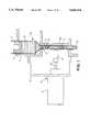
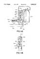
- FIG. 1is a cross-sectional view of the pump cartridge and dispensing actuator mounted on a frame;
- FIG. 2is a perspective view of the pump cartridge reservoir
- FIG. 3is a view from above of the pump cartridge
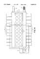
- FIG. 4is a view from above of a plurality of pump cartridges mounted on a first embodiment dispensing assembly including a rectangular frame and chassis of an X-Y axis robot;
- FIG. 5is a perspective view of a dispensing assembly of a second embodiment of the invention.
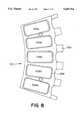
- FIG. 6is a top view of a slide frame for providing five sealed cavities above five different slides holding tissue samples
- FIG. 7is a top view of a slide frame base
- FIG. 8is a top view of a slide frame housing
- FIG. 9is a side cross-sectional view showing the dispensing actuator of the dispensing station and an exemplary cartridge pump being engaged by the dispensing actuator;
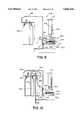
- FIG. 10is a side cross-sectional view of a rinse device housed in the dispensing station
- FIGS. 11a and 11bare side cross-sectional views of a vacuum hose and transport mechanism for removing rinse and reagent from slides contained on the slide rotor;
- FIGS. 12-14are cross-sectional views of the uppermost portion of the cartridge reservoir, demonstrating alternative constructions.
- the cartridge pump CPcomprises a pump cartridge reservoir 1 in the shape of a cylindrical barrel.
- the cartridge reservoir 1has a lower outlet 11 which is directly connected to a metering chamber comprised of a segment of compressible tubing 2, an inlet valve 3, and an outlet valve 4.
- the distance between the inlet valve 3 and the outlet valve 4, and the inner diameter of the tubing 2defines a volume which can be filled with a liquid.
- a nozzle 5is placed below the outlet valve 4 for the purpose of decreasing the flow velocity of the liquid.
- the cartridge reservoircontains a volume of liquid 12 which is sealed from above by a sliding plunger 6.
- the cartridge reservoir 1, inlet valve 3, outlet valve 4, plunger 6, metering chamber 2, and nozzle 5are the components of the cartridge pump CP.
- the cartridge pump CPrests on a rectangular frame 7 which can be made of plastic.
- a single rectangular frame 7can hold a plurality of cartridge pumps CP.
- the rectangular frame 7can be removed from the chassis 8 by simply lifting the frame, thereby lifting all the cartridge pumps with it. In this manner, the wetted components can be easily separated from the electromechanical components.
- the first embodiment dispensing assemblyfurther includes dispensing actuators DA.
- Each dispensing actuator DAcomprises a solenoid 9, arm 22, and rubber hammer 10.
- the arm 22extends forcefully, thereby pressing the rubber hammer 10 against the outer wall of the metering chamber tubing 2. This action deforms the tubing, causing the compressible tubing to assume a compressed shape 2a. Since the total volume inside the metering chamber between the valves 3 and 4 is decreased, a volume of liquid is expelled in the direction defined by the valves 3 and 4. In FIG. 1, the valves are shown as allowing fluid in the downward direction only.
- the fluidSince the diameter of the outlet valve 4 leaflets is comparatively narrow relative to the diameter of the tubing 2, the fluid has a high flow velocity. This results in a forceful squirting of the liquid. This aspect is often undesirable, since it may lead to splattering of the liquid if the object surface of the fluid is situated immediately below. Therefore, the nozzle 5 is placed below the outlet valve 4.
- the nozzlehas an inner diameter greater than the diameter of the outlet valve 4 leaflets. This aspect causes the high velocity fluid to first accumulate in the space above and within the inner aspect of the nozzle. The liquid thus exits the nozzle 5 at a slower velocity, ideally in a dropwise manner.
- the rubber hammer 10is also compressible in order to further decrease the flow velocity of the liquid. Most solenoids tend to extend suddenly and forcefully. This results in a very rapid compression of the tubing 2. In order to decrease this rate of compression, the solenoid arm is fitted with a compressible rubber hammer 10 which absorbs some of the initial force upon impact with the tubing 2.
- the tubing 2can be made of silicone rubber, vinyl, polyurethane, flexible polyvinyl chloride (PVC) or other synthetic or natural resilient elastomers. Such types of tubing are commonly used for peristaltic pumps.
- the valvescan be obtained from Vernay Laboratories, Inc., Yellow Springs, Ohio, 45387 (part #VL 743-102).
- the outer aspect of the pump cartridge reservoir 1has longitudinal ridges 13. These ridges fit into grooves in the frame 7, see FIG. 1, in a lock and key fashion. Different cartridges are manufactured with different patterns of ridges in order to identify the contents. In this manner, any particular cartridge will fit only into a position of the frame with a corresponding pattern of grooves. This feature will prevent the possibility of the operator placing the cartridge in an unintended position of the frame.
- thisshows the variety of possible positions for ridges 13 on the outer surface of the pump cartridge reservoir 1.
- thisshows the first embodiment of the dispensing assembly comprising a rectangular frame 7 having plurality of slots 14 for cartridge pumps in position on the chassis 8 a different dispensing actuator DA being associated with each cartridge pump CP.
- the chassisis mounted on a pair of cylindrical bars 15. In this case one of the bars is threaded and attached to a motor 16.
- a cable drivemay be provided.
- the motorcan be a conventional stepping motor or servo motor and driven by a computer-generated signal through an electronic interface.
- FIG. 5shows a second embodiment 500 of a dispensing assembly in perspective.
- the dispensing assembly 500comprises a substantially circular assembly base 502, a slide rotor 504 rotatable on the assembly base 502, a reagent rotor 506 also rotatable on the assembly base, and a dispensing station 508.
- the slide rotor 504is driven to rotate by a servo motor (not shown) and carries ten slide frames 510 that are radially asserted into and detachable from it.
- a top view of single slide frame 510is shown in FIG. 6.
- the slide frame 510comprises a slide frame base 514 shown in FIG. 7.
- the slide frame baseincludes a plurality of heated areas 516 which underlie each of the slide positions 512a-512e and incorporate resistive heating elements, not shown.
- the heating elementsare integrally formed in the slide frame base 514. Electricity for powering the elements is provided into the slide frame 510 from the assembly base 502 via first and second contacts 518.
- third and fourth contacts 520enable temperature sensing of the heated areas via thermocouples also integrally formed in the slide frame base 514.
- a slide frame housing 522Adapted to overlay the slide frame base is a slide frame housing 522.
- FIG. 8is a top view of the slide frame housing 522 showing essentially a rigid plastic or metal frame 524 with five oval holes 526a-526e corresponding to each of the slide positions 512a-512e.
- a silicon rubber gasket 528is also provided under the plastic frame 524.
- the slide frame housing 522including the gasket 528 and plastic frame 524, is bolted onto the slide frame base 514 by two Allen bolts 530 to provide individual sealed cavities approximately 0.2-0.4 inches deep over each tissue sample slide placed at each of the slide positions 512a-512e.
- a total of 3 ml of reagents and/or rinsescan be placed in contact with the tissue samples of each one of the slides but a maximum quantity of 2 ml is preferable. Since the silicone gasket 528 is compressed by the plastic frame 522 against the slide frame base 514, the cavities over each of the frame positions are mutually sealed from each other.
- the slide rotor 504above the slide rotor 504 is a non-rotating slide cover 532.
- This disk-like structurerides above the slide rotor 504 but does not turn with the slide rotor. Basically, it forms a cover for all of the tissue samples held in each of the slide frames 510 so that evaporation of reagents or rinses contained on the slides can be inhibited and also so that environmental contamination of the tissue samples is prevented.
- reagent rotor 506Positioned above the slide rotor 504 is the reagent rotor 506. This reagent rotor 506 is similarly adapted to rotate on the assembly base 502 and is driven by another servo motor (not shown) so that the reagent rotor 506 and slide rotor 504 can rotate independently from each other.
- the reagent rotor 506is adapted to carry up to ten arcuate cartridge frames 534. These arcuate cartridge frames are detachable from the reagent rotor 506 and can be selectively attached at any one of the ten possible points of connection. Each arcuate cartridge frame 534 is capable of carrying five of the reagent cartridge pumps CP.
- the reagent cartridge pump CPis vertically insertable down into a slot 536 in the arcuate cartridge frame 534 so that the nozzle tip 538 extends down below the cartridge frame and the meter chamber tubing 2 is exposed.
- the arcuate cartridge frame 534 including any cartridge pumps CPis then slidably insertable onto the reagent rotor 506.
- the dispensing station 508comprises a dispensing actuator DA for engaging the meter chamber tubing 2 of any one of the reagent cartridge pumps CP in any slot in any one of the arcuate cartridge frames 534. Further, the dispensing station 508 includes rinse bottles 540 that can supply rinses into any one of the slides on any one of the slide frames 510 via rinse tubes 542, and a rinse removal vacuum 544 including a vacuum tube that is extendable down into any one of the cavities in the slide frames 510 to remove rinse or reagent.
- the dispensing station 508includes a station frame that has a front wall 546 generally following the curvature of the assembly base 502.
- the station framealso includes a horizontal top wall 548 continuous with the front wall 546 and from which rinse bottles 540 are hung.
- the front wall 546 of the station housingsupports a single dispensing actuator DA.
- the dispensing actuator DAincludes a solenoid or linear stepping motor 9, an arm 22, and a compressible rubber hammer 10 as described in connection with the dispensing actuator illustrated in FIG. 1.
- Use of a linear stepping motor instead of a solenoidsomewhat negates the necessity of the rubber hammer being highly compressible since the rate of extension of linear stepping motors can be controlled to a slow speed.
- the reciprocating hammer of the dispensing actuatorcould take the form of a cam, driven by a rotary motor, that engages the compressible tubing so that rotation of the cam will deform the compressible tubing.
- the rubber hammer 10Upon actuation of the solenoid 9, the rubber hammer 10 extends outwardly to engage the compressible tubing 2 of the particular cartridge pump CP that has been rotated into position in front of the dispensing actuator DA on the reagent rotor 504.
- the liquid dispensed from the pump cartridge CP by the action of the dispensing actuator DAfalls down through a hole 550 formed in the slide cover 532 into the particular medical slide that has been brought into position in front of the dispensing actuator DA by the rotation of the slide rotor 504.
- any one of fifty slides, which the slide rotor 504 is capable of carrying,can be accessed and treated with any one of fifty different reagents that the reagent rotor 506 is capable of carrying in the cartridge pumps CP by properly rotating both the reagent rotor and the slide rotor.
- both the reagent cartridge pump CP carrying the desired reagent and the slide which the operator intends to receive this reagentare brought to circumferential position of the dispensing actuator DA.
- the dispensing station 508also carries up to eight different rinses that can be delivered through rinse tubes 542 to any one of the slides held on the slide rotor 504.
- the rinse bottles 540are screwed into a female threaded cap 552 secured to the underside of the horizontal top wall 548 of the station frame. Compressed air is from a compressor 554 is provided into each one of the rinse bottles 540. The pressure above the rinse then enables the rinse to be forced out through the dip tube 556 through rinse hose 558 when a pinch valve 560 is opened.
- a predetermined amount of rinsecan be provided out through the rinse tube 542 into the particular medical slide that has been brought underneath the rinse tube end 562 by the rotation of the slide rotor.
- Eight different rinse tubes 542corresponding to each rinse bottle 540 and each controlled by a separate pinch valve.
- Eight holesare provided in the slide cover 532 underneath the ends of the rinse tubes 542 so that the rinse can reach the slides.
- an extendable vacuum hose 544is also provided on the vertical wall 546 of the station housing.
- the vacuum hose 544is supported by a hose transport mechanism 570 that allows the vacuum hose 544 to be extended down into a cavity of a slide frame 510 to remove any rinse and reagent covering the tissue sample of the slide.
- the suctionis created by a partial vacuum generated in vacuum bottle 572 by a compressor, not shown. Consequently, the rinse and reagent is sucked in through the vacuum hose 544 and into the vacuum bottle when the vacuum hose transport mechanism 570 brings the vacuum hose end in contact with the rinse and/or reagent in cavity of the slide frame 510.
- the vacuum hose transport mechanismcomprises a motor 574.
- a reciprocating link 576is attached to a crank arm 575 so that the rotation of the motor 574 causes the reciprocating link 576 to traverse in a vertical direction.
- a bottom portion of the reciprocating link 576is connected to a lever 578 that is pivotally attached to the station frame.
- the other end of this leveris connected to a vacuum hose clamp 580 that is connected via to pivot arms 582 to a plate 584 rigidly attached to the station frame. The net effect of these connections is that when the motor 574 is rotated, the slide arm 576 descends in the vertical direction.
- the lever 578is pivoted clockwise around its fulcrum causing the hose clamp 580 to pivot up and away on the two pivot arms 582 from the slide as shown in FIG. 11b.
- the motoris automatically turned off as the slide reaches its two extreme ends of movement by the contact of the electrical terminals 584 of the slide to the contact plates 586 connected to the station frame.
- a microprocessorcontrols the entire dispensing assembly 500. That is, an operator programs the microprocessor with the information such as the location of reagents on the reagent rotor and the location of slides on the slide rotor. The operator then programs the particular histochemical protocol to be performed on the tissue samples. Variables in these protocols can include the particular reagent used on the tissue sample, the time that the tissue sample is allowed to react with the reagent, whether the tissue sample is then heated to exposed or develop the tissue sample, the rinse that is then used to deactivate the reagent, followed by the subsequent removal of the rinse and reagent to allow subsequent exposure to a possibly different reagent.
- the dispensing assemblyenables complete random access, i.e. any reagent to any slide in any sequence.
- An important aspect of the above-described inventionis its ability to retain the fluid until such time as the solenoid hammer 10 presses on the metering chamber tubing 2.
- both one-way valves 3 and 4are aligned in the same direction, allowing only downward flow. It was found during construction that using valves with a low opening ("cracking") pressure resulted in the liquid dripping out of the nozzle. There are two solutions to this problem. The most obvious is to use valves with an opening pressure greater than the pressure head of liquid. In this manner, the outlet valve 4 will not allow fluid exit until a certain minimum force is applied which is greater than the pressure head of the standing liquid.
- a second alternative to prevent spontaneous dripping of the liquid out of the outlet valve 4is to use a plunger 6 with an amount of friction against the inner surface of the reservoir 1 greater than the gravity pressure of the liquid 12.
- An additional advantage of the plunger 6is that it prevents spillage of the liquid 12 from the top of the reservoir 1 (which would likely occur if the reservoir were left open from above). In this manner, the plunger will not be drawn downwards inside the reservoir merely by the weight of the liquid. However, when the metering chamber is emptied and a small amount of liquid is drawn from the reservoir 1 to refill the metering chamber, the plunger's friction to the reservoir wall is overcome. The plunger 6 thereby moves downward a distance proportional to the volume of liquid expelled. We have found it useful to apply a thin coat of a lubricant such as petroleum jelly to ensure that the plunger 6 moves smoothly downward within the reservoir.
- valve opening pressure and plunger frictionmay be used to prevent dripping, but given the low opening pressure typically found in valves of the type used, friction greater than gravity pressure of the liquid is preferred.
- FIG. 12shows another alternative construction of the cartridge top.
- a one-way valve 17is placed at the top of the reservoir 1.
- the valve 17has an opening pressure greater than the gravity pressure of the liquid within the reservoir.
- This third valve 17is aligned in the same direction as the metering chamber valves 3 and 4. This allows the entrance of air into the reservoir as liquid is removed. In this case, cracking pressure of any or all of the three valves 3, 4 and 17 prevents spontaneous dripping from the outlet valve. Additionally, the valve 17 prevents spillage of the contents of the reservoir.
- FIG. 13shows another alternative construction for the top of the cartridge.
- a rolling diaphragm cover 18is mounted at the top of the reservoir 1 and is drawn into the reservoir as the liquid is used up. This construction prevents spillage of the liquid 12 as well as provides a seal to prevent air entry.
- the rolling diaphragmcan be made of any thin flexible elastomer such as natural rubber.
- the top of the rolling diaphragmcan be sealed to the reservoir wall i by stretching the diaphragm over the reservoir, with an adhesive or by heat sealing.
- FIG. 14demonstrates a third alternative construction.
- the top of the reservoiris closed, except for a small aperture 19 for the entrance of air.
- the diameter of the aperture at the top of the reservoircan be sufficiently small to effectively prevent accidental spillage of the liquid contents of the cartridge but still allow air entry as liquid is dispensed from the cartridge.
- a fluid level sensormay be provided adjacent to the cartridge reservoir.
- a shaftcan be connected to the top of the plunger.
- the shaftcan be designed with a shape such that as it is drawn into the cartridge reservoir, it can optically or electrically open or close a circuit at a certain depth within the cartridge reservoir. In this manner, the shaft connected to the plunger can signal to a computer the depth of entry into the cartridge reservoir. The depth of entry would therefore be directly proportional to the amount of liquid remaining in the cartridge reservoir.
- Such an arrangementprovides an automatic means for sensing the amount of liquid remaining inside the reservoir.
- a variety of different configurations for the dispensing actuators DAmay be used to apply pressure on the metering chamber tubing.
- a push-type of actuator DAis shown in FIG. 1, a rotary or pull-type could also be used with slight modifications to the design, as would be obvious so as to apply a pressure on the metering chamber tubing.
- a solenoid valvecould also be used to control pressure to a pneumatic cylinder whose piston rod is the actuator.
- a piezoelectric transducermay apply the pressure to the metering chamber tubing.
- the pumpis operable with the metering chamber positioned above the reservoir.
- Disclosure Document No. 252981 filed May 10, 1990 at the U.S. Patent and Trademark Officeshows details of a potential system embodying the present invention.
Landscapes
- Engineering & Computer Science (AREA)
- Mechanical Engineering (AREA)
- General Engineering & Computer Science (AREA)
- Chemical & Material Sciences (AREA)
- Health & Medical Sciences (AREA)
- Analytical Chemistry (AREA)
- Biochemistry (AREA)
- Life Sciences & Earth Sciences (AREA)
- Physics & Mathematics (AREA)
- General Health & Medical Sciences (AREA)
- General Physics & Mathematics (AREA)
- Immunology (AREA)
- Pathology (AREA)
- Clinical Laboratory Science (AREA)
- Chemical Kinetics & Catalysis (AREA)
- Sampling And Sample Adjustment (AREA)
Abstract
Description
Claims (19)
Priority Applications (7)
| Application Number | Priority Date | Filing Date | Title |
|---|---|---|---|
| US08/251,597US5645114A (en) | 1992-05-11 | 1994-05-31 | Dispensing assembly with interchangeable cartridge pumps |
| US08/887,178US5947167A (en) | 1992-05-11 | 1997-07-02 | Dispensing assembly with interchangeable cartridge pumps |
| US09/020,983US6092695A (en) | 1992-05-11 | 1998-02-10 | Interchangeable liquid dispensing cartridge pump |
| US09/205,945US6180061B1 (en) | 1992-05-11 | 1998-12-04 | Moving platform slide stainer with heating elements |
| US09/610,242US6244474B1 (en) | 1992-05-11 | 2000-07-06 | Interchangeable liquid dispensing cartridge pump |
| US09/702,298US7718435B1 (en) | 1992-05-11 | 2000-10-31 | Automated slide stainer with slide housing |
| US10/823,368US20040191128A1 (en) | 1992-05-11 | 2004-04-12 | Slide stainer with heating |
Applications Claiming Priority (2)
| Application Number | Priority Date | Filing Date | Title |
|---|---|---|---|
| US07/881,397US5316452A (en) | 1992-05-11 | 1992-05-11 | Dispensing assembly with interchangeable cartridge pumps |
| US08/251,597US5645114A (en) | 1992-05-11 | 1994-05-31 | Dispensing assembly with interchangeable cartridge pumps |
Related Parent Applications (1)
| Application Number | Title | Priority Date | Filing Date |
|---|---|---|---|
| US07/881,397Continuation-In-PartUS5316452A (en) | 1992-05-11 | 1992-05-11 | Dispensing assembly with interchangeable cartridge pumps |
Related Child Applications (1)
| Application Number | Title | Priority Date | Filing Date |
|---|---|---|---|
| US08/887,178Continuation-In-PartUS5947167A (en) | 1992-05-11 | 1997-07-02 | Dispensing assembly with interchangeable cartridge pumps |
Publications (1)
| Publication Number | Publication Date |
|---|---|
| US5645114Atrue US5645114A (en) | 1997-07-08 |
Family
ID=26941709
Family Applications (1)
| Application Number | Title | Priority Date | Filing Date |
|---|---|---|---|
| US08/251,597Expired - LifetimeUS5645114A (en) | 1992-05-11 | 1994-05-31 | Dispensing assembly with interchangeable cartridge pumps |
Country Status (1)
| Country | Link |
|---|---|
| US (1) | US5645114A (en) |
Cited By (79)
| Publication number | Priority date | Publication date | Assignee | Title |
|---|---|---|---|---|
| US5947167A (en)* | 1992-05-11 | 1999-09-07 | Cytologix Corporation | Dispensing assembly with interchangeable cartridge pumps |
| US6092695A (en)* | 1992-05-11 | 2000-07-25 | Cytologix Corporation | Interchangeable liquid dispensing cartridge pump |
| US6096271A (en)* | 1998-02-27 | 2000-08-01 | Cytologix Corporation | Random access slide stainer with liquid waste segregation |
| US6105636A (en)* | 1998-03-26 | 2000-08-22 | Technorama S.R.L. | Apparatus for the controlled withdrawal and delivery of volumetrically metered liquids |
| US6119440A (en)* | 1998-10-02 | 2000-09-19 | R. A. Jones & Co. Inc. | Single level multiple product filler wheel |
| US6180061B1 (en) | 1992-05-11 | 2001-01-30 | Cytologix Corporation | Moving platform slide stainer with heating elements |
| US6183693B1 (en) | 1998-02-27 | 2001-02-06 | Cytologix Corporation | Random access slide stainer with independent slide heating regulation |
| US20010000723A1 (en)* | 1998-06-16 | 2001-05-03 | Mcluen Gary R. | Multi-well rotary synthesizer |
| US6271042B1 (en) | 1998-08-26 | 2001-08-07 | Alpha Innotech Corporation | Biochip detection system |
| US6296809B1 (en) | 1998-02-27 | 2001-10-02 | Ventana Medical Systems, Inc. | Automated molecular pathology apparatus having independent slide heaters |
| US6352861B1 (en)* | 1990-03-02 | 2002-03-05 | Ventana Medical Systems, Inc. | Automated biological reaction apparatus |
| US6354345B1 (en)* | 1990-02-02 | 2002-03-12 | Isco, Inc. | Pumping system |
| US6465207B1 (en) | 2000-11-03 | 2002-10-15 | Cytologix Corporation | Silver-based staining processes employing non-gelling gelatin |
| US6472217B1 (en)* | 1990-03-02 | 2002-10-29 | Ventana Medical Systems, Inc. | Slide aqueous volume controlling apparatus |
| US20030017075A1 (en)* | 1999-07-08 | 2003-01-23 | Lee Angros | In situ heat induced antigen recovery and staining method |
| US6544798B1 (en) | 1999-02-26 | 2003-04-08 | Ventana Medical Systems, Inc. | Removal of embedding media from biological samples and cell conditioning on automated staining instruments |
| US6582962B1 (en) | 1998-02-27 | 2003-06-24 | Ventana Medical Systems, Inc. | Automated molecular pathology apparatus having independent slide heaters |
| US20030136666A1 (en)* | 2002-01-18 | 2003-07-24 | Heiner Ophardt | Combination liquid dispenser and electrochemical cell |
| US6656428B1 (en) | 1999-08-06 | 2003-12-02 | Thermo Biostar, Inc. | Automated point of care detection system including complete sample processing capabilities |
| US6673620B1 (en)* | 1999-04-20 | 2004-01-06 | Cytologix Corporation | Fluid exchange in a chamber on a microscope slide |
| US20040121485A1 (en)* | 1998-09-03 | 2004-06-24 | Keri Hopkins | Removal of embedding media from biological samples and cell conditioning on automated staining instruments |
| US20040191128A1 (en)* | 1992-05-11 | 2004-09-30 | Cytologix Corporation | Slide stainer with heating |
| US6828154B1 (en) | 2000-11-03 | 2004-12-07 | Cytologix Corporation | Staining method with chromic acid precursors |
| US6855552B2 (en) | 1998-09-03 | 2005-02-15 | Ventana Medical Systems | Automated immunohistochemical and in situ hybridization assay formulations |
| US6855559B1 (en) | 1998-09-03 | 2005-02-15 | Ventana Medical Systems, Inc. | Removal of embedding media from biological samples and cell conditioning on automated staining instruments |
| US20050035156A1 (en)* | 2003-08-11 | 2005-02-17 | Michael Hersch | Fluid dispensing apparatus |
| US20050042768A1 (en)* | 2003-08-19 | 2005-02-24 | Fredrick Joseph P. | Apparatus for substrate handling |
| US20060147351A1 (en)* | 2003-06-09 | 2006-07-06 | Dako Denmark A/S | Diaphram metering chamber dispensing systems |
| US20060252025A1 (en)* | 2004-12-30 | 2006-11-09 | Ventana Medical Systems, Inc. | Low temperature deparaffinization |
| US20060275889A1 (en)* | 1999-07-08 | 2006-12-07 | Lee Angros | In situ heat induced antigen recovery and staining apparatus and method |
| US20060275861A1 (en)* | 1999-07-08 | 2006-12-07 | Lee Angros | In situ heat induced antigen recovery and staining apparatus and method |
| US20060281116A1 (en)* | 1999-07-08 | 2006-12-14 | Lee Angros | In situ heat induced antigen recovery and staining apparatus and method |
| US20070092431A1 (en)* | 2005-06-28 | 2007-04-26 | Resasco Daniel E | Methods for growing and harvesting carbon nanotubes |
| US7270785B1 (en) | 2001-11-02 | 2007-09-18 | Ventana Medical Systems, Inc. | Automated molecular pathology apparatus having fixed slide platforms |
| US7303725B2 (en) | 2002-04-15 | 2007-12-04 | Ventana Medical Systems, Inc. | Automated high volume slide staining system |
| US20070289658A1 (en)* | 2006-06-13 | 2007-12-20 | Trw Vehicle Safety System Inc. | Method of filling containers with gases |
| US7378055B2 (en) | 2002-04-26 | 2008-05-27 | Ventana Medical Systems, Inc. | Automated molecular pathology apparatus having fixed slide platforms |
| US7396512B2 (en) | 2003-11-04 | 2008-07-08 | Drummond Scientific Company | Automatic precision non-contact open-loop fluid dispensing |
| US7396508B1 (en)* | 2000-07-12 | 2008-07-08 | Ventana Medical Systems, Inc. | Automated molecular pathology apparatus having independent slide heaters |
| US7400983B2 (en) | 2002-12-20 | 2008-07-15 | Dako Denmark A/S | Information notification sample processing system and methods of biological slide processing |
| US20080194034A1 (en)* | 2005-04-21 | 2008-08-14 | Celerus Diagnostics, Inc. | Method And Apparatus For Automated Rapid Immunohistochemistry |
| US7468161B2 (en) | 2002-04-15 | 2008-12-23 | Ventana Medical Systems, Inc. | Automated high volume slide processing system |
| US20080318129A1 (en)* | 2005-01-25 | 2008-12-25 | Gene Lewis | Fuel Cell Cathodes |
| US7550298B2 (en) | 1998-09-03 | 2009-06-23 | Ventana Medical Systems, Inc. | Automated immunohistochemical and in situ hybridization assay formulations |
| US20100015009A1 (en)* | 2006-04-13 | 2010-01-21 | Imi Vision Limited | Fluid dispenser |
| US20100028978A1 (en)* | 2005-05-24 | 2010-02-04 | Angros Lee H | In situ heat induced antigen recovery and staining apparatus and method |
| US7744817B2 (en) | 2003-08-11 | 2010-06-29 | Sakura Finetek U.S.A., Inc. | Manifold assembly |
| US20100167943A1 (en)* | 2008-06-09 | 2010-07-01 | Nils Adey | System and Method for Hybridization Slide Processing |
| US7767152B2 (en) | 2003-08-11 | 2010-08-03 | Sakura Finetek U.S.A., Inc. | Reagent container and slide reaction retaining tray, and method of operation |
| US20100200021A1 (en)* | 2006-02-17 | 2010-08-12 | Nils Adey | Slide Conditioning Systems and Methods |
| US20110150725A1 (en)* | 2005-05-24 | 2011-06-23 | Lee Angros | In situ heat induced antigen recovery and staining apparatus and method |
| US20110190153A1 (en)* | 2008-06-09 | 2011-08-04 | Nils Adey | System and method for hybridization slide processing |
| US8220156B2 (en) | 2010-10-28 | 2012-07-17 | The Gillette Company | Liquid dispensing hair removal kit |
| WO2012162101A1 (en)* | 2011-05-20 | 2012-11-29 | Geneforge, Inc. | Drop-in nozzle |
| US8393166B2 (en)* | 2006-05-09 | 2013-03-12 | Teledyne Instruments, Inc. | Sample collector and components thereof |
| US8459509B2 (en) | 2006-05-25 | 2013-06-11 | Sakura Finetek U.S.A., Inc. | Fluid dispensing apparatus |
| JP2013525818A (en)* | 2010-05-06 | 2013-06-20 | プレシジョン バイオシステムズ,エルエルシー | Fluid supply system and apparatus for performing fluid supply |
| US8501434B2 (en) | 2010-10-06 | 2013-08-06 | Biocare, LLC | Method for processing non-liquid biological samples with dynamic application of a processing liquid |
| US8510957B2 (en) | 2010-10-28 | 2013-08-20 | The Gillette Company | Applicator with a baffle for a hair removal device |
| US8580568B2 (en) | 2011-09-21 | 2013-11-12 | Sakura Finetek U.S.A., Inc. | Traceability for automated staining system |
| US8752732B2 (en) | 2011-02-01 | 2014-06-17 | Sakura Finetek U.S.A., Inc. | Fluid dispensing system |
| US8782904B2 (en) | 2010-10-28 | 2014-07-22 | The Gillette Company | Applicator for liquid dispensing hair removal device |
| US8793879B2 (en) | 2010-10-28 | 2014-08-05 | The Gillette Company | Cartridge biasing applicator for a hair removal device |
| US8832942B2 (en) | 2010-10-28 | 2014-09-16 | The Gillette Company | Hair removal device with cartridge retention cover |
| US20140299626A1 (en)* | 2011-02-03 | 2014-10-09 | Cps Color Equipment Spa Con Unicon Socio | Apparatus for the delivery of fluid products |
| US8932543B2 (en) | 2011-09-21 | 2015-01-13 | Sakura Finetek U.S.A., Inc. | Automated staining system and reaction chamber |
| US20150093834A1 (en)* | 2012-12-13 | 2015-04-02 | Roche Molecular Systems, Inc. | Supply module for an automated analyzer |
| US9069358B2 (en) | 2013-06-24 | 2015-06-30 | Biolytic Lab Performance, Inc. | System for controlling and optimizing reactions in solid phase synthesis of small molecules |
| US9156175B2 (en) | 2011-12-09 | 2015-10-13 | The Gillette Company | Fluid applicator for a personal-care appliance |
| US20150360227A1 (en)* | 2014-06-17 | 2015-12-17 | Life Technologies Corporation | Pinch Flow Regulator |
| US9518899B2 (en) | 2003-08-11 | 2016-12-13 | Sakura Finetek U.S.A., Inc. | Automated reagent dispensing system and method of operation |
| US9789620B2 (en) | 2010-10-28 | 2017-10-17 | The Gillette Company | Pump for a liquid dispensing hair removal device |
| US20180071740A1 (en)* | 2015-05-29 | 2018-03-15 | Roche Diagnostics Operations, Inc. | Cartridge for dispensing particles and a reagent fluid |
| US9945763B1 (en) | 2011-02-18 | 2018-04-17 | Biocare Medical, Llc | Methods and systems for immunohistochemistry heat retrieval of biological samples |
| US10184862B2 (en) | 2008-11-12 | 2019-01-22 | Ventana Medical Systems, Inc. | Methods and apparatuses for heating slides carrying specimens |
| EP3593145A4 (en)* | 2017-07-18 | 2020-05-13 | Hewlett-Packard Development Company, L.P. | Swapable reagent modules |
| US10794805B2 (en) | 2013-12-13 | 2020-10-06 | Ventana Medical Systems, Inc. | Automated histological processing of biological specimens and associated technology |
| US11249095B2 (en) | 2002-04-15 | 2022-02-15 | Ventana Medical Systems, Inc. | Automated high volume slide processing system |
| US11619218B2 (en)* | 2017-06-19 | 2023-04-04 | Idee & Prodotti S.R.L. | Positive displacement pump |
Citations (23)
| Publication number | Priority date | Publication date | Assignee | Title |
|---|---|---|---|---|
| US3768704A (en)* | 1971-10-26 | 1973-10-30 | Tech Sa D Et | Fluid dispenser |
| US4095722A (en)* | 1976-03-18 | 1978-06-20 | Miller Kenneth L | Dripless dispenser and method of dispensing a flowable material |
| US4130224A (en)* | 1976-10-08 | 1978-12-19 | Envair, Inc. | Viscous liquid dispenser |
| US4224032A (en)* | 1976-12-17 | 1980-09-23 | Eastman Kodak Company | Method and apparatus for chemical analysis |
| US4268226A (en)* | 1977-08-06 | 1981-05-19 | Dunlop Limited | Tube type pump and wave motor |
| US4334640A (en)* | 1977-08-08 | 1982-06-15 | Douwe Egberts Koninklijke Tabaksfabriek-Koffiebranderijen-Theehandel B.V. | Exchangeable concentrate container for beverage dispensing machines |
| US4537561A (en)* | 1983-02-24 | 1985-08-27 | Medical Technology, Ltd. | Peristaltic infusion pump and disposable cassette for use therewith |
| US4741259A (en)* | 1986-04-29 | 1988-05-03 | U.S. Philips Corporation | Coffee maker having a detachable cassette containing the pump and heater assembly |
| US4764342A (en)* | 1985-02-27 | 1988-08-16 | Fisher Scientific Company | Reagent handling |
| US4798580A (en)* | 1987-04-27 | 1989-01-17 | Site Microsurgical Systems, Inc. | Disposable peristaltic pump cassette system |
| US4824337A (en)* | 1987-12-24 | 1989-04-25 | The Gorman-Rupp Company | Valve assembly for an oscillating pump |
| US4838887A (en)* | 1987-12-15 | 1989-06-13 | Shiley Infusaid Inc. | Programmable valve pump |
| US4846797A (en)* | 1985-05-14 | 1989-07-11 | Intelligent Medicine, Inc. | Syringe positioning device for enhancing fluid flow control |
| US4847208A (en)* | 1987-07-29 | 1989-07-11 | Bogen Steven A | Apparatus for immunohistochemical staining and method of rinsing a plurality of slides |
| US4846636A (en)* | 1986-09-02 | 1989-07-11 | Critikon, Inc. | Parenteral solution pump assembly |
| US4967940A (en)* | 1989-02-21 | 1990-11-06 | Minnesota Mining And Manufacturing Co. | Method and apparatus for precision squeeze tube valving, pumping and dispensing of work fluid(s) |
| US4974754A (en)* | 1987-11-30 | 1990-12-04 | Alphasem Ag | Metering apparatus for metering and delivering fluid or pasty substances and use of said metering apparatus |
| US4974952A (en)* | 1988-03-31 | 1990-12-04 | Focht Daniel C | Live cell chamber for microscopes |
| US5049359A (en)* | 1985-02-28 | 1991-09-17 | Konishiroku Photo Industry Co., Ltd. | Apparatus for biochemical analysis |
| US5100030A (en)* | 1990-05-24 | 1992-03-31 | Inopak Ltd. | Fixtures for fluid dispensing bags |
| US5232664A (en)* | 1991-09-18 | 1993-08-03 | Ventana Medical Systems, Inc. | Liquid dispenser |
| US5273905A (en)* | 1991-02-22 | 1993-12-28 | Amoco Corporation | Processing of slide mounted material |
| US5425918A (en)* | 1990-07-18 | 1995-06-20 | Australian Biomedical Corporation | Apparatus for automatic tissue staining for immunohistochemistry |
- 1994
- 1994-05-31USUS08/251,597patent/US5645114A/ennot_activeExpired - Lifetime
Patent Citations (24)
| Publication number | Priority date | Publication date | Assignee | Title |
|---|---|---|---|---|
| US3768704A (en)* | 1971-10-26 | 1973-10-30 | Tech Sa D Et | Fluid dispenser |
| US4095722A (en)* | 1976-03-18 | 1978-06-20 | Miller Kenneth L | Dripless dispenser and method of dispensing a flowable material |
| US4130224A (en)* | 1976-10-08 | 1978-12-19 | Envair, Inc. | Viscous liquid dispenser |
| US4224032A (en)* | 1976-12-17 | 1980-09-23 | Eastman Kodak Company | Method and apparatus for chemical analysis |
| US4268226A (en)* | 1977-08-06 | 1981-05-19 | Dunlop Limited | Tube type pump and wave motor |
| US4334640A (en)* | 1977-08-08 | 1982-06-15 | Douwe Egberts Koninklijke Tabaksfabriek-Koffiebranderijen-Theehandel B.V. | Exchangeable concentrate container for beverage dispensing machines |
| US4537561A (en)* | 1983-02-24 | 1985-08-27 | Medical Technology, Ltd. | Peristaltic infusion pump and disposable cassette for use therewith |
| US4764342A (en)* | 1985-02-27 | 1988-08-16 | Fisher Scientific Company | Reagent handling |
| US5049359A (en)* | 1985-02-28 | 1991-09-17 | Konishiroku Photo Industry Co., Ltd. | Apparatus for biochemical analysis |
| US4846797A (en)* | 1985-05-14 | 1989-07-11 | Intelligent Medicine, Inc. | Syringe positioning device for enhancing fluid flow control |
| US4741259A (en)* | 1986-04-29 | 1988-05-03 | U.S. Philips Corporation | Coffee maker having a detachable cassette containing the pump and heater assembly |
| US4846636A (en)* | 1986-09-02 | 1989-07-11 | Critikon, Inc. | Parenteral solution pump assembly |
| US4798580A (en)* | 1987-04-27 | 1989-01-17 | Site Microsurgical Systems, Inc. | Disposable peristaltic pump cassette system |
| US4847208A (en)* | 1987-07-29 | 1989-07-11 | Bogen Steven A | Apparatus for immunohistochemical staining and method of rinsing a plurality of slides |
| US5073504A (en)* | 1987-07-29 | 1991-12-17 | Bogen Steven A | Apparatus and method for immunohistochemical staining |
| US4974754A (en)* | 1987-11-30 | 1990-12-04 | Alphasem Ag | Metering apparatus for metering and delivering fluid or pasty substances and use of said metering apparatus |
| US4838887A (en)* | 1987-12-15 | 1989-06-13 | Shiley Infusaid Inc. | Programmable valve pump |
| US4824337A (en)* | 1987-12-24 | 1989-04-25 | The Gorman-Rupp Company | Valve assembly for an oscillating pump |
| US4974952A (en)* | 1988-03-31 | 1990-12-04 | Focht Daniel C | Live cell chamber for microscopes |
| US4967940A (en)* | 1989-02-21 | 1990-11-06 | Minnesota Mining And Manufacturing Co. | Method and apparatus for precision squeeze tube valving, pumping and dispensing of work fluid(s) |
| US5100030A (en)* | 1990-05-24 | 1992-03-31 | Inopak Ltd. | Fixtures for fluid dispensing bags |
| US5425918A (en)* | 1990-07-18 | 1995-06-20 | Australian Biomedical Corporation | Apparatus for automatic tissue staining for immunohistochemistry |
| US5273905A (en)* | 1991-02-22 | 1993-12-28 | Amoco Corporation | Processing of slide mounted material |
| US5232664A (en)* | 1991-09-18 | 1993-08-03 | Ventana Medical Systems, Inc. | Liquid dispenser |
Cited By (227)
| Publication number | Priority date | Publication date | Assignee | Title |
|---|---|---|---|---|
| US6354345B1 (en)* | 1990-02-02 | 2002-03-12 | Isco, Inc. | Pumping system |
| US20050153453A1 (en)* | 1990-03-02 | 2005-07-14 | Ventana Medical Systems, Inc. | Automated biological reaction apparatus |
| US6943029B2 (en) | 1990-03-02 | 2005-09-13 | Ventana Medical Systems, Inc. | Automated biological reaction apparatus |
| US6827901B2 (en) | 1990-03-02 | 2004-12-07 | Ventana Medical Systems, Inc. | Automated biological reaction apparatus |
| US20030022391A1 (en)* | 1990-03-02 | 2003-01-30 | Ventana Medical Systems, Inc. | Slide aqueous volume controlling apparatus |
| US6352861B1 (en)* | 1990-03-02 | 2002-03-05 | Ventana Medical Systems, Inc. | Automated biological reaction apparatus |
| US6472217B1 (en)* | 1990-03-02 | 2002-10-29 | Ventana Medical Systems, Inc. | Slide aqueous volume controlling apparatus |
| US7220589B2 (en) | 1990-03-02 | 2007-05-22 | Ventana Medical Systems, Inc. | Slide acqueous volume controlling apparatus |
| US7470541B2 (en) | 1990-03-02 | 2008-12-30 | Ventana Medical System, Inc. | Automated biological reaction apparatus |
| US6092695A (en)* | 1992-05-11 | 2000-07-25 | Cytologix Corporation | Interchangeable liquid dispensing cartridge pump |
| US5947167A (en)* | 1992-05-11 | 1999-09-07 | Cytologix Corporation | Dispensing assembly with interchangeable cartridge pumps |
| US7718435B1 (en) | 1992-05-11 | 2010-05-18 | Dako Denmark A/S | Automated slide stainer with slide housing |
| US6244474B1 (en) | 1992-05-11 | 2001-06-12 | Cytologix Corporation | Interchangeable liquid dispensing cartridge pump |
| US20040191128A1 (en)* | 1992-05-11 | 2004-09-30 | Cytologix Corporation | Slide stainer with heating |
| US6180061B1 (en) | 1992-05-11 | 2001-01-30 | Cytologix Corporation | Moving platform slide stainer with heating elements |
| US6183693B1 (en) | 1998-02-27 | 2001-02-06 | Cytologix Corporation | Random access slide stainer with independent slide heating regulation |
| US7217392B2 (en) | 1998-02-27 | 2007-05-15 | Cytologix Corporation | Random access slide stainer with independent slide heating regulation |
| US20070281364A1 (en)* | 1998-02-27 | 2007-12-06 | Bogen Steven A | Random access slide stainer with independent slide heating regulation |
| US20020054830A1 (en)* | 1998-02-27 | 2002-05-09 | Cytologix Corporation | Random access slide stainer with independent slide heating regulation |
| US6096271A (en)* | 1998-02-27 | 2000-08-01 | Cytologix Corporation | Random access slide stainer with liquid waste segregation |
| EP1600759A3 (en)* | 1998-02-27 | 2006-01-11 | Cytologix Corporation | Random access slide stainer with independent slide heating regulation |
| US20040052685A1 (en)* | 1998-02-27 | 2004-03-18 | Ventana Medical Systems, Inc. | Automated molecular pathology apparatus having independent slide heaters |
| EP2278297A1 (en)* | 1998-02-27 | 2011-01-26 | Dako Denmark A/S | Random access slide stainer with independent slide heating regulation |
| CN100403008C (en)* | 1998-02-27 | 2008-07-16 | 文塔纳医疗系统公司 | Automated molecular pathology apparatus having independent slide heaters |
| US6541261B1 (en) | 1998-02-27 | 2003-04-01 | Cytologix Corporation | Method using a slide stainer with independent slide heating regulation |
| US7553672B2 (en) | 1998-02-27 | 2009-06-30 | Dako Denmark A/S | Random access slide stainer with independent slide heating regulation |
| US6582962B1 (en) | 1998-02-27 | 2003-06-24 | Ventana Medical Systems, Inc. | Automated molecular pathology apparatus having independent slide heaters |
| US6783733B2 (en) | 1998-02-27 | 2004-08-31 | Cytologix Corporation | Random access slide stainer with independent slide heating regulation |
| US6296809B1 (en) | 1998-02-27 | 2001-10-02 | Ventana Medical Systems, Inc. | Automated molecular pathology apparatus having independent slide heaters |
| EP1073892A4 (en)* | 1998-02-27 | 2005-10-12 | Ventana Med Syst Inc | Automated molecular pathology apparatus having independent slide heaters |
| US6105636A (en)* | 1998-03-26 | 2000-08-22 | Technorama S.R.L. | Apparatus for the controlled withdrawal and delivery of volumetrically metered liquids |
| US20010051114A1 (en)* | 1998-06-16 | 2001-12-13 | Mcluen Gary R. | Multi-well rotary synthesizer |
| US8747780B2 (en) | 1998-06-16 | 2014-06-10 | Mcluen Design, Inc. | Multi-well rotary synthesizer |
| US7192558B2 (en) | 1998-06-16 | 2007-03-20 | Mcluen Design, Inc. | Multi-well rotary synthesizer |
| US20010000723A1 (en)* | 1998-06-16 | 2001-05-03 | Mcluen Gary R. | Multi-well rotary synthesizer |
| US20010001035A1 (en)* | 1998-06-16 | 2001-05-10 | Northwest Engineering Inc. | Multi-well rotary synthesizer |
| US6811755B2 (en) | 1998-06-16 | 2004-11-02 | Mcluen Design, Inc. | Multi-well rotary synthesizer |
| US8158085B2 (en) | 1998-06-16 | 2012-04-17 | Mcluen Design, Inc. | Multi-well rotary synthesizer |
| US8404196B2 (en) | 1998-06-16 | 2013-03-26 | Mcluen Design, Inc. | Multi-well rotary synthesizer |
| US20010007644A1 (en)* | 1998-06-16 | 2001-07-12 | Mcluen Gary R. | Multi-well rotary synthesizer |
| US6270730B1 (en) | 1998-06-16 | 2001-08-07 | Northwest Engineering Inc. | Multi-well rotary synthesizer |
| US7150998B2 (en) | 1998-06-16 | 2006-12-19 | Mcluen Design, Inc. | Multi-well rotary synthesizer |
| US8147776B2 (en) | 1998-06-16 | 2012-04-03 | Mcluen Design, Inc. | Multi-well rotary synthesizer |
| US20010031502A1 (en)* | 1998-08-26 | 2001-10-18 | Watson Robert Malcolm | Biochip detection system |
| US6271042B1 (en) | 1998-08-26 | 2001-08-07 | Alpha Innotech Corporation | Biochip detection system |
| US6855552B2 (en) | 1998-09-03 | 2005-02-15 | Ventana Medical Systems | Automated immunohistochemical and in situ hybridization assay formulations |
| US7410753B2 (en) | 1998-09-03 | 2008-08-12 | Ventana Medical Systems, Inc. | Removal of embedding media from biological samples and cell conditioning on automated staining instruments |
| US6855559B1 (en) | 1998-09-03 | 2005-02-15 | Ventana Medical Systems, Inc. | Removal of embedding media from biological samples and cell conditioning on automated staining instruments |
| US7550298B2 (en) | 1998-09-03 | 2009-06-23 | Ventana Medical Systems, Inc. | Automated immunohistochemical and in situ hybridization assay formulations |
| US20040121485A1 (en)* | 1998-09-03 | 2004-06-24 | Keri Hopkins | Removal of embedding media from biological samples and cell conditioning on automated staining instruments |
| US6119440A (en)* | 1998-10-02 | 2000-09-19 | R. A. Jones & Co. Inc. | Single level multiple product filler wheel |
| US6544798B1 (en) | 1999-02-26 | 2003-04-08 | Ventana Medical Systems, Inc. | Removal of embedding media from biological samples and cell conditioning on automated staining instruments |
| US20080056954A1 (en)* | 1999-04-20 | 2008-03-06 | Loeffler Herbert H | Fluid exchange in a chamber on a microscope slide |
| US7318913B2 (en) | 1999-04-20 | 2008-01-15 | Cytologix Corporation | Fluid exchange in a chamber on a microscope slide |
| US20040086428A1 (en)* | 1999-04-20 | 2004-05-06 | Cytologix Corporation | Fluid exchange in a chamber on a microscope slide |
| US8173068B2 (en) | 1999-04-20 | 2012-05-08 | Dako Denmark A/S | Fluid exchange in a chamber on a microscope slide |
| US6673620B1 (en)* | 1999-04-20 | 2004-01-06 | Cytologix Corporation | Fluid exchange in a chamber on a microscope slide |
| US20030170144A1 (en)* | 1999-07-08 | 2003-09-11 | Lee Angros | In situ heat induced antigen recovery and staining apparatus and method |
| US8313694B2 (en) | 1999-07-08 | 2012-11-20 | Lee Angros | In situ heat induced antigen recovery and staining apparatus and method |
| US20060275861A1 (en)* | 1999-07-08 | 2006-12-07 | Lee Angros | In situ heat induced antigen recovery and staining apparatus and method |
| US10281375B2 (en) | 1999-07-08 | 2019-05-07 | Lee H. Angros | In situ heat induced antigen recovery and staining method |
| US20060275889A1 (en)* | 1999-07-08 | 2006-12-07 | Lee Angros | In situ heat induced antigen recovery and staining apparatus and method |
| US8007720B2 (en) | 1999-07-08 | 2011-08-30 | Lee Angros | In situ heat induced antigen recovery and staining apparatus and method |
| US7250301B2 (en) | 1999-07-08 | 2007-07-31 | Lee Angros | In situ heat induced antigen recovery and staining method |
| US8052927B2 (en) | 1999-07-08 | 2011-11-08 | Lee Angros | In situ heat induced antigen recovery and staining method |
| US20070231889A1 (en)* | 1999-07-08 | 2007-10-04 | Lee Angros | In situ heat induced antigen recovery and staining method |
| US7951612B2 (en) | 1999-07-08 | 2011-05-31 | Lee H. Angros | In situ heat induced antigen recovery and staining apparatus and method |
| US10416052B2 (en) | 1999-07-08 | 2019-09-17 | Lee H. Angros | In situ heat induced antigen recovery and staining apparatus and method |
| US9976941B2 (en) | 1999-07-08 | 2018-05-22 | Lee H. Angros | In situ heat induced antigen recovery and staining method |
| US8071023B2 (en) | 1999-07-08 | 2011-12-06 | Lee Angros | In situ heat induced antigen recovery and staining apparatus and method |
| US7897106B2 (en) | 1999-07-08 | 2011-03-01 | Lee Angros | Situ heat induced antigen recovery and staining apparatus and method |
| US20030017075A1 (en)* | 1999-07-08 | 2003-01-23 | Lee Angros | In situ heat induced antigen recovery and staining method |
| US9772266B2 (en) | 1999-07-08 | 2017-09-26 | Lee H. Angros | In situ heat induced antigen recovery and staining method |
| US8092742B2 (en) | 1999-07-08 | 2012-01-10 | Lee Angros | In situ heat induced antigen recovery and staining apparatus and method |
| US9606034B2 (en) | 1999-07-08 | 2017-03-28 | Lee H. Angros | In situ heat induced antigen recovery and staining method |
| US20050054080A1 (en)* | 1999-07-08 | 2005-03-10 | Lee Angros | In situ heat induced antigen recovery and staining apparatus and method |
| US6534008B1 (en) | 1999-07-08 | 2003-03-18 | Lee Angros | In situ heat induced antigen recovery and staining apparatus and method |
| US20050053526A1 (en)* | 1999-07-08 | 2005-03-10 | Lee Angros | In situ heat induced antigen recovery and staining apparatus and method |
| US8007721B2 (en) | 1999-07-08 | 2011-08-30 | Lee Angros | In Situ heat induced antigen recovery and staining apparatus and method |
| US9464974B2 (en) | 1999-07-08 | 2016-10-11 | Lee H. Angros | In situ heat induced antigen recovery and staining apparatus and method |
| US9176033B2 (en) | 1999-07-08 | 2015-11-03 | Lee H. Angros | In situ heat induced antigen recovery and staining method |
| US8298485B2 (en) | 1999-07-08 | 2012-10-30 | Lee H. Angros | In situ heat induced antigen recovery and staining apparatus and method |
| US20050054079A1 (en)* | 1999-07-08 | 2005-03-10 | Lee Angros | In situ heat induced antigen recovery and staining apparatus and method |
| US20060281116A1 (en)* | 1999-07-08 | 2006-12-14 | Lee Angros | In situ heat induced antigen recovery and staining apparatus and method |
| US8696988B2 (en) | 1999-07-08 | 2014-04-15 | Lee H. Angros | In situ heat induced antigen recovery and staining apparatus and method |
| US7476362B2 (en) | 1999-07-08 | 2009-01-13 | Lee Angros | In situ heat induced antigen recovery and staining apparatus and method |
| EP1208378B1 (en)* | 1999-07-08 | 2014-03-05 | Lee H. Angros | Antigen recovery and/or staining apparatus and method |
| US20100068096A1 (en)* | 1999-07-08 | 2010-03-18 | Lee Angros | In situ heat induced antigen recovery and staining apparatus and method |
| US8329100B2 (en) | 1999-07-08 | 2012-12-11 | Lee Angros | In situ heat induced antigen recovery and staining apparatus and method |
| US8354058B2 (en) | 1999-07-08 | 2013-01-15 | Lee Angros | In situ heat induced antigen recovery and staining apparatus and method |
| US6855292B2 (en) | 1999-07-08 | 2005-02-15 | Lee Angros | In situ heat induced antigen recovery and staining apparatus and method |
| US20090270599A1 (en)* | 1999-07-08 | 2009-10-29 | Lee Angros | In situ heat induced antigen recovery and staining method |
| US7622077B2 (en) | 1999-07-08 | 2009-11-24 | Lee Angros | In situ heat induced antigen recovery and staining apparatus and method |
| US7632461B2 (en) | 1999-07-08 | 2009-12-15 | Lee Angros | In situ heat induced antigen recovery and staining apparatus and method |
| US20100009429A1 (en)* | 1999-07-08 | 2010-01-14 | Angros Lee H | In situ heat induced antigen recovery and staining apparatus and method |
| US8574494B2 (en) | 1999-07-08 | 2013-11-05 | Lee Angros | In situ heat induced antigen recovery and staining method |
| US6656428B1 (en) | 1999-08-06 | 2003-12-02 | Thermo Biostar, Inc. | Automated point of care detection system including complete sample processing capabilities |
| US7396508B1 (en)* | 2000-07-12 | 2008-07-08 | Ventana Medical Systems, Inc. | Automated molecular pathology apparatus having independent slide heaters |
| US6465207B1 (en) | 2000-11-03 | 2002-10-15 | Cytologix Corporation | Silver-based staining processes employing non-gelling gelatin |
| US6828154B1 (en) | 2000-11-03 | 2004-12-07 | Cytologix Corporation | Staining method with chromic acid precursors |
| US7270785B1 (en) | 2001-11-02 | 2007-09-18 | Ventana Medical Systems, Inc. | Automated molecular pathology apparatus having fixed slide platforms |
| US7404927B2 (en) | 2001-11-02 | 2008-07-29 | Ventana Medical Systems, Inc. | Automated molecular pathology apparatus having fixed slide platforms |
| US7530477B2 (en) | 2002-01-18 | 2009-05-12 | Gotohti.Com Inc. | Combination liquid dispenser and electrochemical cell |
| US6875539B2 (en) | 2002-01-18 | 2005-04-05 | Heiner Ophardt | Combination liquid dispenser and electrochemical cell |
| US20050064281A1 (en)* | 2002-01-18 | 2005-03-24 | Heiner Ophardt | Combination liquid dispenser and electrochemical cell |
| US20030136666A1 (en)* | 2002-01-18 | 2003-07-24 | Heiner Ophardt | Combination liquid dispenser and electrochemical cell |
| US7303725B2 (en) | 2002-04-15 | 2007-12-04 | Ventana Medical Systems, Inc. | Automated high volume slide staining system |
| US9528918B2 (en) | 2002-04-15 | 2016-12-27 | Ventana Medical Systems, Inc. | Automated high volume slide processing system |
| US7468161B2 (en) | 2002-04-15 | 2008-12-23 | Ventana Medical Systems, Inc. | Automated high volume slide processing system |
| US11092611B2 (en) | 2002-04-15 | 2021-08-17 | Ventana Medical Systems, Inc. | Automated high volume slide processing system |
| US8663991B2 (en) | 2002-04-15 | 2014-03-04 | Ventana Medical Systems, Inc. | Automated high volume slide processing system |
| US11249095B2 (en) | 2002-04-15 | 2022-02-15 | Ventana Medical Systems, Inc. | Automated high volume slide processing system |
| US8048373B2 (en) | 2002-04-15 | 2011-11-01 | Ventana Medical Systems, Inc. | Automated high volume slide staining system |
| US10302665B2 (en) | 2002-04-15 | 2019-05-28 | Ventana Medical Systems, Inc. | Automated high volume slide processing system |
| EP2420814A2 (en) | 2002-04-26 | 2012-02-22 | Ventana Medical Systems, Inc. | Automatic slide processing apparatus and method for processing slides |
| US7378055B2 (en) | 2002-04-26 | 2008-05-27 | Ventana Medical Systems, Inc. | Automated molecular pathology apparatus having fixed slide platforms |
| US7960178B2 (en) | 2002-12-20 | 2011-06-14 | Dako Denmark A/S | Enhanced scheduling sample processing system and methods of biological slide processing |
| US10156580B2 (en) | 2002-12-20 | 2018-12-18 | Dako Denmark A/S | Information notification sample processing system and methods of biological slide processing |
| US7648678B2 (en) | 2002-12-20 | 2010-01-19 | Dako Denmark A/S | Method and system for pretreatment of tissue slides |
| US8529836B2 (en) | 2002-12-20 | 2013-09-10 | Dako Denmark A/S | Apparatus for automated processing biological samples |
| US9229016B2 (en) | 2002-12-20 | 2016-01-05 | Dako Denmark A/S | Information notification sample processing system and methods of biological slide processing |
| US9778273B2 (en) | 2002-12-20 | 2017-10-03 | Dako Denmark A/S | Isolated communication sample processing system and methods of biological slide processing |
| US7937228B2 (en) | 2002-12-20 | 2011-05-03 | Dako Denmark A/S | Information notification sample processing system and methods of biological slide processing |
| US8673642B2 (en) | 2002-12-20 | 2014-03-18 | Dako Denmark A/S | Enhanced scheduling sample processing system and methods of biological slide processing |
| US8788217B2 (en) | 2002-12-20 | 2014-07-22 | Dako Denmark A/S | Information notification sample processing system and methods of biological slide processing |
| US8394635B2 (en) | 2002-12-20 | 2013-03-12 | Dako Denmark A/S | Enhanced scheduling sample processing system and methods of biological slide processing |
| US8663978B2 (en) | 2002-12-20 | 2014-03-04 | Dako Denmark A/S | Method and apparatus for automatic staining of tissue samples |
| US8969086B2 (en) | 2002-12-20 | 2015-03-03 | Dako Denmark A/S | Enhanced scheduling sample processing system and methods of biological slide processing |
| US7758809B2 (en) | 2002-12-20 | 2010-07-20 | Dako Cytomation Denmark A/S | Method and system for pretreatment of tissue slides |
| US8386195B2 (en) | 2002-12-20 | 2013-02-26 | Dako Denmark A/S | Information notification sample processing system and methods of biological slide processing |
| US8216512B2 (en) | 2002-12-20 | 2012-07-10 | Dako Denmark A/S | Apparatus for automated processing biological samples |
| US9599630B2 (en) | 2002-12-20 | 2017-03-21 | Dako Denmark A/S | Method and apparatus for automatic staining of tissue samples |
| US8257968B2 (en) | 2002-12-20 | 2012-09-04 | Dako Denmark A/S | Method and apparatus for automatic staining of tissue samples |
| US7400983B2 (en) | 2002-12-20 | 2008-07-15 | Dako Denmark A/S | Information notification sample processing system and methods of biological slide processing |
| US8298815B2 (en) | 2002-12-20 | 2012-10-30 | Dako Denmark A/S | Systems and methods of sample processing and temperature control |
| US8784735B2 (en) | 2002-12-20 | 2014-07-22 | Dako Denmark A/S | Apparatus for automated processing biological samples |
| US20060147351A1 (en)* | 2003-06-09 | 2006-07-06 | Dako Denmark A/S | Diaphram metering chamber dispensing systems |
| US7767152B2 (en) | 2003-08-11 | 2010-08-03 | Sakura Finetek U.S.A., Inc. | Reagent container and slide reaction retaining tray, and method of operation |
| US9518899B2 (en) | 2003-08-11 | 2016-12-13 | Sakura Finetek U.S.A., Inc. | Automated reagent dispensing system and method of operation |
| US7744817B2 (en) | 2003-08-11 | 2010-06-29 | Sakura Finetek U.S.A., Inc. | Manifold assembly |
| US20050035156A1 (en)* | 2003-08-11 | 2005-02-17 | Michael Hersch | Fluid dispensing apparatus |
| US7501283B2 (en) | 2003-08-11 | 2009-03-10 | Sakura Finetek U.S.A., Inc. | Fluid dispensing apparatus |
| US7517498B2 (en) | 2003-08-19 | 2009-04-14 | Agilent Technologies, Inc. | Apparatus for substrate handling |
| US20050042768A1 (en)* | 2003-08-19 | 2005-02-24 | Fredrick Joseph P. | Apparatus for substrate handling |
| US7396512B2 (en) | 2003-11-04 | 2008-07-08 | Drummond Scientific Company | Automatic precision non-contact open-loop fluid dispensing |
| US20060252025A1 (en)* | 2004-12-30 | 2006-11-09 | Ventana Medical Systems, Inc. | Low temperature deparaffinization |
| US20080318129A1 (en)* | 2005-01-25 | 2008-12-25 | Gene Lewis | Fuel Cell Cathodes |
| US20080194034A1 (en)* | 2005-04-21 | 2008-08-14 | Celerus Diagnostics, Inc. | Method And Apparatus For Automated Rapid Immunohistochemistry |
| US20090004691A1 (en)* | 2005-04-21 | 2009-01-01 | Celerus Diagnostics, Inc. | Enhanced Fluidic Method and Apparatus for Automated Rapid Immunohistochemistry |
| US8058010B2 (en) | 2005-04-21 | 2011-11-15 | Celerus Diagnostics, Inc. | Enhanced fluidic method and apparatus for automated rapid immunohistochemistry |
| US20080213804A1 (en)* | 2005-04-21 | 2008-09-04 | Celerus Diagnostics, Inc. | Parallel Processing Fluidic Method and Apparatus for Automated Rapid Immunohistochemistry |
| US7838283B2 (en) | 2005-04-21 | 2010-11-23 | Celerus Diagnostics, Inc. | Wicking cassette method and apparatus for automated rapid immunohistochemistry |
| US8034610B2 (en) | 2005-04-21 | 2011-10-11 | Celerus Diagnostics, Inc. | Parallel processing fluidic method and apparatus for automated rapid immunohistochemistry |
| US20080286753A1 (en)* | 2005-04-21 | 2008-11-20 | Celerus Diagnostics, Inc. | Wicking Cassette Method and Apparatus for Automated Rapid Immunohistochemistry |
| US8178350B2 (en) | 2005-04-21 | 2012-05-15 | Celerus Diagnostics, Inc. | Method and apparatus for automated rapid immunohistochemistry |
| US11815518B2 (en) | 2005-04-27 | 2023-11-14 | Ventana Medical Systems, Inc. | Automated high volume slide processing system |
| US10900982B2 (en) | 2005-04-27 | 2021-01-26 | Ventana Medical Systems, Inc. | Automated high volume slide processing system |
| US20100028978A1 (en)* | 2005-05-24 | 2010-02-04 | Angros Lee H | In situ heat induced antigen recovery and staining apparatus and method |
| US8361388B2 (en) | 2005-05-24 | 2013-01-29 | Lee H. Angros | In situ heat induced antigen recovery and staining apparatus and method |
| US20110150725A1 (en)* | 2005-05-24 | 2011-06-23 | Lee Angros | In situ heat induced antigen recovery and staining apparatus and method |
| US9354145B2 (en) | 2005-05-24 | 2016-05-31 | Lee Angros | In situ heat induced antigen recovery and staining apparatus and method |
| US9719895B2 (en) | 2005-05-24 | 2017-08-01 | Lee H. Angros | In situ heat induced antigen recovery and staining apparatus and method |
| US11585737B2 (en) | 2005-05-24 | 2023-02-21 | Lee H. Angros | In situ heat induced antigen recovery and staining apparatus and method |
| US10697868B2 (en) | 2005-05-24 | 2020-06-30 | Lee H. Angros | In situ heat induced antigen recovery and staining apparatus and method |
| US8541244B2 (en) | 2005-05-24 | 2013-09-24 | Lee H. Angros | In situ heat induced antigen recovery and staining apparatus and method |
| US8377377B2 (en) | 2005-05-24 | 2013-02-19 | Lee H. Angros | In situ heat induced antigen recovery and staining apparatus and method |
| US20110229978A1 (en)* | 2005-05-24 | 2011-09-22 | Lee Angros | In situ heat induced antigen recovery and staining apparatus and method |
| US7842387B2 (en) | 2005-06-28 | 2010-11-30 | The Board Of Regents Of The University Of Oklahoma | Methods for growing and harvesting carbon nanotubes |
| US20070092431A1 (en)* | 2005-06-28 | 2007-04-26 | Resasco Daniel E | Methods for growing and harvesting carbon nanotubes |
| US20100200021A1 (en)* | 2006-02-17 | 2010-08-12 | Nils Adey | Slide Conditioning Systems and Methods |
| US8163257B2 (en)* | 2006-04-13 | 2012-04-24 | Imi Vision Limited | Fluid dispenser |
| US20100015009A1 (en)* | 2006-04-13 | 2010-01-21 | Imi Vision Limited | Fluid dispenser |
| US8393166B2 (en)* | 2006-05-09 | 2013-03-12 | Teledyne Instruments, Inc. | Sample collector and components thereof |
| US9914124B2 (en) | 2006-05-25 | 2018-03-13 | Sakura Finetek U.S.A., Inc. | Fluid dispensing apparatus |
| US8459509B2 (en) | 2006-05-25 | 2013-06-11 | Sakura Finetek U.S.A., Inc. | Fluid dispensing apparatus |
| US20070289658A1 (en)* | 2006-06-13 | 2007-12-20 | Trw Vehicle Safety System Inc. | Method of filling containers with gases |
| US20100167943A1 (en)* | 2008-06-09 | 2010-07-01 | Nils Adey | System and Method for Hybridization Slide Processing |
| US20110190153A1 (en)* | 2008-06-09 | 2011-08-04 | Nils Adey | System and method for hybridization slide processing |
| US10048177B2 (en) | 2008-08-29 | 2018-08-14 | Lee H. Angros | In situ heat induced antigen recovery and staining apparatus and method |
| US9766165B2 (en) | 2008-08-29 | 2017-09-19 | Lee H. Angros | In situ heat induced antigen recovery and staining apparatus and method |
| US12372442B2 (en) | 2008-08-29 | 2025-07-29 | Lee H. Angros | In situ heat induced antigen recovery and staining apparatus and method |
| US10281376B2 (en) | 2008-08-29 | 2019-05-07 | Lee H. Angros | In situ heat induced antigen recovery and staining apparatus and method |
| US9267868B2 (en) | 2008-08-29 | 2016-02-23 | Lee H. Angros | In Situ heat induced antigen recovery and staining apparatus and method |
| US8486335B2 (en) | 2008-08-29 | 2013-07-16 | Lee H. Angros | In situ heat induced antigen recovery and staining apparatus and method |
| US11668629B2 (en) | 2008-08-29 | 2023-06-06 | Lee H. Angros | In situ heat induced antigen recovery and staining apparatus and method |
| US10386275B2 (en) | 2008-08-29 | 2019-08-20 | Lee H. Angros | In situ heat induced antigen recovery and staining apparatus and method |
| US10768079B2 (en) | 2008-08-29 | 2020-09-08 | Lee H. Angros | In situ heat induced antigen recovery and staining apparatus and method |
| US20100068757A1 (en)* | 2008-08-29 | 2010-03-18 | Angros Lee H | In situ heat induced antigen recovery and staining apparatus and method |
| US10429280B2 (en) | 2008-11-12 | 2019-10-01 | Ventana Medical Systems, Inc. | Methods for heating microscope slides carrying specimens |
| US10184862B2 (en) | 2008-11-12 | 2019-01-22 | Ventana Medical Systems, Inc. | Methods and apparatuses for heating slides carrying specimens |
| US10520403B2 (en) | 2008-11-12 | 2019-12-31 | Ventana Medical Systems, Inc. | Apparatuses for heating microscope slides carrying specimens |
| US11493410B2 (en) | 2008-11-12 | 2022-11-08 | Ventana Medical Systems, Inc. | Methods for heating microscope slides carrying specimens |
| JP2013525818A (en)* | 2010-05-06 | 2013-06-20 | プレシジョン バイオシステムズ,エルエルシー | Fluid supply system and apparatus for performing fluid supply |
| US8501434B2 (en) | 2010-10-06 | 2013-08-06 | Biocare, LLC | Method for processing non-liquid biological samples with dynamic application of a processing liquid |
| US9442049B2 (en) | 2010-10-06 | 2016-09-13 | Biocare Medical, Llc | Efficient processing systems and methods for biological samples |
| US8220156B2 (en) | 2010-10-28 | 2012-07-17 | The Gillette Company | Liquid dispensing hair removal kit |
| US8832942B2 (en) | 2010-10-28 | 2014-09-16 | The Gillette Company | Hair removal device with cartridge retention cover |
| US8793879B2 (en) | 2010-10-28 | 2014-08-05 | The Gillette Company | Cartridge biasing applicator for a hair removal device |
| US8782904B2 (en) | 2010-10-28 | 2014-07-22 | The Gillette Company | Applicator for liquid dispensing hair removal device |
| US9789620B2 (en) | 2010-10-28 | 2017-10-17 | The Gillette Company | Pump for a liquid dispensing hair removal device |
| US10232521B2 (en) | 2010-10-28 | 2019-03-19 | The Gillette Company Llc | Pump for a liquid dispensing hair removal device |
| US8510957B2 (en) | 2010-10-28 | 2013-08-20 | The Gillette Company | Applicator with a baffle for a hair removal device |
| US9016526B2 (en) | 2011-02-01 | 2015-04-28 | Sakura Finetek U.S.A., Inc. | Fluid dispensing system |
| US8752732B2 (en) | 2011-02-01 | 2014-06-17 | Sakura Finetek U.S.A., Inc. | Fluid dispensing system |
| US20140299626A1 (en)* | 2011-02-03 | 2014-10-09 | Cps Color Equipment Spa Con Unicon Socio | Apparatus for the delivery of fluid products |
| US9289734B2 (en)* | 2011-02-03 | 2016-03-22 | Cps Color Equipment Sa Con Unico Socio | Apparatus for the delivery of fluid products |
| US9945763B1 (en) | 2011-02-18 | 2018-04-17 | Biocare Medical, Llc | Methods and systems for immunohistochemistry heat retrieval of biological samples |
| WO2012162101A1 (en)* | 2011-05-20 | 2012-11-29 | Geneforge, Inc. | Drop-in nozzle |
| US8932543B2 (en) | 2011-09-21 | 2015-01-13 | Sakura Finetek U.S.A., Inc. | Automated staining system and reaction chamber |
| US12281970B2 (en) | 2011-09-21 | 2025-04-22 | Sakura Finetek U.S.A., Inc. | Automated staining system and reaction chamber |
| US8580568B2 (en) | 2011-09-21 | 2013-11-12 | Sakura Finetek U.S.A., Inc. | Traceability for automated staining system |
| US10295444B2 (en) | 2011-09-21 | 2019-05-21 | Sakura Finetek U.S.A., Inc. | Automated staining system and reaction chamber |
| US9005980B2 (en) | 2011-09-21 | 2015-04-14 | Sakura Finetek U.S.A., Inc. | Traceability for automated staining system |
| US9156175B2 (en) | 2011-12-09 | 2015-10-13 | The Gillette Company | Fluid applicator for a personal-care appliance |
| US20150093834A1 (en)* | 2012-12-13 | 2015-04-02 | Roche Molecular Systems, Inc. | Supply module for an automated analyzer |
| US9069358B2 (en) | 2013-06-24 | 2015-06-30 | Biolytic Lab Performance, Inc. | System for controlling and optimizing reactions in solid phase synthesis of small molecules |
| US9733264B2 (en)* | 2013-12-13 | 2017-08-15 | Roche Molecular Systems, Inc. | Supply module for an automated analyzer |
| US11614387B2 (en) | 2013-12-13 | 2023-03-28 | Ventana Medical Systems, Inc. | Automated histological processing of biological specimens and associated technology |
| US10794805B2 (en) | 2013-12-13 | 2020-10-06 | Ventana Medical Systems, Inc. | Automated histological processing of biological specimens and associated technology |
| US12181389B2 (en) | 2013-12-13 | 2024-12-31 | Ventana Medical Systems, Inc. | Automated histological processing of biological specimens and associated technology |
| US10378663B2 (en) | 2014-06-17 | 2019-08-13 | Life Technologies Corporation | Pinch flow regulator |
| US20150360227A1 (en)* | 2014-06-17 | 2015-12-17 | Life Technologies Corporation | Pinch Flow Regulator |
| US9375716B2 (en)* | 2014-06-17 | 2016-06-28 | Life Technologies Corporation | Pinch flow regulator |
| US20180071740A1 (en)* | 2015-05-29 | 2018-03-15 | Roche Diagnostics Operations, Inc. | Cartridge for dispensing particles and a reagent fluid |
| US10864519B2 (en)* | 2015-05-29 | 2020-12-15 | Roche Diagnostics Operations, Inc. | Method and cartridge for dispensing particles and a reagent fluid in an automatic analyzer |
| US11619218B2 (en)* | 2017-06-19 | 2023-04-04 | Idee & Prodotti S.R.L. | Positive displacement pump |
| EP3593145A4 (en)* | 2017-07-18 | 2020-05-13 | Hewlett-Packard Development Company, L.P. | Swapable reagent modules |
Similar Documents
| Publication | Publication Date | Title |
|---|---|---|
| US5645114A (en) | Dispensing assembly with interchangeable cartridge pumps | |
| US6180061B1 (en) | Moving platform slide stainer with heating elements | |
| US5947167A (en) | Dispensing assembly with interchangeable cartridge pumps | |
| US5316452A (en) | Dispensing assembly with interchangeable cartridge pumps | |
| US7378058B2 (en) | Method and apparatus for modifying pressure within a fluid dispenser | |
| US20040191128A1 (en) | Slide stainer with heating | |
| EP1004013B1 (en) | Automated biological reaction system | |
| EP2846916B1 (en) | Dispensing assembly | |
| US4336000A (en) | Liquid dosage piston pump | |
| EP0605541B1 (en) | Liquid dispenser | |
| US8961902B2 (en) | Method and apparatus for analyte processing | |
| AU2004252114B2 (en) | Diaphram metering chamber dispensing systems | |
| US3786683A (en) | Hand-operated pipette | |
| US7980425B2 (en) | Metering pump for dispensing liquid | |
| US3963151A (en) | Fluid dispensing system | |
| AU668121B2 (en) | Application of a medicament to the eye | |
| US4946100A (en) | Liquid dispenser | |
| US4142656A (en) | Drop former utilizing gas pressure | |
| EP2846915B1 (en) | Microfluidic dispenser, cartridge and analysis system for analyzing a biological sample | |
| TWI224982B (en) | Automatic pipette device with rinsing | |
| US20040166028A1 (en) | Microproportioning system | |
| WO1999042804A2 (en) | Methods for microfluidic aspirating and dispensing | |
| US11534766B2 (en) | Immuno histo chemistry tissue processing system | |
| US11629987B2 (en) | Accurate volume and temperature dispensing head | |
| EP1217441A1 (en) | Photoprocessing method and apparatus |
Legal Events
| Date | Code | Title | Description |
|---|---|---|---|
| AS | Assignment | Owner name:GILBERT CORPORATION, ILLINOIS Free format text:ASSIGNMENT OF ASSIGNORS INTEREST;ASSIGNORS:BOGEN, STEVEN A.;LOEFFLER, HERBERT H.;REEL/FRAME:007112/0405 Effective date:19940825 | |
| AS | Assignment | Owner name:CYTOLOGIX CORPORATION, MASSACHUSETTS Free format text:CHANGE OF NAME;ASSIGNOR:GILBERT DIAGNOSTICS CORPORATION;REEL/FRAME:008426/0846 Effective date:19960528 Owner name:GILBERT DIAGNOSTICS CORPORATION, MASSACHUSETTS Free format text:MERGER;ASSIGNOR:GILBERT CORPORATION;REEL/FRAME:008426/0822 Effective date:19960524 | |
| STCF | Information on status: patent grant | Free format text:PATENTED CASE | |
| AS | Assignment | Owner name:TRANSAMERICA BUSINESS CREDIT CORPORATION, ILLINOIS Free format text:SECURITY INTEREST;ASSIGNOR:CYTOLOGIX CORPORATION;REEL/FRAME:010648/0012 Effective date:19991227 | |
| FEPP | Fee payment procedure | Free format text:PAT HLDR NO LONGER CLAIMS SMALL ENT STAT AS SMALL BUSINESS (ORIGINAL EVENT CODE: LSM2); ENTITY STATUS OF PATENT OWNER: LARGE ENTITY | |
| FPAY | Fee payment | Year of fee payment:4 | |
| CC | Certificate of correction | ||
| AS | Assignment | Owner name:OXFORD BIOSCIENCE PARTNERS III L.P., MASSACHUSETTS Free format text:SECURITY AGREEMENT;ASSIGNOR:CYTOLOGIX CORPORATION;REEL/FRAME:013000/0685 Effective date:20020530 Owner name:OXFORD BIOSCIENCE PARTNERS III L.P.,MASSACHUSETTS Free format text:SECURITY AGREEMENT;ASSIGNOR:CYTOLOGIX CORPORATION;REEL/FRAME:013000/0685 Effective date:20020530 | |
| AS | Assignment | Owner name:CYTOLOGIX CORPORATION, MASSACHUSETTS Free format text:TERMINATION OF SECURITY AGREEMENT;ASSIGNOR:TRANSAMERICA TECHNOLOGY FINANCE CORPORATION SUCCESSOR IN INTEREST TO TRANSAMERICA BUSINESS CREDIT CORPORATION;REEL/FRAME:013193/0960 Effective date:20020805 | |
| AS | Assignment | Owner name:CYTOLOGIX CORPORATION, MASSACHUSETTS Free format text:TERMINATION OF SECURITY AGREEMENT;ASSIGNOR:OXFORD BIOSCIENCE PARTNERS III L.P.;REEL/FRAME:013211/0579 Effective date:20020816 Owner name:CYTOLOGIX CORPORATION,MASSACHUSETTS Free format text:TERMINATION OF SECURITY AGREEMENT;ASSIGNOR:OXFORD BIOSCIENCE PARTNERS III L.P.;REEL/FRAME:013211/0579 Effective date:20020816 | |
| FPAY | Fee payment | Year of fee payment:8 | |
| FEPP | Fee payment procedure | Free format text:PAYOR NUMBER ASSIGNED (ORIGINAL EVENT CODE: ASPN); ENTITY STATUS OF PATENT OWNER: LARGE ENTITY Free format text:PAYER NUMBER DE-ASSIGNED (ORIGINAL EVENT CODE: RMPN); ENTITY STATUS OF PATENT OWNER: LARGE ENTITY | |
| AS | Assignment | Owner name:DAKO DENMARK A/S, DENMARK Free format text:ASSIGNMENT OF ASSIGNORS INTEREST;ASSIGNOR:CYTOLOGIX CORPORATION;REEL/FRAME:020762/0402 Effective date:20080407 Owner name:DAKO DENMARK A/S,DENMARK Free format text:ASSIGNMENT OF ASSIGNORS INTEREST;ASSIGNOR:CYTOLOGIX CORPORATION;REEL/FRAME:020762/0402 Effective date:20080407 | |
| FPAY | Fee payment | Year of fee payment:12 |