US5645075A - Jaw assembly for an endoscopic instrument - Google Patents
Jaw assembly for an endoscopic instrumentDownload PDFInfo
- Publication number
- US5645075A US5645075AUS08/440,327US44032795AUS5645075AUS 5645075 AUS5645075 AUS 5645075AUS 44032795 AUS44032795 AUS 44032795AUS 5645075 AUS5645075 AUS 5645075A
- Authority
- US
- United States
- Prior art keywords
- arms
- screw
- end effectors
- distal
- proximal
- Prior art date
- Legal status (The legal status is an assumption and is not a legal conclusion. Google has not performed a legal analysis and makes no representation as to the accuracy of the status listed.)
- Expired - Lifetime
Links
- 239000012636effectorSubstances0.000claimsabstractdescription82
- 230000008878couplingEffects0.000claimsdescription26
- 238000010168coupling processMethods0.000claimsdescription26
- 238000005859coupling reactionMethods0.000claimsdescription26
- 238000001574biopsyMethods0.000abstractdescription20
- 239000000523sampleSubstances0.000description30
- 229910045601alloyInorganic materials0.000description19
- 239000000956alloySubstances0.000description19
- 229910052751metalInorganic materials0.000description16
- 239000002184metalSubstances0.000description16
- 230000007246mechanismEffects0.000description9
- 229910000734martensiteInorganic materials0.000description8
- 238000000034methodMethods0.000description7
- 229910001566austeniteInorganic materials0.000description6
- 210000003813thumbAnatomy0.000description6
- 230000009466transformationEffects0.000description6
- 238000002788crimpingMethods0.000description4
- 230000000694effectsEffects0.000description4
- 229910001000nickel titaniumInorganic materials0.000description4
- 238000005070samplingMethods0.000description4
- 229910001285shape-memory alloyInorganic materials0.000description4
- 239000000835fiberSubstances0.000description3
- 230000006870functionEffects0.000description3
- 230000009471actionEffects0.000description2
- 230000000712assemblyEffects0.000description2
- 238000000429assemblyMethods0.000description2
- 230000000669biting effectEffects0.000description2
- 210000004204blood vesselAnatomy0.000description2
- 239000013078crystalSubstances0.000description2
- 238000001861endoscopic biopsyMethods0.000description2
- 239000000463materialSubstances0.000description2
- HLXZNVUGXRDIFK-UHFFFAOYSA-Nnickel titaniumChemical compound[Ti].[Ti].[Ti].[Ti].[Ti].[Ti].[Ti].[Ti].[Ti].[Ti].[Ti].[Ni].[Ni].[Ni].[Ni].[Ni].[Ni].[Ni].[Ni].[Ni].[Ni].[Ni].[Ni].[Ni].[Ni]HLXZNVUGXRDIFK-UHFFFAOYSA-N0.000description2
- NPXOKRUENSOPAO-UHFFFAOYSA-NRaney nickelChemical compound[Al].[Ni]NPXOKRUENSOPAO-UHFFFAOYSA-N0.000description1
- 229910000589SAE 304 stainless steelInorganic materials0.000description1
- 230000006399behaviorEffects0.000description1
- 238000005452bendingMethods0.000description1
- NSAODVHAXBZWGW-UHFFFAOYSA-Ncadmium silverChemical compound[Ag].[Cd]NSAODVHAXBZWGW-UHFFFAOYSA-N0.000description1
- HPDFFVBPXCTEDN-UHFFFAOYSA-Ncopper manganeseChemical compound[Mn].[Cu]HPDFFVBPXCTEDN-UHFFFAOYSA-N0.000description1
- TVZPLCNGKSPOJA-UHFFFAOYSA-Ncopper zincChemical compound[Cu].[Zn]TVZPLCNGKSPOJA-UHFFFAOYSA-N0.000description1
- 238000006073displacement reactionMethods0.000description1
- 210000003811fingerAnatomy0.000description1
- 238000009413insulationMethods0.000description1
- OBACEDMBGYVZMP-UHFFFAOYSA-Niron platinumChemical compound[Fe].[Fe].[Pt]OBACEDMBGYVZMP-UHFFFAOYSA-N0.000description1
- 230000013011matingEffects0.000description1
- 230000003446memory effectEffects0.000description1
- 229910001092metal group alloyInorganic materials0.000description1
- 150000002739metalsChemical class0.000description1
- 230000004048modificationEffects0.000description1
- 238000012986modificationMethods0.000description1
- 210000003739neckAnatomy0.000description1
- 229920009441perflouroethylene propylenePolymers0.000description1
- 239000004033plasticSubstances0.000description1
- 229920000098polyolefinPolymers0.000description1
- 229920001343polytetrafluoroethylenePolymers0.000description1
- 239000004810polytetrafluoroethyleneSubstances0.000description1
- 230000000630rising effectEffects0.000description1
- 239000012781shape memory materialSubstances0.000description1
- 229910052716thalliumInorganic materials0.000description1
- 230000036346tooth eruptionEffects0.000description1
- 230000007704transitionEffects0.000description1
- 238000003466weldingMethods0.000description1
Images


Classifications
- A—HUMAN NECESSITIES
- A61—MEDICAL OR VETERINARY SCIENCE; HYGIENE
- A61B—DIAGNOSIS; SURGERY; IDENTIFICATION
- A61B10/00—Instruments for taking body samples for diagnostic purposes; Other methods or instruments for diagnosis, e.g. for vaccination diagnosis, sex determination or ovulation-period determination; Throat striking implements
- A61B10/02—Instruments for taking cell samples or for biopsy
- A61B10/06—Biopsy forceps, e.g. with cup-shaped jaws
- A—HUMAN NECESSITIES
- A61—MEDICAL OR VETERINARY SCIENCE; HYGIENE
- A61B—DIAGNOSIS; SURGERY; IDENTIFICATION
- A61B10/00—Instruments for taking body samples for diagnostic purposes; Other methods or instruments for diagnosis, e.g. for vaccination diagnosis, sex determination or ovulation-period determination; Throat striking implements
- A61B10/02—Instruments for taking cell samples or for biopsy
- A61B10/0233—Pointed or sharp biopsy instruments
- A61B10/0266—Pointed or sharp biopsy instruments means for severing sample
- A—HUMAN NECESSITIES
- A61—MEDICAL OR VETERINARY SCIENCE; HYGIENE
- A61B—DIAGNOSIS; SURGERY; IDENTIFICATION
- A61B10/00—Instruments for taking body samples for diagnostic purposes; Other methods or instruments for diagnosis, e.g. for vaccination diagnosis, sex determination or ovulation-period determination; Throat striking implements
- A61B10/02—Instruments for taking cell samples or for biopsy
- A—HUMAN NECESSITIES
- A61—MEDICAL OR VETERINARY SCIENCE; HYGIENE
- A61B—DIAGNOSIS; SURGERY; IDENTIFICATION
- A61B17/00—Surgical instruments, devices or methods
- A61B17/30—Surgical pincettes, i.e. surgical tweezers without pivotal connections
- A—HUMAN NECESSITIES
- A61—MEDICAL OR VETERINARY SCIENCE; HYGIENE
- A61B—DIAGNOSIS; SURGERY; IDENTIFICATION
- A61B18/00—Surgical instruments, devices or methods for transferring non-mechanical forms of energy to or from the body
- A61B18/04—Surgical instruments, devices or methods for transferring non-mechanical forms of energy to or from the body by heating
- A61B18/12—Surgical instruments, devices or methods for transferring non-mechanical forms of energy to or from the body by heating by passing a current through the tissue to be heated, e.g. high-frequency current
- A61B18/14—Probes or electrodes therefor
- A—HUMAN NECESSITIES
- A61—MEDICAL OR VETERINARY SCIENCE; HYGIENE
- A61B—DIAGNOSIS; SURGERY; IDENTIFICATION
- A61B10/00—Instruments for taking body samples for diagnostic purposes; Other methods or instruments for diagnosis, e.g. for vaccination diagnosis, sex determination or ovulation-period determination; Throat striking implements
- A61B10/02—Instruments for taking cell samples or for biopsy
- A61B2010/0225—Instruments for taking cell samples or for biopsy for taking multiple samples
- A—HUMAN NECESSITIES
- A61—MEDICAL OR VETERINARY SCIENCE; HYGIENE
- A61B—DIAGNOSIS; SURGERY; IDENTIFICATION
- A61B17/00—Surgical instruments, devices or methods
- A61B2017/00367—Details of actuation of instruments, e.g. relations between pushing buttons, or the like, and activation of the tool, working tip, or the like
- A61B2017/00398—Details of actuation of instruments, e.g. relations between pushing buttons, or the like, and activation of the tool, working tip, or the like using powered actuators, e.g. stepper motors, solenoids
- A—HUMAN NECESSITIES
- A61—MEDICAL OR VETERINARY SCIENCE; HYGIENE
- A61B—DIAGNOSIS; SURGERY; IDENTIFICATION
- A61B17/00—Surgical instruments, devices or methods
- A61B2017/00831—Material properties
- A61B2017/00867—Material properties shape memory effect
- A—HUMAN NECESSITIES
- A61—MEDICAL OR VETERINARY SCIENCE; HYGIENE
- A61B—DIAGNOSIS; SURGERY; IDENTIFICATION
- A61B17/00—Surgical instruments, devices or methods
- A61B17/28—Surgical forceps
- A61B17/29—Forceps for use in minimally invasive surgery
- A61B2017/2901—Details of shaft
- A61B2017/2905—Details of shaft flexible
- A—HUMAN NECESSITIES
- A61—MEDICAL OR VETERINARY SCIENCE; HYGIENE
- A61B—DIAGNOSIS; SURGERY; IDENTIFICATION
- A61B17/00—Surgical instruments, devices or methods
- A61B17/28—Surgical forceps
- A61B17/29—Forceps for use in minimally invasive surgery
- A61B17/2909—Handles
- A61B2017/2912—Handles transmission of forces to actuating rod or piston
- A61B2017/2919—Handles transmission of forces to actuating rod or piston details of linkages or pivot points
- A61B2017/292—Handles transmission of forces to actuating rod or piston details of linkages or pivot points connection of actuating rod to handle, e.g. ball end in recess
- A—HUMAN NECESSITIES
- A61—MEDICAL OR VETERINARY SCIENCE; HYGIENE
- A61B—DIAGNOSIS; SURGERY; IDENTIFICATION
- A61B17/00—Surgical instruments, devices or methods
- A61B17/28—Surgical forceps
- A61B17/29—Forceps for use in minimally invasive surgery
- A61B2017/2926—Details of heads or jaws
- A—HUMAN NECESSITIES
- A61—MEDICAL OR VETERINARY SCIENCE; HYGIENE
- A61B—DIAGNOSIS; SURGERY; IDENTIFICATION
- A61B17/00—Surgical instruments, devices or methods
- A61B17/28—Surgical forceps
- A61B17/29—Forceps for use in minimally invasive surgery
- A61B2017/2926—Details of heads or jaws
- A61B2017/2931—Details of heads or jaws with releasable head
- A—HUMAN NECESSITIES
- A61—MEDICAL OR VETERINARY SCIENCE; HYGIENE
- A61B—DIAGNOSIS; SURGERY; IDENTIFICATION
- A61B17/00—Surgical instruments, devices or methods
- A61B17/28—Surgical forceps
- A61B17/29—Forceps for use in minimally invasive surgery
- A61B2017/2926—Details of heads or jaws
- A61B2017/2932—Transmission of forces to jaw members
- A61B2017/2933—Transmission of forces to jaw members camming or guiding means
- A61B2017/2937—Transmission of forces to jaw members camming or guiding means with flexible part
- A—HUMAN NECESSITIES
- A61—MEDICAL OR VETERINARY SCIENCE; HYGIENE
- A61B—DIAGNOSIS; SURGERY; IDENTIFICATION
- A61B17/00—Surgical instruments, devices or methods
- A61B17/28—Surgical forceps
- A61B17/29—Forceps for use in minimally invasive surgery
- A61B2017/2926—Details of heads or jaws
- A61B2017/2932—Transmission of forces to jaw members
- A61B2017/2939—Details of linkages or pivot points
- A61B2017/294—Connection of actuating rod to jaw, e.g. releasable
- A—HUMAN NECESSITIES
- A61—MEDICAL OR VETERINARY SCIENCE; HYGIENE
- A61B—DIAGNOSIS; SURGERY; IDENTIFICATION
- A61B18/00—Surgical instruments, devices or methods for transferring non-mechanical forms of energy to or from the body
- A61B18/04—Surgical instruments, devices or methods for transferring non-mechanical forms of energy to or from the body by heating
- A61B18/12—Surgical instruments, devices or methods for transferring non-mechanical forms of energy to or from the body by heating by passing a current through the tissue to be heated, e.g. high-frequency current
- A61B18/1206—Generators therefor
- A61B2018/1246—Generators therefor characterised by the output polarity
- A61B2018/1253—Generators therefor characterised by the output polarity monopolar
- A—HUMAN NECESSITIES
- A61—MEDICAL OR VETERINARY SCIENCE; HYGIENE
- A61B—DIAGNOSIS; SURGERY; IDENTIFICATION
- A61B18/00—Surgical instruments, devices or methods for transferring non-mechanical forms of energy to or from the body
- A61B18/04—Surgical instruments, devices or methods for transferring non-mechanical forms of energy to or from the body by heating
- A61B18/12—Surgical instruments, devices or methods for transferring non-mechanical forms of energy to or from the body by heating by passing a current through the tissue to be heated, e.g. high-frequency current
- A61B18/14—Probes or electrodes therefor
- A61B18/1442—Probes having pivoting end effectors, e.g. forceps
- A61B2018/146—Scissors
- A—HUMAN NECESSITIES
- A61—MEDICAL OR VETERINARY SCIENCE; HYGIENE
- A61B—DIAGNOSIS; SURGERY; IDENTIFICATION
- A61B90/00—Instruments, implements or accessories specially adapted for surgery or diagnosis and not covered by any of the groups A61B1/00 - A61B50/00, e.g. for luxation treatment or for protecting wound edges
- A61B90/06—Measuring instruments not otherwise provided for
- A61B2090/064—Measuring instruments not otherwise provided for for measuring force, pressure or mechanical tension
- A—HUMAN NECESSITIES
- A61—MEDICAL OR VETERINARY SCIENCE; HYGIENE
- A61F—FILTERS IMPLANTABLE INTO BLOOD VESSELS; PROSTHESES; DEVICES PROVIDING PATENCY TO, OR PREVENTING COLLAPSING OF, TUBULAR STRUCTURES OF THE BODY, e.g. STENTS; ORTHOPAEDIC, NURSING OR CONTRACEPTIVE DEVICES; FOMENTATION; TREATMENT OR PROTECTION OF EYES OR EARS; BANDAGES, DRESSINGS OR ABSORBENT PADS; FIRST-AID KITS
- A61F2210/00—Particular material properties of prostheses classified in groups A61F2/00 - A61F2/26 or A61F2/82 or A61F9/00 or A61F11/00 or subgroups thereof
- A61F2210/0014—Particular material properties of prostheses classified in groups A61F2/00 - A61F2/26 or A61F2/82 or A61F9/00 or A61F11/00 or subgroups thereof using shape memory or superelastic materials, e.g. nitinol
- A61F2210/0019—Particular material properties of prostheses classified in groups A61F2/00 - A61F2/26 or A61F2/82 or A61F9/00 or A61F11/00 or subgroups thereof using shape memory or superelastic materials, e.g. nitinol operated at only one temperature whilst inside or touching the human body, e.g. constrained in a non-operative shape during surgery, another temperature only occurring before the operation
- A—HUMAN NECESSITIES
- A61—MEDICAL OR VETERINARY SCIENCE; HYGIENE
- A61M—DEVICES FOR INTRODUCING MEDIA INTO, OR ONTO, THE BODY; DEVICES FOR TRANSDUCING BODY MEDIA OR FOR TAKING MEDIA FROM THE BODY; DEVICES FOR PRODUCING OR ENDING SLEEP OR STUPOR
- A61M25/00—Catheters; Hollow probes
- A61M2025/0098—Catheters; Hollow probes having a strain relief at the proximal end, e.g. sleeve
Definitions
- Shape memory alloysexhibit significantly increased resiliency relative to their non-superelastic counterparts, because the atoms of the memory metal shift back and forth between martensite and austenite forms, and do not slip into new dislocated configurations as is the case with normal metals.
- an endoscopic bioptomeis provided with a jaw assembly, a tubular member, and an axially displaceable wire extending through the tube member, where the distal end of the wire and tubular member are both coupled to the jaw assembly, and the jaw assembly includes a pair of opposed end effectors having resilient arms formed from a superelastic metal.
- the proximal ends of the resilient armsinclude angled portions, while the distal ends terminate with end effector jaw cups, which are also preferably formed from a superelastic metal.
- the resilient armsurge the jaw cups away from each other. As the resilient arms are formed from a superelastic alloy, they exhibit very high resiliency and durability even after numerous uses.
- jaw assemblyexamples include arms having mounting holes and cups having radially arranged teeth and closing cams.
- Another embodiment of the jaw assemblyincludes arms having proximal semi-cylindrical portions with distally extending tabs. Different types of mounting screws are provided for coupling the proximal ends of the arms of the jaws to the distal end of the tubular member.
- FIG. 1is a side elevation view in partial section of the proximal end of a first embodiment of the invention
- FIG. 1ais a plan view of one hermaphroditic part of a two part spool according to a preferred embodiment of the invention
- FIG. 1eis a broken schematic section illustrating a leaf spring locking of two parts of the two part spool
- FIG. 3is an enlarged exploded side view of the distal end of a first embodiment of the invention
- FIG. 6is an enlarged transparent top elevation view of the distal end of a first embodiment of the invention.
- FIGS. 7f through 7hare views similar to FIG. 6 showing the cutting action of the knife-sharp distal edge of the cylinder
- FIG. 11is an exploded perspective view of another embodiment for mounting jaws on the distal end of a coil
- FIG. 12bis broken side elevation view of the embodiment of FIG. 12 in a partially assembled state
- FIG. 13is an exploded side elevation view of a presently preferred embodiment for mounting jaws on the distal end of a coil
- FIG. 14is an enlarged side elevation view of another embodiment coupling a cylindrical sleeve to the distal end of a control wire;
- FIGS. 1 through 6a first embodiment of the multiple sample bioptome with the super-elastic flexible jaw assembly is shown and includes a proximal handle portion 12 and a distal end effector portion 14.
- a long flexible coil 16, and an axially displaceable control wire 18 which extends through the coil 16couples the handle portion 12 to the end effector portion 14.
- the coil 16is preferably covered with a PTFE, FEP or polyolefin sheath 15 along substantially all of its length and a strain relief sleeve 17 covering a portion of the coil which extends from the handle 12.
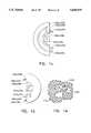
- the jaw cups 46a, 46bhave an eccentric, albeit symmetrical outline with their widest point indicated by the line 47. Distal of the line 47, the jaw cups are substantially hemispherical and proximal of the line 47, the jaw cups are substantially hemi-elliptical. The jaw cups are arranged so that the rims are substantially aligned when closed as shown in FIG. 5. It will also be seen from FIGS. 5 and 6 that the side walls 57, 57b, 59a, 59b of the jaw cups 46a, 46b taper towards the arms 50a, 50b to provide a smooth transition from the jaw cups to the arms.
- FIGS. 7a through 7ethe operation of the multiple sample bioptome of the invention is illustrated schematically in sequence.
- a first tissue sampleis taken by positioning the jaw cups 46a, 46b around a tissue 60 to be sampled.
- the handle 12 of the bioptome 10is operated as described above so that the cylindrical sleeve 40 is moved distally over the narrow arms 50a, 50b of the jaw assembly 44 to the position approximately shown in FIG. 7b.
- the jaw cups 46a, 46bare brought close to each other and the sharp rims 48a, 48b of the jaw cups 46a, 46b engage the tissue 60 and bite into it.
- the knife sharp edge 42 of the sleeve 40severs any tissue 60 extending from the lateral sides of the jaw cups 46a, 46b. A first sample 60a of the tissue 60 is thereby trapped between the jaw cups 46a, 46b and severed from the tissue 60.
- the coil 16is not free to stretch, as it is kept longitudinally stiff by the shrink wrap or sheath 15 which preferably extends along the length of the coil 16.
- a wirecan be used instead of the shrink wrap or sheath. The wire, which would typically be flat, would be attached to the proximal and distal ends of the coil to keep the coil in tension and prevent it from stretching as the sleeve is moved forward and a bite taken.
- FIGS. 7f-7hshow a top view of the sequence of operations depicted in side views in FIGS. 7a and 7b. From the top view of FIG. 7f, it can be seen that the tissue 60 extends beyond the sides of the jaw cups 46a, 46b. The knife-sharp distal edge 42 of the cylinder 40 severs the tissue 60 which extends beyond the cups so that the sample 60a can be removed from the tissue 60 as shown in FIGS. 7g and 7h.
- FIGS. 8a through 9bshow two other mechanisms for coupling the distal end of the control wire 18 with the sleeve.
- the distal end 18a of the control wire 18is provided with a Z-bend.
- the side wall of the cylindrical sleeve 40is punched with two spaced apart semicircular holes 145a, 145b leaving a bendable narrow strip 145c between them.
- the narrow strip 145cis bent radially inward a distance sufficient to accommodate the distal end 18a of the control wire 18.
- the Z-bend of the distal end 18a of the control wire 18is inserted through the space formed between the narrow strip 145c and the semicircular holes 145a, 145b as shown in FIGS. 8a and 8b.
- the push rod 318could move, and the tube 340 could be fixed.
- movement of the lever relative to the handlewould cause the end effectors 344a, 344b to be drawn into the tube 340, with the jaws closing, and with the jaws and the sharp end 342 of the tube 340 severing the tissue.
- a cautery contact 398is provided which contacts the rigid rod 318 and extends out of the fixed portion 324 of the handle 312.
- the tube 340is preferably provided with shrink wrap or other insulation 399.
- cauterizationwould be carried out after a sample is obtained and severed from the surgical site with the jaws still located at the surgical site. Because the body of the patient acts as the second electrode (ground), current flows from the jaws into the patient, at the surgical site, thereby effecting a cauterization of the surgical site rather than cauterizing the sample in the jaws.
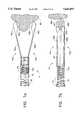
- FIGS. 13, 13a, and 13bshow a presently preferred embodiment of coupling a jaw assembly to the distal end of a coil.
- the jaw assembly 560includes a pair of end effectors 562a, 562b, a mounting screw 564, and a retaining sleeve or washer 566.
- Each end effector 562a, 562bincludes a jaw cup 568a, 568b and a resilient, preferably narrow, arm 570a, 570b which extends proximally from the cup.
- the proximal end of each arm 570a, 570bis provided with a mounting hole 572a, 572b.
- the end effectorsmay incorporate various features of the end effectors described above.
- the cross member 628is a disk segment having two opposite substantially parallel sides 628a, 628b, two curved sides 628c, 628d having radii of curvature which correspond to the inner radius of the cylindrical sleeve 640, and a central bore 628e.
- the distance between the parallel sides 628a and 628bis less than the distance between the interior surfaces of the arms 650a, 650b of the jaw assembly; and the distance between the curved sides 628c and 628d is substantially equal to the interior diameter of the cylindrical sleeve 640.
- the diameter of the bore 628eis substantially equal to the diameter of the control wire 618.
- the jawshave been disclosed as made out of a nickel-titanium alloy, they may also be made out of, e.g., iron-platinum, silver-cadmium, nickel-aluminum, manganese-copper, copper-zinc, nickel-thallium, or any other super-elastic alloy.
- the apparatus of the inventionwas described as advantageously permitting the obtaining of multiple biopsies without removal from the surgical site, the apparatus of the invention, if desired, could still be used for obtaining single biopsies at a time.
- the endoscopic instrumentneed not be used for taking biopsies at all, but could be used as a dissector.
- the tube which causes the arms to closewould not have a sharp end, and the end effectors could be paddle or otherwise shaped rather than having jaw cups.
- the actuation mechanism of the inventionit will be appreciated that other types of actuation mechanisms could be utilized.
- specific couplings of the ends of the coil. and control wirehave been shown, it will be recognized that other types of couplings could be used with similar results obtained.
- specific couplings of the ends of the rigid tube and rodhave been shown, it will be understood that other types of couplings could be used.
- particular configurationshave been disclosed in reference to the jaw assembly, it will be appreciated that other configurations could be used as well.
- the jawscan be provided with sharp teeth which, in conjunction with the sharp cylinder, will provide a cutting ability.
- the inner rodis shown to be stationary and the outer tube is shown to be adjustable, the outer tube may be made stationary and the rod adjustable.
Landscapes
- Health & Medical Sciences (AREA)
- Life Sciences & Earth Sciences (AREA)
- Surgery (AREA)
- Biomedical Technology (AREA)
- General Health & Medical Sciences (AREA)
- Heart & Thoracic Surgery (AREA)
- Medical Informatics (AREA)
- Molecular Biology (AREA)
- Pathology (AREA)
- Animal Behavior & Ethology (AREA)
- Engineering & Computer Science (AREA)
- Public Health (AREA)
- Veterinary Medicine (AREA)
- Biodiversity & Conservation Biology (AREA)
- Nuclear Medicine, Radiotherapy & Molecular Imaging (AREA)
- Surgical Instruments (AREA)
- Endoscopes (AREA)
Abstract
Description
Claims (28)
Priority Applications (10)
| Application Number | Priority Date | Filing Date | Title |
|---|---|---|---|
| US08/440,327US5645075A (en) | 1992-02-18 | 1995-05-12 | Jaw assembly for an endoscopic instrument |
| AU57486/96AAU5748696A (en) | 1995-05-12 | 1996-05-10 | Jaw assembly for an endoscopic instrument |
| EP96915816AEP0900050B1 (en) | 1995-05-12 | 1996-05-10 | Jaw assembly for an endoscopic instrument |
| DE69636081TDE69636081T2 (en) | 1995-05-12 | 1996-05-10 | Clamping jaw assembly for endoscopic instruments |
| US08/952,011US6099483A (en) | 1995-05-12 | 1996-05-10 | Jaw assembly for an endoscopic instrument |
| EP03076207AEP1350475B1 (en) | 1995-05-12 | 1996-05-10 | Jaw assembly for an endoscopic instrument |
| PCT/US1996/006925WO1996035382A1 (en) | 1995-05-12 | 1996-05-10 | Jaw assembly for an endoscopic instrument |
| DE69632872TDE69632872T2 (en) | 1995-05-12 | 1996-05-10 | BELT ARRANGEMENT FOR ENDOSCOPIC INSTRUMENTS |
| JP53433096AJP3696621B2 (en) | 1995-05-12 | 1996-05-10 | Jaw-like member assembly for endoscopic inspection instruments |
| US08/888,567US5840043A (en) | 1992-02-18 | 1997-07-07 | Jaw assembly for an endoscopic instrument |
Applications Claiming Priority (3)
| Application Number | Priority Date | Filing Date | Title |
|---|---|---|---|
| US07/837,046US5507296A (en) | 1990-05-10 | 1992-02-18 | Radial jaw biopsy forceps |
| US08/189,937US5542432A (en) | 1992-02-18 | 1994-02-01 | Endoscopic multiple sample bioptome |
| US08/440,327US5645075A (en) | 1992-02-18 | 1995-05-12 | Jaw assembly for an endoscopic instrument |
Related Parent Applications (1)
| Application Number | Title | Priority Date | Filing Date |
|---|---|---|---|
| US08/189,937Continuation-In-PartUS5542432A (en) | 1992-02-18 | 1994-02-01 | Endoscopic multiple sample bioptome |
Related Child Applications (2)
| Application Number | Title | Priority Date | Filing Date |
|---|---|---|---|
| US08/952,011ContinuationUS6099483A (en) | 1995-05-12 | 1996-05-10 | Jaw assembly for an endoscopic instrument |
| US08/888,567ContinuationUS5840043A (en) | 1992-02-18 | 1997-07-07 | Jaw assembly for an endoscopic instrument |
Publications (1)
| Publication Number | Publication Date |
|---|---|
| US5645075Atrue US5645075A (en) | 1997-07-08 |
Family
ID=23748335
Family Applications (3)
| Application Number | Title | Priority Date | Filing Date |
|---|---|---|---|
| US08/440,327Expired - LifetimeUS5645075A (en) | 1992-02-18 | 1995-05-12 | Jaw assembly for an endoscopic instrument |
| US08/952,011Expired - Fee RelatedUS6099483A (en) | 1995-05-12 | 1996-05-10 | Jaw assembly for an endoscopic instrument |
| US08/888,567Expired - LifetimeUS5840043A (en) | 1992-02-18 | 1997-07-07 | Jaw assembly for an endoscopic instrument |
Family Applications After (2)
| Application Number | Title | Priority Date | Filing Date |
|---|---|---|---|
| US08/952,011Expired - Fee RelatedUS6099483A (en) | 1995-05-12 | 1996-05-10 | Jaw assembly for an endoscopic instrument |
| US08/888,567Expired - LifetimeUS5840043A (en) | 1992-02-18 | 1997-07-07 | Jaw assembly for an endoscopic instrument |
Country Status (6)
| Country | Link |
|---|---|
| US (3) | US5645075A (en) |
| EP (2) | EP0900050B1 (en) |
| JP (1) | JP3696621B2 (en) |
| AU (1) | AU5748696A (en) |
| DE (2) | DE69632872T2 (en) |
| WO (1) | WO1996035382A1 (en) |
Cited By (74)
| Publication number | Priority date | Publication date | Assignee | Title |
|---|---|---|---|---|
| US5762069A (en)* | 1995-12-29 | 1998-06-09 | Akos Biomedical, Inc. | Multiple sample biopsy forceps |
| US5897507A (en)* | 1996-11-25 | 1999-04-27 | Symbiosis Corporation | Biopsy forceps instrument having irrigation and aspiration capabilities |
| US5967997A (en)* | 1998-04-30 | 1999-10-19 | Symbiosis Corporation | Endoscopic surgical instrument with deflectable and rotatable distal end |
| US6083150A (en)* | 1999-03-12 | 2000-07-04 | C. R. Bard, Inc. | Endoscopic multiple sample biopsy forceps |
| US6099483A (en)* | 1995-05-12 | 2000-08-08 | Symbiosis Corporation | Jaw assembly for an endoscopic instrument |
| US6110127A (en)* | 1998-02-17 | 2000-08-29 | Olympus Optical, Co., Ltd. | Medical instrument for use in combination with an endoscope |
| US6142956A (en) | 1996-11-25 | 2000-11-07 | Symbiosis Corporation | Proximal actuation handle for a biopsy forceps instrument having irrigation and aspiration capabilities |
| US20020029006A1 (en)* | 1996-11-25 | 2002-03-07 | Scimed Life Systems, Inc. | Biopsy instrument having irrigation and aspiration capabilities |
| US20020107457A1 (en)* | 1996-11-25 | 2002-08-08 | Francese Jose L. | Suction adapter for medical instrument |
| US6673078B1 (en)* | 2002-07-24 | 2004-01-06 | Robert H. Muncie | Surgical wire and pin extractor |
| US20050033354A1 (en)* | 2001-11-19 | 2005-02-10 | Scimed Life Systems, Inc. | Endoscopic surgical instrument |
| US20050054945A1 (en)* | 2003-09-10 | 2005-03-10 | Scimed Life Systems, Inc | Forceps and collection assembly with accompanying mechanisms and related methods of use |
| US20060036271A1 (en)* | 2004-07-29 | 2006-02-16 | X-Sten, Inc. | Spinal ligament modification devices |
| US20060129185A1 (en)* | 1999-10-25 | 2006-06-15 | Boston Scientific Scimed, Inc. | Forceps for medical use |
| US20060178699A1 (en)* | 2005-01-20 | 2006-08-10 | Wilson-Cook Medical Inc. | Biopsy forceps |
| US20060217699A1 (en)* | 1998-05-20 | 2006-09-28 | Wang Paul J | Cardiac ablation system and method for treatment of cardiac arrhthmias and transmyocardial revascularization |
| US20070027464A1 (en)* | 2005-07-29 | 2007-02-01 | X-Sten, Corp. | Device for resecting spinal tissue |
| US20070028473A1 (en)* | 2003-09-08 | 2007-02-08 | Trelleborg Automotive Technical Center Gmbh | Pendulum mount |
| US20070123890A1 (en)* | 2005-11-04 | 2007-05-31 | X-Sten, Corp. | Tissue retrieval devices and methods |
| US7241263B2 (en) | 2004-09-30 | 2007-07-10 | Scimed Life Systems, Inc. | Selectively rotatable shaft coupler |
| US20070244513A1 (en)* | 2006-04-14 | 2007-10-18 | Ethicon Endo-Surgery, Inc. | Endoscopic device |
| US7294139B1 (en) | 2002-07-26 | 2007-11-13 | C.M. Wright, Inc. | Controlled - motion endoscopic grasping instrument |
| US20070299459A1 (en)* | 2006-06-26 | 2007-12-27 | X-Sten Corp. | Percutaneous Tissue Access Device |
| US20080021278A1 (en)* | 2006-07-24 | 2008-01-24 | Leonard Robert F | Surgical device with removable end effector |
| US7413543B2 (en) | 2003-04-01 | 2008-08-19 | Scimed Life Systems, Inc. | Endoscope with actively cooled illumination sources |
| US7479106B2 (en) | 2004-09-30 | 2009-01-20 | Boston Scientific Scimed, Inc. | Automated control of irrigation and aspiration in a single-use endoscope |
| US20090152780A1 (en)* | 2006-10-10 | 2009-06-18 | Trelleborg Automotive Technical Centre Gmbh | Method for calibrating an elastomer spring of a mount, and mount produced according to the method |
| US7553275B2 (en) | 2004-08-31 | 2009-06-30 | Surgical Solutions Llc | Medical device with articulating shaft |
| USD598549S1 (en) | 2008-09-16 | 2009-08-18 | Vertos Medical, Inc. | Surgical trocar |
| US7578786B2 (en) | 2003-04-01 | 2009-08-25 | Boston Scientific Scimed, Inc. | Video endoscope |
| US7591783B2 (en) | 2003-04-01 | 2009-09-22 | Boston Scientific Scimed, Inc. | Articulation joint for video endoscope |
| US7597662B2 (en) | 2004-09-30 | 2009-10-06 | Boston Scientific Scimed, Inc. | Multi-fluid delivery system |
| USD606654S1 (en) | 2006-07-31 | 2009-12-22 | Vertos Medical, Inc. | Tissue excision device |
| USD610259S1 (en) | 2008-10-23 | 2010-02-16 | Vertos Medical, Inc. | Tissue modification device |
| USD611146S1 (en) | 2008-10-23 | 2010-03-02 | Vertos Medical, Inc. | Tissue modification device |
| US7670284B2 (en) | 2004-08-31 | 2010-03-02 | Surgical Solutions Llc | Medical device with articulating shaft |
| US20100152612A1 (en)* | 2008-12-12 | 2010-06-17 | Boston Scientific Scimed, Inc. | Endoscopes having multiple lumens for tissue acquisition and removal and related methods of use |
| USD619252S1 (en) | 2008-10-23 | 2010-07-06 | Vertos Medical, Inc. | Tissue modification device |
| USD619253S1 (en) | 2008-10-23 | 2010-07-06 | Vertos Medical, Inc. | Tissue modification device |
| US7762960B2 (en) | 2005-05-13 | 2010-07-27 | Boston Scientific Scimed, Inc. | Biopsy forceps assemblies |
| USD620593S1 (en) | 2006-07-31 | 2010-07-27 | Vertos Medical, Inc. | Tissue excision device |
| USD621939S1 (en) | 2008-10-23 | 2010-08-17 | Vertos Medical, Inc. | Tissue modification device |
| USD624181S1 (en)* | 2009-09-25 | 2010-09-21 | Sumitomo Bakelite Company, Ltd. | Air-tight valve for overtube |
| US7846107B2 (en) | 2005-05-13 | 2010-12-07 | Boston Scientific Scimed, Inc. | Endoscopic apparatus with integrated multiple biopsy device |
| US7857827B2 (en) | 2006-04-14 | 2010-12-28 | Ethicon Endo-Surgery, Inc. | Endoscopic device |
| USD635671S1 (en) | 2008-10-23 | 2011-04-05 | Vertos Medical, Inc. | Tissue modification device |
| US7942896B2 (en) | 2003-11-25 | 2011-05-17 | Scimed Life Systems, Inc. | Forceps and collection assembly and related methods of use and manufacture |
| US7942830B2 (en) | 2006-05-09 | 2011-05-17 | Vertos Medical, Inc. | Ipsilateral approach to minimally invasive ligament decompression procedure |
| US7955255B2 (en) | 2006-04-20 | 2011-06-07 | Boston Scientific Scimed, Inc. | Imaging assembly with transparent distal cap |
| US7967759B2 (en) | 2006-01-19 | 2011-06-28 | Boston Scientific Scimed, Inc. | Endoscopic system with integrated patient respiratory status indicator |
| US7998167B2 (en) | 2006-04-14 | 2011-08-16 | Ethicon Endo-Surgery, Inc. | End effector and method of manufacture |
| US20110264091A1 (en)* | 2010-04-26 | 2011-10-27 | Rachel Suzanne Koppleman | Apparatus and method for sealing specimen for retrieval |
| US8052597B2 (en) | 2005-08-30 | 2011-11-08 | Boston Scientific Scimed, Inc. | Method for forming an endoscope articulation joint |
| US8083671B2 (en) | 2004-09-30 | 2011-12-27 | Boston Scientific Scimed, Inc. | Fluid delivery system for use with an endoscope |
| US8097003B2 (en) | 2005-05-13 | 2012-01-17 | Boston Scientific Scimed, Inc. | Endoscopic apparatus with integrated variceal ligation device |
| US8118732B2 (en) | 2003-04-01 | 2012-02-21 | Boston Scientific Scimed, Inc. | Force feedback control system for video endoscope |
| US20120109185A1 (en)* | 2010-10-28 | 2012-05-03 | Pare Surgical, Inc. | Percutaneous tissue grasping apparatus and method |
| US20120116435A1 (en)* | 2010-05-12 | 2012-05-10 | Ravi Nallakrishnan | Handle for Surgical Forceps and the Like |
| US8199187B2 (en) | 2004-09-30 | 2012-06-12 | Boston Scientific Scimed, Inc. | Adapter for use with digital imaging medical device |
| US8202265B2 (en) | 2006-04-20 | 2012-06-19 | Boston Scientific Scimed, Inc. | Multiple lumen assembly for use in endoscopes or other medical devices |
| US20120165797A1 (en)* | 2008-10-03 | 2012-06-28 | Tyco Healthcare Group Lp | Method of Transferring Rotational Motion in an Articulating Surgical Instrument |
| US8298244B2 (en) | 2006-10-26 | 2012-10-30 | Tyco Healtcare Group Lp | Intracorporeal grasping device |
| US8313500B2 (en) | 2006-04-14 | 2012-11-20 | Ethicon Endo-Surgery, Inc. | Endoscopic device |
| US8353860B2 (en) | 2004-09-30 | 2013-01-15 | Boston Scientific Scimed, Inc. | Device for obstruction removal with specific tip structure |
| US8357148B2 (en) | 2004-09-30 | 2013-01-22 | Boston Scientific Scimed, Inc. | Multi-functional endoscopic system for use in electrosurgical applications |
| US8469993B2 (en) | 2003-06-18 | 2013-06-25 | Boston Scientific Scimed, Inc. | Endoscopic instruments |
| US8535219B2 (en) | 2003-04-01 | 2013-09-17 | Boston Scientific Scimed, Inc. | Fluid manifold for endoscope system |
| US8888684B2 (en) | 2006-03-27 | 2014-11-18 | Boston Scientific Scimed, Inc. | Medical devices with local drug delivery capabilities |
| EP2907459B1 (en) | 2001-10-05 | 2016-09-14 | Boston Scientific Limited | Medical device for causing hemostasis |
| US9681857B2 (en) | 2003-06-18 | 2017-06-20 | Boston Scientific Scimed, Inc. | Endoscopic instruments and methods of manufacture |
| US11273247B1 (en)* | 2018-06-05 | 2022-03-15 | Vernon Bradley Taylor | Airway management device |
| US11576682B2 (en) | 2009-12-22 | 2023-02-14 | Cook Medical Technologies Llc | Medical devices with detachable pivotable jaws |
| US12102348B2 (en) | 2016-09-07 | 2024-10-01 | Vertos Medical, Inc. | Percutaneous lateral recess resection methods and instruments |
| US12324572B2 (en) | 2022-06-16 | 2025-06-10 | Vertos Medical, Inc. | Integrated instrument assembly |
Families Citing this family (214)
| Publication number | Priority date | Publication date | Assignee | Title |
|---|---|---|---|---|
| US6293282B1 (en)* | 1996-11-05 | 2001-09-25 | Jerome Lemelson | System and method for treating select tissue in living being |
| WO1998040008A1 (en) | 1997-03-13 | 1998-09-17 | Biomax Technologies, Inc. | Validating and processing fluorescence spectral data for detecting the rejection of transplanted tissue |
| FR2766084A1 (en)* | 1997-07-21 | 1999-01-22 | Duche Mathieu J B | Supple or rigid endoscopic or coeloscopic surgical instrument |
| US6387110B1 (en)* | 1999-06-23 | 2002-05-14 | Smith & Nephew, Inc. | Coating for surgical blades |
| US6537205B1 (en) | 1999-10-14 | 2003-03-25 | Scimed Life Systems, Inc. | Endoscopic instrument system having reduced backlash control wire action |
| US6743185B2 (en)* | 2000-09-26 | 2004-06-01 | Scimed Life Systems, Inc. | Handle assembly for surgical instrument and method of making the assembly |
| AU2002235351A1 (en) | 2001-01-26 | 2002-08-06 | Osteotech, Inc. | Implant insertion tool |
| US7341564B2 (en) | 2001-05-03 | 2008-03-11 | Boston Scientific Scimed, Inc. | Biopsy forceps device with transparent outer sheath |
| US11229472B2 (en) | 2001-06-12 | 2022-01-25 | Cilag Gmbh International | Modular battery powered handheld surgical instrument with multiple magnetic position sensors |
| EP1439802A2 (en)* | 2001-10-30 | 2004-07-28 | Osteotech, Inc. | Bone implant and insertion tools |
| US6989020B2 (en) | 2001-11-15 | 2006-01-24 | Cordis Neurovascular, Inc. | Embolic coil retrieval system |
| US20040044346A1 (en)* | 2002-09-03 | 2004-03-04 | Boury Harb N. | Surgical tool with disposable/removable cutting tip |
| WO2004084742A1 (en) | 2003-03-24 | 2004-10-07 | Theken Surgical Llc | Spinal implant adjustment device |
| US8182501B2 (en) | 2004-02-27 | 2012-05-22 | Ethicon Endo-Surgery, Inc. | Ultrasonic surgical shears and method for sealing a blood vessel using same |
| US7544208B1 (en) | 2004-05-03 | 2009-06-09 | Theken Spine, Llc | Adjustable corpectomy apparatus |
| US20060079879A1 (en) | 2004-10-08 | 2006-04-13 | Faller Craig N | Actuation mechanism for use with an ultrasonic surgical instrument |
| US7988699B2 (en)* | 2004-10-19 | 2011-08-02 | Warsaw Orthopedic, Inc. | Adjustable instrumentation for spinal implant insertion |
| US20070191713A1 (en) | 2005-10-14 | 2007-08-16 | Eichmann Stephen E | Ultrasonic device for cutting and coagulating |
| EP2193748A1 (en) | 2006-01-12 | 2010-06-09 | Multi Biopsy Sampling Co. Aps | A sampling apparatus for taking one or more samples |
| US7621930B2 (en) | 2006-01-20 | 2009-11-24 | Ethicon Endo-Surgery, Inc. | Ultrasound medical instrument having a medical ultrasonic blade |
| US7918783B2 (en) | 2006-03-22 | 2011-04-05 | Boston Scientific Scimed, Inc. | Endoscope working channel with multiple functionality |
| US8057498B2 (en) | 2007-11-30 | 2011-11-15 | Ethicon Endo-Surgery, Inc. | Ultrasonic surgical instrument blades |
| US8911460B2 (en) | 2007-03-22 | 2014-12-16 | Ethicon Endo-Surgery, Inc. | Ultrasonic surgical instruments |
| US8142461B2 (en) | 2007-03-22 | 2012-03-27 | Ethicon Endo-Surgery, Inc. | Surgical instruments |
| US8808319B2 (en) | 2007-07-27 | 2014-08-19 | Ethicon Endo-Surgery, Inc. | Surgical instruments |
| US8523889B2 (en) | 2007-07-27 | 2013-09-03 | Ethicon Endo-Surgery, Inc. | Ultrasonic end effectors with increased active length |
| US8430898B2 (en) | 2007-07-31 | 2013-04-30 | Ethicon Endo-Surgery, Inc. | Ultrasonic surgical instruments |
| US8512365B2 (en) | 2007-07-31 | 2013-08-20 | Ethicon Endo-Surgery, Inc. | Surgical instruments |
| US9044261B2 (en) | 2007-07-31 | 2015-06-02 | Ethicon Endo-Surgery, Inc. | Temperature controlled ultrasonic surgical instruments |
| EP2217157A2 (en) | 2007-10-05 | 2010-08-18 | Ethicon Endo-Surgery, Inc. | Ergonomic surgical instruments |
| US10010339B2 (en) | 2007-11-30 | 2018-07-03 | Ethicon Llc | Ultrasonic surgical blades |
| US9089360B2 (en) | 2008-08-06 | 2015-07-28 | Ethicon Endo-Surgery, Inc. | Devices and techniques for cutting and coagulating tissue |
| US9700339B2 (en) | 2009-05-20 | 2017-07-11 | Ethicon Endo-Surgery, Inc. | Coupling arrangements and methods for attaching tools to ultrasonic surgical instruments |
| US8663220B2 (en) | 2009-07-15 | 2014-03-04 | Ethicon Endo-Surgery, Inc. | Ultrasonic surgical instruments |
| US8939974B2 (en) | 2009-10-09 | 2015-01-27 | Ethicon Endo-Surgery, Inc. | Surgical instrument comprising first and second drive systems actuatable by a common trigger mechanism |
| US10172669B2 (en) | 2009-10-09 | 2019-01-08 | Ethicon Llc | Surgical instrument comprising an energy trigger lockout |
| US8747404B2 (en) | 2009-10-09 | 2014-06-10 | Ethicon Endo-Surgery, Inc. | Surgical instrument for transmitting energy to tissue comprising non-conductive grasping portions |
| US9050093B2 (en) | 2009-10-09 | 2015-06-09 | Ethicon Endo-Surgery, Inc. | Surgical generator for ultrasonic and electrosurgical devices |
| US8574231B2 (en) | 2009-10-09 | 2013-11-05 | Ethicon Endo-Surgery, Inc. | Surgical instrument for transmitting energy to tissue comprising a movable electrode or insulator |
| US11090104B2 (en) | 2009-10-09 | 2021-08-17 | Cilag Gmbh International | Surgical generator for ultrasonic and electrosurgical devices |
| US10441345B2 (en) | 2009-10-09 | 2019-10-15 | Ethicon Llc | Surgical generator for ultrasonic and electrosurgical devices |
| US8906016B2 (en) | 2009-10-09 | 2014-12-09 | Ethicon Endo-Surgery, Inc. | Surgical instrument for transmitting energy to tissue comprising steam control paths |
| US8951272B2 (en) | 2010-02-11 | 2015-02-10 | Ethicon Endo-Surgery, Inc. | Seal arrangements for ultrasonically powered surgical instruments |
| US8469981B2 (en) | 2010-02-11 | 2013-06-25 | Ethicon Endo-Surgery, Inc. | Rotatable cutting implement arrangements for ultrasonic surgical instruments |
| US8486096B2 (en) | 2010-02-11 | 2013-07-16 | Ethicon Endo-Surgery, Inc. | Dual purpose surgical instrument for cutting and coagulating tissue |
| US8696665B2 (en)* | 2010-03-26 | 2014-04-15 | Ethicon Endo-Surgery, Inc. | Surgical cutting and sealing instrument with reduced firing force |
| US8496682B2 (en) | 2010-04-12 | 2013-07-30 | Ethicon Endo-Surgery, Inc. | Electrosurgical cutting and sealing instruments with cam-actuated jaws |
| US8709035B2 (en) | 2010-04-12 | 2014-04-29 | Ethicon Endo-Surgery, Inc. | Electrosurgical cutting and sealing instruments with jaws having a parallel closure motion |
| US8834518B2 (en) | 2010-04-12 | 2014-09-16 | Ethicon Endo-Surgery, Inc. | Electrosurgical cutting and sealing instruments with cam-actuated jaws |
| US8535311B2 (en) | 2010-04-22 | 2013-09-17 | Ethicon Endo-Surgery, Inc. | Electrosurgical instrument comprising closing and firing systems |
| US8685020B2 (en) | 2010-05-17 | 2014-04-01 | Ethicon Endo-Surgery, Inc. | Surgical instruments and end effectors therefor |
| GB2480498A (en) | 2010-05-21 | 2011-11-23 | Ethicon Endo Surgery Inc | Medical device comprising RF circuitry |
| US8926607B2 (en) | 2010-06-09 | 2015-01-06 | Ethicon Endo-Surgery, Inc. | Electrosurgical instrument employing multiple positive temperature coefficient electrodes |
| US8795276B2 (en) | 2010-06-09 | 2014-08-05 | Ethicon Endo-Surgery, Inc. | Electrosurgical instrument employing a plurality of electrodes |
| US8790342B2 (en) | 2010-06-09 | 2014-07-29 | Ethicon Endo-Surgery, Inc. | Electrosurgical instrument employing pressure-variation electrodes |
| US8888776B2 (en) | 2010-06-09 | 2014-11-18 | Ethicon Endo-Surgery, Inc. | Electrosurgical instrument employing an electrode |
| US9005199B2 (en) | 2010-06-10 | 2015-04-14 | Ethicon Endo-Surgery, Inc. | Heat management configurations for controlling heat dissipation from electrosurgical instruments |
| US8764747B2 (en) | 2010-06-10 | 2014-07-01 | Ethicon Endo-Surgery, Inc. | Electrosurgical instrument comprising sequentially activated electrodes |
| US8753338B2 (en) | 2010-06-10 | 2014-06-17 | Ethicon Endo-Surgery, Inc. | Electrosurgical instrument employing a thermal management system |
| US9149324B2 (en) | 2010-07-08 | 2015-10-06 | Ethicon Endo-Surgery, Inc. | Surgical instrument comprising an articulatable end effector |
| US8453906B2 (en) | 2010-07-14 | 2013-06-04 | Ethicon Endo-Surgery, Inc. | Surgical instruments with electrodes |
| US20120016413A1 (en) | 2010-07-14 | 2012-01-19 | Ethicon Endo-Surgery, Inc. | Surgical fastening devices comprising rivets |
| US8795327B2 (en) | 2010-07-22 | 2014-08-05 | Ethicon Endo-Surgery, Inc. | Electrosurgical instrument with separate closure and cutting members |
| US9192431B2 (en) | 2010-07-23 | 2015-11-24 | Ethicon Endo-Surgery, Inc. | Electrosurgical cutting and sealing instrument |
| US9011437B2 (en) | 2010-07-23 | 2015-04-21 | Ethicon Endo-Surgery, Inc. | Electrosurgical cutting and sealing instrument |
| US8979844B2 (en) | 2010-07-23 | 2015-03-17 | Ethicon Endo-Surgery, Inc. | Electrosurgical cutting and sealing instrument |
| US8979843B2 (en) | 2010-07-23 | 2015-03-17 | Ethicon Endo-Surgery, Inc. | Electrosurgical cutting and sealing instrument |
| US8702704B2 (en) | 2010-07-23 | 2014-04-22 | Ethicon Endo-Surgery, Inc. | Electrosurgical cutting and sealing instrument |
| US8979890B2 (en) | 2010-10-01 | 2015-03-17 | Ethicon Endo-Surgery, Inc. | Surgical instrument with jaw member |
| US8628529B2 (en) | 2010-10-26 | 2014-01-14 | Ethicon Endo-Surgery, Inc. | Surgical instrument with magnetic clamping force |
| US8715277B2 (en) | 2010-12-08 | 2014-05-06 | Ethicon Endo-Surgery, Inc. | Control of jaw compression in surgical instrument having end effector with opposing jaw members |
| US8573912B2 (en) | 2011-02-03 | 2013-11-05 | Kennametal Inc. | Fastener for attaching a milling cutter body to an adaptor and method of installing same |
| US9259265B2 (en) | 2011-07-22 | 2016-02-16 | Ethicon Endo-Surgery, Llc | Surgical instruments for tensioning tissue |
| US8784442B2 (en) | 2011-08-19 | 2014-07-22 | Empirilon Technology, Llc | Methods and systems for performing thrombectomy procedures |
| US20130046334A1 (en)* | 2011-08-19 | 2013-02-21 | Donald K. Jones | Intralumenal retrieval system |
| US9044243B2 (en) | 2011-08-30 | 2015-06-02 | Ethcon Endo-Surgery, Inc. | Surgical cutting and fastening device with descendible second trigger arrangement |
| US9333025B2 (en) | 2011-10-24 | 2016-05-10 | Ethicon Endo-Surgery, Llc | Battery initialization clip |
| WO2013119545A1 (en) | 2012-02-10 | 2013-08-15 | Ethicon-Endo Surgery, Inc. | Robotically controlled surgical instrument |
| US9439668B2 (en) | 2012-04-09 | 2016-09-13 | Ethicon Endo-Surgery, Llc | Switch arrangements for ultrasonic surgical instruments |
| US8632540B2 (en)* | 2012-04-11 | 2014-01-21 | ENT Biotech Solutions, LLC | Surgical instrument for tissue removal |
| US20140005705A1 (en) | 2012-06-29 | 2014-01-02 | Ethicon Endo-Surgery, Inc. | Surgical instruments with articulating shafts |
| US20140005640A1 (en) | 2012-06-28 | 2014-01-02 | Ethicon Endo-Surgery, Inc. | Surgical end effector jaw and electrode configurations |
| US9226767B2 (en) | 2012-06-29 | 2016-01-05 | Ethicon Endo-Surgery, Inc. | Closed feedback control for electrosurgical device |
| US9198714B2 (en) | 2012-06-29 | 2015-12-01 | Ethicon Endo-Surgery, Inc. | Haptic feedback devices for surgical robot |
| US9408622B2 (en) | 2012-06-29 | 2016-08-09 | Ethicon Endo-Surgery, Llc | Surgical instruments with articulating shafts |
| US20140005702A1 (en) | 2012-06-29 | 2014-01-02 | Ethicon Endo-Surgery, Inc. | Ultrasonic surgical instruments with distally positioned transducers |
| US9393037B2 (en) | 2012-06-29 | 2016-07-19 | Ethicon Endo-Surgery, Llc | Surgical instruments with articulating shafts |
| US9351754B2 (en) | 2012-06-29 | 2016-05-31 | Ethicon Endo-Surgery, Llc | Ultrasonic surgical instruments with distally positioned jaw assemblies |
| US9326788B2 (en) | 2012-06-29 | 2016-05-03 | Ethicon Endo-Surgery, Llc | Lockout mechanism for use with robotic electrosurgical device |
| US9820768B2 (en) | 2012-06-29 | 2017-11-21 | Ethicon Llc | Ultrasonic surgical instruments with control mechanisms |
| EP2900158B1 (en) | 2012-09-28 | 2020-04-15 | Ethicon LLC | Multi-function bi-polar forceps |
| US9095367B2 (en) | 2012-10-22 | 2015-08-04 | Ethicon Endo-Surgery, Inc. | Flexible harmonic waveguides/blades for surgical instruments |
| US20140135804A1 (en) | 2012-11-15 | 2014-05-15 | Ethicon Endo-Surgery, Inc. | Ultrasonic and electrosurgical devices |
| US9427251B2 (en) | 2013-03-13 | 2016-08-30 | Covidien Lp | Saber tooth harvester |
| US10226273B2 (en) | 2013-03-14 | 2019-03-12 | Ethicon Llc | Mechanical fasteners for use with surgical energy devices |
| US9295514B2 (en) | 2013-08-30 | 2016-03-29 | Ethicon Endo-Surgery, Llc | Surgical devices with close quarter articulation features |
| US9814514B2 (en) | 2013-09-13 | 2017-11-14 | Ethicon Llc | Electrosurgical (RF) medical instruments for cutting and coagulating tissue |
| US9861428B2 (en) | 2013-09-16 | 2018-01-09 | Ethicon Llc | Integrated systems for electrosurgical steam or smoke control |
| US9265926B2 (en) | 2013-11-08 | 2016-02-23 | Ethicon Endo-Surgery, Llc | Electrosurgical devices |
| US9526565B2 (en) | 2013-11-08 | 2016-12-27 | Ethicon Endo-Surgery, Llc | Electrosurgical devices |
| GB2521229A (en) | 2013-12-16 | 2015-06-17 | Ethicon Endo Surgery Inc | Medical device |
| GB2521228A (en) | 2013-12-16 | 2015-06-17 | Ethicon Endo Surgery Inc | Medical device |
| US9795436B2 (en) | 2014-01-07 | 2017-10-24 | Ethicon Llc | Harvesting energy from a surgical generator |
| US9408660B2 (en) | 2014-01-17 | 2016-08-09 | Ethicon Endo-Surgery, Llc | Device trigger dampening mechanism |
| US9554854B2 (en) | 2014-03-18 | 2017-01-31 | Ethicon Endo-Surgery, Llc | Detecting short circuits in electrosurgical medical devices |
| US10463421B2 (en) | 2014-03-27 | 2019-11-05 | Ethicon Llc | Two stage trigger, clamp and cut bipolar vessel sealer |
| US10092310B2 (en) | 2014-03-27 | 2018-10-09 | Ethicon Llc | Electrosurgical devices |
| US10524852B1 (en) | 2014-03-28 | 2020-01-07 | Ethicon Llc | Distal sealing end effector with spacers |
| US9737355B2 (en) | 2014-03-31 | 2017-08-22 | Ethicon Llc | Controlling impedance rise in electrosurgical medical devices |
| US9913680B2 (en) | 2014-04-15 | 2018-03-13 | Ethicon Llc | Software algorithms for electrosurgical instruments |
| US9757186B2 (en) | 2014-04-17 | 2017-09-12 | Ethicon Llc | Device status feedback for bipolar tissue spacer |
| US9700333B2 (en) | 2014-06-30 | 2017-07-11 | Ethicon Llc | Surgical instrument with variable tissue compression |
| US10348941B2 (en) | 2014-07-30 | 2019-07-09 | Karl Storz Endovision, Inc. | Durable flexible circuit assembly |
| US10285724B2 (en) | 2014-07-31 | 2019-05-14 | Ethicon Llc | Actuation mechanisms and load adjustment assemblies for surgical instruments |
| US10194976B2 (en) | 2014-08-25 | 2019-02-05 | Ethicon Llc | Lockout disabling mechanism |
| US9877776B2 (en) | 2014-08-25 | 2018-01-30 | Ethicon Llc | Simultaneous I-beam and spring driven cam jaw closure mechanism |
| US10194972B2 (en) | 2014-08-26 | 2019-02-05 | Ethicon Llc | Managing tissue treatment |
| US10639092B2 (en) | 2014-12-08 | 2020-05-05 | Ethicon Llc | Electrode configurations for surgical instruments |
| US10111699B2 (en) | 2014-12-22 | 2018-10-30 | Ethicon Llc | RF tissue sealer, shear grip, trigger lock mechanism and energy activation |
| US9848937B2 (en) | 2014-12-22 | 2017-12-26 | Ethicon Llc | End effector with detectable configurations |
| US10159524B2 (en) | 2014-12-22 | 2018-12-25 | Ethicon Llc | High power battery powered RF amplifier topology |
| US10092348B2 (en) | 2014-12-22 | 2018-10-09 | Ethicon Llc | RF tissue sealer, shear grip, trigger lock mechanism and energy activation |
| US10245095B2 (en) | 2015-02-06 | 2019-04-02 | Ethicon Llc | Electrosurgical instrument with rotation and articulation mechanisms |
| US10342602B2 (en) | 2015-03-17 | 2019-07-09 | Ethicon Llc | Managing tissue treatment |
| US10321950B2 (en) | 2015-03-17 | 2019-06-18 | Ethicon Llc | Managing tissue treatment |
| US10595929B2 (en) | 2015-03-24 | 2020-03-24 | Ethicon Llc | Surgical instruments with firing system overload protection mechanisms |
| US10314638B2 (en) | 2015-04-07 | 2019-06-11 | Ethicon Llc | Articulating radio frequency (RF) tissue seal with articulating state sensing |
| US10117702B2 (en) | 2015-04-10 | 2018-11-06 | Ethicon Llc | Surgical generator systems and related methods |
| US10130410B2 (en) | 2015-04-17 | 2018-11-20 | Ethicon Llc | Electrosurgical instrument including a cutting member decouplable from a cutting member trigger |
| US9872725B2 (en) | 2015-04-29 | 2018-01-23 | Ethicon Llc | RF tissue sealer with mode selection |
| US11020140B2 (en) | 2015-06-17 | 2021-06-01 | Cilag Gmbh International | Ultrasonic surgical blade for use with ultrasonic surgical instruments |
| US11129669B2 (en) | 2015-06-30 | 2021-09-28 | Cilag Gmbh International | Surgical system with user adaptable techniques based on tissue type |
| US11051873B2 (en) | 2015-06-30 | 2021-07-06 | Cilag Gmbh International | Surgical system with user adaptable techniques employing multiple energy modalities based on tissue parameters |
| US10357303B2 (en) | 2015-06-30 | 2019-07-23 | Ethicon Llc | Translatable outer tube for sealing using shielded lap chole dissector |
| US10034704B2 (en) | 2015-06-30 | 2018-07-31 | Ethicon Llc | Surgical instrument with user adaptable algorithms |
| US11141213B2 (en) | 2015-06-30 | 2021-10-12 | Cilag Gmbh International | Surgical instrument with user adaptable techniques |
| US10898256B2 (en) | 2015-06-30 | 2021-01-26 | Ethicon Llc | Surgical system with user adaptable techniques based on tissue impedance |
| US10154852B2 (en) | 2015-07-01 | 2018-12-18 | Ethicon Llc | Ultrasonic surgical blade with improved cutting and coagulation features |
| US10194973B2 (en) | 2015-09-30 | 2019-02-05 | Ethicon Llc | Generator for digitally generating electrical signal waveforms for electrosurgical and ultrasonic surgical instruments |
| US10959771B2 (en) | 2015-10-16 | 2021-03-30 | Ethicon Llc | Suction and irrigation sealing grasper |
| US10595930B2 (en) | 2015-10-16 | 2020-03-24 | Ethicon Llc | Electrode wiping surgical device |
| US10179022B2 (en) | 2015-12-30 | 2019-01-15 | Ethicon Llc | Jaw position impedance limiter for electrosurgical instrument |
| US10959806B2 (en) | 2015-12-30 | 2021-03-30 | Ethicon Llc | Energized medical device with reusable handle |
| US10575892B2 (en) | 2015-12-31 | 2020-03-03 | Ethicon Llc | Adapter for electrical surgical instruments |
| US10716615B2 (en) | 2016-01-15 | 2020-07-21 | Ethicon Llc | Modular battery powered handheld surgical instrument with curved end effectors having asymmetric engagement between jaw and blade |
| US11051840B2 (en) | 2016-01-15 | 2021-07-06 | Ethicon Llc | Modular battery powered handheld surgical instrument with reusable asymmetric handle housing |
| US11129670B2 (en) | 2016-01-15 | 2021-09-28 | Cilag Gmbh International | Modular battery powered handheld surgical instrument with selective application of energy based on button displacement, intensity, or local tissue characterization |
| US12193698B2 (en) | 2016-01-15 | 2025-01-14 | Cilag Gmbh International | Method for self-diagnosing operation of a control switch in a surgical instrument system |
| US11229471B2 (en) | 2016-01-15 | 2022-01-25 | Cilag Gmbh International | Modular battery powered handheld surgical instrument with selective application of energy based on tissue characterization |
| US10555769B2 (en) | 2016-02-22 | 2020-02-11 | Ethicon Llc | Flexible circuits for electrosurgical instrument |
| US10856934B2 (en) | 2016-04-29 | 2020-12-08 | Ethicon Llc | Electrosurgical instrument with electrically conductive gap setting and tissue engaging members |
| US10485607B2 (en) | 2016-04-29 | 2019-11-26 | Ethicon Llc | Jaw structure with distal closure for electrosurgical instruments |
| US10987156B2 (en) | 2016-04-29 | 2021-04-27 | Ethicon Llc | Electrosurgical instrument with electrically conductive gap setting member and electrically insulative tissue engaging members |
| US10702329B2 (en) | 2016-04-29 | 2020-07-07 | Ethicon Llc | Jaw structure with distal post for electrosurgical instruments |
| US10646269B2 (en) | 2016-04-29 | 2020-05-12 | Ethicon Llc | Non-linear jaw gap for electrosurgical instruments |
| US10456193B2 (en) | 2016-05-03 | 2019-10-29 | Ethicon Llc | Medical device with a bilateral jaw configuration for nerve stimulation |
| US10245064B2 (en) | 2016-07-12 | 2019-04-02 | Ethicon Llc | Ultrasonic surgical instrument with piezoelectric central lumen transducer |
| US10893883B2 (en) | 2016-07-13 | 2021-01-19 | Ethicon Llc | Ultrasonic assembly for use with ultrasonic surgical instruments |
| US10842522B2 (en) | 2016-07-15 | 2020-11-24 | Ethicon Llc | Ultrasonic surgical instruments having offset blades |
| US10376305B2 (en) | 2016-08-05 | 2019-08-13 | Ethicon Llc | Methods and systems for advanced harmonic energy |
| US10285723B2 (en) | 2016-08-09 | 2019-05-14 | Ethicon Llc | Ultrasonic surgical blade with improved heel portion |
| USD847990S1 (en) | 2016-08-16 | 2019-05-07 | Ethicon Llc | Surgical instrument |
| US10952759B2 (en) | 2016-08-25 | 2021-03-23 | Ethicon Llc | Tissue loading of a surgical instrument |
| US10736649B2 (en) | 2016-08-25 | 2020-08-11 | Ethicon Llc | Electrical and thermal connections for ultrasonic transducer |
| US10751117B2 (en) | 2016-09-23 | 2020-08-25 | Ethicon Llc | Electrosurgical instrument with fluid diverter |
| JP6822481B2 (en)* | 2016-09-30 | 2021-01-27 | 日本ゼオン株式会社 | Clip removal device |
| US10603064B2 (en) | 2016-11-28 | 2020-03-31 | Ethicon Llc | Ultrasonic transducer |
| US11266430B2 (en) | 2016-11-29 | 2022-03-08 | Cilag Gmbh International | End effector control and calibration |
| US11744602B2 (en)* | 2017-02-15 | 2023-09-05 | Transmed7, Llc | Advanced minimally invasive multi-functional robotic surgical devices and methods |
| US11033325B2 (en) | 2017-02-16 | 2021-06-15 | Cilag Gmbh International | Electrosurgical instrument with telescoping suction port and debris cleaner |
| US10799284B2 (en) | 2017-03-15 | 2020-10-13 | Ethicon Llc | Electrosurgical instrument with textured jaws |
| US11497546B2 (en) | 2017-03-31 | 2022-11-15 | Cilag Gmbh International | Area ratios of patterned coatings on RF electrodes to reduce sticking |
| US10603117B2 (en) | 2017-06-28 | 2020-03-31 | Ethicon Llc | Articulation state detection mechanisms |
| US10820920B2 (en) | 2017-07-05 | 2020-11-03 | Ethicon Llc | Reusable ultrasonic medical devices and methods of their use |
| US11484358B2 (en) | 2017-09-29 | 2022-11-01 | Cilag Gmbh International | Flexible electrosurgical instrument |
| US11490951B2 (en) | 2017-09-29 | 2022-11-08 | Cilag Gmbh International | Saline contact with electrodes |
| US11033323B2 (en) | 2017-09-29 | 2021-06-15 | Cilag Gmbh International | Systems and methods for managing fluid and suction in electrosurgical systems |
| CN109009410A (en)* | 2018-06-13 | 2018-12-18 | 东莞市联洲知识产权运营管理有限公司 | Improved tong head structure on electric coagulation tong |
| US11376082B2 (en) | 2019-06-27 | 2022-07-05 | Cilag Gmbh International | Robotic surgical system with local sensing of functional parameters based on measurements of multiple physical inputs |
| US11547468B2 (en) | 2019-06-27 | 2023-01-10 | Cilag Gmbh International | Robotic surgical system with safety and cooperative sensing control |
| US11413102B2 (en) | 2019-06-27 | 2022-08-16 | Cilag Gmbh International | Multi-access port for surgical robotic systems |
| US11723729B2 (en) | 2019-06-27 | 2023-08-15 | Cilag Gmbh International | Robotic surgical assembly coupling safety mechanisms |
| US11612445B2 (en) | 2019-06-27 | 2023-03-28 | Cilag Gmbh International | Cooperative operation of robotic arms |
| US11607278B2 (en) | 2019-06-27 | 2023-03-21 | Cilag Gmbh International | Cooperative robotic surgical systems |
| US11452525B2 (en) | 2019-12-30 | 2022-09-27 | Cilag Gmbh International | Surgical instrument comprising an adjustment system |
| US12343063B2 (en) | 2019-12-30 | 2025-07-01 | Cilag Gmbh International | Multi-layer clamp arm pad for enhanced versatility and performance of a surgical device |
| US11786294B2 (en) | 2019-12-30 | 2023-10-17 | Cilag Gmbh International | Control program for modular combination energy device |
| US11937863B2 (en) | 2019-12-30 | 2024-03-26 | Cilag Gmbh International | Deflectable electrode with variable compression bias along the length of the deflectable electrode |
| US11696776B2 (en) | 2019-12-30 | 2023-07-11 | Cilag Gmbh International | Articulatable surgical instrument |
| US12082808B2 (en) | 2019-12-30 | 2024-09-10 | Cilag Gmbh International | Surgical instrument comprising a control system responsive to software configurations |
| US11812957B2 (en) | 2019-12-30 | 2023-11-14 | Cilag Gmbh International | Surgical instrument comprising a signal interference resolution system |
| US11779329B2 (en) | 2019-12-30 | 2023-10-10 | Cilag Gmbh International | Surgical instrument comprising a flex circuit including a sensor system |
| US12114912B2 (en) | 2019-12-30 | 2024-10-15 | Cilag Gmbh International | Non-biased deflectable electrode to minimize contact between ultrasonic blade and electrode |
| US11986201B2 (en) | 2019-12-30 | 2024-05-21 | Cilag Gmbh International | Method for operating a surgical instrument |
| US12023086B2 (en) | 2019-12-30 | 2024-07-02 | Cilag Gmbh International | Electrosurgical instrument for delivering blended energy modalities to tissue |
| US11786291B2 (en) | 2019-12-30 | 2023-10-17 | Cilag Gmbh International | Deflectable support of RF energy electrode with respect to opposing ultrasonic blade |
| US11779387B2 (en) | 2019-12-30 | 2023-10-10 | Cilag Gmbh International | Clamp arm jaw to minimize tissue sticking and improve tissue control |
| US11660089B2 (en) | 2019-12-30 | 2023-05-30 | Cilag Gmbh International | Surgical instrument comprising a sensing system |
| US12262937B2 (en) | 2019-12-30 | 2025-04-01 | Cilag Gmbh International | User interface for surgical instrument with combination energy modality end-effector |
| US11684412B2 (en) | 2019-12-30 | 2023-06-27 | Cilag Gmbh International | Surgical instrument with rotatable and articulatable surgical end effector |
| US11911063B2 (en) | 2019-12-30 | 2024-02-27 | Cilag Gmbh International | Techniques for detecting ultrasonic blade to electrode contact and reducing power to ultrasonic blade |
| US12053224B2 (en) | 2019-12-30 | 2024-08-06 | Cilag Gmbh International | Variation in electrode parameters and deflectable electrode to modify energy density and tissue interaction |
| US11950797B2 (en) | 2019-12-30 | 2024-04-09 | Cilag Gmbh International | Deflectable electrode with higher distal bias relative to proximal bias |
| US12336747B2 (en) | 2019-12-30 | 2025-06-24 | Cilag Gmbh International | Method of operating a combination ultrasonic / bipolar RF surgical device with a combination energy modality end-effector |
| US11937866B2 (en) | 2019-12-30 | 2024-03-26 | Cilag Gmbh International | Method for an electrosurgical procedure |
| US12064109B2 (en) | 2019-12-30 | 2024-08-20 | Cilag Gmbh International | Surgical instrument comprising a feedback control circuit |
| US11944366B2 (en) | 2019-12-30 | 2024-04-02 | Cilag Gmbh International | Asymmetric segmented ultrasonic support pad for cooperative engagement with a movable RF electrode |
| US12076006B2 (en) | 2019-12-30 | 2024-09-03 | Cilag Gmbh International | Surgical instrument comprising an orientation detection system |
| US20210196362A1 (en) | 2019-12-30 | 2021-07-01 | Ethicon Llc | Electrosurgical end effectors with thermally insulative and thermally conductive portions |
| US20210196357A1 (en) | 2019-12-30 | 2021-07-01 | Ethicon Llc | Electrosurgical instrument with asynchronous energizing electrodes |
| US12358136B2 (en) | 2021-06-30 | 2025-07-15 | Cilag Gmbh International | Grasping work determination and indications thereof |
| US11931026B2 (en) | 2021-06-30 | 2024-03-19 | Cilag Gmbh International | Staple cartridge replacement |
| US11974829B2 (en) | 2021-06-30 | 2024-05-07 | Cilag Gmbh International | Link-driven articulation device for a surgical device |
| US11957342B2 (en) | 2021-11-01 | 2024-04-16 | Cilag Gmbh International | Devices, systems, and methods for detecting tissue and foreign objects during a surgical operation |
Citations (13)
| Publication number | Priority date | Publication date | Assignee | Title |
|---|---|---|---|---|
| US3001522A (en)* | 1957-12-26 | 1961-09-26 | Silverman Irving | Biopsy device |
| US3175554A (en)* | 1963-03-26 | 1965-03-30 | Becton Dickinson Co | Split biopsy needle |
| US3404677A (en)* | 1965-07-08 | 1968-10-08 | Henry A. Springer | Biopsy and tissue removing device |
| US3989033A (en)* | 1973-12-06 | 1976-11-02 | David Marcos Halpern | Surgical instrument for biopsies |
| US3989049A (en)* | 1973-07-30 | 1976-11-02 | In Bae Yoon | Method of applying an elastic ring to an anatomical tubular structure |
| US4200111A (en)* | 1978-09-21 | 1980-04-29 | Harris Arthur M | Specimen removal instrument |
| US4393872A (en)* | 1980-05-27 | 1983-07-19 | Eder Instrument Co., Inc. | Aspirating surgical forceps |
| US4600007A (en)* | 1983-09-13 | 1986-07-15 | Fritz Gegauf AG Bernina-Nahmaschinenfab. | Parametrium cutting forceps |
| US4669471A (en)* | 1983-11-10 | 1987-06-02 | Olympus Optical Co., Ltd. | Forceps device for use in an endoscope |
| US5052402A (en)* | 1989-01-31 | 1991-10-01 | C.R. Bard, Inc. | Disposable biopsy forceps |
| US5281230A (en)* | 1991-05-02 | 1994-01-25 | Harald Heidmueller | Extractor |
| US5334198A (en)* | 1992-10-09 | 1994-08-02 | Innovasive Devices, Inc. | Surgical instrument |
| US5352235A (en)* | 1992-03-16 | 1994-10-04 | Tibor Koros | Laparoscopic grasper and cutter |
Family Cites Families (14)
| Publication number | Priority date | Publication date | Assignee | Title |
|---|---|---|---|---|
| US4522206A (en)* | 1983-01-26 | 1985-06-11 | Dyonics, Inc. | Surgical instrument |
| CA1232814A (en)* | 1983-09-16 | 1988-02-16 | Hidetoshi Sakamoto | Guide wire for catheter |
| DE8712328U1 (en)* | 1987-09-11 | 1988-02-18 | Jakoubek, Franz, 7201 Emmingen-Liptingen | Endoscopy forceps |
| IT1211530B (en)* | 1987-11-16 | 1989-11-03 | Consiglio Nazionale Ricerche | AREA OF THE POINT OF ORIGIN OF ARITCATERERE FOR ENDOCARDIC BIOPSY AND MY VENTRICULARS THAT CAN BE USED ALSO FOR THE INDIVIDUAL |
| US4880015A (en)* | 1988-06-03 | 1989-11-14 | Nierman David M | Biopsy forceps |
| US5172700A (en)* | 1989-01-31 | 1992-12-22 | C. R. Bard, Inc. | Disposable biopsy forceps |
| DE8905099U1 (en)* | 1989-04-22 | 1989-08-03 | Pauldrach, Georg, 3008 Garbsen | Medical forceps |
| US5542432A (en)* | 1992-02-18 | 1996-08-06 | Symbiosis Corporation | Endoscopic multiple sample bioptome |
| US5645075A (en)* | 1992-02-18 | 1997-07-08 | Symbiosis Corporation | Jaw assembly for an endoscopic instrument |
| US5254130A (en)* | 1992-04-13 | 1993-10-19 | Raychem Corporation | Surgical device |
| US5318589A (en)* | 1992-04-15 | 1994-06-07 | Microsurge, Inc. | Surgical instrument for endoscopic surgery |
| WO1995007662A1 (en)* | 1993-09-14 | 1995-03-23 | Microsurge, Inc. | Endoscopic surgical instrument with guided jaws and ratchet control |
| US5535754A (en)* | 1994-03-04 | 1996-07-16 | Doherty; Thomas E. | Endoscopic biopsy forceps - disposable |
| DE4411099C2 (en)* | 1994-03-30 | 1998-07-30 | Wolf Gmbh Richard | Surgical instrument |
- 1995
- 1995-05-12USUS08/440,327patent/US5645075A/ennot_activeExpired - Lifetime
- 1996
- 1996-05-10JPJP53433096Apatent/JP3696621B2/ennot_activeExpired - Fee Related
- 1996-05-10DEDE69632872Tpatent/DE69632872T2/ennot_activeExpired - Lifetime
- 1996-05-10DEDE69636081Tpatent/DE69636081T2/ennot_activeExpired - Lifetime
- 1996-05-10EPEP96915816Apatent/EP0900050B1/ennot_activeExpired - Lifetime
- 1996-05-10WOPCT/US1996/006925patent/WO1996035382A1/enactiveIP Right Grant
- 1996-05-10USUS08/952,011patent/US6099483A/ennot_activeExpired - Fee Related
- 1996-05-10AUAU57486/96Apatent/AU5748696A/ennot_activeAbandoned
- 1996-05-10EPEP03076207Apatent/EP1350475B1/ennot_activeExpired - Lifetime
- 1997
- 1997-07-07USUS08/888,567patent/US5840043A/ennot_activeExpired - Lifetime
Patent Citations (13)
| Publication number | Priority date | Publication date | Assignee | Title |
|---|---|---|---|---|
| US3001522A (en)* | 1957-12-26 | 1961-09-26 | Silverman Irving | Biopsy device |
| US3175554A (en)* | 1963-03-26 | 1965-03-30 | Becton Dickinson Co | Split biopsy needle |
| US3404677A (en)* | 1965-07-08 | 1968-10-08 | Henry A. Springer | Biopsy and tissue removing device |
| US3989049A (en)* | 1973-07-30 | 1976-11-02 | In Bae Yoon | Method of applying an elastic ring to an anatomical tubular structure |
| US3989033A (en)* | 1973-12-06 | 1976-11-02 | David Marcos Halpern | Surgical instrument for biopsies |
| US4200111A (en)* | 1978-09-21 | 1980-04-29 | Harris Arthur M | Specimen removal instrument |
| US4393872A (en)* | 1980-05-27 | 1983-07-19 | Eder Instrument Co., Inc. | Aspirating surgical forceps |
| US4600007A (en)* | 1983-09-13 | 1986-07-15 | Fritz Gegauf AG Bernina-Nahmaschinenfab. | Parametrium cutting forceps |
| US4669471A (en)* | 1983-11-10 | 1987-06-02 | Olympus Optical Co., Ltd. | Forceps device for use in an endoscope |
| US5052402A (en)* | 1989-01-31 | 1991-10-01 | C.R. Bard, Inc. | Disposable biopsy forceps |
| US5281230A (en)* | 1991-05-02 | 1994-01-25 | Harald Heidmueller | Extractor |
| US5352235A (en)* | 1992-03-16 | 1994-10-04 | Tibor Koros | Laparoscopic grasper and cutter |
| US5334198A (en)* | 1992-10-09 | 1994-08-02 | Innovasive Devices, Inc. | Surgical instrument |
Cited By (135)
| Publication number | Priority date | Publication date | Assignee | Title |
|---|---|---|---|---|
| US6099483A (en)* | 1995-05-12 | 2000-08-08 | Symbiosis Corporation | Jaw assembly for an endoscopic instrument |
| US5762069A (en)* | 1995-12-29 | 1998-06-09 | Akos Biomedical, Inc. | Multiple sample biopsy forceps |
| US20020107457A1 (en)* | 1996-11-25 | 2002-08-08 | Francese Jose L. | Suction adapter for medical instrument |
| US6832990B2 (en) | 1996-11-25 | 2004-12-21 | Symbiosis Corporation | Biopsy instrument having aspiration capabilities |
| US7204811B2 (en) | 1996-11-25 | 2007-04-17 | Boston Scientific Miami Corporation | Proximal actuation handle for a biopsy forceps instrument having irrigation and aspiration capabilities |
| US7833167B2 (en) | 1996-11-25 | 2010-11-16 | Boston Scientific Miami Corporation | Proximal actuation handle for a biopsy forceps instrument having irrigation and aspiration capabilities |
| US20050245841A1 (en)* | 1996-11-25 | 2005-11-03 | Vincent Turturro | Biopsy instrument having irrigation and aspiration capabilities |
| US6142956A (en) | 1996-11-25 | 2000-11-07 | Symbiosis Corporation | Proximal actuation handle for a biopsy forceps instrument having irrigation and aspiration capabilities |
| US6174292B1 (en) | 1996-11-25 | 2001-01-16 | Symbiosis Corporation | Biopsy forceps instrument having irrigation and aspiration capabilities |
| US20020029006A1 (en)* | 1996-11-25 | 2002-03-07 | Scimed Life Systems, Inc. | Biopsy instrument having irrigation and aspiration capabilities |
| US5897507A (en)* | 1996-11-25 | 1999-04-27 | Symbiosis Corporation | Biopsy forceps instrument having irrigation and aspiration capabilities |
| US6544194B1 (en) | 1996-11-25 | 2003-04-08 | Symbiosis Corporation | Proximal actuation handle for a biopsy forceps instrument having irrigation and aspiration capabilities |
| US7297121B2 (en) | 1996-11-25 | 2007-11-20 | Boston Scientific Scimed, Inc. | Biopsy instrument having irrigation and aspiration capabilities |
| US6926676B2 (en) | 1996-11-25 | 2005-08-09 | Boston Scientific Scimed, Inc. | Biopsy instrument having irrigation and aspiration capabilities |
| US20070270709A1 (en)* | 1996-11-25 | 2007-11-22 | Boston Scientific Miami Corporation | Proximal actuation handle for a biopsy forceps instrument having irrigation and aspiration capabilities |
| US7347828B2 (en) | 1996-11-25 | 2008-03-25 | Boston Scientific Miami Corporation | Suction adapter for medical instrument |
| US6110127A (en)* | 1998-02-17 | 2000-08-29 | Olympus Optical, Co., Ltd. | Medical instrument for use in combination with an endoscope |
| WO1999055235A1 (en) | 1998-04-30 | 1999-11-04 | Symbiosis Corporation | Endoscopic surgical instrument with deflectable and rotatable distal end |
| US5967997A (en)* | 1998-04-30 | 1999-10-19 | Symbiosis Corporation | Endoscopic surgical instrument with deflectable and rotatable distal end |
| US20060217699A1 (en)* | 1998-05-20 | 2006-09-28 | Wang Paul J | Cardiac ablation system and method for treatment of cardiac arrhthmias and transmyocardial revascularization |
| US6083150A (en)* | 1999-03-12 | 2000-07-04 | C. R. Bard, Inc. | Endoscopic multiple sample biopsy forceps |
| US20060129185A1 (en)* | 1999-10-25 | 2006-06-15 | Boston Scientific Scimed, Inc. | Forceps for medical use |
| US7909850B2 (en) | 1999-10-25 | 2011-03-22 | Boston Scientific Scimed, Inc. | Forceps for medical use |
| EP3023061B1 (en) | 2001-10-05 | 2017-11-01 | Boston Scientific Limited | Endoscopic device for causing hemostasis |
| EP2907459B1 (en) | 2001-10-05 | 2016-09-14 | Boston Scientific Limited | Medical device for causing hemostasis |
| EP1328199B1 (en) | 2001-10-05 | 2018-06-06 | Boston Scientific Limited | Through the scope endoscopic hemostatic clipping device |
| US10952743B2 (en)* | 2001-10-05 | 2021-03-23 | Boston Scientific Scimed, Inc. | Device and method for through the scope endoscopic hemostatic clipping |
| EP2907459B2 (en)† | 2001-10-05 | 2021-12-22 | Boston Scientific Limited | Medical device for causing hemostasis |
| US20050033354A1 (en)* | 2001-11-19 | 2005-02-10 | Scimed Life Systems, Inc. | Endoscopic surgical instrument |
| US6673078B1 (en)* | 2002-07-24 | 2004-01-06 | Robert H. Muncie | Surgical wire and pin extractor |
| US7294139B1 (en) | 2002-07-26 | 2007-11-13 | C.M. Wright, Inc. | Controlled - motion endoscopic grasping instrument |
| US8622894B2 (en) | 2003-04-01 | 2014-01-07 | Boston Scientific Scimed, Inc. | Articulation joint |
| US10765307B2 (en) | 2003-04-01 | 2020-09-08 | Boston Scientific Scimed, Inc. | Endoscopic imaging system |
| US9913573B2 (en) | 2003-04-01 | 2018-03-13 | Boston Scientific Scimed, Inc. | Endoscopic imaging system |
| US8608648B2 (en) | 2003-04-01 | 2013-12-17 | Boston Scientific Scimed, Inc. | Articulation joint |
| US8118732B2 (en) | 2003-04-01 | 2012-02-21 | Boston Scientific Scimed, Inc. | Force feedback control system for video endoscope |
| US8535219B2 (en) | 2003-04-01 | 2013-09-17 | Boston Scientific Scimed, Inc. | Fluid manifold for endoscope system |
| US7413543B2 (en) | 2003-04-01 | 2008-08-19 | Scimed Life Systems, Inc. | Endoscope with actively cooled illumination sources |
| US8475366B2 (en) | 2003-04-01 | 2013-07-02 | Boston Scientific Scimed, Inc. | Articulation joint for a medical device |
| US11324395B2 (en) | 2003-04-01 | 2022-05-10 | Boston Scientific Scimed, Inc. | Endoscopic imaging system |
| US8425408B2 (en) | 2003-04-01 | 2013-04-23 | Boston Scientific Scimed, Inc. | Articulation joint for video endoscope |
| US7591783B2 (en) | 2003-04-01 | 2009-09-22 | Boston Scientific Scimed, Inc. | Articulation joint for video endoscope |
| US7578786B2 (en) | 2003-04-01 | 2009-08-25 | Boston Scientific Scimed, Inc. | Video endoscope |
| US9681857B2 (en) | 2003-06-18 | 2017-06-20 | Boston Scientific Scimed, Inc. | Endoscopic instruments and methods of manufacture |
| US8469993B2 (en) | 2003-06-18 | 2013-06-25 | Boston Scientific Scimed, Inc. | Endoscopic instruments |
| US9309943B2 (en)* | 2003-09-08 | 2016-04-12 | Trelleborg Automotive Germany Gmbh | Pendulum mount |
| US20070028473A1 (en)* | 2003-09-08 | 2007-02-08 | Trelleborg Automotive Technical Center Gmbh | Pendulum mount |
| US8460205B2 (en) | 2003-09-10 | 2013-06-11 | Boston Scientific Scimed, Inc. | Forceps and collection assembly with accompanying mechanisms and related methods of use |
| US20050054945A1 (en)* | 2003-09-10 | 2005-03-10 | Scimed Life Systems, Inc | Forceps and collection assembly with accompanying mechanisms and related methods of use |
| US8083686B2 (en) | 2003-09-10 | 2011-12-27 | Boston Scientific Scimed, Inc. | Forceps and collection assembly with accompanying mechanisms and related methods of use |
| US7588545B2 (en) | 2003-09-10 | 2009-09-15 | Boston Scientific Scimed, Inc. | Forceps and collection assembly with accompanying mechanisms and related methods of use |
| US7942896B2 (en) | 2003-11-25 | 2011-05-17 | Scimed Life Systems, Inc. | Forceps and collection assembly and related methods of use and manufacture |
| US20070198019A1 (en)* | 2004-07-29 | 2007-08-23 | X-Sten Corp. | Spinal ligament modification devices |
| US7896879B2 (en) | 2004-07-29 | 2011-03-01 | Vertos Medical, Inc. | Spinal ligament modification |
| US20060036271A1 (en)* | 2004-07-29 | 2006-02-16 | X-Sten, Inc. | Spinal ligament modification devices |
| US20060235452A1 (en)* | 2004-07-29 | 2006-10-19 | X-Sten | Ligament Decompression Tool with Tissue Removal Device |
| US20060206115A1 (en)* | 2004-07-29 | 2006-09-14 | X-Sten | Ligament decompression kit with contrast |
| US20100160736A1 (en)* | 2004-08-31 | 2010-06-24 | Surgical Solutions Llc | Medical Device With Articulating Shaft |
| US9339286B2 (en) | 2004-08-31 | 2016-05-17 | Surgical Solutions Llc | Medical device with articulating shaft |
| US7670284B2 (en) | 2004-08-31 | 2010-03-02 | Surgical Solutions Llc | Medical device with articulating shaft |
| US7553275B2 (en) | 2004-08-31 | 2009-06-30 | Surgical Solutions Llc | Medical device with articulating shaft |
| US8435172B2 (en) | 2004-09-30 | 2013-05-07 | Boston Scientific Scimed, Inc. | Automated control of irrigation and aspiration in a single-use endoscope |
| US7479106B2 (en) | 2004-09-30 | 2009-01-20 | Boston Scientific Scimed, Inc. | Automated control of irrigation and aspiration in a single-use endoscope |
| US8353860B2 (en) | 2004-09-30 | 2013-01-15 | Boston Scientific Scimed, Inc. | Device for obstruction removal with specific tip structure |
| US8357148B2 (en) | 2004-09-30 | 2013-01-22 | Boston Scientific Scimed, Inc. | Multi-functional endoscopic system for use in electrosurgical applications |
| US7597662B2 (en) | 2004-09-30 | 2009-10-06 | Boston Scientific Scimed, Inc. | Multi-fluid delivery system |
| US8197400B2 (en) | 2004-09-30 | 2012-06-12 | Boston Scientific Scimed, Inc. | Selectively rotatable shaft coupler |
| US8199187B2 (en) | 2004-09-30 | 2012-06-12 | Boston Scientific Scimed, Inc. | Adapter for use with digital imaging medical device |
| US7241263B2 (en) | 2004-09-30 | 2007-07-10 | Scimed Life Systems, Inc. | Selectively rotatable shaft coupler |
| USRE46007E1 (en) | 2004-09-30 | 2016-05-24 | Boston Scientific Scimed, Inc. | Automated control of irrigation and aspiration in a single-use endoscope |
| US8083671B2 (en) | 2004-09-30 | 2011-12-27 | Boston Scientific Scimed, Inc. | Fluid delivery system for use with an endoscope |
| US20060178699A1 (en)* | 2005-01-20 | 2006-08-10 | Wilson-Cook Medical Inc. | Biopsy forceps |
| US8585715B2 (en) | 2005-05-13 | 2013-11-19 | Boston Scientific Scimed, Inc. | Endoscopic apparatus with integrated variceal ligation device |
| US8097003B2 (en) | 2005-05-13 | 2012-01-17 | Boston Scientific Scimed, Inc. | Endoscopic apparatus with integrated variceal ligation device |
| US8672859B2 (en) | 2005-05-13 | 2014-03-18 | Boston Scientific Scimed, Inc. | Biopsy forceps assemblies |
| US7762960B2 (en) | 2005-05-13 | 2010-07-27 | Boston Scientific Scimed, Inc. | Biopsy forceps assemblies |
| US8317726B2 (en)* | 2005-05-13 | 2012-11-27 | Boston Scientific Scimed, Inc. | Biopsy forceps assemblies |
| US7846107B2 (en) | 2005-05-13 | 2010-12-07 | Boston Scientific Scimed, Inc. | Endoscopic apparatus with integrated multiple biopsy device |
| US20100318119A1 (en)* | 2005-05-13 | 2010-12-16 | Boston Scientific Scimed, Inc. | Biopsy forceps assemblies |
| US20070027464A1 (en)* | 2005-07-29 | 2007-02-01 | X-Sten, Corp. | Device for resecting spinal tissue |
| US8696671B2 (en) | 2005-07-29 | 2014-04-15 | Vertos Medical Inc. | Percutaneous tissue excision devices |
| US8882772B2 (en) | 2005-07-29 | 2014-11-11 | Vertos Medical, Inc. | Percutaneous tissue excision devices and methods |
| US8894653B2 (en) | 2005-07-29 | 2014-11-25 | Vertos Medical, Inc. | Percutaneous tissue excision devices and methods |
| US10052013B2 (en) | 2005-08-30 | 2018-08-21 | Boston Scientific Scimed, Inc. | Medical device comprising segments |
| US8052597B2 (en) | 2005-08-30 | 2011-11-08 | Boston Scientific Scimed, Inc. | Method for forming an endoscope articulation joint |
| US9439557B2 (en) | 2005-08-30 | 2016-09-13 | Boston Scientific Scimed, Inc. | Articulation joint |
| US11957312B2 (en) | 2005-08-30 | 2024-04-16 | Boston Scientific Scimed, Inc. | Method for forming an endoscope articulation joint |
| US11191424B2 (en) | 2005-08-30 | 2021-12-07 | Boston Scientific Scimed, Inc. | Method for forming an endoscope articulation joint |
| US20070123890A1 (en)* | 2005-11-04 | 2007-05-31 | X-Sten, Corp. | Tissue retrieval devices and methods |
| US7967759B2 (en) | 2006-01-19 | 2011-06-28 | Boston Scientific Scimed, Inc. | Endoscopic system with integrated patient respiratory status indicator |
| US8888684B2 (en) | 2006-03-27 | 2014-11-18 | Boston Scientific Scimed, Inc. | Medical devices with local drug delivery capabilities |
| US20070244513A1 (en)* | 2006-04-14 | 2007-10-18 | Ethicon Endo-Surgery, Inc. | Endoscopic device |
| US8740853B2 (en) | 2006-04-14 | 2014-06-03 | Ethicon Endo-Surgery, Inc. | Endoscopic device and method of packaging |
| US8313500B2 (en) | 2006-04-14 | 2012-11-20 | Ethicon Endo-Surgery, Inc. | Endoscopic device |
| US7998167B2 (en) | 2006-04-14 | 2011-08-16 | Ethicon Endo-Surgery, Inc. | End effector and method of manufacture |
| US7857827B2 (en) | 2006-04-14 | 2010-12-28 | Ethicon Endo-Surgery, Inc. | Endoscopic device |
| US8202265B2 (en) | 2006-04-20 | 2012-06-19 | Boston Scientific Scimed, Inc. | Multiple lumen assembly for use in endoscopes or other medical devices |
| US7955255B2 (en) | 2006-04-20 | 2011-06-07 | Boston Scientific Scimed, Inc. | Imaging assembly with transparent distal cap |
| US8870753B2 (en) | 2006-04-20 | 2014-10-28 | Boston Scientific Scimed, Inc. | Imaging assembly with transparent distal cap |
| US9358363B2 (en) | 2006-04-20 | 2016-06-07 | Boston Scientific Scimed, Inc. | Multiple lumen assembly for use in endoscopes or other medical devices |
| US8608762B2 (en) | 2006-05-09 | 2013-12-17 | Vertos Medical, Inc. | Translaminar approach to minimally invasive ligament decompression procedure |
| US8734477B2 (en) | 2006-05-09 | 2014-05-27 | Vertos Medical, Inc. | Translaminar approach to minimally invasive ligament decompression procedure |
| US7942830B2 (en) | 2006-05-09 | 2011-05-17 | Vertos Medical, Inc. | Ipsilateral approach to minimally invasive ligament decompression procedure |
| US20070299459A1 (en)* | 2006-06-26 | 2007-12-27 | X-Sten Corp. | Percutaneous Tissue Access Device |
| US20080021278A1 (en)* | 2006-07-24 | 2008-01-24 | Leonard Robert F | Surgical device with removable end effector |
| USD620593S1 (en) | 2006-07-31 | 2010-07-27 | Vertos Medical, Inc. | Tissue excision device |
| USD606654S1 (en) | 2006-07-31 | 2009-12-22 | Vertos Medical, Inc. | Tissue excision device |
| US20090152780A1 (en)* | 2006-10-10 | 2009-06-18 | Trelleborg Automotive Technical Centre Gmbh | Method for calibrating an elastomer spring of a mount, and mount produced according to the method |
| US8262067B2 (en) | 2006-10-10 | 2012-09-11 | Trelleborg Automotive Germany Gmbh | Method for calibrating an elastomer spring of a mount, and mount produced according to the method |
| US8298244B2 (en) | 2006-10-26 | 2012-10-30 | Tyco Healtcare Group Lp | Intracorporeal grasping device |
| USD598549S1 (en) | 2008-09-16 | 2009-08-18 | Vertos Medical, Inc. | Surgical trocar |
| US20120165797A1 (en)* | 2008-10-03 | 2012-06-28 | Tyco Healthcare Group Lp | Method of Transferring Rotational Motion in an Articulating Surgical Instrument |
| US8568444B2 (en)* | 2008-10-03 | 2013-10-29 | Covidien Lp | Method of transferring rotational motion in an articulating surgical instrument |
| USD610259S1 (en) | 2008-10-23 | 2010-02-16 | Vertos Medical, Inc. | Tissue modification device |
| USD676964S1 (en) | 2008-10-23 | 2013-02-26 | Vertos Medical, Inc. | Tissue modification device |
| USD611146S1 (en) | 2008-10-23 | 2010-03-02 | Vertos Medical, Inc. | Tissue modification device |
| USD635671S1 (en) | 2008-10-23 | 2011-04-05 | Vertos Medical, Inc. | Tissue modification device |
| USD621939S1 (en) | 2008-10-23 | 2010-08-17 | Vertos Medical, Inc. | Tissue modification device |
| USD619253S1 (en) | 2008-10-23 | 2010-07-06 | Vertos Medical, Inc. | Tissue modification device |
| USD619252S1 (en) | 2008-10-23 | 2010-07-06 | Vertos Medical, Inc. | Tissue modification device |
| US9095328B2 (en) | 2008-12-12 | 2015-08-04 | Boston Scientific Scimed, Inc. | Endoscopes having multiple lumens for tissue acquisition and removal and related methods of use |
| US20100152612A1 (en)* | 2008-12-12 | 2010-06-17 | Boston Scientific Scimed, Inc. | Endoscopes having multiple lumens for tissue acquisition and removal and related methods of use |
| US10092278B2 (en) | 2008-12-12 | 2018-10-09 | Boston Scientific Scimed, Inc. | Endoscopes having multiple lumens for tissue acquisition and removal and related methods of use |
| USD624181S1 (en)* | 2009-09-25 | 2010-09-21 | Sumitomo Bakelite Company, Ltd. | Air-tight valve for overtube |
| US11576682B2 (en) | 2009-12-22 | 2023-02-14 | Cook Medical Technologies Llc | Medical devices with detachable pivotable jaws |
| US12426892B2 (en) | 2009-12-22 | 2025-09-30 | Cook Medical Technologies Llc | Medical devices with detachable pivotable jaws |
| US20110264091A1 (en)* | 2010-04-26 | 2011-10-27 | Rachel Suzanne Koppleman | Apparatus and method for sealing specimen for retrieval |
| US20120116435A1 (en)* | 2010-05-12 | 2012-05-10 | Ravi Nallakrishnan | Handle for Surgical Forceps and the Like |
| US8585735B2 (en)* | 2010-05-12 | 2013-11-19 | Ravi Nallakrishnan | Handle for surgical forceps and the like |
| US20120109185A1 (en)* | 2010-10-28 | 2012-05-03 | Pare Surgical, Inc. | Percutaneous tissue grasping apparatus and method |
| US12102348B2 (en) | 2016-09-07 | 2024-10-01 | Vertos Medical, Inc. | Percutaneous lateral recess resection methods and instruments |
| US11273247B1 (en)* | 2018-06-05 | 2022-03-15 | Vernon Bradley Taylor | Airway management device |
| US12303632B1 (en) | 2018-06-05 | 2025-05-20 | Vernon Bradley Taylor | Airway management device |
| US12324572B2 (en) | 2022-06-16 | 2025-06-10 | Vertos Medical, Inc. | Integrated instrument assembly |
| US12342999B2 (en) | 2022-06-16 | 2025-07-01 | Vertos Medical, Inc. | Integrated instrument assembly |
Also Published As
| Publication number | Publication date |
|---|---|
| EP0900050A1 (en) | 1999-03-10 |
| US6099483A (en) | 2000-08-08 |
| AU5748696A (en) | 1996-11-29 |
| DE69636081T2 (en) | 2006-12-21 |
| DE69632872T2 (en) | 2005-06-30 |
| EP0900050A4 (en) | 1999-03-10 |
| JP3696621B2 (en) | 2005-09-21 |
| EP0900050B1 (en) | 2004-07-07 |
| US5840043A (en) | 1998-11-24 |
| DE69632872D1 (en) | 2004-08-12 |
| EP1350475B1 (en) | 2006-04-26 |
| EP1350475A1 (en) | 2003-10-08 |
| DE69636081D1 (en) | 2006-06-01 |
| JPH11505144A (en) | 1999-05-18 |
| WO1996035382A1 (en) | 1996-11-14 |
Similar Documents
| Publication | Publication Date | Title |
|---|---|---|
| US5645075A (en) | Jaw assembly for an endoscopic instrument | |
| US5638827A (en) | Super-elastic flexible jaws assembly for an endoscopic multiple sample bioptome | |
| EP0487645B1 (en) | A device for grasping or cutting an object | |
| US6139508A (en) | Articulated medical device | |
| US5967997A (en) | Endoscopic surgical instrument with deflectable and rotatable distal end | |
| US6159162A (en) | Biopsy apparatus | |
| US9254128B2 (en) | Re-shapeable medical device | |
| US5762069A (en) | Multiple sample biopsy forceps | |
| US5951488A (en) | Endoscopic multiple sample bioptome | |
| US5509923A (en) | Device for dissecting, grasping, or cutting an object | |
| US6273860B1 (en) | Biopsy apparatus | |
| WO1997011643A1 (en) | Hermaphroditic stamped forceps jaw for disposable endoscopic biopsy forceps and method of making the same | |
| WO1999007288A1 (en) | Multiple sample biopsy forceps |
Legal Events
| Date | Code | Title | Description |
|---|---|---|---|
| AS | Assignment | Owner name:SYMBIOSIS CORPORATION, FLORIDA Free format text:ASSIGNMENT OF ASSIGNORS INTEREST;ASSIGNORS:PALMER, MATTHEW A.;TURTURRO, VINCENT A.;SOLAR, MATTHEW S.;AND OTHERS;REEL/FRAME:008395/0391 Effective date:19970311 | |
| AS | Assignment | Owner name:SYMBIOSIS CORPORATION, FLORIDA Free format text:ASSIGNMENT OF ASSIGNORS INTEREST;ASSIGNORS:PALMER, MATTHEW A.;TURTURRO, VINCENT A.;SOLAR, MATTHEW S.;AND OTHERS;REEL/FRAME:008504/0883 Effective date:19970506 | |
| STCF | Information on status: patent grant | Free format text:PATENTED CASE | |
| AS | Assignment | Owner name:SYMBIOSIS CORPORATION, FLORIDA Free format text:ASSIGNMENT OF ASSIGNORS INTEREST;ASSIGNOR:SLATER, CHARLES R.;REEL/FRAME:008841/0296 Effective date:19971203 | |
| FEPP | Fee payment procedure | Free format text:PAYOR NUMBER ASSIGNED (ORIGINAL EVENT CODE: ASPN); ENTITY STATUS OF PATENT OWNER: LARGE ENTITY Free format text:PAYER NUMBER DE-ASSIGNED (ORIGINAL EVENT CODE: RMPN); ENTITY STATUS OF PATENT OWNER: LARGE ENTITY | |
| FPAY | Fee payment | Year of fee payment:4 | |
| FPAY | Fee payment | Year of fee payment:8 | |
| FEPP | Fee payment procedure | Free format text:PAYOR NUMBER ASSIGNED (ORIGINAL EVENT CODE: ASPN); ENTITY STATUS OF PATENT OWNER: LARGE ENTITY Free format text:PAYER NUMBER DE-ASSIGNED (ORIGINAL EVENT CODE: RMPN); ENTITY STATUS OF PATENT OWNER: LARGE ENTITY | |
| FPAY | Fee payment | Year of fee payment:12 |