US5645064A - High resolution intravascular signal detection - Google Patents
High resolution intravascular signal detectionDownload PDFInfo
- Publication number
- US5645064A US5645064AUS08/484,202US48420295AUS5645064AUS 5645064 AUS5645064 AUS 5645064AUS 48420295 AUS48420295 AUS 48420295AUS 5645064 AUS5645064 AUS 5645064A
- Authority
- US
- United States
- Prior art keywords
- patient
- array
- heart
- electrical activity
- electrodes
- Prior art date
- Legal status (The legal status is an assumption and is not a legal conclusion. Google has not performed a legal analysis and makes no representation as to the accuracy of the status listed.)
- Expired - Lifetime
Links
Images


Classifications
- A—HUMAN NECESSITIES
- A61—MEDICAL OR VETERINARY SCIENCE; HYGIENE
- A61B—DIAGNOSIS; SURGERY; IDENTIFICATION
- A61B17/00—Surgical instruments, devices or methods
- A61B17/12—Surgical instruments, devices or methods for ligaturing or otherwise compressing tubular parts of the body, e.g. blood vessels or umbilical cord
- A61B17/12022—Occluding by internal devices, e.g. balloons or releasable wires
- A—HUMAN NECESSITIES
- A61—MEDICAL OR VETERINARY SCIENCE; HYGIENE
- A61B—DIAGNOSIS; SURGERY; IDENTIFICATION
- A61B5/00—Measuring for diagnostic purposes; Identification of persons
- A61B5/24—Detecting, measuring or recording bioelectric or biomagnetic signals of the body or parts thereof
- A61B5/25—Bioelectric electrodes therefor
- A61B5/279—Bioelectric electrodes therefor specially adapted for particular uses
- A61B5/28—Bioelectric electrodes therefor specially adapted for particular uses for electrocardiography [ECG]
- A61B5/283—Invasive
- A61B5/287—Holders for multiple electrodes, e.g. electrode catheters for electrophysiological study [EPS]
- A—HUMAN NECESSITIES
- A61—MEDICAL OR VETERINARY SCIENCE; HYGIENE
- A61B—DIAGNOSIS; SURGERY; IDENTIFICATION
- A61B17/00—Surgical instruments, devices or methods
- A61B17/22—Implements for squeezing-off ulcers or the like on inner organs of the body; Implements for scraping-out cavities of body organs, e.g. bones; for invasive removal or destruction of calculus using mechanical vibrations; for removing obstructions in blood vessels, not otherwise provided for
- A61B17/22004—Implements for squeezing-off ulcers or the like on inner organs of the body; Implements for scraping-out cavities of body organs, e.g. bones; for invasive removal or destruction of calculus using mechanical vibrations; for removing obstructions in blood vessels, not otherwise provided for using mechanical vibrations, e.g. ultrasonic shock waves
- A61B17/22012—Implements for squeezing-off ulcers or the like on inner organs of the body; Implements for scraping-out cavities of body organs, e.g. bones; for invasive removal or destruction of calculus using mechanical vibrations; for removing obstructions in blood vessels, not otherwise provided for using mechanical vibrations, e.g. ultrasonic shock waves in direct contact with, or very close to, the obstruction or concrement
- A—HUMAN NECESSITIES
- A61—MEDICAL OR VETERINARY SCIENCE; HYGIENE
- A61B—DIAGNOSIS; SURGERY; IDENTIFICATION
- A61B18/00—Surgical instruments, devices or methods for transferring non-mechanical forms of energy to or from the body
- A61B18/04—Surgical instruments, devices or methods for transferring non-mechanical forms of energy to or from the body by heating
- A61B18/12—Surgical instruments, devices or methods for transferring non-mechanical forms of energy to or from the body by heating by passing a current through the tissue to be heated, e.g. high-frequency current
- A61B18/14—Probes or electrodes therefor
- A—HUMAN NECESSITIES
- A61—MEDICAL OR VETERINARY SCIENCE; HYGIENE
- A61B—DIAGNOSIS; SURGERY; IDENTIFICATION
- A61B17/00—Surgical instruments, devices or methods
- A61B2017/00017—Electrical control of surgical instruments
- A61B2017/00022—Sensing or detecting at the treatment site
- A—HUMAN NECESSITIES
- A61—MEDICAL OR VETERINARY SCIENCE; HYGIENE
- A61B—DIAGNOSIS; SURGERY; IDENTIFICATION
- A61B17/00—Surgical instruments, devices or methods
- A61B2017/00017—Electrical control of surgical instruments
- A61B2017/00022—Sensing or detecting at the treatment site
- A61B2017/00026—Conductivity or impedance, e.g. of tissue
- A—HUMAN NECESSITIES
- A61—MEDICAL OR VETERINARY SCIENCE; HYGIENE
- A61B—DIAGNOSIS; SURGERY; IDENTIFICATION
- A61B17/00—Surgical instruments, devices or methods
- A61B17/00234—Surgical instruments, devices or methods for minimally invasive surgery
- A61B2017/00238—Type of minimally invasive operation
- A61B2017/00243—Type of minimally invasive operation cardiac
- A—HUMAN NECESSITIES
- A61—MEDICAL OR VETERINARY SCIENCE; HYGIENE
- A61B—DIAGNOSIS; SURGERY; IDENTIFICATION
- A61B2562/00—Details of sensors; Constructional details of sensor housings or probes; Accessories for sensors
- A61B2562/04—Arrangements of multiple sensors of the same type
- A61B2562/043—Arrangements of multiple sensors of the same type in a linear array
Definitions
- This inventiongenerally relates to a system for detecting electrical activity or signals of a patient's heart from within blood vessels thereof and particularly for determining the source of heart signals causing arrhythmia.
- Prior methods for treating a patient's arrhythmiainclude the use of antiarrhythmic drugs such as sodium and calcium channel blockers or drugs which reduce the Beta-adrenergic activity.
- Other methodsinclude the surgically sectioning the origin of the signals causing the arrhythmia or the conducting pathway for such signals. More frequently, however, the heart tissue which causes the arrhythmia is destroyed by heat, e.g. applying a laser beam or high frequency electrical energy, e.g RF or microwave, to a desired location on the patient's endocardium, in order to terminate the arrhythmia.
- the location of the tissue site causing or involved with the arrhythmiamust be accurately known in order to be able to contact the desired location with a tissue destroying device.
- a major problem of ablating the site of the origin of the signals or a conductive pathwayis to accurately determine the site so that an excessive amount of good tissue is not destroyed along with the arrhythmogenic site while ensuring that the arrhythmia does not return.
- the average arrhythmogenic siteconsists of an area of about 1.4 cm 2 of endocardial tissue, whereas a re-entrant site might be much larger.
- RF ablation techniquesproduce lesions about 0.5 cm 2 in area, so several lesions may be necessary to completely ablate an area of interest. If the arrhythmogenic or re-entrant site is not accurately mapped, much good tissue surrounding the site will be unnecessarily destroyed.
- a variety of methodshave been used to detect electrical activity within a patient's heart to facilitate the mapping of electrical activity causing the arrhythmia.
- a number of U.S. Patentsdescribe the use of elongated intravascular signal sensing devices which are advanced through the patient's vasculature until the distal portions of the sensing devices are disposed within one or more of the patient's heart chambers with one or more electrodes on the distal portion of the device in contact with the endocardial lining. While this procedure is widely used, it does not always allow the site of arrhythmogenic signals to be accurately determined.
- the literaturealso mentions advancing an intravascular signal sensing device within a patient's coronary artery or coronary sinus or a cardiac vein. However, these methods appear to be experimental and have not been widely used clinically.
- This inventionis directed to an elongated intravascular sensing device for detecting electrical activity from within a lumen of a patients body.
- the deviceis suitable for detecting electrical activity from within a patient's vein or artery, such as electrical activity causing arrhythmia.
- the intravascular sensing device of the inventioncomprises an elongated shaft with a proximal section and a distal section, with the distal section of the shaft being configured to be more flexible than the proximal section so as to be advanceable through tortuous anatomy, such as the patient's coronary arteries or cardiac veins.
- the devicemay also be used in other portions of the patient's body to locate electrical activity which may be involved with other conditions.
- the flexible distal section of the sensing deviceis provided with a first array of sensing electrodes, e.g up to 16 or more electrodes, which may be bipolar electrodes for multipolar mode detection or independent electrodes for monopolar mode detection, which have a relatively small interelectrode spacing.
- the electrodes in the first arrayhave an interelectrode spacing which ranges from about 0.25 to about 2 mm, preferably about 0.5 to about 1.5 mm.
- the distal sectionmay have a second array of sensing electrodes with an interelectrode spacing greater than the interelectrode spacing in the first array and generally about 2 to about 10 mm, preferably about 3 to about 8 mm.
- Alternate electrodes in the first arraymay be part of the second array of electrodes.
- the electrode spacing within an array of electrodesmay vary, for example, the spacing at the extremities of the array may be larger than the spacing at the center of the array. However, for ease in analyzing the signals received from the sensing electrodes, it is preferred that the interelectrode spacing be uniform within an array. Both the spacing between electrode pairs and the spacing between the electrodes of the electrode pairs may be varied.
- the second array of sensing electrodesmay be used to determine the general location of sensed electrical activity, such as an arrhythmogenic site, and the first array is then utilized to more accurately pinpoint the area of interest. When the general location of the electrical activity is already known, only the compact array of sensing electrodes needs to be used. When a bipolar or multipolar mode of sensing is to be used, the spacing between the electrodes of a pair of bipolar electrodes may be much less than the spacing between pairs of bipolar electrodes.
- the shaft of the intravascular sensing deviceis preferably formed of a plurality of individually insulated electrical conductors braided or wound into an elongated tubular member with an inner lumen extending therein.
- the braided strands which make up the tubular memberneed be electrical conductors.
- Somemay be high strength fibers such as nylon, Kevlar® and the like.
- the insulation on individual electrical conductorsis exposed under each of the sensing electrodes to facilitate an electrical connection with the electrode.
- the electrical connection between the electrical conductor and the electrodemay be secured by means of a suitable solder or brazing material, and the electrodes may be further secured to the underlying tubular member by a suitable adhesive to ensure maintenance of electrical contact with the exposed conductors.
- the sensing electrodesmay be circular bands about 0.25 to about 1 mm in width (the longitudinal dimension when on the device) and are preferably made from conducting material which is biocompatible with the body fluids such as gold.
- a plastic jacketpreferably a lubricous polymer such as a thermoplastic fluoropolymer, is applied to the length of the braided tubular member with a slight overlap of the jacket over the edges of the individual electrodes to prevent exposure of a sharp metallic edge of the electrode which can cause damage to a blood vessel wall when the elongated device is advanced through a blood vessel.
- the entire circumference of an electrodeneed not be exposed.
- the plastic jacketmay be disposed about the distal shaft section on which the electrodes are mounted and holes may be made in the jacket to expose small portions of the underlying electrodes.
- the proximal ends of the electrical conductorsare electrically connected to individual pins of a multi-pin connector on the proximal end of the shaft which is configured to be connected to a receiving member in electrical communication with a display unit which can display representations of the electrical activity sensed.
- the elongated device of the inventionmay be in the form of a guidewire which has an elongated core member disposed within an inner lumen of the tubular member formed by the braided electrical conductors.
- the distal section of the guidewiremay have a flexible guide tip which is distal to the length on which the sensing electrodes are mounted.
- the distal guide tipmay have a helical coil which is disposed about the distal extremity of the core member or a separate shaping member, e.g. a ribbon, which extends from the distal extremity of the core member.
- the distal end of the core member or the separate shaping membermay be manually shaped by the physician to facilitate steering the elongated sensing device within the patients vasculature by torquing the proximal end which extends out of the patient during the procedure.
- a smooth rounded tip or plugis provided at the distal end of the coil to avoid damage to a blood vessel when being advanced through the patient's vascular system.
- Conventional guidewire constructionmay be employed.
- the elongated device of the inventionmay also be in the form of a catheter which has an elongated inner lumen extending from the proximal end to a discharge or guidewire port in the distal end of the device.
- the distal end of the cathetermay be provided with a soft tip to minimize traumatic engagement with a blood vessel wall when being advanced therein.
- the inner lumen of the catheter form of the deviceis configured to allow the passage therethrough of a conventional guidewire or a guidewire version of the device of the invention which allows signal detection at different locations within the same blood vessel or branch thereof such as described in copending application Ser. No. 08/188,298, filed on Jan. 27, 1994, which is incorporated herein in its entirety.
- the intravascular device of the inventionWhen using the intravascular device of the invention, it is first introduced percutaneously by a conventional Seldinger technique or by means of a cut-down into a major peripheral artery or vein (e.g. the femoral vein or the femoral artery) and advanced through the vasculature to one or more desired locations within the veins or arteries of the patient's heart.
- the distal section of the elongated device of the inventionis configured to be advanceable within blood vessels having a native inner diameter of less than about one millimeter and preferably less than 0.75 mm.
- a plurality of such elongated devicesmay be introduced into the patient's vascular system with an elongated device within one or more of the patient's cardiac veins and an elongated device within one or more of the patient's coronary arteries.
- the general location of the electrical activitymay be first detected by means of the second electrode array having relatively large interelectrode spacing and the general location of the electrical activity is first determined.
- the electrical activitymay then be detected by the electrodes of the first array which allows a much more accurate location of the site of the electrical activity.
- electrical signals from the patient's heartare received by the plurality of sensing electrodes on the distal section and transmitted through electrical conductors attached to the individual electrodes to multipin connectors on the proximal ends of the shaft.
- the position of an elongated sensing device of the invention within an artery or vein of the patient's heartmay be adjusted to optimize signal reception by the electrodes in the second array to roughly detect the location of the desired electrical activity and then the position may again be adjusted to provide a high definition signal reception by the more closely spaced electrodes in the first array. In this manner the location of the electrical activity may be pinpointed with much greater accuracy.
- the high resolution signal detection provided by the multiple array electrode systemgreatly facilitates the detection of electrical activity from arrhythmogenic sites or conducting pathways and the mapping thereof to detect the locations of such activity.
- the elongated device of the inventionprovides substantially improved reception of electrical activity within the patient's heart without interference from electrical activity from other regions of the patient's heart.
- FIG. 1is an elevational view of an intravascular device having features of the invention.
- FIG. 2is an enlarged longitudinal cross-sectional view of a distal portion of the intravascular device shown in FIG. 1.
- FIG. 3is an enlarged transverse cross-sectional view of the distal portion of the intravascular device shown in FIG. 1 taken along the lines 3--3.
- FIG. 4is a longitudinal cross-sectional view of an intermediate portion of the intravascular device shown in FIG. 1 taken along the lines 4--4.
- FIG. 5is a longitudinal cross-sectional view of an extension of the proximal extremity of the intravascular device shown in FIG. 1 taken along the lines 6--6.
- FIG. 6is an elevational view, partially in section, of an alternative embodiment of the invention in the form of a catheter with a guidewire device disposed within the inner lumen of the catheter.
- FIG. 7is a transverse cross-sectional view of the catheter shown in FIG. 6 taken along the lines 7--7.
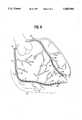
- FIG. 8is a schematic view of a patient's coronary arteries with one intravascular device as shown in FIG. 1 disposed within the right coronary artery and another disposed in the anterior interventricular branch of the left coronary artery.
- FIGS. 1-5schematically illustrate an embodiment of the invention wherein the elongated intravascular device 10 includes shaft 11 with a distal section 12 and a proximal section 13.
- the shaft 11has a braided tubular member 14 formed of a plurality of electrical conductors 15.
- the distal section 12 of the shaft 11is provided with a plurality of sensing electrodes 16 which are arranged in a first array 17 of sensing electrodes with a relatively small interelectrode spacing 19 and a second array 20 of sensing electrodes with a second interelectrode spacing 21 which is much greater than the first interelectrode spacing. Every other sensing electrode 16 within the first array 17 may be common to the second array 20.
- a core member 22is disposed within the inner lumen of the braided tubular member 14 and extends beyond the distal end thereof.
- a distal guide tip 23includes a helical coil 24 disposed about and secured by suitable means, such as brazing, soldering or welding, to the distal extremity of the core member 22 and is provided with a smooth rounded distal end 25 formed by joining the distal tip of the coil 24 to the distal extremity of the core member 22.
- the distal extremity of the core member 22is preferably flattened into a rectangular transverse cross section.
- An alternative "floppy" constructionmay be used where the distal extremity of the core member 22 terminates short of the distal end of the intravascular device and a shaping ribbon extends from the distal end of the core member 22 to the smooth rounded distal end 25.
- FIG. 2illustrates braided tubular member 14 with a single layer of braided strands. All of the strands in the layers need not be conductors 15, some may be formed of polymer materials such as nylon or Kevlar®. A plurality of braided layers may be employed, if needed, depending upon the number of sensing electrodes 16.
- proximal section 13 of the shaft 11 as shown in FIG. 1has two extensions 26 and 27 which have multi-pin connectors 28 and 29 the proximal ends thereof with each of the electrical conductors forming the braided tubular member 14 being electrically connected to a separate pin. Details of proximal extension 26 is depicted in FIG. 5 which includes pin connector 28.
- FIGS. 6 and 7schematically illustrate another presently preferred embodiment of the invention in the form of a catheter 30 with a catheter shaft 31 having an inner lumen 32 defined by an inner tubular element or lining 33, preferably formed of lubricous material such as Teflon® or other fluoropolymer.
- a braided tubular member 34is disposed about tubular lining 33 and is formed of a plurality of individually insulated electrical conductors 35 which are electrically connected to individual sensing electrodes 36 as in the previously described embodiment. Some of the strands in the braided layers may be formed of other materials such as nylon.
- the sensing electrodes 36are arranged in a compact array 37 with an interelectrode spacing of less than 2 mm, preferably less than about 1.5 mm.
- An outer polymer jacket 38extends the length of the shaft 31 and the portion of the jacket extending beyond the distal end of the braided tubular member 34 is tapered to provide a nontraumatic flexible distal tip 38.
- the outer jacket 37overlaps the leading and trailing edges of the electrodes 36 to avoid exposing a sharp metal edge when advancing or withdrawing the catheter through a patient's blood vessel.
- the catheter 30may be used to detect electrical activity from within the patient's coronary veins or arteries and then be used to direct fluids containing cardioplegic materials such as iced saline, solutions of KCl, lidocaine, procaineamide hydrochloride and the like to areas of the patient's heart which are suspected to be the origin of or to conduct aberrant signals causing arrhythmia. If the arrhythmia stops upon the delivery of a cardioplegic agent, then the operator is reasonably assured that the artery or vein through which the cardioplegic agent is delivered leads toward (in the case of an artery) or away from (in the case of a vein) the region of the patient's heart which is to be ablated in order to terminate the arrhythmia.
- cardioplegic materialssuch as iced saline, solutions of KCl, lidocaine, procaineamide hydrochloride and the like
- the signal reception by the electrodes 36are essentially the same as the signal reception for the first array in the previously described embodiment shown in FIG. 1-5.
- the catheter 30may be used in conjunction with a conventional guidewire or an intravascular device 10 as illustrated in FIGS. 1-5 where the guidewire or intravascular device is slidably disposed within the inner lumen 32 of the catheter. Adjustments in the relative locations of the intravascular device 10 and catheter 30 can be easily made by moving the intravascular device through the inner lumen 32 of the catheter 30 or moving the catheter over the guidewire or both.
- a guiding catheterWhen using a femoral artery or femoral vein approach to the patient's heart, it is frequently helpful to utilize a guiding catheter to guide the catheter or guidewire of the invention to the coronary artery ostium or the coronary sinus ostium as is done in other interventional coronary procedures, such as angioplasty.
- guiding cathetershave specially shaped distal tips to facilitate the seating thereof within the desired ostium, thus eliminating the trouble of directing a catheter or guidewire of the invention into the desire ostium.
- the sensing electrodesare typically gold bands with widths of about 0.25 to about 1 mm, typically about 0.5 mm, the longitudinal dimension when mounted on the intravascular device, which is just large enough to be fluoroscopically visible.
- the overall length of the intravascular devices of the inventionmay range from about 80 to about 300 cm, typically about 120 to about 175 cm for delivery through the femoral artery or vein and about 90 to about 135 cm for delivery through the brachiocephalic artery or internal jugular vein. If the guidewire is to be advanced through the inner lumen of the catheter it should be longer than the catheter by about 20 to about 40 cm.
- the distal section of the catheteris about 3 to about 50 cm in length and is configured to be readily advanceable through a patient's coronary arteries or cardiac veins.
- the outer diameter of the cathetershould be less than about 0.065 inch (1.7 mm) and preferably about 0.058 inch (4 Fr; 1.5 mm).
- the inner lumen 32is about 0.012 to about 0.045 inch (0.3-1.1 mm) in diameter to facilitate the reception and advancement of a guidewire therethrough.
- the distal section of the guidewireis about 15 to about 40 cm in length and about 0.008 to about 0.022 inch (0.2-0.56 mm) in outer diameter to facilitate advancement through the coronary arteries and cardiac veins of a human being having natural diameters of less than 0.05 inch (1.27 mm), preferably less than 0.03 inch (0.76 mm).
- the distal guide tip on the guidewireis about 2 to about 10 cm in length and the coil is formed of wire about 0.0003 to about 0.006 inch (0.008-0.153 mm) in diameter.
- the core member of the guidewiremay be tapered along its distal section as in conventional guidewire construction.
- the flattened distal extremity of the core memberhas a rectangular transverse cross section of about 0.002 by 0.006 inch (0.051-0.15 mm).
- the materials of construction of the various guidewire and catheter partsmay be formed of conventional materials.
- the electrical conductorsmay be electrical grade copper wire about 0.005 inch (0.13 mm) in diameter which are provided with a thin insulated jacket or coating of polyimide or other suitable insulator.
- the outer jacketmay be a thermoplastic fluoropolymer such as THV which is available from the 3M Corporation.
- the distal tip coil on the guidewire form of the inventionis preferably formed of platinum to facilitate fluoroscopic observation thereof within the patient, but it may be formed in whole or in part with other material such as stainless steel, titanium, palladium, niobium, iridium and alloys thereof.
- the core wire of the guidewiremay be formed of stainless steel or a superelastic NiTi type alloy, with the latter preferably having a stable austenite phase at body temperature and exhibiting a stress induced austenite-to-martensite phase transformation.
- Proximal and distal sections of the core membermay be formed of different materials so as to provide a stronger proximal section for greater pushability and a more flexible distal section to facilitate passage through tortuous coronary anatomy.
- FIG. 8One presently preferred method of using the elongated intravascular devices of the invention as shown in FIG. 8 wherein the distal portion 11 of the guidewires 10 such as shown in FIG. 1 are disposed within the right coronary artery and the anterior interventricular branch of the left coronary artery.
- the electrodes 16 on the distal portion 11extend along a major portion of the arteries in a first electrode array 17 where the interelectrode spacing is relatively small and a second electrode array 20 where the interelectrode spacing is greater than in the first array.
- alternate electrodes in the first array 17may be electrodes in the second array 20.
- the individual intravascular devices 10may be moved within the arteries as needed to optimize the signals received by the electrodes 16.
- Signals from the electrodes 16 in the second array 20are used to first detect the general region of the patient's heart from which the signals of interest originate.
- the intravascular device 10may then repositioned to the extent necessary to place the first electrode array 17 as close as possible to the region of interest.
- the electrical activity from the desired regionis then sensed by the electrodes 16 of the first array to more accurately locate the arrhythmogenic site.
- the detection of electrical activity by the intravascular devices 10 within both the right coronary artery and the anterior interventricular branch of the left coronary arterymay be coordinated so that the region of interest can be located with the second electrode array of each device and then more accurately pinpointed by use of the first electrode array in both devices or the device closest to the region.
- the distal guide tip 23may be shaped to facilitate entry into a side branch of the coronary artery.
- the intravascular sensing devicebe introduced into a femoral artery or a femoral vein (or other convenient body access site) and be advanced through the patient's vasculature to the coronary veins or arteries. Once the intravascular device is situated in a proper location in the coronary vasculature, electrical activity may be received in any way that is appropriate for the specific situation. The catheter or guidewire may be moved to another location and another set of signals received.
- each electrode mounted on the distal section of the sensing deviceis individually brought out via the woven wires or filaments to the electrical connection at the proximal end, that each electrode may be used in conjunction with any other electrode in a bipolar mode or they may be used in a monopolar mode.
- the sensing devicesmay be used in multiples, e.g., a sensing device in each of the major coronary veins and arteries, as shown in FIG. 8, to provide an overall and complete electrical map of the heart. In this way, arrhythmic foci may be readily located and therapeutic action taken.
Landscapes
- Health & Medical Sciences (AREA)
- Life Sciences & Earth Sciences (AREA)
- Surgery (AREA)
- Public Health (AREA)
- Veterinary Medicine (AREA)
- General Health & Medical Sciences (AREA)
- Animal Behavior & Ethology (AREA)
- Engineering & Computer Science (AREA)
- Biomedical Technology (AREA)
- Heart & Thoracic Surgery (AREA)
- Medical Informatics (AREA)
- Molecular Biology (AREA)
- Cardiology (AREA)
- Pathology (AREA)
- Biophysics (AREA)
- Physiology (AREA)
- Physics & Mathematics (AREA)
- Reproductive Health (AREA)
- Vascular Medicine (AREA)
- Nuclear Medicine, Radiotherapy & Molecular Imaging (AREA)
- Measurement And Recording Of Electrical Phenomena And Electrical Characteristics Of The Living Body (AREA)
- Surgical Instruments (AREA)
- Measuring Pulse, Heart Rate, Blood Pressure Or Blood Flow (AREA)
Abstract
Description
This application is a divisional application of application Ser. No. 08/443,657, filed on May 18, 1995, which is a continuation-in-part of application Ser. No. 08/188,619, filed on Jan. 27, 1994, now U.S. Pat. No. 5,509,411, which is a continuation-in-part of application Ser. No. 08/057,294, filed on May 5, 1993, now abandoned, which is a continuation-in-part of application Ser. No. 08/043,449 filed on Apr. 5, 1993, now abandoned, continuation-in-part of application Ser. No. 08/010,818, filed on Jan. 29, 1993, now abandoned.
This invention generally relates to a system for detecting electrical activity or signals of a patient's heart from within blood vessels thereof and particularly for determining the source of heart signals causing arrhythmia.
Prior methods for treating a patient's arrhythmia include the use of antiarrhythmic drugs such as sodium and calcium channel blockers or drugs which reduce the Beta-adrenergic activity. Other methods include the surgically sectioning the origin of the signals causing the arrhythmia or the conducting pathway for such signals. More frequently, however, the heart tissue which causes the arrhythmia is destroyed by heat, e.g. applying a laser beam or high frequency electrical energy, e.g RF or microwave, to a desired location on the patient's endocardium, in order to terminate the arrhythmia.
In the latter instance, the location of the tissue site causing or involved with the arrhythmia must be accurately known in order to be able to contact the desired location with a tissue destroying device. A major problem of ablating the site of the origin of the signals or a conductive pathway is to accurately determine the site so that an excessive amount of good tissue is not destroyed along with the arrhythmogenic site while ensuring that the arrhythmia does not return. For example, the average arrhythmogenic site consists of an area of about 1.4 cm2 of endocardial tissue, whereas a re-entrant site might be much larger. RF ablation techniques produce lesions about 0.5 cm2 in area, so several lesions may be necessary to completely ablate an area of interest. If the arrhythmogenic or re-entrant site is not accurately mapped, much good tissue surrounding the site will be unnecessarily destroyed.
A variety of methods have been used to detect electrical activity within a patient's heart to facilitate the mapping of electrical activity causing the arrhythmia. A number of U.S. Patents describe the use of elongated intravascular signal sensing devices which are advanced through the patient's vasculature until the distal portions of the sensing devices are disposed within one or more of the patient's heart chambers with one or more electrodes on the distal portion of the device in contact with the endocardial lining. While this procedure is widely used, it does not always allow the site of arrhythmogenic signals to be accurately determined.
The literature also mentions advancing an intravascular signal sensing device within a patient's coronary artery or coronary sinus or a cardiac vein. However, these methods appear to be experimental and have not been widely used clinically.
What has been needed is a method and system for accurately detecting the source of signals which cause the arrhythmia.
This invention is directed to an elongated intravascular sensing device for detecting electrical activity from within a lumen of a patients body. The device is suitable for detecting electrical activity from within a patient's vein or artery, such as electrical activity causing arrhythmia.
The intravascular sensing device of the invention comprises an elongated shaft with a proximal section and a distal section, with the distal section of the shaft being configured to be more flexible than the proximal section so as to be advanceable through tortuous anatomy, such as the patient's coronary arteries or cardiac veins. The device may also be used in other portions of the patient's body to locate electrical activity which may be involved with other conditions.
The flexible distal section of the sensing device is provided with a first array of sensing electrodes, e.g up to 16 or more electrodes, which may be bipolar electrodes for multipolar mode detection or independent electrodes for monopolar mode detection, which have a relatively small interelectrode spacing. In accordance with one aspect of the present invention, the electrodes in the first array have an interelectrode spacing which ranges from about 0.25 to about 2 mm, preferably about 0.5 to about 1.5 mm. The distal section may have a second array of sensing electrodes with an interelectrode spacing greater than the interelectrode spacing in the first array and generally about 2 to about 10 mm, preferably about 3 to about 8 mm. Alternate electrodes in the first array may be part of the second array of electrodes. The electrode spacing within an array of electrodes may vary, for example, the spacing at the extremities of the array may be larger than the spacing at the center of the array. However, for ease in analyzing the signals received from the sensing electrodes, it is preferred that the interelectrode spacing be uniform within an array. Both the spacing between electrode pairs and the spacing between the electrodes of the electrode pairs may be varied. The second array of sensing electrodes may be used to determine the general location of sensed electrical activity, such as an arrhythmogenic site, and the first array is then utilized to more accurately pinpoint the area of interest. When the general location of the electrical activity is already known, only the compact array of sensing electrodes needs to be used. When a bipolar or multipolar mode of sensing is to be used, the spacing between the electrodes of a pair of bipolar electrodes may be much less than the spacing between pairs of bipolar electrodes.
The shaft of the intravascular sensing device is preferably formed of a plurality of individually insulated electrical conductors braided or wound into an elongated tubular member with an inner lumen extending therein. However, not all of the braided strands which make up the tubular member need be electrical conductors. Some may be high strength fibers such as nylon, Kevlar® and the like. The insulation on individual electrical conductors is exposed under each of the sensing electrodes to facilitate an electrical connection with the electrode. The electrical connection between the electrical conductor and the electrode may be secured by means of a suitable solder or brazing material, and the electrodes may be further secured to the underlying tubular member by a suitable adhesive to ensure maintenance of electrical contact with the exposed conductors.
The sensing electrodes may be circular bands about 0.25 to about 1 mm in width (the longitudinal dimension when on the device) and are preferably made from conducting material which is biocompatible with the body fluids such as gold.
A plastic jacket, preferably a lubricous polymer such as a thermoplastic fluoropolymer, is applied to the length of the braided tubular member with a slight overlap of the jacket over the edges of the individual electrodes to prevent exposure of a sharp metallic edge of the electrode which can cause damage to a blood vessel wall when the elongated device is advanced through a blood vessel. The entire circumference of an electrode need not be exposed. For example, the plastic jacket may be disposed about the distal shaft section on which the electrodes are mounted and holes may be made in the jacket to expose small portions of the underlying electrodes. The proximal ends of the electrical conductors are electrically connected to individual pins of a multi-pin connector on the proximal end of the shaft which is configured to be connected to a receiving member in electrical communication with a display unit which can display representations of the electrical activity sensed.
The elongated device of the invention may be in the form of a guidewire which has an elongated core member disposed within an inner lumen of the tubular member formed by the braided electrical conductors. The distal section of the guidewire may have a flexible guide tip which is distal to the length on which the sensing electrodes are mounted. The distal guide tip may have a helical coil which is disposed about the distal extremity of the core member or a separate shaping member, e.g. a ribbon, which extends from the distal extremity of the core member. The distal end of the core member or the separate shaping member may be manually shaped by the physician to facilitate steering the elongated sensing device within the patients vasculature by torquing the proximal end which extends out of the patient during the procedure. A smooth rounded tip or plug is provided at the distal end of the coil to avoid damage to a blood vessel when being advanced through the patient's vascular system. Conventional guidewire construction may be employed.
The elongated device of the invention may also be in the form of a catheter which has an elongated inner lumen extending from the proximal end to a discharge or guidewire port in the distal end of the device. The distal end of the catheter may be provided with a soft tip to minimize traumatic engagement with a blood vessel wall when being advanced therein. In one presently preferred embodiment, the inner lumen of the catheter form of the device is configured to allow the passage therethrough of a conventional guidewire or a guidewire version of the device of the invention which allows signal detection at different locations within the same blood vessel or branch thereof such as described in copending application Ser. No. 08/188,298, filed on Jan. 27, 1994, which is incorporated herein in its entirety.
When using the intravascular device of the invention, it is first introduced percutaneously by a conventional Seldinger technique or by means of a cut-down into a major peripheral artery or vein (e.g. the femoral vein or the femoral artery) and advanced through the vasculature to one or more desired locations within the veins or arteries of the patient's heart. The distal section of the elongated device of the invention is configured to be advanceable within blood vessels having a native inner diameter of less than about one millimeter and preferably less than 0.75 mm. A plurality of such elongated devices may be introduced into the patient's vascular system with an elongated device within one or more of the patient's cardiac veins and an elongated device within one or more of the patient's coronary arteries. The general location of the electrical activity may be first detected by means of the second electrode array having relatively large interelectrode spacing and the general location of the electrical activity is first determined. The electrical activity may then be detected by the electrodes of the first array which allows a much more accurate location of the site of the electrical activity.
With the device of the invention, electrical signals from the patient's heart are received by the plurality of sensing electrodes on the distal section and transmitted through electrical conductors attached to the individual electrodes to multipin connectors on the proximal ends of the shaft. The position of an elongated sensing device of the invention within an artery or vein of the patient's heart may be adjusted to optimize signal reception by the electrodes in the second array to roughly detect the location of the desired electrical activity and then the position may again be adjusted to provide a high definition signal reception by the more closely spaced electrodes in the first array. In this manner the location of the electrical activity may be pinpointed with much greater accuracy. The high resolution signal detection provided by the multiple array electrode system greatly facilitates the detection of electrical activity from arrhythmogenic sites or conducting pathways and the mapping thereof to detect the locations of such activity.
The elongated device of the invention provides substantially improved reception of electrical activity within the patient's heart without interference from electrical activity from other regions of the patient's heart. These and other advantages of the invention will become more apparent from the following detailed description of the invention and the accompanying exemplary drawings.
FIG. 1 is an elevational view of an intravascular device having features of the invention.
FIG. 2 is an enlarged longitudinal cross-sectional view of a distal portion of the intravascular device shown in FIG. 1.
FIG. 3 is an enlarged transverse cross-sectional view of the distal portion of the intravascular device shown in FIG. 1 taken along the lines 3--3.
FIG. 4 is a longitudinal cross-sectional view of an intermediate portion of the intravascular device shown in FIG. 1 taken along the lines 4--4.
FIG. 5 is a longitudinal cross-sectional view of an extension of the proximal extremity of the intravascular device shown in FIG. 1 taken along the lines 6--6.
FIG. 6 is an elevational view, partially in section, of an alternative embodiment of the invention in the form of a catheter with a guidewire device disposed within the inner lumen of the catheter.
FIG. 7 is a transverse cross-sectional view of the catheter shown in FIG. 6 taken along the lines 7--7.
FIG. 8 is a schematic view of a patient's coronary arteries with one intravascular device as shown in FIG. 1 disposed within the right coronary artery and another disposed in the anterior interventricular branch of the left coronary artery.
Reference is made to FIGS. 1-5 which schematically illustrate an embodiment of the invention wherein the elongatedintravascular device 10 includesshaft 11 with adistal section 12 and a proximal section 13. Theshaft 11 has a braidedtubular member 14 formed of a plurality ofelectrical conductors 15. Thedistal section 12 of theshaft 11 is provided with a plurality ofsensing electrodes 16 which are arranged in afirst array 17 of sensing electrodes with a relatively smallinterelectrode spacing 19 and asecond array 20 of sensing electrodes with a second interelectrode spacing 21 which is much greater than the first interelectrode spacing. Everyother sensing electrode 16 within thefirst array 17 may be common to thesecond array 20. Acore member 22 is disposed within the inner lumen of the braidedtubular member 14 and extends beyond the distal end thereof. Adistal guide tip 23 includes ahelical coil 24 disposed about and secured by suitable means, such as brazing, soldering or welding, to the distal extremity of thecore member 22 and is provided with a smooth rounded distal end 25 formed by joining the distal tip of thecoil 24 to the distal extremity of thecore member 22. The distal extremity of thecore member 22 is preferably flattened into a rectangular transverse cross section. An alternative "floppy" construction may be used where the distal extremity of thecore member 22 terminates short of the distal end of the intravascular device and a shaping ribbon extends from the distal end of thecore member 22 to the smooth rounded distal end 25.
FIG. 2 illustrates braidedtubular member 14 with a single layer of braided strands. All of the strands in the layers need not beconductors 15, some may be formed of polymer materials such as nylon or Kevlar®. A plurality of braided layers may be employed, if needed, depending upon the number ofsensing electrodes 16.
The proximal section 13 of theshaft 11 as shown in FIG. 1 has twoextensions multi-pin connectors tubular member 14 being electrically connected to a separate pin. Details ofproximal extension 26 is depicted in FIG. 5 which includespin connector 28.
FIGS. 6 and 7 schematically illustrate another presently preferred embodiment of the invention in the form of acatheter 30 with acatheter shaft 31 having aninner lumen 32 defined by an inner tubular element or lining 33, preferably formed of lubricous material such as Teflon® or other fluoropolymer. A braidedtubular member 34 is disposed abouttubular lining 33 and is formed of a plurality of individually insulatedelectrical conductors 35 which are electrically connected toindividual sensing electrodes 36 as in the previously described embodiment. Some of the strands in the braided layers may be formed of other materials such as nylon. Thesensing electrodes 36 are arranged in acompact array 37 with an interelectrode spacing of less than 2 mm, preferably less than about 1.5 mm. Anouter polymer jacket 38 extends the length of theshaft 31 and the portion of the jacket extending beyond the distal end of the braidedtubular member 34 is tapered to provide a nontraumatic flexibledistal tip 38. As in the previously described example, theouter jacket 37 overlaps the leading and trailing edges of theelectrodes 36 to avoid exposing a sharp metal edge when advancing or withdrawing the catheter through a patient's blood vessel.
Thecatheter 30 may be used to detect electrical activity from within the patient's coronary veins or arteries and then be used to direct fluids containing cardioplegic materials such as iced saline, solutions of KCl, lidocaine, procaineamide hydrochloride and the like to areas of the patient's heart which are suspected to be the origin of or to conduct aberrant signals causing arrhythmia. If the arrhythmia stops upon the delivery of a cardioplegic agent, then the operator is reasonably assured that the artery or vein through which the cardioplegic agent is delivered leads toward (in the case of an artery) or away from (in the case of a vein) the region of the patient's heart which is to be ablated in order to terminate the arrhythmia. The signal reception by theelectrodes 36 are essentially the same as the signal reception for the first array in the previously described embodiment shown in FIG. 1-5. Once the tissue causing the problem is located, high frequency electrical energy is emitted from the emittingelectrode 17 to form a lesion in the tissue adjacent to the blood vessel and to thereby terminate the aberrant electrical activity.
Thecatheter 30 may be used in conjunction with a conventional guidewire or anintravascular device 10 as illustrated in FIGS. 1-5 where the guidewire or intravascular device is slidably disposed within theinner lumen 32 of the catheter. Adjustments in the relative locations of theintravascular device 10 andcatheter 30 can be easily made by moving the intravascular device through theinner lumen 32 of thecatheter 30 or moving the catheter over the guidewire or both.
When using a femoral artery or femoral vein approach to the patient's heart, it is frequently helpful to utilize a guiding catheter to guide the catheter or guidewire of the invention to the coronary artery ostium or the coronary sinus ostium as is done in other interventional coronary procedures, such as angioplasty. Typically, guiding catheters have specially shaped distal tips to facilitate the seating thereof within the desired ostium, thus eliminating the trouble of directing a catheter or guidewire of the invention into the desire ostium.
The sensing electrodes are typically gold bands with widths of about 0.25 to about 1 mm, typically about 0.5 mm, the longitudinal dimension when mounted on the intravascular device, which is just large enough to be fluoroscopically visible.
The overall length of the intravascular devices of the invention may range from about 80 to about 300 cm, typically about 120 to about 175 cm for delivery through the femoral artery or vein and about 90 to about 135 cm for delivery through the brachiocephalic artery or internal jugular vein. If the guidewire is to be advanced through the inner lumen of the catheter it should be longer than the catheter by about 20 to about 40 cm. The distal section of the catheter is about 3 to about 50 cm in length and is configured to be readily advanceable through a patient's coronary arteries or cardiac veins. The outer diameter of the catheter should be less than about 0.065 inch (1.7 mm) and preferably about 0.058 inch (4 Fr; 1.5 mm). Theinner lumen 32 is about 0.012 to about 0.045 inch (0.3-1.1 mm) in diameter to facilitate the reception and advancement of a guidewire therethrough. The distal section of the guidewire is about 15 to about 40 cm in length and about 0.008 to about 0.022 inch (0.2-0.56 mm) in outer diameter to facilitate advancement through the coronary arteries and cardiac veins of a human being having natural diameters of less than 0.05 inch (1.27 mm), preferably less than 0.03 inch (0.76 mm). The distal guide tip on the guidewire is about 2 to about 10 cm in length and the coil is formed of wire about 0.0003 to about 0.006 inch (0.008-0.153 mm) in diameter. The core member of the guidewire may be tapered along its distal section as in conventional guidewire construction. The flattened distal extremity of the core member has a rectangular transverse cross section of about 0.002 by 0.006 inch (0.051-0.15 mm).
To the extent not previously described, the materials of construction of the various guidewire and catheter parts may be formed of conventional materials. The electrical conductors may be electrical grade copper wire about 0.005 inch (0.13 mm) in diameter which are provided with a thin insulated jacket or coating of polyimide or other suitable insulator. The outer jacket may be a thermoplastic fluoropolymer such as THV which is available from the 3M Corporation. The distal tip coil on the guidewire form of the invention is preferably formed of platinum to facilitate fluoroscopic observation thereof within the patient, but it may be formed in whole or in part with other material such as stainless steel, titanium, palladium, niobium, iridium and alloys thereof. The core wire of the guidewire may be formed of stainless steel or a superelastic NiTi type alloy, with the latter preferably having a stable austenite phase at body temperature and exhibiting a stress induced austenite-to-martensite phase transformation. Proximal and distal sections of the core member may be formed of different materials so as to provide a stronger proximal section for greater pushability and a more flexible distal section to facilitate passage through tortuous coronary anatomy.
One presently preferred method of using the elongated intravascular devices of the invention as shown in FIG. 8 wherein thedistal portion 11 of theguidewires 10 such as shown in FIG. 1 are disposed within the right coronary artery and the anterior interventricular branch of the left coronary artery. As indicated, theelectrodes 16 on thedistal portion 11 extend along a major portion of the arteries in afirst electrode array 17 where the interelectrode spacing is relatively small and asecond electrode array 20 where the interelectrode spacing is greater than in the first array. As previously described alternate electrodes in thefirst array 17 may be electrodes in thesecond array 20. The individualintravascular devices 10 may be moved within the arteries as needed to optimize the signals received by theelectrodes 16. Signals from theelectrodes 16 in thesecond array 20 are used to first detect the general region of the patient's heart from which the signals of interest originate. Theintravascular device 10 may then repositioned to the extent necessary to place thefirst electrode array 17 as close as possible to the region of interest. The electrical activity from the desired region is then sensed by theelectrodes 16 of the first array to more accurately locate the arrhythmogenic site. The detection of electrical activity by theintravascular devices 10 within both the right coronary artery and the anterior interventricular branch of the left coronary artery may be coordinated so that the region of interest can be located with the second electrode array of each device and then more accurately pinpointed by use of the first electrode array in both devices or the device closest to the region. While not shown in the drawings, thedistal guide tip 23 may be shaped to facilitate entry into a side branch of the coronary artery.
It is within the ambit of this invention that the intravascular sensing device be introduced into a femoral artery or a femoral vein (or other convenient body access site) and be advanced through the patient's vasculature to the coronary veins or arteries. Once the intravascular device is situated in a proper location in the coronary vasculature, electrical activity may be received in any way that is appropriate for the specific situation. The catheter or guidewire may be moved to another location and another set of signals received. It should be apparent that since each electrode mounted on the distal section of the sensing device is individually brought out via the woven wires or filaments to the electrical connection at the proximal end, that each electrode may be used in conjunction with any other electrode in a bipolar mode or they may be used in a monopolar mode. The sensing devices may be used in multiples, e.g., a sensing device in each of the major coronary veins and arteries, as shown in FIG. 8, to provide an overall and complete electrical map of the heart. In this way, arrhythmic foci may be readily located and therapeutic action taken.
Although individual features of one embodiment of the invention may be described herein and shown in one or more of the drawings and not in others, those skilled in the art will recognize that individual features of one embodiment of the invention can be combined with any or all the features of another embodiment of the invention. Additionally, various modifications and improvements may be made to the invention without departing from the scope thereof.
Claims (3)
1. A method of detecting electrical activity of a patient's heart from within a blood vessel thereof, comprising:
a) introducing into a patient's vasculature an intravascular catheter which has
an elongated catheter shaft having proximal and distal ends, a first array of sensing electrodes on a distal section having a relatively small interelectrode spacing and a second array of sensing electrodes on the distal section with an interelectrode spacing which is larger than the interelectrode spacing in the first array, and means to transmit electrical activity sensed by the individual electrodes in the first array and the second array to electrical connector means on a proximal extremity of the shaft;
b) advancing the catheter within the patient's vasculature until the distal section of such catheter is disposed within a first coronary artery or cardiac vein of the patient's heart;
c) detecting electrical activity of the patient's heart from within the cardiac vein or the coronary artery by means of the electrodes in the second array of sensing electrodes to detect a general region within the patient's heart where the electrical activity is located; and
d) detecting electrical activity of the patient's heart from within the cardiac vein or the coronary artery by means of the sensing electrodes in the first array of sensing electrodes to more accurately detect the location within the patient's heart of the electrical activity.
2. The method of claim 1 wherein electrical activity of the patient's heart is detected in a bipolar mode.
3. The method of claim 2 including:
a) introducing into the patient's vasculature a second intravascular catheter which has
an elongated catheter shaft having proximal and distal ends, a first array of sensing electrodes longitudinally disposed on a distal section having a minimum interelectrode spacing and a second array of sensing electrodes longitudinally disposed on the distal section having a minimum interelectrode spacing which is greater than the minimum interelectrode spacing in the first array, and means to transmit electrical activity sensed by the individual electrodes in the first array and the second array to electrical connector means on a proximal extremity of the shaft to facilitate transmission of the electrical activity sensed by the electrodes;
b) advancing the second intravascular catheter within the patient's vasculature until the distal section of such catheter is disposed within a second coronary artery or cardiac vein of the patient's heart;
c) detecting electrical activity of the patient's heart from within the second blood vessel by means of the electrodes in the second array of sensing electrodes to detect the general region within the patient's heart from which the electrical activity arose; and
d) detecting electrical activity of the patient's heart from within the second blood vessel by means of the sensing electrodes in the first array of sensing electrodes to more accurately detect the location within the patient's heart from which the electrical activity arose.
Priority Applications (2)
| Application Number | Priority Date | Filing Date | Title |
|---|---|---|---|
| US08/484,202US5645064A (en) | 1992-01-29 | 1995-06-07 | High resolution intravascular signal detection |
| US08/805,901US5711298A (en) | 1994-01-27 | 1997-02-24 | High resolution intravascular signal detection |
Applications Claiming Priority (6)
| Application Number | Priority Date | Filing Date | Title |
|---|---|---|---|
| US1081892A | 1992-01-29 | 1992-01-29 | |
| US4344993A | 1993-04-05 | 1993-04-05 | |
| US5729493A | 1993-05-05 | 1993-05-05 | |
| US08/188,619US5509411A (en) | 1993-01-29 | 1994-01-27 | Intravascular sensing device |
| US08/443,657US5699796A (en) | 1993-01-29 | 1995-05-18 | High resolution intravascular signal detection |
| US08/484,202US5645064A (en) | 1992-01-29 | 1995-06-07 | High resolution intravascular signal detection |
Related Parent Applications (1)
| Application Number | Title | Priority Date | Filing Date |
|---|---|---|---|
| US08/443,657DivisionUS5699796A (en) | 1992-01-29 | 1995-05-18 | High resolution intravascular signal detection |
Related Child Applications (1)
| Application Number | Title | Priority Date | Filing Date |
|---|---|---|---|
| US08/805,901ContinuationUS5711298A (en) | 1994-01-27 | 1997-02-24 | High resolution intravascular signal detection |
Publications (1)
| Publication Number | Publication Date |
|---|---|
| US5645064Atrue US5645064A (en) | 1997-07-08 |
Family
ID=23761682
Family Applications (4)
| Application Number | Title | Priority Date | Filing Date |
|---|---|---|---|
| US08/443,657Expired - LifetimeUS5699796A (en) | 1992-01-29 | 1995-05-18 | High resolution intravascular signal detection |
| US08/484,202Expired - LifetimeUS5645064A (en) | 1992-01-29 | 1995-06-07 | High resolution intravascular signal detection |
| US08/488,132Expired - LifetimeUS5957842A (en) | 1994-01-27 | 1995-06-07 | High resolution intravascular signal detection |
| US08/805,901Expired - LifetimeUS5711298A (en) | 1994-01-27 | 1997-02-24 | High resolution intravascular signal detection |
Family Applications Before (1)
| Application Number | Title | Priority Date | Filing Date |
|---|---|---|---|
| US08/443,657Expired - LifetimeUS5699796A (en) | 1992-01-29 | 1995-05-18 | High resolution intravascular signal detection |
Family Applications After (2)
| Application Number | Title | Priority Date | Filing Date |
|---|---|---|---|
| US08/488,132Expired - LifetimeUS5957842A (en) | 1994-01-27 | 1995-06-07 | High resolution intravascular signal detection |
| US08/805,901Expired - LifetimeUS5711298A (en) | 1994-01-27 | 1997-02-24 | High resolution intravascular signal detection |
Country Status (5)
| Country | Link |
|---|---|
| US (4) | US5699796A (en) |
| EP (1) | EP0825829A1 (en) |
| JP (1) | JP3785190B2 (en) |
| CA (1) | CA2221620A1 (en) |
| WO (1) | WO1996036277A1 (en) |
Cited By (30)
| Publication number | Priority date | Publication date | Assignee | Title |
|---|---|---|---|---|
| WO1998006451A1 (en) | 1996-08-15 | 1998-02-19 | Cardima, Inc. | Intraluminal delivery of tissue lysing medium |
| WO1998032375A1 (en)* | 1997-01-24 | 1998-07-30 | Cardiac Pacemakers, Inc. | Side access 'over the wire' pacing lead |
| US5895355A (en)* | 1995-05-23 | 1999-04-20 | Cardima, Inc. | Over-the-wire EP catheter |
| US6002956A (en)* | 1995-05-23 | 1999-12-14 | Cardima, Inc. | Method of treating using an over-the-wire EP catheter |
| US6241665B1 (en) | 1998-10-21 | 2001-06-05 | Plc Medical System, Inc. | Percutaneous mapping system |
| EP1120088A1 (en)* | 2000-01-28 | 2001-08-01 | William Cook Europe ApS | An embolization device introducer |
| WO2001072368A2 (en) | 2000-03-31 | 2001-10-04 | Medtronic, Inc. | Intralumenal visualization system with deflectable mechanism |
| US6348041B1 (en) | 1999-03-29 | 2002-02-19 | Cook Incorporated | Guidewire |
| US6383146B1 (en) | 1999-03-29 | 2002-05-07 | Cook Incorporated | Guidewire |
| US20020173785A1 (en)* | 2000-03-31 | 2002-11-21 | Medtronic, Inc. | System and method for positioning implantable medical devices within coronary veins |
| US6589227B2 (en) | 2000-01-28 | 2003-07-08 | William Cook Europe Aps | Endovascular medical device with plurality of wires |
| WO2003090833A1 (en) | 2002-04-25 | 2003-11-06 | Medtronic, Inc. | Method and system for delivery of a medical electrical lead within a venous system |
| US20040082947A1 (en)* | 2002-10-25 | 2004-04-29 | The Regents Of The University Of Michigan | Ablation catheters |
| US20040082879A1 (en)* | 2000-01-28 | 2004-04-29 | Klint Henrik S. | Endovascular medical device with plurality of wires |
| US6733500B2 (en) | 2000-03-31 | 2004-05-11 | Medtronic, Inc. | Method and system for delivering a medical electrical lead within a venous system |
| US20060100602A1 (en)* | 2001-01-26 | 2006-05-11 | William Cook Europe Aps | Endovascular medical device with plurality of wires |
| US20070083193A1 (en)* | 2005-08-22 | 2007-04-12 | Werneth Randell L | User interface for tissue ablation system |
| US20080161803A1 (en)* | 2002-10-25 | 2008-07-03 | The Regents Of The University Of Michigan | Ablation Catheters And Methods For Their Use |
| US7429261B2 (en) | 2004-11-24 | 2008-09-30 | Ablation Frontiers, Inc. | Atrial ablation catheter and method of use |
| US20080275443A1 (en)* | 2004-11-24 | 2008-11-06 | Hakan Oral | Atrial ablation catheter adapted for treatment of septal wall arrhythmogenic foci and method of use |
| US20100249654A1 (en)* | 2007-09-18 | 2010-09-30 | Cook Incorporated | Wire guide |
| US7850685B2 (en) | 2005-06-20 | 2010-12-14 | Medtronic Ablation Frontiers Llc | Ablation catheter |
| US8486063B2 (en) | 2004-10-14 | 2013-07-16 | Medtronic Ablation Frontiers Llc | Ablation catheter |
| US8517923B2 (en)* | 2000-04-03 | 2013-08-27 | Intuitive Surgical Operations, Inc. | Apparatus and methods for facilitating treatment of tissue via improved delivery of energy based and non-energy based modalities |
| US8617152B2 (en) | 2004-11-15 | 2013-12-31 | Medtronic Ablation Frontiers Llc | Ablation system with feedback |
| US8641704B2 (en) | 2007-05-11 | 2014-02-04 | Medtronic Ablation Frontiers Llc | Ablation therapy system and method for treating continuous atrial fibrillation |
| US8827894B2 (en) | 2000-04-03 | 2014-09-09 | Intuitive Surgical Operations, Inc. | Steerable endoscope and improved method of insertion |
| US8834461B2 (en) | 2005-07-11 | 2014-09-16 | Medtronic Ablation Frontiers Llc | Low power tissue ablation system |
| US8888688B2 (en) | 2000-04-03 | 2014-11-18 | Intuitive Surgical Operations, Inc. | Connector device for a controllable instrument |
| US9808140B2 (en) | 2000-04-03 | 2017-11-07 | Intuitive Surgical Operations, Inc. | Steerable segmented endoscope and method of insertion |
Families Citing this family (143)
| Publication number | Priority date | Publication date | Assignee | Title |
|---|---|---|---|---|
| US5938596A (en)* | 1997-03-17 | 1999-08-17 | Medtronic, Inc. | Medical electrical lead |
| EP1109591A4 (en) | 1998-06-12 | 2004-08-18 | Cardiac Pacemakers Inc | Modified guidewire for left ventricular access lead |
| US6240321B1 (en)* | 1998-08-12 | 2001-05-29 | Cardiac Pacemakers, Inc. | Expandable seal for use with medical device and system |
| US6634364B2 (en) | 2000-12-15 | 2003-10-21 | Cardiac Pacemakers, Inc. | Method of deploying a ventricular lead containing a hemostasis mechanism |
| US6245062B1 (en) | 1998-10-23 | 2001-06-12 | Afx, Inc. | Directional reflector shield assembly for a microwave ablation instrument |
| IL126905A0 (en)* | 1998-11-05 | 1999-09-22 | Impulse Dynamics Ltd | Multi-electrode catheter |
| US7226446B1 (en) | 1999-05-04 | 2007-06-05 | Dinesh Mody | Surgical microwave ablation assembly |
| US6277113B1 (en) | 1999-05-28 | 2001-08-21 | Afx, Inc. | Monopole tip for ablation catheter and methods for using same |
| JP3447984B2 (en)* | 1999-07-21 | 2003-09-16 | 朝日インテック株式会社 | Medical guidewire |
| US6508804B2 (en)* | 1999-07-28 | 2003-01-21 | Scimed Life Systems, Inc. | Catheter having continuous lattice and coil reinforcement |
| US7033352B1 (en) | 2000-01-18 | 2006-04-25 | Afx, Inc. | Flexible ablation instrument |
| US6628976B1 (en)* | 2000-01-27 | 2003-09-30 | Biosense Webster, Inc. | Catheter having mapping assembly |
| US7570982B2 (en) | 2000-01-27 | 2009-08-04 | Biosense Webster, Inc. | Catheter having mapping assembly |
| US6585716B2 (en)* | 2000-04-05 | 2003-07-01 | Biocardia, Inc. | Method of treating the heart |
| US6471696B1 (en) | 2000-04-12 | 2002-10-29 | Afx, Inc. | Microwave ablation instrument with a directional radiation pattern |
| US6673068B1 (en) | 2000-04-12 | 2004-01-06 | Afx, Inc. | Electrode arrangement for use in a medical instrument |
| US6456890B2 (en)* | 2000-05-15 | 2002-09-24 | Pacesetter, Inc. | Lead with polymeric tubular liner for guidewire and stylet insertion |
| US6456889B2 (en)* | 2000-05-15 | 2002-09-24 | Pacesetter, Inc. | Lead with polymeric tubular liner for guidewire and stylet insertion |
| US20020087151A1 (en) | 2000-12-29 | 2002-07-04 | Afx, Inc. | Tissue ablation apparatus with a sliding ablation instrument and method |
| DE10105592A1 (en) | 2001-02-06 | 2002-08-08 | Achim Goepferich | Placeholder for drug release in the frontal sinus |
| DE10132332A1 (en)* | 2001-07-02 | 2003-02-06 | Heiko Fiebig | Isometric exercise machine has two handles with holes through and joined by cable, with cable-clamps with hole through and screw fixtures |
| US7099717B2 (en) | 2002-01-03 | 2006-08-29 | Afx Inc. | Catheter having improved steering |
| US7192427B2 (en) | 2002-02-19 | 2007-03-20 | Afx, Inc. | Apparatus and method for assessing transmurality of a tissue ablation |
| US8317816B2 (en) | 2002-09-30 | 2012-11-27 | Acclarent, Inc. | Balloon catheters and methods for treating paranasal sinuses |
| US9510900B2 (en)* | 2003-01-21 | 2016-12-06 | Baylis Medical Company Inc. | Electrosurgical device for creating a channel through a region of tissue and methods of use thereof |
| US8239045B2 (en) | 2003-06-04 | 2012-08-07 | Synecor Llc | Device and method for retaining a medical device within a vessel |
| CA2527909A1 (en) | 2003-06-04 | 2005-01-06 | Synecor Llc | Intravascular electrophysiological system and methods |
| US7082336B2 (en) | 2003-06-04 | 2006-07-25 | Synecor, Llc | Implantable intravascular device for defibrillation and/or pacing |
| US7617007B2 (en) | 2003-06-04 | 2009-11-10 | Synecor Llc | Method and apparatus for retaining medical implants within body vessels |
| US6973339B2 (en) | 2003-07-29 | 2005-12-06 | Biosense, Inc | Lasso for pulmonary vein mapping and ablation |
| EP1701766A2 (en) | 2003-12-12 | 2006-09-20 | Synecor, LLC | Implantable medical device having pre-implant exoskeleton |
| US20060063973A1 (en) | 2004-04-21 | 2006-03-23 | Acclarent, Inc. | Methods and apparatus for treating disorders of the ear, nose and throat |
| US7410480B2 (en) | 2004-04-21 | 2008-08-12 | Acclarent, Inc. | Devices and methods for delivering therapeutic substances for the treatment of sinusitis and other disorders |
| US8764729B2 (en) | 2004-04-21 | 2014-07-01 | Acclarent, Inc. | Frontal sinus spacer |
| US20070167682A1 (en) | 2004-04-21 | 2007-07-19 | Acclarent, Inc. | Endoscopic methods and devices for transnasal procedures |
| US8747389B2 (en) | 2004-04-21 | 2014-06-10 | Acclarent, Inc. | Systems for treating disorders of the ear, nose and throat |
| US7559925B2 (en) | 2006-09-15 | 2009-07-14 | Acclarent Inc. | Methods and devices for facilitating visualization in a surgical environment |
| US9554691B2 (en) | 2004-04-21 | 2017-01-31 | Acclarent, Inc. | Endoscopic methods and devices for transnasal procedures |
| US7462175B2 (en) | 2004-04-21 | 2008-12-09 | Acclarent, Inc. | Devices, systems and methods for treating disorders of the ear, nose and throat |
| US10188413B1 (en) | 2004-04-21 | 2019-01-29 | Acclarent, Inc. | Deflectable guide catheters and related methods |
| US20190314620A1 (en) | 2004-04-21 | 2019-10-17 | Acclarent, Inc. | Apparatus and methods for dilating and modifying ostia of paranasal sinuses and other intranasal or paranasal structures |
| US8894614B2 (en) | 2004-04-21 | 2014-11-25 | Acclarent, Inc. | Devices, systems and methods useable for treating frontal sinusitis |
| US8146400B2 (en)* | 2004-04-21 | 2012-04-03 | Acclarent, Inc. | Endoscopic methods and devices for transnasal procedures |
| US20060004323A1 (en) | 2004-04-21 | 2006-01-05 | Exploramed Nc1, Inc. | Apparatus and methods for dilating and modifying ostia of paranasal sinuses and other intranasal or paranasal structures |
| US7419497B2 (en) | 2004-04-21 | 2008-09-02 | Acclarent, Inc. | Methods for treating ethmoid disease |
| US7803150B2 (en) | 2004-04-21 | 2010-09-28 | Acclarent, Inc. | Devices, systems and methods useable for treating sinusitis |
| US9089258B2 (en) | 2004-04-21 | 2015-07-28 | Acclarent, Inc. | Endoscopic methods and devices for transnasal procedures |
| US8932276B1 (en) | 2004-04-21 | 2015-01-13 | Acclarent, Inc. | Shapeable guide catheters and related methods |
| US8864787B2 (en) | 2004-04-21 | 2014-10-21 | Acclarent, Inc. | Ethmoidotomy system and implantable spacer devices having therapeutic substance delivery capability for treatment of paranasal sinusitis |
| US9351750B2 (en) | 2004-04-21 | 2016-05-31 | Acclarent, Inc. | Devices and methods for treating maxillary sinus disease |
| US20070208252A1 (en) | 2004-04-21 | 2007-09-06 | Acclarent, Inc. | Systems and methods for performing image guided procedures within the ear, nose, throat and paranasal sinuses |
| US9399121B2 (en) | 2004-04-21 | 2016-07-26 | Acclarent, Inc. | Systems and methods for transnasal dilation of passageways in the ear, nose or throat |
| US9101384B2 (en) | 2004-04-21 | 2015-08-11 | Acclarent, Inc. | Devices, systems and methods for diagnosing and treating sinusitis and other disorders of the ears, Nose and/or throat |
| US7361168B2 (en) | 2004-04-21 | 2008-04-22 | Acclarent, Inc. | Implantable device and methods for delivering drugs and other substances to treat sinusitis and other disorders |
| US7654997B2 (en) | 2004-04-21 | 2010-02-02 | Acclarent, Inc. | Devices, systems and methods for diagnosing and treating sinusitus and other disorders of the ears, nose and/or throat |
| US8702626B1 (en) | 2004-04-21 | 2014-04-22 | Acclarent, Inc. | Guidewires for performing image guided procedures |
| US7949407B2 (en) | 2004-11-05 | 2011-05-24 | Asthmatx, Inc. | Energy delivery devices and methods |
| WO2006052940A2 (en) | 2004-11-05 | 2006-05-18 | Asthmatx, Inc. | Medical device with procedure improvement features |
| US20070093802A1 (en)* | 2005-10-21 | 2007-04-26 | Danek Christopher J | Energy delivery devices and methods |
| JP2006247344A (en)* | 2005-03-11 | 2006-09-21 | Si Medico Tec:Kk | Guide wire with electrodes for medical use |
| US8951225B2 (en) | 2005-06-10 | 2015-02-10 | Acclarent, Inc. | Catheters with non-removable guide members useable for treatment of sinusitis |
| US8114113B2 (en) | 2005-09-23 | 2012-02-14 | Acclarent, Inc. | Multi-conduit balloon catheter |
| WO2007117538A2 (en)* | 2006-04-03 | 2007-10-18 | Innerpulse, Inc. | Flexible interconnect assembly for implantable medical devices |
| US8190389B2 (en) | 2006-05-17 | 2012-05-29 | Acclarent, Inc. | Adapter for attaching electromagnetic image guidance components to a medical device |
| US7729752B2 (en) | 2006-06-13 | 2010-06-01 | Rhythmia Medical, Inc. | Non-contact cardiac mapping, including resolution map |
| US7515954B2 (en) | 2006-06-13 | 2009-04-07 | Rhythmia Medical, Inc. | Non-contact cardiac mapping, including moving catheter and multi-beat integration |
| US8551020B2 (en)* | 2006-09-13 | 2013-10-08 | Boston Scientific Scimed, Inc. | Crossing guidewire |
| US9820688B2 (en) | 2006-09-15 | 2017-11-21 | Acclarent, Inc. | Sinus illumination lightwire device |
| US11666377B2 (en) | 2006-09-29 | 2023-06-06 | Boston Scientific Medical Device Limited | Electrosurgical device |
| US12161390B2 (en) | 2006-09-29 | 2024-12-10 | Boston Scientific Medical Device Limited | Connector system for electrosurgical device |
| US7931647B2 (en) | 2006-10-20 | 2011-04-26 | Asthmatx, Inc. | Method of delivering energy to a lung airway using markers |
| US8439687B1 (en) | 2006-12-29 | 2013-05-14 | Acclarent, Inc. | Apparatus and method for simulated insertion and positioning of guidewares and other interventional devices |
| US8118757B2 (en) | 2007-04-30 | 2012-02-21 | Acclarent, Inc. | Methods and devices for ostium measurement |
| US8485199B2 (en) | 2007-05-08 | 2013-07-16 | Acclarent, Inc. | Methods and devices for protecting nasal turbinate during surgery |
| ITBA20070049A1 (en)* | 2007-06-14 | 2008-12-15 | Massimo Grimaldi | CATHETERS FOR ABLATION TRANSCATETER BY PERCUTANEOUS ROUTE OF HEART ARITHMIA THROUGH BIPOLAR RADIOFREQUENCY |
| US8235983B2 (en) | 2007-07-12 | 2012-08-07 | Asthmatx, Inc. | Systems and methods for delivering energy to passageways in a patient |
| US10206821B2 (en) | 2007-12-20 | 2019-02-19 | Acclarent, Inc. | Eustachian tube dilation balloon with ventilation path |
| US8103327B2 (en)* | 2007-12-28 | 2012-01-24 | Rhythmia Medical, Inc. | Cardiac mapping catheter |
| US8182432B2 (en) | 2008-03-10 | 2012-05-22 | Acclarent, Inc. | Corewire design and construction for medical devices |
| RU2500337C2 (en) | 2008-07-30 | 2013-12-10 | Аккларент, Инк. | Device and methods of identifying orifice of paranasal sinus |
| BRPI0919195A2 (en) | 2008-09-18 | 2019-09-24 | Acclarent Inc | Methods and Apparatus for the Treatment of Ear, Nose, and Throat Disorders |
| US8137343B2 (en) | 2008-10-27 | 2012-03-20 | Rhythmia Medical, Inc. | Tracking system using field mapping |
| US8900150B2 (en) | 2008-12-30 | 2014-12-02 | St. Jude Medical, Atrial Fibrillation Division, Inc. | Intracardiac imaging system utilizing a multipurpose catheter |
| US8948476B2 (en) | 2010-12-20 | 2015-02-03 | St. Jude Medical, Atrial Fibrillation Division, Inc. | Determination of cardiac geometry responsive to doppler based imaging of blood flow characteristics |
| US20100168557A1 (en)* | 2008-12-30 | 2010-07-01 | Deno D Curtis | Multi-electrode ablation sensing catheter and system |
| US9610118B2 (en) | 2008-12-31 | 2017-04-04 | St. Jude Medical, Atrial Fibrillation Division, Inc. | Method and apparatus for the cancellation of motion artifacts in medical interventional navigation |
| US20100241155A1 (en) | 2009-03-20 | 2010-09-23 | Acclarent, Inc. | Guide system with suction |
| US7978742B1 (en) | 2010-03-24 | 2011-07-12 | Corning Incorporated | Methods for operating diode lasers |
| US8435290B2 (en) | 2009-03-31 | 2013-05-07 | Acclarent, Inc. | System and method for treatment of non-ventilating middle ear by providing a gas pathway through the nasopharynx |
| US8694074B2 (en) | 2010-05-11 | 2014-04-08 | Rhythmia Medical, Inc. | Electrode displacement determination |
| US9155492B2 (en) | 2010-09-24 | 2015-10-13 | Acclarent, Inc. | Sinus illumination lightwire device |
| US10792096B2 (en)* | 2010-11-08 | 2020-10-06 | Baylis Medical Company Inc. | Medical device having a support structure |
| WO2012067935A1 (en)* | 2010-11-18 | 2012-05-24 | Cardiac Pacemakers, Inc. | Guidewire and signal analyzer for pacing site optimization |
| US8682410B2 (en)* | 2011-03-10 | 2014-03-25 | Medtronic Ablation Frontiers Llc | Multi-array monophasic action potential medical device |
| SG11201407873RA (en) | 2012-05-29 | 2014-12-30 | Autonomix Medical Inc | Endoscopic sympathectomy systems and methods |
| EP4599879A2 (en) | 2012-05-31 | 2025-08-13 | Boston Scientific Medical Device Limited | Radiofrequency perforation apparatus |
| EP2968846B1 (en) | 2013-03-12 | 2022-05-04 | Baylis Medical Company Inc. | Medical device having a support structure |
| US11937873B2 (en) | 2013-03-12 | 2024-03-26 | Boston Scientific Medical Device Limited | Electrosurgical device having a lumen |
| US9629684B2 (en) | 2013-03-15 | 2017-04-25 | Acclarent, Inc. | Apparatus and method for treatment of ethmoid sinusitis |
| CA3220441A1 (en) | 2013-03-15 | 2015-09-17 | Boston Scientific Medical Device Limited | Electrosurgical device having a distal aperture |
| US9433437B2 (en) | 2013-03-15 | 2016-09-06 | Acclarent, Inc. | Apparatus and method for treatment of ethmoid sinusitis |
| SG11201507936UA (en)* | 2013-03-27 | 2015-10-29 | Autonomix Medical Inc | Neurological traffic and receptor evaluation and modification: systems and methods |
| US9351783B2 (en) | 2013-05-01 | 2016-05-31 | Medtronic Cryocath Lp | Diagnostic guidewire for cryoablation sensing and pressure monitoring |
| US9814618B2 (en) | 2013-06-06 | 2017-11-14 | Boston Scientific Scimed, Inc. | Devices for delivering energy and related methods of use |
| AU2014277623B2 (en)* | 2013-06-07 | 2018-05-17 | Cathrx Ltd | An electrical lead for a catheter and method of manufacturing |
| US10835183B2 (en) | 2013-07-01 | 2020-11-17 | Zurich Medical Corporation | Apparatus and method for intravascular measurements |
| JP5976983B1 (en) | 2013-07-01 | 2016-08-24 | ズーリック・メディカル・コーポレイションZurich Medical Corporation | Apparatus and method for intravascular measurement |
| CN105682726B (en) | 2013-08-07 | 2020-01-03 | 贝利斯医疗公司 | Method and apparatus for puncturing tissue |
| US10661057B2 (en) | 2013-12-20 | 2020-05-26 | Baylis Medical Company Inc. | Steerable medical device handle |
| EP3492035B1 (en) | 2014-02-06 | 2022-10-05 | St. Jude Medical, Cardiology Division, Inc. | Elongate medical device including chamfered ring electrode and variable shaft |
| AU2016319002B2 (en) | 2015-09-09 | 2021-05-13 | Boston Scientific Medical Device Limited | Epicardial access system & methods |
| WO2017118948A1 (en) | 2016-01-07 | 2017-07-13 | Baylis Medical Company Inc. | Hybrid transseptal dilator and methods of using the same |
| JP5976973B1 (en) | 2016-03-28 | 2016-08-24 | インター・ノバ株式会社 | Peripheral blood vessel guide catheter with multipolar electrodes |
| CN110114027B (en) | 2016-11-01 | 2022-09-06 | 贝利斯医疗公司 | Method and apparatus for puncturing tissue |
| BR112020011128A2 (en) | 2017-08-10 | 2021-05-04 | Baylis Medical Company Inc. | heat exchange device and temperature sensor and method of use |
| EP3579909B1 (en) | 2017-12-05 | 2020-09-09 | Pedersen, Wesley Robert | Transseptal guide wire puncture system |
| CN112272574A (en) | 2018-05-08 | 2021-01-26 | 贝利斯医疗公司 | Coupling mechanism for device |
| WO2020188351A1 (en)* | 2019-03-18 | 2020-09-24 | Biosense Webster ( Israel) Ltd. | ELECTRODE CONFIGURATIONS FOR DIAGNOSIS OF ARRHYTHMlAS |
| CN113660977B (en) | 2019-03-29 | 2024-12-17 | 心脏起搏器股份公司 | Systems and methods for treating cardiac arrhythmias |
| EP3946556B1 (en) | 2019-03-29 | 2024-06-19 | Cardiac Pacemakers, Inc. | Systems for treating cardiac arrhythmias |
| KR20220021468A (en) | 2019-04-29 | 2022-02-22 | 베이리스 메디컬 컴퍼니 아이엔씨. | Transseptal system, device and method |
| WO2021050685A1 (en) | 2019-09-11 | 2021-03-18 | Cardiac Pacemakers, Inc. | Tools and systems for implanting and/or retrieving a leadless cardiac pacing device with helix fixation |
| US11510697B2 (en) | 2019-09-11 | 2022-11-29 | Cardiac Pacemakers, Inc. | Tools and systems for implanting and/or retrieving a leadless cardiac pacing device with helix fixation |
| US11759190B2 (en) | 2019-10-18 | 2023-09-19 | Boston Scientific Medical Device Limited | Lock for medical devices, and related systems and methods |
| US11801087B2 (en) | 2019-11-13 | 2023-10-31 | Boston Scientific Medical Device Limited | Apparatus and methods for puncturing tissue |
| US11724070B2 (en) | 2019-12-19 | 2023-08-15 | Boston Scientific Medical Device Limited | Methods for determining a position of a first medical device with respect to a second medical device, and related systems and medical devices |
| US11931098B2 (en) | 2020-02-19 | 2024-03-19 | Boston Scientific Medical Device Limited | System and method for carrying out a medical procedure |
| US12082792B2 (en) | 2020-02-25 | 2024-09-10 | Boston Scientific Medical Device Limited | Systems and methods for creating a puncture between aorta and the left atrium |
| US11986209B2 (en) | 2020-02-25 | 2024-05-21 | Boston Scientific Medical Device Limited | Methods and devices for creation of communication between aorta and left atrium |
| US11819243B2 (en) | 2020-03-19 | 2023-11-21 | Boston Scientific Medical Device Limited | Medical sheath and related systems and methods |
| US11826075B2 (en) | 2020-04-07 | 2023-11-28 | Boston Scientific Medical Device Limited | Elongated medical assembly |
| US12011279B2 (en) | 2020-04-07 | 2024-06-18 | Boston Scientific Medical Device Limited | Electro-anatomic mapping system |
| US12420067B2 (en) | 2020-05-12 | 2025-09-23 | Boston Scientific Medical Device Limited | Guidewire assembly |
| US11938285B2 (en) | 2020-06-17 | 2024-03-26 | Boston Scientific Medical Device Limited | Stop-movement device for elongated medical assembly |
| CN116437857A (en) | 2020-06-17 | 2023-07-14 | 波士顿科学医疗设备有限公司 | Electroanatomical mapping system |
| US11937796B2 (en) | 2020-06-18 | 2024-03-26 | Boston Scientific Medical Device Limited | Tissue-spreader assembly |
| US12343042B2 (en) | 2020-07-16 | 2025-07-01 | Boston Scientific Medical Device Limited | Pericardial puncture device and method |
| US12042178B2 (en) | 2020-07-21 | 2024-07-23 | Boston Scientific Medical Device Limited | System of medical devices and method for pericardial puncture |
| US12005202B2 (en) | 2020-08-07 | 2024-06-11 | Boston Scientific Medical Device Limited | Catheter having tissue-engaging device |
| US12396785B2 (en) | 2020-08-12 | 2025-08-26 | Boston Scientific Medical Device Limited | System of medical devices and method for pericardial puncture |
| CA3128527A1 (en) | 2020-09-10 | 2022-03-10 | Baylis Medical Company Inc. | Elongated medical catheter including marker band |
| US11980412B2 (en) | 2020-09-15 | 2024-05-14 | Boston Scientific Medical Device Limited | Elongated medical sheath |
| US20230101016A1 (en) | 2021-09-27 | 2023-03-30 | Medtronic, Inc. | Intra-body electrode with a poly(3,4-ethylenedioxythiophene)-based coating |
Citations (61)
| Publication number | Priority date | Publication date | Assignee | Title |
|---|---|---|---|---|
| US452220A (en)* | 1891-05-12 | gunning | ||
| DE1813232A1 (en)* | 1967-12-15 | 1969-06-26 | Lorraine Carbone | Electrical conductor for electrosystolic stimulators |
| DE2605590A1 (en)* | 1976-02-12 | 1977-08-18 | Heinz Dr Med Praeuer | Pacemaker electrode with flexible electrode catheter - with flexible projecting base for abutment against wall of heart |
| WO1980002801A1 (en)* | 1979-06-14 | 1980-12-24 | B Reenstierna | Endocardial,implantable lead for pacemaker |
| US4271847A (en)* | 1979-06-28 | 1981-06-09 | Medtronic, Inc. | Temporary adjustable bipolar lead |
| US4332259A (en)* | 1979-09-19 | 1982-06-01 | Mccorkle Jr Charles E | Intravenous channel cardiac electrode and lead assembly and method |
| US4402330A (en)* | 1979-09-24 | 1983-09-06 | Medtronic, Inc. | Body implantable lead |
| US4437474A (en)* | 1982-07-16 | 1984-03-20 | Cordis Corporation | Method for making multiconductor coil and the coil made thereby |
| US4444195A (en)* | 1981-11-02 | 1984-04-24 | Cordis Corporation | Cardiac lead having multiple ring electrodes |
| US4449528A (en)* | 1980-03-20 | 1984-05-22 | University Of Washington | Fast pulse thermal cautery probe and method |
| US4458677A (en)* | 1979-09-19 | 1984-07-10 | Mccorkle Jr Charles E | Intravenous channel cardiac electrode and lead assembly and method |
| US4481953A (en)* | 1981-11-12 | 1984-11-13 | Cordis Corporation | Endocardial lead having helically wound ribbon electrode |
| US4559951A (en)* | 1982-11-29 | 1985-12-24 | Cardiac Pacemakers, Inc. | Catheter assembly |
| US4690155A (en)* | 1985-07-03 | 1987-09-01 | Cordis Corporation | Monophasic action potential recording lead |
| US4777955A (en)* | 1987-11-02 | 1988-10-18 | Cordis Corporation | Left ventricle mapping probe |
| US4785815A (en)* | 1985-10-23 | 1988-11-22 | Cordis Corporation | Apparatus for locating and ablating cardiac conduction pathways |
| EP0293499A1 (en)* | 1987-06-01 | 1988-12-07 | Siemens-Elema AB | Implantable multi-pole coaxial lead |
| DE3718139C1 (en)* | 1987-05-29 | 1988-12-08 | Strahlen Umweltforsch Gmbh | Cardiac catheter |
| US4867173A (en)* | 1986-06-30 | 1989-09-19 | Meadox Surgimed A/S | Steerable guidewire |
| US4869248A (en)* | 1987-04-17 | 1989-09-26 | Narula Onkar S | Method and apparatus for localized thermal ablation |
| WO1990003151A1 (en)* | 1988-09-23 | 1990-04-05 | Brigham And Women's Hospital | Cryoablation catheter and method of performing cryoablation |
| EP0369044A1 (en)* | 1988-11-14 | 1990-05-23 | Siemens-Elema AB | Electrode arrangement |
| US4945912A (en)* | 1988-11-25 | 1990-08-07 | Sensor Electronics, Inc. | Catheter with radiofrequency heating applicator |
| US4955382A (en)* | 1984-03-06 | 1990-09-11 | Ep Technologies | Apparatus and method for recording monophasic action potentials from an in vivo heart |
| US4957110A (en)* | 1989-03-17 | 1990-09-18 | C. R. Bard, Inc. | Steerable guidewire having electrodes for measuring vessel cross-section and blood flow |
| US4966597A (en)* | 1988-11-04 | 1990-10-30 | Cosman Eric R | Thermometric cardiac tissue ablation electrode with ultra-sensitive temperature detection |
| US4979510A (en)* | 1984-03-06 | 1990-12-25 | Ep Technologies, Inc. | Apparatus and method for recording monophasic action potentials from an in vivo heart |
| US5029585A (en)* | 1989-07-14 | 1991-07-09 | Baxter International Inc. | Comformable intralumen electrodes |
| US5044375A (en)* | 1989-12-08 | 1991-09-03 | Cardiac Pacemakers, Inc. | Unitary intravascular defibrillating catheter with separate bipolar sensing |
| US5056517A (en)* | 1989-07-24 | 1991-10-15 | Consiglio Nazionale Delle Ricerche | Biomagnetically localizable multipurpose catheter and method for magnetocardiographic guided intracardiac mapping, biopsy and ablation of cardiac arrhythmias |
| US5069215A (en)* | 1989-02-06 | 1991-12-03 | Arzco Medical Electronics, Inc. | Multiple electrode affixable sheet |
| US5083565A (en)* | 1990-08-03 | 1992-01-28 | Everest Medical Corporation | Electrosurgical instrument for ablating endocardial tissue |
| US5095916A (en)* | 1985-06-20 | 1992-03-17 | Medtronic, Inc. | Cardioversion and defibrillation lead system |
| US5095917A (en)* | 1990-01-19 | 1992-03-17 | Vancaillie Thierry G | Transuterine sterilization apparatus and method |
| US5099838A (en)* | 1988-12-15 | 1992-03-31 | Medtronic, Inc. | Endocardial defibrillation electrode system |
| US5104393A (en)* | 1989-08-30 | 1992-04-14 | Angelase, Inc. | Catheter |
| USRE33923E (en)* | 1987-07-17 | 1992-05-12 | Vorwerk & Co. Interholding Gmbh | Structural element formed of a resin-hardened velour fabric and fabrication method |
| US5122136A (en)* | 1990-03-13 | 1992-06-16 | The Regents Of The University Of California | Endovascular electrolytically detachable guidewire tip for the electroformation of thrombus in arteries, veins, aneurysms, vascular malformations and arteriovenous fistulas |
| US5125896A (en)* | 1990-10-10 | 1992-06-30 | C. R. Bard, Inc. | Steerable electrode catheter |
| US5140987A (en)* | 1989-03-17 | 1992-08-25 | Wayne State University | Method for transvenous ablation of cardiac electrically conductive tissue by laser photocoagulation |
| US5159937A (en)* | 1987-09-30 | 1992-11-03 | Advanced Cardiovascular Systems, Inc. | Steerable dilatation catheter |
| US5163445A (en)* | 1987-04-10 | 1992-11-17 | Cardiometrics, Inc. | Apparatus, system and method for measuring spatial average velocity and/or volumetric flow of blood in a vessel and screw joint for use therewith |
| US5165403A (en)* | 1991-02-26 | 1992-11-24 | Medtronic, Inc. | Difibrillation lead system and method of use |
| WO1992021278A1 (en)* | 1991-05-24 | 1992-12-10 | Ep Technologies, Inc. | Combination monophasic action potential/ablation catheter and high-performance filter system |
| US5170802A (en)* | 1991-01-07 | 1992-12-15 | Medtronic, Inc. | Implantable electrode for location within a blood vessel |
| US5172699A (en)* | 1990-10-19 | 1992-12-22 | Angelase, Inc. | Process of identification of a ventricular tachycardia (VT) active site and an ablation catheter system |
| US5174288A (en)* | 1990-11-30 | 1992-12-29 | Medtronic, Inc. | Method and apparatus for cardiac defibrillation |
| US5184621A (en)* | 1991-05-29 | 1993-02-09 | C. R. Bard, Inc. | Steerable guidewire having electrodes for measuring vessel cross-section and blood flow |
| US5193546A (en)* | 1991-05-15 | 1993-03-16 | Alexander Shaknovich | Coronary intravascular ultrasound imaging method and apparatus |
| US5193550A (en)* | 1990-11-30 | 1993-03-16 | Medtronic, Inc. | Method and apparatus for discriminating among normal and pathological tachyarrhythmias |
| US5199433A (en)* | 1989-02-06 | 1993-04-06 | Arzco Medical Systems, Inc. | Esophageal recording/pacing catheter with thermistor and cardiac imaging transceiver |
| WO1993008756A1 (en)* | 1991-11-08 | 1993-05-13 | Ep Technologies, Inc. | Radiofrequency ablation with phase sensitive power detection |
| WO1993008757A1 (en)* | 1991-11-08 | 1993-05-13 | Ep Technologies, Inc. | Systems and methods for ablating tissue while monitoring tissue impedance |
| WO1993008755A1 (en)* | 1991-11-08 | 1993-05-13 | Ep Technologies, Inc. | Ablation electrode with insulated temperature sensing elements |
| WO1993008869A1 (en)* | 1991-11-08 | 1993-05-13 | Ep Technologies, Inc. | Catheter with electrode tip having asymmetric configurations |
| US5215103A (en)* | 1986-11-14 | 1993-06-01 | Desai Jawahar M | Catheter for mapping and ablation and method therefor |
| WO1994006349A1 (en)* | 1992-09-23 | 1994-03-31 | Endocardial Therapeutics, Inc. | Endocardial mapping system |
| US5330522A (en)* | 1992-12-29 | 1994-07-19 | Siemens Pacesetter, Inc. | Ring electrode for a multilumen lead and method of constructing a multilumen lead |
| US5364352A (en)* | 1993-03-12 | 1994-11-15 | Heart Rhythm Technologies, Inc. | Catheter for electrophysiological procedures |
| US5405375A (en)* | 1994-01-21 | 1995-04-11 | Incontrol, Inc. | Combined mapping, pacing, and defibrillating catheter |
| US5454370A (en)* | 1993-12-03 | 1995-10-03 | Avitall; Boaz | Mapping and ablation electrode configuration |
Family Cites Families (16)
| Publication number | Priority date | Publication date | Assignee | Title |
|---|---|---|---|---|
| US33925A (en)* | 1861-12-17 | Improvement in fastenings for shoulder-straps | ||
| US4892102A (en)* | 1984-04-16 | 1990-01-09 | Astrinsky Eliezer A | Cardiac pacing and/or sensing lead and method of use |
| USRE33925E (en)* | 1984-05-22 | 1992-05-12 | Cordis Corporation | Electrosurgical catheter aned method for vascular applications |
| US4587975A (en)* | 1984-07-02 | 1986-05-13 | Cardiac Pacemakers, Inc. | Dimension sensitive angioplasty catheter |
| EP0312495A3 (en)* | 1987-10-16 | 1989-08-30 | Institut Straumann Ag | Electrical cable for carrying out at least one stimulation and/or measurement in a human or animal body |
| DE3836349A1 (en)* | 1988-10-25 | 1990-05-03 | Forschungsgesellschaft Fuer Bi | CATHETER FOR MEASURING MOTILITY AND PERISTALTICS IN HOSE-SHAPED ORGANS WHICH CONTAIN THEIR CONTENT BY SIMULTANEOUS MULTIPLE IMPEDANCE MEASUREMENT |
| US5099917A (en)* | 1990-11-08 | 1992-03-31 | Roser Kenneth P | Water well construction |
| US5156151A (en)* | 1991-02-15 | 1992-10-20 | Cardiac Pathways Corporation | Endocardial mapping and ablation system and catheter probe |
| EP0634907B1 (en)* | 1992-04-10 | 1997-01-29 | Cardiorhythm | Intracardiac electrical potential reference catheter |
| US5341807A (en)* | 1992-06-30 | 1994-08-30 | American Cardiac Ablation Co., Inc. | Ablation catheter positioning system |
| US5385146A (en)* | 1993-01-08 | 1995-01-31 | Goldreyer; Bruce N. | Orthogonal sensing for use in clinical electrophysiology |
| US5706809A (en)* | 1993-01-29 | 1998-01-13 | Cardima, Inc. | Method and system for using multiple intravascular sensing devices to detect electrical activity |
| US5462544A (en)* | 1993-05-05 | 1995-10-31 | Energy Life System Corporation | Continuous heart tissue mapping and lasing catheter |
| US5423772A (en)* | 1993-08-13 | 1995-06-13 | Daig Corporation | Coronary sinus catheter |
| WO1995009561A1 (en)* | 1993-10-01 | 1995-04-13 | Target Therapeutics, Inc. | Sheathed multipolar catheter and multipolar guidewire for sensing cardiac electrical activity |
| US5673695A (en)* | 1995-08-02 | 1997-10-07 | Ep Technologies, Inc. | Methods for locating and ablating accessory pathways in the heart |
- 1995
- 1995-05-18USUS08/443,657patent/US5699796A/ennot_activeExpired - Lifetime
- 1995-06-07USUS08/484,202patent/US5645064A/ennot_activeExpired - Lifetime
- 1995-06-07USUS08/488,132patent/US5957842A/ennot_activeExpired - Lifetime
- 1996
- 1996-05-08JPJP53491496Apatent/JP3785190B2/ennot_activeExpired - Lifetime
- 1996-05-08CACA002221620Apatent/CA2221620A1/ennot_activeAbandoned
- 1996-05-08WOPCT/US1996/006631patent/WO1996036277A1/enactiveApplication Filing
- 1996-05-08EPEP96913372Apatent/EP0825829A1/ennot_activeCeased
- 1997
- 1997-02-24USUS08/805,901patent/US5711298A/ennot_activeExpired - Lifetime
Patent Citations (63)
| Publication number | Priority date | Publication date | Assignee | Title |
|---|---|---|---|---|
| US452220A (en)* | 1891-05-12 | gunning | ||
| DE1813232A1 (en)* | 1967-12-15 | 1969-06-26 | Lorraine Carbone | Electrical conductor for electrosystolic stimulators |
| DE2605590A1 (en)* | 1976-02-12 | 1977-08-18 | Heinz Dr Med Praeuer | Pacemaker electrode with flexible electrode catheter - with flexible projecting base for abutment against wall of heart |
| WO1980002801A1 (en)* | 1979-06-14 | 1980-12-24 | B Reenstierna | Endocardial,implantable lead for pacemaker |
| US4271847A (en)* | 1979-06-28 | 1981-06-09 | Medtronic, Inc. | Temporary adjustable bipolar lead |
| US4458677A (en)* | 1979-09-19 | 1984-07-10 | Mccorkle Jr Charles E | Intravenous channel cardiac electrode and lead assembly and method |
| US4332259A (en)* | 1979-09-19 | 1982-06-01 | Mccorkle Jr Charles E | Intravenous channel cardiac electrode and lead assembly and method |
| US4402330A (en)* | 1979-09-24 | 1983-09-06 | Medtronic, Inc. | Body implantable lead |
| US4449528A (en)* | 1980-03-20 | 1984-05-22 | University Of Washington | Fast pulse thermal cautery probe and method |
| US4444195A (en)* | 1981-11-02 | 1984-04-24 | Cordis Corporation | Cardiac lead having multiple ring electrodes |
| US4481953A (en)* | 1981-11-12 | 1984-11-13 | Cordis Corporation | Endocardial lead having helically wound ribbon electrode |
| US4437474A (en)* | 1982-07-16 | 1984-03-20 | Cordis Corporation | Method for making multiconductor coil and the coil made thereby |
| US4559951A (en)* | 1982-11-29 | 1985-12-24 | Cardiac Pacemakers, Inc. | Catheter assembly |
| US4955382A (en)* | 1984-03-06 | 1990-09-11 | Ep Technologies | Apparatus and method for recording monophasic action potentials from an in vivo heart |
| US4979510A (en)* | 1984-03-06 | 1990-12-25 | Ep Technologies, Inc. | Apparatus and method for recording monophasic action potentials from an in vivo heart |
| US5095916A (en)* | 1985-06-20 | 1992-03-17 | Medtronic, Inc. | Cardioversion and defibrillation lead system |
| US4690155A (en)* | 1985-07-03 | 1987-09-01 | Cordis Corporation | Monophasic action potential recording lead |
| US4785815A (en)* | 1985-10-23 | 1988-11-22 | Cordis Corporation | Apparatus for locating and ablating cardiac conduction pathways |
| US4867173A (en)* | 1986-06-30 | 1989-09-19 | Meadox Surgimed A/S | Steerable guidewire |
| US5215103A (en)* | 1986-11-14 | 1993-06-01 | Desai Jawahar M | Catheter for mapping and ablation and method therefor |
| US5163445A (en)* | 1987-04-10 | 1992-11-17 | Cardiometrics, Inc. | Apparatus, system and method for measuring spatial average velocity and/or volumetric flow of blood in a vessel and screw joint for use therewith |
| US4869248A (en)* | 1987-04-17 | 1989-09-26 | Narula Onkar S | Method and apparatus for localized thermal ablation |
| DE3718139C1 (en)* | 1987-05-29 | 1988-12-08 | Strahlen Umweltforsch Gmbh | Cardiac catheter |
| US4840186A (en)* | 1987-06-01 | 1989-06-20 | Siemens Aktiengesellschaft | Implantable multi-pole coaxial lead |
| EP0293499A1 (en)* | 1987-06-01 | 1988-12-07 | Siemens-Elema AB | Implantable multi-pole coaxial lead |
| USRE33923E (en)* | 1987-07-17 | 1992-05-12 | Vorwerk & Co. Interholding Gmbh | Structural element formed of a resin-hardened velour fabric and fabrication method |
| US5159937A (en)* | 1987-09-30 | 1992-11-03 | Advanced Cardiovascular Systems, Inc. | Steerable dilatation catheter |
| US4777955A (en)* | 1987-11-02 | 1988-10-18 | Cordis Corporation | Left ventricle mapping probe |
| WO1990003151A1 (en)* | 1988-09-23 | 1990-04-05 | Brigham And Women's Hospital | Cryoablation catheter and method of performing cryoablation |
| US4966597A (en)* | 1988-11-04 | 1990-10-30 | Cosman Eric R | Thermometric cardiac tissue ablation electrode with ultra-sensitive temperature detection |
| EP0369044A1 (en)* | 1988-11-14 | 1990-05-23 | Siemens-Elema AB | Electrode arrangement |
| US4945912A (en)* | 1988-11-25 | 1990-08-07 | Sensor Electronics, Inc. | Catheter with radiofrequency heating applicator |
| US5099838A (en)* | 1988-12-15 | 1992-03-31 | Medtronic, Inc. | Endocardial defibrillation electrode system |
| US5069215A (en)* | 1989-02-06 | 1991-12-03 | Arzco Medical Electronics, Inc. | Multiple electrode affixable sheet |
| US5199433A (en)* | 1989-02-06 | 1993-04-06 | Arzco Medical Systems, Inc. | Esophageal recording/pacing catheter with thermistor and cardiac imaging transceiver |
| US5140987A (en)* | 1989-03-17 | 1992-08-25 | Wayne State University | Method for transvenous ablation of cardiac electrically conductive tissue by laser photocoagulation |
| EP0387453A1 (en)* | 1989-03-17 | 1990-09-19 | C.R. Bard, Inc. | Steerable guidewire having electrodes for measuring vessel cross-section and blood flow |
| US4957110A (en)* | 1989-03-17 | 1990-09-18 | C. R. Bard, Inc. | Steerable guidewire having electrodes for measuring vessel cross-section and blood flow |
| US5029585A (en)* | 1989-07-14 | 1991-07-09 | Baxter International Inc. | Comformable intralumen electrodes |
| US5056517A (en)* | 1989-07-24 | 1991-10-15 | Consiglio Nazionale Delle Ricerche | Biomagnetically localizable multipurpose catheter and method for magnetocardiographic guided intracardiac mapping, biopsy and ablation of cardiac arrhythmias |
| US5104393A (en)* | 1989-08-30 | 1992-04-14 | Angelase, Inc. | Catheter |
| US5044375A (en)* | 1989-12-08 | 1991-09-03 | Cardiac Pacemakers, Inc. | Unitary intravascular defibrillating catheter with separate bipolar sensing |
| US5095917A (en)* | 1990-01-19 | 1992-03-17 | Vancaillie Thierry G | Transuterine sterilization apparatus and method |
| US5122136A (en)* | 1990-03-13 | 1992-06-16 | The Regents Of The University Of California | Endovascular electrolytically detachable guidewire tip for the electroformation of thrombus in arteries, veins, aneurysms, vascular malformations and arteriovenous fistulas |
| US5083565A (en)* | 1990-08-03 | 1992-01-28 | Everest Medical Corporation | Electrosurgical instrument for ablating endocardial tissue |
| US5125896A (en)* | 1990-10-10 | 1992-06-30 | C. R. Bard, Inc. | Steerable electrode catheter |
| US5172699A (en)* | 1990-10-19 | 1992-12-22 | Angelase, Inc. | Process of identification of a ventricular tachycardia (VT) active site and an ablation catheter system |
| US5174288A (en)* | 1990-11-30 | 1992-12-29 | Medtronic, Inc. | Method and apparatus for cardiac defibrillation |
| US5193550A (en)* | 1990-11-30 | 1993-03-16 | Medtronic, Inc. | Method and apparatus for discriminating among normal and pathological tachyarrhythmias |
| US5170802A (en)* | 1991-01-07 | 1992-12-15 | Medtronic, Inc. | Implantable electrode for location within a blood vessel |
| US5165403A (en)* | 1991-02-26 | 1992-11-24 | Medtronic, Inc. | Difibrillation lead system and method of use |
| US5193546A (en)* | 1991-05-15 | 1993-03-16 | Alexander Shaknovich | Coronary intravascular ultrasound imaging method and apparatus |
| WO1992021278A1 (en)* | 1991-05-24 | 1992-12-10 | Ep Technologies, Inc. | Combination monophasic action potential/ablation catheter and high-performance filter system |
| US5184621A (en)* | 1991-05-29 | 1993-02-09 | C. R. Bard, Inc. | Steerable guidewire having electrodes for measuring vessel cross-section and blood flow |
| WO1993008756A1 (en)* | 1991-11-08 | 1993-05-13 | Ep Technologies, Inc. | Radiofrequency ablation with phase sensitive power detection |
| WO1993008757A1 (en)* | 1991-11-08 | 1993-05-13 | Ep Technologies, Inc. | Systems and methods for ablating tissue while monitoring tissue impedance |
| WO1993008755A1 (en)* | 1991-11-08 | 1993-05-13 | Ep Technologies, Inc. | Ablation electrode with insulated temperature sensing elements |
| WO1993008869A1 (en)* | 1991-11-08 | 1993-05-13 | Ep Technologies, Inc. | Catheter with electrode tip having asymmetric configurations |
| WO1994006349A1 (en)* | 1992-09-23 | 1994-03-31 | Endocardial Therapeutics, Inc. | Endocardial mapping system |
| US5330522A (en)* | 1992-12-29 | 1994-07-19 | Siemens Pacesetter, Inc. | Ring electrode for a multilumen lead and method of constructing a multilumen lead |
| US5364352A (en)* | 1993-03-12 | 1994-11-15 | Heart Rhythm Technologies, Inc. | Catheter for electrophysiological procedures |
| US5454370A (en)* | 1993-12-03 | 1995-10-03 | Avitall; Boaz | Mapping and ablation electrode configuration |
| US5405375A (en)* | 1994-01-21 | 1995-04-11 | Incontrol, Inc. | Combined mapping, pacing, and defibrillating catheter |
Non-Patent Citations (29)
| Title |
|---|
| Alden H. Harken, "Surgical Treatment of Cardiac Arrhythmias," Scientific American, Jul. 1993, pp. 68-74. |
| Alden H. Harken, Surgical Treatment of Cardiac Arrhythmias, Scientific American, Jul. 1993, pp. 68 74.* |
| Brugada, et al., "Transcordary Chemical Ablation of Ventricular Tachycardia," Circulation (1989) 79:475-482. |
| Brugada, et al., Transcordary Chemical Ablation of Ventricular Tachycardia, Circulation (1989) 79:475 482.* |
| DePaola et al., "Transcoronary Chemical Ablation of Ventricular Tachycardia in Chronic Chagasic Myocarditis", J. Am. Coll. Cardiol., vol. 20, No. 2, Aug. 1992:480-482. |
| DePaola et al., Transcoronary Chemical Ablation of Ventricular Tachycardia in Chronic Chagasic Myocarditis , J. Am. Coll. Cardiol., vol. 20, No. 2, Aug. 1992:480 482.* |
| Fisher et al., "Nonsurgical Electrical Ablation of Taschycardias: Importance of Prior in Vitro Testing of Catheter Leads," PACE (1984) J;74-81. |
| Fisher et al., Nonsurgical Electrical Ablation of Taschycardias: Importance of Prior in Vitro Testing of Catheter Leads, PACE (1984) J;74 81.* |
| Hashimoto et al., "Significance of S-T Segment Elevations in Acute Myocardial Ischemia", The American Journal of Cardiology, vol. 37, pp. 493-500. (1976). |
| Hashimoto et al., Significance of S T Segment Elevations in Acute Myocardial Ischemia , The American Journal of Cardiology, vol. 37, pp. 493 500. (1976).* |
| Inoue et al., "Intracoronary Ethyl Alcohol or Phenol Injection Ablates Aonitine-Induced Ventricular Tachycardia in Dogs", J. Am. Coll. Cardiol., vol. 10, No. 6, Dec. 1987, pp. 1342-1349. |
| Inoue et al., Intracoronary Ethyl Alcohol or Phenol Injection Ablates Aonitine Induced Ventricular Tachycardia in Dogs , J. Am. Coll. Cardiol., vol. 10, No. 6, Dec. 1987, pp. 1342 1349.* |
| John J. Gallagher, et al., Facilitation of Atrial Mapping by a New Sterrable Catheter Electrode, Sanger Clinic and Carolinas Heart Institute, Charlotte, North Carolina, Supplement II Circulation, vol. 78, No. 4, Oct. 1988.* |
| Lawrence T. Weston, M.D., et al., A Prototype Coronary Electrode Catheter for Intracoronary Electrogram Recording, The American Journal of Cardiology; vol. 70, Dec. 1, 1992, pp. 1492 and 1493.* |
| Lesh, M.D., et al., Mapping in the Right Coronary Artery as an Aid to Radiofrequency Alblation of Right Sided Accessory Pathways. NASPE Abstracts. PACE, vol. 14, Apr. 1991, Part II, p. 671, Abstract 213.* |
| Lesh, M.D., et al., Mapping in the Right Coronary Artery as an Aid to Radiofrequency Alblation of Right-Sided Accessory Pathways. NASPE Abstracts. PACE, vol. 14, Apr. 1991, Part II, p. 671, Abstract 213. |
| Melvin M. Scheinman, M.D. et al., "Catheter Techniques for Ablation of Supraventricular Tachyardia," The New England Journal of Medicine, pp. 460-461 (1989). |
| Melvin M. Scheinman, M.D. et al., Catheter Techniques for Ablation of Supraventricular Tachyardia, The New England Journal of Medicine, pp. 460 461 (1989).* |
| Michel Haissaguerre M.D., et al., "Closed-Chest Ablation of Retrograde Conduction in Patients with Atrioventricular Nodal Reentrant Tachycardia," The New England Journal of Medicine, Feb. 16, 1989, pp. 426-433. |
| Michel Haissaguerre M.D., et al., Closed Chest Ablation of Retrograde Conduction in Patients with Atrioventricular Nodal Reentrant Tachycardia, The New England Journal of Medicine, Feb. 16, 1989, pp. 426 433.* |
| Repetto, et al., Transcoronary Epicardial Mapping of Accessory Pathways. Implications for Ablation Techniques, 10th Intl l. Cong., The New Frontiers of Arrhythmias. Marilleva, Italy. Jan. 25/Feb. 1, 1992. pp. 475 480.* |
| Repetto, et al., Transcoronary Epicardial Mapping of Accessory Pathways. Implications for Ablation Techniques, 10th Intl'l. Cong., "The New Frontiers of Arrhythmias." Marilleva, Italy. Jan. 25/Feb. 1, 1992. pp. 475-480. |
| Swarz, M.D., et al., Endocardial Atrial Catheter Ablaton of Accessory Pathways After Intravascular Localization. NASPE Abstracts, PACE, vol. 13, Apr. 1990, p. 527, Abstract 126.* |
| Szabo et al., "Localization of Accessory Pathways in the Wolff-Parkinson-White Syndrome", PACE, vol. 12, Oct. 1989, pp. 1691-1705. |
| Szabo et al., Localization of Accessory Pathways in the Wolff Parkinson White Syndrome , PACE, vol. 12, Oct. 1989, pp. 1691 1705.* |
| Walter, et al., Europ. Surg. Res. 3:130 138 (1971).* |
| Walter, et al., Europ. Surg. Res. 3:130-138 (1971). |
| Warren M. Jackman, M.D., et al., "Direct endocardial Recording from an Accessory Atrioventicular Pathway: Localization of the Site of Block, Effect of Antiarrhythmic Drugs, and Attempt at Nonsurgical Ablation," Pathophysiology and Natural History -Electrophysiology, Circulation, vol. 68, No. 5, Nov. 1983, pp. 906-916. |
| Warren M. Jackman, M.D., et al., Direct endocardial Recording from an Accessory Atrioventicular Pathway: Localization of the Site of Block, Effect of Antiarrhythmic Drugs, and Attempt at Nonsurgical Ablation, Pathophysiology and Natural History Electrophysiology, Circulation, vol. 68, No. 5, Nov. 1983, pp. 906 916.* |
Cited By (64)
| Publication number | Priority date | Publication date | Assignee | Title |
|---|---|---|---|---|
| US5895355A (en)* | 1995-05-23 | 1999-04-20 | Cardima, Inc. | Over-the-wire EP catheter |
| US6002956A (en)* | 1995-05-23 | 1999-12-14 | Cardima, Inc. | Method of treating using an over-the-wire EP catheter |
| WO1998006451A1 (en) | 1996-08-15 | 1998-02-19 | Cardima, Inc. | Intraluminal delivery of tissue lysing medium |
| WO1998032375A1 (en)* | 1997-01-24 | 1998-07-30 | Cardiac Pacemakers, Inc. | Side access 'over the wire' pacing lead |
| US5803928A (en)* | 1997-01-24 | 1998-09-08 | Cardiac Pacemakers, Inc. | Side access "over the wire" pacing lead |
| US6241665B1 (en) | 1998-10-21 | 2001-06-05 | Plc Medical System, Inc. | Percutaneous mapping system |
| US6348041B1 (en) | 1999-03-29 | 2002-02-19 | Cook Incorporated | Guidewire |
| US6383146B1 (en) | 1999-03-29 | 2002-05-07 | Cook Incorporated | Guidewire |
| US20040082879A1 (en)* | 2000-01-28 | 2004-04-29 | Klint Henrik S. | Endovascular medical device with plurality of wires |
| US20040010243A1 (en)* | 2000-01-28 | 2004-01-15 | William Cook Europe Aps | Endovascular medical device with plurality of wires |
| US7025758B2 (en) | 2000-01-28 | 2006-04-11 | William Cook Europe Aps | Endovascular medical device with plurality of wires |
| US6589227B2 (en) | 2000-01-28 | 2003-07-08 | William Cook Europe Aps | Endovascular medical device with plurality of wires |
| EP1120088A1 (en)* | 2000-01-28 | 2001-08-01 | William Cook Europe ApS | An embolization device introducer |
| US7497844B2 (en) | 2000-03-31 | 2009-03-03 | Medtronic, Inc. | System and method for positioning implantable medical devices within coronary veins |
| US8734397B2 (en) | 2000-03-31 | 2014-05-27 | Medtronic, Inc. | System and method for positioning implantable medical devices within coronary veins |
| WO2001072368A2 (en) | 2000-03-31 | 2001-10-04 | Medtronic, Inc. | Intralumenal visualization system with deflectable mechanism |
| US6733500B2 (en) | 2000-03-31 | 2004-05-11 | Medtronic, Inc. | Method and system for delivering a medical electrical lead within a venous system |
| US6743227B2 (en) | 2000-03-31 | 2004-06-01 | Medtronic, Inc. | Intraluminal visualization system with deflectable mechanism |
| US6836687B2 (en) | 2000-03-31 | 2004-12-28 | Medtronic, Inc. | Method and system for delivery of a medical electrical lead within a venous system |
| US20020173785A1 (en)* | 2000-03-31 | 2002-11-21 | Medtronic, Inc. | System and method for positioning implantable medical devices within coronary veins |
| US10328243B2 (en) | 2000-03-31 | 2019-06-25 | Medtronic, Inc. | System and method for positioning implantable medical devices within coronary veins |
| US20090131873A1 (en)* | 2000-03-31 | 2009-05-21 | Medtronic, Inc. | System and method for positioning implantable medical devices within coronary veins |
| US10105036B2 (en) | 2000-04-03 | 2018-10-23 | Intuitive Surgical Operations, Inc. | Connector device for a controllable instrument |
| US8834354B2 (en) | 2000-04-03 | 2014-09-16 | Intuitive Surgical Operations, Inc. | Steerable endoscope and improved method of insertion |
| US10893794B2 (en) | 2000-04-03 | 2021-01-19 | Intuitive Surgical Operations, Inc. | Steerable endoscope and improved method of insertion |
| US10736490B2 (en) | 2000-04-03 | 2020-08-11 | Intuitive Surgical Operations, Inc. | Connector device for a controllable instrument |
| US8827894B2 (en) | 2000-04-03 | 2014-09-09 | Intuitive Surgical Operations, Inc. | Steerable endoscope and improved method of insertion |
| US12076102B2 (en) | 2000-04-03 | 2024-09-03 | Intuitive Surgical Operations, Inc. | Connector device for a controllable instrument |
| US10327625B2 (en) | 2000-04-03 | 2019-06-25 | Intuitive Surgical Operations, Inc. | Apparatus and methods for facilitating treatment of tissue via improved delivery of energy based and non-energy based modalities |
| US8888688B2 (en) | 2000-04-03 | 2014-11-18 | Intuitive Surgical Operations, Inc. | Connector device for a controllable instrument |
| US9138132B2 (en) | 2000-04-03 | 2015-09-22 | Intuitive Surgical Operations, Inc. | Steerable endoscope and improved method of insertion |
| US9427282B2 (en) | 2000-04-03 | 2016-08-30 | Intuitive Surgical Operations, Inc. | Apparatus and methods for facilitating treatment of tissue via improved delivery of energy based and non-energy based modalities |
| US8517923B2 (en)* | 2000-04-03 | 2013-08-27 | Intuitive Surgical Operations, Inc. | Apparatus and methods for facilitating treatment of tissue via improved delivery of energy based and non-energy based modalities |
| US11026564B2 (en) | 2000-04-03 | 2021-06-08 | Intuitive Surgical Operations, Inc. | Apparatus and methods for facilitating treatment of tissue via improved delivery of energy based and non-energy based modalities |
| US9808140B2 (en) | 2000-04-03 | 2017-11-07 | Intuitive Surgical Operations, Inc. | Steerable segmented endoscope and method of insertion |
| US8721625B2 (en) | 2001-01-26 | 2014-05-13 | Cook Medical Technologies Llc | Endovascular medical device with plurality of wires |
| US20060100602A1 (en)* | 2001-01-26 | 2006-05-11 | William Cook Europe Aps | Endovascular medical device with plurality of wires |
| WO2003090833A1 (en) | 2002-04-25 | 2003-11-06 | Medtronic, Inc. | Method and system for delivery of a medical electrical lead within a venous system |
| US20040082947A1 (en)* | 2002-10-25 | 2004-04-29 | The Regents Of The University Of Michigan | Ablation catheters |
| US7993333B2 (en) | 2002-10-25 | 2011-08-09 | The Regents Of The University Of Michigan | Ablation catheters |
| US7857808B2 (en) | 2002-10-25 | 2010-12-28 | The Regents Of The University Of Michigan | Ablation catheters |
| US20080161803A1 (en)* | 2002-10-25 | 2008-07-03 | The Regents Of The University Of Michigan | Ablation Catheters And Methods For Their Use |
| US8486063B2 (en) | 2004-10-14 | 2013-07-16 | Medtronic Ablation Frontiers Llc | Ablation catheter |
| US9642675B2 (en) | 2004-10-14 | 2017-05-09 | Medtronic Ablation Frontiers Llc | Ablation catheter |
| US8617152B2 (en) | 2004-11-15 | 2013-12-31 | Medtronic Ablation Frontiers Llc | Ablation system with feedback |
| US8273084B2 (en) | 2004-11-24 | 2012-09-25 | Medtronic Ablation Frontiers Llc | Atrial ablation catheter and method of use |
| US7429261B2 (en) | 2004-11-24 | 2008-09-30 | Ablation Frontiers, Inc. | Atrial ablation catheter and method of use |
| US20080275443A1 (en)* | 2004-11-24 | 2008-11-06 | Hakan Oral | Atrial ablation catheter adapted for treatment of septal wall arrhythmogenic foci and method of use |
| US7468062B2 (en) | 2004-11-24 | 2008-12-23 | Ablation Frontiers, Inc. | Atrial ablation catheter adapted for treatment of septal wall arrhythmogenic foci and method of use |
| US9005194B2 (en) | 2004-11-24 | 2015-04-14 | Medtronic Ablation Frontiers Llc | Atrial ablation catheter adapted for treatment of septal wall arrhythmogenic foci and method of use |
| US9468495B2 (en) | 2005-06-20 | 2016-10-18 | Medtronic Ablation Frontiers Llc | Ablation catheter |
| US8979841B2 (en) | 2005-06-20 | 2015-03-17 | Medtronic Ablation Frontiers Llc | Ablation catheter |
| US8337492B2 (en) | 2005-06-20 | 2012-12-25 | Medtronic Ablation Frontiers Llc | Ablation catheter |
| US8771267B2 (en) | 2005-06-20 | 2014-07-08 | Medtronic Ablation Frontiers Llc | Ablation catheter |
| US7850685B2 (en) | 2005-06-20 | 2010-12-14 | Medtronic Ablation Frontiers Llc | Ablation catheter |
| US8834461B2 (en) | 2005-07-11 | 2014-09-16 | Medtronic Ablation Frontiers Llc | Low power tissue ablation system |
| US9566113B2 (en) | 2005-07-11 | 2017-02-14 | Medtronic Ablation Frontiers Llc | Low power tissue ablation system |
| US8657814B2 (en) | 2005-08-22 | 2014-02-25 | Medtronic Ablation Frontiers Llc | User interface for tissue ablation system |
| US20070083193A1 (en)* | 2005-08-22 | 2007-04-12 | Werneth Randell L | User interface for tissue ablation system |
| US8771269B2 (en) | 2007-05-11 | 2014-07-08 | Medtronic Ablation Frontiers Llc | RF energy delivery system and method |
| US10219857B2 (en) | 2007-05-11 | 2019-03-05 | Medtronic Ablation Frontiers Llc | RF energy delivery system |
| US8641704B2 (en) | 2007-05-11 | 2014-02-04 | Medtronic Ablation Frontiers Llc | Ablation therapy system and method for treating continuous atrial fibrillation |
| US20100249654A1 (en)* | 2007-09-18 | 2010-09-30 | Cook Incorporated | Wire guide |
| US8360995B2 (en) | 2007-09-18 | 2013-01-29 | Cook Medical Technologies Llc | Wire guide |
Also Published As
| Publication number | Publication date |
|---|---|
| US5957842A (en) | 1999-09-28 |
| JP3785190B2 (en) | 2006-06-14 |
| JPH11514250A (en) | 1999-12-07 |
| WO1996036277A1 (en) | 1996-11-21 |
| US5711298A (en) | 1998-01-27 |
| CA2221620A1 (en) | 1996-11-21 |
| EP0825829A1 (en) | 1998-03-04 |
| US5699796A (en) | 1997-12-23 |
Similar Documents
| Publication | Publication Date | Title |
|---|---|---|
| US5645064A (en) | High resolution intravascular signal detection | |
| US5967978A (en) | Intravascular sensing device | |
| US6088610A (en) | Method and system for using multiple intravascular sensing devices to detect electrical activity | |
| US5895355A (en) | Over-the-wire EP catheter | |
| US5782760A (en) | Over-the-wire EP catheter | |
| US6002956A (en) | Method of treating using an over-the-wire EP catheter | |
| JP4125489B2 (en) | Electrophysiology catheter | |
| US5947952A (en) | Intraluminal delivery of tissue lysing medium | |
| US5908385A (en) | Apparatus for mapping electrical activity in a body and treating tissue | |
| WO1998038912A9 (en) | Over-the-wire ep catheter | |
| US6113584A (en) | Intraluminal delivery of tissue lysing medium |
Legal Events
| Date | Code | Title | Description |
|---|---|---|---|
| AS | Assignment | Owner name:AGILITY CAPITAL LLC, CALIFORNIA Free format text:INTELLECTUAL PROPERTY SECURITY AGREEMENT;ASSIGNOR:CARDIMA, INC.;REEL/FRAME:016050/0334 Effective date:20050523 | |
| AS | Assignment | Owner name:CARDIMA, INC., CALIFORNIA Free format text:TERMINATION OF PATENT SECURITY INTEREST;ASSIGNOR:AGILITY CAPITAL, LLC;REEL/FRAME:016397/0200 Effective date:20050812 | |
| AS | Assignment | Owner name:APIX INTERNATIONAL LIMITED, CHINA Free format text:SECURITY AGREEMENT;ASSIGNOR:CARDIMA, INC.;REEL/FRAME:016418/0738 Effective date:20050811 | |
| AS | Assignment | Owner name:RUI XING LIMITED, HONG KONG Free format text:ASSIGNMENT OF ASSIGNORS INTEREST;ASSIGNOR:CARDIMA, INC.;REEL/FRAME:026287/0523 Effective date:20110331 |