US5645063A - Skin electrode having multiple conductive center members - Google Patents
Skin electrode having multiple conductive center membersDownload PDFInfo
- Publication number
- US5645063A US5645063AUS08/464,040US46404095AUS5645063AUS 5645063 AUS5645063 AUS 5645063AUS 46404095 AUS46404095 AUS 46404095AUS 5645063 AUS5645063 AUS 5645063A
- Authority
- US
- United States
- Prior art keywords
- skin
- electrode assembly
- patient
- conductive member
- electrode
- Prior art date
- Legal status (The legal status is an assumption and is not a legal conclusion. Google has not performed a legal analysis and makes no representation as to the accuracy of the status listed.)
- Expired - Fee Related
Links
Images


Classifications
- A—HUMAN NECESSITIES
- A61—MEDICAL OR VETERINARY SCIENCE; HYGIENE
- A61B—DIAGNOSIS; SURGERY; IDENTIFICATION
- A61B5/00—Measuring for diagnostic purposes; Identification of persons
- A61B5/24—Detecting, measuring or recording bioelectric or biomagnetic signals of the body or parts thereof
- A61B5/25—Bioelectric electrodes therefor
- A61B5/279—Bioelectric electrodes therefor specially adapted for particular uses
- A61B5/28—Bioelectric electrodes therefor specially adapted for particular uses for electrocardiography [ECG]
- A61B5/282—Holders for multiple electrodes
- A—HUMAN NECESSITIES
- A61—MEDICAL OR VETERINARY SCIENCE; HYGIENE
- A61B—DIAGNOSIS; SURGERY; IDENTIFICATION
- A61B2562/00—Details of sensors; Constructional details of sensor housings or probes; Accessories for sensors
- A61B2562/02—Details of sensors specially adapted for in-vivo measurements
- A61B2562/0209—Special features of electrodes classified in A61B5/24, A61B5/25, A61B5/283, A61B5/291, A61B5/296, A61B5/053
- A61B2562/0217—Electrolyte containing
Definitions
- This inventionrelates to an improved medical electrode which is particularly useful in research or comparative studies.
- the medical electrode of the present inventionmay also be used perform skin preparation in addition to sensing and recording physiological signals from a single signal acquisition location or a plurality of signal acquisition locations which are spaced apart a predetermined distance from each other on the same electrode.
- the electrode of the present inventionafter application to the skin, is employed to provide consistent sensing and recording of physiological signals for a plurality acquisition devices.
- this difference in the location that the signals are acquired frommay require duplicate testing with each device being connected to each electrode location. Alternately, the differences may have to be estimated from a single test and then separately analyzed to determine if the differences in the acquired signals represent a statistically significant difference. Neither approach is particularly appealing and may be affected by a variety of factors which must either be accounted for or ignored.
- motion artifactshave long been a problem during the measurement of biopotentials, particularly in long-term electrocardiogram (ECG) monitoring of coronary care patients and in exercise (stress) ECG's.
- ECGelectrocardiogram
- Motion artifactscan be defined as motion induced fluctuation of the electrical potential across the skin of the patient. Motion artifacts manifest themselves as electrical interference which is often superimposed on the desired physiological signal and minimizes the usefulness of the physiological signal for diagnostic and clinical purposes.
- Motion artifactsare generally caused by the movement of the patient relative to the electrode applied to the patient's skin, thereby disturbing the skin potential and creating extraneous readouts on the ECG monitor which either mask or cause a shift in the baseline of the desired physiological signal.
- the most common method of preparing the skinis to rub the patient's skin with a gritty material contained in a carrier or to rub the patient's skin with a rough surfaced material to which an antiseptic such as alcohol or other solvent is applied.
- Other approachesinclude chemical preparations or a variety of mechanical abrasion. After briskly rubbing the skin, the skin is dried and again rubbed with a dry cloth. If, after the electrodes are applied, a proper signal or trace is not obtained from one or more of the electrodes, the malfunctioning electrodes must be identified, removed and the skin must be prepared again. The electrodes are then reapplied to the skin of the patient, and this procedure is repeated until an adequate and accurate signal is received from each electrode.
- the effectiveness of the skin preparationis highly dependent on the technique used as well as the level of skill of the person preparing the skin.
- the effectiveness of the skin preparation in this uncontrolled manneris highly variable between electrode locations as well as between patients and represents yet another variable which may affect the results of the research or comparative study.
- U.S. Pat. Nos. 4,274,419 and 4,311,152are owned by the assignee of the present invention and disclose a single surface mounted medical electrode suitable for recording physiological measurements in which the electrode is first applied to the patient, and then the skin of the patient is prepared. Such an approach markedly reduces the time consumed in the application of electrodes for recording physiological events. Also, more reliable, accurate and uniform signals are obtained since the amount and type of skin preparation for each electrode is generally uniform.
- a preferred form of the electrode of the present inventionincludes a rotatable conductive means as well as a pair of snap members thereon; although, it is not necessary to include rotatable conductive means thereon in order to practice the most basic form of the present invention.
- the electrodemay also include a rotatable penetration member associated therewith for the abrasion of the epidermal layer of skin. Both the conductive members and penetration members of the present invention may be rotated after application of the electrode to the skin of the patient to prepare the skin and thereby minimize motion artifacts arising from skin potential variations and skin impedance.
- the preferred form of the electrode of the present inventionis also preferably pre-gelled and disposable although non pre-gelled or reusable electrodes are believed to be within the scope of the present invention.
- the conductive members of the electroderetain the epidermal penetrating members therein and are preferably provided with an electrolyte such as a gel material in a recess formed between the conductive member and the penetrating member of each electrode.
- the conductive meansis secured for rotational movement relative to an adhesive coated sheet member which is used to adhere the electrode to the skin.
- the electrodeWhen the electrode is pre-gelled, it may be provided with a removable cover for protecting the adhesive coated sheet member and the penetrating means having the electrolyte gel therein.
- the conductive memberis a carbon based, silver plated center member
- the penetrating meansis preferably a flexible screen-type member.
- the snap membersare preferably spaced apart from each other and may be preferably connected to a common conductive member, although a plurality of conductive members may be used as long as they are spaced apart a relatively short and preferably predetermined distance from each other.
- Another object of this inventionis to provide a surface mounted electrode which eliminates technique variability in skin preparation and signal acquisition, thereby minimizing motion artifact between electrodes and signal acquisition sites while decreasing the likelihood that the quality and comparability of the acquired signals will vary due to operator induced variables.
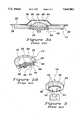
- FIG. 1is an exploded view of a prior art surface mounted medical electrode, illustrating the components which make up the electrode except for the abrasive electrolyte-containing member;
- FIGS. 2A and 2Bare cross-sectional views of the prior art electrode of FIG. 1;
- FIG. 3is a perspective view of the projecting stud of the prior art conductive member and the coupler of the prior art applicator gun illustrating the manner in which the applicator gun is connected to the stud of the prior art electrode of FIG. 1 for rotation of the conductive member by the applicator gun;
- FIG. 4is a schematic view of a prior art applicator gun used to drive the movable conductive element and abrasive member of the prior art electrode of FIG. 1 and the electrode of the present invention to perform skin preparation;
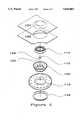
- FIG. 5is an exploded perspective view of a preferred form of the electrode of the present invention.
- FIG. 6is an elevated view of the bottom surface of the assembled electrode of the present invention shown in FIG. 5;
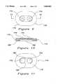
- FIG. 7is an elevated view of an alternate form of the electrode of the present invention.
- FIG. 8is a cross sectional view of the electrode of the present invention shown in FIG. 7 taken generally along lines 8--8 of FIG. 7;
- FIG. 9is an elevated view of an alternate form of the electrode of the present invention.
- FIG. 10is a cross sectional view of the alternate embodiment of the present invention shown in FIG. 9, taken generally along lines 10--10 of FIG. 9;
- FIG. 11is an elevated bottom view of the alternate embodiment shown in FIG. 9 with the electrolyte gel removed to show the center members.
- FIGS. 1-4illustrate a surface mounted electrode and applicator gun 70 of the prior art which are more fully set forth in U.S. Pat. Nos. 4,274,419 and 4,311,152. These patents are commonly owned by the assignee of the present invention and are incorporated herein as if fully set forth below.
- the prior art electrodes of FIGS. 1-4are described herein to provide a better understanding of the differences in structure and function of the prior art electrodes and the present invention.
- the prior art electrode shown in FIGS. 1-4generally consists of a circular sheet member 10 having an annular cutout portion 12 in the center thereof into which a collar 14 is inserted.
- the collar 14is shaped to hold an electrically conductive member 16 therein.
- a ring member 18is further employed to clamp around the upper portion of the collar 14.
- the sheet member 10is coated on one side with a skin adhesive layer 20.
- the adhesiveis protected during storage with a protective cover 22.
- a spongy abrasive member 24(see FIG. 2) is provided with an electrolyte gel thereon and is placed in contact with the conductive member 16. The abrasive member 24 is protected during storage with the protective cover 24.
- the prior art collar 14 of FIGS. 1-4has the general configuration of an inverted hat with a flat base surface 28 and a vertical wall surface 30 which is normal and integral with the flat base surface 28 and which terminates in a contoured flange 32.
- the flat base surface 28has an annular opening 34 in the center thereof with a diameter less than the diameter of the inner wall 30.
- Around the annular opening 34is a vertical wall 36 having slots 38 cut therein about every 90 degrees.
- the walls 30 and 36extend above the plane of the base 28 leaving a channel 40 therebetween.
- the collar 14is generally molded from a semi-flexible, nonconductive plastic material such as an acetate-based material, nylon, polyester, polyethylene or polypropylene.
- the wall 36is made sufficiently thin so that it can be flexed under pressure.
- the diameter of the collar 14is substantially greater than its height.
- the inner periphery of the wall 36is provided with a ridge 42 which functions to retain the conductive member therein.
- the prior art electrically conductive member 16 of FIGS. 1-4is adapted to be snapped into the collar 14.
- the electrically conductive member 16may be manufactured from a synthetic resin impregnated with carbon from a suitable electrically conductive metal or metal containing material or other suitable electrically conductive material.
- the electrically conductive member 16includes a lower portion 44 having a textured convex lower surface 45 and a thickness substantially equal to the depth of the cup formed by the flange 32, wall 30 and base 28 of the collar.
- Integral with the lower portion 44is an upper portion 46 of reduced diameter relative to the lower portion.
- the upper portion 46has a diameter equal to that of the annular opening 34 in the collar 14.
- the circumference of the upper portionhas a slot 48 therein which is interrupted by detents 50 positioned normal to the slot 48.
- the slot 48 of the conductive member 16receives the ridge 42 in the wall 36 of the collar 14 to prevent the conductive member from moving vertically within the collar.
- the detents 50 of the conductive member 16engage in the slots 38 in the flexible wall 36 of the collar 14 to prevent the conductive member from being rotated except by the predetermined torque/force of the applicator gun 70.
- a downwardly extending stud 52 provided on the bottom of the conductive member 16preferably includes a polygonal outer surface 54 so that the coupler of the applicator gun can be drivingly secured over the stud to rotate the conductive member 16.
- the prior art penetrating means for abrading or penetrating the epidermal layer of skinis a separate porous abrasive member 24 as illustrated in FIGS. 2A and 4.
- the abrasive member 24is a generally fibrous pad incorporating abrasive fibers and having a convexly curved surface 60 and a diameter substantially the same as the diameter of the lower portion 44 of the conductive member 16.
- a flange 58is folded against the edges of the abrasive member 24 to clamp the abrasive member 24 in the conductive member 16.
- the prior art abrasive member 24is loaded with electrolyte gel so that when the electrode is applied to the skin, the electrolyte gel provides electrical contact between the skin and the conductive member 16.
- the assembled collar 14, conductive member 16 and abrasive member 24are snapped together and placed in the annular opening 12 of the adhesive coated sheet member 10.
- the adhesive coating 20contacts the upper surface of the flange 32 of the collar 14 to secure the collar 14 in place relative to the sheet member.
- a snap ring 18 as shown in FIG. 1is snapped over the wall 30 of the collar.
- the snap ring 18is held in place by a ridge 62 extending around the outer terminating edge of the wall 30 of the collar 14.
- FIGS. 3 and 4generally illustrate the prior art applicator gun 70 which is used with the electrode described above as well as the present invention described below.
- the applicator gun 70generally includes a housing 72 within which is mounted an electric motor 74 driven by AC or DC current from a suitable current source.
- the motor illustratedis driven by a rechargeable battery 76 held in place in a quickly disconnectable case 78 which also serves as the handle of the applicator.
- the lower end of the caseincludes recessed electrical contacts 79 for battery recharging.
- the motorhas a shaft 80 to which a coupler 88 is attached.
- the coupler 88includes a polygonal recess 90 thereon which is shaped to receive the specifically shaped stud 52 of the electrode therein.
- FIGS. 5-11are illustrative of the preferred forms of the present invention.
- the electrode 110 of the present inventionis preferably a radiolucent member which consists generally of an electrically conductive center member 112 which is received in a circumferential housing 114.
- the housing 114includes a flexible screen member 116 received therein on the side of the housing 114 opposite to the center member 112.
- the electrode 100 of the present inventionmay further include an adhesive coated sheet member 118 surrounding a retaining ring 150.
- the sheet member 118is preferably formed of a cross linked polyethylene foam having an adhesive thereon to facilitate the attachment of the electrode 100 to the skin of the patient.
- the adhesive surface of the sheet member 118is protected by a paper-like protective cover 120, and the surface of the electrode is further protected in a tray-like package (not shown) or by a further protective cover 121.
- the center member 112is preferably a plastic carbon member having a thin silver plated layer thereon which has been treated with silver chloride to enhance ion flow therethrough as well as to form a low impedance point of connection with the wires (not shown) of the electrode.
- the center membermay be formed of a metal or other material to provide the desired conduction of the physiological signal from the skin of the patient to the signal acquisition device
- the center member 112 of the present embodimentincludes a generally flat first surface 122 which faces the skin of the patient in use.
- the center member 112includes a circularly shaped outer circumference having a diameter which is greater than the diameter of the aperture 134 in the housing 114 as described below.
- the second surface 124 of the center member 112faces away from the skin of the patient in use and preferably includes a pair of post members 126 and 128 extending therefrom.
- the post members 126 and 128preferably each include a tapered surface 129 thereon which extends from the second surface 124 of the center member 112.
- the tapered surface 129 of each post member 126 and 128preferably includes a slight rib 130 thereon and decrease in circumference to form a snap area 132 on each of the post members 126 and 128.
- the snap areasare contacted and engaged by a snap type of electrode connector (not shown) to supply physiological signals which originate from the same location for use by a plurality of signal acquisition devices.
- the rib 130is shaped to frictionally contact a portion of the housing 114 described below.
- the post members 126 and 128 of the present inventionare preferably not hexagonally or otherwise particularly shaped to receive reciprocal motion from the prior art applicator gun 70 (FIG. 4) thereon although the tip of the applicator gun may be readily modified to engage and rotate the pair of post members 126 and 128 as described above.
- the circumferential housing 114 of the present embodimentis preferably formed of a rigid plastic or similar material. As shown in FIGS. 6, the housing 114 includes an aperture 134 extending therethrough and first and second surfaces 136 and 138 respectively. The aperture 134 is formed to frictionally receive the center member 112 therein.
- the first surface 136 of the housing 114is best shown in FIG. 5.
- the first surface 136includes an outer circumferential rib 140 which forms the outer periphery of the housing 114 and an inwardly positioned annular ring shaped surface 142 having a plurality of channels 144 formed therein.
- the circumferential rib 140is crimped or otherwise formed to retain the screen member 116 thereon as shown in FIG. 6.
- a recessed area 146is also located inwardly of the annular surface 142 to surround the aperture 134 and receive the first and second surfaces 122 and 124 of the center member 112 therein.
- the second surface 138 of the housing 114preferably includes a generally flat contact surface 148 which is shaped to receive a portion of the retaining ring 150 thereagainst in a manner similar to the contact between the collar 14 and the conductive member 16 as shown in FIG. 2.
- the sidewall surface 154 of the housing 114extends outwardly from the contact surface 148 and includes a circumferential recess 152 therein.
- the circumferential recess 152is sized to frictionally receive a portion of the retaining ring 150 therein.
- the retaining ring 150 of the present inventionextends between the outer surface of the housing 114 and the sheet member 118 to retain the housing 114, center member 112 and screen member 116 while allowing relative movement between the housing 114 and retaining ring 150. Additionally, a snap ring 158 is positioned between the outer surface of the retaining ring 150 and the sheet member 118 to prevent movement between the sheet member 118 and the retaining ring 154.
- the screen member 116 of the present inventionis preferably constructed of a flexible silicon carbide or other abrasive material.
- the screen member 116is sized so that when the outer circumference of the screen member 116 is positioned generally inwardly from and adjacent to the crimped outer circumferential rib 140, the screen member 116 contacts the annular ring surface 142 of the housing 114 and is bowed slightly outwardly therefrom. This orientation is particularly useful to provide consistent abrasion of the skin of the patient because if the user of the applicator gun presses too hard during the preparation of the skin of the patient, the screen member 116 will preferably flex to decrease the abrasion of the skin.
- the flexibility of the screen member 116 and the orientation of the screen member 116 with respect to the housing 114 and center member 112may also be particularly important during the use of the electrode.
- the electrolyte gel(not shown) is preferably initially placed in the housing 114 to fill the space between the first surface 136 of the housing 114, the first surface 122 of the center member 112 and the screen member 116.
- the sheet member 118encircles the periphery of the housing 114 such that the electrolyte gel is trapped therein to provide for the electrical conduction of the physiological signal from the skin of the patient to the center member 112 and the signal acquisition device.
- ECG stress teststhe patient is exercising or otherwise moving around.
- This movementmay cause the skin which is in contact with the various electrodes to stretch or contract according to the movements of the patient. During this movement, the skin may press against or move away from the prior art electrodes. This movement between the electrode and the skin of the patient may cause muscle artifact and may even break the signal between the patient and the signal acquisition device.
- the electrolyte gelforms a gel column in the electrode which responds to the movement of the skin of the patient to ensure that the electrolyte gel maintains electrical contact between the skin of the patient and the center member 112.
- a gel form of the electrolyteis preferred, a solid or wet gel may also be used to maintain contact between the center member 112 and the skin of the patient.
- the area between the circumferential rib 140 and the annular surface 142 on the first surface 136 of the housing 114functions basically as a reservoir area 160 for the electrolyte gel in the present embodiment.
- the electrolyte gelis pushed back into the recess of the housing and is forced to flow to the outer periphery of the housing 114 through the channels 144 in the annular surface 142 to the reservoir area 160 of the housing 114 between the circumferential rib 140 and the annular surface 142.
- the electrolyte gelis drawn from the reservoir area 160 of the housing 114 through the channels 144 and into the recessed area 146 to ensure that a continuous column of electrolyte gel extends between the skin of the patient and the center member 112.
- FIGS. 7 and 8are illustrative of a further embodiment of the present invention wherein the pair of post members 126 and 128 are operatively connected to individual center members 166 and 168 rather than the common center member 112 as shown in FIGS. 5 and 6.
- the electrode assemblyincludes a pair of electrodes each having center members, housings, snap rings and the other components described above, all of which are commonly connected to a single sheet member 118 which retains the electrodes in a fixed and spaced apart relationship with respect to each other so that research and comparative studies performed with this electrode assembly may have a variability of a known quantity between each of the acquisition sites to allow the researcher and/or study coordinator to eliminate the effect of the distance between the signal acquisition sites as a variable in the study.
- the electrode assembly of this embodimentoperates generally in the same manner as the preferred embodiment; and, therefore, like numbers have been added to like members, and the features common to each embodiment are not separately repeated herein.
- FIGS. 9-11are illustrative of a further variation of an alternate form of electrode assembly 170 of the present invention wherein the electrode assembly includes a pair of center members 172 and 174 each having their own post members thereon, 176 and 178, respectively. As shown in FIG. 9, The center members 172 and 174 are preferably oriented horizontally along the electrode assembly 170. As shown in FIG. 10, the center members 172 and 174 are in operative and conductive contact with a recess 180 on the surface of the electrode assembly 170 which contacts the skin of the patient in use.
- the electrode assembly 170 of this embodimentconsists of the sheet member 118 with an adhesive on one surface thereof; the recess 180 which is shaped to receive a conductive material such as an electrolyte gel 182 therein and the center members 172 and 174 each having a post member 176 and 178 thereon.
- This embodimentis particularly adapted for use as a low cost electrode assembly 170 and includes the electrically conductive center members 172 and 174 operatively connected to a common centrally located recess area 180 which may be of nearly any desired shape.
- the center members 172 and 174are preferably positioned on a relatively small sheet member 118 and are spaced apart from each other a relatively small distance so that the snap connectors (not shown) may be connected thereto while the physiological signals are received from a common recess area 180 via the electrolyte gel 182 so that the acquisition devices are provided with physiological signals from a common source on the skin of the patient.
Landscapes
- Health & Medical Sciences (AREA)
- Life Sciences & Earth Sciences (AREA)
- Heart & Thoracic Surgery (AREA)
- Medical Informatics (AREA)
- Biophysics (AREA)
- Pathology (AREA)
- Engineering & Computer Science (AREA)
- Biomedical Technology (AREA)
- Cardiology (AREA)
- Physics & Mathematics (AREA)
- Molecular Biology (AREA)
- Surgery (AREA)
- Animal Behavior & Ethology (AREA)
- General Health & Medical Sciences (AREA)
- Public Health (AREA)
- Veterinary Medicine (AREA)
- Measurement And Recording Of Electrical Phenomena And Electrical Characteristics Of The Living Body (AREA)
Abstract
Description
Claims (17)
Priority Applications (1)
| Application Number | Priority Date | Filing Date | Title |
|---|---|---|---|
| US08/464,040US5645063A (en) | 1995-06-05 | 1995-06-05 | Skin electrode having multiple conductive center members |
Applications Claiming Priority (1)
| Application Number | Priority Date | Filing Date | Title |
|---|---|---|---|
| US08/464,040US5645063A (en) | 1995-06-05 | 1995-06-05 | Skin electrode having multiple conductive center members |
Publications (1)
| Publication Number | Publication Date |
|---|---|
| US5645063Atrue US5645063A (en) | 1997-07-08 |
Family
ID=23842290
Family Applications (1)
| Application Number | Title | Priority Date | Filing Date |
|---|---|---|---|
| US08/464,040Expired - Fee RelatedUS5645063A (en) | 1995-06-05 | 1995-06-05 | Skin electrode having multiple conductive center members |
Country Status (1)
| Country | Link |
|---|---|
| US (1) | US5645063A (en) |
Cited By (95)
| Publication number | Priority date | Publication date | Assignee | Title |
|---|---|---|---|---|
| US5740812A (en)* | 1996-01-25 | 1998-04-21 | Mindwaves, Ltd. | Apparatus for and method of providing brainwave biofeedback |
| US5983129A (en)* | 1998-02-19 | 1999-11-09 | Cowan; Jonathan D. | Method for determining an individual's intensity of focused attention and integrating same into computer program |
| WO2002005711A1 (en)* | 2000-07-19 | 2002-01-24 | C 2 C Sa | Device for acquiring electric signals coming from the human body and more particularly from the heart |
| US6434421B1 (en) | 2000-01-31 | 2002-08-13 | Integrated Biosensing Technologies | Biopotential sensor electrode |
| US6434420B1 (en) | 2000-01-31 | 2002-08-13 | Integrated Biosensing Technologies | Biopotential electrode sensory component |
| US6438413B1 (en) | 2000-01-31 | 2002-08-20 | Integrated Biosensing Technologies | Biopotential sensor electrode system |
| US6564079B1 (en) | 2000-07-27 | 2003-05-13 | Ckm Diagnostics, Inc. | Electrode array and skin attachment system for noninvasive nerve location and imaging device |
| US20030171661A1 (en)* | 2002-01-29 | 2003-09-11 | Southwest Research Institute | Electrode systems and methods for reducing motion artifact |
| US6622035B1 (en) | 2000-01-21 | 2003-09-16 | Instrumentarium Corp. | Electrode for measurement of weak bioelectrical signals |
| US20030203879A1 (en)* | 1999-09-09 | 2003-10-30 | Schering Ag | Calcium complex of [[(4R)-4-[bis[(carboxy-.kappa.O)methyl]amino-.kappa.n]-6,9-bis[(carboxy.kappa.O)methyl]-1-[(4,4-diphenylcyclohexy)oxy]-1-hydroxy-2-oxa-6,9-diaza-1-phosphaundecan-11-ylic-acid-.kappa.N6,.Kappa.N9,.Kappa 011]1-oxidato(6-)]-, hexahydrogen, its salts, pharmaceutical agents that contain these complexes, their use in treatment and as additives in diagnosis, as well as processes for the production of the complexes and agents |
| US20040054393A1 (en)* | 2000-01-21 | 2004-03-18 | Goran Stemme | Medical electrode |
| US20060128193A1 (en)* | 2004-11-22 | 2006-06-15 | Cardiodynamics International Corporation | Methods and apparatus for conducting electrical current |
| US20070293926A1 (en)* | 1995-10-27 | 2007-12-20 | Ed Dunlay | Electrodes for use in treatment of oropharyngeal disorders by application of neuromuscular electrical stimulation |
| US20080020037A1 (en)* | 2006-07-11 | 2008-01-24 | Robertson Timothy L | Acoustic Pharma-Informatics System |
| WO2008068695A1 (en)* | 2006-12-07 | 2008-06-12 | Koninklijke Philips Electronics N.V. | Handheld, repositionable ecg detector |
| WO2008092098A3 (en)* | 2007-01-25 | 2008-10-09 | Lifesync Corp A Delaware Corp | Radiolucent electrode or sensor assembly |
| US20090227857A1 (en)* | 2008-03-06 | 2009-09-10 | Chuck Rowe | Biomedical electrode |
| US20100234909A1 (en)* | 2007-11-08 | 2010-09-16 | Koninklijke Philips Electronics N.V. | Repositionable Electrode and Systems and Methods for Identifying Electrode Position for Cardiotherapy |
| US7978064B2 (en) | 2005-04-28 | 2011-07-12 | Proteus Biomedical, Inc. | Communication system with partial power source |
| US8036748B2 (en) | 2008-11-13 | 2011-10-11 | Proteus Biomedical, Inc. | Ingestible therapy activator system and method |
| US8055334B2 (en) | 2008-12-11 | 2011-11-08 | Proteus Biomedical, Inc. | Evaluation of gastrointestinal function using portable electroviscerography systems and methods of using the same |
| US8054140B2 (en) | 2006-10-17 | 2011-11-08 | Proteus Biomedical, Inc. | Low voltage oscillator for medical devices |
| US8114021B2 (en) | 2008-12-15 | 2012-02-14 | Proteus Biomedical, Inc. | Body-associated receiver and method |
| US8115618B2 (en) | 2007-05-24 | 2012-02-14 | Proteus Biomedical, Inc. | RFID antenna for in-body device |
| US8258962B2 (en) | 2008-03-05 | 2012-09-04 | Proteus Biomedical, Inc. | Multi-mode communication ingestible event markers and systems, and methods of using the same |
| US8540633B2 (en) | 2008-08-13 | 2013-09-24 | Proteus Digital Health, Inc. | Identifier circuits for generating unique identifiable indicators and techniques for producing same |
| US8540664B2 (en) | 2009-03-25 | 2013-09-24 | Proteus Digital Health, Inc. | Probablistic pharmacokinetic and pharmacodynamic modeling |
| US8545402B2 (en) | 2009-04-28 | 2013-10-01 | Proteus Digital Health, Inc. | Highly reliable ingestible event markers and methods for using the same |
| US8548558B2 (en) | 2008-03-06 | 2013-10-01 | Covidien Lp | Electrode capable of attachment to a garment, system, and methods of manufacturing |
| US8547248B2 (en) | 2005-09-01 | 2013-10-01 | Proteus Digital Health, Inc. | Implantable zero-wire communications system |
| US8558563B2 (en) | 2009-08-21 | 2013-10-15 | Proteus Digital Health, Inc. | Apparatus and method for measuring biochemical parameters |
| US8597186B2 (en) | 2009-01-06 | 2013-12-03 | Proteus Digital Health, Inc. | Pharmaceutical dosages delivery system |
| US8718193B2 (en) | 2006-11-20 | 2014-05-06 | Proteus Digital Health, Inc. | Active signal processing personal health signal receivers |
| US8730031B2 (en) | 2005-04-28 | 2014-05-20 | Proteus Digital Health, Inc. | Communication system using an implantable device |
| WO2014102459A1 (en)* | 2012-12-31 | 2014-07-03 | Suunto Oy | Electrode assembly |
| US8784308B2 (en) | 2009-12-02 | 2014-07-22 | Proteus Digital Health, Inc. | Integrated ingestible event marker system with pharmaceutical product |
| US8802183B2 (en) | 2005-04-28 | 2014-08-12 | Proteus Digital Health, Inc. | Communication system with enhanced partial power source and method of manufacturing same |
| US8814574B2 (en) | 2012-12-31 | 2014-08-26 | Suunto Oy | Male end of a telemetric transceiver |
| US8836513B2 (en) | 2006-04-28 | 2014-09-16 | Proteus Digital Health, Inc. | Communication system incorporated in an ingestible product |
| US8858432B2 (en) | 2007-02-01 | 2014-10-14 | Proteus Digital Health, Inc. | Ingestible event marker systems |
| US8868453B2 (en) | 2009-11-04 | 2014-10-21 | Proteus Digital Health, Inc. | System for supply chain management |
| US8868216B2 (en) | 2008-11-21 | 2014-10-21 | Covidien Lp | Electrode garment |
| US8912908B2 (en) | 2005-04-28 | 2014-12-16 | Proteus Digital Health, Inc. | Communication system with remote activation |
| US8932221B2 (en) | 2007-03-09 | 2015-01-13 | Proteus Digital Health, Inc. | In-body device having a multi-directional transmitter |
| US8945005B2 (en) | 2006-10-25 | 2015-02-03 | Proteus Digital Health, Inc. | Controlled activation ingestible identifier |
| US8956287B2 (en) | 2006-05-02 | 2015-02-17 | Proteus Digital Health, Inc. | Patient customized therapeutic regimens |
| US8956288B2 (en) | 2007-02-14 | 2015-02-17 | Proteus Digital Health, Inc. | In-body power source having high surface area electrode |
| US8961412B2 (en) | 2007-09-25 | 2015-02-24 | Proteus Digital Health, Inc. | In-body device with virtual dipole signal amplification |
| US9014779B2 (en) | 2010-02-01 | 2015-04-21 | Proteus Digital Health, Inc. | Data gathering system |
| US9055879B2 (en) | 2013-06-14 | 2015-06-16 | Suunto Oy | Device and method for assembling an electronic device and a flexible element for facilitating assembly of electronic components |
| US9107806B2 (en) | 2010-11-22 | 2015-08-18 | Proteus Digital Health, Inc. | Ingestible device with pharmaceutical product |
| US9149423B2 (en) | 2009-05-12 | 2015-10-06 | Proteus Digital Health, Inc. | Ingestible event markers comprising an ingestible component |
| US9173670B2 (en) | 2013-04-08 | 2015-11-03 | Irhythm Technologies, Inc. | Skin abrader |
| US9198608B2 (en) | 2005-04-28 | 2015-12-01 | Proteus Digital Health, Inc. | Communication system incorporated in a container |
| US9235683B2 (en) | 2011-11-09 | 2016-01-12 | Proteus Digital Health, Inc. | Apparatus, system, and method for managing adherence to a regimen |
| US9270503B2 (en) | 2013-09-20 | 2016-02-23 | Proteus Digital Health, Inc. | Methods, devices and systems for receiving and decoding a signal in the presence of noise using slices and warping |
| US9268909B2 (en) | 2012-10-18 | 2016-02-23 | Proteus Digital Health, Inc. | Apparatus, system, and method to adaptively optimize power dissipation and broadcast power in a power source for a communication device |
| US9270025B2 (en) | 2007-03-09 | 2016-02-23 | Proteus Digital Health, Inc. | In-body device having deployable antenna |
| US9271897B2 (en) | 2012-07-23 | 2016-03-01 | Proteus Digital Health, Inc. | Techniques for manufacturing ingestible event markers comprising an ingestible component |
| US9439566B2 (en) | 2008-12-15 | 2016-09-13 | Proteus Digital Health, Inc. | Re-wearable wireless device |
| US9439599B2 (en) | 2011-03-11 | 2016-09-13 | Proteus Digital Health, Inc. | Wearable personal body associated device with various physical configurations |
| US20160302684A1 (en)* | 2015-04-14 | 2016-10-20 | LifeWatch Technologies, Ltd. | Electrode housing and a monitoring device |
| US9577864B2 (en) | 2013-09-24 | 2017-02-21 | Proteus Digital Health, Inc. | Method and apparatus for use with received electromagnetic signal at a frequency not known exactly in advance |
| US9597004B2 (en) | 2014-10-31 | 2017-03-21 | Irhythm Technologies, Inc. | Wearable monitor |
| US9597487B2 (en) | 2010-04-07 | 2017-03-21 | Proteus Digital Health, Inc. | Miniature ingestible device |
| US9603550B2 (en) | 2008-07-08 | 2017-03-28 | Proteus Digital Health, Inc. | State characterization based on multi-variate data fusion techniques |
| US9659423B2 (en) | 2008-12-15 | 2017-05-23 | Proteus Digital Health, Inc. | Personal authentication apparatus system and method |
| US9756874B2 (en) | 2011-07-11 | 2017-09-12 | Proteus Digital Health, Inc. | Masticable ingestible product and communication system therefor |
| US20170265767A1 (en)* | 2012-12-31 | 2017-09-21 | Suunto Oy | Electrode assembly |
| US9796576B2 (en) | 2013-08-30 | 2017-10-24 | Proteus Digital Health, Inc. | Container with electronically controlled interlock |
| EP2464283A4 (en)* | 2009-08-14 | 2017-10-25 | David Burton | Anaesthesia and consciousness depth monitoring system |
| US9819122B1 (en)* | 2016-06-29 | 2017-11-14 | Intel Corporation | Apparel compute device connection |
| US9861291B2 (en) | 2012-12-31 | 2018-01-09 | Suunto Oy | Electrode assembly |
| US9883819B2 (en) | 2009-01-06 | 2018-02-06 | Proteus Digital Health, Inc. | Ingestion-related biofeedback and personalized medical therapy method and system |
| US10084880B2 (en) | 2013-11-04 | 2018-09-25 | Proteus Digital Health, Inc. | Social media networking based on physiologic information |
| US10175376B2 (en) | 2013-03-15 | 2019-01-08 | Proteus Digital Health, Inc. | Metal detector apparatus, system, and method |
| US10187121B2 (en) | 2016-07-22 | 2019-01-22 | Proteus Digital Health, Inc. | Electromagnetic sensing and detection of ingestible event markers |
| US10223905B2 (en) | 2011-07-21 | 2019-03-05 | Proteus Digital Health, Inc. | Mobile device and system for detection and communication of information received from an ingestible device |
| US10271754B2 (en) | 2013-01-24 | 2019-04-30 | Irhythm Technologies, Inc. | Physiological monitoring device |
| US10398377B2 (en)* | 2015-09-04 | 2019-09-03 | Japan Science And Technology Agency | Connector substrate, sensor system, and wearable sensor system |
| US10398161B2 (en) | 2014-01-21 | 2019-09-03 | Proteus Digital Heal Th, Inc. | Masticable ingestible product and communication system therefor |
| US10405799B2 (en) | 2010-05-12 | 2019-09-10 | Irhythm Technologies, Inc. | Device features and design elements for long-term adhesion |
| US10529044B2 (en) | 2010-05-19 | 2020-01-07 | Proteus Digital Health, Inc. | Tracking and delivery confirmation of pharmaceutical products |
| US11051543B2 (en) | 2015-07-21 | 2021-07-06 | Otsuka Pharmaceutical Co. Ltd. | Alginate on adhesive bilayer laminate film |
| US11083371B1 (en) | 2020-02-12 | 2021-08-10 | Irhythm Technologies, Inc. | Methods and systems for processing data via an executable file on a monitor to reduce the dimensionality of the data and encrypting the data being transmitted over the wireless network |
| US11147465B2 (en) | 2015-05-05 | 2021-10-19 | Welch Allyn, Inc. | Abrasive electrode |
| US11149123B2 (en) | 2013-01-29 | 2021-10-19 | Otsuka Pharmaceutical Co., Ltd. | Highly-swellable polymeric films and compositions comprising the same |
| US11158149B2 (en) | 2013-03-15 | 2021-10-26 | Otsuka Pharmaceutical Co., Ltd. | Personal authentication apparatus system and method |
| US11246523B1 (en) | 2020-08-06 | 2022-02-15 | Irhythm Technologies, Inc. | Wearable device with conductive traces and insulator |
| US11350864B2 (en) | 2020-08-06 | 2022-06-07 | Irhythm Technologies, Inc. | Adhesive physiological monitoring device |
| US11529071B2 (en) | 2016-10-26 | 2022-12-20 | Otsuka Pharmaceutical Co., Ltd. | Methods for manufacturing capsules with ingestible event markers |
| US11642062B2 (en)* | 2015-03-10 | 2023-05-09 | Siemens Healthcare Gmbh | Production of electrical contact with skin |
| US11744481B2 (en) | 2013-03-15 | 2023-09-05 | Otsuka Pharmaceutical Co., Ltd. | System, apparatus and methods for data collection and assessing outcomes |
| US11944441B2 (en) | 2012-12-31 | 2024-04-02 | Suunto Oy | Electro-mechanic assembly and integrated snap connectors |
| USD1063079S1 (en) | 2021-08-06 | 2025-02-18 | Irhythm Technologies, Inc. | Physiological monitoring device |
Citations (35)
| Publication number | Priority date | Publication date | Assignee | Title |
|---|---|---|---|---|
| US2621657A (en)* | 1950-09-19 | 1952-12-16 | Clifton B Leech | Electrocardiographic electrode |
| US3882853A (en)* | 1973-02-15 | 1975-05-13 | Cardiodynamics | Biomedical electrode |
| US4029086A (en)* | 1975-08-11 | 1977-06-14 | Consolidated Medical Equipment, Inc. | Electrode arrangement |
| US4155354A (en)* | 1976-03-29 | 1979-05-22 | Rasmussen Steen B | Disposable electromedical electrode and a set of such electrodes |
| US4257424A (en)* | 1979-04-30 | 1981-03-24 | Ndm Corporation | X-ray transparent medical electrode |
| US4265253A (en)* | 1979-07-09 | 1981-05-05 | Consolidated Medical Equipment Inc. | Skin conducting electrode and electrode assembly |
| US4270544A (en)* | 1979-05-21 | 1981-06-02 | Texas Instruments Incorporated | Medical electrode having improved adherence characteristics |
| US4274419A (en)* | 1979-10-19 | 1981-06-23 | Quinton Instrument Co. | Skin preparation device and method used in the application of medical electrodes |
| US4300575A (en)* | 1979-06-25 | 1981-11-17 | Staodynamics, Inc. | Air-permeable disposable electrode |
| US4311152A (en)* | 1979-01-15 | 1982-01-19 | Quinton Instrument Co. | Medical electrode and system for minimizing motion artifacts |
| US4319579A (en)* | 1979-06-21 | 1982-03-16 | Ndm Corporation | Reusable medical electrode having disposable electrolyte carrier |
| US4331153A (en)* | 1980-11-13 | 1982-05-25 | Healy James W | Disposable EKG electrode |
| US4488557A (en)* | 1984-03-02 | 1984-12-18 | Engel Rolf R | Topical agent for transcutaneous measurement of partial pressure of oxygen |
| US4524087A (en)* | 1980-01-23 | 1985-06-18 | Minnesota Mining And Manufacturing Company | Conductive adhesive and biomedical electrode |
| US4539996A (en)* | 1980-01-23 | 1985-09-10 | Minnesota Mining And Manufacturing Company | Conductive adhesive and biomedical electrode |
| US4559950A (en)* | 1983-11-25 | 1985-12-24 | Graphic Controls Corporation | Disposable biomedical and diagnostic electrode |
| US4595013A (en)* | 1984-08-17 | 1986-06-17 | Neurologics, Inc. | Electrode harness |
| US4635641A (en)* | 1985-10-16 | 1987-01-13 | Murray Electronics Associates Limited | Multi-element electrode |
| US4660562A (en)* | 1985-03-07 | 1987-04-28 | House Sr Hugh A | Multi-event biomedical electrode assembly |
| US4669480A (en)* | 1985-10-16 | 1987-06-02 | Murray Electronics Associates Limited Partnership | Temperature indicating electrotherapy electrode/coil and method of use |
| US4674511A (en)* | 1979-04-30 | 1987-06-23 | American Hospital Supply Corporation | Medical electrode |
| US4679564A (en)* | 1984-10-04 | 1987-07-14 | Sessions Robert W | Monitoring electrode attachable to a patient |
| US4700710A (en)* | 1985-03-12 | 1987-10-20 | Murray Electronics Associates Limited Partnership | Apertured adhesively applied body electrode apparatus and method |
| US4706680A (en)* | 1986-06-30 | 1987-11-17 | Nepera Inc. | Conductive adhesive medical electrode assemblies |
| US4738263A (en)* | 1986-04-16 | 1988-04-19 | Baxter Travenol Laboratories, Inc. | Electrosurgical electrode connector |
| US4757817A (en)* | 1987-03-09 | 1988-07-19 | Lead-Lok, Inc. | Adhesive electrode pad |
| USRE32724E (en) | 1979-06-21 | 1988-08-02 | American Hospital Supply Corporation | Reusable medical electrode having disposable electrolyte carrier |
| US4768514A (en)* | 1985-06-04 | 1988-09-06 | C. R. Bard, Inc. | Medical electrode |
| US4777954A (en)* | 1986-06-30 | 1988-10-18 | Nepera Inc. | Conductive adhesive medical electrode assemblies |
| US4798208A (en)* | 1987-12-09 | 1989-01-17 | Faasse Jr Adrian L | Diagnostic electrode |
| US4838273A (en)* | 1979-04-30 | 1989-06-13 | Baxter International Inc. | Medical electrode |
| US4934383A (en)* | 1982-04-23 | 1990-06-19 | George Glumac | Electrode |
| GB2240928A (en)* | 1990-02-20 | 1991-08-21 | Polymedical Limited | Skin contact electrode |
| US5114424A (en)* | 1989-09-07 | 1992-05-19 | Siemens Aktiengesellschaft | Multipart planar electrode for an hf-surgery device |
| US5458141A (en)* | 1993-08-04 | 1995-10-17 | Quinton Instrument Company | Abrasive skin electrode |
- 1995
- 1995-06-05USUS08/464,040patent/US5645063A/ennot_activeExpired - Fee Related
Patent Citations (35)
| Publication number | Priority date | Publication date | Assignee | Title |
|---|---|---|---|---|
| US2621657A (en)* | 1950-09-19 | 1952-12-16 | Clifton B Leech | Electrocardiographic electrode |
| US3882853A (en)* | 1973-02-15 | 1975-05-13 | Cardiodynamics | Biomedical electrode |
| US4029086A (en)* | 1975-08-11 | 1977-06-14 | Consolidated Medical Equipment, Inc. | Electrode arrangement |
| US4155354A (en)* | 1976-03-29 | 1979-05-22 | Rasmussen Steen B | Disposable electromedical electrode and a set of such electrodes |
| US4311152A (en)* | 1979-01-15 | 1982-01-19 | Quinton Instrument Co. | Medical electrode and system for minimizing motion artifacts |
| US4257424A (en)* | 1979-04-30 | 1981-03-24 | Ndm Corporation | X-ray transparent medical electrode |
| US4674511A (en)* | 1979-04-30 | 1987-06-23 | American Hospital Supply Corporation | Medical electrode |
| US4838273A (en)* | 1979-04-30 | 1989-06-13 | Baxter International Inc. | Medical electrode |
| US4270544A (en)* | 1979-05-21 | 1981-06-02 | Texas Instruments Incorporated | Medical electrode having improved adherence characteristics |
| USRE32724E (en) | 1979-06-21 | 1988-08-02 | American Hospital Supply Corporation | Reusable medical electrode having disposable electrolyte carrier |
| US4319579A (en)* | 1979-06-21 | 1982-03-16 | Ndm Corporation | Reusable medical electrode having disposable electrolyte carrier |
| US4300575A (en)* | 1979-06-25 | 1981-11-17 | Staodynamics, Inc. | Air-permeable disposable electrode |
| US4265253A (en)* | 1979-07-09 | 1981-05-05 | Consolidated Medical Equipment Inc. | Skin conducting electrode and electrode assembly |
| US4274419A (en)* | 1979-10-19 | 1981-06-23 | Quinton Instrument Co. | Skin preparation device and method used in the application of medical electrodes |
| US4524087A (en)* | 1980-01-23 | 1985-06-18 | Minnesota Mining And Manufacturing Company | Conductive adhesive and biomedical electrode |
| US4539996A (en)* | 1980-01-23 | 1985-09-10 | Minnesota Mining And Manufacturing Company | Conductive adhesive and biomedical electrode |
| US4331153A (en)* | 1980-11-13 | 1982-05-25 | Healy James W | Disposable EKG electrode |
| US4934383A (en)* | 1982-04-23 | 1990-06-19 | George Glumac | Electrode |
| US4559950A (en)* | 1983-11-25 | 1985-12-24 | Graphic Controls Corporation | Disposable biomedical and diagnostic electrode |
| US4488557A (en)* | 1984-03-02 | 1984-12-18 | Engel Rolf R | Topical agent for transcutaneous measurement of partial pressure of oxygen |
| US4595013A (en)* | 1984-08-17 | 1986-06-17 | Neurologics, Inc. | Electrode harness |
| US4679564A (en)* | 1984-10-04 | 1987-07-14 | Sessions Robert W | Monitoring electrode attachable to a patient |
| US4660562A (en)* | 1985-03-07 | 1987-04-28 | House Sr Hugh A | Multi-event biomedical electrode assembly |
| US4700710A (en)* | 1985-03-12 | 1987-10-20 | Murray Electronics Associates Limited Partnership | Apertured adhesively applied body electrode apparatus and method |
| US4768514A (en)* | 1985-06-04 | 1988-09-06 | C. R. Bard, Inc. | Medical electrode |
| US4669480A (en)* | 1985-10-16 | 1987-06-02 | Murray Electronics Associates Limited Partnership | Temperature indicating electrotherapy electrode/coil and method of use |
| US4635641A (en)* | 1985-10-16 | 1987-01-13 | Murray Electronics Associates Limited | Multi-element electrode |
| US4738263A (en)* | 1986-04-16 | 1988-04-19 | Baxter Travenol Laboratories, Inc. | Electrosurgical electrode connector |
| US4777954A (en)* | 1986-06-30 | 1988-10-18 | Nepera Inc. | Conductive adhesive medical electrode assemblies |
| US4706680A (en)* | 1986-06-30 | 1987-11-17 | Nepera Inc. | Conductive adhesive medical electrode assemblies |
| US4757817A (en)* | 1987-03-09 | 1988-07-19 | Lead-Lok, Inc. | Adhesive electrode pad |
| US4798208A (en)* | 1987-12-09 | 1989-01-17 | Faasse Jr Adrian L | Diagnostic electrode |
| US5114424A (en)* | 1989-09-07 | 1992-05-19 | Siemens Aktiengesellschaft | Multipart planar electrode for an hf-surgery device |
| GB2240928A (en)* | 1990-02-20 | 1991-08-21 | Polymedical Limited | Skin contact electrode |
| US5458141A (en)* | 1993-08-04 | 1995-10-17 | Quinton Instrument Company | Abrasive skin electrode |
Non-Patent Citations (8)
| Title |
|---|
| 3M Co., "3M Announces the New High Performance Red Dot® Monitoring Electrode" brochure, date unknown, 5 pages. |
| 3M Co., 3M Announces the New High Performance Red Dot Monitoring Electrode brochure, date unknown, 5 pages.* |
| Ferris Mfg., Co., "Ferris Trace-Itt Pregelled Disposable Pads for the EKG Lab" literature, date unknown, 1 page. |
| Ferris Mfg., Co., Ferris Trace Itt Pregelled Disposable Pads for the EKG Lab literature, date unknown, 1 page.* |
| Medtronic Andover Medical, "ClearTrace™ Monitoring Electrode with Adhesive Gel" literature, date unknown, 1 page. |
| Medtronic Andover Medical, ClearTrace Monitoring Electrode with Adhesive Gel literature, date unknown, 1 page.* |
| Ver Med, Ver Med Breathable Electrode brochure, date unknown, 2 pages.* |
| Ver-Med, "Ver-Med Breathable Electrode" brochure, date unknown, 2 pages. |
Cited By (210)
| Publication number | Priority date | Publication date | Assignee | Title |
|---|---|---|---|---|
| US8965535B2 (en)* | 1995-10-27 | 2015-02-24 | Esd Limited Liability Company | Electrodes for use in treatment of oropharyngeal disorders by application of neuromuscular electrical stimulation |
| US20070293926A1 (en)* | 1995-10-27 | 2007-12-20 | Ed Dunlay | Electrodes for use in treatment of oropharyngeal disorders by application of neuromuscular electrical stimulation |
| US5740812A (en)* | 1996-01-25 | 1998-04-21 | Mindwaves, Ltd. | Apparatus for and method of providing brainwave biofeedback |
| US5983129A (en)* | 1998-02-19 | 1999-11-09 | Cowan; Jonathan D. | Method for determining an individual's intensity of focused attention and integrating same into computer program |
| US20030203879A1 (en)* | 1999-09-09 | 2003-10-30 | Schering Ag | Calcium complex of [[(4R)-4-[bis[(carboxy-.kappa.O)methyl]amino-.kappa.n]-6,9-bis[(carboxy.kappa.O)methyl]-1-[(4,4-diphenylcyclohexy)oxy]-1-hydroxy-2-oxa-6,9-diaza-1-phosphaundecan-11-ylic-acid-.kappa.N6,.Kappa.N9,.Kappa 011]1-oxidato(6-)]-, hexahydrogen, its salts, pharmaceutical agents that contain these complexes, their use in treatment and as additives in diagnosis, as well as processes for the production of the complexes and agents |
| US6622035B1 (en) | 2000-01-21 | 2003-09-16 | Instrumentarium Corp. | Electrode for measurement of weak bioelectrical signals |
| US20040054393A1 (en)* | 2000-01-21 | 2004-03-18 | Goran Stemme | Medical electrode |
| US6434420B1 (en) | 2000-01-31 | 2002-08-13 | Integrated Biosensing Technologies | Biopotential electrode sensory component |
| US6438413B1 (en) | 2000-01-31 | 2002-08-20 | Integrated Biosensing Technologies | Biopotential sensor electrode system |
| US6434421B1 (en) | 2000-01-31 | 2002-08-13 | Integrated Biosensing Technologies | Biopotential sensor electrode |
| US20030191401A1 (en)* | 2000-07-19 | 2003-10-09 | David Oury | Device for acquiring electric signals coming from the human body and more particularly from the heart |
| US20070004987A1 (en)* | 2000-07-19 | 2007-01-04 | C 2 C Sa | Device for acquiring electric signals coming from the human body and more particularly from the heart |
| FR2811878A1 (en)* | 2000-07-19 | 2002-01-25 | C2C | DEVICE FOR ACQUIRING ELECTRIC SIGNALS FROM THE HUMAN BODY AND MORE PARTICULARLY FOR THE ACQUISITION OF ELECTRIC SIGNALS FROM THE HEART |
| WO2002005711A1 (en)* | 2000-07-19 | 2002-01-24 | C 2 C Sa | Device for acquiring electric signals coming from the human body and more particularly from the heart |
| US6609018B2 (en) | 2000-07-27 | 2003-08-19 | Ckm Diagnostics, Inc. | Electrode array and sensor attachment system for noninvasive nerve location and imaging device |
| US6564079B1 (en) | 2000-07-27 | 2003-05-13 | Ckm Diagnostics, Inc. | Electrode array and skin attachment system for noninvasive nerve location and imaging device |
| US20030171661A1 (en)* | 2002-01-29 | 2003-09-11 | Southwest Research Institute | Electrode systems and methods for reducing motion artifact |
| US6912414B2 (en) | 2002-01-29 | 2005-06-28 | Southwest Research Institute | Electrode systems and methods for reducing motion artifact |
| US20060128193A1 (en)* | 2004-11-22 | 2006-06-15 | Cardiodynamics International Corporation | Methods and apparatus for conducting electrical current |
| US7270580B2 (en) | 2004-11-22 | 2007-09-18 | Cardio Dynamics International Corporation | Methods and apparatus for conducting electrical current |
| US7978064B2 (en) | 2005-04-28 | 2011-07-12 | Proteus Biomedical, Inc. | Communication system with partial power source |
| US8674825B2 (en) | 2005-04-28 | 2014-03-18 | Proteus Digital Health, Inc. | Pharma-informatics system |
| US9439582B2 (en) | 2005-04-28 | 2016-09-13 | Proteus Digital Health, Inc. | Communication system with remote activation |
| US10517507B2 (en) | 2005-04-28 | 2019-12-31 | Proteus Digital Health, Inc. | Communication system with enhanced partial power source and method of manufacturing same |
| US8816847B2 (en) | 2005-04-28 | 2014-08-26 | Proteus Digital Health, Inc. | Communication system with partial power source |
| US9198608B2 (en) | 2005-04-28 | 2015-12-01 | Proteus Digital Health, Inc. | Communication system incorporated in a container |
| US8847766B2 (en) | 2005-04-28 | 2014-09-30 | Proteus Digital Health, Inc. | Pharma-informatics system |
| US9597010B2 (en) | 2005-04-28 | 2017-03-21 | Proteus Digital Health, Inc. | Communication system using an implantable device |
| US9161707B2 (en) | 2005-04-28 | 2015-10-20 | Proteus Digital Health, Inc. | Communication system incorporated in an ingestible product |
| US8802183B2 (en) | 2005-04-28 | 2014-08-12 | Proteus Digital Health, Inc. | Communication system with enhanced partial power source and method of manufacturing same |
| US10542909B2 (en) | 2005-04-28 | 2020-01-28 | Proteus Digital Health, Inc. | Communication system with partial power source |
| US9649066B2 (en) | 2005-04-28 | 2017-05-16 | Proteus Digital Health, Inc. | Communication system with partial power source |
| US10610128B2 (en) | 2005-04-28 | 2020-04-07 | Proteus Digital Health, Inc. | Pharma-informatics system |
| US8730031B2 (en) | 2005-04-28 | 2014-05-20 | Proteus Digital Health, Inc. | Communication system using an implantable device |
| US9119554B2 (en) | 2005-04-28 | 2015-09-01 | Proteus Digital Health, Inc. | Pharma-informatics system |
| US9681842B2 (en) | 2005-04-28 | 2017-06-20 | Proteus Digital Health, Inc. | Pharma-informatics system |
| US9962107B2 (en) | 2005-04-28 | 2018-05-08 | Proteus Digital Health, Inc. | Communication system with enhanced partial power source and method of manufacturing same |
| US11476952B2 (en) | 2005-04-28 | 2022-10-18 | Otsuka Pharmaceutical Co., Ltd. | Pharma-informatics system |
| US8912908B2 (en) | 2005-04-28 | 2014-12-16 | Proteus Digital Health, Inc. | Communication system with remote activation |
| US8547248B2 (en) | 2005-09-01 | 2013-10-01 | Proteus Digital Health, Inc. | Implantable zero-wire communications system |
| US8836513B2 (en) | 2006-04-28 | 2014-09-16 | Proteus Digital Health, Inc. | Communication system incorporated in an ingestible product |
| US11928614B2 (en) | 2006-05-02 | 2024-03-12 | Otsuka Pharmaceutical Co., Ltd. | Patient customized therapeutic regimens |
| US8956287B2 (en) | 2006-05-02 | 2015-02-17 | Proteus Digital Health, Inc. | Patient customized therapeutic regimens |
| US20080020037A1 (en)* | 2006-07-11 | 2008-01-24 | Robertson Timothy L | Acoustic Pharma-Informatics System |
| US8054140B2 (en) | 2006-10-17 | 2011-11-08 | Proteus Biomedical, Inc. | Low voltage oscillator for medical devices |
| US8945005B2 (en) | 2006-10-25 | 2015-02-03 | Proteus Digital Health, Inc. | Controlled activation ingestible identifier |
| US10238604B2 (en) | 2006-10-25 | 2019-03-26 | Proteus Digital Health, Inc. | Controlled activation ingestible identifier |
| US11357730B2 (en) | 2006-10-25 | 2022-06-14 | Otsuka Pharmaceutical Co., Ltd. | Controlled activation ingestible identifier |
| US9444503B2 (en) | 2006-11-20 | 2016-09-13 | Proteus Digital Health, Inc. | Active signal processing personal health signal receivers |
| US8718193B2 (en) | 2006-11-20 | 2014-05-06 | Proteus Digital Health, Inc. | Active signal processing personal health signal receivers |
| US9083589B2 (en) | 2006-11-20 | 2015-07-14 | Proteus Digital Health, Inc. | Active signal processing personal health signal receivers |
| US8315687B2 (en) | 2006-12-07 | 2012-11-20 | Koninklijke Philips Electronics N.V. | Handheld, repositionable ECG detector |
| WO2008068695A1 (en)* | 2006-12-07 | 2008-06-12 | Koninklijke Philips Electronics N.V. | Handheld, repositionable ecg detector |
| JP2010511465A (en)* | 2006-12-07 | 2010-04-15 | コーニンクレッカ フィリップス エレクトロニクス エヌ ヴィ | ECG detector capable of handheld repositioning |
| US20100081913A1 (en)* | 2006-12-07 | 2010-04-01 | Koninklijke Philips Electronics N.V. | Handheld, repositionable ecg detector |
| WO2008092098A3 (en)* | 2007-01-25 | 2008-10-09 | Lifesync Corp A Delaware Corp | Radiolucent electrode or sensor assembly |
| US8858432B2 (en) | 2007-02-01 | 2014-10-14 | Proteus Digital Health, Inc. | Ingestible event marker systems |
| US10441194B2 (en) | 2007-02-01 | 2019-10-15 | Proteus Digital Heal Th, Inc. | Ingestible event marker systems |
| US8956288B2 (en) | 2007-02-14 | 2015-02-17 | Proteus Digital Health, Inc. | In-body power source having high surface area electrode |
| US11464423B2 (en) | 2007-02-14 | 2022-10-11 | Otsuka Pharmaceutical Co., Ltd. | In-body power source having high surface area electrode |
| US9270025B2 (en) | 2007-03-09 | 2016-02-23 | Proteus Digital Health, Inc. | In-body device having deployable antenna |
| US8932221B2 (en) | 2007-03-09 | 2015-01-13 | Proteus Digital Health, Inc. | In-body device having a multi-directional transmitter |
| US8115618B2 (en) | 2007-05-24 | 2012-02-14 | Proteus Biomedical, Inc. | RFID antenna for in-body device |
| US8540632B2 (en) | 2007-05-24 | 2013-09-24 | Proteus Digital Health, Inc. | Low profile antenna for in body device |
| US10517506B2 (en) | 2007-05-24 | 2019-12-31 | Proteus Digital Health, Inc. | Low profile antenna for in body device |
| US9433371B2 (en) | 2007-09-25 | 2016-09-06 | Proteus Digital Health, Inc. | In-body device with virtual dipole signal amplification |
| US8961412B2 (en) | 2007-09-25 | 2015-02-24 | Proteus Digital Health, Inc. | In-body device with virtual dipole signal amplification |
| US20100234909A1 (en)* | 2007-11-08 | 2010-09-16 | Koninklijke Philips Electronics N.V. | Repositionable Electrode and Systems and Methods for Identifying Electrode Position for Cardiotherapy |
| US8948885B2 (en) | 2007-11-08 | 2015-02-03 | Koninklijke Philips N.V. | Repositionable electrode and systems and methods for identifying electrode position for cardiotherapy |
| US9060708B2 (en) | 2008-03-05 | 2015-06-23 | Proteus Digital Health, Inc. | Multi-mode communication ingestible event markers and systems, and methods of using the same |
| US9258035B2 (en) | 2008-03-05 | 2016-02-09 | Proteus Digital Health, Inc. | Multi-mode communication ingestible event markers and systems, and methods of using the same |
| US8542123B2 (en) | 2008-03-05 | 2013-09-24 | Proteus Digital Health, Inc. | Multi-mode communication ingestible event markers and systems, and methods of using the same |
| US8810409B2 (en) | 2008-03-05 | 2014-08-19 | Proteus Digital Health, Inc. | Multi-mode communication ingestible event markers and systems, and methods of using the same |
| US8258962B2 (en) | 2008-03-05 | 2012-09-04 | Proteus Biomedical, Inc. | Multi-mode communication ingestible event markers and systems, and methods of using the same |
| US20090227857A1 (en)* | 2008-03-06 | 2009-09-10 | Chuck Rowe | Biomedical electrode |
| US8548558B2 (en) | 2008-03-06 | 2013-10-01 | Covidien Lp | Electrode capable of attachment to a garment, system, and methods of manufacturing |
| US11217342B2 (en) | 2008-07-08 | 2022-01-04 | Otsuka Pharmaceutical Co., Ltd. | Ingestible event marker data framework |
| US9603550B2 (en) | 2008-07-08 | 2017-03-28 | Proteus Digital Health, Inc. | State characterization based on multi-variate data fusion techniques |
| US10682071B2 (en) | 2008-07-08 | 2020-06-16 | Proteus Digital Health, Inc. | State characterization based on multi-variate data fusion techniques |
| US8540633B2 (en) | 2008-08-13 | 2013-09-24 | Proteus Digital Health, Inc. | Identifier circuits for generating unique identifiable indicators and techniques for producing same |
| US9415010B2 (en) | 2008-08-13 | 2016-08-16 | Proteus Digital Health, Inc. | Ingestible circuitry |
| US8721540B2 (en) | 2008-08-13 | 2014-05-13 | Proteus Digital Health, Inc. | Ingestible circuitry |
| US8036748B2 (en) | 2008-11-13 | 2011-10-11 | Proteus Biomedical, Inc. | Ingestible therapy activator system and method |
| US8868216B2 (en) | 2008-11-21 | 2014-10-21 | Covidien Lp | Electrode garment |
| US8055334B2 (en) | 2008-12-11 | 2011-11-08 | Proteus Biomedical, Inc. | Evaluation of gastrointestinal function using portable electroviscerography systems and methods of using the same |
| US8583227B2 (en) | 2008-12-11 | 2013-11-12 | Proteus Digital Health, Inc. | Evaluation of gastrointestinal function using portable electroviscerography systems and methods of using the same |
| US9659423B2 (en) | 2008-12-15 | 2017-05-23 | Proteus Digital Health, Inc. | Personal authentication apparatus system and method |
| US8545436B2 (en) | 2008-12-15 | 2013-10-01 | Proteus Digital Health, Inc. | Body-associated receiver and method |
| US8114021B2 (en) | 2008-12-15 | 2012-02-14 | Proteus Biomedical, Inc. | Body-associated receiver and method |
| US9439566B2 (en) | 2008-12-15 | 2016-09-13 | Proteus Digital Health, Inc. | Re-wearable wireless device |
| US9149577B2 (en) | 2008-12-15 | 2015-10-06 | Proteus Digital Health, Inc. | Body-associated receiver and method |
| US9883819B2 (en) | 2009-01-06 | 2018-02-06 | Proteus Digital Health, Inc. | Ingestion-related biofeedback and personalized medical therapy method and system |
| US8597186B2 (en) | 2009-01-06 | 2013-12-03 | Proteus Digital Health, Inc. | Pharmaceutical dosages delivery system |
| US9119918B2 (en) | 2009-03-25 | 2015-09-01 | Proteus Digital Health, Inc. | Probablistic pharmacokinetic and pharmacodynamic modeling |
| US8540664B2 (en) | 2009-03-25 | 2013-09-24 | Proteus Digital Health, Inc. | Probablistic pharmacokinetic and pharmacodynamic modeling |
| US9320455B2 (en) | 2009-04-28 | 2016-04-26 | Proteus Digital Health, Inc. | Highly reliable ingestible event markers and methods for using the same |
| US10588544B2 (en) | 2009-04-28 | 2020-03-17 | Proteus Digital Health, Inc. | Highly reliable ingestible event markers and methods for using the same |
| US8545402B2 (en) | 2009-04-28 | 2013-10-01 | Proteus Digital Health, Inc. | Highly reliable ingestible event markers and methods for using the same |
| US9149423B2 (en) | 2009-05-12 | 2015-10-06 | Proteus Digital Health, Inc. | Ingestible event markers comprising an ingestible component |
| EP2464283A4 (en)* | 2009-08-14 | 2017-10-25 | David Burton | Anaesthesia and consciousness depth monitoring system |
| US8558563B2 (en) | 2009-08-21 | 2013-10-15 | Proteus Digital Health, Inc. | Apparatus and method for measuring biochemical parameters |
| US10305544B2 (en) | 2009-11-04 | 2019-05-28 | Proteus Digital Health, Inc. | System for supply chain management |
| US8868453B2 (en) | 2009-11-04 | 2014-10-21 | Proteus Digital Health, Inc. | System for supply chain management |
| US9941931B2 (en) | 2009-11-04 | 2018-04-10 | Proteus Digital Health, Inc. | System for supply chain management |
| US8784308B2 (en) | 2009-12-02 | 2014-07-22 | Proteus Digital Health, Inc. | Integrated ingestible event marker system with pharmaceutical product |
| US10376218B2 (en) | 2010-02-01 | 2019-08-13 | Proteus Digital Health, Inc. | Data gathering system |
| US9014779B2 (en) | 2010-02-01 | 2015-04-21 | Proteus Digital Health, Inc. | Data gathering system |
| US9597487B2 (en) | 2010-04-07 | 2017-03-21 | Proteus Digital Health, Inc. | Miniature ingestible device |
| US11173290B2 (en) | 2010-04-07 | 2021-11-16 | Otsuka Pharmaceutical Co., Ltd. | Miniature ingestible device |
| US10207093B2 (en) | 2010-04-07 | 2019-02-19 | Proteus Digital Health, Inc. | Miniature ingestible device |
| US12133734B2 (en) | 2010-05-12 | 2024-11-05 | Irhythm Technologies, Inc. | Device features and design elements for long-term adhesion |
| US10517500B2 (en) | 2010-05-12 | 2019-12-31 | Irhythm Technologies, Inc. | Device features and design elements for long-term adhesion |
| US12408856B1 (en) | 2010-05-12 | 2025-09-09 | Irhythm Technologies, Inc. | Device features and design elements for long-term adhesion |
| US12274554B2 (en) | 2010-05-12 | 2025-04-15 | Irhythm Technologies, Inc. | Device features and design elements for long-term adhesion |
| US10405799B2 (en) | 2010-05-12 | 2019-09-10 | Irhythm Technologies, Inc. | Device features and design elements for long-term adhesion |
| US11141091B2 (en) | 2010-05-12 | 2021-10-12 | Irhythm Technologies, Inc. | Device features and design elements for long-term adhesion |
| US12324668B2 (en) | 2010-05-12 | 2025-06-10 | Irhythm Technologies, Inc. | Device features and design elements for long-term adhesion |
| US12303277B2 (en) | 2010-05-12 | 2025-05-20 | Irhythm Technologies, Inc. | Device features and design elements for long-term adhesion |
| US10529044B2 (en) | 2010-05-19 | 2020-01-07 | Proteus Digital Health, Inc. | Tracking and delivery confirmation of pharmaceutical products |
| US9107806B2 (en) | 2010-11-22 | 2015-08-18 | Proteus Digital Health, Inc. | Ingestible device with pharmaceutical product |
| US11504511B2 (en) | 2010-11-22 | 2022-11-22 | Otsuka Pharmaceutical Co., Ltd. | Ingestible device with pharmaceutical product |
| US9439599B2 (en) | 2011-03-11 | 2016-09-13 | Proteus Digital Health, Inc. | Wearable personal body associated device with various physical configurations |
| US9756874B2 (en) | 2011-07-11 | 2017-09-12 | Proteus Digital Health, Inc. | Masticable ingestible product and communication system therefor |
| US11229378B2 (en) | 2011-07-11 | 2022-01-25 | Otsuka Pharmaceutical Co., Ltd. | Communication system with enhanced partial power source and method of manufacturing same |
| US10223905B2 (en) | 2011-07-21 | 2019-03-05 | Proteus Digital Health, Inc. | Mobile device and system for detection and communication of information received from an ingestible device |
| US9235683B2 (en) | 2011-11-09 | 2016-01-12 | Proteus Digital Health, Inc. | Apparatus, system, and method for managing adherence to a regimen |
| US9271897B2 (en) | 2012-07-23 | 2016-03-01 | Proteus Digital Health, Inc. | Techniques for manufacturing ingestible event markers comprising an ingestible component |
| US9268909B2 (en) | 2012-10-18 | 2016-02-23 | Proteus Digital Health, Inc. | Apparatus, system, and method to adaptively optimize power dissipation and broadcast power in a power source for a communication device |
| GB2524425B (en)* | 2012-12-31 | 2018-04-18 | Suunto Oy | Electrode assembly |
| WO2014102459A1 (en)* | 2012-12-31 | 2014-07-03 | Suunto Oy | Electrode assembly |
| CN103908047B (en)* | 2012-12-31 | 2017-05-03 | 松拓有限公司 | Snap for integration with a garment |
| CN107811620B (en)* | 2012-12-31 | 2024-04-30 | 松拓公司 | Electronic equipment |
| US11944441B2 (en) | 2012-12-31 | 2024-04-02 | Suunto Oy | Electro-mechanic assembly and integrated snap connectors |
| US11058338B2 (en) | 2012-12-31 | 2021-07-13 | Suunto Oy | Electrode assembly |
| GB2524425A (en)* | 2012-12-31 | 2015-09-23 | Suunto Oy | Electrode assembly |
| CN107811620A (en)* | 2012-12-31 | 2018-03-20 | 松拓有限公司 | Electronic equipment |
| US9861291B2 (en) | 2012-12-31 | 2018-01-09 | Suunto Oy | Electrode assembly |
| US8814574B2 (en) | 2012-12-31 | 2014-08-26 | Suunto Oy | Male end of a telemetric transceiver |
| US20170265767A1 (en)* | 2012-12-31 | 2017-09-21 | Suunto Oy | Electrode assembly |
| US12245859B2 (en) | 2013-01-24 | 2025-03-11 | Irhythm Technologies, Inc. | Physiological monitoring device |
| US12402819B1 (en) | 2013-01-24 | 2025-09-02 | Irhythm Technologies, Inc. | Physiological monitoring device |
| US12357212B2 (en) | 2013-01-24 | 2025-07-15 | Irhythm Technologies, Inc. | Physiological monitoring device |
| US11627902B2 (en) | 2013-01-24 | 2023-04-18 | Irhythm Technologies, Inc. | Physiological monitoring device |
| US10555683B2 (en) | 2013-01-24 | 2020-02-11 | Irhythm Technologies, Inc. | Physiological monitoring device |
| US12245860B2 (en) | 2013-01-24 | 2025-03-11 | Irhythm Technologies, Inc. | Physiological monitoring device |
| US10271754B2 (en) | 2013-01-24 | 2019-04-30 | Irhythm Technologies, Inc. | Physiological monitoring device |
| US11051738B2 (en) | 2013-01-24 | 2021-07-06 | Irhythm Technologies, Inc. | Physiological monitoring device |
| US12303275B2 (en) | 2013-01-24 | 2025-05-20 | Irhythm Technologies, Inc. | Physiological monitoring device |
| US11149123B2 (en) | 2013-01-29 | 2021-10-19 | Otsuka Pharmaceutical Co., Ltd. | Highly-swellable polymeric films and compositions comprising the same |
| US10175376B2 (en) | 2013-03-15 | 2019-01-08 | Proteus Digital Health, Inc. | Metal detector apparatus, system, and method |
| US11744481B2 (en) | 2013-03-15 | 2023-09-05 | Otsuka Pharmaceutical Co., Ltd. | System, apparatus and methods for data collection and assessing outcomes |
| US11741771B2 (en) | 2013-03-15 | 2023-08-29 | Otsuka Pharmaceutical Co., Ltd. | Personal authentication apparatus system and method |
| US11158149B2 (en) | 2013-03-15 | 2021-10-26 | Otsuka Pharmaceutical Co., Ltd. | Personal authentication apparatus system and method |
| US9173670B2 (en) | 2013-04-08 | 2015-11-03 | Irhythm Technologies, Inc. | Skin abrader |
| US9451975B2 (en)* | 2013-04-08 | 2016-09-27 | Irhythm Technologies, Inc. | Skin abrader |
| US9055879B2 (en) | 2013-06-14 | 2015-06-16 | Suunto Oy | Device and method for assembling an electronic device and a flexible element for facilitating assembly of electronic components |
| US9796576B2 (en) | 2013-08-30 | 2017-10-24 | Proteus Digital Health, Inc. | Container with electronically controlled interlock |
| US10421658B2 (en) | 2013-08-30 | 2019-09-24 | Proteus Digital Health, Inc. | Container with electronically controlled interlock |
| US11102038B2 (en) | 2013-09-20 | 2021-08-24 | Otsuka Pharmaceutical Co., Ltd. | Methods, devices and systems for receiving and decoding a signal in the presence of noise using slices and warping |
| US9787511B2 (en) | 2013-09-20 | 2017-10-10 | Proteus Digital Health, Inc. | Methods, devices and systems for receiving and decoding a signal in the presence of noise using slices and warping |
| US10097388B2 (en) | 2013-09-20 | 2018-10-09 | Proteus Digital Health, Inc. | Methods, devices and systems for receiving and decoding a signal in the presence of noise using slices and warping |
| US10498572B2 (en) | 2013-09-20 | 2019-12-03 | Proteus Digital Health, Inc. | Methods, devices and systems for receiving and decoding a signal in the presence of noise using slices and warping |
| US9270503B2 (en) | 2013-09-20 | 2016-02-23 | Proteus Digital Health, Inc. | Methods, devices and systems for receiving and decoding a signal in the presence of noise using slices and warping |
| US9577864B2 (en) | 2013-09-24 | 2017-02-21 | Proteus Digital Health, Inc. | Method and apparatus for use with received electromagnetic signal at a frequency not known exactly in advance |
| US10084880B2 (en) | 2013-11-04 | 2018-09-25 | Proteus Digital Health, Inc. | Social media networking based on physiologic information |
| US11950615B2 (en) | 2014-01-21 | 2024-04-09 | Otsuka Pharmaceutical Co., Ltd. | Masticable ingestible product and communication system therefor |
| US10398161B2 (en) | 2014-01-21 | 2019-09-03 | Proteus Digital Heal Th, Inc. | Masticable ingestible product and communication system therefor |
| US10667712B2 (en) | 2014-10-31 | 2020-06-02 | Irhythm Technologies, Inc. | Wearable monitor |
| US10299691B2 (en) | 2014-10-31 | 2019-05-28 | Irhythm Technologies, Inc. | Wearable monitor with arrhythmia burden evaluation |
| US10813565B2 (en) | 2014-10-31 | 2020-10-27 | Irhythm Technologies, Inc. | Wearable monitor |
| US9597004B2 (en) | 2014-10-31 | 2017-03-21 | Irhythm Technologies, Inc. | Wearable monitor |
| US11756684B2 (en) | 2014-10-31 | 2023-09-12 | Irhythm Technologies, Inc. | Wearable monitor |
| US10098559B2 (en) | 2014-10-31 | 2018-10-16 | Irhythm Technologies, Inc. | Wearable monitor with arrhythmia burden evaluation |
| US11605458B2 (en) | 2014-10-31 | 2023-03-14 | Irhythm Technologies, Inc | Wearable monitor |
| US11289197B1 (en) | 2014-10-31 | 2022-03-29 | Irhythm Technologies, Inc. | Wearable monitor |
| US9955887B2 (en) | 2014-10-31 | 2018-05-01 | Irhythm Technologies, Inc. | Wearable monitor |
| US11642062B2 (en)* | 2015-03-10 | 2023-05-09 | Siemens Healthcare Gmbh | Production of electrical contact with skin |
| US20160302684A1 (en)* | 2015-04-14 | 2016-10-20 | LifeWatch Technologies, Ltd. | Electrode housing and a monitoring device |
| US11147465B2 (en) | 2015-05-05 | 2021-10-19 | Welch Allyn, Inc. | Abrasive electrode |
| US11051543B2 (en) | 2015-07-21 | 2021-07-06 | Otsuka Pharmaceutical Co. Ltd. | Alginate on adhesive bilayer laminate film |
| US10398377B2 (en)* | 2015-09-04 | 2019-09-03 | Japan Science And Technology Agency | Connector substrate, sensor system, and wearable sensor system |
| US20180294601A1 (en)* | 2016-06-29 | 2018-10-11 | Intel Corporation | Apparel compute device connection |
| US9819122B1 (en)* | 2016-06-29 | 2017-11-14 | Intel Corporation | Apparel compute device connection |
| US10320117B2 (en)* | 2016-06-29 | 2019-06-11 | Intel Corporation | Apparel compute device connection |
| US10797758B2 (en) | 2016-07-22 | 2020-10-06 | Proteus Digital Health, Inc. | Electromagnetic sensing and detection of ingestible event markers |
| US10187121B2 (en) | 2016-07-22 | 2019-01-22 | Proteus Digital Health, Inc. | Electromagnetic sensing and detection of ingestible event markers |
| US11793419B2 (en) | 2016-10-26 | 2023-10-24 | Otsuka Pharmaceutical Co., Ltd. | Methods for manufacturing capsules with ingestible event markers |
| US11529071B2 (en) | 2016-10-26 | 2022-12-20 | Otsuka Pharmaceutical Co., Ltd. | Methods for manufacturing capsules with ingestible event markers |
| US11375941B2 (en) | 2020-02-12 | 2022-07-05 | Irhythm Technologies, Inc. | Methods and systems for processing data via an executable file on a monitor to reduce the dimensionality of the data and encrypting the data being transmitted over the wireless network |
| US11497432B2 (en) | 2020-02-12 | 2022-11-15 | Irhythm Technologies, Inc. | Methods and systems for processing data via an executable file on a monitor to reduce the dimensionality of the data and encrypting the data being transmitted over the wireless |
| US11083371B1 (en) | 2020-02-12 | 2021-08-10 | Irhythm Technologies, Inc. | Methods and systems for processing data via an executable file on a monitor to reduce the dimensionality of the data and encrypting the data being transmitted over the wireless network |
| US11925469B2 (en) | 2020-02-12 | 2024-03-12 | Irhythm Technologies, Inc. | Non-invasive cardiac monitor and methods of using recorded cardiac data to infer a physiological characteristic of a patient |
| US11246524B2 (en) | 2020-02-12 | 2022-02-15 | Irhythm Technologies, Inc. | Non-invasive cardiac monitor and methods of using recorded cardiac data to infer a physiological characteristic of a patient |
| US11382555B2 (en) | 2020-02-12 | 2022-07-12 | Irhythm Technologies, Inc. | Non-invasive cardiac monitor and methods of using recorded cardiac data to infer a physiological characteristic of a patient |
| US11253185B2 (en) | 2020-02-12 | 2022-02-22 | Irhythm Technologies, Inc. | Methods and systems for processing data via an executable file on a monitor to reduce the dimensionality of the data and encrypting the data being transmitted over the wireless network |
| US11998342B2 (en) | 2020-02-12 | 2024-06-04 | Irhythm Technologies, Inc. | Methods and systems for processing data via an executable file on a monitor to reduce the dimensionality of the data and encrypting the data being transmitted over the wireless network |
| US11253186B2 (en) | 2020-02-12 | 2022-02-22 | Irhythm Technologies, Inc. | Methods and systems for processing data via an executable file on a monitor to reduce the dimensionality of the data and encrypting the data being transmitted over the wireless network |
| US11504041B2 (en) | 2020-08-06 | 2022-11-22 | Irhythm Technologies, Inc. | Electrical components for physiological monitoring device |
| US12213791B2 (en) | 2020-08-06 | 2025-02-04 | Irhythm Technologies, Inc. | Wearable device |
| US12133731B2 (en) | 2020-08-06 | 2024-11-05 | Irhythm Technologies, Inc. | Adhesive physiological monitoring device |
| US11806150B2 (en) | 2020-08-06 | 2023-11-07 | Irhythm Technologies, Inc. | Wearable device with bridge portion |
| US11751789B2 (en) | 2020-08-06 | 2023-09-12 | Irhythm Technologies, Inc. | Wearable device with conductive traces and insulator |
| US11246523B1 (en) | 2020-08-06 | 2022-02-15 | Irhythm Technologies, Inc. | Wearable device with conductive traces and insulator |
| US11589792B1 (en) | 2020-08-06 | 2023-02-28 | Irhythm Technologies, Inc. | Wearable device with bridge portion |
| US11350864B2 (en) | 2020-08-06 | 2022-06-07 | Irhythm Technologies, Inc. | Adhesive physiological monitoring device |
| US11399760B2 (en) | 2020-08-06 | 2022-08-02 | Irhythm Technologies, Inc. | Wearable device with conductive traces and insulator |
| US11337632B2 (en) | 2020-08-06 | 2022-05-24 | Irhythm Technologies, Inc. | Electrical components for physiological monitoring device |
| US11350865B2 (en) | 2020-08-06 | 2022-06-07 | Irhythm Technologies, Inc. | Wearable device with bridge portion |
| USD1063079S1 (en) | 2021-08-06 | 2025-02-18 | Irhythm Technologies, Inc. | Physiological monitoring device |
| USD1083114S1 (en) | 2021-08-06 | 2025-07-08 | Irhythm Technologies, Inc. | Physiological monitoring device |
Similar Documents
| Publication | Publication Date | Title |
|---|---|---|
| US5645063A (en) | Skin electrode having multiple conductive center members | |
| US5458141A (en) | Abrasive skin electrode | |
| US5309909A (en) | Combined skin preparation and monitoring electrode | |
| US4311152A (en) | Medical electrode and system for minimizing motion artifacts | |
| EP0618781B1 (en) | Monitoring electrode and self-prepping layer of gel for use with a monitoring electrode | |
| KR910005881Y1 (en) | Induction electrode for living body | |
| US4126126A (en) | Non-metallic pregelled electrode | |
| US4643193A (en) | ECG electrode with sensing element having a conductive coating in a pattern thereon | |
| CA1147395A (en) | Medical electrode and system for minimizing motion artifacts | |
| US4027664A (en) | Diagnostic electrode assembly with a skin preparation surface | |
| US8406843B2 (en) | ECG monitoring electrode | |
| JP7027464B2 (en) | Biological signal detection system | |
| EP3554356B1 (en) | Brush electrode | |
| US5626135A (en) | Medical electrode | |
| US3901218A (en) | Disposable electrode | |
| EP0990279B1 (en) | D.c. biopotential electrode connector | |
| US4768514A (en) | Medical electrode | |
| JP2001506154A (en) | Biomedical electrodes with disposable electrodes and reusable lead adapters that interface with standard lead connectors | |
| US12357216B2 (en) | Portable electroencephalography devices | |
| JPS61249440A (en) | Shielded self-preparatory electrode | |
| US4583551A (en) | Multipolar medical electrode | |
| US11147465B2 (en) | Abrasive electrode | |
| US11647956B2 (en) | Electroencephalogram system and method | |
| US20210137381A1 (en) | Electrode unit for measuring electrophysiological signals | |
| US20250040850A1 (en) | Sensor including electrically conductive abrasive material |
Legal Events
| Date | Code | Title | Description |
|---|---|---|---|
| AS | Assignment | Owner name:QUINTON INSTRUMENT COMPANY, WASHINGTON Free format text:ASSIGNMENT OF ASSIGNORS INTEREST;ASSIGNOR:STRAKA, LAWRENCE J., JR.;REEL/FRAME:007528/0726 Effective date:19950602 | |
| AS | Assignment | Owner name:SILICON VALLEY BANK, CALIFORNIA Free format text:COLLATERAL ASSIGNMENT, PATENT MORTGAGE AND SECURITY AGREEMENT;ASSIGNOR:QUINTON INSTRUMENT COMPANY;REEL/FRAME:009257/0903 Effective date:19980605 | |
| FEPP | Fee payment procedure | Free format text:PAT HOLDER CLAIMS SMALL ENTITY STATUS - SMALL BUSINESS (ORIGINAL EVENT CODE: SM02); ENTITY STATUS OF PATENT OWNER: SMALL ENTITY | |
| FPAY | Fee payment | Year of fee payment:4 | |
| AS | Assignment | Owner name:QUINTON INC., WASHINGTON Free format text:CHANGE OF NAME;ASSIGNOR:QUINTON INSTRUMENT COMPANY;REEL/FRAME:013177/0574 Effective date:20010703 | |
| LAPS | Lapse for failure to pay maintenance fees | ||
| STCH | Information on status: patent discontinuation | Free format text:PATENT EXPIRED DUE TO NONPAYMENT OF MAINTENANCE FEES UNDER 37 CFR 1.362 | |
| FP | Lapsed due to failure to pay maintenance fee | Effective date:20050708 |