US5644323A - Miniature synthesized virtual image electronic display - Google Patents
Miniature synthesized virtual image electronic displayDownload PDFInfo
- Publication number
- US5644323A US5644323AUS08/361,035US36103594AUS5644323AUS 5644323 AUS5644323 AUS 5644323AUS 36103594 AUS36103594 AUS 36103594AUS 5644323 AUS5644323 AUS 5644323A
- Authority
- US
- United States
- Prior art keywords
- optic
- magnification
- image
- synthesized
- stage
- Prior art date
- Legal status (The legal status is an assumption and is not a legal conclusion. Google has not performed a legal analysis and makes no representation as to the accuracy of the status listed.)
- Expired - Lifetime
Links
Images


Classifications
- G—PHYSICS
- G02—OPTICS
- G02B—OPTICAL ELEMENTS, SYSTEMS OR APPARATUS
- G02B27/00—Optical systems or apparatus not provided for by any of the groups G02B1/00 - G02B26/00, G02B30/00
- G02B27/02—Viewing or reading apparatus
- G02B27/022—Viewing apparatus
- G02B27/027—Viewing apparatus comprising magnifying means
- G—PHYSICS
- G02—OPTICS
- G02B—OPTICAL ELEMENTS, SYSTEMS OR APPARATUS
- G02B25/00—Eyepieces; Magnifying glasses
- G02B25/002—Magnifying glasses
- G02B25/008—Magnifying glasses comprising two or more lenses
- G—PHYSICS
- G02—OPTICS
- G02B—OPTICAL ELEMENTS, SYSTEMS OR APPARATUS
- G02B27/00—Optical systems or apparatus not provided for by any of the groups G02B1/00 - G02B26/00, G02B30/00
- G02B27/01—Head-up displays
- G02B27/0101—Head-up displays characterised by optical features
- G—PHYSICS
- G02—OPTICS
- G02B—OPTICAL ELEMENTS, SYSTEMS OR APPARATUS
- G02B27/00—Optical systems or apparatus not provided for by any of the groups G02B1/00 - G02B26/00, G02B30/00
- G02B27/01—Head-up displays
- G02B27/0101—Head-up displays characterised by optical features
- G02B2027/0123—Head-up displays characterised by optical features comprising devices increasing the field of view
- G02B2027/0125—Field-of-view increase by wavefront division
- G—PHYSICS
- G02—OPTICS
- G02B—OPTICAL ELEMENTS, SYSTEMS OR APPARATUS
- G02B27/00—Optical systems or apparatus not provided for by any of the groups G02B1/00 - G02B26/00, G02B30/00
- G02B27/01—Head-up displays
- G02B27/0149—Head-up displays characterised by mechanical features
- G02B2027/0154—Head-up displays characterised by mechanical features with movable elements
- G—PHYSICS
- G02—OPTICS
- G02B—OPTICAL ELEMENTS, SYSTEMS OR APPARATUS
- G02B27/00—Optical systems or apparatus not provided for by any of the groups G02B1/00 - G02B26/00, G02B30/00
- G02B27/01—Head-up displays
- G02B27/0149—Head-up displays characterised by mechanical features
- G02B2027/0169—Supporting or connecting means other than the external walls
- G—PHYSICS
- G02—OPTICS
- G02B—OPTICAL ELEMENTS, SYSTEMS OR APPARATUS
- G02B27/00—Optical systems or apparatus not provided for by any of the groups G02B1/00 - G02B26/00, G02B30/00
- G02B27/01—Head-up displays
- G02B27/0179—Display position adjusting means not related to the information to be displayed
- G02B2027/0187—Display position adjusting means not related to the information to be displayed slaved to motion of at least a part of the body of the user, e.g. head, eye
- G—PHYSICS
- G02—OPTICS
- G02B—OPTICAL ELEMENTS, SYSTEMS OR APPARATUS
- G02B5/00—Optical elements other than lenses
- G02B5/30—Polarising elements
Definitions
- the inventiongenerally relates to a miniature electronic display. More specifically the invention relates to a miniature electronic display which provides a magnified and synthesized virtual image from a microdisplay using two stages of magnification optics and an intermediate image synthesizing optic.
- a continuing objective in the field of electronicsis the miniaturization of electronic devices.
- Most electronic devicesinclude an electronic display.
- the miniaturization of electronic displaysis critical to the production of a wide variety of miniaturized electronic devices.
- an electronic displayThe purpose of an electronic display is to provide the human eye with a visual image of certain information.
- This visual imagemay be provided as either a real image or a virtual image.
- a real imagerefers to an image which is observed directly by the unaided human eye.
- a photographis an example of a real image.
- Electronic displays which provide a real imagegenerally provide some form of display surface on which the real image is formed and viewed. Examples of electronic displays which provide real images include liquid crystal displays, CRT monitors, and projection screens.
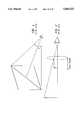
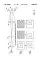
- FIG. 1A real image electronic display is shown in FIG. 1.
- the image viewed by the useris an image created on or projected onto a display surface.
- the size of the display surfacelimits the size of the image that can be provided to the user.
- Miniaturized electronic devicesbecause of their compact size, have limited space for a display surface and therefore are only able to accommodate a relatively small display image.
- a relatively small display imagecreates a series of problems for the person viewing the image.
- the human eyeis only able to resolve a limited amount of detail in an image. Two objects can be resolved by the eye as separate objects only when they are separated by a certain minimum angle as measured from the eye.
- the unaided human eyecan resolve objects with an angle of separation of approximately 1-2 arc minutes or more.
- the human eyealso has difficulty focusing on source objects at very short distances from the eye without causing eye strain.
- the near point for the unaided human eyeis defined as the closest distance that the eye can focus on an object without causing eye strain.
- the near point for the unaided human eyeis about 25 cm for an average middle aged adult. The near point is much longer for an older adult and can be as long as 100 cm.
- the display surface of a real image electronic displayis comprised of an array of small objects, called pixels, which form a real image on the display surface.
- pixelswhich form a real image on the display surface.
- the resolution of the unaided human eye and the near point of the eyedetermine the minimum pixel size that the unaided human eye can resolve.
- the minimum separation between pixels that can be resolved by the unaided eyeis about 75 ⁇ 10 -4 cm, or 75 microns.
- the minimum separation between the pixelsis preferably larger than the minimum resolvable pixel size.
- the human eyedetermines the utility of an electronic display is the eye's angular field of view of an image.
- the eyecan see over a field of view of up to 100 degrees. However, beyond 10-15 degrees from the center of the field, the resolution degrades significantly.
- a comfortable field of view for normal electronic display surfacesis typically in the range of 20-40 degrees.
- the field of viewis defined as the ratio between the largest dimension of the display surface and the distance from the eye to the display.
- An example of a display surface with such a field of viewwould be a TV screen with a 100 cm diagonal viewed at 150 cm.
- the human eyecompensates for the lower resolution at the edges of the display surface by scanning the eye across the display. The scanning of the eye is called eye roll.
- the eye rollmoves the pupil of the eye.
- the typical distance for the motion of the pupil of an adultis about 1 cm.
- An optical systemcan produce both real and virtual images.
- electronic displays providing real imageswere discussed above.
- a real imageexists at a given location when, if a viewing surface is positioned at this location, a real image can be observed by the unaided eye.
- a virtual imageis an image which, if a viewing surface were positioned at the location of the virtual image, no image would be observed by the eye.
- An example of a virtual imageis the image of fine print viewed through a magnifying glass. The print not only appears larger, it also appears to be located substantially behind the surface where the print actually exists.
- a virtual imagecan exist at a location where no display surface exists. The size of the virtual image therefore is not limited by the size of a display surface.
- Virtual image electronic displaysthus have the advantage of eliminating the need for a large display surface in order to produce a large electronic image.
- a virtual image electronic displaymust initially form a source object which is then imaged by an optical system to create the virtual image.
- a substantial advantage of a virtual image electronic displayis that the source object initially created may be as small as can be usefully reimaged by the optical system.
- virtual image electronic displaysmay effectively utilize very small microdisplays to form the source object. Pixel sizes may be as small as a few microns in diameter, a size which the unaided eye cannot resolve. Rather, in order to view the source object formed by the microdisplay, substantial magnification of the optical system is required.
- a virtual imagemust be created by an optical system of some kind. In a real image electronic display, it is the eye and the viewing surface properties which determine the viewing parameters. By contrast, in a virtual image display, the optical system determines most of the viewing parameters.
- the first parameteris the range of distances from the eye which the optical system can be held and have the eye still see the entire virtual image.
- the second parameteris the apparent angular width of the virtual image which is commonly referred to as the field of view of the virtual image.
- the field of viewis defined as the ratio of the apparent width of the virtual image to the apparent distance to the virtual image and is equivalent to the field of view for a real image display surface.
- the third parameteris the transverse distance that the eye may move with respect to the optical system and still have the eye see the entire virtual image through the optical system.
- a simple magnifying lensis shown in FIG. 2.
- the function of a magnifying lensis to provide an image of a nearby object that is larger than the image seen by the unaided eye.
- the objectis placed a distance from then simple lens that is less than the focal length of the lens.
- the eyeobserves a virtual image through the magnifying lens which is larger than the object itself.
- a simple magnifying lenscan magnify a real display surface to produce a virtual image that is significantly larger that the real display.
- the apparent location of the imageis very far away. As a result, the eye is able to view the virtual image in a very relaxed state, thereby minimizing the creation of eye strain on the user.
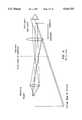
- the far point of a lensrefers to the longest distance that the eye can be held from a magnifying lens and still see the entire virtual image. As illustrated in FIG. 3, the far point is related to the field of view of the virtual image, the eye roll, and the diameter of the optic. The far point increases as the diameter of the optic increases. Optical devices which provide a far point which is a short distance from the optic are undesirable due to the inconvenience and discomfort associated with placing the eye in close proximity with the optic. It is therefore preferred that an optic provide a long far point in order to enable the magnified image to be viewed through the optic at a comfortable and convenient range of distances from the optic.
- the maximum diameter that the optic can haveis related to the magnification of the optic.
- the focal length of the opticIn order to increase the magnification of an optic, the focal length of the optic must be decreased. According to simple lens physics, the maximum diameter that a simple optic can have is approximately equal to the focal length of the optic. Thus, in order to increase the magnification of an optic, the focal length of the optic must be reduced. This reduces the maximum diameter that the optic can have which, in turn, reduces the maximum eye relief provided by the optic.
- the magnification of a simple lensis increased and the diameter of the optic is reduced, the amount of translational movement that the eye can have relative to the magnifying lens while still being able to see the image is reduced. Combined, these factors serve to limit the degree of magnification that a simple magnifying lens can provide.
- users with eye glassesgenerally require an eye relief of at least 25 mm. It is thus preferred that an electronic display provide an eye relief of at least about 25 mm.
- a simple 10 ⁇ magnifying lensgenerally has a focal length of about 25 mm.
- the eye relief provided by a 10 ⁇ magnifier viewing a virtual image with 40 degree field of viewis about 25 mm. Since eye relief decreases as the magnification of an optic increases, magnifying lenses that provide greater than 10 ⁇ magnification are not useful for providing eye relief of at least about 25 mm.
- a compound microscopeis depicted in FIG. 4.
- the simplest compound microscopeis an optical system with two magnifying optics.
- the lens closest to the eyeis referred to as the eyepiece.
- the lens closest to the source objectis called the objective.
- the objectiveforms a real inverted, and usually magnified image of the object. This real image resides in space on the focal plane of the eyepiece.
- the eyepiecemagnifies this real image even further.
- Compound microscopeshave the advantage of providing a higher magnification of nearby objects than can be achieved using a simple magnifying lens.
- the exit pupil of the compound microscopeis defined as the transverse distance across the eyepiece where the entire image of the source object is still visible.
- the exit pupil of the compound microscopeis defined as the transverse distance across the eyepiece where the entire image of the source object is still visible.
- the light rays from some part of the objectare blocked by the optical system and the virtual image is vignetted.
- the light rays from the edge of the objectmust also intersect the pupil of the eye. If the eye is too close to the eyepiece, the edge of the object no longer appears illuminated since the light rays from the edge of the object are blocked by the optical system and the virtual image is vignetted.
- the eyepointThe point where the entire virtual image is visible in the compound microscope is called the eyepoint.
- the distance from the eyepoint to the eyepieceis commonly referred to as the eye relief and is equivalent to the far point of a simple magnifying lens.
- the volume of space around the eyepoint where the image is still visibleis restricted by the optical system, and as a result, the functional volume of space within which the user's eye can be placed is greatly limited in a compound microscope. Given the limited functional volume provided by a compound magnification system, it is generally necessary to move the compound microscope to compensate for the user's eye movements. This greatly limits the functional utility of the compound microscope in viewing systems for electronic displays.
- a synthesized virtual image electronic displayincludes a microdisplay for forming a source object which preferably has a surface area less than about 100 mm 2 , a first stage magnification optic for magnifying the source object to produce a magnified real image, an image synthesizing optic upon which the magnified real image is projected, and a second stage magnification optic for providing a magnified virtual image of the magnified real image projected on the synthesizing optic.
- the image synthesizing opticprovides the synthesized display of the present invention with significant optical and ergonomic advantages over that which can be achieved using prior art simple magnification and compound magnification systems.
- the synthesized displayis intended as an inexpensive component which may be incorporated into any electronic device in which an electronic display is needed.
- the two stages of magnification optics and intermediate image synthesizing optic used in the synthesized displayprovide the significant advantage of enabling the synthesized display to be positioned within a small volume. It is preferred that the synthesized display be positioned within a volume of less than about 375 cubic centimeters, more preferably within a volume of less than about 94 cubic centimeters.
- first and second stage magnification opticsprovide a combined magnification of at least about 20, more preferably at least about 40. It is also preferred that the first stage magnification optic provide a magnification of between about 3 and 10 and a focal length of between about 3.5 and 37.5 mm. It is also preferred that the second stage magnification optic provide a magnification of between about 4 and 7 and an eye relief equal to or greater than about 15 mm, more preferably equal to or greater than about 35 mm, most preferably equal to or greater than about 50 mm.
- FIG. 1illustrates the field of view of a prior art real image electronic display.
- FIG. 2illustrates a prior art simple magnifying lens optical system.
- FIG. 3illustrates how the far point of a prior art simple magnifying lens optical system is related to the field of view of a virtual image, eye roll, and the diameter of the optic.
- FIG. 4illustrates a prior art compound microscope.
- FIG. 5illustrates an embodiment of the synthesized display of the present invention in which a transmissive image synthesizing optic is employed.
- FIG. 6illustrates a second embodiment of the synthesized display of the present invention in which a reflective image synthesizing optic is employed.
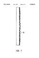
- FIG. 7illustrates a suitable light scattering image synthesizing optic in which a series of micro lenses on the order of 5-10 microns in diameter are used to form small focal length positive and negative lenses.
- FIG. 8illustrates a diffusive image synthesizing optic including an opaque barrier separating individual pixels to prevent light from one pixel from being scattered by secondary scatter into a neighboring pixel.
- FIG. 9illustrates two alternate types of apertures that may be used in the synthesized display of the present invention in which FIG. 9a illustrates an aperture designed to prevent light other than light constituting the image from reaching the image synthesizing optic and FIG. 9b illustrates an aperture as a stop that prevents non-deflected light from passing though the aperture.
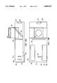
- FIG. 10illustrates the incorporation of a synthesized display into an electronic device in which FIG. 10a illustrates a cross-sectional view of the device and FIG. 10b illustrates a top view of the device.
- FIG. 11illustrates the user's field of view with and without an intermediate image synthesizing optic.
- the present inventionrelates to an inexpensive synthesized virtual image electronic display which provides a magnified virtual image of a source object formed by a microdisplay using two stages of magnification optics and an intermediate image synthesizing optic.
- the source object formed by the microdisplaymust be sufficiently magnified to enable a user's eye to resolve the magnified image.
- the synthesized virtual image electronic display of the present inventionhereinafter referred to as the synthesized display magnifies the source object formed by a microdisplay using a compound magnification system which is comprised of two stages of magnification optics.
- a first stage magnification opticprovides a real image of the source object formed by the microdisplay which is magnified and located in the focal plane of the second stage magnification optic.
- the second stage magnification opticthen provides a further magnified virtual image to be viewed by the eye of the user.
- the synthesized displayalso employs an image synthesizing optic positioned between the first and second stage magnification optics in the focal plane of the second stage magnification optics.
- the synthesizing opticprovides a synthesis function of the real image from the first stage magnification optics. Because the real image produced by the first magnification optic is located on the image synthesizing optic, an image of each pixel is located on that optic, each pixel being represented in that image as either the presence or absence of light from the object as magnified by the first magnification optics.
- the light from each pixelrepresents the real image of that pixel and has a well defined cone angle and a well defined central ray of that cone, such cone angle and central ray being determined by the corresponding object pixel location and by the first stage magnification optics.
- the image synthesizing opticserves to alter the direction of the central ray and alter the cone angle and the shape of the cone to provide enhanced properties to the virtual image provided by the second stage magnification optics.
- the size of the components and spacing between the components employed in the synthesized display of the present inventionis reduced such that the display can be positioned within a small volume.
- the synthesized displayis preferably positionable within a volume of less than about 375 cubic centimeters, most preferably less than about 94 cubic centimeters. These volumes respectively correspond to the volume created by a 100 mm and 25 mm thick electronic device employing an approximately 50 ⁇ 75 mm PCMCIA card.
- the use of two stages of magnification optics in combination with an intermediate image synthesizing opticprovides the synthesized display with enhanced eye relief and a wider field of view than is possible using a traditional compound microscope system.
- the synthesized displayenables the user to view the display over a 30 degree full angle field of view with at least about a 25 mm eye relief.
- the synthesized display of the present inventionis intended as an inexpensive electronic component which may be incorporated into any electronic device in which an electronic display is used.
- the synthesized displayis designed for pocket-sized electronic devices. Examples of such devices include, but are not limited to, portable computers, personal communicators, personal digital assistants, modems, pagers, video and camera viewfinders, mobile phones, television monitors and other hand held devices.
- the synthesized displaypreferably provides a magnified virtual image of a source object that has been magnified by a factor of at least about 20, most preferably by a factor of at least about 40.
- the source objectpreferably has a surface area equal to or less than about 100 mm 2 , most preferably equal to or less than about 25 mm 2 . It should be noted, however, that the present invention can be readily applied to magnifications less than 20 and to microdisplays that form source objects larger than 100 mm 2 .
- the synthesized displaypreferably provides an eye relief equal to or greater than about 15 mm, more preferably equal to or greater than about 35 mm, most preferably equal to or greater than about 50 mm.
- the synthesized displayalso preferably provides an image which is at least equivalent in size to a computer monitor (24 cm ⁇ 18 cm) when viewed at 50 cm. This size is roughly equivalent to a large screen TV (100 cm diagonal) when viewed at 165 cm.
- the synthesized displayincludes a microdisplay 12 which forms a source object 14.
- the microdisplaymay be any electronically activated display which produces an image of any type.
- the microdisplaymay be a liquid crystal display, a CRT, a spatial light modulator, a grating, a mirror light valve or a LED array.
- the microdisplayis frequently the most expensive component of the synthesized display. It is therefore preferred that the size of the microdisplay be minimized.
- the microdisplaypreferably has a surface area equal to or less than about 100 mm 2 , most preferably equal to or less than about 25 mm 2 . However, it should be understood that larger microdisplays may be employed in the present invention. It is also preferred that the microdisplay 12 form a source object 14 using an array of pixels 11 on the microdisplay 12 wherein each pixel has an area equal to or less than about 400 square microns, more preferably 100 square microns.
- the microdisplay used to form the source objectis a spatial light modulator.
- Spatial light modulatorsalso known as light valves, are well known in the art for use in electronic display systems.
- a spatial light modulatorincludes an addressable array of light modulating mirror elements which modulate incident light in a spatial pattern to produce an image.
- the array of modulating elementsare modulated in response to an electrical or optical input where each light modulating element corresponds to a pixel of the image generated by the light modulator.
- Incident lightmay be modulated by the modulating elements with regard to phase, intensity, polarization, or direction.
- Light modulationmay be achieved using a variety of materials exhibiting electrooptic or magnetooptic effects and by materials that modulate light by surface deformation.
- the source object 14 formed by the microdisplay 12is magnified by a first stage magnification optic 18 to produce a magnified virtual image.
- the first stage magnification optic 18serves to reduce the degree of magnification required of the second stage magnification optic and thus provides a magnification greater than 1.
- the first stage magnification opticpreferably provides a magnification greater than 3, most preferably between about 3 and 10.
- the first stage magnification optic 18also preferably has an effective focal length between about 3.5 mm and 37.5 mm.
- the magnified virtual image produced by the first stage magnification opticis projected on to a image synthesizing optic 24 to produce a magnified real image 26.
- the light path between the first stage magnification optic 18 and the image synthesizing optic 24is referred to as the first distance 22.
- the first distance 22is preferably between about 35 and 150 mm.
- the upper limit of 150 mmcorresponds to twice the preferred length of the container within which the synthesized display is contained. It should be noted, however, that larger containers may be employed and thus larger first distances 22 may be used.
- the image synthesizing optic 24may be any device which produces a directly viewable image when placed in the real image plane of a magnification optic.
- the image synthesizing opticmay be a light transmissive image synthesizing optic where the source object is imaged on to the rear surface 28 of the image synthesizing optic 24 to produce a magnified real image 26.
- the magnified real image 26may be projected on to a reflective image synthesizing optic 30.
- the same reference numeralsare employed with regard to FIG. 6 as are employed in FIG. 5.
- the image synthesizing optic 24is preferably designed such that a large fraction of the light is redirected so that the entirety of the image remains visible as the eye is moved laterally relative to the second stage magnification optic.
- the numerical aperture of the directed lightis preferably on the order of the (radius of the second stage magnification optic)/(focal length of the second stage magnification optic).
- the image synthesizing opticshould redirect the central ray of the cone of light from each point on the image synthesizing optic to the center of the second magnification optic.
- a suitable light redirecting image synthesizing opticis illustrated in FIG.
- a series of micro lenses 33 on the order of 5-10 microns in diameterare used to form small focal length positive or negative lenses.
- the outputs of the micro lensesmay be tilted to direct a large fraction of the light towards the eyepiece.
- the image synthesizing optic 24be designed to alias the magnified real image 26.
- the image synthesizing opticshould be transparent.
- the image synthesizing opticcan be diffuse such that light is scattered as the light passes throughout the diffusing material.
- the diffusive scatterperforms the function of modifying the numerical aperture of the light.
- suitable light diffusing image synthesizing optic materialsinclude ground glass, opal glass, holographic diffusers, thin diffusive plastics such as polystyrene and molded plastic with diffusing surfaces.
- the diffusive materialshould be thinner than the size of the pixels projected onto the image synthesizing optic to prevent secondary scattering of the light within the diffusive material into neighboring pixels, thereby blurring the pixels.
- Pixel blurring due to secondary scattermay be overcome using an array of pixels formed of a diffusive material as illustrated in FIG. 8.
- the diffusive image synthesizing opticis composed of an array of individual pixels 43 where each pixel is separated by opaque barrier 45 which prevents light from one pixel from being scattered by secondary scatter into a neighboring pixel.
- the opaque barrier 45is preferably reflective but may also form a light absorbing barrier.
- the magnified real image 26 projected onto the image synthesizing optic 24is conveyed along a second distance 34 to a second stage magnification optic 36 which magnifies the magnified real image 26 to produce a magnified virtual image 38 which is seen by the user 40.
- the second distance 34is approximately equal to the focal length of the second stage magnification optic 36.
- the second stage magnification optic 36is used to provide the user 40 with a magnified virtual image 38. It is preferred that the eye relief provided by the second stage magnification optic 36 be equal to or greater than about 15 mm, more preferably equal to or greater than about 35 mm, most preferably equal to or greater than about 50 mm.
- the second stage magnification opticpreferably provides magnification by a factor of at least about 4, more preferably by a factor between about 4 and 7.
- the first and second stage magnification optics 18, 36combine to magnify the source object formed by the microdisplay by a factor equal to or greater than about 20, more preferably equal to or greater than a factor of about 40.
- the synthesized display of the present inventionis able to employ smaller components and a more compact layout than is possible using one magnification stage corresponding to a projection system, thereby enabling the synthesized display to be positioned within a compact container.
- the first and second stage magnification optics 18, 38can have shorter diameters 42, 44 than would be required to magnify the object in a single stage.
- the distance 22 between the first stage magnification optic 18 and the image synthesizing optic 24 and the distance 34 between the second stage magnification optic 38 and the image synthesizing optic 24are also shorter than would be required to produce the same degree of magnification in a single stage.
- the degree of magnification needed in the second stageis reduced which, in turn, provides the user with a wider field of view and longer eye relief than compared to high power magnifying lens.
- the second stage magnification opticcan be focused at a point near infinity which reduces the amount of eye strain caused when the user focuses his or her eyes on the synthesized display.
- the microdisplay used to form the source objectis a spatial light modulator
- an illumination source and a light apertureare generally needed to form the source object.
- An illumination sourceis needed since the source object formed by a spatial light modulator microdisplay is based on light from the illumination source that is either deflected or non-deflected by the microdisplay. In general, it is preferred that the source object be formed based on non-deflected light which provides a brighter image due to less light loss from reflection off of the array of addressable mirror elements.
- the illumination source used to illuminate the microdisplaymay be positioned such that illumination is provided off-axis relative to the light path of the image reflected off of the surface of the microdisplay. Off-axis illumination of the microdisplay is preferred in view of the light efficiency provided. Alternatively, illumination from the illumination source may be provided on-axis relative to the light path of the image reflected off of the surface of the microdisplay. When on-axis illumination is employed, a beamsplitter or other mechanism for distinguishing illumination light from light reflected off of the microdisplay is needed. The reflectance of the beamsplitter may be between about 20 and 80%, most preferably 50%.
- Beamsplittershave the disadvantage of only transmitting a small percentage of the light reflected off of the surface of the microdisplay, generally about 25%. As a result, systems using a beamsplitter generally provide a dimmer image than off-axis systems. It is also preferred that an illumination lens be positioned between the microdisplay and the illumination source to shape the light from the illumination source upon the array of addressable mirror elements on the surface of the microdisplay.
- a quarter-waveplate and polarizermay be used as an alternative to a beamsplitter.
- the polarizermay be any device that preferably reflects one component of the light polarization.
- the polarizeris preferably a traditional calcite polarizer, a dielectrically coated cube, or a dielectric coated surface.
- the waveplatemay be any device that produces approximately a quarter wave of phase lag between orthogonal polarization components.
- the waveplateis preferably a quartz quarter-waveplate.
- a polarized light sourcesuch as a laser, is preferably used.
- FIG. 9illustrates two types of light apertures that may be used in the present invention.
- the aperture 47 illustrated in FIG. 9ais designed to prevent light other than light constituting the image from reaching the image synthesizing optic by preventing the deflected light from passing though the aperture.
- the aperturemay be a stop 49 that prevents non-deflected light from passing though the aperture. It should be noted, however, that any light aperture may be adapted for use in the present invention. Examples of other suitable apertures include, but are not limited to, phase plates and spatial filters.
- the synthesized display of the present inventionis intended as a component which may be incorporated into any electronic device.
- the incorporation of the synthesized display into an electronic deviceis illustrated in FIG. 10.
- FIG. 10aillustrates a cross-sectional view of the device.
- Reference numerals 46, 48, 50 and 52refer to the top, side and first and second ends of the device respectively.
- the synthesized display employed in FIG. 10has the same general layout as is illustrated in FIG. 5.
- the same reference numeralsare employed with regard to FIG. 10 as are employed in FIG. 5 with the exception of the magnification optics.
- the synthesized display of the electronic deviceincludes two different second stage magnification optics 54, 56 which may be employed by the user as alternative viewing lenses.
- one of the second stage magnification optics 54is positioned on an end 50 of the device.
- the second stage magnification optic 56is positioned on the top 46 of the device.
- the surface area on the top of the deviceis larger than the other surfaces of the device.
- the top 46can accommodate a larger sized optic than the other surfaces.
- FIG. 10aillustrates an embodiment of the present invention in which the user is able to select which second stage magnification optic 54, 56 to employ as a viewing lens.
- second stage magnification optic 56is attached to an extendible and retractable viewing assembly 58.
- a moveable mirror 60rotates into the path between the image synthesizing optic 30 and second stage magnification optic 54, thereby diverting the image to second stage magnification optic 56.
- FIG. 10billustrates the electronics 60, 62 included within the device.
- Electronic 62serves as an input device for microdisplay 12 and is electronically attached to the microdisplay 12 by input 13.
- the input deviceprovides the microdisplay 12 with an electrical signal from which the microdisplay 12 produces an electronically formed source object.
- Table 1provides three examples of synthesized virtual image systems. All examples use the same sized microdisplay and provide the same degree of magnification and eye relief.
- the second and third examplesprovide no magnification in the first and second magnification stage respectively. As a result, the second and third examples reflect a single stage magnification system which provides a real image and a virtual image respectively.
- the 240 ⁇ 240 mm 2 image synthesizing optic required in the single stage real image electronic displaylimits the degree to which the display may be miniaturized.
- the image synthesizing optic 24is employed to provide an real image to the user 40.
- the screenmust be a factor of Y 2 larger than the image synthesizing optic employed in the two stage magnification system in order to provide the user with an equivalently magnified image.
- the first distance 22must be increased in order for the first stage magnification optic 18 to achieve a factor of Y 2 greater magnification.
- the electronic displaybecomes analogous to a compound microscope.
- the user's eyeIn a compound microscope, the user's eye must be in the direct line of site of the source object being magnified. Slight lateral movement of the eye relative to the second stage magnification optic causes the image to no longer be visible.
Landscapes
- Physics & Mathematics (AREA)
- General Physics & Mathematics (AREA)
- Optics & Photonics (AREA)
Abstract
Description
TABLE 1 __________________________________________________________________________ Second Distances First Stage Stage 1st 2nd User Micro- Magnification Synthesizing Magnification Magn. Magn. Con- Electronic Display Overall Optic Optic Optic Optic Optic venience Display Size Magn. Magn. Focal Surface Magn. Focal And And Total Eye Type (Diagonal) Z = Y.sub.1 *Y.sub.2 Y.sub.1 Length Area Y.sub.2 Length Screen Screen Distance Relief __________________________________________________________________________Synthesized 5mm 48× 8× 5mm 40 × 40 mm 6× 41.6mm 45 mm 41.6 mm 86.6 80 mm Two Stage Single 5mm 48× 48× 5 mm 240 × 240 mm 1× N.A. 240 mm N.A. 240 Infinite Stage, Real Image Single 5mm 48× 1× N.A. 5 × 5mm 48× 5 mm N.A. 5 mm 5 5 mm Stage, Virtual Image __________________________________________________________________________ *N.A. = Not applicable.
Claims (32)
Priority Applications (14)
| Application Number | Priority Date | Filing Date | Title |
|---|---|---|---|
| US08/361,035US5644323A (en) | 1994-12-21 | 1994-12-21 | Miniature synthesized virtual image electronic display |
| US08/407,102US5625372A (en) | 1994-12-21 | 1995-03-17 | Compact compound magnified virtual image electronic display |
| US08/441,529US5684497A (en) | 1994-12-21 | 1995-05-15 | Twice folded compound magnified virtual image electronic display |
| AT95944160TATE182691T1 (en) | 1994-12-21 | 1995-12-20 | ELECTRONIC DISPLAY DEVICE WITH COMPOUND ENLARGED VIRTUAL IMAGES |
| AU46032/96AAU4603296A (en) | 1994-12-21 | 1995-12-20 | Compound magnified virtual image electronic display |
| JP51996696AJP3206920B2 (en) | 1994-12-21 | 1995-12-20 | Compact electronic display system |
| DE69511114TDE69511114D1 (en) | 1994-12-21 | 1995-12-20 | ELECTRONIC DISPLAY DEVICE WITH "COMPOUND" ENLARGED VIRTUAL IMAGES |
| EP95944160AEP0799435B1 (en) | 1994-12-21 | 1995-12-20 | Compound magnified virtual image electronic display |
| PCT/US1995/016598WO1996019746A2 (en) | 1994-12-21 | 1995-12-20 | Compound magnified virtual image electronic display |
| US08/775,840US5838498A (en) | 1994-12-21 | 1996-12-31 | Miniature synthesized virtual image electronic display |
| US08/831,106US5870068A (en) | 1994-12-21 | 1997-04-01 | Twice folded compound magnified virtual image electronic display |
| US08/831,371US5905478A (en) | 1994-12-21 | 1997-04-01 | Twice folded compound magnified virtual image electronic display |
| US09/182,952US5973845A (en) | 1994-12-21 | 1998-10-29 | Miniature synthesized virtual image electronic display |
| US09/182,951US6603443B1 (en) | 1994-12-21 | 1998-10-29 | Compact display system controlled by eye position sensory system |
Applications Claiming Priority (1)
| Application Number | Priority Date | Filing Date | Title |
|---|---|---|---|
| US08/361,035US5644323A (en) | 1994-12-21 | 1994-12-21 | Miniature synthesized virtual image electronic display |
Related Child Applications (2)
| Application Number | Title | Priority Date | Filing Date |
|---|---|---|---|
| US08/407,102Continuation-In-PartUS5625372A (en) | 1994-12-21 | 1995-03-17 | Compact compound magnified virtual image electronic display |
| US08/775,840ContinuationUS5838498A (en) | 1994-12-21 | 1996-12-31 | Miniature synthesized virtual image electronic display |
Publications (1)
| Publication Number | Publication Date |
|---|---|
| US5644323Atrue US5644323A (en) | 1997-07-01 |
Family
ID=23420392
Family Applications (3)
| Application Number | Title | Priority Date | Filing Date |
|---|---|---|---|
| US08/361,035Expired - LifetimeUS5644323A (en) | 1994-12-21 | 1994-12-21 | Miniature synthesized virtual image electronic display |
| US08/775,840Expired - LifetimeUS5838498A (en) | 1994-12-21 | 1996-12-31 | Miniature synthesized virtual image electronic display |
| US09/182,952Expired - LifetimeUS5973845A (en) | 1994-12-21 | 1998-10-29 | Miniature synthesized virtual image electronic display |
Family Applications After (2)
| Application Number | Title | Priority Date | Filing Date |
|---|---|---|---|
| US08/775,840Expired - LifetimeUS5838498A (en) | 1994-12-21 | 1996-12-31 | Miniature synthesized virtual image electronic display |
| US09/182,952Expired - LifetimeUS5973845A (en) | 1994-12-21 | 1998-10-29 | Miniature synthesized virtual image electronic display |
Country Status (1)
| Country | Link |
|---|---|
| US (3) | US5644323A (en) |
Cited By (35)
| Publication number | Priority date | Publication date | Assignee | Title |
|---|---|---|---|---|
| US5883606A (en)* | 1995-12-18 | 1999-03-16 | Bell Communications Research, Inc. | Flat virtual displays for virtual reality |
| US5926318A (en)* | 1998-04-06 | 1999-07-20 | Optimize Incorporated | Biocular viewing system with intermediate image planes for an electronic display device |
| US5973845A (en)* | 1994-12-21 | 1999-10-26 | Hildebrand; Alfred P. | Miniature synthesized virtual image electronic display |
| US5984477A (en)* | 1998-05-22 | 1999-11-16 | Cae Electronics Ltd. | Helmet mounted display with improved SLM illumination |
| US6028704A (en)* | 1993-05-17 | 2000-02-22 | Freeman; Robin John | Optical instrument and optical element thereof |
| US6057810A (en)* | 1996-06-20 | 2000-05-02 | Immersive Technologies, Inc. | Method and apparatus for orientation sensing |
| US6072443A (en)* | 1996-03-29 | 2000-06-06 | Texas Instruments Incorporated | Adaptive ocular projection display |
| US6094181A (en)* | 1998-02-02 | 2000-07-25 | Inviso, Inc. | Miniature synthesized virtual image electronic display |
| US6219186B1 (en) | 1998-04-06 | 2001-04-17 | Optimize Incorporated | Compact biocular viewing system for an electronic display |
| US6222675B1 (en) | 1998-12-01 | 2001-04-24 | Kaiser Electro-Optics, Inc. | Area of interest head-mounted display using low resolution, wide angle; high resolution, narrow angle; and see-through views |
| US6222686B1 (en)* | 1999-10-22 | 2001-04-24 | Motorola, Inc. | Gradient index magnifying lens |
| US6246459B1 (en) | 1998-06-10 | 2001-06-12 | Tyco Electronics Corporation | Assembly including an active matrix liquid crystal display module and having plural environmental seals |
| US6396463B1 (en)* | 1998-07-23 | 2002-05-28 | Fuji Xerox Co., Ltd. | Image projection apparatus |
| US6404557B2 (en) | 1999-09-10 | 2002-06-11 | Inviso, Inc. | Display illumination system |
| US20030068057A1 (en)* | 2001-10-06 | 2003-04-10 | Miller Eric C. | Information system using eyewear for communication |
| US20030090439A1 (en)* | 2001-09-07 | 2003-05-15 | Spitzer Mark B. | Light weight, compact, remountable face-supported electronic display |
| US6603443B1 (en)* | 1994-12-21 | 2003-08-05 | Three-Five Systems, Inc. | Compact display system controlled by eye position sensory system |
| US6608720B1 (en) | 1997-06-02 | 2003-08-19 | Robin John Freeman | Optical instrument and optical element thereof |
| US6618099B1 (en) | 1999-06-21 | 2003-09-09 | The Microoptical Corporation | Display device with eyepiece assembly and display on opto-mechanical support |
| GB2387237A (en)* | 2002-04-04 | 2003-10-08 | Hewlett Packard Co | Viewer with screen for near eye viewfinder |
| US6671100B1 (en) | 1999-10-14 | 2003-12-30 | Stratos Product Development Llc | Virtual imaging system |
| US6724354B1 (en)* | 1999-06-21 | 2004-04-20 | The Microoptical Corporation | Illumination systems for eyeglass and facemask display systems |
| US20040150758A1 (en)* | 2002-12-05 | 2004-08-05 | Samsung Electronics Co., Ltd. | Head-mounted display |
| US20050286135A1 (en)* | 2004-02-04 | 2005-12-29 | Paul Weissman | Compact electronic viewfinder |
| US7158096B1 (en) | 1999-06-21 | 2007-01-02 | The Microoptical Corporation | Compact, head-mountable display device with suspended eyepiece assembly |
| US20080048960A1 (en)* | 1996-10-31 | 2008-02-28 | Kopin Corporation | Microdisplay for portable communication systems |
| US20080303285A1 (en)* | 2007-06-11 | 2008-12-11 | Bondhus Troy D | Method and apparatus for hydroelectric power generation |
| US20100053121A1 (en)* | 2008-09-04 | 2010-03-04 | Randall Sprague | System and apparatus for deflection optics |
| US20100053030A1 (en)* | 2008-09-04 | 2010-03-04 | Sprague Randall B | Method and apparatus to process display and non-display information |
| US20100053549A1 (en)* | 2008-09-04 | 2010-03-04 | Jerome Legerton | Method and apparatus for constructing a contact lens with optics |
| US20100149618A1 (en)* | 2008-09-04 | 2010-06-17 | Randall Sprague | System and apparatus for pixel matrix see-through display panels |
| US20100265163A1 (en)* | 2008-09-04 | 2010-10-21 | Jerome Legerton | System and apparatus for display panels |
| US8922898B2 (en) | 2008-09-04 | 2014-12-30 | Innovega Inc. | Molded lens with nanofilaments and related methods |
| WO2016115562A1 (en)* | 2015-01-16 | 2016-07-21 | Valve Corporation | Low f/# lens |
| US10509230B2 (en)* | 2017-09-28 | 2019-12-17 | Seiko Epson Corporation | Virtual display apparatus |
Families Citing this family (17)
| Publication number | Priority date | Publication date | Assignee | Title |
|---|---|---|---|---|
| US6204974B1 (en) | 1996-10-08 | 2001-03-20 | The Microoptical Corporation | Compact image display system for eyeglasses or other head-borne frames |
| JPH10282448A (en)* | 1997-04-04 | 1998-10-23 | Minolta Co Ltd | Display |
| CA2307877C (en) | 1997-10-30 | 2005-08-30 | The Microoptical Corporation | Eyeglass interface system |
| WO2000028370A1 (en)* | 1998-11-06 | 2000-05-18 | Kopin Corporation | Microdisplay viewer |
| HK1046036A1 (en) | 1999-06-21 | 2002-12-20 | The Microoptical Corporation | Eyeglass display lens system employing off-axis optical design |
| AU2001255360A1 (en)* | 2000-04-14 | 2001-10-30 | C-360, Inc. | Illuminated viewing assembly, viewing system including the illuminated viewing assembly, and method of viewing therefor |
| FR2815422B1 (en)* | 2000-10-13 | 2003-09-19 | Commissariat Energie Atomique | INDIVIDUAL VISUALIZATION SYSTEM |
| US6688748B2 (en)* | 2001-01-12 | 2004-02-10 | Aurora Systems, Inc. | System and method for using off-axis illumination in a reflective projection system |
| US6953249B1 (en) | 2001-01-29 | 2005-10-11 | Maguire Jr Francis J | Method and devices for displaying images for viewing with varying accommodation |
| US6844980B2 (en)* | 2001-04-23 | 2005-01-18 | Reveo, Inc. | Image display system and electrically actuatable image combiner therefor |
| US6972735B2 (en)* | 2002-03-20 | 2005-12-06 | Raymond T. Hebert | Head-mounted viewing system for single electronic displays using biocular lens with binocular folding mirrors |
| GB0223119D0 (en)* | 2002-10-05 | 2002-11-13 | Holographic Imaging Llc | Reconfigurable spatial light modulators |
| DE10311306A1 (en)* | 2003-03-14 | 2004-09-23 | Carl Zeiss | Image display device, e.g. head-mounted display device, has pupil optics that spatially magnify outlet pupil of imaging optics and/or move outlet pupil of imaging optics |
| GB0310654D0 (en)* | 2003-05-09 | 2003-06-11 | Koninkl Philips Electronics Nv | Mirror assembly with integrated display device |
| GB0310655D0 (en)* | 2003-05-09 | 2003-06-11 | Koninkl Philips Electronics Nv | Virtual display |
| US7876583B2 (en)* | 2008-12-22 | 2011-01-25 | Power Integrations, Inc. | Flyback power supply with forced primary regulation |
| US9599757B2 (en) | 2014-10-10 | 2017-03-21 | Microsoft Technology Licensing, Llc | Increased accuracy corner cube arrays for high resolution retro-reflective imaging applications |
Citations (17)
| Publication number | Priority date | Publication date | Assignee | Title |
|---|---|---|---|---|
| GB2004383A (en)* | 1977-08-29 | 1979-03-28 | Farrand Optical Co Inc | Infinity display system |
| GB2182456A (en)* | 1983-09-13 | 1987-05-13 | Secr Defence | Display systems |
| US4859031A (en)* | 1987-08-03 | 1989-08-22 | Kaiser Electronics | Optical collimating apparatus |
| EP0351967A2 (en)* | 1988-07-06 | 1990-01-24 | Kaiser Aerospace And Electronics Corporation | Improved optical combiner collimating apparatus |
| US4900133A (en)* | 1988-10-27 | 1990-02-13 | Kaiser Electronics | Heads-up display combiner utilizing a cholesteric liquid crystal element |
| US5087116A (en)* | 1990-07-27 | 1992-02-11 | Eastman Kodak Company | Reflective image display including a first mirror and a Fresnel mirror |
| US5157503A (en)* | 1991-07-16 | 1992-10-20 | Hughes Aircraft Company | Near-infinity image display system |
| EP0566002A1 (en)* | 1992-04-07 | 1993-10-20 | Hughes Aircraft Company | Ultra-compact, wide field of view virtual image display optical system |
| EP0566000A1 (en)* | 1992-04-07 | 1993-10-20 | Hughes Aircraft Company | Virtual image display system |
| EP0566001A2 (en)* | 1992-04-07 | 1993-10-20 | Hughes Aircraft Company | Wide spectral bandwidth virtual image display optical system |
| US5291338A (en)* | 1989-06-15 | 1994-03-01 | Jaeger | Head-down type optical device for delivering information to the driver of a motor vehicle |
| US5369415A (en)* | 1992-06-29 | 1994-11-29 | Motorola, Inc. | Direct retinal scan display with planar imager |
| US5467104A (en)* | 1992-10-22 | 1995-11-14 | Board Of Regents Of The University Of Washington | Virtual retinal display |
| US5467215A (en)* | 1994-12-21 | 1995-11-14 | Motorola | Integrated electro-optic package for reflective spatial light modulators |
| US5486946A (en)* | 1994-12-21 | 1996-01-23 | Motorola | Integrated electro-optic package for reflective spatial light modulators |
| US5491491A (en)* | 1994-10-31 | 1996-02-13 | Motorola | Portable electronic equipment with binocular virtual display |
| US5499138A (en)* | 1992-05-26 | 1996-03-12 | Olympus Optical Co., Ltd. | Image display apparatus |
Family Cites Families (67)
| Publication number | Priority date | Publication date | Assignee | Title |
|---|---|---|---|---|
| US3296509A (en)* | 1965-11-12 | 1967-01-03 | Gen Electric | Capacitor with polyphenylene oxide dielectric |
| US3758196A (en)* | 1971-04-12 | 1973-09-11 | H Weiss | Optical magnifying system and apparatus for viewing small objects |
| US4099831A (en)* | 1971-11-29 | 1978-07-11 | Vision Engineering, Ltd. | High magnification optical apparatus with rotatable reflective lenticulated surface |
| US4082432A (en)* | 1975-01-09 | 1978-04-04 | Sundstrand Data Control, Inc. | Head-up visual display system using on-axis optics with image window at the focal plane of the collimating mirror |
| US4082440A (en)* | 1975-10-14 | 1978-04-04 | Gaf Corporation | Compact microform reader |
| US4361384A (en)* | 1980-06-27 | 1982-11-30 | The United States Of America As Represented By The Secretary Of The Army | High luminance miniature display |
| US4339188A (en)* | 1981-03-23 | 1982-07-13 | Beattie Systems, Inc. | Bright screen optical viewer apparatus and method |
| US5035474A (en)* | 1984-04-16 | 1991-07-30 | Hughes Aircraft Company | Biocular holographic helmet mounted display |
| JPS61188236A (en)* | 1985-02-18 | 1986-08-21 | Nissan Motor Co Ltd | Vehicle display device |
| US4728185A (en)* | 1985-07-03 | 1988-03-01 | Texas Instruments Incorporated | Imaging system |
| US4717248A (en)* | 1985-10-03 | 1988-01-05 | Larussa Joseph | Display system |
| JP2556020B2 (en)* | 1987-02-06 | 1996-11-20 | 日本電装株式会社 | Display device using hologram |
| GB2203855B (en)* | 1987-04-16 | 1990-10-03 | Yazaki Corp | Display apparatus for a vehicle |
| US4925272A (en)* | 1988-02-15 | 1990-05-15 | Yazaki Corporation | Indication display unit for vehicles |
| NL8802517A (en)* | 1988-10-13 | 1990-05-01 | Philips Nv | IMAGE PROJECTION DEVICE. |
| JPH0469850A (en)* | 1990-07-10 | 1992-03-05 | Sony Corp | Position controller for tape recorder |
| US5121099A (en)* | 1990-08-31 | 1992-06-09 | Hughes Aircraft Company | Two-page automotive virtual image display |
| US5189512A (en)* | 1991-07-01 | 1993-02-23 | Camair Research, Inc. | Helmet integrated display system |
| JPH0588079A (en)* | 1991-09-30 | 1993-04-09 | Matsushita Electric Ind Co Ltd | Fourier transform lens and optical information processing device |
| US5224198A (en)* | 1991-09-30 | 1993-06-29 | Motorola, Inc. | Waveguide virtual image display |
| JP2857273B2 (en)* | 1991-12-24 | 1999-02-17 | 科学技術振興事業団 | Aberration correction method and aberration correction device |
| US5361165A (en)* | 1992-01-03 | 1994-11-01 | General Motors Corporation | Reflective cluster display with stowable viewing screen |
| JP2543554Y2 (en)* | 1992-01-14 | 1997-08-06 | 矢崎総業株式会社 | Display device for vehicles |
| US5303085A (en)* | 1992-02-07 | 1994-04-12 | Rallison Richard D | Optically corrected helmet mounted display |
| US5383053A (en)* | 1992-04-07 | 1995-01-17 | Hughes Aircraft Company | Virtual image display having a high efficiency grid beamsplitter |
| US5334991A (en)* | 1992-05-15 | 1994-08-02 | Reflection Technology | Dual image head-mounted display |
| US5323477A (en)* | 1992-08-24 | 1994-06-21 | Motorola, Inc. | Contact array imager with integral waveguide and electronics |
| GB9218628D0 (en)* | 1992-09-03 | 1992-10-21 | Vision Eng | Optical magnifying apparatus |
| JP3379797B2 (en)* | 1992-11-12 | 2003-02-24 | オリンパス光学工業株式会社 | Image display device |
| US5654827A (en)* | 1992-11-26 | 1997-08-05 | Elop Electrooptics Industries Ltd. | Optical system |
| JP3386500B2 (en)* | 1992-12-21 | 2003-03-17 | 大日本印刷株式会社 | Image processing method |
| JPH06194598A (en)* | 1992-12-25 | 1994-07-15 | Olympus Optical Co Ltd | Display device of head mounting type |
| US5418584A (en)* | 1992-12-31 | 1995-05-23 | Honeywell Inc. | Retroreflective array virtual image projection screen |
| US5422653A (en)* | 1993-01-07 | 1995-06-06 | Maguire, Jr.; Francis J. | Passive virtual reality |
| US5537260A (en)* | 1993-01-26 | 1996-07-16 | Svg Lithography Systems, Inc. | Catadioptric optical reduction system with high numerical aperture |
| US5351151A (en)* | 1993-02-01 | 1994-09-27 | Levy George S | Optical filter using microlens arrays |
| US5546227A (en)* | 1993-02-24 | 1996-08-13 | Olympus Optical Co., Ltd. | Image display apparatus |
| US5539578A (en)* | 1993-03-02 | 1996-07-23 | Olympus Optical Co., Ltd. | Image display apparatus |
| US5539422A (en)* | 1993-04-12 | 1996-07-23 | Virtual Vision, Inc. | Head mounted display system |
| JP3245478B2 (en)* | 1993-04-27 | 2002-01-15 | オリンパス光学工業株式会社 | Head mounted display |
| JPH06315125A (en)* | 1993-04-28 | 1994-11-08 | Olympus Optical Co Ltd | Video display device |
| JPH06324285A (en)* | 1993-05-13 | 1994-11-25 | Olympus Optical Co Ltd | Visual display device |
| US5579026A (en)* | 1993-05-14 | 1996-11-26 | Olympus Optical Co., Ltd. | Image display apparatus of head mounted type |
| DE4319904C2 (en)* | 1993-06-16 | 2002-11-28 | Siemens Ag | Warning device for displaying information in a vehicle |
| US5422758A (en)* | 1993-09-08 | 1995-06-06 | Laser Machining, Inc. | Adjustable beam splitter |
| JP3322283B2 (en)* | 1993-09-14 | 2002-09-09 | ソニー株式会社 | Image display device |
| JPH07159719A (en)* | 1993-12-07 | 1995-06-23 | Olympus Optical Co Ltd | Video display device |
| US5638218A (en)* | 1993-12-07 | 1997-06-10 | Nikon Corporation | Catadioptric projection apparatus |
| US5659430A (en)* | 1993-12-21 | 1997-08-19 | Olympus Optical Co., Ltd. | Visual display apparatus |
| JPH07181391A (en)* | 1993-12-22 | 1995-07-21 | Olympus Optical Co Ltd | Image display device |
| JP3089939B2 (en)* | 1994-03-15 | 2000-09-18 | 松下電器産業株式会社 | Fourier transform optical device |
| US5552934A (en)* | 1994-03-18 | 1996-09-03 | Spm Corporation | Background reflection-reducing plano-beam splitter for use in real image projecting system |
| US5612549A (en)* | 1994-03-24 | 1997-03-18 | Motorola | Integrated electro-optical package |
| US5557353A (en)* | 1994-04-22 | 1996-09-17 | Stahl; Thomas D. | Pixel compensated electro-optical display system |
| US5394203A (en)* | 1994-06-06 | 1995-02-28 | Delco Electronics Corporation | Retracting head up display with image position adjustment |
| US5506728A (en)* | 1994-06-10 | 1996-04-09 | Kaiser Aerospace & Electronics Corporation | Dual combiner eyepiece |
| US5457575A (en)* | 1994-06-20 | 1995-10-10 | Delco Electronics Corporation | Retracting head up display with fine adjustment of combiner |
| US5483307A (en)* | 1994-09-29 | 1996-01-09 | Texas Instruments, Inc. | Wide field of view head-mounted display |
| US5485318A (en)* | 1994-10-03 | 1996-01-16 | Motorola, Inc. | Dual image manifestation apparatus with integrated electro-optical package |
| US5572363A (en)* | 1994-11-28 | 1996-11-05 | Fergason; James L. | Retro-reflector based in-line viewing system |
| US5543958A (en)* | 1994-12-21 | 1996-08-06 | Motorola | Integrated electro-optic package for reflective spatial light modulators |
| US5539554A (en)* | 1994-12-21 | 1996-07-23 | Motorola | Integrated electro-optic package for reflective spatial light |
| US5644323A (en)* | 1994-12-21 | 1997-07-01 | Siliscape, Inc. | Miniature synthesized virtual image electronic display |
| US5684497A (en)* | 1994-12-21 | 1997-11-04 | Siliscape, Inc. | Twice folded compound magnified virtual image electronic display |
| US5596451A (en)* | 1995-01-30 | 1997-01-21 | Displaytech, Inc. | Miniature image generator including optics arrangement |
| KR970004783A (en)* | 1995-06-29 | 1997-01-29 | Image Projection Device Using Acousto-optic Tuning Filter | |
| US5771124A (en)* | 1996-07-02 | 1998-06-23 | Siliscape | Compact display system with two stage magnification and immersed beam splitter |
- 1994
- 1994-12-21USUS08/361,035patent/US5644323A/ennot_activeExpired - Lifetime
- 1996
- 1996-12-31USUS08/775,840patent/US5838498A/ennot_activeExpired - Lifetime
- 1998
- 1998-10-29USUS09/182,952patent/US5973845A/ennot_activeExpired - Lifetime
Patent Citations (20)
| Publication number | Priority date | Publication date | Assignee | Title |
|---|---|---|---|---|
| GB2004383A (en)* | 1977-08-29 | 1979-03-28 | Farrand Optical Co Inc | Infinity display system |
| GB2182456A (en)* | 1983-09-13 | 1987-05-13 | Secr Defence | Display systems |
| US4859031A (en)* | 1987-08-03 | 1989-08-22 | Kaiser Electronics | Optical collimating apparatus |
| EP0351967A2 (en)* | 1988-07-06 | 1990-01-24 | Kaiser Aerospace And Electronics Corporation | Improved optical combiner collimating apparatus |
| US5050966A (en)* | 1988-07-06 | 1991-09-24 | Kaiser Aerospace & Electronics Corporation | Optical combiner collimating apparatus |
| US4900133A (en)* | 1988-10-27 | 1990-02-13 | Kaiser Electronics | Heads-up display combiner utilizing a cholesteric liquid crystal element |
| US5291338A (en)* | 1989-06-15 | 1994-03-01 | Jaeger | Head-down type optical device for delivering information to the driver of a motor vehicle |
| US5087116A (en)* | 1990-07-27 | 1992-02-11 | Eastman Kodak Company | Reflective image display including a first mirror and a Fresnel mirror |
| US5157503A (en)* | 1991-07-16 | 1992-10-20 | Hughes Aircraft Company | Near-infinity image display system |
| EP0566001A2 (en)* | 1992-04-07 | 1993-10-20 | Hughes Aircraft Company | Wide spectral bandwidth virtual image display optical system |
| EP0566000A1 (en)* | 1992-04-07 | 1993-10-20 | Hughes Aircraft Company | Virtual image display system |
| EP0566002A1 (en)* | 1992-04-07 | 1993-10-20 | Hughes Aircraft Company | Ultra-compact, wide field of view virtual image display optical system |
| US5305124A (en)* | 1992-04-07 | 1994-04-19 | Hughes Aircraft Company | Virtual image display system |
| US5357372A (en)* | 1992-04-07 | 1994-10-18 | Hughes Aircraft Company | Ultra-compact, wide field of view virtual image display optical system |
| US5499138A (en)* | 1992-05-26 | 1996-03-12 | Olympus Optical Co., Ltd. | Image display apparatus |
| US5369415A (en)* | 1992-06-29 | 1994-11-29 | Motorola, Inc. | Direct retinal scan display with planar imager |
| US5467104A (en)* | 1992-10-22 | 1995-11-14 | Board Of Regents Of The University Of Washington | Virtual retinal display |
| US5491491A (en)* | 1994-10-31 | 1996-02-13 | Motorola | Portable electronic equipment with binocular virtual display |
| US5467215A (en)* | 1994-12-21 | 1995-11-14 | Motorola | Integrated electro-optic package for reflective spatial light modulators |
| US5486946A (en)* | 1994-12-21 | 1996-01-23 | Motorola | Integrated electro-optic package for reflective spatial light modulators |
Non-Patent Citations (2)
| Title |
|---|
| Young, "Head-Mounted Display", IBM Technical Disclosure Bulletin, vol. 25, No. 12, pp. 6373-6374 (May 1983). |
| Young, Head Mounted Display , IBM Technical Disclosure Bulletin, vol. 25, No. 12, pp. 6373 6374 (May 1983).* |
Cited By (54)
| Publication number | Priority date | Publication date | Assignee | Title |
|---|---|---|---|---|
| US6028704A (en)* | 1993-05-17 | 2000-02-22 | Freeman; Robin John | Optical instrument and optical element thereof |
| US5973845A (en)* | 1994-12-21 | 1999-10-26 | Hildebrand; Alfred P. | Miniature synthesized virtual image electronic display |
| US6603443B1 (en)* | 1994-12-21 | 2003-08-05 | Three-Five Systems, Inc. | Compact display system controlled by eye position sensory system |
| US5883606A (en)* | 1995-12-18 | 1999-03-16 | Bell Communications Research, Inc. | Flat virtual displays for virtual reality |
| US6072443A (en)* | 1996-03-29 | 2000-06-06 | Texas Instruments Incorporated | Adaptive ocular projection display |
| US6057810A (en)* | 1996-06-20 | 2000-05-02 | Immersive Technologies, Inc. | Method and apparatus for orientation sensing |
| US6433935B2 (en)* | 1996-07-02 | 2002-08-13 | Three-Five Systems, Inc. | Display illumination system |
| US20080048960A1 (en)* | 1996-10-31 | 2008-02-28 | Kopin Corporation | Microdisplay for portable communication systems |
| US6608720B1 (en) | 1997-06-02 | 2003-08-19 | Robin John Freeman | Optical instrument and optical element thereof |
| US6094181A (en)* | 1998-02-02 | 2000-07-25 | Inviso, Inc. | Miniature synthesized virtual image electronic display |
| US6008939A (en)* | 1998-04-06 | 1999-12-28 | Optimize Incorporated | Method of color correction in a color video display system |
| US6219186B1 (en) | 1998-04-06 | 2001-04-17 | Optimize Incorporated | Compact biocular viewing system for an electronic display |
| US5926318A (en)* | 1998-04-06 | 1999-07-20 | Optimize Incorporated | Biocular viewing system with intermediate image planes for an electronic display device |
| US5984477A (en)* | 1998-05-22 | 1999-11-16 | Cae Electronics Ltd. | Helmet mounted display with improved SLM illumination |
| US6246459B1 (en) | 1998-06-10 | 2001-06-12 | Tyco Electronics Corporation | Assembly including an active matrix liquid crystal display module and having plural environmental seals |
| US6396463B1 (en)* | 1998-07-23 | 2002-05-28 | Fuji Xerox Co., Ltd. | Image projection apparatus |
| US6222675B1 (en) | 1998-12-01 | 2001-04-24 | Kaiser Electro-Optics, Inc. | Area of interest head-mounted display using low resolution, wide angle; high resolution, narrow angle; and see-through views |
| US7158096B1 (en) | 1999-06-21 | 2007-01-02 | The Microoptical Corporation | Compact, head-mountable display device with suspended eyepiece assembly |
| US6618099B1 (en) | 1999-06-21 | 2003-09-09 | The Microoptical Corporation | Display device with eyepiece assembly and display on opto-mechanical support |
| US6724354B1 (en)* | 1999-06-21 | 2004-04-20 | The Microoptical Corporation | Illumination systems for eyeglass and facemask display systems |
| US6404557B2 (en) | 1999-09-10 | 2002-06-11 | Inviso, Inc. | Display illumination system |
| US6671100B1 (en) | 1999-10-14 | 2003-12-30 | Stratos Product Development Llc | Virtual imaging system |
| US6222686B1 (en)* | 1999-10-22 | 2001-04-24 | Motorola, Inc. | Gradient index magnifying lens |
| US20030090439A1 (en)* | 2001-09-07 | 2003-05-15 | Spitzer Mark B. | Light weight, compact, remountable face-supported electronic display |
| US20030068057A1 (en)* | 2001-10-06 | 2003-04-10 | Miller Eric C. | Information system using eyewear for communication |
| US7313246B2 (en) | 2001-10-06 | 2007-12-25 | Stryker Corporation | Information system using eyewear for communication |
| GB2387237A (en)* | 2002-04-04 | 2003-10-08 | Hewlett Packard Co | Viewer with screen for near eye viewfinder |
| US6963379B2 (en)* | 2002-12-05 | 2005-11-08 | Samsung Electronics Co., Ltd. | Head-mounted display |
| US20040150758A1 (en)* | 2002-12-05 | 2004-08-05 | Samsung Electronics Co., Ltd. | Head-mounted display |
| US7206134B2 (en) | 2004-02-04 | 2007-04-17 | Displaytech, Inc. | Compact electronic viewfinder |
| US20050286135A1 (en)* | 2004-02-04 | 2005-12-29 | Paul Weissman | Compact electronic viewfinder |
| US20080303285A1 (en)* | 2007-06-11 | 2008-12-11 | Bondhus Troy D | Method and apparatus for hydroelectric power generation |
| US8482858B2 (en) | 2008-09-04 | 2013-07-09 | Innovega Inc. | System and apparatus for deflection optics |
| US8888279B2 (en) | 2008-09-04 | 2014-11-18 | Innovega, Inc. | Method and apparatus for constructing a contact lens with optics |
| US20100053549A1 (en)* | 2008-09-04 | 2010-03-04 | Jerome Legerton | Method and apparatus for constructing a contact lens with optics |
| US20100149618A1 (en)* | 2008-09-04 | 2010-06-17 | Randall Sprague | System and apparatus for pixel matrix see-through display panels |
| US20100265163A1 (en)* | 2008-09-04 | 2010-10-21 | Jerome Legerton | System and apparatus for display panels |
| US20110096100A1 (en)* | 2008-09-04 | 2011-04-28 | Randall Sprague | System and apparatus for see-through display panels |
| US8142016B2 (en) | 2008-09-04 | 2012-03-27 | Innovega, Inc. | Method and apparatus for constructing a contact lens with optics |
| US8441731B2 (en) | 2008-09-04 | 2013-05-14 | Innovega, Inc. | System and apparatus for pixel matrix see-through display panels |
| US20100053121A1 (en)* | 2008-09-04 | 2010-03-04 | Randall Sprague | System and apparatus for deflection optics |
| US8520309B2 (en) | 2008-09-04 | 2013-08-27 | Innovega Inc. | Method and apparatus to process display and non-display information |
| US8786520B2 (en) | 2008-09-04 | 2014-07-22 | Innovega, Inc. | System and apparatus for display panels |
| US20100053030A1 (en)* | 2008-09-04 | 2010-03-04 | Sprague Randall B | Method and apparatus to process display and non-display information |
| US8922897B2 (en) | 2008-09-04 | 2014-12-30 | Innovega Inc. | System and apparatus for see-through display panels |
| US8922898B2 (en) | 2008-09-04 | 2014-12-30 | Innovega Inc. | Molded lens with nanofilaments and related methods |
| US9251745B2 (en) | 2008-09-04 | 2016-02-02 | Innovega, Inc. | System and apparatus for see-through display panels |
| US9348151B2 (en) | 2008-09-04 | 2016-05-24 | Innovaga Inc. | Molded lens with nanofilaments and related methods |
| US12019243B2 (en) | 2008-09-04 | 2024-06-25 | Innovega Inc. | System and apparatus for see-through display panels |
| US9874765B2 (en) | 2008-09-04 | 2018-01-23 | Innovega, Inc. | Method and apparatus for constructing a contact lens with optics |
| US11579468B2 (en) | 2008-09-04 | 2023-02-14 | Innovega Inc. | Method and apparatus for constructing a contact lens with optics |
| US11487116B2 (en) | 2008-09-04 | 2022-11-01 | Innovega Inc. | System and apparatus for see-through display panels |
| WO2016115562A1 (en)* | 2015-01-16 | 2016-07-21 | Valve Corporation | Low f/# lens |
| US10509230B2 (en)* | 2017-09-28 | 2019-12-17 | Seiko Epson Corporation | Virtual display apparatus |
Also Published As
| Publication number | Publication date |
|---|---|
| US5838498A (en) | 1998-11-17 |
| US5973845A (en) | 1999-10-26 |
Similar Documents
| Publication | Publication Date | Title |
|---|---|---|
| US5644323A (en) | Miniature synthesized virtual image electronic display | |
| US6094181A (en) | Miniature synthesized virtual image electronic display | |
| EP0799435B1 (en) | Compound magnified virtual image electronic display | |
| US5625372A (en) | Compact compound magnified virtual image electronic display | |
| DE69717444T2 (en) | COMPACT DISPLAY SYSTEM WITH TWO-STAGE MAGNIFICATION AND IMMERSION BEAM SPLITTER | |
| US5991084A (en) | Compact compound magnified virtual image display with a reflective/transmissive optic | |
| US5930050A (en) | Anamorphic lens for providing wide-screen images generated by a spatial light modulator | |
| US7101048B2 (en) | Flat-panel projection display | |
| US5943171A (en) | Head mounted displays utilizing reflection light valves | |
| US7206134B2 (en) | Compact electronic viewfinder | |
| KR970060907A (en) | Wide angle liquid crystal projection lens system | |
| JP2004505290A (en) | Black serrated optical panel | |
| US6404557B2 (en) | Display illumination system | |
| GB2076557A (en) | A Virtual Image Display Apparatus | |
| Gross et al. | 11‐4: invited paper: direct view optics for near‐eye displays | |
| CA1132384A (en) | Virtual image display apparatus | |
| US20080151199A1 (en) | Projection display system of quasi-axial optical imagery | |
| WO2004019068A2 (en) | Display illumination system | |
| US20040041987A1 (en) | Projection system | |
| JP2000098924A (en) | Image display device | |
| ZA200400950B (en) | Flat-panel projection display. | |
| KR950033556A (en) | Deviation three-dimensional device |
Legal Events
| Date | Code | Title | Description |
|---|---|---|---|
| AS | Assignment | Owner name:SILISCAPE, INC., CALIFORNIA Free format text:ASSIGNMENT OF ASSIGNORS INTEREST;ASSIGNOR:HILDEBRAND, ALFRED P.;REEL/FRAME:007290/0823 Effective date:19941221 | |
| STCF | Information on status: patent grant | Free format text:PATENTED CASE | |
| FEPP | Fee payment procedure | Free format text:PAYOR NUMBER ASSIGNED (ORIGINAL EVENT CODE: ASPN); ENTITY STATUS OF PATENT OWNER: SMALL ENTITY | |
| REMI | Maintenance fee reminder mailed | ||
| FPAY | Fee payment | Year of fee payment:4 | |
| SULP | Surcharge for late payment | ||
| AS | Assignment | Owner name:ARCH VENTURE FUND II, L.P., ILLINOIS Free format text:SECURITY INTEREST;ASSIGNOR:INVISO, INC.;REEL/FRAME:012691/0488 Effective date:20010427 Owner name:AVI PARTNERS GROWTH FUND, II, L.P., CALIFORNIA Free format text:SECURITY INTEREST;ASSIGNOR:INVISO, INC.;REEL/FRAME:012691/0488 Effective date:20010427 Owner name:CHEVRON TECHNOLOGY VENTURES LLC, CALIFORNIA Free format text:SECURITY INTEREST;ASSIGNOR:INVISO, INC.;REEL/FRAME:012691/0488 Effective date:20010427 Owner name:RIDGEWOOD CAPITAL CORP., CALIFORNIA Free format text:SECURITY INTEREST;ASSIGNOR:INVISO, INC.;REEL/FRAME:012691/0488 Effective date:20010427 Owner name:SUTHERLAND, IVAN, CALIFORNIA Free format text:SECURITY INTEREST;ASSIGNOR:INVISO, INC.;REEL/FRAME:012691/0488 Effective date:20010427 Owner name:ASSOCIATE VENTURE INVESTORS III, L.P., CALIFORNIA Free format text:SECURITY INTEREST;ASSIGNOR:INVISO, INC.;REEL/FRAME:012691/0488 Effective date:20010427 Owner name:AVI SILICON VALLEY PARTNERS, L.P., CALIFORNIA Free format text:SECURITY INTEREST;ASSIGNOR:INVISO, INC.;REEL/FRAME:012691/0488 Effective date:20010427 Owner name:CYPRESS VENTURE FUND L.L.C., CALIFORNIA Free format text:SECURITY INTEREST;ASSIGNOR:INVISO, INC.;REEL/FRAME:012691/0488 Effective date:20010427 Owner name:THOMAS A. KELLEY & ASSOCIATES PROFIT-SHARING PLAN, Free format text:SECURITY INTEREST;ASSIGNOR:INVISO, INC.;REEL/FRAME:012691/0488 Effective date:20010427 Owner name:AVI CAPITAL, L.P., CALIFORNIA Free format text:SECURITY INTEREST;ASSIGNOR:INVISO, INC.;REEL/FRAME:012691/0488 Effective date:20010427 Owner name:BIALEK, FRED, CALIFORNIA Free format text:SECURITY INTEREST;ASSIGNOR:INVISO, INC.;REEL/FRAME:012691/0488 Effective date:20010427 Owner name:MGN OPPORTUNITY GROUP LLC, WASHINGTON Free format text:SECURITY INTEREST;ASSIGNOR:INVISO, INC.;REEL/FRAME:012691/0488 Effective date:20010427 Owner name:RUSSELL-SHAPIRO, WILLIAM AND ALICE RUSSEL-SHAPIRO, Free format text:SECURITY INTEREST;ASSIGNOR:INVISO, INC.;REEL/FRAME:012691/0488 Effective date:20010427 | |
| AS | Assignment | Owner name:BRILLIAN CORPORATION, ARIZONA Free format text:ASSIGNMENT OF ASSIGNORS INTEREST;ASSIGNOR:INVISO, INC.;REEL/FRAME:015661/0215 Effective date:20040223 | |
| FPAY | Fee payment | Year of fee payment:8 | |
| AS | Assignment | Owner name:SILISCAPE, INC., CALIFORNIA Free format text:CORRECTIVE ASSIGNMENT TO CORRECT THE TO CORRECT THE ASSIGNOR BY INSERTING JOINT INVENTOR KINTZ, GREGORY J. PREVIOUSLY RECORDED ON REEL 007290 FRAME 0823;ASSIGNORS:HILDEBRAND, ALFRED P.;KINTZ, GREGORY J.;REEL/FRAME:015703/0048 Effective date:19941221 | |
| AS | Assignment | Owner name:THREE-FIVE SYSTEMS, INC., ARIZONA Free format text:RELEASE OF SECURITY INTEREST;ASSIGNORS:ARCH VENTURE FUND II, L.P.;AVI PARTNERS GROWTH FUND, II, L.P.;CHEVRON TECHNOLOGY VENTURES LLC;AND OTHERS;REEL/FRAME:015756/0362 Effective date:20020425 | |
| AS | Assignment | Owner name:INVISO, INC., CALIFORNIA Free format text:RELEASE OF SECURITY AGREEMENT;ASSIGNOR:SILISCAPE, INC.;REEL/FRAME:015797/0494 Effective date:19990331 | |
| AS | Assignment | Owner name:INVISO, INC., CALIFORNIA Free format text:CORRECTIVE ASSIGNMENT TO CORRECT THE NATURE OF CONVEYANCE FROM RELEASE OF SECURITY AGREEMENT TO CHANGE OF NAME PREVIOUSLY RECORDED ON REEL 015797 FRAME 0494;ASSIGNOR:SILISCAPE, INC.;REEL/FRAME:015810/0058 Effective date:19990331 | |
| AS | Assignment | Owner name:REGENMACHER LTD., FLORIDA Free format text:SECURITIES PURCHASE AGREEMENT;ASSIGNOR:BRILLIAN CORPORATION;REEL/FRAME:016470/0120 Effective date:20050418 | |
| AS | Assignment | Owner name:SILVER POINT FINANCE, LLC, AS COLLATERAL AGENT, CO Free format text:GRANT OF SECURITY INTEREST;ASSIGNOR:SYNTAX-BRILLIAN CORPORATION;REEL/FRAME:020072/0232 Effective date:20071026 Owner name:SILVER POINT FINANCE, LLC, AS COLLATERAL AGENT, CO Free format text:GRANT OF SECURITY INTEREST;ASSIGNOR:VIVITAR CORPORATION;REEL/FRAME:020072/0247 Effective date:20071026 | |
| AS | Assignment | Owner name:BRILLIAN CORPORATION (N/K/A SYNTAX-BRILLIAN CORP.) Free format text:RELEASE OF SECURITY INTEREST;ASSIGNOR:REGENMACHER LTD.;REEL/FRAME:020261/0572 Effective date:20071210 | |
| AS | Assignment | Owner name:COMPOUND PHOTONICS U.S. CORPORATION, ARIZONA Free format text:ASSIGNMENT OF ASSIGNORS INTEREST;ASSIGNOR:SYNTAX-BRILLIAN CORPORATION;REEL/FRAME:020609/0406 Effective date:20071221 | |
| FPAY | Fee payment | Year of fee payment:12 | |
| REMI | Maintenance fee reminder mailed | ||
| AS | Assignment | Owner name:COMPOUND PHOTONICS U.S. CORPORATION, ARIZONA Free format text:RELEASE BY SECURED PARTY;ASSIGNOR:SILVER POINT FINANCE, LLC;REEL/FRAME:023056/0972 Effective date:20090731 | |
| AS | Assignment | Owner name:COMPOUND PHOTONICS LIMITED, ARIZONA Free format text:ASSIGNMENT OF ASSIGNORS INTEREST;ASSIGNOR:COMPOUND PHOTONICS U.S. CORPORATION;REEL/FRAME:024640/0332 Effective date:20100121 | |
| AS | Assignment | Owner name:VOLLIN HOLDINGS LIMITED, CYPRUS Free format text:SECURITY AGREEMENT;ASSIGNORS:COMPOUND PHOTONICS LIMITED;COMPOUND PHOTONICS U.S. CORPORATION;FURY TECHNOLOGIES CORPORATION;REEL/FRAME:024944/0283 Effective date:20100825 | |
| AS | Assignment | Owner name:COMPOUND PHOTONICS U.S. CORPORATION, ARIZONA Free format text:ASSIGNMENT OF ASSIGNORS INTEREST;ASSIGNOR:SB LIQUIDATION TRUST AND THE LENDER TRUST;REEL/FRAME:027399/0506 Effective date:20110922 | |
| AS | Assignment | Owner name:COMPOUND PHOTONICS LIMITED, UNITED KINGDOM Free format text:ASSIGNMENT OF ASSIGNORS INTEREST;ASSIGNOR:COMPOUND PHOTONICS U.S. CORPORATION;REEL/FRAME:027405/0966 Effective date:20111206 |