US5643286A - Microdrive for use in stereotactic surgery - Google Patents
Microdrive for use in stereotactic surgeryDownload PDFInfo
- Publication number
- US5643286A US5643286AUS08/265,242US26524294AUS5643286AUS 5643286 AUS5643286 AUS 5643286AUS 26524294 AUS26524294 AUS 26524294AUS 5643286 AUS5643286 AUS 5643286A
- Authority
- US
- United States
- Prior art keywords
- instrument
- guide member
- holding member
- microdrive
- cannula
- Prior art date
- Legal status (The legal status is an assumption and is not a legal conclusion. Google has not performed a legal analysis and makes no representation as to the accuracy of the status listed.)
- Expired - Lifetime
Links
- 238000002672stereotactic surgeryMethods0.000titleclaimsabstractdescription7
- 210000004556brainAnatomy0.000claimsabstractdescription19
- 210000003169central nervous systemAnatomy0.000claimsabstractdescription14
- 210000000278spinal cordAnatomy0.000claimsabstractdescription5
- 238000000034methodMethods0.000claimsdescription27
- 230000033001locomotionEffects0.000claimsdescription11
- 238000002513implantationMethods0.000description15
- 238000003780insertionMethods0.000description15
- 230000037431insertionEffects0.000description15
- 239000002775capsuleSubstances0.000description14
- 210000003128headAnatomy0.000description11
- 239000007943implantSubstances0.000description11
- 238000002591computed tomographyMethods0.000description10
- 239000012528membraneSubstances0.000description6
- 239000000523sampleSubstances0.000description6
- 241001269524DuraSpecies0.000description5
- 210000001175cerebrospinal fluidAnatomy0.000description5
- 238000002595magnetic resonance imagingMethods0.000description5
- 229920001296polysiloxanePolymers0.000description5
- 210000003625skullAnatomy0.000description5
- 239000000463materialSubstances0.000description4
- 229910001220stainless steelInorganic materials0.000description4
- 239000010935stainless steelSubstances0.000description4
- 241001465754MetazoaSpecies0.000description3
- 238000001574biopsyMethods0.000description3
- 210000003140lateral ventricleAnatomy0.000description3
- 210000004761scalpAnatomy0.000description3
- 238000001356surgical procedureMethods0.000description3
- 210000001519tissueAnatomy0.000description3
- 241001631457CannulaSpecies0.000description2
- NNJVILVZKWQKPM-UHFFFAOYSA-NLidocaineChemical compoundCCN(CC)CC(=O)NC1=C(C)C=CC=C1CNNJVILVZKWQKPM-UHFFFAOYSA-N0.000description2
- 238000000429assemblyMethods0.000description2
- 230000000712assemblyEffects0.000description2
- 230000001413cellular effectEffects0.000description2
- 238000003384imaging methodMethods0.000description2
- 230000008595infiltrationEffects0.000description2
- 238000001764infiltrationMethods0.000description2
- 229960004194lidocaineDrugs0.000description2
- 238000004519manufacturing processMethods0.000description2
- 238000005259measurementMethods0.000description2
- 229910052751metalInorganic materials0.000description2
- 239000002184metalSubstances0.000description2
- 210000002330subarachnoid spaceAnatomy0.000description2
- 238000002560therapeutic procedureMethods0.000description2
- 239000006163transport mediaSubstances0.000description2
- 206010002091AnaesthesiaDiseases0.000description1
- OKTJSMMVPCPJKN-UHFFFAOYSA-NCarbonChemical compound[C]OKTJSMMVPCPJKN-UHFFFAOYSA-N0.000description1
- WQZGKKKJIJFFOK-GASJEMHNSA-NGlucoseNatural productsOC[C@H]1OC(O)[C@H](O)[C@@H](O)[C@@H]1OWQZGKKKJIJFFOK-GASJEMHNSA-N0.000description1
- 208000032843HemorrhageDiseases0.000description1
- URLZCHNOLZSCCA-VABKMULXSA-NLeu-enkephalinChemical compoundC([C@@H](C(=O)N[C@@H](CC(C)C)C(O)=O)NC(=O)CNC(=O)CNC(=O)[C@@H](N)CC=1C=CC(O)=CC=1)C1=CC=CC=C1URLZCHNOLZSCCA-VABKMULXSA-N0.000description1
- 229920006364Rulon (plastic)Polymers0.000description1
- 229920006362Teflon®Polymers0.000description1
- RTAQQCXQSZGOHL-UHFFFAOYSA-NTitaniumChemical compound[Ti]RTAQQCXQSZGOHL-UHFFFAOYSA-N0.000description1
- 230000001919adrenal effectEffects0.000description1
- 229910052782aluminiumInorganic materials0.000description1
- XAGFODPZIPBFFR-UHFFFAOYSA-NaluminiumChemical compound[Al]XAGFODPZIPBFFR-UHFFFAOYSA-N0.000description1
- 230000037005anaesthesiaEffects0.000description1
- 238000010171animal modelMethods0.000description1
- 239000003242anti bacterial agentSubstances0.000description1
- 229940088710antibiotic agentDrugs0.000description1
- 238000013459approachMethods0.000description1
- WQZGKKKJIJFFOK-VFUOTHLCSA-Nbeta-D-glucoseChemical compoundOC[C@H]1O[C@@H](O)[C@H](O)[C@@H](O)[C@@H]1OWQZGKKKJIJFFOK-VFUOTHLCSA-N0.000description1
- 230000003115biocidal effectEffects0.000description1
- 239000008280bloodSubstances0.000description1
- 210000004369bloodAnatomy0.000description1
- 229960003408cefazolin sodiumDrugs0.000description1
- FLKYBGKDCCEQQM-WYUVZMMLSA-Mcefazolin sodiumChemical compound[Na+].S1C(C)=NN=C1SCC1=C(C([O-])=O)N2C(=O)[C@@H](NC(=O)CN3N=NN=C3)[C@H]2SC1FLKYBGKDCCEQQM-WYUVZMMLSA-M0.000description1
- 210000004027cellAnatomy0.000description1
- 210000002987choroid plexusAnatomy0.000description1
- 210000003737chromaffin cellAnatomy0.000description1
- 239000002131composite materialSubstances0.000description1
- 238000013170computed tomography imagingMethods0.000description1
- 230000006378damageEffects0.000description1
- 230000007547defectEffects0.000description1
- 238000013461designMethods0.000description1
- 230000001627detrimental effectEffects0.000description1
- 239000002783friction materialSubstances0.000description1
- 210000001652frontal lobeAnatomy0.000description1
- 210000001214frontal sinusAnatomy0.000description1
- 239000008103glucoseSubstances0.000description1
- 229910002804graphiteInorganic materials0.000description1
- 239000010439graphiteSubstances0.000description1
- 230000013632homeostatic processEffects0.000description1
- 238000002690local anesthesiaMethods0.000description1
- 230000004807localizationEffects0.000description1
- 239000003550markerSubstances0.000description1
- 230000005499meniscusEffects0.000description1
- 230000035479physiological effects, processes and functionsEffects0.000description1
- 239000004033plasticSubstances0.000description1
- 229920003023plasticPolymers0.000description1
- 230000000069prophylactic effectEffects0.000description1
- 238000011321prophylaxisMethods0.000description1
- 102000004169proteins and genesHuman genes0.000description1
- 108090000623proteins and genesProteins0.000description1
- 238000011084recoveryMethods0.000description1
- 230000000630rising effectEffects0.000description1
- 239000007787solidSubstances0.000description1
- 210000000211third ventricleAnatomy0.000description1
- 230000000451tissue damageEffects0.000description1
- 231100000827tissue damageToxicity0.000description1
- 239000010936titaniumSubstances0.000description1
- 229910052719titaniumInorganic materials0.000description1
- 238000002604ultrasonographyMethods0.000description1
- 230000002861ventricularEffects0.000description1
- 238000012800visualizationMethods0.000description1
Images


Classifications
- A—HUMAN NECESSITIES
- A61—MEDICAL OR VETERINARY SCIENCE; HYGIENE
- A61B—DIAGNOSIS; SURGERY; IDENTIFICATION
- A61B90/00—Instruments, implements or accessories specially adapted for surgery or diagnosis and not covered by any of the groups A61B1/00 - A61B50/00, e.g. for luxation treatment or for protecting wound edges
- A61B90/10—Instruments, implements or accessories specially adapted for surgery or diagnosis and not covered by any of the groups A61B1/00 - A61B50/00, e.g. for luxation treatment or for protecting wound edges for stereotaxic surgery, e.g. frame-based stereotaxis
- A61B90/11—Instruments, implements or accessories specially adapted for surgery or diagnosis and not covered by any of the groups A61B1/00 - A61B50/00, e.g. for luxation treatment or for protecting wound edges for stereotaxic surgery, e.g. frame-based stereotaxis with guides for needles or instruments, e.g. arcuate slides or ball joints
Definitions
- Stereotactic surgeryis that branch of neurosurgery that uses a special device to direct a surgical instrument such as a cannula, electrode or other type of probe or device, with great accuracy, to a target within the central nervous system, particularly the brain or spinal cord, of a patient.
- the targetis located and identified by one of a number of techniques. Sometimes the target can be visualized on computed tomography (CT) or magnetic resonance imaging (MRI). Other times, the position of the target must be determined by its relationship to an anatomic structure that can be seen on scanning using conventional radiographs or by ventriculography.
- CTcomputed tomography
- MRImagnetic resonance imaging
- Stereotactic surgerycan only be carried out using a special apparatus which enables the surgeon to guide surgical instruments to identified targets within the brain, spinal cord, or other part of the central nervous system.
- a special apparatuswhich enables the surgeon to guide surgical instruments to identified targets within the brain, spinal cord, or other part of the central nervous system.
- Most stereotactic deviceshave several things in common.
- the devicesare attached securely to the patient, generally the head, the exact three-dimensional spatial relationship between the target and the device is determined after visualization of the target by an x-ray or imaging technique, and the device has a probe or instrument holder that can be adjusted to advance an instrument from various directions to the target with great accuracy.
- a particularly accurate instrument holderis known as a microdrive which is used by a surgeon to accurately advance a surgical instrument to a predetermined target in the brain.
- the commonly used and/or known stereotactic apparatiare the Leksell apparatus, the Riechert-Mundinger Apparatus, the Todd-Wells apparatus and the Brown-Roberts-Wells apparatus.
- the Leksell apparatusis a target-centered device utilizing a 19 cm radius arc and traveler arrangement to guide a surgical instrument to the target.
- the traveler arrangementmay be a microdrive.
- the entire apparatusis generally attached to the patient's head using a metal frame.
- the Ricchert-Mundinger apparatusis a polar coordinate device with two movable arcs allowing motion of the probe holder such as a microdrive in three dimensions. Once aligned with target point-entry point vector, the probe length need only be determined for the proper distance to reach the target point.
- the Todd-Wells apparatusis a target-centered device in which the target point is placed at the center of an adjustable radial coordinate system.
- the Todd-Wells apparatusdiffers from the Leksell apparatus in that it is the head which is moved to align the target point, not the frame.
- the Brown-Robert-Wells apparatuswas the first device created for use with CT.
- the apparatusestablished the concept of frame-centered sterotoxy, operating in such a manner so that the target need not be moved to the center of some arc. This was possible by making use of the three-dimensional information in the CT images to establish a three-dimensional vector of entry point to target point. The frame is then adjusted by moving four rotational settings so that the probe holder aligns with the entry-target vector.
- a variety of instrumentsmay be used with any of these or other stereotactic devices including electrodes, cannulas, biopsy instruments, catheters and the like.
- a particularly preferred type of probe or instrument holderis a microdrive which attaches to and forms a part of the stereotactic apparatus to provide the capability of accurately guiding and directing a surgical instrument to a target.
- a microdriveas opposed to other stereotactic instrument holders is an instrument holder which includes means to accomplish a controlled advancement of a medical instrument.
- a 0 point or reference pointis determined by an appropriate technique such as CT or MRI and the target point within the brain is calculated in reference to the 0 point. Then, the stereotactic head assembly is adjusted and the instrument holder or microdrive is set with reference to the 0 point. A surgical instrument is then ready to be advanced into the brain.
- Bland et al"A Direct-Drive, Non-Rotating version of Ranck's Microdrive," Physiology & Behavior, Vol. 24, pp. 395-397 (1990) describes a direct drive, non-rotating microdrive for the implantation of microelectrodes for the measurement of extra cellular unit potentials in freely moving animals.
- Bland's microdriveutilizes a headed stainless steel screw to move an electrode into a desired location within the animal's brain. This microdrive has only a very limited advancement range and is not adapted for stereotactic frames suitable for human use.
- Radionics(Burlington, Mass.) is the only supplier of current commercially available microdrives suitable for use in human subjects.
- the Radionics® microdriveutilizes a gear assembly to achieve depth placement.
- actuating the gear mechanismcauses undesirable vibration along the instrument, which could result in vibration of the implement being lowered into the burr hole; e.g., a cannula. This can result in undesirable tissue damage.
- the mechanical engagement of the gear teethmay cause some debris to flake off the instrument, potentially contaminating the operation site. Further, some surgeons have found that the instrument tends to "free fall," which could cause sudden, uncontrolled movement of the cannula into the brain of the patient.
- U.S. Pat. Nos. 5,004,457 and 5,006,122disclose tissue implantation systems which utilize a conventional instrument holder available from David Kopf Instruments (Tujanga, Calif.).
- microdrivewhich will provide easy setting of zero points with reference to a patient's scalp, skull, or dura, as the case may be.
- a microdrivewhich can also capture a pusher which is often used to hold an implant in position while a cannula or other instrument is being removed from a target.
- the present inventionis directed to a novel microdrive apparatus.
- the term "microdrive apparatus”means an apparatus useful with a stereotactic assembly or equivalent apparatus to hold and direct a surgical instrument into a target which is a portion of the central nervous system of a patient.
- the stereotactic assemblyis a head ring and the target is in the brain.
- the microdrive apparatusgenerally comprises a base member, an elongated guide member fixedly attached to the base member, an instrument holding member slidably attached to the guide member having a means for holding a surgical instrument, a stop member slidably attached to the guide member and disposed between the base member and the instrument holding member.
- the stop memberhas a measuring member containing measuring indicia thereon fixedly attached thereto.
- the instrument holding memberis attached to the guide member in a manner that prevents its movement and the movement of a surgical instrument attached thereto in any direction except along the longitudinal axis of the guide member. This is an important feature of the present invention since movement in other directions, even slight movement, could have detrimental to the surgery being performed.
- the instrument holding memberis preferably designed for use with a specific instrument; e.g., a cannula.
- the cannula advanced by the microdriveis most preferably used as an implantation device for a NeuroCRIB® device available from CytoTherapeutic Inc.
- the instrument holding memberis interchangeable with other such members, depending on the specific instrument to be used with it.
- the microdrive apparatusmay be used with most of the variety of stereotactic assemblies used in stereotactic surgery.
- the microdriveis attached to the stereotactic assembly via its base and particularly the adapter portion of the base.
- the adapter portion of the basemay either have to be designed to facilitate attachment or an adapter sleeve must be attached thereto to allow for attachment.
- the use of interchangeable instrument holding membersenables the microdrive of the present invention to be used with any of the surgical instruments used in stereotactic surgery.
- the general operation of the microdrive apparatusremains the same. It facilitates the insertion of surgical instruments into the central nervous system, e.g. the brain or spinal cord, with accuracy, safety and by means of a simple mechanical operation.
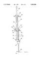
- FIG. 1is a front perspective view of an embodiment of the present invention.
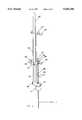
- FIGS. 2-4are front perspective views of the embodiment of FIG. 1 at different stages of use.
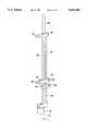
- FIG. 5is a rear perspective view of the embodiment of FIG. 1.
- FIG. 6is an exploded front view of the lower portion of the embodiment of FIG. 1.
- FIGS. 1-6describes one apparatus according to the present invention which is particularly useful in inserting a cannula into the brain, through which cannula an implant may be inserted. While this embodiment describes a microdrive which is particularly suited for cannula insertion into the brain, it should be understood that the basic structure, design and operation of the apparatus is the same for whatever surgical instrument is being inserted and whatever instrument holding member is being used.
- a microdrive 10 of the present inventioncomprises a base member 12 having an adapter base portion 14 and a base stop portion 16. As shown, the two portions of the base member are integral therewith. However, they may be separate members fixedly attached to each other.
- the base member 12has a channel which extends therethrough so that a surgical instrument which is attached to the instrument holder can pass therethrough in use. The channel is best shown in FIGS. 2-4.
- the base member as shown in FIG. 1is designed for use with the Radionics® BRW head frame assembly. For use with other head assemblies, other adapter bases (the shape and size of which are readily determinable from measurements of the mounting block of the particular stereotactic frame being used) or an adapter sleeve may be used.
- Attached to the base member 12is a guide member shown generally as 18.
- the guide member in this embodimentis composed of two elongated cylindrical rods 20 and 22 which are fixedly attached to the base member 12.
- Stop member 24 containing a screw clamp 25is slidably attached to guide member 18.
- the slidable attachmentis achieved by means of two channels which pass through the stop member through which the rods 20 and 22 pass.
- the stop memberis able to slide up and down along the longitudinal axis of the guide member.
- the stop member 24may be temporarily fixedly attached to the guide member 18 by tightening the screw 26 against rod 22.
- Fixedly attached to the stop member 24is a measuring member 28, which contains measuring indicia 30 thereon.
- Such measuring memberis generally in the form of a ruler with an appropriate scale and measuring indicia corresponding thereto.
- the scaleis a conventional metric scale. In use, as the stop member slides up and down the guide member 18, the measuring member follows.
- Instrument holding member 32is likewise slidably attached to the guide member 18. Like the stop member 24, the instrument holding member 32 has two channels through which the rods 20 and 22 pass. This arrangement permits movement of the instrument holding member along the longitudinal axis of the guide member 18, but prevents movement in any other direction. Again, like the stop member 24, the instrument holding member may be temporarily fixedly attached to the guide member 18 by tightening screw 34 against rod 22.
- the instrument holding member 32contains a notch 36 for holding a cannula which may be held in place by a screw 38. As shown, the measuring member 28 is disposed so that it may slide through a notch 40 in instrument holding member 32. This permits unrestricted movement of the stop member 24 relative to the instrument holding member 32.
- the channels in each of the stop member 24 and the instrument holding member 32preferably contain means to maintain sufficient pressure to hold the members 24 and 32 in place until intentionally changed.
- Suitable such meansinclude bushings 24a, 24b, 32a, and 32b, although other means (not shown) such as leaf springs, jack screws, or captured sliders may be used.
- the meansare bushings which are generally made from or at least coated with a low friction material such as Teflon® or Rulon® material.
- the bushings or other meansallow the stop member and the instrument holding member to ride smoothly along the rods 20 and 22, which are in contact with the bushings, in response to external pressure (surgeon's manipulations) while substantially holding the members 24 and 32 in place when no pressure is being applied. This keeps the members 24 and 32 from suddenly crashing down and causing the instrument to "free fall".
- this embodimentshows a second instrument holding member 42 which is fixedly attached to the distal end of the guide member 18.
- the second instrument holding member 42has a notch 44 which permits the measuring member 28 to slide therethrough.
- the second instrument holding memberalso has a notch 46 with a screw 48 for holding an instrument.
- a cannulawill be inserted into the first instrument holding member 32 with an obturator in place inside the cannula.
- the obturatorserves to part tissue, keep the cannula from scoring tissue, and keep the cannula substantially rigid during insertion.
- the obturatormay or may not be imageable.
- the second instrument holding member 42can then hold a pusher with an implant mounted on the end or another instrument (not shown in the drawings). After the obturator has been removed from the cannula, an implant or other instrument may be fed into the cannula and the top of the pusher may be locked into the second instrument holder. Alternatively, the implant or other instrument can simply be inserted into the cannula without use of the holding member 42.
- All of the elements of the microdriveshould be made of materials which are sterilizable by common methods, including both gas and autoclave means.
- the materialsare rigid and preferably light weight.
- the rods 20 and 22 which comprise the guide member 18can be made of such as graphite reinforced composite or a metal such as stainless steel.
- the base member 12, the stop member 24, and the instrument holding members 32 and 42can be made of aluminum, titanium, stainless steel, or high temperature resistant plastics.
- the instrument holding member 32is interchanged with other instrument holding members with slightly different means suitable for holding surgical instruments other than cannulas.
- surgical instrumentsinclude electrodes, biopsy instruments, etc.
- microdrive apparatus of the present inventioncan best be described with reference to FIGS. 2-4. While the discussion will be with reference to cannula insertion into a brain, it should be understood that the operation of the apparatus which holds another surgical instrument for insertion into other portions of the central nervous system is substantially the same.
- the target point and a 0 pointare established by any of a number of techniques, such as CT and MRI. Once a 0 point is established relative to the target point within the brain, the necessary adjustments are made with the stereotactic head assembly and the necessary hole or holes are drilled through the patients skull down to the dura. Although not shown, the microdrive is attached to a head assembly at this point in the surgical procedure and oriented in the appropriate direction to facilitate surgical instrument placement in the brain.
- the instrument holding member 32holds a cannula 50 having a stem 51 in place.
- an obturatorhaving a top portion 57 which extends to the tip of the cannula 56 with the obturator's tip 57 extending just beyond the tip of the cannula 56.
- the cannulagenerally includes a conventional luer style taper lock 55 to maintain the obturator in place.
- the stop member 24 and the instrument holding memberare then held together and adjusted on the guide member 18 to a position so that the obturator tip 57 is at the 0 point, e.g. the skin of the scalp of the patient.
- both membersare temporarily held in place by tightening screws 26 and 34 against the rod 26.
- the screw on the stop memberis loosened and it is moved downward or towards the base a predetermined distance equal to the pre-measured distance to the target from point 0. This distance is easily determined using the measuring member 28 and the scale printed thereon. In the embodiment shown in FIG. 4, this distance is identified as 5 mm, although the drawings are not to scale.
- the cannula with obturator thereinis inserted into the brain the premeasured distance (in this case 5 mm) to the target point. Screw 34 is then tightened preventing movement in any direction of the instrument holding member 32 or cannula 50. Now that the cannula tip is at the target point, the obturator may be removed and other surgical devices may be lowered through the cannula into the brain, such as an implant device, and held in place by means of the second instrument holding member 42 and screw 46.
- the general operation of the microdriveis the same excepting the need and use of the second instrument holding member 42 which is only needed when a second surgical instrument is used.
- An example of an alternative second instrumentis a single action biopsy forceps such as that designed for use with the Leksell Stereotactic Instrument.
- a patientwas fitted with a stereotactic head ring assembly and localizer ring (or image localization/marker device) suitable for guided cannula placement within the lateral ventricles using local anesthesia (local infiltration with generally 1% lidocaine).
- the Radioinics® BRW framewas used. (The Radionics® CRW, Leksell® and functionally similar devices are also appropriate.)
- a computed tomography (CT) scanhad been performed and was used to define one or more target sites and stereotactic coordinates for the implant(s).
- CTcomputed tomography
- implantation cannula trajectory and implant siteare chosen with the following considerations: (1) avoiding the frontal sinuses; (2) avoiding the choroid plexus; and (3) allowing straight, undistorted positioning capsule lengths 2.5, 3.75, or 5.0 cm).
- a target sitemust be selected that will allow a length of the internal end of the cannula, i.e. at least the length of the membrane portion of the desired capsule, to lie within an acceptable, CSF filled space within the ventricle.
- the zero reference point for determining cannula insertion depthwas the surface of the skin, as seen on the CT scan, and the target site was defined as the intended target of the internal tip (opening) of the inserting cannula.
- Two implant devicesmay be placed in one patient at a single procedure by placing one implant in each lateral ventricle. Future implantation sites may target the third ventricle, the aqueduct, and/or solid brain structures.
- the patientAfter establishing IV access and administering prophylactic antibiotics (currently, cefazolin sodium, 1 gram IV), the patient was positioned on the operating table in the semi-supine/seated position with the stereotactic head ring assembly secured to the table.
- the operative fieldwas sterilely prepared and draped exposing the intended implantation site(s) (generally located in the paramedian, frontal region) and allowing for sterile placement and removal of the stereotactic arc system/manipulator to the frame base.
- implantation kitspecific for ventricular insertion
- the stereotaxic microdrive(CytoTherapeutics, Inc. custom fabrication, mounted in the guide block of the transverse arch slide of the arc system for use) and directed into the burr hole.
- Blood from the woundwas excluded from the burr hole by applying the microdrive guide tube (CytoTherapeutics, Inc. custom fabrication) directly against the rim of the burr hole.
- the insertion cannula/obturator assemblywere advanced manually to the preset depth stop on the microdrive, leaving the tip of the cannula at the target site. The obturator was then carefully withdrawn from the insertion cannula, taking care not to deflect the cannula with the top of the obturator.
- CSFcerebrospinal fluid
- the encapsulated adrenal chromaffin cell graft(CytoTherapeutics, Inc. Cerecrib® R) was provided in a sterile, double envelope container, bathed in transport medium, and fully assembled including a tubular silicone tether.
- the capsulePrior to implantation through the insertion cannula and into the ventricle, the capsule was transferred to the insertion kit tray (CytoTherapeutics, Inc. implantation kit) where it was positioned in a location that allows the capsule to be maintained in transport medium while it is grossly examined for damage or major defects, and while the silicone tether was trimmed, adjusting its length to the pusher and removing the hemaclip that plugs its external stainless steel pusher (CytoTherapeutics, Inc. implantation kit, specific for insertion cannula and membrane capsule length) by inserting the small diameter wire portion of the pusher into the full length of the tether to stiffen the tether for passage through the cannula.
- the Cerecrib capsulewas handled completely by the silicone tether and the handle of the pusher as the membrane portion of the device was carefully introduced into the cannula.
- the capsulewas advanced until the tip of the cannula positioned in the subarachnoid space (but not extending beyond the tip of the cannula positioned in the subarachnoid space (but not extending beyond the tip of the cannula). This placement was achieved by premeasuring the cannula and the capsule-tether-pusher assembly, and it assures that the membrane portion of the capsule is protected by the cannula for the entire time that it is being advanced into position.
- the pusheris locked into position in the microdrive and used to hold the capsule in position in the ventricle (without advancing or withdrawing) while the cannula is completely withdrawn from over the capsule and pusher.
- the pusherwas then removed from the capsule by sliding its wire portion out of the silicone tether.
- the membrane capsulewas anchored at its external end by a length of silicone tether that runs (generally) through a portion of the frontal lobe before it exits through the dura and the skull, leaving generally 5-10 cm of free tether material that was available for securing the device.
- the free end of the tetherwas then anchored to the outer table of the skull adjacent to the burr hole using a standard, maxillo-facial miniplate and screws and completely covered with a 2 or 3 layer closure.
- the patientwas then transferred to the neurosurgical recovery area and followed for 12 hours postoperatively for potential hemorrhage complications with no special restrictions. Antibiotic prophylaxis was also continued for 24 hours following the implantation procedure.
Landscapes
- Health & Medical Sciences (AREA)
- Surgery (AREA)
- Life Sciences & Earth Sciences (AREA)
- Molecular Biology (AREA)
- General Health & Medical Sciences (AREA)
- Oral & Maxillofacial Surgery (AREA)
- Engineering & Computer Science (AREA)
- Biomedical Technology (AREA)
- Heart & Thoracic Surgery (AREA)
- Medical Informatics (AREA)
- Nuclear Medicine, Radiotherapy & Molecular Imaging (AREA)
- Animal Behavior & Ethology (AREA)
- Pathology (AREA)
- Public Health (AREA)
- Veterinary Medicine (AREA)
- Magnetic Resonance Imaging Apparatus (AREA)
- Surgical Instruments (AREA)
- Prostheses (AREA)
- Materials For Medical Uses (AREA)
- Endoscopes (AREA)
Abstract
Description
Claims (12)
Priority Applications (12)
| Application Number | Priority Date | Filing Date | Title |
|---|---|---|---|
| US08/265,242US5643286A (en) | 1994-06-24 | 1994-06-24 | Microdrive for use in stereotactic surgery |
| ES95923106TES2168368T3 (en) | 1994-06-24 | 1995-06-21 | MICROACTUATOR TO USE IN STEREOTACTIC SURGERY. |
| EP95923106AEP0862388B1 (en) | 1994-06-24 | 1995-06-21 | Microdrive for use in stereotactic surgery |
| JP8503319AJP2955366B2 (en) | 1994-06-24 | 1995-06-21 | Microdrive used in stereotaxic surgery |
| DE69524124TDE69524124T2 (en) | 1994-06-24 | 1995-06-21 | INSTRUMENT HOLDER FOR USE IN STEREOTACTIC SURGERY |
| MX9606721AMX9606721A (en) | 1994-06-24 | 1995-06-21 | Microdrive for use in stereotactic surgery. |
| DK95923106TDK0862388T3 (en) | 1994-06-24 | 1995-06-21 | Microdrives for stereotactic surgery |
| AU27776/95AAU703470B2 (en) | 1994-06-24 | 1995-06-21 | Microdrive for use in stereotactic surgery |
| CA002193361ACA2193361A1 (en) | 1994-06-24 | 1995-06-21 | Microdrive for use in stereotactic surgery |
| PCT/US1995/007929WO1996000044A1 (en) | 1994-06-24 | 1995-06-21 | Microdrive for use in stereotactic surgery |
| AT95923106TATE209020T1 (en) | 1994-06-24 | 1995-06-21 | INSTRUMENT HOLDER FOR USE IN STEREOTACTIC SURGERY |
| US08/814,594US5871487A (en) | 1994-06-24 | 1997-03-10 | Microdrive for use in stereotactic surgery |
Applications Claiming Priority (1)
| Application Number | Priority Date | Filing Date | Title |
|---|---|---|---|
| US08/265,242US5643286A (en) | 1994-06-24 | 1994-06-24 | Microdrive for use in stereotactic surgery |
Related Child Applications (1)
| Application Number | Title | Priority Date | Filing Date |
|---|---|---|---|
| US08/814,594ContinuationUS5871487A (en) | 1994-06-24 | 1997-03-10 | Microdrive for use in stereotactic surgery |
Publications (1)
| Publication Number | Publication Date |
|---|---|
| US5643286Atrue US5643286A (en) | 1997-07-01 |
Family
ID=23009623
Family Applications (2)
| Application Number | Title | Priority Date | Filing Date |
|---|---|---|---|
| US08/265,242Expired - LifetimeUS5643286A (en) | 1994-06-24 | 1994-06-24 | Microdrive for use in stereotactic surgery |
| US08/814,594Expired - LifetimeUS5871487A (en) | 1994-06-24 | 1997-03-10 | Microdrive for use in stereotactic surgery |
Family Applications After (1)
| Application Number | Title | Priority Date | Filing Date |
|---|---|---|---|
| US08/814,594Expired - LifetimeUS5871487A (en) | 1994-06-24 | 1997-03-10 | Microdrive for use in stereotactic surgery |
Country Status (11)
| Country | Link |
|---|---|
| US (2) | US5643286A (en) |
| EP (1) | EP0862388B1 (en) |
| JP (1) | JP2955366B2 (en) |
| AT (1) | ATE209020T1 (en) |
| AU (1) | AU703470B2 (en) |
| CA (1) | CA2193361A1 (en) |
| DE (1) | DE69524124T2 (en) |
| DK (1) | DK0862388T3 (en) |
| ES (1) | ES2168368T3 (en) |
| MX (1) | MX9606721A (en) |
| WO (1) | WO1996000044A1 (en) |
Cited By (33)
| Publication number | Priority date | Publication date | Assignee | Title |
|---|---|---|---|---|
| US5817106A (en)* | 1995-09-19 | 1998-10-06 | Real; Douglas D. | Stereotactic guide apparatus for use with neurosurgical headframe |
| WO1999035991A1 (en)* | 1998-01-20 | 1999-07-22 | Elekta Ab | Lock device for surgical instruments |
| US5993463A (en)* | 1997-05-15 | 1999-11-30 | Regents Of The University Of Minnesota | Remote actuation of trajectory guide |
| US6195577B1 (en) | 1998-10-08 | 2001-02-27 | Regents Of The University Of Minnesota | Method and apparatus for positioning a device in a body |
| US20020049451A1 (en)* | 2000-08-17 | 2002-04-25 | Kari Parmer | Trajectory guide with instrument immobilizer |
| US6413263B1 (en) | 2000-04-24 | 2002-07-02 | Axon Instruments, Inc. | Stereotactic probe holder and method of use |
| US6416520B1 (en) | 1999-04-23 | 2002-07-09 | Sherwood Services Ag | Microdrive for probes |
| US6491699B1 (en) | 1999-04-20 | 2002-12-10 | Surgical Navigation Technologies, Inc. | Instrument guidance method and system for image guided surgery |
| US6665554B1 (en) | 1998-11-18 | 2003-12-16 | Steve T. Charles | Medical manipulator for use with an imaging device |
| US6676669B2 (en) | 2001-01-16 | 2004-01-13 | Microdexterity Systems, Inc. | Surgical manipulator |
| US20040024385A1 (en)* | 1999-11-12 | 2004-02-05 | Microdexterity Systems, Inc. | Manipulator |
| US6723106B1 (en) | 1998-11-23 | 2004-04-20 | Microdexterity Systems, Inc. | Surgical manipulator |
| US6752812B1 (en) | 1997-05-15 | 2004-06-22 | Regent Of The University Of Minnesota | Remote actuation of trajectory guide |
| US20040220567A1 (en)* | 2003-02-12 | 2004-11-04 | Sdgi Holdings, Inc. | Instruments and methods for aligning implants for insertion |
| US20050125007A1 (en)* | 2002-03-12 | 2005-06-09 | Gill Steven S. | Stereoguide for clamping neurosurgical instruments |
| US7204840B2 (en) | 2000-04-07 | 2007-04-17 | Image-Guided Neurologics, Inc. | Deep organ access device and method |
| US20070250078A1 (en)* | 2001-01-16 | 2007-10-25 | Microdexterity Systems, Inc. | Surgical manipulator |
| US7497863B2 (en) | 2004-12-04 | 2009-03-03 | Medtronic, Inc. | Instrument guiding stage apparatus and method for using same |
| WO2009032838A1 (en)* | 2007-09-08 | 2009-03-12 | Merck & Co., Inc. | Microdrive and modular microdrive assembly for positioning instruments in animal bodies |
| US7559935B2 (en) | 2003-02-20 | 2009-07-14 | Medtronic, Inc. | Target depth locators for trajectory guide for introducing an instrument |
| US20090192487A1 (en)* | 2006-07-27 | 2009-07-30 | University Of Virginia Patent Foundation | System and Method for Intracranial Implantation of Therapeutic or Diagnostic Agents |
| US7636596B2 (en) | 2002-12-20 | 2009-12-22 | Medtronic, Inc. | Organ access device and method |
| US7658879B2 (en) | 2003-02-20 | 2010-02-09 | Medtronic, Inc. | Trajectory guide with angled or patterned guide lumens or height adjustment |
| US7704260B2 (en) | 2002-09-17 | 2010-04-27 | Medtronic, Inc. | Low profile instrument immobilizer |
| US7744606B2 (en) | 2004-12-04 | 2010-06-29 | Medtronic, Inc. | Multi-lumen instrument guide |
| US20100275718A1 (en)* | 2009-04-29 | 2010-11-04 | Microdexterity Systems, Inc. | Manipulator |
| US20110088500A1 (en)* | 2007-02-23 | 2011-04-21 | Microdexterity Systems, Inc. | Manipulator |
| US20120259219A1 (en)* | 2011-04-05 | 2012-10-11 | Houston Medical Robotics, Inc. | Systems and methods for accessing the lumen of a vessel |
| US20150265312A1 (en)* | 2014-03-21 | 2015-09-24 | Nabil J. Abu Nassar | Selectively implementable multi-probe microdrive |
| US10086193B2 (en) | 2004-02-13 | 2018-10-02 | Medtronic, Inc. | Apparatus for securing a therapy delivery device within a burr hole and method for making same |
| US11298041B2 (en) | 2016-08-30 | 2022-04-12 | The Regents Of The University Of California | Methods for biomedical targeting and delivery and devices and systems for practicing the same |
| US11497576B2 (en) | 2017-07-17 | 2022-11-15 | Voyager Therapeutics, Inc. | Trajectory array guide system |
| US12108965B2 (en) | 2019-07-02 | 2024-10-08 | Musc Foundation For Research Development | Minimally invasive subdural evacuating system |
Families Citing this family (131)
| Publication number | Priority date | Publication date | Assignee | Title |
|---|---|---|---|---|
| FR2652928B1 (en) | 1989-10-05 | 1994-07-29 | Diadix Sa | INTERACTIVE LOCAL INTERVENTION SYSTEM WITHIN A AREA OF A NON-HOMOGENEOUS STRUCTURE. |
| AU675077B2 (en)* | 1992-08-14 | 1997-01-23 | British Telecommunications Public Limited Company | Position location system |
| US5814038A (en)* | 1995-06-07 | 1998-09-29 | Sri International | Surgical manipulator for a telerobotic system |
| US5592939A (en) | 1995-06-14 | 1997-01-14 | Martinelli; Michael A. | Method and system for navigating a catheter probe |
| US6226418B1 (en) | 1997-11-07 | 2001-05-01 | Washington University | Rapid convolution based large deformation image matching via landmark and volume imagery |
| US6611630B1 (en) | 1996-07-10 | 2003-08-26 | Washington University | Method and apparatus for automatic shape characterization |
| US6408107B1 (en) | 1996-07-10 | 2002-06-18 | Michael I. Miller | Rapid convolution based large deformation image matching via landmark and volume imagery |
| US6009212A (en) | 1996-07-10 | 1999-12-28 | Washington University | Method and apparatus for image registration |
| US6708184B2 (en) | 1997-04-11 | 2004-03-16 | Medtronic/Surgical Navigation Technologies | Method and apparatus for producing and accessing composite data using a device having a distributed communication controller interface |
| US5970499A (en) | 1997-04-11 | 1999-10-19 | Smith; Kurt R. | Method and apparatus for producing and accessing composite data |
| US6226548B1 (en)* | 1997-09-24 | 2001-05-01 | Surgical Navigation Technologies, Inc. | Percutaneous registration apparatus and method for use in computer-assisted surgical navigation |
| US6021343A (en) | 1997-11-20 | 2000-02-01 | Surgical Navigation Technologies | Image guided awl/tap/screwdriver |
| US6348058B1 (en) | 1997-12-12 | 2002-02-19 | Surgical Navigation Technologies, Inc. | Image guided spinal surgery guide, system, and method for use thereof |
| US6298262B1 (en) | 1998-04-21 | 2001-10-02 | Neutar, Llc | Instrument guidance for stereotactic surgery |
| US6529765B1 (en) | 1998-04-21 | 2003-03-04 | Neutar L.L.C. | Instrumented and actuated guidance fixture for sterotactic surgery |
| US6546277B1 (en)* | 1998-04-21 | 2003-04-08 | Neutar L.L.C. | Instrument guidance system for spinal and other surgery |
| US6118845A (en) | 1998-06-29 | 2000-09-12 | Surgical Navigation Technologies, Inc. | System and methods for the reduction and elimination of image artifacts in the calibration of X-ray imagers |
| US6916000B2 (en)* | 1998-07-02 | 2005-07-12 | Jeffrey N. Weiss | Apparatus and method for cannulating retinal blood vessels |
| US6351662B1 (en) | 1998-08-12 | 2002-02-26 | Neutar L.L.C. | Movable arm locator for stereotactic surgery |
| US6282437B1 (en) | 1998-08-12 | 2001-08-28 | Neutar, Llc | Body-mounted sensing system for stereotactic surgery |
| US6477400B1 (en)* | 1998-08-20 | 2002-11-05 | Sofamor Danek Holdings, Inc. | Fluoroscopic image guided orthopaedic surgery system with intraoperative registration |
| US6482182B1 (en) | 1998-09-03 | 2002-11-19 | Surgical Navigation Technologies, Inc. | Anchoring system for a brain lead |
| WO2000021442A1 (en) | 1998-10-09 | 2000-04-20 | Surgical Navigation Technologies, Inc. | Image guided vertebral distractor |
| US6470207B1 (en) | 1999-03-23 | 2002-10-22 | Surgical Navigation Technologies, Inc. | Navigational guidance via computer-assisted fluoroscopic imaging |
| US6689142B1 (en) | 1999-04-26 | 2004-02-10 | Scimed Life Systems, Inc. | Apparatus and methods for guiding a needle |
| DE69930154T2 (en)* | 1999-04-26 | 2006-11-16 | Boston Scientific Ltd., Bush Hill | DEVICE FOR LEADING A NEEDLE |
| US7553290B1 (en) | 1999-06-04 | 2009-06-30 | Medtronic Ps Medical, Inc. | Subdural evacuating port aspiration system |
| US6923799B1 (en)* | 1999-06-04 | 2005-08-02 | Wilson T. Asfora | Subdural evacuating port system |
| SE514693C2 (en)* | 1999-09-23 | 2001-04-02 | Elekta Ab | Stereotactic apparatus |
| US6221087B1 (en)* | 1999-10-01 | 2001-04-24 | Scimed Life Systems, Inc. | Ablation assembly with safety stop |
| US11331150B2 (en) | 1999-10-28 | 2022-05-17 | Medtronic Navigation, Inc. | Method and apparatus for surgical navigation |
| US6499488B1 (en) | 1999-10-28 | 2002-12-31 | Winchester Development Associates | Surgical sensor |
| US7366562B2 (en)* | 2003-10-17 | 2008-04-29 | Medtronic Navigation, Inc. | Method and apparatus for surgical navigation |
| US8239001B2 (en)* | 2003-10-17 | 2012-08-07 | Medtronic Navigation, Inc. | Method and apparatus for surgical navigation |
| US6379302B1 (en) | 1999-10-28 | 2002-04-30 | Surgical Navigation Technologies Inc. | Navigation information overlay onto ultrasound imagery |
| US8644907B2 (en)* | 1999-10-28 | 2014-02-04 | Medtronic Navigaton, Inc. | Method and apparatus for surgical navigation |
| US6493573B1 (en)* | 1999-10-28 | 2002-12-10 | Winchester Development Associates | Method and system for navigating a catheter probe in the presence of field-influencing objects |
| US6474341B1 (en) | 1999-10-28 | 2002-11-05 | Surgical Navigation Technologies, Inc. | Surgical communication and power system |
| US6381485B1 (en)* | 1999-10-28 | 2002-04-30 | Surgical Navigation Technologies, Inc. | Registration of human anatomy integrated for electromagnetic localization |
| USD442281S1 (en) | 1999-12-13 | 2001-05-15 | Elekta Ab | Stereotactic apparatus |
| US6725080B2 (en)* | 2000-03-01 | 2004-04-20 | Surgical Navigation Technologies, Inc. | Multiple cannula image guided tool for image guided procedures |
| US6535756B1 (en) | 2000-04-07 | 2003-03-18 | Surgical Navigation Technologies, Inc. | Trajectory storage apparatus and method for surgical navigation system |
| US7085400B1 (en)* | 2000-06-14 | 2006-08-01 | Surgical Navigation Technologies, Inc. | System and method for image based sensor calibration |
| US6636757B1 (en)* | 2001-06-04 | 2003-10-21 | Surgical Navigation Technologies, Inc. | Method and apparatus for electromagnetic navigation of a surgical probe near a metal object |
| GB0126850D0 (en)* | 2001-11-08 | 2002-01-02 | Tayside University Hospitals N | Localisation system |
| US7169155B2 (en) | 2001-12-14 | 2007-01-30 | Scimed Life Systems, Inc. | Methods and apparatus for guiding a needle |
| US6947786B2 (en)* | 2002-02-28 | 2005-09-20 | Surgical Navigation Technologies, Inc. | Method and apparatus for perspective inversion |
| US7011658B2 (en)* | 2002-03-04 | 2006-03-14 | Sdgi Holdings, Inc. | Devices and methods for spinal compression and distraction |
| US6990368B2 (en)* | 2002-04-04 | 2006-01-24 | Surgical Navigation Technologies, Inc. | Method and apparatus for virtual digital subtraction angiography |
| US7998062B2 (en) | 2004-03-29 | 2011-08-16 | Superdimension, Ltd. | Endoscope structures and techniques for navigating to a target in branched structure |
| US6892090B2 (en)* | 2002-08-19 | 2005-05-10 | Surgical Navigation Technologies, Inc. | Method and apparatus for virtual endoscopy |
| US7824417B2 (en)* | 2002-09-05 | 2010-11-02 | Aprio Medical Ab | Guide for a medical device |
| US7697972B2 (en)* | 2002-11-19 | 2010-04-13 | Medtronic Navigation, Inc. | Navigation system for cardiac therapies |
| US7599730B2 (en)* | 2002-11-19 | 2009-10-06 | Medtronic Navigation, Inc. | Navigation system for cardiac therapies |
| US7542791B2 (en) | 2003-01-30 | 2009-06-02 | Medtronic Navigation, Inc. | Method and apparatus for preplanning a surgical procedure |
| US7660623B2 (en) | 2003-01-30 | 2010-02-09 | Medtronic Navigation, Inc. | Six degree of freedom alignment display for medical procedures |
| US7628762B2 (en)* | 2003-03-19 | 2009-12-08 | Suros Surgical Systems, Inc. | Adapter assembly for stereotactic biopsy |
| US7570791B2 (en)* | 2003-04-25 | 2009-08-04 | Medtronic Navigation, Inc. | Method and apparatus for performing 2D to 3D registration |
| US7313430B2 (en) | 2003-08-28 | 2007-12-25 | Medtronic Navigation, Inc. | Method and apparatus for performing stereotactic surgery |
| EP2113189B1 (en) | 2003-09-15 | 2013-09-04 | Covidien LP | System of accessories for use with bronchoscopes |
| EP2316328B1 (en) | 2003-09-15 | 2012-05-09 | Super Dimension Ltd. | Wrap-around holding device for use with bronchoscopes |
| US7835778B2 (en) | 2003-10-16 | 2010-11-16 | Medtronic Navigation, Inc. | Method and apparatus for surgical navigation of a multiple piece construct for implantation |
| US7840253B2 (en)* | 2003-10-17 | 2010-11-23 | Medtronic Navigation, Inc. | Method and apparatus for surgical navigation |
| US8764725B2 (en)* | 2004-02-09 | 2014-07-01 | Covidien Lp | Directional anchoring mechanism, method and applications thereof |
| US7567834B2 (en)* | 2004-05-03 | 2009-07-28 | Medtronic Navigation, Inc. | Method and apparatus for implantation between two vertebral bodies |
| US6938897B1 (en)* | 2004-07-02 | 2005-09-06 | Walter C. Napiorkowski | Universal role playing game elevation indicator system |
| US7636595B2 (en)* | 2004-10-28 | 2009-12-22 | Medtronic Navigation, Inc. | Method and apparatus for calibrating non-linear instruments |
| EP1827243B1 (en)* | 2004-11-05 | 2010-01-20 | THE GOVERNMENT OF THE UNITED STATES OF AMERICA, as represented by THE SECRETARY, DEPARTMENT OF HEALTH AND HUMAN SERVICES | Access system |
| EP1869162A1 (en)* | 2005-04-01 | 2007-12-26 | NsGene A/S | A human immortalised neural precursor cell line |
| ES2653844T3 (en)* | 2005-05-17 | 2018-02-09 | Gloriana Therapeutics Sarl | An implantable therapy system to treat a living being with an active factor |
| US7835784B2 (en) | 2005-09-21 | 2010-11-16 | Medtronic Navigation, Inc. | Method and apparatus for positioning a reference frame |
| US9168102B2 (en)* | 2006-01-18 | 2015-10-27 | Medtronic Navigation, Inc. | Method and apparatus for providing a container to a sterile environment |
| DE102006004993A1 (en)* | 2006-02-01 | 2007-08-09 | Innomedic Gmbh | Method and device for performing minimally invasive interventions |
| US8112292B2 (en)* | 2006-04-21 | 2012-02-07 | Medtronic Navigation, Inc. | Method and apparatus for optimizing a therapy |
| US8660635B2 (en) | 2006-09-29 | 2014-02-25 | Medtronic, Inc. | Method and apparatus for optimizing a computer assisted surgical procedure |
| US8905920B2 (en)* | 2007-09-27 | 2014-12-09 | Covidien Lp | Bronchoscope adapter and method |
| WO2009122273A2 (en) | 2008-04-03 | 2009-10-08 | Superdimension, Ltd. | Magnetic interference detection system and method |
| US8092495B2 (en)* | 2008-04-04 | 2012-01-10 | The Cleveland Clinic Foundation | Spinal platform and method for delivering a therapeutic agent to a spinal cord target |
| US9345875B2 (en)* | 2008-04-17 | 2016-05-24 | Medtronic, Inc. | Method and apparatus for cannula fixation for an array insertion tube set |
| WO2009143177A2 (en)* | 2008-05-19 | 2009-11-26 | Nevro Corporation | Implantable neural stimulation electrode assemblies and methods for stimulating spinal neural sites |
| EP2297673B1 (en) | 2008-06-03 | 2020-04-22 | Covidien LP | Feature-based registration method |
| US8218847B2 (en) | 2008-06-06 | 2012-07-10 | Superdimension, Ltd. | Hybrid registration method |
| EP2337517B1 (en) | 2008-07-03 | 2013-01-09 | The Cleveland Clinic Foundation | Floating spinal cannula |
| US8932207B2 (en) | 2008-07-10 | 2015-01-13 | Covidien Lp | Integrated multi-functional endoscopic tool |
| US8165658B2 (en) | 2008-09-26 | 2012-04-24 | Medtronic, Inc. | Method and apparatus for positioning a guide relative to a base |
| US9403020B2 (en) | 2008-11-04 | 2016-08-02 | Nevro Corporation | Modeling positions of implanted devices in a patient |
| US8175681B2 (en)* | 2008-12-16 | 2012-05-08 | Medtronic Navigation Inc. | Combination of electromagnetic and electropotential localization |
| US8611984B2 (en)* | 2009-04-08 | 2013-12-17 | Covidien Lp | Locatable catheter |
| US8494614B2 (en)* | 2009-08-31 | 2013-07-23 | Regents Of The University Of Minnesota | Combination localization system |
| US8494613B2 (en) | 2009-08-31 | 2013-07-23 | Medtronic, Inc. | Combination localization system |
| US10582834B2 (en) | 2010-06-15 | 2020-03-10 | Covidien Lp | Locatable expandable working channel and method |
| US8805519B2 (en) | 2010-09-30 | 2014-08-12 | Nevro Corporation | Systems and methods for detecting intrathecal penetration |
| US8965482B2 (en)* | 2010-09-30 | 2015-02-24 | Nevro Corporation | Systems and methods for positioning implanted devices in a patient |
| JP6021484B2 (en)* | 2011-08-04 | 2016-11-09 | オリンパス株式会社 | Medical manipulator |
| JP5936914B2 (en) | 2011-08-04 | 2016-06-22 | オリンパス株式会社 | Operation input device and manipulator system including the same |
| JP6005950B2 (en) | 2011-08-04 | 2016-10-12 | オリンパス株式会社 | Surgery support apparatus and control method thereof |
| JP5953058B2 (en) | 2011-08-04 | 2016-07-13 | オリンパス株式会社 | Surgery support device and method for attaching and detaching the same |
| JP5931497B2 (en) | 2011-08-04 | 2016-06-08 | オリンパス株式会社 | Surgery support apparatus and assembly method thereof |
| WO2013018908A1 (en) | 2011-08-04 | 2013-02-07 | オリンパス株式会社 | Manipulator for medical use and surgery support device |
| JP6009840B2 (en) | 2011-08-04 | 2016-10-19 | オリンパス株式会社 | Medical equipment |
| KR20130063968A (en)* | 2011-12-07 | 2013-06-17 | 한림대학교 산학협력단 | Micro-drive device for sampling the electical signal of the nerve |
| AU2013211937B2 (en) | 2012-01-25 | 2016-07-28 | Nevro Corporation | Lead anchors and associated systems and methods |
| US8676331B2 (en) | 2012-04-02 | 2014-03-18 | Nevro Corporation | Devices for controlling spinal cord modulation for inhibiting pain, and associated systems and methods, including controllers for automated parameter selection |
| WO2014047540A1 (en)* | 2012-09-24 | 2014-03-27 | The Regents Of The University Of California | Spinal cord pulsation-cancelation injection system |
| US9265935B2 (en) | 2013-06-28 | 2016-02-23 | Nevro Corporation | Neurological stimulation lead anchors and associated systems and methods |
| WO2015179177A1 (en) | 2014-05-20 | 2015-11-26 | Nevro Corporation | Implanted pulse generators with reduced power consumption via signal strength/duration characteristics, and associated systems and methods |
| US10952593B2 (en) | 2014-06-10 | 2021-03-23 | Covidien Lp | Bronchoscope adapter |
| US10426555B2 (en) | 2015-06-03 | 2019-10-01 | Covidien Lp | Medical instrument with sensor for use in a system and method for electromagnetic navigation |
| US9962134B2 (en) | 2015-10-28 | 2018-05-08 | Medtronic Navigation, Inc. | Apparatus and method for maintaining image quality while minimizing X-ray dosage of a patient |
| US10300277B1 (en) | 2015-12-14 | 2019-05-28 | Nevro Corp. | Variable amplitude signals for neurological therapy, and associated systems and methods |
| CN108884022B (en) | 2016-03-28 | 2022-01-28 | 加利福尼亚大学董事会 | Methods and compositions for treating neuronal hyperexcitability |
| US10478254B2 (en) | 2016-05-16 | 2019-11-19 | Covidien Lp | System and method to access lung tissue |
| US10418705B2 (en) | 2016-10-28 | 2019-09-17 | Covidien Lp | Electromagnetic navigation antenna assembly and electromagnetic navigation system including the same |
| US10751126B2 (en) | 2016-10-28 | 2020-08-25 | Covidien Lp | System and method for generating a map for electromagnetic navigation |
| US10446931B2 (en) | 2016-10-28 | 2019-10-15 | Covidien Lp | Electromagnetic navigation antenna assembly and electromagnetic navigation system including the same |
| US10722311B2 (en) | 2016-10-28 | 2020-07-28 | Covidien Lp | System and method for identifying a location and/or an orientation of an electromagnetic sensor based on a map |
| US10615500B2 (en) | 2016-10-28 | 2020-04-07 | Covidien Lp | System and method for designing electromagnetic navigation antenna assemblies |
| US10638952B2 (en) | 2016-10-28 | 2020-05-05 | Covidien Lp | Methods, systems, and computer-readable media for calibrating an electromagnetic navigation system |
| US10792106B2 (en) | 2016-10-28 | 2020-10-06 | Covidien Lp | System for calibrating an electromagnetic navigation system |
| US10517505B2 (en) | 2016-10-28 | 2019-12-31 | Covidien Lp | Systems, methods, and computer-readable media for optimizing an electromagnetic navigation system |
| US10980999B2 (en) | 2017-03-09 | 2021-04-20 | Nevro Corp. | Paddle leads and delivery tools, and associated systems and methods |
| CA3074587A1 (en) | 2017-09-08 | 2019-03-14 | The Regents Of The University Of California | Method and composition for treating neuropathic pain |
| US11219489B2 (en) | 2017-10-31 | 2022-01-11 | Covidien Lp | Devices and systems for providing sensors in parallel with medical tools |
| WO2019152553A1 (en) | 2018-01-30 | 2019-08-08 | Jon Parker | Efficient use of an implantable pulse generator battery, and associated systems and methods |
| WO2019191423A1 (en) | 2018-03-29 | 2019-10-03 | Nevro Corp. | Leads having sidewall openings, and associated systems and methods |
| US11058875B1 (en) | 2018-09-19 | 2021-07-13 | Nevro Corp. | Motor function in spinal cord injury patients via electrical stimulation, and associated systems and methods |
| JP7373226B2 (en)* | 2019-01-10 | 2023-11-02 | ザ リージェンツ オブ ザ ユニバーシティ オブ カリフォルニア | Subpial delivery system and method of use |
| US11590352B2 (en) | 2019-01-29 | 2023-02-28 | Nevro Corp. | Ramped therapeutic signals for modulating inhibitory interneurons, and associated systems and methods |
| US12089902B2 (en) | 2019-07-30 | 2024-09-17 | Coviden Lp | Cone beam and 3D fluoroscope lung navigation |
| USD963164S1 (en) | 2020-01-09 | 2022-09-06 | The Regents Of The University Of California | Surgical needle |
| US11407346B1 (en) | 2022-02-01 | 2022-08-09 | Brandon Mondfrans | Upper body support system |
Citations (15)
| Publication number | Priority date | Publication date | Assignee | Title |
|---|---|---|---|---|
| DE869842C (en)* | 1951-12-14 | 1953-03-09 | Werner Dr Boehlke | Facility for treating localized areas of the brain |
| US3223087A (en)* | 1960-06-18 | 1965-12-14 | Chirana Praha Np | Stereotaxic device |
| US3817249A (en)* | 1972-04-07 | 1974-06-18 | Neuro Probe Inc | Stereotaxic instrument |
| SU1055503A1 (en)* | 1981-11-19 | 1983-11-23 | Омский Государственный Ордена Трудового Красного Знамени Медицинский Институт Им.М.И.Калинина | Stereotaxic apparatus |
| FR2584601A1 (en)* | 1985-07-09 | 1987-01-16 | Poirier Alain | Device for punctures and biopsies which are guided by tomo-densitometric examination |
| US4653509A (en)* | 1985-07-03 | 1987-03-31 | The United States Of America As Represented By The Secretary Of The Air Force | Guided trephine samples for skeletal bone studies |
| US4722336A (en)* | 1985-01-25 | 1988-02-02 | Michael Kim | Placement guide |
| US4750487A (en)* | 1986-11-24 | 1988-06-14 | Zanetti Paul H | Stereotactic frame |
| US4875478A (en)* | 1987-04-10 | 1989-10-24 | Chen Harry H | Portable compression grid & needle holder |
| US4940061A (en)* | 1989-11-27 | 1990-07-10 | Ingress Technologies, Inc. | Biopsy instrument |
| US5056523A (en)* | 1989-11-22 | 1991-10-15 | Board Of Regents, The University Of Texas System | Precision breast lesion localizer |
| US5080662A (en)* | 1989-11-27 | 1992-01-14 | Paul Kamaljit S | Spinal stereotaxic device and method |
| US5154723A (en)* | 1987-12-02 | 1992-10-13 | Olympus Optical Co., Ltd. | Cerebral surgery apparatus |
| US5183465A (en)* | 1990-12-28 | 1993-02-02 | Dimitrios Xanthakos | Apparatus for supporting and moving needles and trocars for penetrating the abdomen |
| US5308352A (en)* | 1989-11-17 | 1994-05-03 | Koutrouvelis Panos G | Stereotactic device |
- 1994
- 1994-06-24USUS08/265,242patent/US5643286A/ennot_activeExpired - Lifetime
- 1995
- 1995-06-21ESES95923106Tpatent/ES2168368T3/ennot_activeExpired - Lifetime
- 1995-06-21DEDE69524124Tpatent/DE69524124T2/ennot_activeExpired - Fee Related
- 1995-06-21ATAT95923106Tpatent/ATE209020T1/ennot_activeIP Right Cessation
- 1995-06-21CACA002193361Apatent/CA2193361A1/ennot_activeAbandoned
- 1995-06-21WOPCT/US1995/007929patent/WO1996000044A1/enactiveIP Right Grant
- 1995-06-21JPJP8503319Apatent/JP2955366B2/ennot_activeExpired - Fee Related
- 1995-06-21AUAU27776/95Apatent/AU703470B2/ennot_activeCeased
- 1995-06-21EPEP95923106Apatent/EP0862388B1/ennot_activeExpired - Lifetime
- 1995-06-21MXMX9606721Apatent/MX9606721A/ennot_activeIP Right Cessation
- 1995-06-21DKDK95923106Tpatent/DK0862388T3/enactive
- 1997
- 1997-03-10USUS08/814,594patent/US5871487A/ennot_activeExpired - Lifetime
Patent Citations (15)
| Publication number | Priority date | Publication date | Assignee | Title |
|---|---|---|---|---|
| DE869842C (en)* | 1951-12-14 | 1953-03-09 | Werner Dr Boehlke | Facility for treating localized areas of the brain |
| US3223087A (en)* | 1960-06-18 | 1965-12-14 | Chirana Praha Np | Stereotaxic device |
| US3817249A (en)* | 1972-04-07 | 1974-06-18 | Neuro Probe Inc | Stereotaxic instrument |
| SU1055503A1 (en)* | 1981-11-19 | 1983-11-23 | Омский Государственный Ордена Трудового Красного Знамени Медицинский Институт Им.М.И.Калинина | Stereotaxic apparatus |
| US4722336A (en)* | 1985-01-25 | 1988-02-02 | Michael Kim | Placement guide |
| US4653509A (en)* | 1985-07-03 | 1987-03-31 | The United States Of America As Represented By The Secretary Of The Air Force | Guided trephine samples for skeletal bone studies |
| FR2584601A1 (en)* | 1985-07-09 | 1987-01-16 | Poirier Alain | Device for punctures and biopsies which are guided by tomo-densitometric examination |
| US4750487A (en)* | 1986-11-24 | 1988-06-14 | Zanetti Paul H | Stereotactic frame |
| US4875478A (en)* | 1987-04-10 | 1989-10-24 | Chen Harry H | Portable compression grid & needle holder |
| US5154723A (en)* | 1987-12-02 | 1992-10-13 | Olympus Optical Co., Ltd. | Cerebral surgery apparatus |
| US5308352A (en)* | 1989-11-17 | 1994-05-03 | Koutrouvelis Panos G | Stereotactic device |
| US5056523A (en)* | 1989-11-22 | 1991-10-15 | Board Of Regents, The University Of Texas System | Precision breast lesion localizer |
| US4940061A (en)* | 1989-11-27 | 1990-07-10 | Ingress Technologies, Inc. | Biopsy instrument |
| US5080662A (en)* | 1989-11-27 | 1992-01-14 | Paul Kamaljit S | Spinal stereotaxic device and method |
| US5183465A (en)* | 1990-12-28 | 1993-02-02 | Dimitrios Xanthakos | Apparatus for supporting and moving needles and trocars for penetrating the abdomen |
Non-Patent Citations (2)
| Title |
|---|
| Bland et al., "A Direct-Drive, Non-Rotating Version of Ranck's Microdrive", Physiology and Behavior, vol. 24, May 16, 1979, pp. 395-397. |
| Bland et al., A Direct Drive, Non Rotating Version of Ranck s Microdrive , Physiology and Behavior, vol. 24, May 16, 1979, pp. 395 397.* |
Cited By (78)
| Publication number | Priority date | Publication date | Assignee | Title |
|---|---|---|---|---|
| US5817106A (en)* | 1995-09-19 | 1998-10-06 | Real; Douglas D. | Stereotactic guide apparatus for use with neurosurgical headframe |
| US5993463A (en)* | 1997-05-15 | 1999-11-30 | Regents Of The University Of Minnesota | Remote actuation of trajectory guide |
| US6206890B1 (en) | 1997-05-15 | 2001-03-27 | Regents Of The University Of Minnesota | Remote actuation of trajectory guide |
| US6267770B1 (en) | 1997-05-15 | 2001-07-31 | Regents Of The University Of Minnesota | Remote actuation of trajectory guide |
| US6368329B1 (en) | 1997-05-15 | 2002-04-09 | Regents Of The University Of Minnesota | Method of using trajectory guide |
| US6752812B1 (en) | 1997-05-15 | 2004-06-22 | Regent Of The University Of Minnesota | Remote actuation of trajectory guide |
| WO1999035991A1 (en)* | 1998-01-20 | 1999-07-22 | Elekta Ab | Lock device for surgical instruments |
| US6524306B1 (en) | 1998-01-20 | 2003-02-25 | Elekta Ab | Lock device for surgical instruments |
| US6195577B1 (en) | 1998-10-08 | 2001-02-27 | Regents Of The University Of Minnesota | Method and apparatus for positioning a device in a body |
| US6782288B2 (en) | 1998-10-08 | 2004-08-24 | Regents Of The University Of Minnesota | Method and apparatus for positioning a device in a body |
| US6665554B1 (en) | 1998-11-18 | 2003-12-16 | Steve T. Charles | Medical manipulator for use with an imaging device |
| US6723106B1 (en) | 1998-11-23 | 2004-04-20 | Microdexterity Systems, Inc. | Surgical manipulator |
| US8845655B2 (en) | 1999-04-20 | 2014-09-30 | Medtronic Navigation, Inc. | Instrument guide system |
| US7217276B2 (en) | 1999-04-20 | 2007-05-15 | Surgical Navigational Technologies, Inc. | Instrument guidance method and system for image guided surgery |
| US6491699B1 (en) | 1999-04-20 | 2002-12-10 | Surgical Navigation Technologies, Inc. | Instrument guidance method and system for image guided surgery |
| US6416520B1 (en) | 1999-04-23 | 2002-07-09 | Sherwood Services Ag | Microdrive for probes |
| US20040024385A1 (en)* | 1999-11-12 | 2004-02-05 | Microdexterity Systems, Inc. | Manipulator |
| US6702805B1 (en) | 1999-11-12 | 2004-03-09 | Microdexterity Systems, Inc. | Manipulator |
| US7204840B2 (en) | 2000-04-07 | 2007-04-17 | Image-Guided Neurologics, Inc. | Deep organ access device and method |
| US7857820B2 (en) | 2000-04-07 | 2010-12-28 | Medtronic, Inc. | Sheath assembly for an access device and method therefor |
| US10300268B2 (en) | 2000-04-07 | 2019-05-28 | Medtronic, Inc. | Device for immobilizing a primary instrument and method therefor |
| US8845656B2 (en) | 2000-04-07 | 2014-09-30 | Medtronic, Inc. | Device for immobilizing a primary instrument and method therefor |
| US7815651B2 (en) | 2000-04-07 | 2010-10-19 | Medtronic, Inc. | Device for immobilizing a primary instrument and method therefor |
| US8911452B2 (en) | 2000-04-07 | 2014-12-16 | Medtronic, Inc. | Device for immobilizing a primary instrument and method therefor |
| US7828809B2 (en) | 2000-04-07 | 2010-11-09 | Medtronic, Inc. | Device for immobilizing a primary instrument and method therefor |
| US7235084B2 (en) | 2000-04-07 | 2007-06-26 | Image-Guided Neurologics, Inc. | Deep organ access device and method |
| US7833231B2 (en) | 2000-04-07 | 2010-11-16 | Medtronic, Inc. | Device for immobilizing a primary instrument and method therefor |
| US7660621B2 (en) | 2000-04-07 | 2010-02-09 | Medtronic, Inc. | Medical device introducer |
| US6413263B1 (en) | 2000-04-24 | 2002-07-02 | Axon Instruments, Inc. | Stereotactic probe holder and method of use |
| US7637915B2 (en) | 2000-08-17 | 2009-12-29 | Medtronic, Inc. | Trajectory guide with instrument immobilizer |
| US20020049451A1 (en)* | 2000-08-17 | 2002-04-25 | Kari Parmer | Trajectory guide with instrument immobilizer |
| US6902569B2 (en) | 2000-08-17 | 2005-06-07 | Image-Guided Neurologics, Inc. | Trajectory guide with instrument immobilizer |
| US8192445B2 (en) | 2000-08-17 | 2012-06-05 | Medtronic, Inc. | Trajectory guide with instrument immobilizer |
| US7892243B2 (en) | 2001-01-16 | 2011-02-22 | Microdexterity Systems, Inc. | Surgical manipulator |
| US6676669B2 (en) | 2001-01-16 | 2004-01-13 | Microdexterity Systems, Inc. | Surgical manipulator |
| US7625383B2 (en) | 2001-01-16 | 2009-12-01 | Microdexterity Systems, Inc. | Surgical manipulator |
| US20070250078A1 (en)* | 2001-01-16 | 2007-10-25 | Microdexterity Systems, Inc. | Surgical manipulator |
| US20040162564A1 (en)* | 2001-01-16 | 2004-08-19 | Microdexterity Systems, Inc. | Surgical manipulator |
| US20080045973A1 (en)* | 2002-03-12 | 2008-02-21 | Gill Steven S | Stereoguide for clamping neurosurgical instruments |
| US7329262B2 (en)* | 2002-03-12 | 2008-02-12 | Renishaw Plc | Stereoguide for clamping neurosurgical instruments |
| US20050125007A1 (en)* | 2002-03-12 | 2005-06-09 | Gill Steven S. | Stereoguide for clamping neurosurgical instruments |
| US7704260B2 (en) | 2002-09-17 | 2010-04-27 | Medtronic, Inc. | Low profile instrument immobilizer |
| US9901713B2 (en) | 2002-09-17 | 2018-02-27 | Medtronic, Inc. | Low profile instrument immobilizer |
| US10974029B2 (en) | 2002-09-17 | 2021-04-13 | Medtronic, Inc. | Low profile instrument immobilizer |
| US10058681B2 (en) | 2002-09-17 | 2018-08-28 | Medtronic, Inc. | Low profile instrument immobilizer |
| US7636596B2 (en) | 2002-12-20 | 2009-12-22 | Medtronic, Inc. | Organ access device and method |
| US8116850B2 (en) | 2002-12-20 | 2012-02-14 | Medtronic, Inc. | Organ access device and method |
| US20040220567A1 (en)* | 2003-02-12 | 2004-11-04 | Sdgi Holdings, Inc. | Instruments and methods for aligning implants for insertion |
| US7981120B2 (en) | 2003-02-20 | 2011-07-19 | University Of South Florida | Trajectory guide with angled or patterned guide lumens or height adjustment |
| US7699854B2 (en) | 2003-02-20 | 2010-04-20 | Medtronic, Inc. | Trajectory guide with angled or patterned guide lumens or height adjustment |
| US7658879B2 (en) | 2003-02-20 | 2010-02-09 | Medtronic, Inc. | Trajectory guide with angled or patterned guide lumens or height adjustment |
| US7559935B2 (en) | 2003-02-20 | 2009-07-14 | Medtronic, Inc. | Target depth locators for trajectory guide for introducing an instrument |
| US7896889B2 (en) | 2003-02-20 | 2011-03-01 | Medtronic, Inc. | Trajectory guide with angled or patterned lumens or height adjustment |
| US10086193B2 (en) | 2004-02-13 | 2018-10-02 | Medtronic, Inc. | Apparatus for securing a therapy delivery device within a burr hole and method for making same |
| US11938312B2 (en) | 2004-02-13 | 2024-03-26 | Medtronic, Inc. | Apparatus for securing a therapy delivery device within a burr hole and method for making same |
| US7867242B2 (en) | 2004-12-04 | 2011-01-11 | Medtronic, Inc. | Instrument for guiding stage apparatus and method for using same |
| US7803163B2 (en) | 2004-12-04 | 2010-09-28 | Medtronic, Inc. | Multiple instrument retaining assembly and methods therefor |
| US7497863B2 (en) | 2004-12-04 | 2009-03-03 | Medtronic, Inc. | Instrument guiding stage apparatus and method for using same |
| US7744606B2 (en) | 2004-12-04 | 2010-06-29 | Medtronic, Inc. | Multi-lumen instrument guide |
| US20090192487A1 (en)* | 2006-07-27 | 2009-07-30 | University Of Virginia Patent Foundation | System and Method for Intracranial Implantation of Therapeutic or Diagnostic Agents |
| US9669198B2 (en) | 2006-07-27 | 2017-06-06 | University Of Virginia Patent Foundation | System and method for intracranial implantation of therapeutic or diagnostic agents |
| US7950306B2 (en) | 2007-02-23 | 2011-05-31 | Microdexterity Systems, Inc. | Manipulator |
| US20110088500A1 (en)* | 2007-02-23 | 2011-04-21 | Microdexterity Systems, Inc. | Manipulator |
| US8491604B2 (en) | 2007-02-23 | 2013-07-23 | Microdexterity Systems, Inc. | Manipulator |
| WO2009032838A1 (en)* | 2007-09-08 | 2009-03-12 | Merck & Co., Inc. | Microdrive and modular microdrive assembly for positioning instruments in animal bodies |
| US20100211081A1 (en)* | 2007-09-08 | 2010-08-19 | Merck Sharp & Dohme Corp. | Microdrive and Modular Microdrive Assembly for Positioning Instruments in Animal Bodies |
| US20100275718A1 (en)* | 2009-04-29 | 2010-11-04 | Microdexterity Systems, Inc. | Manipulator |
| US20120259220A1 (en)* | 2011-04-05 | 2012-10-11 | Houston Medical Robotics, Inc. | Motorized systems and methods for accessing the lumen of a vessel |
| US20120259219A1 (en)* | 2011-04-05 | 2012-10-11 | Houston Medical Robotics, Inc. | Systems and methods for accessing the lumen of a vessel |
| US8945011B2 (en)* | 2011-04-05 | 2015-02-03 | Houston Medical Robotics, Inc. | Systems and methods for accessing the lumen of a vessel |
| US8951195B2 (en)* | 2011-04-05 | 2015-02-10 | Houston Medical Robotics, Inc. | Motorized systems and methods for accessing the lumen of a vessel |
| US20150265312A1 (en)* | 2014-03-21 | 2015-09-24 | Nabil J. Abu Nassar | Selectively implementable multi-probe microdrive |
| US10092694B2 (en)* | 2014-03-21 | 2018-10-09 | Nabil J. Abu Nassar | Selectively implementable multi-probe microdrive |
| US11298041B2 (en) | 2016-08-30 | 2022-04-12 | The Regents Of The University Of California | Methods for biomedical targeting and delivery and devices and systems for practicing the same |
| US11298043B2 (en) | 2016-08-30 | 2022-04-12 | The Regents Of The University Of California | Methods for biomedical targeting and delivery and devices and systems for practicing the same |
| US12318183B2 (en) | 2016-08-30 | 2025-06-03 | The Regents Of The University Of California | Methods for biomedical targeting and delivery and devices and systems for practicing the same |
| US11497576B2 (en) | 2017-07-17 | 2022-11-15 | Voyager Therapeutics, Inc. | Trajectory array guide system |
| US12108965B2 (en) | 2019-07-02 | 2024-10-08 | Musc Foundation For Research Development | Minimally invasive subdural evacuating system |
Also Published As
| Publication number | Publication date |
|---|---|
| DE69524124D1 (en) | 2002-01-03 |
| JP2955366B2 (en) | 1999-10-04 |
| CA2193361A1 (en) | 1996-01-04 |
| EP0862388A1 (en) | 1998-09-09 |
| ES2168368T3 (en) | 2002-06-16 |
| DE69524124T2 (en) | 2002-07-04 |
| DK0862388T3 (en) | 2002-05-21 |
| ATE209020T1 (en) | 2001-12-15 |
| EP0862388B1 (en) | 2001-11-21 |
| WO1996000044A1 (en) | 1996-01-04 |
| JPH10502265A (en) | 1998-03-03 |
| US5871487A (en) | 1999-02-16 |
| AU703470B2 (en) | 1999-03-25 |
| AU2777695A (en) | 1996-01-19 |
| MX9606721A (en) | 1997-03-29 |
Similar Documents
| Publication | Publication Date | Title |
|---|---|---|
| US5643286A (en) | Microdrive for use in stereotactic surgery | |
| US4681103A (en) | Ultrasound guided surgical instrument guide and method | |
| US7637915B2 (en) | Trajectory guide with instrument immobilizer | |
| EP1018963B1 (en) | Trajectory guides for surgical instruments | |
| US9968415B2 (en) | Apparatus and methods for performing brain surgery | |
| CA2686281C (en) | Trajectory guides for surgical instruments | |
| US7879045B2 (en) | System for guiding instruments having different sizes | |
| US6413263B1 (en) | Stereotactic probe holder and method of use | |
| EP1018964B1 (en) | Device for setting stereotactic and endoscopically placed equipment | |
| US20080109026A1 (en) | Apparatus and Methods for Performing Brain Surgery | |
| US20030040753A1 (en) | Cranial guide device and methods | |
| US10357280B2 (en) | Navigating introducer for tissue access system | |
| WO2006050225A2 (en) | Apparatus and methods for performing brain surgery | |
| US10456212B2 (en) | Systems and methods for safe, precise stereotactic implantation | |
| Dorward et al. | Clinical introduction of an adjustable rigid instrument holder for frameless stereotactic interventions | |
| JP2024517777A (en) | Implantable Inductive Devices | |
| WO2003039386A1 (en) | Stereotactic localisation system | |
| Hodes et al. | CHAPTER 10. IMPLANTATION OF SUBCORTICAL ELECTRODES IN MAN BY A STEREOTAXIC METHOD | |
| EP4611686A2 (en) | Cranial access assembly and method of using the same | |
| Ehni | Neurosurgical instrument guide and stereo locator |
Legal Events
| Date | Code | Title | Description |
|---|---|---|---|
| AS | Assignment | Owner name:CYTOTHERAPEUTICS, INC., RHODE ISLAND Free format text:ASSIGNMENT OF ASSIGNORS INTEREST;ASSIGNORS:WARNER, NICHOLAS;GODDARD, MOSES;MILLS, JOHN;REEL/FRAME:007090/0364;SIGNING DATES FROM 19940726 TO 19940727 | |
| STCF | Information on status: patent grant | Free format text:PATENTED CASE | |
| FEPP | Fee payment procedure | Free format text:PAYOR NUMBER ASSIGNED (ORIGINAL EVENT CODE: ASPN); ENTITY STATUS OF PATENT OWNER: SMALL ENTITY | |
| CC | Certificate of correction | ||
| CC | Certificate of correction | ||
| AS | Assignment | Owner name:NEUROTECH S.A., FRANCE Free format text:ASSIGNMENT OF ASSIGNORS INTEREST;ASSIGNOR:CYTOTHERAPEUTICS, INC.;REEL/FRAME:010567/0917 Effective date:19991229 | |
| FPAY | Fee payment | Year of fee payment:4 | |
| FPAY | Fee payment | Year of fee payment:8 | |
| AS | Assignment | Owner name:NEUROTECH S.A., FRANCE Free format text:ASSIGNMENT OF ASSIGNORS INTEREST;ASSIGNOR:CYTOTHERAPEUTICS, INC.;REEL/FRAME:017073/0187 Effective date:19991229 | |
| AS | Assignment | Owner name:NEUROTECH S.A., FRANCE Free format text:ASSIGNMENT OF ASSIGNORS INTEREST;ASSIGNOR:CYTOTHERAPEUTICS, INC.;REEL/FRAME:017794/0001 Effective date:19991229 | |
| AS | Assignment | Owner name:NEUROTECH USA, INC., RHODE ISLAND Free format text:ASSIGNMENT OF ASSIGNORS INTEREST;ASSIGNOR:NEUROTECH, S.A.;REEL/FRAME:020487/0321 Effective date:20071025 | |
| FPAY | Fee payment | Year of fee payment:12 | |
| REMI | Maintenance fee reminder mailed |