US5643262A - Device for spinal column - Google Patents
Device for spinal columnDownload PDFInfo
- Publication number
- US5643262A US5643262AUS08/457,635US45763595AUS5643262AUS 5643262 AUS5643262 AUS 5643262AUS 45763595 AUS45763595 AUS 45763595AUS 5643262 AUS5643262 AUS 5643262A
- Authority
- US
- United States
- Prior art keywords
- adapter
- head
- pedicle screw
- threaded rod
- nut
- Prior art date
- Legal status (The legal status is an assumption and is not a legal conclusion. Google has not performed a legal analysis and makes no representation as to the accuracy of the status listed.)
- Expired - Lifetime
Links
Images


Classifications
- A—HUMAN NECESSITIES
- A61—MEDICAL OR VETERINARY SCIENCE; HYGIENE
- A61B—DIAGNOSIS; SURGERY; IDENTIFICATION
- A61B17/00—Surgical instruments, devices or methods
- A61B17/56—Surgical instruments or methods for treatment of bones or joints; Devices specially adapted therefor
- A61B17/58—Surgical instruments or methods for treatment of bones or joints; Devices specially adapted therefor for osteosynthesis, e.g. bone plates, screws or setting implements
- A61B17/68—Internal fixation devices, including fasteners and spinal fixators, even if a part thereof projects from the skin
- A61B17/70—Spinal positioners or stabilisers, e.g. stabilisers comprising fluid filler in an implant
- A61B17/7001—Screws or hooks combined with longitudinal elements which do not contact vertebrae
- A61B17/7035—Screws or hooks, wherein a rod-clamping part and a bone-anchoring part can pivot relative to each other
- A61B17/7038—Screws or hooks, wherein a rod-clamping part and a bone-anchoring part can pivot relative to each other to a different extent in different directions, e.g. within one plane only
- A—HUMAN NECESSITIES
- A61—MEDICAL OR VETERINARY SCIENCE; HYGIENE
- A61B—DIAGNOSIS; SURGERY; IDENTIFICATION
- A61B17/00—Surgical instruments, devices or methods
- A61B17/56—Surgical instruments or methods for treatment of bones or joints; Devices specially adapted therefor
- A61B17/58—Surgical instruments or methods for treatment of bones or joints; Devices specially adapted therefor for osteosynthesis, e.g. bone plates, screws or setting implements
- A61B17/68—Internal fixation devices, including fasteners and spinal fixators, even if a part thereof projects from the skin
- A61B17/70—Spinal positioners or stabilisers, e.g. stabilisers comprising fluid filler in an implant
- A61B17/7001—Screws or hooks combined with longitudinal elements which do not contact vertebrae
- A61B17/7002—Longitudinal elements, e.g. rods
- A61B17/7004—Longitudinal elements, e.g. rods with a cross-section which varies along its length
- A61B17/7008—Longitudinal elements, e.g. rods with a cross-section which varies along its length with parts of, or attached to, the longitudinal elements, bearing against an outside of the screw or hook heads, e.g. nuts on threaded rods
- A—HUMAN NECESSITIES
- A61—MEDICAL OR VETERINARY SCIENCE; HYGIENE
- A61B—DIAGNOSIS; SURGERY; IDENTIFICATION
- A61B17/00—Surgical instruments, devices or methods
- A61B17/56—Surgical instruments or methods for treatment of bones or joints; Devices specially adapted therefor
- A61B17/58—Surgical instruments or methods for treatment of bones or joints; Devices specially adapted therefor for osteosynthesis, e.g. bone plates, screws or setting implements
- A61B17/68—Internal fixation devices, including fasteners and spinal fixators, even if a part thereof projects from the skin
- A61B17/70—Spinal positioners or stabilisers, e.g. stabilisers comprising fluid filler in an implant
- A61B17/7001—Screws or hooks combined with longitudinal elements which do not contact vertebrae
- A61B17/7041—Screws or hooks combined with longitudinal elements which do not contact vertebrae with single longitudinal rod offset laterally from single row of screws or hooks
Definitions
- the present inventionrelates to devices for stabilizing, and/or compressing, and/or distracting certain portions of the spinal column.
- Implants utilizing a so-called distracting rod for correcting the spinal columnare conventional.
- French Patent 2,289,164, as well as British Patent 2,131,300,disclose hooks provided at the ends of a distracting rod engaging beyond the pedicles of the respective vertebrae.
- German 33 06 657discloses a distracting rod variable in length and to be utilized together with pedicle screws. The pedicle screws are screwed into pedicles of the respective vertebrae and the annular head is slid onto a diminished end of the distracting rod to be fixed thereto by means of a nut.
- EP 0 159 007teaches a pedicle screw including a plate-shaped projection having a serration cooperating with a serrated surface at the end of a distracting rod.
- a threaded rod inserted through the annular-shaped head of a pedicle screwis fixed to the pedicle screw head by means of nuts.
- the head of a pedicle screwis provided with a slot receiving a distracting rod.
- the distracting rodmay be fixed to the head of the pedicle screw.
- Pedicle screwsare often utilized in devices for stabilizing adjacent vertebrae (for example in EP 0 558883). In that case, the pedicle screws cannot be utilized at the same time to hold a distracting rod. In order to transmit certain forces through a distracting rod, the rod must have a minimum diameter which, however, is in many cases larger than the usual inner diameter of an annular-shaped head of a pedicle screw.
- a device which can be used for stabilizing, compressing, and distracting (as desired) portions of a spinal columnutilizes pedicle screws, each including an annular-shaped head in which at least one side of the head includes a roughened portion, the roughened portion comprises an annular serration, and an adapter is provided which may be connected by screw means to the head of a pedicle screw.
- a roughened portion of the adaptercooperates with the roughened portion of the head to provide for a non-rotatable connection of the adapter with respect to the pedicle screw.
- the adapterhas a circular opening or a recess for receiving the threaded rod which is fixed to the adapter by threaded means.
- the device according to the inventionprovides the advantage that conventional pedicle screws of standard dimensions may be utilized while a threaded rod of sufficient thickness may be used.
- connecting the rod to the pedicle screwsis obtained in a simple fashion as the rod is first mounted in the adapter which is then secured to the head of the pedicle screw. If an adapter must be placed through the head of a pedicle screw, problems might occur when the pedicle screw, or, respectively, the head thereof is not aligned with respect to the axis of the threaded rod which is movable to a limited extent.
- the adapteris dimensioned to be relatively short, including substantially two portions such as a mounting portion to be connected to the pedicle screw head and a receiving portion having an opening for receiving the threaded rod. Still further, the adapter is shaped such that the axis of the bore receiving the threaded rod is normal to the axis of the pedicle screw head.
- One embodiment of the present inventionprovides a threaded bore in the adapter for securing the pedicle screw head by means of a head screw.
- the mounting portion of the adaptermay be thus relatively flat contacting the flat side of the pedicle screw head wherein the mounting portion is provided with a roughened portion cooperating with the roughened portion of the pedicle screw head.
- An obtuse angle between the receiving portion and the mounting portion of the adaptermay be provided such that the receiving bore of the adapter is located substantially above the head of the pedicle screw.
- the adapterincludes a threaded shank portion to be inserted through the head of the pedicle screw and to be secured by means of a nut screwed on the threaded portion.
- the receiving portionmay include a roughened portion cooperating with the roughened portion of the pedicle screw head.
- a washermay be provided which washer is non-rotatably, but axially, slidably located on the threaded portion to be tightened to the pedicle screw head by means of a nut.
- the washerhas a roughened portion cooperating with the roughened portion of the pedicle screw head.
- the adapterincludes a fixing screw for axially locking the threaded rod in the bore of the adapter.
- the adapteris secured to the threaded rod by two nuts, one located at either side of the adapter.
- the threaded rodhas a flattened portion or the like to non-rotatably, but axially slidably receive a washer including a roughened portion at one side thereof which is urged towards the roughened portion of the adapter by the nut.
- the threaded rodpreferably includes a pair of reversed threaded portions and a tool-engaging profile, preferably centrally located to exert a tensioning action when rotating the threaded rod. Accordingly, adapters located at opposite ends of the rod may be biased apart from each other or, respectively, towards each other in order to provide respective distracting or compressing forces.
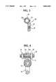
- FIG. 1shows a first embodiment of the spinal device according to the invention, partly in section in which one particular embodiment of an adapter is shown;
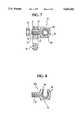
- FIG. 2shows a second embodiment of an adapter, partly in section for use in the spinal device of the invention
- FIG. 3shows a third embodiment of an adapter for use in the spinal device of the invention
- FIG. 4shows the connection of a threaded rod to the device of FIG. 1;
- FIG. 5shows a device similar to the device shown in FIG. 4, but including the adapter of FIG. 2;
- FIG. 6shows a device similar to the device shown in FIG. 4, but including the adapter of FIG. 3;
- FIG. 7shows a further embodiment of a spinal device according to the invention.
- FIG. 8shows a further embodiment of an adapter for use with the spinal device of the invention.
- FIG. 9shows the connection of the devices of FIGS. 7 and 8 to a threaded rod
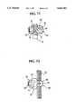
- FIG. 10shows a further embodiment of a spinal device according to the invention.
- FIG. 11shows the device of FIG. 10 in assembled and tightened condition
- FIG. 12shows the device of FIGS. 10 and 11 and including a threaded rod.
- FIG. 1shows a conventional pedicle screw 10 having a screw shank 12 and an annular head 14 including a circular opening 16, as well as serrated faces on opposite sides as seen at 18 and 20. Both ends of the opening 16 are enlarged in diameter.
- An adapter 22has a plate-shaped fastening portion 24 and a flat receiving portion 24a which is annular-shaped including a receiving opening 26a.
- the fastening portion 24has a threaded bore 26 and a serrated ring face 28.
- a head screw 30has a threaded portion 32 as well as a cylindrical portion 34 between the threaded portion 32 and a flange-like head 36.
- the head screw 30can be inserted in the opening 16 to be screwed with the threaded portion 32 into the threaded bore 26 to fixedly draw the adapter 22 towards the head 14 of the pedicle screw 10, wherein the serrations engage each other to prevent a rotation of the adapter 22 relative to the head 14 of the pedicle screw 10.
- the axis of the receiving opening 26aextends under a right angle to the axis of the threaded bore 26 and, because the fastening portion 24 is angularly located with respect to the receiving portion 24a, the latter is approximately located above the pedicle screw head 14, after the elements are mounted together.
- FIG. 2shows that the adapter 22 may be replaced by an adapter 40 having a fastening portion 24 including a threaded bore 26.
- the same reference numerals as in FIG. 1are used.
- the fastening portion 42is fork-like and thus includes a recess 44 which is open at the top and which is ringed by a serrated partial ring face 46.
- the adapter 50 of FIG. 3has a fastening portion 24 which is similar to that shown in FIGS. 1 and 2. Again, the receiving opening 52 is provided with an annular portion having an annular serration 54 at opposite faces.
- FIGS. 4 to 6show how the embodiments according to FIGS. 1 to 3 respectively cooperate with a threaded rod.
- the adapters 22, 40 or 50are fixed to the pedicle screw 10.
- FIG. 4shows how a threaded rod 56 extends through the opening 26a of the receiving portion 24a.
- the threaded rod 56is fixed to the adapter 22 by means of nuts 58, 60.
- the embodiment shown in FIG. 3utilizes a threaded rod 62 extending through the opening 26a.
- the threaded rod 62includes a flat 64 and carries washers 66, 68 which are non-rotatably, but axially slidably arranged on the rod 62.
- the washersinclude a serrated face 70, 72, cooperating with the serration 46 of the adapter 40.
- the washers 66 and 68may be secured with respect to the adapter 40 by means of the nuts 74, 76.
- the washers 66, 68prevent the rod from being moved out. Still further, they fix the rod 62 against rotation.
- FIG. 6utilizes a threaded rod 76 having a flattened portion also. Again, there are washers 66, 68 and nuts 74, 76 to secure the rod to the adapter 50 in an axial position and fixed against rotation.
- FIG. 7shows an adapter 80 having a threaded shank portion 82 which is inserted to the opening 16 of the head 14 of the pedicle screw 10 to be secured to the pedicle screw head 14 by means of a nut 84.
- the nuthas an axial flange engaging the enlarged portion of the opening 16.
- the receiving portion 86 of the adapter 80includes a receiving opening 88 provided for a threaded rod extending therethrough which opening is provided with a serrated annular face 90.
- the axis of the opening 88is located normal with respect to the opening 16 in the head 14.
- the receiving portion 86has a serrated annular face 92 cooperating with the serrated annular face 20 or, respectively 18 of the screw head 14 as may be seen in FIG. 7.
- FIG. 8shows an adapter 80a having a receiving portion 94 which is fork-shaped and has an annular face section 96 including a serration corresponding to the serrated annular face 90 shown in FIG. 7.
- the recesshas the reference numeral 98.
- the threaded rod 100is provided with threaded portions 102, 104 reversed with respect to each other, wherein a central hexagonal portion 106 is provided which may be engaged by a tool for rotating the rod 100 (for distracting or compressing).
- the portions 102, 104 of the rodare provided with flattened portions.
- Washers 108 having serrated head faces 110, respectively,are non-rotatably arranged on the threaded portion 104 to the right end of the rod, and may be secured to the correspondingly serrated annular faces 96 of the adapter 80a by means of nuts 112, 114.
- the adapter 80 shown in FIG. 9is connected to the rod 100 merely by means of the nuts 116, 118 having axial flanges cooperating with an enlarged portion within the opening 88.
- FIG. 10 and FIG. 11shows an adapter 120 having a receiving portion 122 including a through-bore 124, wherein the receiving portion 122 has a threaded bore 126 for receiving a fixing screw 128.
- the mounting portion of the adapter 120is defined by a threaded portion 130 which is inserted through the opening 16 of the screw head 14 to be provided with a serrated annular washer 134 and a securing nut 132.
- the threaded portion 130may be provided with a flattened portion cooperating with a corresponding flattened portion of the washer 134 to non-rotatably secure the adapter 120 to the head 14.
- the washer including its serration 136cooperates with the serration 18 of the head 14 of the pedicle screw 10.
- the receiving portion 122has a tapered side wall 138 cooperating with the side portion of the head 14.
- FIG. 12shows how the adapter 120 according to FIGS. 10 and 11 receives and secures a threaded rod 140.
- the fixingis provided by means of the fixing screw 128 and by tightening the threaded rod to the serration at the head 14 of the pedicle screw 10.
- the threaded rodalways extends under a right angle with respect to the axis of the opening in the pedicle screw head.
- the adapteris shaped such that the threaded rod is located relatively close to the head of the pedicle screw to provide a rather compact arrangement.
Landscapes
- Health & Medical Sciences (AREA)
- Orthopedic Medicine & Surgery (AREA)
- Life Sciences & Earth Sciences (AREA)
- Neurology (AREA)
- Surgery (AREA)
- Heart & Thoracic Surgery (AREA)
- General Health & Medical Sciences (AREA)
- Biomedical Technology (AREA)
- Nuclear Medicine, Radiotherapy & Molecular Imaging (AREA)
- Medical Informatics (AREA)
- Molecular Biology (AREA)
- Animal Behavior & Ethology (AREA)
- Engineering & Computer Science (AREA)
- Public Health (AREA)
- Veterinary Medicine (AREA)
- Surgical Instruments (AREA)
- Orthopedics, Nursing, And Contraception (AREA)
- Prostheses (AREA)
- Thermotherapy And Cooling Therapy Devices (AREA)
Abstract
Description
Claims (6)
Applications Claiming Priority (2)
| Application Number | Priority Date | Filing Date | Title |
|---|---|---|---|
| DE9409123UDE9409123U1 (en) | 1994-06-04 | 1994-06-04 | Device for stabilizing or compressing or distracting sections of the spine |
| DE9409123U | 1994-06-04 |
Publications (1)
| Publication Number | Publication Date |
|---|---|
| US5643262Atrue US5643262A (en) | 1997-07-01 |
Family
ID=6909474
Family Applications (1)
| Application Number | Title | Priority Date | Filing Date |
|---|---|---|---|
| US08/457,635Expired - LifetimeUS5643262A (en) | 1994-06-04 | 1995-06-01 | Device for spinal column |
Country Status (5)
| Country | Link |
|---|---|
| US (1) | US5643262A (en) |
| EP (2) | EP0685207B1 (en) |
| JP (1) | JP2671974B2 (en) |
| CA (1) | CA2150895C (en) |
| DE (3) | DE9409123U1 (en) |
Cited By (44)
| Publication number | Priority date | Publication date | Assignee | Title |
|---|---|---|---|---|
| US6183473B1 (en)* | 1999-04-21 | 2001-02-06 | Richard B Ashman | Variable angle connection assembly for a spinal implant system |
| US6234705B1 (en) | 1999-04-06 | 2001-05-22 | Synthes (Usa) | Transconnector for coupling spinal rods |
| US6283967B1 (en) | 1999-12-17 | 2001-09-04 | Synthes (U.S.A.) | Transconnector for coupling spinal rods |
| US6387097B1 (en)* | 1997-05-16 | 2002-05-14 | Scient'x Societe A Responsabilite Limitee | Implant for osteosynthesis device with hook |
| US6409729B1 (en) | 1998-05-19 | 2002-06-25 | Synthes (Usa) | Clamp assembly for an external fixation system |
| US20020107573A1 (en)* | 1999-03-07 | 2002-08-08 | Discure Ltd. | Method and apparatus for computerized surgery |
| US6471703B1 (en)* | 1999-04-21 | 2002-10-29 | Sdgi Holdings, Inc. | Variable angle connection assembly for a spinal implant system |
| US6551318B1 (en)* | 2000-07-26 | 2003-04-22 | Stahurski Consulting Inc. | Spinal column retaining apparatus |
| US20040111091A1 (en)* | 2002-05-21 | 2004-06-10 | James Ogilvie | Reduction cable and bone anchor |
| US6783527B2 (en)* | 2001-10-30 | 2004-08-31 | Sdgi Holdings, Inc. | Flexible spinal stabilization system and method |
| US20050234450A1 (en)* | 2004-04-15 | 2005-10-20 | Barker B T | Transfer ring for offset tapered 3D connector |
| US20050277931A1 (en)* | 2004-06-09 | 2005-12-15 | Spinal Generations, Llc | Spinal fixation system |
| US20050277923A1 (en)* | 2004-06-09 | 2005-12-15 | Sweeney Patrick J | Spinal fixation system |
| US20060036252A1 (en)* | 2004-08-12 | 2006-02-16 | Baynham Bret O | Polyaxial screw |
| US20060195096A1 (en)* | 2005-02-09 | 2006-08-31 | David Lee | Bone fixation apparatus |
| US20060271051A1 (en)* | 2003-10-22 | 2006-11-30 | Pioneer Laboratories, Inc. | Crossllink for securing spinal rods |
| US20070055239A1 (en)* | 2004-06-09 | 2007-03-08 | Spinal Generations, Llc | Spinal fixation system |
| US20070118123A1 (en)* | 2005-11-21 | 2007-05-24 | Strausbaugh William L | Polyaxial bone anchors with increased angulation |
| US20080015588A1 (en)* | 2006-07-11 | 2008-01-17 | Hawkes David T | Transverse Connector |
| US20090076549A1 (en)* | 2007-09-17 | 2009-03-19 | Warsaw Orthopedic, Inc. | Orthopedic implant system |
| US8092494B2 (en) | 2004-01-13 | 2012-01-10 | Life Spine, Inc. | Pedicle screw constructs for spine fixation systems |
| US8328807B2 (en) | 2008-07-09 | 2012-12-11 | Icon Orthopaedic Concepts, Llc | Ankle arthrodesis nail and outrigger assembly |
| US8388660B1 (en) | 2006-08-01 | 2013-03-05 | Samy Abdou | Devices and methods for superior fixation of orthopedic devices onto the vertebral column |
| US8414584B2 (en) | 2008-07-09 | 2013-04-09 | Icon Orthopaedic Concepts, Llc | Ankle arthrodesis nail and outrigger assembly |
| US8663287B2 (en) | 2006-01-10 | 2014-03-04 | Life Spine, Inc. | Pedicle screw constructs and spinal rod attachment assemblies |
| US8979459B2 (en) | 2012-11-19 | 2015-03-17 | Infastech Intellectual Properties Pte. Ltd. | Combination hanger fastener |
| US9005249B2 (en) | 2011-07-11 | 2015-04-14 | Life Spine, Inc. | Spinal rod connector assembly |
| US9907582B1 (en) | 2011-04-25 | 2018-03-06 | Nuvasive, Inc. | Minimally invasive spinal fixation system and related methods |
| US9974571B2 (en) | 2008-09-12 | 2018-05-22 | DePuy Synthes Products, Inc. | Spinal stabilizing and guiding fixation system |
| US10105163B2 (en) | 2009-04-15 | 2018-10-23 | DePuy Synthes Products, Inc. | Revision connector for spinal constructs |
| US10136923B2 (en) | 2007-07-20 | 2018-11-27 | DePuy Synthes Products, Inc. | Polyaxial bone fixation element |
| US10154859B2 (en) | 2008-09-29 | 2018-12-18 | DePuy Synthes Products, Inc. | Polyaxial bottom-loading screw and rod assembly |
| US10405892B2 (en) | 2008-11-03 | 2019-09-10 | DePuy Synthes Products, Inc. | Uni-planer bone fixation assembly |
| US10543107B2 (en) | 2009-12-07 | 2020-01-28 | Samy Abdou | Devices and methods for minimally invasive spinal stabilization and instrumentation |
| US10548740B1 (en) | 2016-10-25 | 2020-02-04 | Samy Abdou | Devices and methods for vertebral bone realignment |
| US10575961B1 (en) | 2011-09-23 | 2020-03-03 | Samy Abdou | Spinal fixation devices and methods of use |
| US10695105B2 (en) | 2012-08-28 | 2020-06-30 | Samy Abdou | Spinal fixation devices and methods of use |
| US10857003B1 (en) | 2015-10-14 | 2020-12-08 | Samy Abdou | Devices and methods for vertebral stabilization |
| US10918498B2 (en) | 2004-11-24 | 2021-02-16 | Samy Abdou | Devices and methods for inter-vertebral orthopedic device placement |
| US10973648B1 (en) | 2016-10-25 | 2021-04-13 | Samy Abdou | Devices and methods for vertebral bone realignment |
| US11006978B2 (en) | 2009-06-17 | 2021-05-18 | DePuy Synthes Products, Inc. | Revision connector for spinal constructs |
| US11006982B2 (en) | 2012-02-22 | 2021-05-18 | Samy Abdou | Spinous process fixation devices and methods of use |
| US11173040B2 (en) | 2012-10-22 | 2021-11-16 | Cogent Spine, LLC | Devices and methods for spinal stabilization and instrumentation |
| US11179248B2 (en) | 2018-10-02 | 2021-11-23 | Samy Abdou | Devices and methods for spinal implantation |
Families Citing this family (3)
| Publication number | Priority date | Publication date | Assignee | Title |
|---|---|---|---|---|
| DE29600784U1 (en)* | 1996-01-18 | 1996-03-21 | Howmedica GmbH, 24232 Schönkirchen | Connecting element for a stabilization system for a human spine |
| US6001098A (en)* | 1997-01-17 | 1999-12-14 | Howmedica Gmbh | Connecting element for spinal stabilizing system |
| CN112576603A (en)* | 2020-12-30 | 2021-03-30 | 河南航天精工制造有限公司 | Interlocking bolt |
Citations (16)
| Publication number | Priority date | Publication date | Assignee | Title |
|---|---|---|---|---|
| FR2289164A1 (en)* | 1974-11-04 | 1976-05-28 | Tornier Rene | Device for treatment of scoliosis - has rod with hook movable along it away from fixed hook |
| GB2131300A (en)* | 1982-12-01 | 1984-06-20 | Cannon Edwards Charles | Spinal compression/distraction hooks |
| US4611580A (en)* | 1983-11-23 | 1986-09-16 | Henry Ford Hospital | Intervertebral body stabilization |
| DE3306657C2 (en)* | 1983-02-25 | 1986-12-11 | Fa. Heinrich C. Ulrich, 7900 Ulm | Spine correction implant with a distraction rod |
| EP0159007B1 (en)* | 1984-04-16 | 1989-01-11 | Kluger, Patrick, Dr. med. | Apparatus for the treatment of the spinal column |
| DE8802112U1 (en)* | 1988-02-18 | 1989-07-13 | Howmedica GmbH, 2314 Schönkirchen | Support device for the human spine |
| WO1990009156A1 (en)* | 1989-02-09 | 1990-08-23 | Vignaud Jean Louis | A supporting device for the spinal column |
| US4987892A (en)* | 1989-04-04 | 1991-01-29 | Krag Martin H | Spinal fixation device |
| WO1991001115A1 (en)* | 1989-07-20 | 1991-02-07 | Lutz Biedermann | Pedicle screw and pedicle-screw holder |
| EP0425783A1 (en)* | 1989-10-30 | 1991-05-08 | Synthes AG, Chur | Pedicle screw clamp |
| US5053034A (en)* | 1990-08-03 | 1991-10-01 | Sven Olerud | Spinal joint |
| EP0553424A1 (en)* | 1992-01-30 | 1993-08-04 | Acromed Corporation | Spinal column retaining apparatus |
| WO1993015697A1 (en)* | 1992-02-18 | 1993-08-19 | Danek Medical, Inc. | Variable angle screw for spinal implant system |
| EP0558883A1 (en)* | 1992-03-02 | 1993-09-08 | Howmedica GmbH | Apparatus for bracing a plurality of vertebras of the human spine |
| US5387212A (en)* | 1993-01-26 | 1995-02-07 | Yuan; Hansen A. | Vertebral locking and retrieving system with central locking rod |
| US5468241A (en)* | 1988-02-18 | 1995-11-21 | Howmedica Gmbh | Support device for the human vertebral column |
Family Cites Families (4)
| Publication number | Priority date | Publication date | Assignee | Title |
|---|---|---|---|---|
| DE3219575A1 (en)* | 1982-05-25 | 1983-12-01 | Patrick Dr.med. 3590 Bad Wildungen Kluger | Implant system for correction of the position and stabilisation of the spine |
| DE8703022U1 (en)* | 1987-02-27 | 1987-04-30 | Weber, Gerhard, 7238 Oberndorf | Internal fixator |
| CH683963A5 (en)* | 1988-06-10 | 1994-06-30 | Synthes Ag | Internal fixation. |
| DE9004240U1 (en) | 1990-04-11 | 1991-08-08 | Waldemar Link Gmbh & Co, 2000 Hamburg | Bone surgical holder |
- 1994
- 1994-06-04DEDE9409123Upatent/DE9409123U1/ennot_activeExpired - Lifetime
- 1995
- 1995-05-06DEDE69529631Tpatent/DE69529631T2/ennot_activeExpired - Lifetime
- 1995-05-06DEDE69526388Tpatent/DE69526388T2/ennot_activeExpired - Lifetime
- 1995-05-06EPEP95106886Apatent/EP0685207B1/ennot_activeExpired - Lifetime
- 1995-05-06EPEP01103156Apatent/EP1101449B1/ennot_activeExpired - Lifetime
- 1995-05-30JPJP7132061Apatent/JP2671974B2/ennot_activeExpired - Lifetime
- 1995-06-01USUS08/457,635patent/US5643262A/ennot_activeExpired - Lifetime
- 1995-06-02CACA002150895Apatent/CA2150895C/ennot_activeExpired - Lifetime
Patent Citations (17)
| Publication number | Priority date | Publication date | Assignee | Title |
|---|---|---|---|---|
| FR2289164A1 (en)* | 1974-11-04 | 1976-05-28 | Tornier Rene | Device for treatment of scoliosis - has rod with hook movable along it away from fixed hook |
| GB2131300A (en)* | 1982-12-01 | 1984-06-20 | Cannon Edwards Charles | Spinal compression/distraction hooks |
| DE3306657C2 (en)* | 1983-02-25 | 1986-12-11 | Fa. Heinrich C. Ulrich, 7900 Ulm | Spine correction implant with a distraction rod |
| US4611580A (en)* | 1983-11-23 | 1986-09-16 | Henry Ford Hospital | Intervertebral body stabilization |
| EP0159007B1 (en)* | 1984-04-16 | 1989-01-11 | Kluger, Patrick, Dr. med. | Apparatus for the treatment of the spinal column |
| US5468241A (en)* | 1988-02-18 | 1995-11-21 | Howmedica Gmbh | Support device for the human vertebral column |
| DE8802112U1 (en)* | 1988-02-18 | 1989-07-13 | Howmedica GmbH, 2314 Schönkirchen | Support device for the human spine |
| WO1990009156A1 (en)* | 1989-02-09 | 1990-08-23 | Vignaud Jean Louis | A supporting device for the spinal column |
| US4987892A (en)* | 1989-04-04 | 1991-01-29 | Krag Martin H | Spinal fixation device |
| WO1991001115A1 (en)* | 1989-07-20 | 1991-02-07 | Lutz Biedermann | Pedicle screw and pedicle-screw holder |
| EP0425783A1 (en)* | 1989-10-30 | 1991-05-08 | Synthes AG, Chur | Pedicle screw clamp |
| US5053034A (en)* | 1990-08-03 | 1991-10-01 | Sven Olerud | Spinal joint |
| EP0553424A1 (en)* | 1992-01-30 | 1993-08-04 | Acromed Corporation | Spinal column retaining apparatus |
| WO1993015697A1 (en)* | 1992-02-18 | 1993-08-19 | Danek Medical, Inc. | Variable angle screw for spinal implant system |
| US5261909A (en)* | 1992-02-18 | 1993-11-16 | Danek Medical, Inc. | Variable angle screw for spinal implant system |
| EP0558883A1 (en)* | 1992-03-02 | 1993-09-08 | Howmedica GmbH | Apparatus for bracing a plurality of vertebras of the human spine |
| US5387212A (en)* | 1993-01-26 | 1995-02-07 | Yuan; Hansen A. | Vertebral locking and retrieving system with central locking rod |
Non-Patent Citations (1)
| Title |
|---|
| German Search Report dated Sep. 6, 1994.* |
Cited By (115)
| Publication number | Priority date | Publication date | Assignee | Title |
|---|---|---|---|---|
| US7497868B2 (en) | 1995-09-04 | 2009-03-03 | Active Implants Corporation | Method and apparatus for computerized surgery |
| US20070093689A1 (en)* | 1995-09-04 | 2007-04-26 | Active Implants Corporation | Method and apparatus for computerized surgery |
| US20050177239A1 (en)* | 1995-09-04 | 2005-08-11 | Amiram Steinberg | Method and apparatus for computerized surgery |
| US20080071374A1 (en)* | 1995-09-04 | 2008-03-20 | Active Implants Corporation | Method and apparatus for computerized surgery |
| US7491219B2 (en) | 1995-09-04 | 2009-02-17 | Active Implants Corporation | Method and apparatus for computerized surgery |
| US6387097B1 (en)* | 1997-05-16 | 2002-05-14 | Scient'x Societe A Responsabilite Limitee | Implant for osteosynthesis device with hook |
| US6409729B1 (en) | 1998-05-19 | 2002-06-25 | Synthes (Usa) | Clamp assembly for an external fixation system |
| US7338526B2 (en) | 1999-03-07 | 2008-03-04 | Active Implants Corporation | Method and apparatus for computerized surgery |
| US20020107573A1 (en)* | 1999-03-07 | 2002-08-08 | Discure Ltd. | Method and apparatus for computerized surgery |
| US9827109B2 (en) | 1999-03-07 | 2017-11-28 | Nuvasive, Inc. | Methods and apparatus for performing spine surgery |
| US9017313B2 (en) | 1999-03-07 | 2015-04-28 | Nuvasive, Inc. | Method and apparatus for computerized surgery |
| US9668875B2 (en) | 1999-03-07 | 2017-06-06 | Nuvasive, Inc. | Method and apparatus for computerized surgery |
| US6234705B1 (en) | 1999-04-06 | 2001-05-22 | Synthes (Usa) | Transconnector for coupling spinal rods |
| US6306137B2 (en) | 1999-04-06 | 2001-10-23 | Synthes (U.S.A.) | Transconnector for coupling spinal rods |
| US6402749B1 (en) | 1999-04-21 | 2002-06-11 | Sdgi Holdings, Inc. | Variable angle connection assembly for a spinal implant system |
| US6471703B1 (en)* | 1999-04-21 | 2002-10-29 | Sdgi Holdings, Inc. | Variable angle connection assembly for a spinal implant system |
| US6183473B1 (en)* | 1999-04-21 | 2001-02-06 | Richard B Ashman | Variable angle connection assembly for a spinal implant system |
| US6283967B1 (en) | 1999-12-17 | 2001-09-04 | Synthes (U.S.A.) | Transconnector for coupling spinal rods |
| US6736817B2 (en) | 1999-12-17 | 2004-05-18 | Thomas N. Troxell | Transconnector for coupling spinal rods |
| US6551318B1 (en)* | 2000-07-26 | 2003-04-22 | Stahurski Consulting Inc. | Spinal column retaining apparatus |
| US7828826B2 (en) | 2001-10-30 | 2010-11-09 | Warsaw Orthopedic, Inc. | Flexible spinal stabilization system and method |
| US6783527B2 (en)* | 2001-10-30 | 2004-08-31 | Sdgi Holdings, Inc. | Flexible spinal stabilization system and method |
| US20060122599A1 (en)* | 2001-10-30 | 2006-06-08 | Sdgi Holdings, Inc. | Flexible spinal stabilization system and method |
| US10206715B2 (en) | 2001-10-30 | 2019-02-19 | Warsaw Orthopedic, Inc. | Flexible spinal stabilization system and method |
| US10898230B2 (en) | 2001-10-30 | 2021-01-26 | Warsaw Orthopedic, Inc. | Flexible spinal stabilization system and method |
| US8142483B2 (en) | 2001-10-30 | 2012-03-27 | Warsaw Orthopedic, Inc. | Flexible spinal stabilization system and method |
| US20100331890A1 (en)* | 2001-10-30 | 2010-12-30 | Drewry Troy D | Flexible spinal stabilization system and method |
| US9358045B2 (en) | 2001-10-30 | 2016-06-07 | Warsaw Orthopedic, Inc. | Flexible spinal stabilization system and method |
| US7338490B2 (en) | 2002-05-21 | 2008-03-04 | Warsaw Orthopedic, Inc. | Reduction cable and bone anchor |
| US20040111091A1 (en)* | 2002-05-21 | 2004-06-10 | James Ogilvie | Reduction cable and bone anchor |
| US7927355B2 (en) | 2003-10-22 | 2011-04-19 | Pioneer Surgical Technology, Inc. | Crosslink for securing spinal rods |
| US7744633B2 (en) | 2003-10-22 | 2010-06-29 | Pioneer Surgical Technology, Inc. | Crosslink for securing spinal rods |
| US20060271051A1 (en)* | 2003-10-22 | 2006-11-30 | Pioneer Laboratories, Inc. | Crossllink for securing spinal rods |
| US8092494B2 (en) | 2004-01-13 | 2012-01-10 | Life Spine, Inc. | Pedicle screw constructs for spine fixation systems |
| US20050234450A1 (en)* | 2004-04-15 | 2005-10-20 | Barker B T | Transfer ring for offset tapered 3D connector |
| US7377922B2 (en)* | 2004-04-15 | 2008-05-27 | Warsaw Orthopedic, Inc. | Transfer ring for offset tapered 3D connector |
| US9168151B2 (en) | 2004-06-09 | 2015-10-27 | Life Spine, Inc. | Spinal fixation system |
| US7744635B2 (en)* | 2004-06-09 | 2010-06-29 | Spinal Generations, Llc | Spinal fixation system |
| US20110004251A1 (en)* | 2004-06-09 | 2011-01-06 | Life Spine, Inc. | Spinal fixation system |
| US20070055239A1 (en)* | 2004-06-09 | 2007-03-08 | Spinal Generations, Llc | Spinal fixation system |
| US7938848B2 (en) | 2004-06-09 | 2011-05-10 | Life Spine, Inc. | Spinal fixation system |
| US8021398B2 (en)* | 2004-06-09 | 2011-09-20 | Life Spine, Inc. | Spinal fixation system |
| US20050277931A1 (en)* | 2004-06-09 | 2005-12-15 | Spinal Generations, Llc | Spinal fixation system |
| US8617209B2 (en) | 2004-06-09 | 2013-12-31 | Life Spine, Inc. | Spinal fixation system |
| US20060149245A1 (en)* | 2004-06-09 | 2006-07-06 | Spinal Generations, Llc | Bone fixation system |
| US20050277923A1 (en)* | 2004-06-09 | 2005-12-15 | Sweeney Patrick J | Spinal fixation system |
| US20060036252A1 (en)* | 2004-08-12 | 2006-02-16 | Baynham Bret O | Polyaxial screw |
| US7186255B2 (en) | 2004-08-12 | 2007-03-06 | Atlas Spine, Inc. | Polyaxial screw |
| US10918498B2 (en) | 2004-11-24 | 2021-02-16 | Samy Abdou | Devices and methods for inter-vertebral orthopedic device placement |
| US11992423B2 (en) | 2004-11-24 | 2024-05-28 | Samy Abdou | Devices and methods for inter-vertebral orthopedic device placement |
| US11096799B2 (en) | 2004-11-24 | 2021-08-24 | Samy Abdou | Devices and methods for inter-vertebral orthopedic device placement |
| US20060195096A1 (en)* | 2005-02-09 | 2006-08-31 | David Lee | Bone fixation apparatus |
| US7896905B2 (en)* | 2005-02-09 | 2011-03-01 | David Lee | Bone fixation apparatus |
| US10595908B2 (en) | 2005-11-21 | 2020-03-24 | DePuy Sythes Products, Inc. | Polaxial bone anchors with increased angulation |
| US9848918B2 (en) | 2005-11-21 | 2017-12-26 | DePuy Synthes Products, Inc. | Polyaxial bone anchors with increased angulation |
| US11432850B2 (en) | 2005-11-21 | 2022-09-06 | DePuy Synthes Products, Inc. | Polyaxial bone anchors with increased angulation |
| US8679162B2 (en) | 2005-11-21 | 2014-03-25 | DePuy Synthes Products, LLC | Polyaxial bone anchors with increased angulation |
| US8100946B2 (en) | 2005-11-21 | 2012-01-24 | Synthes Usa, Llc | Polyaxial bone anchors with increased angulation |
| US20070118123A1 (en)* | 2005-11-21 | 2007-05-24 | Strausbaugh William L | Polyaxial bone anchors with increased angulation |
| US9504498B2 (en) | 2005-11-21 | 2016-11-29 | DePuy Synthes Products, Inc. | Polyaxial bone anchors with increased angulation |
| US8663287B2 (en) | 2006-01-10 | 2014-03-04 | Life Spine, Inc. | Pedicle screw constructs and spinal rod attachment assemblies |
| US20080015588A1 (en)* | 2006-07-11 | 2008-01-17 | Hawkes David T | Transverse Connector |
| US7842071B2 (en) | 2006-07-11 | 2010-11-30 | Pioneer Surgical Technology, Inc. | Transverse connector |
| US8388660B1 (en) | 2006-08-01 | 2013-03-05 | Samy Abdou | Devices and methods for superior fixation of orthopedic devices onto the vertebral column |
| US11998246B2 (en) | 2007-07-20 | 2024-06-04 | DePuy Synthes Products, Inc. | Polyaxial bone fixation element |
| US10898234B2 (en) | 2007-07-20 | 2021-01-26 | DePuy Synthes Products, Inc. | Polyaxial bone fixation element |
| US11357550B2 (en) | 2007-07-20 | 2022-06-14 | DePuy Synthes Products, Inc. | Polyaxial bone fixation element |
| US10136923B2 (en) | 2007-07-20 | 2018-11-27 | DePuy Synthes Products, Inc. | Polyaxial bone fixation element |
| US11819247B2 (en) | 2007-07-20 | 2023-11-21 | DePuy Synthes Products, Inc. | Polyaxial bone fixation element |
| US20090076549A1 (en)* | 2007-09-17 | 2009-03-19 | Warsaw Orthopedic, Inc. | Orthopedic implant system |
| US8328807B2 (en) | 2008-07-09 | 2012-12-11 | Icon Orthopaedic Concepts, Llc | Ankle arthrodesis nail and outrigger assembly |
| US9226783B2 (en) | 2008-07-09 | 2016-01-05 | Icon Orthopaedic Concepts, Llc | Ankle arthrodesis nail and outrigger assembly |
| US8414584B2 (en) | 2008-07-09 | 2013-04-09 | Icon Orthopaedic Concepts, Llc | Ankle arthrodesis nail and outrigger assembly |
| US11890037B2 (en) | 2008-09-12 | 2024-02-06 | DePuy Synthes Products, Inc. | Spinal stabilizing and guiding fixation system |
| US9974571B2 (en) | 2008-09-12 | 2018-05-22 | DePuy Synthes Products, Inc. | Spinal stabilizing and guiding fixation system |
| US11129648B2 (en) | 2008-09-12 | 2021-09-28 | DePuy Synthes Products, Inc. | Spinal stabilizing and guiding fixation system |
| US10154859B2 (en) | 2008-09-29 | 2018-12-18 | DePuy Synthes Products, Inc. | Polyaxial bottom-loading screw and rod assembly |
| US10709479B2 (en) | 2008-09-29 | 2020-07-14 | DePuy Synthes Products, Inc. | Polyaxial bottom-loading screw and rod assembly |
| US11484348B2 (en) | 2008-11-03 | 2022-11-01 | DePuy Synthes Products, Inc. | Uni-planer bone fixation assembly |
| US10405892B2 (en) | 2008-11-03 | 2019-09-10 | DePuy Synthes Products, Inc. | Uni-planer bone fixation assembly |
| US10105163B2 (en) | 2009-04-15 | 2018-10-23 | DePuy Synthes Products, Inc. | Revision connector for spinal constructs |
| US12064145B2 (en) | 2009-04-15 | 2024-08-20 | DePuy Synthes Products, Inc. | Revision connector for spinal constructs |
| US11020152B2 (en) | 2009-04-15 | 2021-06-01 | DePuy Synthes Products, Inc. | Revision connector for spinal constructs |
| US11006978B2 (en) | 2009-06-17 | 2021-05-18 | DePuy Synthes Products, Inc. | Revision connector for spinal constructs |
| US12089877B2 (en) | 2009-06-17 | 2024-09-17 | DePuy Synthes Products, Inc. | Revision connector for spinal constructs |
| US10610380B2 (en) | 2009-12-07 | 2020-04-07 | Samy Abdou | Devices and methods for minimally invasive spinal stabilization and instrumentation |
| US10543107B2 (en) | 2009-12-07 | 2020-01-28 | Samy Abdou | Devices and methods for minimally invasive spinal stabilization and instrumentation |
| US11918486B2 (en) | 2009-12-07 | 2024-03-05 | Samy Abdou | Devices and methods for minimally invasive spinal stabilization and instrumentation |
| US10945861B2 (en) | 2009-12-07 | 2021-03-16 | Samy Abdou | Devices and methods for minimally invasive spinal stabilization and instrumentation |
| US10857004B2 (en) | 2009-12-07 | 2020-12-08 | Samy Abdou | Devices and methods for minimally invasive spinal stabilization and instrumentation |
| US12357350B2 (en) | 2011-04-25 | 2025-07-15 | Nuvasive, Inc. | Minimally invasive spinal fixation system and related methods |
| US11596453B2 (en) | 2011-04-25 | 2023-03-07 | Nuvasive, Inc. | Minimally invasive spinal fixation system |
| US9907582B1 (en) | 2011-04-25 | 2018-03-06 | Nuvasive, Inc. | Minimally invasive spinal fixation system and related methods |
| US10716600B1 (en) | 2011-04-25 | 2020-07-21 | Nuvasive, Inc. | Minimally invasive spinal fixation system |
| US9005249B2 (en) | 2011-07-11 | 2015-04-14 | Life Spine, Inc. | Spinal rod connector assembly |
| US11324608B2 (en) | 2011-09-23 | 2022-05-10 | Samy Abdou | Spinal fixation devices and methods of use |
| US10575961B1 (en) | 2011-09-23 | 2020-03-03 | Samy Abdou | Spinal fixation devices and methods of use |
| US11517449B2 (en) | 2011-09-23 | 2022-12-06 | Samy Abdou | Spinal fixation devices and methods of use |
| US12167973B2 (en) | 2011-09-23 | 2024-12-17 | Samy Abdou | Spinal fixation devices and methods of use |
| US11006982B2 (en) | 2012-02-22 | 2021-05-18 | Samy Abdou | Spinous process fixation devices and methods of use |
| US11839413B2 (en) | 2012-02-22 | 2023-12-12 | Samy Abdou | Spinous process fixation devices and methods of use |
| US10695105B2 (en) | 2012-08-28 | 2020-06-30 | Samy Abdou | Spinal fixation devices and methods of use |
| US11559336B2 (en) | 2012-08-28 | 2023-01-24 | Samy Abdou | Spinal fixation devices and methods of use |
| US11918483B2 (en) | 2012-10-22 | 2024-03-05 | Cogent Spine Llc | Devices and methods for spinal stabilization and instrumentation |
| US11173040B2 (en) | 2012-10-22 | 2021-11-16 | Cogent Spine, LLC | Devices and methods for spinal stabilization and instrumentation |
| US8979459B2 (en) | 2012-11-19 | 2015-03-17 | Infastech Intellectual Properties Pte. Ltd. | Combination hanger fastener |
| US11246718B2 (en) | 2015-10-14 | 2022-02-15 | Samy Abdou | Devices and methods for vertebral stabilization |
| US10857003B1 (en) | 2015-10-14 | 2020-12-08 | Samy Abdou | Devices and methods for vertebral stabilization |
| US11752008B1 (en) | 2016-10-25 | 2023-09-12 | Samy Abdou | Devices and methods for vertebral bone realignment |
| US10744000B1 (en) | 2016-10-25 | 2020-08-18 | Samy Abdou | Devices and methods for vertebral bone realignment |
| US10548740B1 (en) | 2016-10-25 | 2020-02-04 | Samy Abdou | Devices and methods for vertebral bone realignment |
| US10973648B1 (en) | 2016-10-25 | 2021-04-13 | Samy Abdou | Devices and methods for vertebral bone realignment |
| US11259935B1 (en) | 2016-10-25 | 2022-03-01 | Samy Abdou | Devices and methods for vertebral bone realignment |
| US11058548B1 (en) | 2016-10-25 | 2021-07-13 | Samy Abdou | Devices and methods for vertebral bone realignment |
| US11179248B2 (en) | 2018-10-02 | 2021-11-23 | Samy Abdou | Devices and methods for spinal implantation |
Also Published As
| Publication number | Publication date |
|---|---|
| DE9409123U1 (en) | 1994-09-01 |
| DE69529631D1 (en) | 2003-03-20 |
| EP0685207A1 (en) | 1995-12-06 |
| EP1101449B1 (en) | 2003-02-12 |
| CA2150895C (en) | 1999-10-19 |
| DE69526388T2 (en) | 2002-11-28 |
| JPH07328027A (en) | 1995-12-19 |
| DE69526388D1 (en) | 2002-05-23 |
| DE69529631T2 (en) | 2003-06-26 |
| EP1101449A1 (en) | 2001-05-23 |
| CA2150895A1 (en) | 1995-12-05 |
| JP2671974B2 (en) | 1997-11-05 |
| EP0685207B1 (en) | 2002-04-17 |
Similar Documents
| Publication | Publication Date | Title |
|---|---|---|
| US5643262A (en) | Device for spinal column | |
| US6248104B1 (en) | Apparatus for osteosynthesis comprising a connector of the spinal pin and the anchoring elements | |
| CA2133484C (en) | Posterior spinal implant | |
| US9895173B2 (en) | Element with a shank and a holding element connected to it for connecting to a rod | |
| EP1330198B1 (en) | Connector for spinal rod and vertebral anchor | |
| US6673074B2 (en) | Apparatus for retaining bone portions in a desired spatial relationship | |
| US5443467A (en) | Bone screw | |
| US7666210B2 (en) | Connection system between a spinal rod and a transverse bar | |
| US6001098A (en) | Connecting element for spinal stabilizing system | |
| US6409729B1 (en) | Clamp assembly for an external fixation system | |
| CA2116423C (en) | Device for setting a spline | |
| US6039738A (en) | Fastener | |
| CA2109457C (en) | Osteosynthesis device for spinal consolidation | |
| KR100663228B1 (en) | Bone screw | |
| US6423064B1 (en) | Orthopaedic screw variable angle connection to a longitudinal support | |
| US6027533A (en) | Device for fixating and adjusting the positions of vertebrae in vertebral surgical operations | |
| US7223268B2 (en) | Locking device for securing a rod-shaped element in a holding element connected to a shank | |
| EP0955929A4 (en) | A variable length and angle cross-link device | |
| US20070055238A1 (en) | Screw | |
| US20020143327A1 (en) | Transverse connector for use in spinal corrective surgery | |
| JP2003204971A (en) | Locking device and element | |
| JPH11253454A (en) | Screw turning position determining mechanism | |
| CA2084130A1 (en) | Spinal column retaining apparatus | |
| EP0077681A2 (en) | Bone fixation screws | |
| AU713325B2 (en) | Fastener |
Legal Events
| Date | Code | Title | Description |
|---|---|---|---|
| AS | Assignment | Owner name:HOWMEDICA GMBH, GERMANY Free format text:ASSIGNMENT OF ASSIGNORS INTEREST;ASSIGNORS:METZ-STAVENHAGEN, PETER;ROBIONECK, BERND;REEL/FRAME:007701/0981;SIGNING DATES FROM 19950821 TO 19950828 | |
| STCF | Information on status: patent grant | Free format text:PATENTED CASE | |
| FEPP | Fee payment procedure | Free format text:PAYOR NUMBER ASSIGNED (ORIGINAL EVENT CODE: ASPN); ENTITY STATUS OF PATENT OWNER: LARGE ENTITY | |
| FPAY | Fee payment | Year of fee payment:4 | |
| REMI | Maintenance fee reminder mailed | ||
| AS | Assignment | Owner name:STRYKER TRAUMA GMBH, CORPORATION OF REPUBLIC OF GE Free format text:CHANGE OF NAME;ASSIGNOR:HOWMEDICA GMBH, CORPORATION OF REPUBLIC OFGERMANY;REEL/FRAME:011796/0878 Effective date:19991118 | |
| FPAY | Fee payment | Year of fee payment:8 | |
| FPAY | Fee payment | Year of fee payment:12 | |
| AS | Assignment | Owner name:STRYKER EUROPEAN HOLDINGS I, LLC, MICHIGAN Free format text:NUNC PRO TUNC ASSIGNMENT;ASSIGNOR:STRYKER EUROPEAN HOLDINGS VI, LLC;REEL/FRAME:037153/0391 Effective date:20151008 Owner name:STRYKER EUROPEAN HOLDINGS VI, LLC, MICHIGAN Free format text:NUNC PRO TUNC ASSIGNMENT;ASSIGNOR:STRYKER TRAUMA GMBH;REEL/FRAME:037152/0863 Effective date:20151008 | |
| AS | Assignment | Owner name:STRYKER EUROPEAN OPERATIONS HOLDINGS LLC, MICHIGAN Free format text:CHANGE OF NAME;ASSIGNOR:STRYKER EUROPEAN HOLDINGS III, LLC;REEL/FRAME:052860/0716 Effective date:20190226 Owner name:STRYKER EUROPEAN HOLDINGS III, LLC, DELAWARE Free format text:NUNC PRO TUNC ASSIGNMENT;ASSIGNOR:STRYKER EUROPEAN HOLDINGS I, LLC;REEL/FRAME:052861/0001 Effective date:20200519 |