US5643251A - Fibert optic guide wire and support catheter therefor - Google Patents
Fibert optic guide wire and support catheter thereforDownload PDFInfo
- Publication number
- US5643251A US5643251AUS08/539,079US53907995AUS5643251AUS 5643251 AUS5643251 AUS 5643251AUS 53907995 AUS53907995 AUS 53907995AUS 5643251 AUS5643251 AUS 5643251A
- Authority
- US
- United States
- Prior art keywords
- guide wire
- catheter
- distal end
- tube
- fiber bundle
- Prior art date
- Legal status (The legal status is an assumption and is not a legal conclusion. Google has not performed a legal analysis and makes no representation as to the accuracy of the status listed.)
- Expired - Lifetime
Links
- 239000013307optical fiberSubstances0.000claimsabstractdescription53
- 238000000034methodMethods0.000claimsdescription37
- 239000000835fiberSubstances0.000claimsdescription21
- 238000002399angioplastyMethods0.000claimsdescription6
- 238000005520cutting processMethods0.000claimsdescription3
- 230000000916dilatatory effectEffects0.000claims1
- 239000003550markerSubstances0.000abstractdescription39
- 230000002792vascularEffects0.000abstractdescription10
- 239000000463materialSubstances0.000abstractdescription8
- 238000002679ablationMethods0.000abstractdescription7
- 238000007887coronary angioplastyMethods0.000abstractdescription4
- 238000007888peripheral angioplastyMethods0.000abstractdescription4
- 230000002093peripheral effectEffects0.000abstractdescription3
- 239000004033plasticSubstances0.000abstractdescription2
- 229920003023plasticPolymers0.000abstractdescription2
- 238000007493shaping processMethods0.000abstractdescription2
- 239000000853adhesiveSubstances0.000description12
- 230000001070adhesive effectEffects0.000description12
- 230000007246mechanismEffects0.000description12
- 230000008569processEffects0.000description8
- 229920006362Teflon®Polymers0.000description7
- 239000004593EpoxySubstances0.000description6
- 239000003292glueSubstances0.000description6
- 229910000679solderInorganic materials0.000description6
- 239000010935stainless steelSubstances0.000description6
- 229910001220stainless steelInorganic materials0.000description6
- 230000017531blood circulationEffects0.000description5
- 239000011248coating agentSubstances0.000description5
- 238000000576coating methodMethods0.000description5
- 206010053648Vascular occlusionDiseases0.000description4
- 210000004204blood vesselAnatomy0.000description4
- 238000003780insertionMethods0.000description4
- 230000037431insertionEffects0.000description4
- 238000000608laser ablationMethods0.000description4
- 238000004519manufacturing processMethods0.000description4
- BASFCYQUMIYNBI-UHFFFAOYSA-NplatinumChemical compound[Pt]BASFCYQUMIYNBI-UHFFFAOYSA-N0.000description4
- 229920002545silicone oilPolymers0.000description4
- 239000004642PolyimideSubstances0.000description3
- 239000004809TeflonSubstances0.000description3
- 210000001367arteryAnatomy0.000description3
- 229920001903high density polyethylenePolymers0.000description3
- 239000004700high-density polyethyleneSubstances0.000description3
- 229920001721polyimidePolymers0.000description3
- 238000001356surgical procedureMethods0.000description3
- 230000000472traumatic effectEffects0.000description3
- 208000021331vascular occlusion diseaseDiseases0.000description3
- 229910000990Ni alloyInorganic materials0.000description2
- 238000010276constructionMethods0.000description2
- 230000008878couplingEffects0.000description2
- 238000010168coupling processMethods0.000description2
- 238000005859coupling reactionMethods0.000description2
- 238000001802infusionMethods0.000description2
- 230000003902lesionEffects0.000description2
- 239000000314lubricantSubstances0.000description2
- 229910052697platinumInorganic materials0.000description2
- 229920000642polymerPolymers0.000description2
- 239000002861polymer materialSubstances0.000description2
- 229920001296polysiloxanePolymers0.000description2
- 230000001225therapeutic effectEffects0.000description2
- 230000007704transitionEffects0.000description2
- 229920001651CyanoacrylatePolymers0.000description1
- 229910000575Ir alloyInorganic materials0.000description1
- MWCLLHOVUTZFKS-UHFFFAOYSA-NMethyl cyanoacrylateChemical compoundCOC(=O)C(=C)C#NMWCLLHOVUTZFKS-UHFFFAOYSA-N0.000description1
- 206010028980NeoplasmDiseases0.000description1
- PXHVJJICTQNCMI-UHFFFAOYSA-NNickelChemical compound[Ni]PXHVJJICTQNCMI-UHFFFAOYSA-N0.000description1
- FAPWRFPIFSIZLT-UHFFFAOYSA-MSodium chlorideChemical compound[Na+].[Cl-]FAPWRFPIFSIZLT-UHFFFAOYSA-M0.000description1
- 239000004830Super GlueSubstances0.000description1
- HZEWFHLRYVTOIW-UHFFFAOYSA-N[Ti].[Ni]Chemical compound[Ti].[Ni]HZEWFHLRYVTOIW-UHFFFAOYSA-N0.000description1
- 230000005540biological transmissionEffects0.000description1
- 230000000740bleeding effectEffects0.000description1
- 230000015271coagulationEffects0.000description1
- 238000005345coagulationMethods0.000description1
- 238000007796conventional methodMethods0.000description1
- 230000006378damageEffects0.000description1
- 230000007423decreaseEffects0.000description1
- 238000003745diagnosisMethods0.000description1
- 238000012631diagnostic techniqueMethods0.000description1
- 230000010339dilationEffects0.000description1
- 229920006335epoxy gluePolymers0.000description1
- FGBJXOREULPLGL-UHFFFAOYSA-Nethyl cyanoacrylateChemical compoundCCOC(=O)C(=C)C#NFGBJXOREULPLGL-UHFFFAOYSA-N0.000description1
- 239000012530fluidSubstances0.000description1
- 210000004013groinAnatomy0.000description1
- 239000002654heat shrinkable materialSubstances0.000description1
- 238000010438heat treatmentMethods0.000description1
- 238000011065in-situ storageMethods0.000description1
- 125000001449isopropyl groupChemical group[H]C([H])([H])C([H])(*)C([H])([H])[H]0.000description1
- 229910001000nickel titaniumInorganic materials0.000description1
- HWLDNSXPUQTBOD-UHFFFAOYSA-Nplatinum-iridium alloyChemical compound[Ir].[Pt]HWLDNSXPUQTBOD-UHFFFAOYSA-N0.000description1
- 229920000052poly(p-xylylene)Polymers0.000description1
- 229920000728polyesterPolymers0.000description1
- 238000005476solderingMethods0.000description1
- 239000004575stoneSubstances0.000description1
- 239000000126substanceSubstances0.000description1
- 210000003462veinAnatomy0.000description1
- 238000012800visualizationMethods0.000description1
Images


Classifications
- A—HUMAN NECESSITIES
- A61—MEDICAL OR VETERINARY SCIENCE; HYGIENE
- A61B—DIAGNOSIS; SURGERY; IDENTIFICATION
- A61B18/00—Surgical instruments, devices or methods for transferring non-mechanical forms of energy to or from the body
- A61B18/18—Surgical instruments, devices or methods for transferring non-mechanical forms of energy to or from the body by applying electromagnetic radiation, e.g. microwaves
- A61B18/20—Surgical instruments, devices or methods for transferring non-mechanical forms of energy to or from the body by applying electromagnetic radiation, e.g. microwaves using laser
- A61B18/22—Surgical instruments, devices or methods for transferring non-mechanical forms of energy to or from the body by applying electromagnetic radiation, e.g. microwaves using laser the beam being directed along or through a flexible conduit, e.g. an optical fibre; Couplings or hand-pieces therefor
- A61B18/24—Surgical instruments, devices or methods for transferring non-mechanical forms of energy to or from the body by applying electromagnetic radiation, e.g. microwaves using laser the beam being directed along or through a flexible conduit, e.g. an optical fibre; Couplings or hand-pieces therefor with a catheter
- A61B18/245—Surgical instruments, devices or methods for transferring non-mechanical forms of energy to or from the body by applying electromagnetic radiation, e.g. microwaves using laser the beam being directed along or through a flexible conduit, e.g. an optical fibre; Couplings or hand-pieces therefor with a catheter for removing obstructions in blood vessels or calculi
- A—HUMAN NECESSITIES
- A61—MEDICAL OR VETERINARY SCIENCE; HYGIENE
- A61M—DEVICES FOR INTRODUCING MEDIA INTO, OR ONTO, THE BODY; DEVICES FOR TRANSDUCING BODY MEDIA OR FOR TAKING MEDIA FROM THE BODY; DEVICES FOR PRODUCING OR ENDING SLEEP OR STUPOR
- A61M25/00—Catheters; Hollow probes
- A61M25/01—Introducing, guiding, advancing, emplacing or holding catheters
- A61M25/09—Guide wires
- A—HUMAN NECESSITIES
- A61—MEDICAL OR VETERINARY SCIENCE; HYGIENE
- A61B—DIAGNOSIS; SURGERY; IDENTIFICATION
- A61B17/00—Surgical instruments, devices or methods
- A61B17/22—Implements for squeezing-off ulcers or the like on inner organs of the body; Implements for scraping-out cavities of body organs, e.g. bones; for invasive removal or destruction of calculus using mechanical vibrations; for removing obstructions in blood vessels, not otherwise provided for
- A61B2017/22038—Implements for squeezing-off ulcers or the like on inner organs of the body; Implements for scraping-out cavities of body organs, e.g. bones; for invasive removal or destruction of calculus using mechanical vibrations; for removing obstructions in blood vessels, not otherwise provided for with a guide wire
- A—HUMAN NECESSITIES
- A61—MEDICAL OR VETERINARY SCIENCE; HYGIENE
- A61B—DIAGNOSIS; SURGERY; IDENTIFICATION
- A61B90/00—Instruments, implements or accessories specially adapted for surgery or diagnosis and not covered by any of the groups A61B1/00 - A61B50/00, e.g. for luxation treatment or for protecting wound edges
- A61B90/39—Markers, e.g. radio-opaque or breast lesions markers
- A—HUMAN NECESSITIES
- A61—MEDICAL OR VETERINARY SCIENCE; HYGIENE
- A61M—DEVICES FOR INTRODUCING MEDIA INTO, OR ONTO, THE BODY; DEVICES FOR TRANSDUCING BODY MEDIA OR FOR TAKING MEDIA FROM THE BODY; DEVICES FOR PRODUCING OR ENDING SLEEP OR STUPOR
- A61M25/00—Catheters; Hollow probes
- A61M25/01—Introducing, guiding, advancing, emplacing or holding catheters
- A61M25/09—Guide wires
- A61M2025/09166—Guide wires having radio-opaque features
- A—HUMAN NECESSITIES
- A61—MEDICAL OR VETERINARY SCIENCE; HYGIENE
- A61M—DEVICES FOR INTRODUCING MEDIA INTO, OR ONTO, THE BODY; DEVICES FOR TRANSDUCING BODY MEDIA OR FOR TAKING MEDIA FROM THE BODY; DEVICES FOR PRODUCING OR ENDING SLEEP OR STUPOR
- A61M25/00—Catheters; Hollow probes
- A61M25/01—Introducing, guiding, advancing, emplacing or holding catheters
- A61M25/09—Guide wires
- A61M2025/09175—Guide wires having specific characteristics at the distal tip
- A—HUMAN NECESSITIES
- A61—MEDICAL OR VETERINARY SCIENCE; HYGIENE
- A61M—DEVICES FOR INTRODUCING MEDIA INTO, OR ONTO, THE BODY; DEVICES FOR TRANSDUCING BODY MEDIA OR FOR TAKING MEDIA FROM THE BODY; DEVICES FOR PRODUCING OR ENDING SLEEP OR STUPOR
- A61M25/00—Catheters; Hollow probes
- A61M25/0009—Making of catheters or other medical or surgical tubes
- A—HUMAN NECESSITIES
- A61—MEDICAL OR VETERINARY SCIENCE; HYGIENE
- A61M—DEVICES FOR INTRODUCING MEDIA INTO, OR ONTO, THE BODY; DEVICES FOR TRANSDUCING BODY MEDIA OR FOR TAKING MEDIA FROM THE BODY; DEVICES FOR PRODUCING OR ENDING SLEEP OR STUPOR
- A61M25/00—Catheters; Hollow probes
- A61M25/01—Introducing, guiding, advancing, emplacing or holding catheters
- A61M25/0105—Steering means as part of the catheter or advancing means; Markers for positioning
- A61M25/0108—Steering means as part of the catheter or advancing means; Markers for positioning using radio-opaque or ultrasound markers
- A—HUMAN NECESSITIES
- A61—MEDICAL OR VETERINARY SCIENCE; HYGIENE
- A61M—DEVICES FOR INTRODUCING MEDIA INTO, OR ONTO, THE BODY; DEVICES FOR TRANSDUCING BODY MEDIA OR FOR TAKING MEDIA FROM THE BODY; DEVICES FOR PRODUCING OR ENDING SLEEP OR STUPOR
- A61M25/00—Catheters; Hollow probes
- A61M25/01—Introducing, guiding, advancing, emplacing or holding catheters
- A61M25/09—Guide wires
- A61M25/0905—Guide wires extendable, e.g. mechanisms for extension
Definitions
- the present inventionrelates to guide wires and catheters used for surgical operations, and more specifically, to catheters such as fiber optic catheters used for illuminating and ablating intravascular regions and to guide wires for positioning such catheters.
- Angioplastya therapeutic medical procedure in which a catheter or the like is inserted into a blood vessel to increase blood flow, has developed in many cases as a safer, less expensive alternative to by-pass surgery.
- the first catheters for angioplastywere balloon catheters built up around a steerable guide wire core. The catheter is inserted into the vessel until the position of the balloon corresponds to the position of an obstruction in the blood vessel, and then the balloon is pressurized, opening the artery and increasing blood flow.
- a steerable guide wirepasses through the balloon catheter and is able to move independently of the catheter.
- the guide wireof relatively small diameter, is inserted into the patient's blood vessel and moved into proper position past the obstruction. Then the balloon catheter, surrounding the guide wire, is advanced along the guide wire until the catheter is in proper position, with the balloon at the obstruction.
- This guide wire and catheter combinationallows the guide wire to be inserted into place before the catheter thus making it easier to position the catheter.
- Catheters containing optical fibershave also been constructed for insertion into veins and arteries. Energy is conducted along the fibers to irradiate internal parts of the body for diagnostic and surgical purposes. There are also many other medical applications in which it is desirable to deliver energy, such as laser energy, through an optical fiber or similar waveguide device disposed in a body cavity for treatment or diagnosis. These include the ablation of tissue such as plaque (e.g., angioplasty) and tumors, the destruction of calculi and the heating of bleeding vessels for coagulation.
- the lasers usedmay produce either pulsed or continuous-wave light of wavelengths ranging from the ultra-violet to the infra-red. Like balloon catheters, laser catheters are generally used with a guide wire to steer and position the catheter in the patient's body.
- Laser and balloon techniquesmay be combined in an angioplasty process.
- An example of such a techniqueis given in U.S. Pat. No. 4,834,093 to Littleford et al.
- a laser catheteris introduced into an intravascular area with the aid of a guide wire.
- the catheter/guide wire combinationis positioned near a vascular occlusion, and the catheter is used to deliver laser energy to the occlusion to ablate a channel through the occlusion.
- the laser catheterWhile leaving the guide wire in position, the laser catheter is withdrawn from the patient and a balloon catheter is slid down the guide wire to the treatment site.
- the balloon catheteris inflated to dilate the remaining occluded area.
- the catheter and guide wireare withdrawn, the previously occluded area remains dilated; thus, blood flow through the region is increased.
- U.S. Pat. No. 4,854,315 to Stack et al.shows a laser catheter employing a related technique.
- a guide wireis used to position a first laser catheter near an intravascular obstruction.
- the first catheteris used to ablate a channel through the obstruction and to better position the device within the vessel.
- a second, larger catheter concentrically disposed on the first catheteris slid down the first catheter/guide wire assembly to the obstruction and continues the ablation process by eliminating the peripheral regions of the obstruction. In this manner, a level of blood flow comparable to that achieved through balloon dilation may be realized.
- U.S. Pat. No. 4,739,768 to Engelsondiscloses an infusion catheter usable in conjunction with a guide wire.
- the catheterhas a relatively stiff inner proximal member and a more flexible outer member covering at least a portion of the inner member and projecting therefrom at its distal end.
- the bifurcated stiffness profile of the infusion catheteraids in the tracking and placement of a conventional guide wire threaded therein.
- the shape and nature of the vascular occlusionwill not always permit a guide wire to be positioned so that a laser catheter can be accommodated for ablation.
- a total vascular occlusionmay prevent a guide wire from crossing the occlusion. If the occlusion cannot be crossed by conventional techniques, such as dottering the wire through the occlusion, by-pass surgery is required to reestablish blood flow through the vessel.
- a laser cathetercan ablate the occlusion and thus allow the surgical assembly to pass, its relatively large diameter prohibits adequate positioning within the vessel to perform the ablation process. Moreover, the large size of the guide wire/catheter combination may traumatize some vessels or otherwise limit the use of the device.
- a guide wirehaving a tubular portion with a flexible body fixed to its distal end.
- the distal end of the bodymay be composed of a material more radiopaque than its proximal portion.
- Optical fibersare disposed within the assembly and terminate in a radiopaque tip at the distal end of the body.
- the guide wiremay have a longitudinal marker wire for providing stiffness and radioscopic tracking characteristics, or it may include a mandrel which, in addition to those features, also aids in tip shaping and transmission of torque along the guide wire.
- the guide wirehas a proximal end attached to the tube and a distal end that also terminates in the tip.
- the inventionmay be maneuvered and positioned in a vascular area like a conventional guide wire using a torque transmitting device and may be used in conjunction with a support catheter to provide advantageous maneuverability characteristics. Then, laser energy from a laser light source at a proximal end of the guide wire is conveyed to the vascular area by the optical fibers to ablate an obstruction. Once the guide wire has ablated a passage in the obstruction, it may be placed in the passage and its proximal end severed from the proximal mount. The exchange mechanism or torque device may then be slid off the severed end to leave the guide wire portion. A larger treatment catheter may then be slid over the guide wire as if it were a conventional guide wire to continue the ablation operation. Additionally, other treatment catheters may be freely loaded on and off the guide wire as needed.
- the guide wiremay be used in peripheral or coronary angioplasty applications.
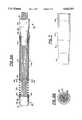
- FIG. 1is a perspective view of a fiber optic guide wire according to the present invention
- FIG. 2Ais an enlarged longitudinal cross-sectional view of a guide wire tip according to a first embodiment of the present invention
- FIG. 2Bis an enlarged axial cross-sectional view taken along the 2B--2B line of FIG. 2A;
- FIG. 3is a perspective view of an exchange mechanism of a guide wire according to the present invention.
- FIG. 4is an enlarged longitudinal cross-sectional view of the exchange mechanism of FIG. 3;
- FIG. 5is an enlarged longitudinal cross-sectional partial view of a guide wire section according to a second embodiment of the present invention.
- FIG. 6Ais an enlarged partial longitudinal cross-sectional view of the guide wire tip according to a second embodiment of the present invention.
- FIG. 6Bis an enlarged axial cross-sectional view taken along the 6B--6B line of FIG. 6A;
- FIG. 7is an enlarged longitudinal partial cross-sectional view of a guide wire according to a third embodiment of the present invention.
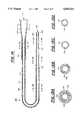
- FIG. 8is a longitudinal cross-sectional view of a guide wire according to a fourth embodiment of the present invention.
- FIGS. 9A and 9Bare perspective and cross-sectional views, respectively, of a torque knob according to the present invention.
- FIGS. 10A and 10Bare views of an insert used in the torque knob according to the present invention.
- FIGS. 11A-11Dare axial cross-sectional views of the guide wire of FIG. 8;
- FIG. 12is an enlarged longitudinal cross-sectional view of a distal portion of the guide wire of FIG. 8;
- FIGS. 13A and 13Bare perspective and cross-sectional views, respectively, of a guide wire according to the present invention used with a doc wire;
- FIG. 14is a longitudinal cross-sectional view of a support catheter according to the present invention.
- FIGS. 15A-15Dare axial cross-sectional views of the support catheter of FIG. 11.
- FIG. 1depicts a perspective view of a fiber optic guide wire 10 according to the present invention.
- a proximal end 12 of a light conveying cable 14is connected to a proximal mount 16 which can be coupled to a source of radiant energy. While any suitable coupling device may be used, the proximal mount described in U.S. patent application Ser. No. 07/899,470 to Nielson et al., now U.S. Pat. No. 5,321,783 (incorporated herein by reference) is preferred for this purpose.
- the light conveying cable 14is plastic tubing and has optical fibers disposed within, and these fibers are affixed to proximal mount 16 using techniques known in the art. A second end of light conveying cable 14 is attached to exchange mechanism 18, which will be described more fully herein.
- the distal side of exchange mechanism 18is connected to guide wire assembly 20.
- the distal end of guide wire assembly 20is terminated by tip 22, which will be described more fully herein.
- FIGS. 2A and 2Bare cross-sectional views of a first embodiment of the guide wire assembly 22 of FIG. 1.
- Guide wire assembly 22comprises optical fiber bundle 24 disposed within jacket 26.
- the bundlemay comprise, for example, 12-90 polyimide-buffered fibers each approximately 45-100 ⁇ m in diameter (of course, for larger fiber diameters, fewer fibers should be used), and the jacket may be made from any suitable material; for example, a polyester copolymer tubing such as Hytrel 82D has proven to be advantageous in this application.
- Jacket 26may additionally be coated with a suitable lubricant. An ultraviolet-curable hydrophilic coating manufactured by Bio-Metric Systems, Incorporated is advantageously employed for this purpose.
- the distal tip 22 of guide wire assembly 20comprises marker band 28.
- Marker band 28is advantageously made from a radiopaque material such as platinum-iridium and includes a proximal end 30 with a reduced outer diameter.
- the reduced outer diameter portion 30 of marker band 28is disposed between jacket 26 and optical fiber bundle 24 and is bonded with these components using a suitable adhesive such as Loctite 454 in a manner more fully described below.
- the distal rim of marker band 28may beveled at an angle ⁇ to give the catheter tip a less traumatic profile, thus enabling the tip to pass through vascular channels more easily.
- a bevel angle ⁇ of sixty degrees from the face of the marker bandhas been found to provide good results.
- the distal end of the optical fiber bundle 24may be potted within the marker band 28 using a glue plug, and the portion of the glue plug proximate to the marker band 28 may also be beveled at a sixty degree angle.
- the terminal face 36 of the optic fiber bundle 24may also be beveled to provide a smooth transitional area.
- the bevel angle of the fibersshould be no more than 23°.
- Longitudinal marker wire 32also runs within jacket 26. A distal end of longitudinal marker wire 32 is attached to a proximal end of marker band 28. Like marker band 28, longitudinal marker wire 32 is fabricated from a radiopaque material such as platinum so that the distal tip 22 of guide wire assembly 20 will be easily detectable by radioscopic diagnostic techniques. Additionally, longitudinal marker wire 32 adds stiffness to the hypo tube to jacket transition to aid in tracking the guide wire through tortuous vascular passages.
- hypo tube 34is bonded to the distal end of hypo tube 34.
- the proximal end of hypo tube 34is coupled to exchange mechanism 18
- Hypo tube 34is preferably constructed of stainless steel. Preferably, it is provided with a low-friction substance on its exterior surface such as Teflon® or a similar lubricant.
- Longitudinal marker wire 32extends through and is fixed to the proximal end of hypo tube 34.
- longitudinal marker wire 32increases the structural integrity of the guide wire by providing a strong connection between marker band 28 and the remainder of the guide wire should marker band 28 accidentally become disengaged from jacket 26 and optical fiber bundle 24.
- jacket 26is preferably approximately 8-12 cm in length, while hypo tube 34 preferably has a length of approximately 137 cm. Also, jacket 26 and hypo tube 34 preferably have an outer diameter of approximately 0.033 in. and an inner diameter of approximately 0.024 in.
- hypo tube 34As shown in FIG. 3, a proximal end of hypo tube 34 is attached to a distal side of exchange mechanism 18.
- Hypo tube 34 having optical fiber bundle 24 disposed thereinenters exchange mechanism 18 through cap 38 of a Tuohy-Borst connector.
- Light conveying cable 14enters exchange mechanism 18 through body 40 of the Tuohy-Borst connector and is coupled to hypo tube 34 as described below.
- Marking 88 on the exterior surface of light conveying cable 14indicates the proximal end of an exchange lead (not shown) as will be more fully described below.
- FIG. 4is a longitudinal cross-sectional view of exchange mechanism 18 which more clearly shows the coupling of hypo tube 34 to light conveying cable 14.
- Hypo tube 34enters exchange mechanism 18 through a hole 72 in Tuohy-Borst connector cap 38.
- the proximal end of hypo tube 34terminates within ring 74 (preferably a silicone ring), and the distal end of exchange lead 76 terminates within and is bonded to the proximal end of hypo tube 34.
- the proximal portion of exchange lead 76 exterior to ring 74is encased by tail tube 78 and extends approximately 100 cm on the proximal side of Tuohy-Borst body 40.
- Tail tube 78also serves as the exterior of light conveying cable 14.
- the distal end of tail tube 78is itself encased in two layers 80 and 82 of heat shrinkable material which serve as a strain relief for light conveying cable 14.
- Optical fiber bundle 24runs through the central lumen formed by the hypo tube-exchange
- Ring 74seats within Tuohy-Borst connector body 40 on a face 84 perpendicular to its longitudinal axis.
- Cap 38fits on the distal end of body 40 by way of screw threads, for example.
- Cap 38is fitted onto body 40 so that the proximal end of collar 86 of cap 38 presses against ring 74.
- ring 74is compressed along its longitudinal axis, thereby maintaining the position of exchange mechanism 18 along hypo tube 34.
- tail tube 78 and optical fiber bundle 24extend beyond the proximal end of exchange lead 76 and terminate in proximal mount 16. Connection of tail tube 78 and optical fiber bundle 24 may be accomplished using techniques disclosed in the above-referenced U.S. patent application Ser. No. 07/899,470 to Nielson et al.
- the point along tail tube 78 where exchange lead 76 terminatesmay be indicated with an appropriate marking 88 (FIG. 3). Marking 88 is useful when using guide wire 10 to position a catheter as described below.
- hypo tube 34must be prepared for assembly. Each end of a 0.033" outer diameter, 0.028" inner diameter, 138 cm length hypo tube is sanded flat. Then, each end is reamed to 0.028". Each end is then tapered by evenly sanding it at an angle. In this tapering process, the outer diameter of the tube should be reduced by approximately 0.0005" at the terminal face of the tube end. Then, the hypo tube should be rinsed and dried.
- jacket 26is prepared.
- a length of 0.027" ⁇ 0.033" Hytrel tubingis wiped with an isopropyl alcohol-soaked Kimwipe.
- the tubingis cut into 25 cm lengths and fitted on a 0.024" mandrel that has been deburred, cleaned and coated with Dow 360 silicone oil.
- a Teflon-coated mandrelmay be used; in this case, the silicone oil is not necessary.
- Approximately 5 cm of tubingshould extend beyond one end of the mandrel.
- the assemblyis then placed in a hot box set to provide a 2 psi air supply at 550° F.
- the portion of the tubing extending beyond the mandrelis tensioned with tweezers until it looses its elasticity. While maintaining tension on the tube, the assembly is then removed from the hot box and allowed to cool. After the tube is cooled, tension on the tube is released and the hytrel tubing is removed from the mandrel.
- the previously-tensioned portion of the tubeis cut at an angle to facilitate the insertion of 5 mm of the tubing or more into one end of the prepared hypo tube.
- the outer diameter of the necked portioni.e., the proximal end
- a razor bladeis used to make a perpendicular cut on the distal end of the tube to give the tube a total length of between 8.0 cm and 12.0 cm.
- longitudinal marker wire 32is prepared. A length of 0.003" diameter, 90% platinum--10% nickel wire is flattened. While taking care not to kink the flattened wire, it is cut into 155 cm lengths and set aside for later use.
- exchange lead 76is prepared.
- a cleaned, deburred 0.024" outer diameter ⁇ 1' length mandrelis wiped with a Kimwipe soaked in silicone oil.
- a Teflon-coated mandrelmay be used; in this case, the silicone oil is unnecessary.
- a 2' length of Hytrel tubingis cut into 15 cm lengths and an end of one of the cuttings is placed over the mandrel so that approximately 2" of the tube extends beyond the mandrel.
- a hot boxis then used to form the tubing to the mandrel in a process similar to that in the jacket fabrication described above.
- the mandrelWhen the assembly is removed from the hot box, the mandrel is partially pulled out of the tubing and the tubing is cut to provide a square tapered end of approximately 1 cm fitting on the mandrel. This process will form the proximal end of exchange lead 76.
- the distal end of exchange lead 76is prepared in a similar manner; however, as with jacket 26, the distal end of exchange lead 76 is cut at an angle to facilitate insertion into hypo tube 34. Once the distal end of exchange lead 76 has been prepared, the mandrel is removed and exchange lead 76 is wiped with an alcohol-soaked Kimwipe.
- tail tube 78 and the Tuohy-Borst connector assemblyare fabricated.
- a length of Raychem RNF 100 3/32" shrink tubingis cut into a 2 cm and a 2.5 cm length.
- Hytrel 82D tubinghaving an outer diameter of 0.058" and an inner diameter of 0.038" is cut to a length of 88 inches.
- ⁇ 0.036" ⁇ teflon coated mandrelis inserted into the tail tube.
- the 2.5 cm shrink tube 82is placed on one end of tail tube 78 and heat is applied to fix shrink tubing 82 on tail tube 78.
- the 2 cm shrink tube 80is similarly shrunk onto the 2.5 cm length 82.
- a 0.25" outer diameter, 0.052" inner diameter, 0.25" wide silicone ring 74is placed in Tuohy-Borst connector body 40 and cap 38 is then snapped and screwed onto body 40.
- a ring of EP30HT epoxyis deposited around the edge of shrink tube 80 and the end of the shrink tube/tail tube assembly is inserted into connector body 40 with a twisting motion to spread the epoxy along the interior surfaces of the connector body 40 contacting shrink tubing 80. The assembly is then allowed to cure.
- optical fiber bundle 24is formed. Twelve to ninety spools of 45-100 ⁇ m diameter optical fibers are loaded on a fiber pulling rack. Approximately four meters of fibers are pulled from the rack along a clean, planar surface. The fibers are then cut from the pulling rack using a cutting stone.
- optical fiber bundle 24is inserted into the proximal end of hypo tube 34. Approximately 20 cm of the fibers should extend beyond the distal end of hypo tube 34. This portion of the fibers is inserted into the proximal end of jacket 26 so that approximately 5 cm of the fibers extend beyond the distal end of jacket 26.
- Longitudinal marker wire 32is inserted into the distal end of jacket 26 until the proximal end of wire 32 appears at the proximal end of jacket 26 and then positioned so that approximately 1 cm of longitudinal marker wire 32 extends beyond the distal end of jacket 26. The marker wire is inserted into the hypo tube until it extends out of the proximal end of the hypo tube.
- jacket/marker wire assemblyis then moved toward hypo tube 34 so that the marker wire 32 and the proximal end of jacket 26 are inserted into hypo tube 34.
- Marker wire 32should be substantially parallel to the longitudinal axis of the hypo tube/jacket assembly with no twists.
- Jacket 26is then retracted from hypo tube 34 and its proximal end is coated with epoxy and reinserted into hypo tube 34. Excess epoxy is wiped away and the assembly is cured. The proximal end of longitudinal marker wire 32 extending beyond the proximal end of hypo tube 34 is trimmed to length.
- Exchange lead 76is then slid over the proximal end of optical fiber bundle 24 so that the proximal portion of longitudinal marker wire 32 is sandwiched between the exterior of the angled, tapered end of exchange lead 76 and the interior surface of hypo tube 34.
- Exchange lead 76is backed out of hypo tube 34, and exchange lead 76 and the end of hypo tube 34 are wiped with an alcohol-soaked Kimwipe.
- a ring of epoxyis deposited on the end of exchange lead 76 and it is reinserted into hypo tube 34. Excess epoxy is wiped away.
- the assemblyis then cured. Curing of the exchange lead/hypo tube bond may be performed concurrently with curing of the jacket/hypo tube bond to speed the fabrication process.
- the distal end of longitudinal marker wire 32is trimmed so it extends only 1 mm beyond the distal end of jacket 26, and the 1 mm end of the marker wire is fitted on the reduced diameter of the marker band 28.
- Reduced outer diameter portion 30is coated with cyanoacrylate adhesive and inserted into the lumen defined by jacket 26 so that it is sandwiched between the exterior of optical fiber bundle 24 and the interior surface of jacket 26. The assembly is cured, and excess adhesive is removed.
- optical fiber bundle 24may then be potted, beveled and polished using techniques known in the art. An advantageous method is described in U.S. Pat. No. 5,263,952 to Grace et al., incorporated herein by reference.
- the proximal end of fiber bundle 24is inserted into cap 38 of the Tuohy-Borst connector, the Tuohy-Borst assembly is moved distally and then tightened over the hypo tube/distal exchange section.
- the proximal ends of tail tube 78 and optical fiber bundle 24may be connected to proximal mount 16 as described in the above-referenced application 07/899,470 to Nielson et al.
- Guide wire 10may be advantageously used to ablate an intravascular occlusion and then to position a catheter for subsequent occlusion.
- guide wire 10is connected to a source of light energy such as a laser by way of proximal mount 16.
- Guide wire assembly 20is partially inserted into a patient using conventional surgical techniques and positioned so tip 22 is proximate to the occlusion. Energy transmitted from the source along optical fiber bundle 24 to tip 22 may then be used to ablate a channel through the occlusion.
- tip 22is positioned within the channel.
- Light conveying cable 14is severed where marking 88 indicates the termination of exchange lead 76.
- Tuohy-Borst cap 38is disengaged from body 40, and both pieces are slid off the proximal end with tail tube 78 and shrink tubes 80 and 82.
- the proximal end of newly-severed optical fiber bundle 24is pulled away from exchange lead 76 and then cut so that bundle 24 retracts inside exchange lead 76.
- a cathetermay be placed on the proximal end of exchange lead 76 and slid down to the entry point of hypo tube 34 in the patient's body.
- the catheteris then introduced into the patient's body and slid along hypo tube 34 until it is proximate to the partially-ablated occlusion.
- a laser cathetermay be used to ablate a larger area of the occlusion.
- a balloon cathetermay be used to dilate the vascular area having the occlusion instead of a laser catheter.
- FIG. 5is a partial longitudinal cross-sectional view of a second embodiment of the guide wire assembly 10 of FIG. 1. From hypo tube 34 in the proximal direction, this embodiment is the same as that described relative to FIGS. 3 and 4. However, this embodiment differs from the previous embodiment distal to hypo tube 34. In FIG. 5, optical fiber bundle 24 has been removed to more clearly show the internal structure of guide wire assembly 20. Instead of using a polymer jacket on the distal end of hypo tube 34, this embodiment employs helical, radiopaque coil 68 to form the distal end of guide wire assembly 20. Hypo tube 34 includes an intermediate tapered portion 42 connected to a reduced diameter portion 44 on its distal end.
- Hypo tube 34is preferably constructed from stainless steel and, proximal to tapered portion 42, has an outer diameter of approximately 0.018 in. and an inner diameter of approximately 0.013 in. Also, hypo tube 34 may be coated to provide a low-friction surface for improved guide wire maneuverability characteristics. A suitable coating for this purpose is Teflon®.
- Coil 68has a proximal end covering and connected to the reduced diameter portion 44 of hypo tube 34 and a distal end which is fixed to marker band 28.
- Coil 68is preferably fabricated from a radiopaque material such as platinum so the guide wire may be tracked using radioscopic techniques as described above.
- Coil 68has a proximal compressed portion 52 and a distal expanded portion 54. By stretching distal expanded portion 54 of coil 68, the distal end of guide wire assembly 22 can better track vascular contours while compressed portion 52 provides rigidity to the structure.
- a coil fabricated from a 90% platinum--10% nickel alloy having a wire diameter of 0.0025 in.is suitable for this purpose and additionally provides desirable flexibility, torquability and pushability characteristics.
- expanded portion 54 of coil 68is approximately 3 cm in length, while compressed portion 52 of coil 68 is approximately 27 cm in length.
- marker band 28is preferably fabricated from a 90% platinum--10% iridium alloy and has an outer diameter of approximately 0.018 in., an inner diameter of approximately 0.013 in., and a length of approximately 2 mm.
- Mandrel 70is mounted on an inner surface of reduced diameter portion 44 of hypo tube 34 and provides additional rigidity, torquability and pushability to guide wire assembly 20.
- Mandrel 70has a proximal portion 46 eccentrically bonded to hypo tube 34 and an intermediate portion 48 which tapers down to a flattened portion 50 at its distal end.
- Mandrel 70is angled so that the distal end of flattened portion 50 is substantially central to and coterminal with terminal face 36.
- mandrel 70is fabricated from stainless steel, with the proximal portion 46 thereof having a diameter of approximately 0.005 in. and a length of approximately 15 cm, the intermediate tapered portion 48 thereof having a length of approximately 10 cm, and the flattened portion 50 thereof having a width of approximately 0.006 in., a thickness of approximately 0.002 in. and a length of approximately 3 cm.
- FIGS. 6A and 6Bare cross-sectional views of the second embodiment of the invention showing the placement of optical fiber bundle 24.
- Optical fiber bundle 24emerges from reduced diameter portion 44 of hypo tube 34 and extends to terminate at the distal end of a glue plug 62 in marker band 28.
- optical fiber bundle 24is preferably comprised of a bundle of approximately 9-33 polyimide-buffered optical fibers each having a diameter of about 30-61 (most preferably, 45) ⁇ m.
- the proximal end of coil 68is attached to hypo tube 34 by solder joint 56.
- a joint 60is used to attach the distal end of coil 68 to marker band 28.
- the joint 60may be a solder joint, an adhesive joint, a fused joint combining adhesive and heat, or the like.
- the joint 60is an adhesive or fused joint.
- a central joint 58(preferably an adhesive or fused joint, although other joints, such as a solder joint can be employed) bonds the interface between compressed portion 52 and expanded portion 54 of coil 68 to mandrel 70. While the first two of the above-mentioned joints are annular in shape, central joint 58 is essentially disk-shaped, since the molten solder tends to flow between cracks in the coil turns and wick throughout the optical fiber bundle 24 in that region.
- coil 68is formed and its distal portion is stretched approximately 50% to form expanded portion 54, while the remainder of coil 68 forms compressed portion 52.
- Proximal portion 46 of mandrel 70is bonded to reduced diameter portion 44 of hypo tube 34.
- the proximal end of coil 68is fitted over the reduced diameter portion 44 and soldered thereto.
- Marker band 28is soldered to the distal end of coil 68.
- Optical fiber bundle 24is inserted into the jacket/hypo tube assembly so that its distal end protrudes from marker band 28.
- Coil interface solder joint 58is then formed by flowing solder at the transition between the compressed portion 52 and the expanded portion 54 of coil 68 and into optical fiber bundle 24 to bond with mandrel 70. Finally, a suitable adhesive is wicked up the distal end of optical fiber bundle 24 to form glue plug 62 within marker band 28 and terminal face 36 is polished to provide an optically smooth surface. Also, the periphery of terminal face 36 may be bevelled as described above.
- the remainder of the devicemay be constructed in a manner similar to the one previously described in the construction of the first embodiment of the present invention.
- hypo tube 34 and coil 68are together preferably approximately 175 cm long.
- hypo tube 34 in this embodimentis longer than that of the first embodiment, which is preferably used in peripheral angioplasty applications. Since both techniques generally introduce the guide wire into the patient's body at the groin area, additional length is required in the coronary version to reach the more distantly located vessels near the heart.
- FIG. 7depicts a portion of a third embodiment of the present invention.
- hypo tube 134is shortened to provide a small fitting for connecting coil 68 to jacket 64, which substantially replaces hypo tube 34 in the second embodiment. Construction of this embodiment is similar to that of the second embodiment; however, the proximal end of hypo tube 134 is attached to jacket 64 with a suitable adhesive such as cyanoacrylate.
- the second and third embodiments of the present inventioncan be used in a manner similar to that described above for the first embodiment.
- FIG. 8is a partial longitudinal cross-sectional view of a fourth embodiment of the guide wire assembly 10 of FIG. 1, and a detailed cross-sectional view of the distal end of this embodiment is shown in FIG. 12. From exchange lead 76 in the proximal direction, this embodiment is the same as that described relative to the first, second and third embodiments; however, the distal portion differs from those aforementioned embodiments.
- optical fiber bundle 224has been removed to more clearly show the internal structure of guide wire assembly 20.
- Optical fiber bundle 224is more clearly shown in FIGS. 11A-11D.
- This embodimentemploys a helical, radiopaque coil 268 to form the distal end of guide wire assembly 20.
- a distal jacket 90 having a tapered distal portion 92 fitting within the proximal end of the coil 268extends from the distal end of a cylindrical hypo tube 234 to the proximal end of the coil 268.
- the distal jacket 90is bonded to the hypo tube 234 by a fused adhesive bond 94 and to the coil 268 by an adhesive bond 256.
- the proximal end of the hypo tube 234is connected to the distal end of the exchange lead 76 with another adhesive heat bond 96.
- the distal jacket 90is preferably constructed from a 27 centimeter length of material such as high density polyethylene (HDPE) and is approximately 0.018" OD and 0.013" ID.
- Coil 268is approximately 3 centimeters long with an 0.018" OD and is preferably fabricated from a radiopaque material such as a 90% platinum--10% nickel alloy having a wire diameter of 0.0025 in. so the guide wire may be tracked using radioscopic techniques as described above.
- Hypo tube 234is preferably constructed from a 145 centimeter length of stainless steel and has an outer diameter of approximately 0.018 in. and an inner diameter of approximately 0.013 in.
- the coil 268 and the distal jacket 90may be coated with a lubricous hydrophilic coating.
- hypo tube 234may be coated with Teflon® to reduce friction.
- Mandrel 270is fixed in place relative to the coil 268, distal jacket 90, hypo tube 234 and exchange lead 76 and provides additional rigidity, torquability and pushability to guide wire assembly 20.
- Mandrel 270has a proximal portion 246 extending from the proximal end of exchange lead 76 and an intermediate portion 248 having tapered portions at each end so that the intermediate portion 248 enhances the stiffness profile and trackability characteristics of the distal end of the guide wire assembly 20.
- a flattened distal portion 250 of mandrel 270extends to a distal face 236 of the guide wire assembly 20 and is bonded to a distal end of the coil 268 with an epoxy glue plug 262.
- mandrel 270is fabricated from stainless steel, with the proximal portion 246 thereof having a diameter of approximately 0.005 or 0.006 in., the intermediate tapered portion 248 thereof having a diameter of about 0.008 in. and the flattened portion 250 thereof having a width of approximately 0.006 in., a thickness of approximately 0.0025 in. and a length of approximately 3 cm.
- the flattened portion 250has a rectangular cross-section and cooperates with the optical fibers to allow the guide wire assembly 20 to be shaped and reshaped to bend it at almost any desired angle.
- the Tuohy-Borst connector used in previous embodimentshas been eliminated, and a torque knob 272 has been used in its place.
- the torque knob 272is advantageous because it can be used to torque the guide wire assembly 20, and the Tuohy-Borst connector could not.
- the torque knob 272does not secure the tail tube 78 to the hypo tube 234, and the torque knob 272 can be positioned at almost any location along the shaft of the hypo tube 234 for ease of handling, torquing and steering during a procedure.
- FIGS. 9A and 9Bshow the torque knob 272 in greater detail.
- the exterior of the torque knob 272is shown the perspective view of FIG. 9A, and a cross-sectional view is shown in FIG. 9B.
- cap 274 of torque knob 272is tightened onto the body 276, the insert 278 shown in detail in FIGS. 10A and 10B is compressed and sections 280 of its distal end close around and engage hypo tube 234. Torque knob 272 then may be rotated to apply torque to the guide wire assembly 20.
- FIGS. 11A-11Dare cross-sectional views of the second embodiment of the invention showing the placement of optical fiber bundle 224.
- Optical fiber bundle 224passes through the exchange lead 76, the hypo tube 234, the distal jacket 90, and the coil 268 and terminates at the distal face 236 of the guide wire assembly in a glue plug 262.
- the marker band used in the previously-mentioned embodimentsmay be eliminated, thus reducing the cost of making the guide wire assembly 20.
- the edge of the distal end 236 of the guide wire assembly 22can beveled to provide a less traumatic profile for the invention.
- the optical fiber bundle 224may have a short (approximately 1 cm) length of shrink tube 98 encircling it between the proximal end of the exchange lead 76 and the marking 88.
- the shrink tube 98retains the discarded portion of the optical fiber bundle 224 together as will be described in more detail below.
- optical fiber bundle 224is preferably comprised of a bundle of approximately 9-33 polyimide-buffered optical fibers each having a diameter of 30-61 (most preferably 45) ⁇ m.
- the arrangement of the distal coil and jacket assembly in this embodimentis particularly advantageous in maneuvering the guide wire 20. If the coil 268 on the jacket 90 is constricted within an artery or lesion, torque still may be transmitted from the torque knob 272 to the distal face 236 of the guide wire 20. This is because the coil and jacket combination is secured to the rest of the assembly only at the extreme distal face 236 and at its proximal end by adhesive bond 256, and the fibers and mandrel 270 are fairly loosely packed within the coil 268. When torque is applied to the guide wire 20 by the torque knob 272, it can be conveyed to the distal tip 236 via the mandrel without binding the coil and jacket combination.
- This embodimentmay of course be used clinically in a manner substantially similar to the previous embodiments.
- torque knob 272is not connected to tail tube 78 as is the Tuohy-Borst connector of the previous embodiments, removing torque knob 272 helps remove tail tube 78.
- the exchange lead 76may be constructed from a braided polymer material with a waffle-like surface instead of a relatively homogenous polymer material. A substantial portion of the exchange lead 76 may even be replaced by an equal or reduced diameter portion of the hypo tube.
- FIG. 13Ashows a distal portion of the doc wire 282 engaging the proximal end of the hypo tube 234.
- the doc wire 282is coupled to the hypo tube 234 by a crimp 284.
- the doc wire 282is made of stainless steel or nickel-titanium and has a low friction coating such as Teflon® or Parylene® covering it.
- the doc wire 282has an outer diameter the same as or slightly smaller than the outer diameter of the hypo tube 234.
- a guide wire according to the fourth embodiment of the present inventionis particularly well-suited to applications such as coronary angioplasty.
- distal jacket 90 and coil 268are together preferably approximately 30 centimeters long.
- the working length (the hypotube, jacket and coil) of the guide wire 20is then 175 cm, and the exchange section covered by the tail tubing is 125 cm, for a total length of 300 cm.
- FIG. 14is a longitudinal cross-sectional view of the support catheter according to the present invention
- FIGS. 15A-15Dare axial cross-sectional views along the support catheter.
- the support catheterhas a proximal end 310 terminating in a female luer connector 312.
- a catheter body 316extends from the distal portion of the luer connector 312 to a distal catheter end 324 and in conjunction with the luer connector 312 defines a lumen 318 therewithin.
- a proximal jacket 320covers the proximal portion of the catheter body 316, and a luer leg 314 of the luer connector 312 covers the proximal end of the proximal jacket 320.
- the luer connector 312, the proximal jacket 320 and the catheter body 316are made from HDPE.
- the luer connector 312is about 10 centimeters long with a 5 centimeter overlap with the proximal jacket 320 and the catheter body 316, and the luer leg has about a 0.080" OD and a 0.050" ID.
- the proximal jacketis approximately 100 centimeters long with a 0.039" OD and a 0.045" ID
- the catheter body 316preferably is approximately 130 centimeters long with a tapered portion 322 thereof being about 10 centimeters from its distal face 324 and transitioning from a proximal portion of 0.036" OD and 0.025" ID to a distal portion of 0.031" OD and 0.022" ID.
- the support catheterexhibits a stiffness profile that progressively decreases from the proximal end to the distal end thereof.
- the catheter body 316has a tapered portion 322 intermediate the distal end 330 of the proximal jacket 320 and the distal end 324 of the catheter.
- This portion 330preferably is tapered to impart a less traumatic profile to the support catheter when used in situ.
- the distal end 330 of the proximal jacket 320 and the rim of the distal end 324 of the cathetermay be tapered for similar reasons.
- its distal 30 centimetersmay be covered with a lubricous hydrophilic coating.
- a radiopaque band 328is disposed near the distal end 324 of the catheter to aid in fluoroscope visualization of the placement of distal end 324.
- the band 328is about 1 millimeter wide with a 0.031" OD and a 0.027" ID.
- the guide wire 20is inserted into the support catheter lumen 318 and advanced until catheter distal face 324 and the guide wire distal face are coterminal.
- the support catheter-guide wire assemblyis then introduced into the patient's body using a guide catheter as is known in the art. After the catheter-guide wire assembly has passed beyond the distal end of the guide catheter, the guide wire 20 is advanced out of the support catheter to a treatment site. Once positioned, the support catheter 300 also may be advanced to the treatment site to provide additional support. During this process, the support catheter 300 may be hydrated or irrigated with saline solution through its lumen 318 before insertion of the guide wire 20 to reduce friction.
- the guide wire 20is used to ablate part of the obstruction to create a passage.
- the distal end of the guide wire 20is then positioned beyond the obstruction.
- the torque knob 272is loosened and removed.
- the guide wire 20is severed to disconnect the proximal mount portion from the portion disposed in the patient's body. After this is done, removal of the torque knob 272 also aids in removal of the tail tube 78.
- the proximal end of the exchange lead 76will have a short length of optical fiber bundle 224 projecting therefrom and encircled by shrink tube 98.
- Tensionis applied to the optical fiber bundle 224 to withdraw it from the exchange lead 76 a little more, and it is severed at the end of the exchange lead 76. With the tension released, the end of optical fiber bundle 224 retracts inside the exchange lead 76, thereby leaving a clean termination. Since fibers in the excess length of the optical fiber bundle 224 are held together by shrink tube 98, they are prevented from falling onto the patient or other undesirable places.
- the support catheter 300then is slid off the guide wire 20, and a conventional balloon or optical fiber catheter is slid on to further treat the site.
- the treatment cathetermay be off-loaded and freely swapped with a number of other treatment catheters for additional treatment operations.
- the guide wire 20may be removed and replaced by a differently-sized conventional guide wire.
- a conventional treatment cathetermay be used in place of the support catheter.
- the support catheter 300is suitable for other applications in intravascular angioplasty.
- the support cathetermay be used as a conduit for exchanging guide wires or for maintaining position at a treatment site while a guide wire is withdrawn. That is, if a doctor wishes to reshape a guide wire currently in place, she can withdraw the guide wire through the support catheter while maintaining position with the support catheter. Once the guide wire is reshaped, it can be advanced inside the support catheter to the treatment site as described above.
- the support catheter 300may be moved over a guide wire, the position of the guide wire tip may be altered. Further, the support catheter may be used as a conduit for injecting therapeutic or diagnostic fluids. Also, the catheter may be used to cross lesions.
Landscapes
- Health & Medical Sciences (AREA)
- Life Sciences & Earth Sciences (AREA)
- Physics & Mathematics (AREA)
- Public Health (AREA)
- Engineering & Computer Science (AREA)
- Surgery (AREA)
- Biomedical Technology (AREA)
- Heart & Thoracic Surgery (AREA)
- Veterinary Medicine (AREA)
- Animal Behavior & Ethology (AREA)
- General Health & Medical Sciences (AREA)
- Molecular Biology (AREA)
- Medical Informatics (AREA)
- Vascular Medicine (AREA)
- Pulmonology (AREA)
- Optics & Photonics (AREA)
- Electromagnetism (AREA)
- Nuclear Medicine, Radiotherapy & Molecular Imaging (AREA)
- Otolaryngology (AREA)
- Anesthesiology (AREA)
- Hematology (AREA)
- Biophysics (AREA)
- Media Introduction/Drainage Providing Device (AREA)
- Laser Surgery Devices (AREA)
- Application Of Or Painting With Fluid Materials (AREA)
- Materials For Medical Uses (AREA)
- Radiation-Therapy Devices (AREA)
- Ropes Or Cables (AREA)
- Light Guides In General And Applications Therefor (AREA)
- Cell Electrode Carriers And Collectors (AREA)
Abstract
Description
Claims (11)
Priority Applications (1)
| Application Number | Priority Date | Filing Date | Title |
|---|---|---|---|
| US08/539,079US5643251A (en) | 1992-08-18 | 1995-10-04 | Fibert optic guide wire and support catheter therefor |
Applications Claiming Priority (3)
| Application Number | Priority Date | Filing Date | Title |
|---|---|---|---|
| US93093492A | 1992-08-18 | 1992-08-18 | |
| US08/225,061US5514128A (en) | 1992-08-18 | 1994-04-08 | Fiber optic guide wire and support catheter therefor |
| US08/539,079US5643251A (en) | 1992-08-18 | 1995-10-04 | Fibert optic guide wire and support catheter therefor |
Related Parent Applications (1)
| Application Number | Title | Priority Date | Filing Date |
|---|---|---|---|
| US08/225,061DivisionUS5514128A (en) | 1992-08-18 | 1994-04-08 | Fiber optic guide wire and support catheter therefor |
Publications (1)
| Publication Number | Publication Date |
|---|---|
| US5643251Atrue US5643251A (en) | 1997-07-01 |
Family
ID=25459984
Family Applications (2)
| Application Number | Title | Priority Date | Filing Date |
|---|---|---|---|
| US08/225,061Expired - LifetimeUS5514128A (en) | 1992-08-18 | 1994-04-08 | Fiber optic guide wire and support catheter therefor |
| US08/539,079Expired - LifetimeUS5643251A (en) | 1992-08-18 | 1995-10-04 | Fibert optic guide wire and support catheter therefor |
Family Applications Before (1)
| Application Number | Title | Priority Date | Filing Date |
|---|---|---|---|
| US08/225,061Expired - LifetimeUS5514128A (en) | 1992-08-18 | 1994-04-08 | Fiber optic guide wire and support catheter therefor |
Country Status (6)
| Country | Link |
|---|---|
| US (2) | US5514128A (en) |
| EP (1) | EP0597195B1 (en) |
| JP (1) | JP3623523B2 (en) |
| AT (1) | ATE182273T1 (en) |
| CA (1) | CA2104239A1 (en) |
| DE (1) | DE69325692T2 (en) |
Cited By (137)
| Publication number | Priority date | Publication date | Assignee | Title |
|---|---|---|---|---|
| WO1999009919A1 (en) | 1997-08-27 | 1999-03-04 | Arthrocare Corporation | Electrosurgical systems and methods for the removal of pacemaker leads |
| US6083167A (en)* | 1998-02-10 | 2000-07-04 | Emory University | Systems and methods for providing radiation therapy and catheter guides |
| US6165140A (en) | 1998-12-28 | 2000-12-26 | Micrus Corporation | Composite guidewire |
| US6179824B1 (en) | 1993-05-10 | 2001-01-30 | Arthrocare Corporation | System and methods for electrosurgical restenosis of body lumens |
| EP1075820A1 (en)* | 1999-08-10 | 2001-02-14 | Biosense Webster, Inc. | Atrial ablation catheter |
| US6240231B1 (en) | 1997-12-22 | 2001-05-29 | Micrus Corporation | Variable stiffness fiber optic shaft |
| US6308092B1 (en)* | 1999-10-13 | 2001-10-23 | C. R. Bard Inc. | Optical fiber tissue localization device |
| US6352531B1 (en) | 1999-03-24 | 2002-03-05 | Micrus Corporation | Variable stiffness optical fiber shaft |
| US6582423B1 (en) | 1997-06-13 | 2003-06-24 | Arthrocare Corporation | Electrosurgical systems and methods for recanalization of occluded body lumens |
| US6680439B2 (en)* | 2001-05-22 | 2004-01-20 | Sediver Societe Europeenne D'isolateurs Er. Verre Et Composite | Composite electrical insulator having an outer coating and at least one optical fiber compatible therewith |
| US20040034311A1 (en)* | 2000-05-19 | 2004-02-19 | Albert Mihalcik | Guidewire with viewing capability |
| US20040195132A1 (en)* | 2001-06-13 | 2004-10-07 | Jane Sheetz | Fiberoptic coil tray and carrier package |
| US6855143B2 (en) | 1997-06-13 | 2005-02-15 | Arthrocare Corporation | Electrosurgical systems and methods for recanalization of occluded body lumens |
| US6887235B2 (en) | 1999-03-24 | 2005-05-03 | Micrus Corporation | Variable stiffness heating catheter |
| US20050096642A1 (en)* | 2003-10-31 | 2005-05-05 | Appling William M. | Endovascular treatment apparatus and method |
| US20050119651A1 (en)* | 2002-07-19 | 2005-06-02 | Biosense Webster, Inc. | Atrial ablation catheter and method for treating atrial fibrillation |
| US6915806B2 (en) | 1993-05-10 | 2005-07-12 | Arthrocare Corporation | Method for harvesting graft vessel |
| US20060036164A1 (en)* | 2001-06-19 | 2006-02-16 | The Trustees Of The University Of Pennsylvania | Optically guided system for precise placement of a medical catheter in a patient |
| US20060142747A1 (en)* | 2002-12-11 | 2006-06-29 | Appling William M | Method of thermally treating blood vessels |
| US7273056B2 (en) | 2001-06-19 | 2007-09-25 | The Trustees Of The University Of Pennsylvania | Optical guidance system for invasive catheter placement |
| US20080004647A1 (en)* | 2006-06-30 | 2008-01-03 | Atheromed, Inc. | Atherectomy devices and methods |
| US20080004646A1 (en)* | 2006-06-30 | 2008-01-03 | Atheromed, Inc. | Atherectomy devices and methods |
| US20080004644A1 (en)* | 2006-06-30 | 2008-01-03 | Atheromed, Inc. | Atherectomy devices and methods |
| US20080015558A1 (en)* | 2006-04-04 | 2008-01-17 | The Spectranetics Corporation | Laser-assisted guidewire having a variable stiffness shaft |
| US20080039715A1 (en)* | 2004-11-04 | 2008-02-14 | Wilson David F | Three-dimensional optical guidance for catheter placement |
| EP1894511A1 (en)* | 2006-08-30 | 2008-03-05 | Karl Storz GmbH & Co. KG | Stroboscope module with a coupler |
| US20080058789A1 (en)* | 2006-09-06 | 2008-03-06 | Cardiofirst | Guidance system used in treating chronic occlusion |
| US20080077225A1 (en)* | 2006-09-22 | 2008-03-27 | Carlin Donald B | Accuracy lumen sizing and stent expansion |
| US20080154345A1 (en)* | 2006-12-26 | 2008-06-26 | Spectranetics | Multi-Port Light Delivery Catheter And Methods For The Use Thereof |
| US20080194973A1 (en)* | 2005-09-13 | 2008-08-14 | Imam Farhad B | Light-guided transluminal catheter |
| US20080208180A1 (en)* | 2002-07-10 | 2008-08-28 | Cartier William A | Endovascular treatment sheath having a heat insulative tip and method for using the same |
| US7422585B1 (en) | 1992-01-07 | 2008-09-09 | Arthrocare Corporation | System for electrosurgical myocardial revascularization |
| US20080249515A1 (en)* | 2006-01-27 | 2008-10-09 | The Spectranetics Corporation | Interventional Devices and Methods For Laser Ablation |
| US20090018565A1 (en)* | 2006-06-30 | 2009-01-15 | Artheromed, Inc. | Atherectomy devices, systems, and methods |
| US20090198221A1 (en)* | 2004-09-17 | 2009-08-06 | The Spectranetics Corporation | Apparatus and methods for directional delivery of laser energy |
| US20090234378A1 (en)* | 2007-10-22 | 2009-09-17 | Atheromed, Inc. | Atherectomy devices and methods |
| US20090254074A1 (en)* | 2008-04-02 | 2009-10-08 | Spectranetics | Liquid light-guide catheter with optically diverging tip |
| CN101563019A (en)* | 2006-09-15 | 2009-10-21 | 阿克莱特公司 | Methods and devices for facilitating visualization in a surgical environment |
| US20090263729A1 (en)* | 2008-04-21 | 2009-10-22 | Micron Technology, Inc. | Templates for imprint lithography and methods of fabricating and using such templates |
| US20090306637A1 (en)* | 2008-06-04 | 2009-12-10 | Vnus Medical Technologies, Inc. | Energy devices and methods for treating hollow anatomical structures |
| US20100016842A1 (en)* | 2008-07-21 | 2010-01-21 | Spectranetics | Tapered Liquid Light Guide |
| US20100152720A1 (en)* | 2008-12-12 | 2010-06-17 | Spectranetics | Offset catheter |
| US20100152717A1 (en)* | 2008-12-17 | 2010-06-17 | Spectranetics | Eccentric balloon laser catheter |
| US20100285167A1 (en)* | 2005-06-17 | 2010-11-11 | Micron Technology, Inc. | Templates for use in imprint lithography and related intermediate template structures |
| US20110009750A1 (en)* | 2004-09-17 | 2011-01-13 | Spectranetics | Cardiovascular imaging system |
| US20110137385A1 (en)* | 2007-05-10 | 2011-06-09 | Tamara Colette Baynham | Method and apparatus for relieving angina symptoms using light |
| US8078261B2 (en) | 2005-09-13 | 2011-12-13 | Children's Medical Center Corporation | Light-guided transluminal catheter |
| US8080000B2 (en) | 2004-04-21 | 2011-12-20 | Acclarent, Inc. | Methods and apparatus for treating disorders of the ear nose and throat |
| US8088101B2 (en) | 2004-04-21 | 2012-01-03 | Acclarent, Inc. | Devices, systems and methods for treating disorders of the ear, nose and throat |
| US8100933B2 (en) | 2002-09-30 | 2012-01-24 | Acclarent, Inc. | Method for treating obstructed paranasal frontal sinuses |
| US8114062B2 (en) | 2004-04-21 | 2012-02-14 | Acclarent, Inc. | Devices and methods for delivering therapeutic substances for the treatment of sinusitis and other disorders |
| US8114113B2 (en) | 2005-09-23 | 2012-02-14 | Acclarent, Inc. | Multi-conduit balloon catheter |
| US8118757B2 (en) | 2007-04-30 | 2012-02-21 | Acclarent, Inc. | Methods and devices for ostium measurement |
| US8142422B2 (en) | 2004-04-21 | 2012-03-27 | Acclarent, Inc. | Devices, systems and methods for diagnosing and treating sinusitis and other disorders of the ears, nose and/or throat |
| US8146400B2 (en) | 2004-04-21 | 2012-04-03 | Acclarent, Inc. | Endoscopic methods and devices for transnasal procedures |
| US8172828B2 (en) | 2004-04-21 | 2012-05-08 | Acclarent, Inc. | Apparatus and methods for dilating and modifying ostia of paranasal sinuses and other intranasal or paranasal structures |
| US8182432B2 (en) | 2008-03-10 | 2012-05-22 | Acclarent, Inc. | Corewire design and construction for medical devices |
| US8190389B2 (en) | 2006-05-17 | 2012-05-29 | Acclarent, Inc. | Adapter for attaching electromagnetic image guidance components to a medical device |
| WO2012075479A3 (en)* | 2010-12-03 | 2012-08-02 | Shifamed Holdings, Llc | Systems and methods for deep vascular access |
| US8236016B2 (en) | 2007-10-22 | 2012-08-07 | Atheromed, Inc. | Atherectomy devices and methods |
| US8291915B2 (en) | 1997-03-04 | 2012-10-23 | Tyco Healthcare Group Lp | Method and apparatus for treating venous insufficiency using directionally applied energy |
| US8388642B2 (en) | 2005-01-18 | 2013-03-05 | Acclarent, Inc. | Implantable devices and methods for treating sinusitis and other disorders |
| US8414473B2 (en) | 2004-04-21 | 2013-04-09 | Acclarent, Inc. | Methods and apparatus for treating disorders of the ear nose and throat |
| US8435290B2 (en) | 2009-03-31 | 2013-05-07 | Acclarent, Inc. | System and method for treatment of non-ventilating middle ear by providing a gas pathway through the nasopharynx |
| US8435235B2 (en) | 2007-04-27 | 2013-05-07 | Covidien Lp | Systems and methods for treating hollow anatomical structures |
| US8439687B1 (en) | 2006-12-29 | 2013-05-14 | Acclarent, Inc. | Apparatus and method for simulated insertion and positioning of guidewares and other interventional devices |
| US20130137920A1 (en)* | 2011-11-25 | 2013-05-30 | Cook Medical Technologies Llc | Steerable Guide Member and Catheter |
| US8485199B2 (en) | 2007-05-08 | 2013-07-16 | Acclarent, Inc. | Methods and devices for protecting nasal turbinate during surgery |
| US8628519B2 (en) | 2004-09-17 | 2014-01-14 | The Spectranetics Corporation | Rapid exchange bias laser catheter design |
| US8702626B1 (en) | 2004-04-21 | 2014-04-22 | Acclarent, Inc. | Guidewires for performing image guided procedures |
| US8715169B2 (en) | 2004-04-21 | 2014-05-06 | Acclarent, Inc. | Devices, systems and methods useable for treating sinusitis |
| US8740929B2 (en) | 2001-02-06 | 2014-06-03 | Acclarent, Inc. | Spacing device for releasing active substances in the paranasal sinus |
| US8747389B2 (en) | 2004-04-21 | 2014-06-10 | Acclarent, Inc. | Systems for treating disorders of the ear, nose and throat |
| US8764729B2 (en) | 2004-04-21 | 2014-07-01 | Acclarent, Inc. | Frontal sinus spacer |
| US8795306B2 (en) | 2011-10-13 | 2014-08-05 | Atheromed, Inc. | Atherectomy apparatus, systems and methods |
| US20140277003A1 (en)* | 2013-03-13 | 2014-09-18 | The Spectranetics Corporation | Material Capturing Guidewire |
| US8864787B2 (en) | 2004-04-21 | 2014-10-21 | Acclarent, Inc. | Ethmoidotomy system and implantable spacer devices having therapeutic substance delivery capability for treatment of paranasal sinusitis |
| US8894614B2 (en) | 2004-04-21 | 2014-11-25 | Acclarent, Inc. | Devices, systems and methods useable for treating frontal sinusitis |
| US8932276B1 (en) | 2004-04-21 | 2015-01-13 | Acclarent, Inc. | Shapeable guide catheters and related methods |
| US8951225B2 (en) | 2005-06-10 | 2015-02-10 | Acclarent, Inc. | Catheters with non-removable guide members useable for treatment of sinusitis |
| US8979888B2 (en) | 2008-07-30 | 2015-03-17 | Acclarent, Inc. | Paranasal ostium finder devices and methods |
| US9039680B2 (en) | 2004-08-04 | 2015-05-26 | Acclarent, Inc. | Implantable devices and methods for delivering drugs and other substances to treat sinusitis and other disorders |
| US9072626B2 (en) | 2009-03-31 | 2015-07-07 | Acclarent, Inc. | System and method for treatment of non-ventilating middle ear by providing a gas pathway through the nasopharynx |
| US9089258B2 (en) | 2004-04-21 | 2015-07-28 | Acclarent, Inc. | Endoscopic methods and devices for transnasal procedures |
| US9101384B2 (en) | 2004-04-21 | 2015-08-11 | Acclarent, Inc. | Devices, systems and methods for diagnosing and treating sinusitis and other disorders of the ears, Nose and/or throat |
| US9155492B2 (en) | 2010-09-24 | 2015-10-13 | Acclarent, Inc. | Sinus illumination lightwire device |
| US9265407B2 (en) | 2004-04-21 | 2016-02-23 | Acclarent, Inc. | Endoscopic methods and devices for transnasal procedures |
| US9289173B2 (en) | 2007-11-09 | 2016-03-22 | The Spectranetics Corporation | Intra-vascular device with pressure detection capabilities using pressure sensitive material |
| US9308016B2 (en) | 2006-06-30 | 2016-04-12 | Atheromed, Inc. | Devices, systems, and methods for performing atherectomy including delivery of a bioactive material |
| US9314263B2 (en) | 2006-06-30 | 2016-04-19 | Atheromed, Inc. | Atherectomy devices, systems, and methods |
| US9351750B2 (en) | 2004-04-21 | 2016-05-31 | Acclarent, Inc. | Devices and methods for treating maxillary sinus disease |
| US9399121B2 (en) | 2004-04-21 | 2016-07-26 | Acclarent, Inc. | Systems and methods for transnasal dilation of passageways in the ear, nose or throat |
| US9433437B2 (en) | 2013-03-15 | 2016-09-06 | Acclarent, Inc. | Apparatus and method for treatment of ethmoid sinusitis |
| US9468362B2 (en) | 2004-04-21 | 2016-10-18 | Acclarent, Inc. | Endoscopic methods and devices for transnasal procedures |
| US9492192B2 (en) | 2006-06-30 | 2016-11-15 | Atheromed, Inc. | Atherectomy devices, systems, and methods |
| US9526426B1 (en) | 2012-07-18 | 2016-12-27 | Bernard Boon Chye Lim | Apparatus and method for assessing tissue composition |
| USD775728S1 (en) | 2015-07-02 | 2017-01-03 | The Spectranetics Corporation | Medical device handle |
| US9623211B2 (en) | 2013-03-13 | 2017-04-18 | The Spectranetics Corporation | Catheter movement control |
| US9629684B2 (en) | 2013-03-15 | 2017-04-25 | Acclarent, Inc. | Apparatus and method for treatment of ethmoid sinusitis |
| US9675376B2 (en) | 2006-06-30 | 2017-06-13 | Atheromed, Inc. | Atherectomy devices and methods |
| US9757200B2 (en) | 2013-03-14 | 2017-09-12 | The Spectranetics Corporation | Intelligent catheter |
| US9782562B2 (en) | 2002-04-04 | 2017-10-10 | Angiodynamics, Inc. | Venous insufficiency treatment method |
| US9801650B2 (en) | 2006-12-22 | 2017-10-31 | The Spectranetics Corporation | Tissue separating systems and methods |
| US9814513B2 (en) | 2011-06-30 | 2017-11-14 | Angiodynamics, Inc. | Endovascular plasma treatment device and method of use |
| US9820688B2 (en) | 2006-09-15 | 2017-11-21 | Acclarent, Inc. | Sinus illumination lightwire device |
| US9848952B2 (en) | 2007-10-24 | 2017-12-26 | The Spectranetics Corporation | Liquid light guide catheter having biocompatible liquid light guide medium |
| US9907614B2 (en) | 2014-10-29 | 2018-03-06 | The Spectranetics Corporation | Laser energy delivery devices including laser transmission detection systems and methods |
| CN108780190A (en)* | 2015-12-31 | 2018-11-09 | 恩耐公司 | Fiber pump combiner |
| US10188413B1 (en) | 2004-04-21 | 2019-01-29 | Acclarent, Inc. | Deflectable guide catheters and related methods |
| US10206821B2 (en) | 2007-12-20 | 2019-02-19 | Acclarent, Inc. | Eustachian tube dilation balloon with ventilation path |
| US10238453B2 (en) | 2002-07-10 | 2019-03-26 | Angiodynamics, Inc. | Method of making an endovascular laser treatment device for causing closure of a blood vessel |
| US10492863B2 (en) | 2014-10-29 | 2019-12-03 | The Spectranetics Corporation | Laser energy delivery devices including laser transmission detection systems and methods |
| US10499984B2 (en) | 2012-07-18 | 2019-12-10 | Bernard Boon Chye Lim | Apparatus and method for assessing tissue treatment |
| US10524814B2 (en) | 2009-03-20 | 2020-01-07 | Acclarent, Inc. | Guide system with suction |
| US10610667B2 (en) | 2015-05-13 | 2020-04-07 | Boston Scientific Scimed, Inc. | Micro support catheter |
| US10646118B2 (en) | 2014-12-30 | 2020-05-12 | Regents Of The University Of Minnesota | Laser catheter with use of reflected light to determine material type in vascular system |
| US10646274B2 (en) | 2014-12-30 | 2020-05-12 | Regents Of The University Of Minnesota | Laser catheter with use of reflected light and force indication to determine material type in vascular system |
| US10646275B2 (en) | 2014-12-30 | 2020-05-12 | Regents Of The University Of Minnesota | Laser catheter with use of determined material type in vascular system in ablation of material |
| US10758308B2 (en) | 2013-03-14 | 2020-09-01 | The Spectranetics Corporation | Controller to select optical channel parameters in a catheter |
| US10772683B2 (en) | 2014-05-18 | 2020-09-15 | Eximo Medical Ltd. | System for tissue ablation using pulsed laser |
| US10814098B2 (en) | 2014-02-28 | 2020-10-27 | Cook Medical Technologies Llc | Deflectable catheters, systems, and methods for the visualization and treatment of bodily passages |
| US10881459B2 (en) | 2012-07-18 | 2021-01-05 | Bernard Boon Chye Lim | Apparatus and method for assessing tissue treatment |
| US10987167B2 (en) | 2008-11-05 | 2021-04-27 | The Spectranetics Corporation | Biasing laser catheter: monorail design |
| US10987168B2 (en) | 2014-05-29 | 2021-04-27 | Spectranetics Llc | System and method for coordinated laser delivery and imaging |
| US11065061B2 (en) | 2004-04-21 | 2021-07-20 | Acclarent, Inc. | Systems and methods for performing image guided procedures within the ear, nose, throat and paranasal sinuses |
| US11207096B2 (en) | 2006-06-30 | 2021-12-28 | Atheromed, Inc. | Devices systems and methods for cutting and removing occlusive material from a body lumen |
| US11304723B1 (en) | 2020-12-17 | 2022-04-19 | Avantec Vascular Corporation | Atherectomy devices that are self-driving with controlled deflection |
| US11529502B2 (en) | 2004-04-21 | 2022-12-20 | Acclarent, Inc. | Apparatus and methods for dilating and modifying ostia of paranasal sinuses and other intranasal or paranasal structures |
| US11576724B2 (en) | 2011-02-24 | 2023-02-14 | Eximo Medical Ltd. | Hybrid catheter for vascular intervention |
| US11642169B2 (en) | 2013-03-14 | 2023-05-09 | The Spectranetics Corporation | Smart multiplexed medical laser system |
| US11684420B2 (en) | 2016-05-05 | 2023-06-27 | Eximo Medical Ltd. | Apparatus and methods for resecting and/or ablating an undesired tissue |
| WO2023186949A1 (en)* | 2022-03-31 | 2023-10-05 | Koninklijke Philips N.V. | Marker band locking feature |
| US12038322B2 (en) | 2022-06-21 | 2024-07-16 | Eximo Medical Ltd. | Devices and methods for testing ablation systems |
| US12220140B1 (en) | 2023-08-16 | 2025-02-11 | Avantec Vascular Corporation | Thrombectomy devices with lateral and vertical bias |
| US12290279B2 (en) | 2021-06-07 | 2025-05-06 | Avantec Vascular Corporation | Hybrid atherectomy devices |
| US12376904B1 (en) | 2020-09-08 | 2025-08-05 | Angiodynamics, Inc. | Dynamic laser stabilization and calibration system |
| US12414785B1 (en) | 2025-03-17 | 2025-09-16 | Avantec Vascular Corporation | Cutters with pulsating vacuum control |
Families Citing this family (163)
| Publication number | Priority date | Publication date | Assignee | Title |
|---|---|---|---|---|
| US5599296A (en)* | 1991-02-14 | 1997-02-04 | Wayne State University | Apparatus and method of delivery of gas-supersaturated liquids |
| US5498250A (en)* | 1994-05-18 | 1996-03-12 | Scimed Life Systems, Inc. | Catheter guide wire with multiple radiopacity |
| US6168591B1 (en)* | 1994-09-09 | 2001-01-02 | Cardiofocus, Inc. | Guide for penetrating phototherapy |
| US5607419A (en)* | 1995-04-24 | 1997-03-04 | Angiomedics Ii Inc. | Method and apparatus for treating vessel wall with UV radiation following angioplasty |
| WO1997011735A1 (en)* | 1995-09-27 | 1997-04-03 | Interventional Innovations Corporation | Nickel titanium guide wires for occlusion and drug delivery |
| US5836892A (en)* | 1995-10-30 | 1998-11-17 | Cordis Corporation | Guidewire with radiopaque markers |
| US20030069522A1 (en)* | 1995-12-07 | 2003-04-10 | Jacobsen Stephen J. | Slotted medical device |
| US6017319A (en)* | 1996-05-24 | 2000-01-25 | Precision Vascular Systems, Inc. | Hybrid tubular guide wire for catheters |
| US5964751A (en)* | 1996-08-26 | 1999-10-12 | Illumenex Corporation | Light delivery system with blood flushing capability |
| US5833682A (en)* | 1996-08-26 | 1998-11-10 | Illumenex Corporation | Light delivery system with blood flushing capability |
| US6355016B1 (en)* | 1997-03-06 | 2002-03-12 | Medtronic Percusurge, Inc. | Catheter core wire |
| US6458088B1 (en) | 1997-03-27 | 2002-10-01 | Cordis Corporation | Glass core guidewire compatible with magnetic resonance |
| US6048349A (en)* | 1997-07-09 | 2000-04-11 | Intraluminal Therapeutics, Inc. | Systems and methods for guiding a medical instrument through a body |
| EP0900547B1 (en) | 1997-09-05 | 2007-05-30 | Biosense Webster, Inc. | Steerable catheter for detecting and revascularizing ischemic myocardial tissue |
| US5964757A (en)* | 1997-09-05 | 1999-10-12 | Cordis Webster, Inc. | Steerable direct myocardial revascularization catheter |
| US6027473A (en)* | 1997-09-05 | 2000-02-22 | Cordis Webster, Inc. | Handle for steerable DMR catheter |
| US6024739A (en)* | 1997-09-05 | 2000-02-15 | Cordis Webster, Inc. | Method for detecting and revascularizing ischemic myocardial tissue |
| US6554794B1 (en) | 1997-09-24 | 2003-04-29 | Richard L. Mueller | Non-deforming deflectable multi-lumen catheter |
| JPH11221229A (en) | 1997-09-24 | 1999-08-17 | Eclipse Surgical Technol Inc | Catheter |
| US6056702A (en)* | 1998-10-02 | 2000-05-02 | Cordis Corporation | Guidewire with outer sheath |
| US6159165A (en) | 1997-12-05 | 2000-12-12 | Micrus Corporation | Three dimensional spherical micro-coils manufactured from radiopaque nickel-titanium microstrand |
| US6168570B1 (en) | 1997-12-05 | 2001-01-02 | Micrus Corporation | Micro-strand cable with enhanced radiopacity |
| US6241691B1 (en) | 1997-12-05 | 2001-06-05 | Micrus Corporation | Coated superelastic stent |
| US5865748A (en)* | 1998-01-16 | 1999-02-02 | Guidant Corporation | Guided directional coronary atherectomy distal linear encoder |
| US6015405A (en)* | 1998-01-20 | 2000-01-18 | Tricardia, L.L.C. | Device for forming holes in tissue |
| US6368318B1 (en) | 1998-01-23 | 2002-04-09 | The Regents Of The University Of California | Opto-acoustic recanilization delivery system |
| US6409683B1 (en) | 1998-09-30 | 2002-06-25 | Cordis Corporation | Medical guidewire with improved coil attachment |
| US8428747B2 (en)* | 1999-04-05 | 2013-04-23 | The Spectranetics Corp. | Lead locking device and method |
| US20040236396A1 (en)* | 1999-04-05 | 2004-11-25 | Coe Michael Sean | Lead locking device and method |
| US6440125B1 (en)* | 2000-01-04 | 2002-08-27 | Peter Rentrop | Excimer laser catheter |
| US7008535B1 (en) | 2000-08-04 | 2006-03-07 | Wayne State University | Apparatus for oxygenating wastewater |
| US7329223B1 (en)* | 2001-05-31 | 2008-02-12 | Abbott Cardiovascular Systems Inc. | Catheter with optical fiber sensor |
| US20030208142A1 (en)* | 2001-06-12 | 2003-11-06 | Boudewijn Alexander C | Vascular guidewire for magnetic resonance and /or fluoroscopy |
| US20030009208A1 (en) | 2001-07-05 | 2003-01-09 | Precision Vascular Systems, Inc. | Torqueable soft tip medical device and method of usage |
| WO2003041603A1 (en)* | 2001-11-14 | 2003-05-22 | Latis, Inc. | Improved catheters for clot removal |
| WO2003070098A2 (en)* | 2002-02-19 | 2003-08-28 | Biophan Technologies, Inc. | Magnetic resonance imaging capable catheter assembly |
| US6852109B2 (en)* | 2002-06-11 | 2005-02-08 | Intraluminal Therapeutics, Inc. | Radio frequency guide wire assembly with optical coherence reflectometry guidance |
| DE60334122D1 (en) | 2002-07-25 | 2010-10-21 | Boston Scient Ltd | MEDICAL DEVICE FOR NAVIGATING THROUGH ANATOMY |
| US7914467B2 (en)* | 2002-07-25 | 2011-03-29 | Boston Scientific Scimed, Inc. | Tubular member having tapered transition for use in a medical device |
| US7309318B2 (en)* | 2002-09-18 | 2007-12-18 | Boston Scientific Scimed, Inc. | Flexible composite guidewire for intravascular catheter |
| US8377035B2 (en) | 2003-01-17 | 2013-02-19 | Boston Scientific Scimed, Inc. | Unbalanced reinforcement members for medical device |
| US7169118B2 (en) | 2003-02-26 | 2007-01-30 | Scimed Life Systems, Inc. | Elongate medical device with distal cap |
| US7001369B2 (en) | 2003-03-27 | 2006-02-21 | Scimed Life Systems, Inc. | Medical device |
| US7951091B2 (en)* | 2003-07-31 | 2011-05-31 | Tyco Healthcare Group Lp | Guide wire with stranded tip |
| US7824345B2 (en) | 2003-12-22 | 2010-11-02 | Boston Scientific Scimed, Inc. | Medical device with push force limiter |
| EP1792213A2 (en)* | 2004-09-11 | 2007-06-06 | The Board of Trustees of The Leland Stanford Junior University | Method and apparatus for modeling the modal properties of optical waveguides |
| US7819887B2 (en)* | 2004-11-17 | 2010-10-26 | Rex Medical, L.P. | Rotational thrombectomy wire |
| US7632242B2 (en) | 2004-12-09 | 2009-12-15 | Boston Scientific Scimed, Inc. | Catheter including a compliant balloon |
| US20060178674A1 (en)* | 2005-02-08 | 2006-08-10 | Mcintyre John | Surgical apparatus having configurable portions |
| US9445784B2 (en)* | 2005-09-22 | 2016-09-20 | Boston Scientific Scimed, Inc | Intravascular ultrasound catheter |
| US8608703B2 (en)* | 2007-06-12 | 2013-12-17 | Medrad, Inc. | Infusion flow guidewire system |
| US7850623B2 (en) | 2005-10-27 | 2010-12-14 | Boston Scientific Scimed, Inc. | Elongate medical device with continuous reinforcement member |
| EP3075332B1 (en)* | 2006-02-13 | 2018-05-16 | RetroVascular, inc. | Recanalizing occluded vessels using controlled antegrade and retrograde tracking |
| US9119651B2 (en)* | 2006-02-13 | 2015-09-01 | Retro Vascular, Inc. | Recanalizing occluded vessels using controlled antegrade and retrograde tracking |
| US9867530B2 (en) | 2006-08-14 | 2018-01-16 | Volcano Corporation | Telescopic side port catheter device with imaging system and method for accessing side branch occlusions |
| US20080051770A1 (en)* | 2006-08-22 | 2008-02-28 | Synergetics, Inc. | Multiple Target Laser Probe |
| US8551020B2 (en) | 2006-09-13 | 2013-10-08 | Boston Scientific Scimed, Inc. | Crossing guidewire |
| US8556914B2 (en) | 2006-12-15 | 2013-10-15 | Boston Scientific Scimed, Inc. | Medical device including structure for crossing an occlusion in a vessel |
| US10478251B2 (en)* | 2006-12-19 | 2019-11-19 | Srgi Holdings Llc | Steerable and controllable medical laser fibers |
| WO2009009802A1 (en) | 2007-07-12 | 2009-01-15 | Volcano Corporation | Oct-ivus catheter for concurrent luminal imaging |
| EP2178442B1 (en) | 2007-07-12 | 2017-09-06 | Volcano Corporation | Catheter for in vivo imaging |
| US9596993B2 (en) | 2007-07-12 | 2017-03-21 | Volcano Corporation | Automatic calibration systems and methods of use |
| US8409114B2 (en) | 2007-08-02 | 2013-04-02 | Boston Scientific Scimed, Inc. | Composite elongate medical device including distal tubular member |
| US8105246B2 (en) | 2007-08-03 | 2012-01-31 | Boston Scientific Scimed, Inc. | Elongate medical device having enhanced torque and methods thereof |
| US8821477B2 (en)* | 2007-08-06 | 2014-09-02 | Boston Scientific Scimed, Inc. | Alternative micromachined structures |
| US9808595B2 (en) | 2007-08-07 | 2017-11-07 | Boston Scientific Scimed, Inc | Microfabricated catheter with improved bonding structure |
| JP5618332B2 (en) | 2007-09-26 | 2014-11-05 | レトロヴァスキュラー・インコーポレーテッド | Occluded vascular recanalization using high frequency energy |
| US9561073B2 (en) | 2007-09-26 | 2017-02-07 | Retrovascular, Inc. | Energy facilitated composition delivery |
| US9283034B2 (en) | 2007-09-26 | 2016-03-15 | Retrovascular, Inc. | Recanalization system using radiofrequency energy |
| US7841994B2 (en) | 2007-11-02 | 2010-11-30 | Boston Scientific Scimed, Inc. | Medical device for crossing an occlusion in a vessel |
| US8376961B2 (en) | 2008-04-07 | 2013-02-19 | Boston Scientific Scimed, Inc. | Micromachined composite guidewire structure with anisotropic bending properties |
| US8777873B2 (en)* | 2008-06-13 | 2014-07-15 | Cook Medical Technologies Llc | Wire guide having a rib for coil attachment |
| US8535243B2 (en) | 2008-09-10 | 2013-09-17 | Boston Scientific Scimed, Inc. | Medical devices and tapered tubular members for use in medical devices |
| US8795254B2 (en) | 2008-12-10 | 2014-08-05 | Boston Scientific Scimed, Inc. | Medical devices with a slotted tubular member having improved stress distribution |
| US8137293B2 (en) | 2009-11-17 | 2012-03-20 | Boston Scientific Scimed, Inc. | Guidewires including a porous nickel-titanium alloy |
| US8551021B2 (en) | 2010-03-31 | 2013-10-08 | Boston Scientific Scimed, Inc. | Guidewire with an improved flexural rigidity profile |
| US8663259B2 (en) | 2010-05-13 | 2014-03-04 | Rex Medical L.P. | Rotational thrombectomy wire |
| US9795406B2 (en) | 2010-05-13 | 2017-10-24 | Rex Medical, L.P. | Rotational thrombectomy wire |
| US8764779B2 (en) | 2010-05-13 | 2014-07-01 | Rex Medical, L.P. | Rotational thrombectomy wire |
| US9023070B2 (en) | 2010-05-13 | 2015-05-05 | Rex Medical, L.P. | Rotational thrombectomy wire coupler |
| US11141063B2 (en) | 2010-12-23 | 2021-10-12 | Philips Image Guided Therapy Corporation | Integrated system architectures and methods of use |
| US11040140B2 (en) | 2010-12-31 | 2021-06-22 | Philips Image Guided Therapy Corporation | Deep vein thrombosis therapeutic methods |
| US8795202B2 (en) | 2011-02-04 | 2014-08-05 | Boston Scientific Scimed, Inc. | Guidewires and methods for making and using the same |
| US9072874B2 (en) | 2011-05-13 | 2015-07-07 | Boston Scientific Scimed, Inc. | Medical devices with a heat transfer region and a heat sink region and methods for manufacturing medical devices |
| WO2013016275A1 (en) | 2011-07-22 | 2013-01-31 | Cook Medical Technologies Llc | Irrigation devices adapted to be used with a light source for the identification and treatment of bodily passages |
| US9360630B2 (en) | 2011-08-31 | 2016-06-07 | Volcano Corporation | Optical-electrical rotary joint and methods of use |
| US9700655B2 (en) | 2011-10-14 | 2017-07-11 | Ra Medical Systems, Inc. | Small flexible liquid core catheter for laser ablation in body lumens and methods for use |
| US20140243688A1 (en) | 2011-10-28 | 2014-08-28 | Three Rivers Cardiovascular Systems Inc. | Fluid temperature and flow sensor apparatus and system for cardiovascular and other medical applications |
| US10463259B2 (en) | 2011-10-28 | 2019-11-05 | Three Rivers Cardiovascular Systems Inc. | System and apparatus comprising a multi-sensor catheter for right heart and pulmonary artery catheterization |
| WO2013177577A2 (en) | 2012-05-25 | 2013-11-28 | Eberle Michael J | Optical fiber pressure sensor |
| CA2887421A1 (en) | 2012-10-05 | 2014-04-10 | David Welford | Systems and methods for amplifying light |
| US10070827B2 (en) | 2012-10-05 | 2018-09-11 | Volcano Corporation | Automatic image playback |
| US9292918B2 (en) | 2012-10-05 | 2016-03-22 | Volcano Corporation | Methods and systems for transforming luminal images |
| US9324141B2 (en) | 2012-10-05 | 2016-04-26 | Volcano Corporation | Removal of A-scan streaking artifact |
| US10568586B2 (en) | 2012-10-05 | 2020-02-25 | Volcano Corporation | Systems for indicating parameters in an imaging data set and methods of use |
| US11272845B2 (en) | 2012-10-05 | 2022-03-15 | Philips Image Guided Therapy Corporation | System and method for instant and automatic border detection |
| US9307926B2 (en) | 2012-10-05 | 2016-04-12 | Volcano Corporation | Automatic stent detection |
| US20140100454A1 (en) | 2012-10-05 | 2014-04-10 | Volcano Corporation | Methods and systems for establishing parameters for three-dimensional imaging |
| US9367965B2 (en) | 2012-10-05 | 2016-06-14 | Volcano Corporation | Systems and methods for generating images of tissue |
| US9286673B2 (en) | 2012-10-05 | 2016-03-15 | Volcano Corporation | Systems for correcting distortions in a medical image and methods of use thereof |
| US9858668B2 (en) | 2012-10-05 | 2018-01-02 | Volcano Corporation | Guidewire artifact removal in images |
| US9840734B2 (en) | 2012-10-22 | 2017-12-12 | Raindance Technologies, Inc. | Methods for analyzing DNA |
| US10449000B2 (en)* | 2012-10-24 | 2019-10-22 | The Spectranetics Corporation | Arch shaped laser catheter |
| JP6000806B2 (en)* | 2012-11-02 | 2016-10-05 | オリンパス株式会社 | Guide wire |
| EP2931132B1 (en) | 2012-12-13 | 2023-07-05 | Philips Image Guided Therapy Corporation | System for targeted cannulation |
| WO2014113188A2 (en) | 2012-12-20 | 2014-07-24 | Jeremy Stigall | Locating intravascular images |
| EP2934310A4 (en) | 2012-12-20 | 2016-10-12 | Nathaniel J Kemp | Optical coherence tomography system that is reconfigurable between different imaging modes |
| US10942022B2 (en) | 2012-12-20 | 2021-03-09 | Philips Image Guided Therapy Corporation | Manual calibration of imaging system |
| US10939826B2 (en) | 2012-12-20 | 2021-03-09 | Philips Image Guided Therapy Corporation | Aspirating and removing biological material |
| EP2934311B1 (en) | 2012-12-20 | 2020-04-15 | Volcano Corporation | Smooth transition catheters |
| EP2934331B1 (en)* | 2012-12-20 | 2019-03-06 | Jeremy Stigall | Intraluminal imaging device |
| US11406498B2 (en) | 2012-12-20 | 2022-08-09 | Philips Image Guided Therapy Corporation | Implant delivery system and implants |
| EP2934323A4 (en) | 2012-12-21 | 2016-08-17 | Andrew Hancock | SYSTEM AND METHOD FOR MULTIPLE PROCESSING OF IMAGE SIGNALS |
| US10332228B2 (en) | 2012-12-21 | 2019-06-25 | Volcano Corporation | System and method for graphical processing of medical data |
| US9486143B2 (en) | 2012-12-21 | 2016-11-08 | Volcano Corporation | Intravascular forward imaging device |
| JP2016501625A (en) | 2012-12-21 | 2016-01-21 | ジェローム マイ, | Ultrasound imaging with variable line density |
| US10413317B2 (en) | 2012-12-21 | 2019-09-17 | Volcano Corporation | System and method for catheter steering and operation |
| CA2895769A1 (en) | 2012-12-21 | 2014-06-26 | Douglas Meyer | Rotational ultrasound imaging catheter with extended catheter body telescope |
| JP2016507892A (en) | 2012-12-21 | 2016-03-10 | デイビッド ウェルフォード, | System and method for narrowing the wavelength emission of light |
| US10058284B2 (en) | 2012-12-21 | 2018-08-28 | Volcano Corporation | Simultaneous imaging, monitoring, and therapy |
| EP2936241B1 (en) | 2012-12-21 | 2020-10-21 | Nathaniel J. Kemp | Power-efficient optical buffering using a polarisation-maintaining active optical switch |
| US9612105B2 (en) | 2012-12-21 | 2017-04-04 | Volcano Corporation | Polarization sensitive optical coherence tomography system |
| CA2896015A1 (en)* | 2012-12-21 | 2014-06-26 | Badr Elmaanaoui | Optical fiber protector |
| US10226597B2 (en) | 2013-03-07 | 2019-03-12 | Volcano Corporation | Guidewire with centering mechanism |
| WO2014138555A1 (en) | 2013-03-07 | 2014-09-12 | Bernhard Sturm | Multimodal segmentation in intravascular images |
| US20140276923A1 (en) | 2013-03-12 | 2014-09-18 | Volcano Corporation | Vibrating catheter and methods of use |
| EP2967391A4 (en) | 2013-03-12 | 2016-11-02 | Donna Collins | SYSTEMS AND METHODS FOR DIAGNOSING CORONARY MICROVASCULAR DISEASE |
| US9320530B2 (en) | 2013-03-13 | 2016-04-26 | The Spectranetics Corporation | Assisted cutting balloon |
| WO2014159819A1 (en) | 2013-03-13 | 2014-10-02 | Jinhyoung Park | System and methods for producing an image from a rotational intravascular ultrasound device |
| US11026591B2 (en) | 2013-03-13 | 2021-06-08 | Philips Image Guided Therapy Corporation | Intravascular pressure sensor calibration |
| US9301687B2 (en) | 2013-03-13 | 2016-04-05 | Volcano Corporation | System and method for OCT depth calibration |
| US12343198B2 (en) | 2013-03-14 | 2025-07-01 | Philips Image Guided Therapy Corporation | Delivery catheter having imaging capabilities |
| US10292677B2 (en) | 2013-03-14 | 2019-05-21 | Volcano Corporation | Endoluminal filter having enhanced echogenic properties |
| US20160030151A1 (en) | 2013-03-14 | 2016-02-04 | Volcano Corporation | Filters with echogenic characteristics |
| US10219887B2 (en) | 2013-03-14 | 2019-03-05 | Volcano Corporation | Filters with echogenic characteristics |
| JP5814287B2 (en)* | 2013-03-25 | 2015-11-17 | 株式会社フジクラ | Guide wire |
| WO2015003151A1 (en)* | 2013-07-03 | 2015-01-08 | UVL Blood Labs, Inc. | Sheathed optical fiber |
| WO2015051003A1 (en) | 2013-10-04 | 2015-04-09 | Vascular Imaging Corporation | Imaging techniques using an imaging guidewire |
| US9962527B2 (en) | 2013-10-16 | 2018-05-08 | Ra Medical Systems, Inc. | Methods and devices for treatment of stenosis of arteriovenous fistula shunts |
| US10537255B2 (en) | 2013-11-21 | 2020-01-21 | Phyzhon Health Inc. | Optical fiber pressure sensor |
| US9510743B2 (en) | 2013-12-17 | 2016-12-06 | Biovision Technologies, Llc | Stabilized surgical device for performing a sphenopalatine ganglion block procedure |
| US9694163B2 (en) | 2013-12-17 | 2017-07-04 | Biovision Technologies, Llc | Surgical device for performing a sphenopalatine ganglion block procedure |
| US10016580B2 (en) | 2013-12-17 | 2018-07-10 | Biovision Technologies, Llc | Methods for treating sinus diseases |
| US9516995B2 (en) | 2013-12-17 | 2016-12-13 | Biovision Technologies, Llc | Surgical device for performing a sphenopalatine ganglion block procedure |
| US9901706B2 (en) | 2014-04-11 | 2018-02-27 | Boston Scientific Scimed, Inc. | Catheters and catheter shafts |
| CA2954959C (en) | 2014-07-13 | 2018-03-20 | Three Rivers Cardiovascular Systems Inc. | System and apparatus comprising a multisensor guidewire for use in interventional cardiology |
| US9839766B2 (en) | 2014-10-20 | 2017-12-12 | Medtronic Cryocath Lp | Centering coiled guide |
| US10383683B2 (en) | 2014-10-20 | 2019-08-20 | Asahi Medical Technologies, Inc. | Redirecting delivery catheter and methods of use thereof |
| US10054753B2 (en)* | 2014-10-27 | 2018-08-21 | Commscope Technologies Llc | Fiber optic cable with flexible conduit |
| US10258240B1 (en) | 2014-11-24 | 2019-04-16 | Vascular Imaging Corporation | Optical fiber pressure sensor |
| USD772406S1 (en) | 2014-12-16 | 2016-11-22 | Biovision Technologies, Llc | Surgical device |
| AU2015207954C1 (en) | 2015-07-31 | 2022-05-05 | Adc Communications (Australia) Pty Limited | Cable breakout assembly |
| US11351048B2 (en) | 2015-11-16 | 2022-06-07 | Boston Scientific Scimed, Inc. | Stent delivery systems with a reinforced deployment sheath |
| US10555772B2 (en) | 2015-11-23 | 2020-02-11 | Ra Medical Systems, Inc. | Laser ablation catheters having expanded distal tip windows for efficient tissue ablation |
| EP3403125B1 (en) | 2016-03-18 | 2021-07-14 | Commscope Technologies LLC | Fiber-optic cable fanout conduit arrangement and method for organizing optical fibers |
| US10890730B2 (en) | 2016-08-31 | 2021-01-12 | Commscope Technologies Llc | Fiber optic cable clamp and clamp assembly |
| US10914909B2 (en) | 2016-10-13 | 2021-02-09 | Commscope Technologies Llc | Fiber optic breakout transition assembly incorporating epoxy plug and cable strain relief |
| US11272847B2 (en) | 2016-10-14 | 2022-03-15 | Hemocath Ltd. | System and apparatus comprising a multi-sensor catheter for right heart and pulmonary artery catheterization |
| CN110622051A (en) | 2017-05-08 | 2019-12-27 | 康普技术有限责任公司 | Optical fiber branch transition assembly |
| JP2019166289A (en) | 2018-03-22 | 2019-10-03 | ラ メディカル システムズ, インコーポレイテッド | Liquid filled ablation catheter with overjacket |
| WO2020005910A1 (en) | 2018-06-28 | 2020-01-02 | Sandler Scientific, Llc | Sino-nasal rinse delivery device with agitation, flow-control and integrated medication management system |
| WO2021062527A1 (en) | 2019-09-30 | 2021-04-08 | Hemocath Ltd. | Multi-sensor catheter for right heart and pulmonary artery catheterization |
| KR20230029758A (en) | 2020-06-19 | 2023-03-03 | 보스턴 사이언티픽 메디칼 디바이스 리미티드 | Deflectable elongated guidewire assembly |
Citations (32)
| Publication number | Priority date | Publication date | Assignee | Title |
|---|---|---|---|---|
| US4456017A (en)* | 1982-11-22 | 1984-06-26 | Cordis Corporation | Coil spring guide with deflectable tip |
| US4648892A (en)* | 1985-03-22 | 1987-03-10 | Massachusetts Institute Of Technology | Method for making optical shield for a laser catheter |
| US4662368A (en)* | 1983-06-13 | 1987-05-05 | Trimedyne Laser Systems, Inc. | Localized heat applying medical device |
| US4672961A (en)* | 1986-05-19 | 1987-06-16 | Davies David H | Retrolasing catheter and method |
| US4799479A (en)* | 1984-10-24 | 1989-01-24 | The Beth Israel Hospital Association | Method and apparatus for angioplasty |
| US4819632A (en)* | 1986-05-19 | 1989-04-11 | Davies David H | Retrolasing catheter and method |
| US4832024A (en)* | 1986-04-29 | 1989-05-23 | Georges Boussignac | Cardio-vascular catheter for shooting a laser beam |
| US4834093A (en)* | 1986-02-03 | 1989-05-30 | Littleford Phillip O | Dilation catheter and method |
| US4844062A (en)* | 1987-10-23 | 1989-07-04 | Spectranetics Corporation | Rotating fiberoptic laser catheter assembly with eccentric lumen |
| US4846193A (en)* | 1987-09-21 | 1989-07-11 | Advanced Cardiovascular Systems, Inc. | Extendable guide wire for vascular procedures |
| US4848339A (en)* | 1984-09-17 | 1989-07-18 | Xintec Corporation | Laser heated intravascular cautery cap assembly |
| US4850351A (en)* | 1985-05-22 | 1989-07-25 | C. R. Bard, Inc. | Wire guided laser catheter |
| US4854315A (en)* | 1987-06-25 | 1989-08-08 | Stack Richard S | Laser catheter |
| US4920967A (en)* | 1986-07-18 | 1990-05-01 | Pfizer Hospital Products Group, Inc. | Doppler tip wire guide |
| US4929246A (en)* | 1988-10-27 | 1990-05-29 | C. R. Bard, Inc. | Method for closing and sealing an artery after removing a catheter |
| US4932413A (en)* | 1989-03-13 | 1990-06-12 | Schneider (Usa), Inc. | Guidewire exchange catheter |
| US4940062A (en)* | 1988-05-26 | 1990-07-10 | Advanced Cardiovascular Systems, Inc. | Guiding member with deflectable tip |
| US4958642A (en)* | 1988-11-02 | 1990-09-25 | Cardiometrics, Inc. | Guide wire assembly with electrical functions and male and female connectors for use therewith |
| US4966596A (en)* | 1988-08-08 | 1990-10-30 | The Beth Israel Hospital Association | Laser atherectomy catheter |
| US4967745A (en)* | 1987-04-10 | 1990-11-06 | Massachusetts Institute Of Technology | Multi-fiber plug for a laser catheter |
| US4988356A (en)* | 1987-02-27 | 1991-01-29 | C. R. Bard, Inc. | Catheter and guidewire exchange system |
| US5009655A (en)* | 1989-05-24 | 1991-04-23 | C. R. Bard, Inc. | Hot tip device with optical diagnostic capability |
| US5030217A (en)* | 1988-04-14 | 1991-07-09 | Heraeus Lasersonics, Inc. | Medical laser probe and method of delivering CO2 radiation |
| US5035686A (en)* | 1989-01-27 | 1991-07-30 | C. R. Bard, Inc. | Catheter exchange system with detachable luer fitting |
| US5045061A (en)* | 1990-02-02 | 1991-09-03 | C. R. Bard, Inc. | Balloon catheter and locking guidewire system |
| US5053033A (en)* | 1990-10-10 | 1991-10-01 | Boston Advanced Technologies, Inc. | Inhibition of restenosis by ultraviolet radiation |
| US5095911A (en)* | 1990-05-18 | 1992-03-17 | Cardiovascular Imaging Systems, Inc. | Guidewire with imaging capability |
| US5115814A (en)* | 1989-08-18 | 1992-05-26 | Intertherapy, Inc. | Intravascular ultrasonic imaging probe and methods of using same |
| US5117839A (en)* | 1990-09-18 | 1992-06-02 | Lake Region Manufacturing Co., Inc. | Exchangeable fixed wire catheter |
| US5188634A (en)* | 1990-07-13 | 1993-02-23 | Trimedyne, Inc. | Rotatable laser probe with beveled tip |
| US5275151A (en)* | 1991-12-11 | 1994-01-04 | Clarus Medical Systems, Inc. | Handle for deflectable catheter |
| US5451233A (en)* | 1986-04-15 | 1995-09-19 | Yock; Paul G. | Angioplasty apparatus facilitating rapid exchanges |
Family Cites Families (2)
| Publication number | Priority date | Publication date | Assignee | Title |
|---|---|---|---|---|
| DE3578694D1 (en)* | 1984-05-30 | 1990-08-23 | Devices Vascular Intervention | DEVICE FOR ATHEREECTOMY. |
| EP0355996A3 (en)* | 1988-07-21 | 1990-05-02 | Advanced Interventional Systems, Inc. | Guidance and delivery system for high-energy pulsed laser light and endoscope |
- 1993
- 1993-08-13DEDE69325692Tpatent/DE69325692T2/ennot_activeExpired - Lifetime
- 1993-08-13ATAT93113037Tpatent/ATE182273T1/enactive
- 1993-08-13EPEP93113037Apatent/EP0597195B1/ennot_activeExpired - Lifetime
- 1993-08-17CACA002104239Apatent/CA2104239A1/ennot_activeAbandoned
- 1993-08-18JPJP20409693Apatent/JP3623523B2/ennot_activeExpired - Fee Related
- 1994
- 1994-04-08USUS08/225,061patent/US5514128A/ennot_activeExpired - Lifetime
- 1995
- 1995-10-04USUS08/539,079patent/US5643251A/ennot_activeExpired - Lifetime
Patent Citations (33)
| Publication number | Priority date | Publication date | Assignee | Title |
|---|---|---|---|---|
| US4456017A (en)* | 1982-11-22 | 1984-06-26 | Cordis Corporation | Coil spring guide with deflectable tip |
| US4662368A (en)* | 1983-06-13 | 1987-05-05 | Trimedyne Laser Systems, Inc. | Localized heat applying medical device |
| US4848339A (en)* | 1984-09-17 | 1989-07-18 | Xintec Corporation | Laser heated intravascular cautery cap assembly |
| US4799479A (en)* | 1984-10-24 | 1989-01-24 | The Beth Israel Hospital Association | Method and apparatus for angioplasty |
| US4648892A (en)* | 1985-03-22 | 1987-03-10 | Massachusetts Institute Of Technology | Method for making optical shield for a laser catheter |
| US4850351A (en)* | 1985-05-22 | 1989-07-25 | C. R. Bard, Inc. | Wire guided laser catheter |
| US4834093A (en)* | 1986-02-03 | 1989-05-30 | Littleford Phillip O | Dilation catheter and method |
| US5451233A (en)* | 1986-04-15 | 1995-09-19 | Yock; Paul G. | Angioplasty apparatus facilitating rapid exchanges |
| US4832024A (en)* | 1986-04-29 | 1989-05-23 | Georges Boussignac | Cardio-vascular catheter for shooting a laser beam |
| US4819632A (en)* | 1986-05-19 | 1989-04-11 | Davies David H | Retrolasing catheter and method |
| US4672961A (en)* | 1986-05-19 | 1987-06-16 | Davies David H | Retrolasing catheter and method |
| US4920967A (en)* | 1986-07-18 | 1990-05-01 | Pfizer Hospital Products Group, Inc. | Doppler tip wire guide |
| US4988356A (en)* | 1987-02-27 | 1991-01-29 | C. R. Bard, Inc. | Catheter and guidewire exchange system |
| US4967745A (en)* | 1987-04-10 | 1990-11-06 | Massachusetts Institute Of Technology | Multi-fiber plug for a laser catheter |
| US4854315A (en)* | 1987-06-25 | 1989-08-08 | Stack Richard S | Laser catheter |
| US4846193A (en)* | 1987-09-21 | 1989-07-11 | Advanced Cardiovascular Systems, Inc. | Extendable guide wire for vascular procedures |
| US4844062A (en)* | 1987-10-23 | 1989-07-04 | Spectranetics Corporation | Rotating fiberoptic laser catheter assembly with eccentric lumen |
| US5030217A (en)* | 1988-04-14 | 1991-07-09 | Heraeus Lasersonics, Inc. | Medical laser probe and method of delivering CO2 radiation |
| US4940062A (en)* | 1988-05-26 | 1990-07-10 | Advanced Cardiovascular Systems, Inc. | Guiding member with deflectable tip |
| US4966596A (en)* | 1988-08-08 | 1990-10-30 | The Beth Israel Hospital Association | Laser atherectomy catheter |
| US4929246A (en)* | 1988-10-27 | 1990-05-29 | C. R. Bard, Inc. | Method for closing and sealing an artery after removing a catheter |
| US4958642A (en)* | 1988-11-02 | 1990-09-25 | Cardiometrics, Inc. | Guide wire assembly with electrical functions and male and female connectors for use therewith |
| US5035686A (en)* | 1989-01-27 | 1991-07-30 | C. R. Bard, Inc. | Catheter exchange system with detachable luer fitting |
| US4947864A (en)* | 1989-03-13 | 1990-08-14 | Schneider (U.S.A.), Inc. A Pfizer Company | Guidewire exchange catheter |
| US4932413A (en)* | 1989-03-13 | 1990-06-12 | Schneider (Usa), Inc. | Guidewire exchange catheter |
| US5009655A (en)* | 1989-05-24 | 1991-04-23 | C. R. Bard, Inc. | Hot tip device with optical diagnostic capability |
| US5115814A (en)* | 1989-08-18 | 1992-05-26 | Intertherapy, Inc. | Intravascular ultrasonic imaging probe and methods of using same |
| US5045061A (en)* | 1990-02-02 | 1991-09-03 | C. R. Bard, Inc. | Balloon catheter and locking guidewire system |
| US5095911A (en)* | 1990-05-18 | 1992-03-17 | Cardiovascular Imaging Systems, Inc. | Guidewire with imaging capability |
| US5188634A (en)* | 1990-07-13 | 1993-02-23 | Trimedyne, Inc. | Rotatable laser probe with beveled tip |
| US5117839A (en)* | 1990-09-18 | 1992-06-02 | Lake Region Manufacturing Co., Inc. | Exchangeable fixed wire catheter |
| US5053033A (en)* | 1990-10-10 | 1991-10-01 | Boston Advanced Technologies, Inc. | Inhibition of restenosis by ultraviolet radiation |
| US5275151A (en)* | 1991-12-11 | 1994-01-04 | Clarus Medical Systems, Inc. | Handle for deflectable catheter |
Cited By (300)
| Publication number | Priority date | Publication date | Assignee | Title |
|---|---|---|---|---|
| US7422585B1 (en) | 1992-01-07 | 2008-09-09 | Arthrocare Corporation | System for electrosurgical myocardial revascularization |
| US7505812B1 (en) | 1993-05-10 | 2009-03-17 | Arthrocare Corporation | Electrosurgical system for treating restenosis of body lumens |
| US6179824B1 (en) | 1993-05-10 | 2001-01-30 | Arthrocare Corporation | System and methods for electrosurgical restenosis of body lumens |
| US6915806B2 (en) | 1993-05-10 | 2005-07-12 | Arthrocare Corporation | Method for harvesting graft vessel |
| US8291915B2 (en) | 1997-03-04 | 2012-10-23 | Tyco Healthcare Group Lp | Method and apparatus for treating venous insufficiency using directionally applied energy |
| US6582423B1 (en) | 1997-06-13 | 2003-06-24 | Arthrocare Corporation | Electrosurgical systems and methods for recanalization of occluded body lumens |
| US6855143B2 (en) | 1997-06-13 | 2005-02-15 | Arthrocare Corporation | Electrosurgical systems and methods for recanalization of occluded body lumens |
| WO1999009919A1 (en) | 1997-08-27 | 1999-03-04 | Arthrocare Corporation | Electrosurgical systems and methods for the removal of pacemaker leads |
| US6379351B1 (en) | 1997-08-27 | 2002-04-30 | Arthrocare Corporation | Electrosurgical method for the removal of pacemaker leads |
| US6183469B1 (en) | 1997-08-27 | 2001-02-06 | Arthrocare Corporation | Electrosurgical systems and methods for the removal of pacemaker leads |
| US6240231B1 (en) | 1997-12-22 | 2001-05-29 | Micrus Corporation | Variable stiffness fiber optic shaft |
| US6273858B1 (en) | 1998-02-10 | 2001-08-14 | Emory University | Systems and methods for providing radiation therapy and catheter guides |
| US6083167A (en)* | 1998-02-10 | 2000-07-04 | Emory University | Systems and methods for providing radiation therapy and catheter guides |
| US7014616B2 (en) | 1998-12-28 | 2006-03-21 | Micrus Corporation | Composite guidewire |
| US6595932B2 (en) | 1998-12-28 | 2003-07-22 | Micrus Corporation | Composite guidewire |
| US6165140A (en) | 1998-12-28 | 2000-12-26 | Micrus Corporation | Composite guidewire |
| US6432066B1 (en) | 1998-12-28 | 2002-08-13 | Micrus Corporation | Composite guidewire |
| US8282677B2 (en) | 1999-03-24 | 2012-10-09 | Micrus Corporation | Variable stiffness heating catheter |
| US6352531B1 (en) | 1999-03-24 | 2002-03-05 | Micrus Corporation | Variable stiffness optical fiber shaft |
| US6887235B2 (en) | 1999-03-24 | 2005-05-03 | Micrus Corporation | Variable stiffness heating catheter |
| US7645275B2 (en) | 1999-03-24 | 2010-01-12 | Micrus Corporation | Variable stiffness heating catheter |
| US7066931B2 (en) | 1999-03-24 | 2006-06-27 | Micrus Corporation | Variable stiffness heating catheter |
| US6371955B1 (en) | 1999-08-10 | 2002-04-16 | Biosense Webster, Inc. | Atrial branding iron catheter and a method for treating atrial fibrillation |
| EP1075820A1 (en)* | 1999-08-10 | 2001-02-14 | Biosense Webster, Inc. | Atrial ablation catheter |
| US6308092B1 (en)* | 1999-10-13 | 2001-10-23 | C. R. Bard Inc. | Optical fiber tissue localization device |
| US20040034311A1 (en)* | 2000-05-19 | 2004-02-19 | Albert Mihalcik | Guidewire with viewing capability |
| EP1292214A4 (en)* | 2000-05-19 | 2007-07-04 | Bard Inc C R | Guidewire with viewing capability |
| US8740929B2 (en) | 2001-02-06 | 2014-06-03 | Acclarent, Inc. | Spacing device for releasing active substances in the paranasal sinus |
| US6680439B2 (en)* | 2001-05-22 | 2004-01-20 | Sediver Societe Europeenne D'isolateurs Er. Verre Et Composite | Composite electrical insulator having an outer coating and at least one optical fiber compatible therewith |
| US20040195132A1 (en)* | 2001-06-13 | 2004-10-07 | Jane Sheetz | Fiberoptic coil tray and carrier package |
| US7273056B2 (en) | 2001-06-19 | 2007-09-25 | The Trustees Of The University Of Pennsylvania | Optical guidance system for invasive catheter placement |
| US7992573B2 (en) | 2001-06-19 | 2011-08-09 | The Trustees Of The University Of Pennsylvania | Optically guided system for precise placement of a medical catheter in a patient |
| US20080027408A1 (en)* | 2001-06-19 | 2008-01-31 | The Trustees Of The University Of Pennsylvania | Method for catheter placement |
| US20060036164A1 (en)* | 2001-06-19 | 2006-02-16 | The Trustees Of The University Of Pennsylvania | Optically guided system for precise placement of a medical catheter in a patient |
| US7757695B2 (en) | 2001-06-19 | 2010-07-20 | The Trustees Of The University Of Pennsylvania | Method for catheter placement |
| US9782562B2 (en) | 2002-04-04 | 2017-10-10 | Angiodynamics, Inc. | Venous insufficiency treatment method |
| US10238453B2 (en) | 2002-07-10 | 2019-03-26 | Angiodynamics, Inc. | Method of making an endovascular laser treatment device for causing closure of a blood vessel |
| US20080208180A1 (en)* | 2002-07-10 | 2008-08-28 | Cartier William A | Endovascular treatment sheath having a heat insulative tip and method for using the same |
| US7727230B2 (en) | 2002-07-19 | 2010-06-01 | Biosense-Webster, Inc. | Atrial ablation catheter and method for treating atrial fibrillation |
| US7588568B2 (en) | 2002-07-19 | 2009-09-15 | Biosense Webster, Inc. | Atrial ablation catheter and method for treating atrial fibrillation |
| US20050119651A1 (en)* | 2002-07-19 | 2005-06-02 | Biosense Webster, Inc. | Atrial ablation catheter and method for treating atrial fibrillation |
| US8100933B2 (en) | 2002-09-30 | 2012-01-24 | Acclarent, Inc. | Method for treating obstructed paranasal frontal sinuses |
| US9457175B2 (en) | 2002-09-30 | 2016-10-04 | Acclarent, Inc. | Balloon catheters and methods for treating paranasal sinuses |
| US8764786B2 (en) | 2002-09-30 | 2014-07-01 | Acclarent, Inc. | Balloon catheters and methods for treating paranasal sinuses |
| US8317816B2 (en) | 2002-09-30 | 2012-11-27 | Acclarent, Inc. | Balloon catheters and methods for treating paranasal sinuses |
| US20060142747A1 (en)* | 2002-12-11 | 2006-06-29 | Appling William M | Method of thermally treating blood vessels |
| US8413664B2 (en)* | 2002-12-11 | 2013-04-09 | Angiodynamics, Inc. | Method of thermally treating blood vessels |
| US20080249399A1 (en)* | 2003-10-31 | 2008-10-09 | Appling William M | Endovascular treatment apparatus and method |
| US8887733B2 (en)* | 2003-10-31 | 2014-11-18 | Angiodynamics, Inc. | Endovascular treatment apparatus and method |
| US7458967B2 (en)* | 2003-10-31 | 2008-12-02 | Angiodynamics, Inc. | Endovascular treatment apparatus and method |
| US20050096642A1 (en)* | 2003-10-31 | 2005-05-05 | Appling William M. | Endovascular treatment apparatus and method |
| US10098652B2 (en) | 2004-04-21 | 2018-10-16 | Acclarent, Inc. | Systems and methods for transnasal dilation of passageways in the ear, nose or throat |
| US8146400B2 (en) | 2004-04-21 | 2012-04-03 | Acclarent, Inc. | Endoscopic methods and devices for transnasal procedures |
| US10492810B2 (en) | 2004-04-21 | 2019-12-03 | Acclarent, Inc. | Devices, systems and methods for diagnosing and treating sinusitis and other disorders of the ears, nose and/or throat |
| US10441758B2 (en) | 2004-04-21 | 2019-10-15 | Acclarent, Inc. | Frontal sinus spacer |
| US10631756B2 (en) | 2004-04-21 | 2020-04-28 | Acclarent, Inc. | Guidewires for performing image guided procedures |
| US10188413B1 (en) | 2004-04-21 | 2019-01-29 | Acclarent, Inc. | Deflectable guide catheters and related methods |
| US8764709B2 (en) | 2004-04-21 | 2014-07-01 | Acclarent, Inc. | Devices, systems and methods for treating disorders of the ear, nose and throat |
| US10695080B2 (en) | 2004-04-21 | 2020-06-30 | Acclarent, Inc. | Devices, systems and methods for diagnosing and treating sinusitis and other disorders of the ears, nose and/or throat |
| US10034682B2 (en) | 2004-04-21 | 2018-07-31 | Acclarent, Inc. | Devices, systems and methods useable for treating frontal sinusitis |
| US9826999B2 (en) | 2004-04-21 | 2017-11-28 | Acclarent, Inc. | Methods and apparatus for treating disorders of the ear nose and throat |
| US10702295B2 (en) | 2004-04-21 | 2020-07-07 | Acclarent, Inc. | Methods and apparatus for treating disorders of the ear nose and throat |
| US10779752B2 (en) | 2004-04-21 | 2020-09-22 | Acclarent, Inc. | Guidewires for performing image guided procedures |
| US9649477B2 (en) | 2004-04-21 | 2017-05-16 | Acclarent, Inc. | Frontal sinus spacer |
| US10806477B2 (en) | 2004-04-21 | 2020-10-20 | Acclarent, Inc. | Systems and methods for transnasal dilation of passageways in the ear, nose or throat |
| US9610428B2 (en) | 2004-04-21 | 2017-04-04 | Acclarent, Inc. | Devices, systems and methods useable for treating frontal sinusitis |
| US9554691B2 (en) | 2004-04-21 | 2017-01-31 | Acclarent, Inc. | Endoscopic methods and devices for transnasal procedures |
| US9468362B2 (en) | 2004-04-21 | 2016-10-18 | Acclarent, Inc. | Endoscopic methods and devices for transnasal procedures |
| US10856727B2 (en) | 2004-04-21 | 2020-12-08 | Acclarent, Inc. | Endoscopic methods and devices for transnasal procedures |
| US9399121B2 (en) | 2004-04-21 | 2016-07-26 | Acclarent, Inc. | Systems and methods for transnasal dilation of passageways in the ear, nose or throat |
| US10874838B2 (en) | 2004-04-21 | 2020-12-29 | Acclarent, Inc. | Systems and methods for transnasal dilation of passageways in the ear, nose or throat |
| US9370649B2 (en) | 2004-04-21 | 2016-06-21 | Acclarent, Inc. | Devices, systems and methods useable for treating sinusitis |
| US9351750B2 (en) | 2004-04-21 | 2016-05-31 | Acclarent, Inc. | Devices and methods for treating maxillary sinus disease |
| US9265407B2 (en) | 2004-04-21 | 2016-02-23 | Acclarent, Inc. | Endoscopic methods and devices for transnasal procedures |
| US8080000B2 (en) | 2004-04-21 | 2011-12-20 | Acclarent, Inc. | Methods and apparatus for treating disorders of the ear nose and throat |
| US8088101B2 (en) | 2004-04-21 | 2012-01-03 | Acclarent, Inc. | Devices, systems and methods for treating disorders of the ear, nose and throat |
| US8090433B2 (en) | 2004-04-21 | 2012-01-03 | Acclarent, Inc. | Methods and apparatus for treating disorders of the ear nose and throat |
| US11019989B2 (en) | 2004-04-21 | 2021-06-01 | Acclarent, Inc. | Methods and apparatus for treating disorders of the ear nose and throat |
| US9241834B2 (en) | 2004-04-21 | 2016-01-26 | Acclarent, Inc. | Devices, systems and methods for treating disorders of the ear, nose and throat |
| US8114062B2 (en) | 2004-04-21 | 2012-02-14 | Acclarent, Inc. | Devices and methods for delivering therapeutic substances for the treatment of sinusitis and other disorders |
| US9220879B2 (en) | 2004-04-21 | 2015-12-29 | Acclarent, Inc. | Devices, systems and methods useable for treating sinusitis |
| US9167961B2 (en) | 2004-04-21 | 2015-10-27 | Acclarent, Inc. | Methods and apparatus for treating disorders of the ear nose and throat |
| US8123722B2 (en) | 2004-04-21 | 2012-02-28 | Acclarent, Inc. | Devices, systems and methods for treating disorders of the ear, nose and throat |
| US8142422B2 (en) | 2004-04-21 | 2012-03-27 | Acclarent, Inc. | Devices, systems and methods for diagnosing and treating sinusitis and other disorders of the ears, nose and/or throat |
| US10500380B2 (en) | 2004-04-21 | 2019-12-10 | Acclarent, Inc. | Devices, systems and methods useable for treating sinusitis |
| US8172828B2 (en) | 2004-04-21 | 2012-05-08 | Acclarent, Inc. | Apparatus and methods for dilating and modifying ostia of paranasal sinuses and other intranasal or paranasal structures |
| US9107574B2 (en) | 2004-04-21 | 2015-08-18 | Acclarent, Inc. | Endoscopic methods and devices for transnasal procedures |
| US9101384B2 (en) | 2004-04-21 | 2015-08-11 | Acclarent, Inc. | Devices, systems and methods for diagnosing and treating sinusitis and other disorders of the ears, Nose and/or throat |
| US9089258B2 (en) | 2004-04-21 | 2015-07-28 | Acclarent, Inc. | Endoscopic methods and devices for transnasal procedures |
| US11020136B2 (en) | 2004-04-21 | 2021-06-01 | Acclarent, Inc. | Deflectable guide catheters and related methods |
| US9055965B2 (en) | 2004-04-21 | 2015-06-16 | Acclarent, Inc. | Devices, systems and methods useable for treating sinusitis |
| US11065061B2 (en) | 2004-04-21 | 2021-07-20 | Acclarent, Inc. | Systems and methods for performing image guided procedures within the ear, nose, throat and paranasal sinuses |
| US11202644B2 (en) | 2004-04-21 | 2021-12-21 | Acclarent, Inc. | Shapeable guide catheters and related methods |
| US11511090B2 (en) | 2004-04-21 | 2022-11-29 | Acclarent, Inc. | Devices, systems and methods useable for treating sinusitis |
| US8961495B2 (en) | 2004-04-21 | 2015-02-24 | Acclarent, Inc. | Devices, systems and methods for treating disorders of the ear, nose and throat |
| US8961398B2 (en) | 2004-04-21 | 2015-02-24 | Acclarent, Inc. | Methods and apparatus for treating disorders of the ear, nose and throat |
| US8945088B2 (en) | 2004-04-21 | 2015-02-03 | Acclarent, Inc. | Apparatus and methods for dilating and modifying ostia of paranasal sinuses and other intranasal or paranasal structures |
| US8414473B2 (en) | 2004-04-21 | 2013-04-09 | Acclarent, Inc. | Methods and apparatus for treating disorders of the ear nose and throat |
| US8932276B1 (en) | 2004-04-21 | 2015-01-13 | Acclarent, Inc. | Shapeable guide catheters and related methods |
| US11529502B2 (en) | 2004-04-21 | 2022-12-20 | Acclarent, Inc. | Apparatus and methods for dilating and modifying ostia of paranasal sinuses and other intranasal or paranasal structures |
| US8425457B2 (en) | 2004-04-21 | 2013-04-23 | Acclarent, Inc. | Devices, systems and methods for diagnosing and treating sinusitus and other disorder of the ears, nose and/or throat |
| US8905922B2 (en) | 2004-04-21 | 2014-12-09 | Acclarent, Inc. | Devices, systems and methods for diagnosing and treating sinusitis and other disorders of the ears, nose and/or throat |
| US8894614B2 (en) | 2004-04-21 | 2014-11-25 | Acclarent, Inc. | Devices, systems and methods useable for treating frontal sinusitis |
| US11589742B2 (en) | 2004-04-21 | 2023-02-28 | Acclarent, Inc. | Methods and apparatus for treating disorders of the ear nose and throat |
| US8870893B2 (en) | 2004-04-21 | 2014-10-28 | Acclarent, Inc. | Devices, systems and methods for diagnosing and treating sinusitis and other disorders of the ears, nose and/or throat |
| US8864787B2 (en) | 2004-04-21 | 2014-10-21 | Acclarent, Inc. | Ethmoidotomy system and implantable spacer devices having therapeutic substance delivery capability for treatment of paranasal sinusitis |
| US8858586B2 (en) | 2004-04-21 | 2014-10-14 | Acclarent, Inc. | Methods for enlarging ostia of paranasal sinuses |
| US8852143B2 (en) | 2004-04-21 | 2014-10-07 | Acclarent, Inc. | Devices, systems and methods for treating disorders of the ear, nose and throat |
| US8828041B2 (en) | 2004-04-21 | 2014-09-09 | Acclarent, Inc. | Devices, systems and methods useable for treating sinusitis |
| US8777926B2 (en) | 2004-04-21 | 2014-07-15 | Acclarent, Inc. | Apparatus and methods for dilating and modifying ostia of paranasal sinuses and other intranasel or paranasal structures |
| US8764729B2 (en) | 2004-04-21 | 2014-07-01 | Acclarent, Inc. | Frontal sinus spacer |
| US8702626B1 (en) | 2004-04-21 | 2014-04-22 | Acclarent, Inc. | Guidewires for performing image guided procedures |
| US11864725B2 (en) | 2004-04-21 | 2024-01-09 | Acclarent, Inc. | Devices, systems and methods for diagnosing and treating sinusitis and other disorders of the ears, nose and/or throat |
| US8715169B2 (en) | 2004-04-21 | 2014-05-06 | Acclarent, Inc. | Devices, systems and methods useable for treating sinusitis |
| US8721591B2 (en) | 2004-04-21 | 2014-05-13 | Acclarent, Inc. | Apparatus and methods for dilating and modifying ostia of paranasal sinuses and other intranasal or paranasal structures |
| US11957318B2 (en) | 2004-04-21 | 2024-04-16 | Acclarent, Inc. | Methods and apparatus for treating disorders of the ear nose and throat |
| US8747389B2 (en) | 2004-04-21 | 2014-06-10 | Acclarent, Inc. | Systems for treating disorders of the ear, nose and throat |
| US8764726B2 (en) | 2004-04-21 | 2014-07-01 | Acclarent, Inc. | Devices, systems and methods useable for treating sinusitis |
| US9084876B2 (en) | 2004-08-04 | 2015-07-21 | Acclarent, Inc. | Implantable devices and methods for delivering drugs and other substances to treat sinusitis and other disorders |
| US9039657B2 (en) | 2004-08-04 | 2015-05-26 | Acclarent, Inc. | Implantable devices and methods for delivering drugs and other substances to treat sinusitis and other disorders |
| US9039680B2 (en) | 2004-08-04 | 2015-05-26 | Acclarent, Inc. | Implantable devices and methods for delivering drugs and other substances to treat sinusitis and other disorders |
| US10111709B2 (en) | 2004-09-17 | 2018-10-30 | The Spectranetics Corporation | Rapid exchange bias laser catheter design |
| US20090198221A1 (en)* | 2004-09-17 | 2009-08-06 | The Spectranetics Corporation | Apparatus and methods for directional delivery of laser energy |
| US10959699B2 (en) | 2004-09-17 | 2021-03-30 | The Spectranetics Corporation | Cardiovascular imaging system |
| US8628519B2 (en) | 2004-09-17 | 2014-01-14 | The Spectranetics Corporation | Rapid exchange bias laser catheter design |
| US8545488B2 (en) | 2004-09-17 | 2013-10-01 | The Spectranetics Corporation | Cardiovascular imaging system |
| US7846153B2 (en) | 2004-09-17 | 2010-12-07 | The Spectranetics Corporation | Apparatus and methods for directional delivery of laser energy |
| US9308047B2 (en) | 2004-09-17 | 2016-04-12 | The Spectranetics Corporation | Rapid exchange bias laser catheter design |
| US20110009750A1 (en)* | 2004-09-17 | 2011-01-13 | Spectranetics | Cardiovascular imaging system |
| US20080039715A1 (en)* | 2004-11-04 | 2008-02-14 | Wilson David F | Three-dimensional optical guidance for catheter placement |
| US9308361B2 (en) | 2005-01-18 | 2016-04-12 | Acclarent, Inc. | Implantable devices and methods for treating sinusitis and other disorders |
| US8388642B2 (en) | 2005-01-18 | 2013-03-05 | Acclarent, Inc. | Implantable devices and methods for treating sinusitis and other disorders |
| US8951225B2 (en) | 2005-06-10 | 2015-02-10 | Acclarent, Inc. | Catheters with non-removable guide members useable for treatment of sinusitis |
| US10124154B2 (en) | 2005-06-10 | 2018-11-13 | Acclarent, Inc. | Catheters with non-removable guide members useable for treatment of sinusitis |
| US10842978B2 (en) | 2005-06-10 | 2020-11-24 | Acclarent, Inc. | Catheters with non-removable guide members useable for treatment of sinusitis |
| US20100285167A1 (en)* | 2005-06-17 | 2010-11-11 | Micron Technology, Inc. | Templates for use in imprint lithography and related intermediate template structures |
| US8657597B2 (en) | 2005-06-17 | 2014-02-25 | Micron Technology, Inc. | Templates for use in imprint lithography and related intermediate template structures |
| US20080194973A1 (en)* | 2005-09-13 | 2008-08-14 | Imam Farhad B | Light-guided transluminal catheter |
| US8954134B2 (en) | 2005-09-13 | 2015-02-10 | Children's Medical Center Corporation | Light-guided transluminal catheter |
| US8078261B2 (en) | 2005-09-13 | 2011-12-13 | Children's Medical Center Corporation | Light-guided transluminal catheter |
| US10639457B2 (en) | 2005-09-23 | 2020-05-05 | Acclarent, Inc. | Multi-conduit balloon catheter |
| US8968269B2 (en) | 2005-09-23 | 2015-03-03 | Acclarent, Inc. | Multi-conduit balloon catheter |
| US8114113B2 (en) | 2005-09-23 | 2012-02-14 | Acclarent, Inc. | Multi-conduit balloon catheter |
| US9050440B2 (en) | 2005-09-23 | 2015-06-09 | Acclarent, Inc. | Multi-conduit balloon catheter |
| US9999752B2 (en) | 2005-09-23 | 2018-06-19 | Acclarent, Inc. | Multi-conduit balloon catheter |
| US20080249515A1 (en)* | 2006-01-27 | 2008-10-09 | The Spectranetics Corporation | Interventional Devices and Methods For Laser Ablation |
| US11445892B2 (en) | 2006-04-04 | 2022-09-20 | The Spectranetics Corporation | Laser-assisted guidewire having a variable stiffness shaft |
| US20080015558A1 (en)* | 2006-04-04 | 2008-01-17 | The Spectranetics Corporation | Laser-assisted guidewire having a variable stiffness shaft |
| US20090221995A1 (en)* | 2006-04-04 | 2009-09-03 | The Spectranetics Corporation | Laser-assisted guidewire having a variable stiffness shaft |
| WO2007115314A3 (en)* | 2006-04-04 | 2008-04-03 | Spectranetics Corp | Laser-assisted guidewire having a variable stiffness shaft |
| US8414568B2 (en)* | 2006-04-04 | 2013-04-09 | The Spectranetics Corporation | Laser-assisted guidewire having a variable stiffness shaft |
| US9283039B2 (en) | 2006-04-04 | 2016-03-15 | The Spectranetics Corporation | Laser-assisted guidewire having a variable stiffness shaft |
| US8758333B2 (en) | 2006-04-04 | 2014-06-24 | The Spectranetics Corporation | Laser-assisted guidewire having a variable stiffness shaft |
| US9198736B2 (en) | 2006-05-17 | 2015-12-01 | Acclarent, Inc. | Adapter for attaching electromagnetic image guidance components to a medical device |
| US9629656B2 (en) | 2006-05-17 | 2017-04-25 | Acclarent, Inc. | Adapter for attaching electromagnetic image guidance components to a medical device |
| US8190389B2 (en) | 2006-05-17 | 2012-05-29 | Acclarent, Inc. | Adapter for attaching electromagnetic image guidance components to a medical device |
| US10154854B2 (en) | 2006-06-30 | 2018-12-18 | Atheromed, Inc. | Atherectomy devices and methods |
| US10226275B2 (en) | 2006-06-30 | 2019-03-12 | Atheromed, Inc. | Devices, systems, and methods for debulking restenosis of a blood vessel |
| US20080004647A1 (en)* | 2006-06-30 | 2008-01-03 | Atheromed, Inc. | Atherectomy devices and methods |
| US8628549B2 (en) | 2006-06-30 | 2014-01-14 | Atheromed, Inc. | Atherectomy devices, systems, and methods |
| US11207096B2 (en) | 2006-06-30 | 2021-12-28 | Atheromed, Inc. | Devices systems and methods for cutting and removing occlusive material from a body lumen |
| US20080004646A1 (en)* | 2006-06-30 | 2008-01-03 | Atheromed, Inc. | Atherectomy devices and methods |
| US20090018565A1 (en)* | 2006-06-30 | 2009-01-15 | Artheromed, Inc. | Atherectomy devices, systems, and methods |
| US8888801B2 (en) | 2006-06-30 | 2014-11-18 | Atheromed, Inc. | Atherectomy devices and methods |
| US10154853B2 (en) | 2006-06-30 | 2018-12-18 | Atheromed, Inc. | Devices, systems, and methods for cutting and removing occlusive material from a body lumen |
| US8361094B2 (en) | 2006-06-30 | 2013-01-29 | Atheromed, Inc. | Atherectomy devices and methods |
| US9492193B2 (en) | 2006-06-30 | 2016-11-15 | Atheromed, Inc. | Devices, systems, and methods for cutting and removing occlusive material from a body lumen |
| US9308016B2 (en) | 2006-06-30 | 2016-04-12 | Atheromed, Inc. | Devices, systems, and methods for performing atherectomy including delivery of a bioactive material |
| US9314263B2 (en) | 2006-06-30 | 2016-04-19 | Atheromed, Inc. | Atherectomy devices, systems, and methods |
| US20080004644A1 (en)* | 2006-06-30 | 2008-01-03 | Atheromed, Inc. | Atherectomy devices and methods |
| US9492192B2 (en) | 2006-06-30 | 2016-11-15 | Atheromed, Inc. | Atherectomy devices, systems, and methods |
| US9668767B2 (en) | 2006-06-30 | 2017-06-06 | Atheromed, Inc. | Atherectomy devices and methods |
| US9675376B2 (en) | 2006-06-30 | 2017-06-13 | Atheromed, Inc. | Atherectomy devices and methods |
| US7981128B2 (en) | 2006-06-30 | 2011-07-19 | Atheromed, Inc. | Atherectomy devices and methods |
| US8007506B2 (en) | 2006-06-30 | 2011-08-30 | Atheromed, Inc. | Atherectomy devices and methods |
| US8920448B2 (en) | 2006-06-30 | 2014-12-30 | Atheromed, Inc. | Atherectomy devices and methods |
| EP1894511A1 (en)* | 2006-08-30 | 2008-03-05 | Karl Storz GmbH & Co. KG | Stroboscope module with a coupler |
| US8197401B2 (en) | 2006-08-30 | 2012-06-12 | Karl Storz Gmbh & Co. Kg | Stroboscope module with a coupling |
| US20080064932A1 (en)* | 2006-08-30 | 2008-03-13 | Irion Klaus M | Stroboscope Module With A Coupling |
| US20080058789A1 (en)* | 2006-09-06 | 2008-03-06 | Cardiofirst | Guidance system used in treating chronic occlusion |
| WO2008030886A1 (en)* | 2006-09-06 | 2008-03-13 | Cardiofirst | Guidance system used in treating chronic occlusion |
| EP2068998A4 (en)* | 2006-09-15 | 2010-03-17 | Acclarent Inc | METHODS AND DEVICES FOR FACILITATING VISUALIZATION IN A SURGICAL ENVIRONMENT |
| CN101563019A (en)* | 2006-09-15 | 2009-10-21 | 阿克莱特公司 | Methods and devices for facilitating visualization in a surgical environment |
| US9179823B2 (en) | 2006-09-15 | 2015-11-10 | Acclarent, Inc. | Methods and devices for facilitating visualization in a surgical environment |
| US10716629B2 (en) | 2006-09-15 | 2020-07-21 | Acclarent, Inc. | Methods and devices for facilitating visualization in a surgical environment |
| CN101563019B (en)* | 2006-09-15 | 2015-05-20 | 阿克莱特公司 | Methods and devices for facilitating visualization in a surgical environment |
| US9572480B2 (en) | 2006-09-15 | 2017-02-21 | Acclarent, Inc. | Methods and devices for facilitating visualization in a surgical environment |
| US9603506B2 (en) | 2006-09-15 | 2017-03-28 | Acclarent, Inc. | Methods and devices for facilitating visualization in a surgical environment |
| US9820688B2 (en) | 2006-09-15 | 2017-11-21 | Acclarent, Inc. | Sinus illumination lightwire device |
| US20080077225A1 (en)* | 2006-09-22 | 2008-03-27 | Carlin Donald B | Accuracy lumen sizing and stent expansion |
| US10869687B2 (en) | 2006-12-22 | 2020-12-22 | Spectranetics Llc | Tissue separating systems and methods |
| US9801650B2 (en) | 2006-12-22 | 2017-10-31 | The Spectranetics Corporation | Tissue separating systems and methods |
| US20080154345A1 (en)* | 2006-12-26 | 2008-06-26 | Spectranetics | Multi-Port Light Delivery Catheter And Methods For The Use Thereof |
| US8104483B2 (en) | 2006-12-26 | 2012-01-31 | The Spectranetics Corporation | Multi-port light delivery catheter and methods for the use thereof |
| US8439687B1 (en) | 2006-12-29 | 2013-05-14 | Acclarent, Inc. | Apparatus and method for simulated insertion and positioning of guidewares and other interventional devices |
| US9547123B2 (en) | 2007-04-27 | 2017-01-17 | Covidien Lp | Systems and methods for treating hollow anatomical structures |
| US8435235B2 (en) | 2007-04-27 | 2013-05-07 | Covidien Lp | Systems and methods for treating hollow anatomical structures |
| US8118757B2 (en) | 2007-04-30 | 2012-02-21 | Acclarent, Inc. | Methods and devices for ostium measurement |
| US9615775B2 (en) | 2007-04-30 | 2017-04-11 | Acclarent, Inc. | Methods and devices for ostium measurements |
| US8485199B2 (en) | 2007-05-08 | 2013-07-16 | Acclarent, Inc. | Methods and devices for protecting nasal turbinate during surgery |
| US9463068B2 (en) | 2007-05-08 | 2016-10-11 | Acclarent, Inc. | Methods and devices for protecting nasal turbinates |
| US20110137385A1 (en)* | 2007-05-10 | 2011-06-09 | Tamara Colette Baynham | Method and apparatus for relieving angina symptoms using light |
| US8070762B2 (en) | 2007-10-22 | 2011-12-06 | Atheromed Inc. | Atherectomy devices and methods |
| US8337516B2 (en) | 2007-10-22 | 2012-12-25 | Atheromed, Inc. | Atherectomy devices and methods |
| US9333007B2 (en) | 2007-10-22 | 2016-05-10 | Atheromed, Inc. | Atherectomy devices and methods |
| US9198679B2 (en) | 2007-10-22 | 2015-12-01 | Atheromed, Inc. | Atherectomy devices and methods |
| US8647355B2 (en) | 2007-10-22 | 2014-02-11 | Atheromed, Inc. | Atherectomy devices and methods |
| US20090234378A1 (en)* | 2007-10-22 | 2009-09-17 | Atheromed, Inc. | Atherectomy devices and methods |
| US9095371B2 (en) | 2007-10-22 | 2015-08-04 | Atheromed, Inc. | Atherectomy devices and methods |
| US8236016B2 (en) | 2007-10-22 | 2012-08-07 | Atheromed, Inc. | Atherectomy devices and methods |
| US9848952B2 (en) | 2007-10-24 | 2017-12-26 | The Spectranetics Corporation | Liquid light guide catheter having biocompatible liquid light guide medium |
| US10631931B2 (en) | 2007-10-24 | 2020-04-28 | The Spectranetics Corporation | Liquid light guide catheter having biocompatible liquid light guide medium |
| US9289173B2 (en) | 2007-11-09 | 2016-03-22 | The Spectranetics Corporation | Intra-vascular device with pressure detection capabilities using pressure sensitive material |
| US11166647B2 (en) | 2007-11-09 | 2021-11-09 | The Spectranetics Corporation | Intra-vascular device with pressure detection capabilities using pressure sensitive material |
| US11311419B2 (en) | 2007-12-20 | 2022-04-26 | Acclarent, Inc. | Eustachian tube dilation balloon with ventilation path |
| US10206821B2 (en) | 2007-12-20 | 2019-02-19 | Acclarent, Inc. | Eustachian tube dilation balloon with ventilation path |
| US11850120B2 (en) | 2007-12-20 | 2023-12-26 | Acclarent, Inc. | Eustachian tube dilation balloon with ventilation path |
| US8182432B2 (en) | 2008-03-10 | 2012-05-22 | Acclarent, Inc. | Corewire design and construction for medical devices |
| US9861793B2 (en) | 2008-03-10 | 2018-01-09 | Acclarent, Inc. | Corewire design and construction for medical devices |
| US9855100B2 (en) | 2008-04-02 | 2018-01-02 | The Spectranetics Corporation | Liquid light-guide catheter with optically diverging tip |
| US20090254074A1 (en)* | 2008-04-02 | 2009-10-08 | Spectranetics | Liquid light-guide catheter with optically diverging tip |
| US9421065B2 (en) | 2008-04-02 | 2016-08-23 | The Spectranetics Corporation | Liquid light-guide catheter with optically diverging tip |
| US10716625B2 (en) | 2008-04-02 | 2020-07-21 | The Spectranetics Corporation | Liquid light-guide catheter with optically diverging tip |
| US20090263729A1 (en)* | 2008-04-21 | 2009-10-22 | Micron Technology, Inc. | Templates for imprint lithography and methods of fabricating and using such templates |
| US20090306637A1 (en)* | 2008-06-04 | 2009-12-10 | Vnus Medical Technologies, Inc. | Energy devices and methods for treating hollow anatomical structures |
| US9770297B2 (en) | 2008-06-04 | 2017-09-26 | Covidien Lp | Energy devices and methods for treating hollow anatomical structures |
| US10092357B2 (en) | 2008-07-21 | 2018-10-09 | The Spectranetics Corporation | Tapered liquid light guide |
| US20100016842A1 (en)* | 2008-07-21 | 2010-01-21 | Spectranetics | Tapered Liquid Light Guide |
| US8979828B2 (en) | 2008-07-21 | 2015-03-17 | The Spectranetics Corporation | Tapered liquid light guide |
| US9339337B2 (en) | 2008-07-21 | 2016-05-17 | The Spectranetics Corporation | Tapered liquid light guide |
| US10271719B2 (en) | 2008-07-30 | 2019-04-30 | Acclarent, Inc. | Paranasal ostium finder devices and methods |
| US9750401B2 (en) | 2008-07-30 | 2017-09-05 | Acclarent, Inc. | Paranasal ostium finder devices and methods |
| US8979888B2 (en) | 2008-07-30 | 2015-03-17 | Acclarent, Inc. | Paranasal ostium finder devices and methods |
| US11116392B2 (en) | 2008-07-30 | 2021-09-14 | Acclarent, Inc. | Paranasal ostium finder devices and methods |
| US10987167B2 (en) | 2008-11-05 | 2021-04-27 | The Spectranetics Corporation | Biasing laser catheter: monorail design |
| US9408665B2 (en) | 2008-12-12 | 2016-08-09 | The Spectranetics Corporation | Offset catheter |
| US20100152720A1 (en)* | 2008-12-12 | 2010-06-17 | Spectranetics | Offset catheter |
| US20100152717A1 (en)* | 2008-12-17 | 2010-06-17 | Spectranetics | Eccentric balloon laser catheter |
| US9907615B2 (en) | 2008-12-17 | 2018-03-06 | The Spectranetics Corporation | Eccentric balloon laser catheter |
| US9649159B2 (en) | 2008-12-17 | 2017-05-16 | The Spectranetics Corporation | Eccentric balloon laser catheter |
| US8702773B2 (en) | 2008-12-17 | 2014-04-22 | The Spectranetics Corporation | Eccentric balloon laser catheter |
| US10524814B2 (en) | 2009-03-20 | 2020-01-07 | Acclarent, Inc. | Guide system with suction |
| US11207087B2 (en) | 2009-03-20 | 2021-12-28 | Acclarent, Inc. | Guide system with suction |
| US12303154B2 (en) | 2009-03-20 | 2025-05-20 | Acclarent, Inc. | Guide system with suction |
| US9072626B2 (en) | 2009-03-31 | 2015-07-07 | Acclarent, Inc. | System and method for treatment of non-ventilating middle ear by providing a gas pathway through the nasopharynx |
| US9636258B2 (en) | 2009-03-31 | 2017-05-02 | Acclarent, Inc. | System and method for treatment of non-ventilating middle ear by providing a gas pathway through the nasopharynx |
| US8435290B2 (en) | 2009-03-31 | 2013-05-07 | Acclarent, Inc. | System and method for treatment of non-ventilating middle ear by providing a gas pathway through the nasopharynx |
| US10376416B2 (en) | 2009-03-31 | 2019-08-13 | Acclarent, Inc. | System and method for treatment of non-ventilating middle ear by providing a gas pathway through the nasopharynx |
| US9155492B2 (en) | 2010-09-24 | 2015-10-13 | Acclarent, Inc. | Sinus illumination lightwire device |
| WO2012075479A3 (en)* | 2010-12-03 | 2012-08-02 | Shifamed Holdings, Llc | Systems and methods for deep vascular access |
| US11576724B2 (en) | 2011-02-24 | 2023-02-14 | Eximo Medical Ltd. | Hybrid catheter for vascular intervention |
| US12042223B2 (en) | 2011-02-24 | 2024-07-23 | Eximo Medical Ltd. | Hybrid catheter for vascular intervention |
| US9814513B2 (en) | 2011-06-30 | 2017-11-14 | Angiodynamics, Inc. | Endovascular plasma treatment device and method of use |
| US11259835B2 (en) | 2011-10-13 | 2022-03-01 | Atheromed, Inc. | Atherectomy apparatus systems and methods |
| US10226277B2 (en) | 2011-10-13 | 2019-03-12 | Atheromed, Inc. | Atherectomy apparatus, systems, and methods |
| US9345511B2 (en) | 2011-10-13 | 2016-05-24 | Atheromed, Inc. | Atherectomy apparatus, systems and methods |
| US8795306B2 (en) | 2011-10-13 | 2014-08-05 | Atheromed, Inc. | Atherectomy apparatus, systems and methods |
| US20130137920A1 (en)* | 2011-11-25 | 2013-05-30 | Cook Medical Technologies Llc | Steerable Guide Member and Catheter |
| US10342414B2 (en) | 2011-11-25 | 2019-07-09 | Cook Medical Technologies Llc | Steerable guide member and catheter |
| US9375138B2 (en)* | 2011-11-25 | 2016-06-28 | Cook Medical Technologies Llc | Steerable guide member and catheter |
| US10881459B2 (en) | 2012-07-18 | 2021-01-05 | Bernard Boon Chye Lim | Apparatus and method for assessing tissue treatment |
| US9526426B1 (en) | 2012-07-18 | 2016-12-27 | Bernard Boon Chye Lim | Apparatus and method for assessing tissue composition |
| US10499984B2 (en) | 2012-07-18 | 2019-12-10 | Bernard Boon Chye Lim | Apparatus and method for assessing tissue treatment |
| US9623211B2 (en) | 2013-03-13 | 2017-04-18 | The Spectranetics Corporation | Catheter movement control |
| US9827055B2 (en) | 2013-03-13 | 2017-11-28 | The Spectranetics Corporation | Catheter movement control |
| US12167894B2 (en) | 2013-03-13 | 2024-12-17 | The Spectranetics Corporation | Catheter movement control |
| US9345508B2 (en) | 2013-03-13 | 2016-05-24 | The Spectranetics Corporation | Material capturing guidewire |
| US20140277003A1 (en)* | 2013-03-13 | 2014-09-18 | The Spectranetics Corporation | Material Capturing Guidewire |
| US10206745B2 (en) | 2013-03-13 | 2019-02-19 | The Spectranetics Corporation | Catheter movement control |
| US10758308B2 (en) | 2013-03-14 | 2020-09-01 | The Spectranetics Corporation | Controller to select optical channel parameters in a catheter |
| US10092363B2 (en) | 2013-03-14 | 2018-10-09 | The Spectranetics Corporation | Intelligent catheter |
| US11642169B2 (en) | 2013-03-14 | 2023-05-09 | The Spectranetics Corporation | Smart multiplexed medical laser system |
| US9757200B2 (en) | 2013-03-14 | 2017-09-12 | The Spectranetics Corporation | Intelligent catheter |
| US9433437B2 (en) | 2013-03-15 | 2016-09-06 | Acclarent, Inc. | Apparatus and method for treatment of ethmoid sinusitis |
| US9629684B2 (en) | 2013-03-15 | 2017-04-25 | Acclarent, Inc. | Apparatus and method for treatment of ethmoid sinusitis |
| US10524869B2 (en) | 2013-03-15 | 2020-01-07 | Acclarent, Inc. | Apparatus and method for treatment of ethmoid sinusitis |
| US10814098B2 (en) | 2014-02-28 | 2020-10-27 | Cook Medical Technologies Llc | Deflectable catheters, systems, and methods for the visualization and treatment of bodily passages |
| US10792103B2 (en) | 2014-05-18 | 2020-10-06 | Eximo Medical Ltd. | System for tissue ablation using pulsed laser |
| US10772683B2 (en) | 2014-05-18 | 2020-09-15 | Eximo Medical Ltd. | System for tissue ablation using pulsed laser |
| US11116573B2 (en) | 2014-05-18 | 2021-09-14 | Eximo Medical Ltd | System for tissue ablation using pulsed laser |
| US10987168B2 (en) | 2014-05-29 | 2021-04-27 | Spectranetics Llc | System and method for coordinated laser delivery and imaging |
| US10492863B2 (en) | 2014-10-29 | 2019-12-03 | The Spectranetics Corporation | Laser energy delivery devices including laser transmission detection systems and methods |
| US9907614B2 (en) | 2014-10-29 | 2018-03-06 | The Spectranetics Corporation | Laser energy delivery devices including laser transmission detection systems and methods |
| US10517673B2 (en) | 2014-10-29 | 2019-12-31 | The Spectranetics Corporation | Laser energy delivery devices including laser transmission detection systems and methods |
| US10646118B2 (en) | 2014-12-30 | 2020-05-12 | Regents Of The University Of Minnesota | Laser catheter with use of reflected light to determine material type in vascular system |
| US10646274B2 (en) | 2014-12-30 | 2020-05-12 | Regents Of The University Of Minnesota | Laser catheter with use of reflected light and force indication to determine material type in vascular system |
| US10646275B2 (en) | 2014-12-30 | 2020-05-12 | Regents Of The University Of Minnesota | Laser catheter with use of determined material type in vascular system in ablation of material |
| US10610667B2 (en) | 2015-05-13 | 2020-04-07 | Boston Scientific Scimed, Inc. | Micro support catheter |
| USD775728S1 (en) | 2015-07-02 | 2017-01-03 | The Spectranetics Corporation | Medical device handle |
| CN108780190B (en)* | 2015-12-31 | 2020-06-05 | 恩耐公司 | Optical fiber pump beam combiner |
| CN108780190A (en)* | 2015-12-31 | 2018-11-09 | 恩耐公司 | Fiber pump combiner |
| US11684420B2 (en) | 2016-05-05 | 2023-06-27 | Eximo Medical Ltd. | Apparatus and methods for resecting and/or ablating an undesired tissue |
| US12376904B1 (en) | 2020-09-08 | 2025-08-05 | Angiodynamics, Inc. | Dynamic laser stabilization and calibration system |
| US12089867B2 (en) | 2020-12-17 | 2024-09-17 | Avantec Vascular Corporation | Telescoping atherectomy device |
| US11304723B1 (en) | 2020-12-17 | 2022-04-19 | Avantec Vascular Corporation | Atherectomy devices that are self-driving with controlled deflection |
| US12290279B2 (en) | 2021-06-07 | 2025-05-06 | Avantec Vascular Corporation | Hybrid atherectomy devices |
| WO2023186949A1 (en)* | 2022-03-31 | 2023-10-05 | Koninklijke Philips N.V. | Marker band locking feature |
| US12038322B2 (en) | 2022-06-21 | 2024-07-16 | Eximo Medical Ltd. | Devices and methods for testing ablation systems |
| US12220140B1 (en) | 2023-08-16 | 2025-02-11 | Avantec Vascular Corporation | Thrombectomy devices with lateral and vertical bias |
| US12414785B1 (en) | 2025-03-17 | 2025-09-16 | Avantec Vascular Corporation | Cutters with pulsating vacuum control |
Also Published As
| Publication number | Publication date |
|---|---|
| DE69325692T2 (en) | 2000-01-05 |
| EP0597195B1 (en) | 1999-07-21 |
| JPH06197910A (en) | 1994-07-19 |
| JP3623523B2 (en) | 2005-02-23 |
| EP0597195A3 (en) | 1994-08-24 |
| CA2104239A1 (en) | 1994-02-19 |
| DE69325692D1 (en) | 1999-08-26 |
| EP0597195A2 (en) | 1994-05-18 |
| ATE182273T1 (en) | 1999-08-15 |
| US5514128A (en) | 1996-05-07 |
Similar Documents
| Publication | Publication Date | Title |
|---|---|---|
| US5643251A (en) | Fibert optic guide wire and support catheter therefor | |
| US11445892B2 (en) | Laser-assisted guidewire having a variable stiffness shaft | |
| US4681104A (en) | Apparatus for focusing an intravascular laser catheter | |
| US4832023A (en) | Method and apparatus for reducing blockage in body channels | |
| US5427118A (en) | Ultrasonic guidewire | |
| US6102905A (en) | Phototherapy device including housing for an optical element and method of making | |
| US5456680A (en) | Fiber optic catheter with shortened guide wire lumen | |
| EP0445182B1 (en) | Delivering laser energy | |
| US5505725A (en) | Shapeable optical fiber apparatus | |
| US8298215B2 (en) | Guidewire tipped laser fiber | |
| JP3583460B2 (en) | Over-the-wire catheter and method of manufacturing the same | |
| EP0153847B1 (en) | Intravascular laser catheter | |
| WO1994021318A1 (en) | Coil polymer composite | |
| EP0365554A4 (en) | Laser angioplasty | |
| EP0355200A1 (en) | Balloon dilatation catheter with laser cutting capability | |
| CN114601558A (en) | A laser ablation catheter with variable fiber helix angle | |
| JPH04218169A (en) | Guide catheter apparatus | |
| CA2004417A1 (en) | Single axis/angeled beam laser catheter | |
| CN120678517A (en) | Laser ablation interventional catheter and manufacturing method thereof |
Legal Events
| Date | Code | Title | Description |
|---|---|---|---|
| STCF | Information on status: patent grant | Free format text:PATENTED CASE | |
| AS | Assignment | Owner name:SILICON VALLEY BANK, CALIFORNIA Free format text:SECURITY INTEREST;ASSIGNORS:SPECTRANETICS CORPORATION, THE;POLYMICRO TECHNOLOGIES;REEL/FRAME:009178/0887 Effective date:19971224 Owner name:SILICON VALLEY BANK, CALIFORNIA Free format text:SECURITY INTEREST;ASSIGNORS:THE SPECTRANETICS CORPORATION;POLYMICRO TECHNOLOGIES;REEL/FRAME:009178/0887 Effective date:19971224 | |
| FEPP | Fee payment procedure | Free format text:PAYOR NUMBER ASSIGNED (ORIGINAL EVENT CODE: ASPN); ENTITY STATUS OF PATENT OWNER: SMALL ENTITY | |
| FPAY | Fee payment | Year of fee payment:4 | |
| FPAY | Fee payment | Year of fee payment:8 | |
| AS | Assignment | Owner name:THE SPECTRANETICS CORPORATION POLYMICRO TECHNOLOGI Free format text:RELEASE;ASSIGNOR:SILCON VALLEY BANK;REEL/FRAME:018626/0412 Effective date:20060901 Owner name:SPECTRANETICS CORPORATION POLYMICRO TECHNOLOGIES, Free format text:RELEASE;ASSIGNOR:SILCON VALLEY BANK;REEL/FRAME:018626/0412 Effective date:20060901 | |
| FPAY | Fee payment | Year of fee payment:12 | |
| AS | Assignment | Owner name:THE SPECTRANETICS CORPORATION, COLORADO Free format text:CORRECTIVE ASSIGNMENT TO CORRECT THE ASSIGNEE NAME, ASSIGNOR NAME, PROPERTY NO. PREVIOUSLY RECORDED ON REEL 007045 FRAME 0161. ASSIGNOR(S) HEREBY CONFIRMS THE THE SPECTRANETICS CORPORATION, KEVIN D. TAYLOR, 5,415,128 (PARENT TO 08/539,079);ASSIGNORS:HILLSMAN, CECILY M.;TAYLOR, KEVIN D.;KASPRZYK, DANIEL J.;AND OTHERS;SIGNING DATES FROM 19940517 TO 19940523;REEL/FRAME:026079/0682 | |
| AS | Assignment | Owner name:SILICON VALLEY BANK, CALIFORNIA Free format text:CORRECTIVE ASSIGNMENT TO CORRECT THE ASSIGNORS' NAMES PREVIOUSLY RECORDED ON REEL 009178 FRAME 0887. ASSIGNOR(S) HEREBY CONFIRMS THE THE SPECTRANETICS CORPORATION AND POLYMICRO TECHNOLOGIES, INC;ASSIGNORS:THE SPECTRANETICS CORPORATION;POLYMICRO TECHNOLOGIES, INC.;REEL/FRAME:026085/0823 Effective date:19971224 | |
| AS | Assignment | Owner name:THE SPECTRANETICS CORPORATION, COLORADO Free format text:CORRECTIVE ASSIGNMENT TO CORRECT THE ASSIGNEE NAMES PREVIOUSLY RECORDED ON REEL 018626 FRAME 0412. ASSIGNOR(S) HEREBY CONFIRMS THE THE SPECTRANETICS CORPORATION AND POLYMICRO TECHNOLOGIES, INC;ASSIGNOR:SILICON VALLEY BANK;REEL/FRAME:026091/0188 Effective date:20060901 Owner name:POLYMICRO TECHNOLOGIES, INC., ARIZONA Free format text:CORRECTIVE ASSIGNMENT TO CORRECT THE ASSIGNEE NAMES PREVIOUSLY RECORDED ON REEL 018626 FRAME 0412. ASSIGNOR(S) HEREBY CONFIRMS THE THE SPECTRANETICS CORPORATION AND POLYMICRO TECHNOLOGIES, INC;ASSIGNOR:SILICON VALLEY BANK;REEL/FRAME:026091/0188 Effective date:20060901 | |
| AS | Assignment | Owner name:WELLS FARGO BANK, NATIONAL ASSOCIATION, COLORADO Free format text:SECURITY AGREEMENT;ASSIGNOR:THE SPECTRANETICS CORPORATION;REEL/FRAME:026100/0647 Effective date:20110225 | |
| AS | Assignment | Owner name:THE SPECTRANETICS CORPORATION, COLORADO Free format text:RELEASE BY SECURED PARTY;ASSIGNOR:WELLS FARGO BANK, NATIONAL ASSOCIATION;REEL/FRAME:037261/0819 Effective date:20151208 |