US5643009A - Electrical connector having a pivot lock - Google Patents
Electrical connector having a pivot lockDownload PDFInfo
- Publication number
- US5643009A US5643009AUS08/606,709US60670996AUS5643009AUS 5643009 AUS5643009 AUS 5643009AUS 60670996 AUS60670996 AUS 60670996AUS 5643009 AUS5643009 AUS 5643009A
- Authority
- US
- United States
- Prior art keywords
- housing
- connector
- contacts
- lock housing
- contact
- Prior art date
- Legal status (The legal status is an assumption and is not a legal conclusion. Google has not performed a legal analysis and makes no representation as to the accuracy of the status listed.)
- Expired - Lifetime
Links
- 230000013011matingEffects0.000claimsdescription9
- 230000014759maintenance of locationEffects0.000description5
- 238000000034methodMethods0.000description4
- 230000010287polarizationEffects0.000description2
- 238000013459approachMethods0.000description1
- 238000010276constructionMethods0.000description1
- 238000003780insertionMethods0.000description1
- 230000037431insertionEffects0.000description1
- 239000000463materialSubstances0.000description1
- 239000002184metalSubstances0.000description1
Images


Classifications
- H—ELECTRICITY
- H01—ELECTRIC ELEMENTS
- H01R—ELECTRICALLY-CONDUCTIVE CONNECTIONS; STRUCTURAL ASSOCIATIONS OF A PLURALITY OF MUTUALLY-INSULATED ELECTRICAL CONNECTING ELEMENTS; COUPLING DEVICES; CURRENT COLLECTORS
- H01R13/00—Details of coupling devices of the kinds covered by groups H01R12/70 or H01R24/00 - H01R33/00
- H01R13/40—Securing contact members in or to a base or case; Insulating of contact members
- H01R13/42—Securing in a demountable manner
- H01R13/436—Securing a plurality of contact members by one locking piece or operation
- H—ELECTRICITY
- H01—ELECTRIC ELEMENTS
- H01R—ELECTRICALLY-CONDUCTIVE CONNECTIONS; STRUCTURAL ASSOCIATIONS OF A PLURALITY OF MUTUALLY-INSULATED ELECTRICAL CONNECTING ELEMENTS; COUPLING DEVICES; CURRENT COLLECTORS
- H01R13/00—Details of coupling devices of the kinds covered by groups H01R12/70 or H01R24/00 - H01R33/00
- H01R13/40—Securing contact members in or to a base or case; Insulating of contact members
- H01R13/42—Securing in a demountable manner
- H01R13/424—Securing in base or case composed of a plurality of insulating parts having at least one resilient insulating part
- H—ELECTRICITY
- H01—ELECTRIC ELEMENTS
- H01R—ELECTRICALLY-CONDUCTIVE CONNECTIONS; STRUCTURAL ASSOCIATIONS OF A PLURALITY OF MUTUALLY-INSULATED ELECTRICAL CONNECTING ELEMENTS; COUPLING DEVICES; CURRENT COLLECTORS
- H01R13/00—Details of coupling devices of the kinds covered by groups H01R12/70 or H01R24/00 - H01R33/00
- H01R13/40—Securing contact members in or to a base or case; Insulating of contact members
- H01R13/42—Securing in a demountable manner
- H01R13/436—Securing a plurality of contact members by one locking piece or operation
- H01R13/4364—Insertion of locking piece from the front
- H01R13/4365—Insertion of locking piece from the front comprising a temporary and a final locking position
Definitions
- the inventionrelates to an improved electrical connector housing and more particularly to an improved retention feature for the retention of the electrical contact within the housing.
- a primary method of retaining the electrical terminal within the housingis to have a stamped out lance from the electrical terminal metal body which abuts a shoulder within the housing.
- a typical secondary retention methodis profiled as a plastic moveable member which can move into place over the contact to lock the contact in place. Some of these moveable members are moved transversely over the actual direction, while some are designed as hinged flaps which are rotated into place. These flaps include plastic tabs which, when rotated, reside in a groove or gap within the contact to retain the contact in place.
- the hinged flapsare typically integrally molded with the connector housing and have live hinges about which the flap rotates.
- the live hingeis a thin plastic member connecting the flap and the connector housing. The live hinge can become broken or worn out over time thereby making the flap useless as a retention device.
- U.S. Pat. No. 5,076,806shows an electrical connector having a secondary lock member which is attached to the connector body by a live hinge.
- the secondary lockrotates about the live hinge into the proper position whereby tabs secure the contacts in place within the connector housing.
- the inventioncomprises an electrical connector having a connector housing with contact receiving passages to receive contacts therein and a guide member.
- a lock housinghas a pivot member wherein the pivot member and the guide member cooperate to secure the lock housing to the connector housing and to allow the lock housing to rotate and move longitudinally with respect to the connector housing.
- the lock housinghaving a first position with respect to the connector housing wherein the contacts can be loaded into the housing.
- the lock housinghaving a second position wherein the contacts are secured within the housing for electrical connection with a matable connector.
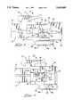
- FIG. 1is an isometric view of the connector of the present invention
- FIG. 2is an isometric view taken from the front of the connector of the present invention
- FIG. 3is a side view of the connector showing the longitudinal movement of the pivot lock housing
- FIG. 4is a side view showing the rotational movement of the pivot lock housing
- FIG. 5is a side view showing the prestage position of the pivot lock housing
- FIG. 6is a side view showing the fully assembled position of the pivot lock housing
- FIG. 7is an isometric view of the pin contact
- FIG. 8is an isometric view of the socket contact
- FIG. 9is a cross sectional view showing the pivot lock housing in the prestage position
- FIG. 10is a cross sectional view showing the pivot lock housing in the prestage position and the contacts loaded within the pivot lock housing;
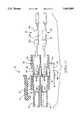
- FIG. 11is a cross sectional view showing the fully assembled connector.
- FIGS. 1 and 2show isometric views of the electrical connector of the current invention.
- the connector 10has a main housing 12 and a pivot lock housing 30.
- the main housingis similar to other electrical connectors in that it has contact silos 14 extending from a main body 18.
- the main body 18has a rearward end 20.
- Contact receiving passages 16extend in the rearward end 20 forward through the contact silos 14.
- the contact siloscan have polarization features as is shown in FIG. 2, however it is not necessary that these polarization features be present for the current invention.
- the main bodyalso has a latching arm 22 which extends forward from the main body to connect the connector 10 with the matable connector not shown.
- the contact silos 14are designed to be received within openings in the matable connector also not shown.
- the main body 18further has sidewalls 24. It is to be understood that other configurations of the main body of the electrical connector can have many different configurations and arrangements. For example, it is not necessary that the main body have a latching arm 22 or that the main body have contact silos 14 such as shown.
- the connector 10also has a pivot lock housing 30 having a main body 32.
- the main body 32has a forward end 36 and a rearward end 38.
- Second contact silos 40extend forwardly from the forward end 36.
- Second contact receiving passages 34extend from the rearward end 38 through the contact silos 40.
- the contact silos 40differ from the contact silos 14 on the main housing in that the contact silos 40 have slots 42 extending from the most forward end partially through towards the main body 32. These slots 42 form resilient latching fingers 44 on the silo.
- the resilient latching fingershave protrusions 46 which extend inwardly towards the center of the contact silo as is best shown in FIG. 9.
- the main body 32also has sidewalls 48 each with an arm 50 extending forwardly therefrom.
- the arm 50extends beyond the forward end 36 of the main body 32 and extends parallel to the contact silos 40.
- Each arm 50has several ratchet teeth 52a, 52b, 52c extending outwardly therefrom.
- Each ratchet toothhas a forwardly facing ramp surface and a rearwardly facing flat surface for engaging a latching arm.
- the main body 32also has a top wall 54 with block projections 56 extending upwardly therefrom.
- the block projections 56each have a pivot pin 58 extending outwardly therefrom.
- the pivot pin 58extends towards the sidewall 48.
- the main housing 12has two resilient latching arms 60 extending from sidewall 24. Each resilient arm 60 extends towards the rearward end 20 of the main housing 12. Each of the latching arms 60 has two parallel arms with recesses therebetween. A cross bar 61 extends perpendicularly between the two parallel arms and a latching bar 62 runs perpendicular along the rearward portion of the resilient latching am 60 between the two parallel arms. The latching bar 62 and the cross bar 61 are perpendicular to the main direction of the latching arm.
- the main housing 12also has a bottom wall 26 which is opposite to the mating latching arm 22.
- the bottom wall 26has two pivot guide members 64 extending rearwardly therefrom.
- the pivot guide 64has an outer loop 66 with a recess 68 therein.
- the pivot guide 64extends beyond the rearward end 20 of the main housing 12.
- the pivot guide 64receives the pivot pin 58 from the pivot lock housing 30 such that the pivot pin can move within the pivot guide both longitudinally and rotationally.
- the connector 10, having both the main housing 12 and the pivot lock housing 30,is molded in a one step process such that the pivot pins 58 are formed within the pivot guide 64 but not as an integral part of the pivot guide. Therefore, the main housing 12 and the pivot lock housing 30 are separate pieces that can move with respect to each other but are formed in one process. No separate assembly of the individual pieces is necessary.
- FIGS. 3 and 4illustrate how the pivot lock housing 30 can move with respect to the main housing 12.
- the pivot pins 58are received within the pivot guide 64 such that the pivot pins can move longitudinally therefore moving the pivot lock housing 30 with respect to the main housing 12, as is shown in FIG. 3 by arrow A.
- the cooperation of the pivot pin 58 and the pivot guide 64also allows the pivot lock 30 to rotate about the pivot pin 58, as is shown in FIG. 4 by arrow B.
- the pivot pin 58can move freely within the recess 68 of the pivot guide 64.
- the pivot pinonly being constrained by the outer loop 66 of the pivot guide 64.
- FIG. 5shows the pivot lock housing 30 in a prestage position.
- the pivot lock housing 30is rotated around so that it is in alignment with the main housing 12.
- the forwardmost ratchet tooth 52a on the arm 50engages the latching bar 62 on the resilient arm 60 of the main housing. That is the ratchet tooth is received in front of the latching bar 62 thereby securing the pivot lock in this prestage position.
- the significance of the prestage positionwill be described later on with reference to later figures.
- FIG. 6shows the pivot lock housing 30 moved into the final fully locked position.
- the pivot lock housing 30is pushed forward against the main housing 12 such that the most forward ratchet tooth 52a is received past the crossbar 61 on the latching am 60.
- the middle ratchet tooth 52bis received on the opposite side of the crossbar through the recess on the latching arm 60.
- the third ratchet tooth 52cis received also within the recess on the latching am 60.
- the third ratchet tooth 52cengages the latching bar 62 thereby double locking the pivot lock housing 30 in place against the main housing 12.
- the forward end 36 of the pivot lock housing 30is abutted against the rearward end 20 of the main body 12.
- the connector 10 of the present inventioncan accommodate both pin contacts 70 and socket contacts 80.
- the pin contactis shown in FIG. 7 and has a mating portion 72 and a crimp portion 74.
- An intermediate portion 76has a narrow section 78 with wider sections 79a and 79b both forward and behind the narrow sections 78.
- the socket contact in FIG. 8has a mating portion 82 and a crimp portion 84.
- the intermediate portion 86also has a narrow portion 88 which is flanked by wider portions 89a and 89b both to the rear and forward of the narrow portion.
- FIG. 9shows the connector 10 in a cross sectional view where the pivot lock housing 30 is in the prestage position. That is where the first ratchet tooth 52a has engaged the latching bar 62 on the housing.
- the contact 70is inserted from the rearward end 38 of the pivot lock housing, such that the contacts are received into the contact receiving passageway 34.
- FIG. 10shows the contacts fully loaded into the electrical connector 10 with the pivot lock housing 30 in the prestage position.
- the contact 70is received into the main housing 12 such that it is received through the contact receiving cavity 16.
- the protrusions 46 of the resilient latching fingers 44are received within the narrow portion 78 of the contact 70.
- the resilient fingers 44are deflected outwardly during the insertion of the contact as the wider portion 79a is being received through the resilient fingers.
- the resilient fingers 44then resile back to their initial position thereby securing the contact in the pivot lock housing 30.
- the contactis prevented from moving forward in the housing because the wider portion 79b along the rear of the contact engages protrusions thereby preventing the contacts from being moved forward in the housing.
- FIG. 11shows the pivot lock housing 30 in the fully assembled position that is where the third ratchet tooth 52c has been pushed into a position where it is engaging the latching bar 62. This is known as the fully assembled position.
- the second contact silos 40 on the pivot lock housing 30are fully received within the contact receiving passages 16.
- the forward end 36 of the pivot lock housing 30is received against the rearward end 20 of the main housing 12.
- the mating portion 72 of the contact 70is received into the portion of the contact receiving cavity 16 which resides in the contact silo 14 for electrically connecting with contacts in a matable connector (not shown).
- the contact receiving passageway 16becomes narrower as it approaches the contact silos 14.
- the contact 70When the connector is in the fully assembled position, the contact 70 is prevented from moving forward in the passageway because the wider portion 79a of the contact 70 engages the narrower portion of the contact receiving cavity 16 and is therefore prevented from being pushed more forward. Further, the resilient latching fingers 44 are securely held within the contact receiving passageway 16 thereby preventing them from deflecting outwardly. Therefore, the rearward wider portion 79 cannot move past the resilient latching fingers. The contact 70 is also prevented from being moved in a backward motion within the connector for the same reason. Because the resilient fingers 44 are prevented from deflecting outwardly by the contact receiving passageway 16, it is impossible for the wider portion to move through the latching fingers 44 past the protrusion 46.
- the contactis fully secured within the passageway and is prevented from moving either forwardly or rearwardly within the contact.
- the pivot lock housing 30is also prevented from being moved because it is secured by the resilient latching am 60.
- itis necessary to unlatch the pivot lock housing 30 from main body 12 and move the pivot lock housing 30 into the prestage position.
- the contacts 70can then be removed and replaced. Because the pivot lock housing 30 is not connected to the main body by a living hinge, it is reusable any number of times without damaging the locking housing due to overuse.
- the electrical connector 10can also accommodate socket contacts 80 in a similar manner as the pin contacts 70.
- the socket contacts 80are secured within the housing in the same manner.
- the contactscan be secured within the housing both from forward and rearward movement without using lances on the contacts.
- the locking mechanism used to secure these contacts within the housingis formed integrally with the housing and can be used over again. That is the pivot pin in freely moveable within the pivot guide therefore allowing the pivot lock housing 30 to be moved inward and outward of the main housing without damaging the guiding mechanism.
- a further advantageis that the pivot lock is formed at the same time as the main housing and no assembly of the pivot lock is necessary.
- An additional advantage of the present inventionis that because the locking fingers prevent the contact from moving rearwardly or forwardly, the contacts have a true position assurance for mating.
- the locking fingersprevent lateral movement of the contact if the wires which extend from the connector are pulled laterally, thereby keeping the contacts in the correct position for mating. If the contacts are pulled out of alignment, the contacts can stub against the contacts of the matable connector thereby preventing proper mating.
- the present inventioninsures that the contacts are maintained in the proper position for mating.
Landscapes
- Details Of Connecting Devices For Male And Female Coupling (AREA)
- Connector Housings Or Holding Contact Members (AREA)
Abstract
Description
The invention relates to an improved electrical connector housing and more particularly to an improved retention feature for the retention of the electrical contact within the housing.
Typically electrical connectors have retention means within the housing in order to secure contacts therein. A primary method of retaining the electrical terminal within the housing is to have a stamped out lance from the electrical terminal metal body which abuts a shoulder within the housing. A typical secondary retention method is profiled as a plastic moveable member which can move into place over the contact to lock the contact in place. Some of these moveable members are moved transversely over the actual direction, while some are designed as hinged flaps which are rotated into place. These flaps include plastic tabs which, when rotated, reside in a groove or gap within the contact to retain the contact in place. The hinged flaps are typically integrally molded with the connector housing and have live hinges about which the flap rotates. The live hinge is a thin plastic member connecting the flap and the connector housing. The live hinge can become broken or worn out over time thereby making the flap useless as a retention device.
U.S. Pat. No. 5,076,806 shows an electrical connector having a secondary lock member which is attached to the connector body by a live hinge. The secondary lock rotates about the live hinge into the proper position whereby tabs secure the contacts in place within the connector housing.
It would be an advantage to provide a locking feature which is secured to the housing but does not contain a live hinge that can break or wear over time. It would be a further advantage to provide the locking feature to fully secure the contacts within the connector housing so that the contacts can be formed without lances. That is where the locking feature provides all the necessary retaining feature to keep the contact secured within the connector housing.
The invention comprises an electrical connector having a connector housing with contact receiving passages to receive contacts therein and a guide member. A lock housing has a pivot member wherein the pivot member and the guide member cooperate to secure the lock housing to the connector housing and to allow the lock housing to rotate and move longitudinally with respect to the connector housing. The lock housing having a first position with respect to the connector housing wherein the contacts can be loaded into the housing. The lock housing having a second position wherein the contacts are secured within the housing for electrical connection with a matable connector.
Embodiments of the present invention will now be described with reference to the accompanying drawings in which:
FIG. 1 is an isometric view of the connector of the present invention;
FIG. 2 is an isometric view taken from the front of the connector of the present invention;
FIG. 3 is a side view of the connector showing the longitudinal movement of the pivot lock housing;
FIG. 4 is a side view showing the rotational movement of the pivot lock housing;
FIG. 5 is a side view showing the prestage position of the pivot lock housing;
FIG. 6 is a side view showing the fully assembled position of the pivot lock housing;
FIG. 7 is an isometric view of the pin contact;
FIG. 8 is an isometric view of the socket contact;
FIG. 9 is a cross sectional view showing the pivot lock housing in the prestage position;
FIG. 10 is a cross sectional view showing the pivot lock housing in the prestage position and the contacts loaded within the pivot lock housing; and
FIG. 11 is a cross sectional view showing the fully assembled connector.
FIGS. 1 and 2 show isometric views of the electrical connector of the current invention. Theconnector 10 has amain housing 12 and apivot lock housing 30. The main housing is similar to other electrical connectors in that it hascontact silos 14 extending from amain body 18. Themain body 18 has arearward end 20. Contact receivingpassages 16 extend in therearward end 20 forward through thecontact silos 14. The contact silos can have polarization features as is shown in FIG. 2, however it is not necessary that these polarization features be present for the current invention. The main body also has alatching arm 22 which extends forward from the main body to connect theconnector 10 with the matable connector not shown. Thecontact silos 14 are designed to be received within openings in the matable connector also not shown. Themain body 18 further hassidewalls 24. It is to be understood that other configurations of the main body of the electrical connector can have many different configurations and arrangements. For example, it is not necessary that the main body have alatching arm 22 or that the main body havecontact silos 14 such as shown.
Theconnector 10 also has apivot lock housing 30 having amain body 32. Themain body 32 has aforward end 36 and arearward end 38.Second contact silos 40 extend forwardly from theforward end 36. Secondcontact receiving passages 34 extend from therearward end 38 through thecontact silos 40. Thecontact silos 40 differ from thecontact silos 14 on the main housing in that thecontact silos 40 haveslots 42 extending from the most forward end partially through towards themain body 32. Theseslots 42 formresilient latching fingers 44 on the silo. The resilient latching fingers haveprotrusions 46 which extend inwardly towards the center of the contact silo as is best shown in FIG. 9. Themain body 32 also hassidewalls 48 each with anarm 50 extending forwardly therefrom. Thearm 50 extends beyond theforward end 36 of themain body 32 and extends parallel to thecontact silos 40. Eacharm 50 hasseveral ratchet teeth main body 32 also has atop wall 54 withblock projections 56 extending upwardly therefrom. Theblock projections 56 each have apivot pin 58 extending outwardly therefrom. Thepivot pin 58 extends towards thesidewall 48.
Themain housing 12 has two resilient latchingarms 60 extending fromsidewall 24. Eachresilient arm 60 extends towards therearward end 20 of themain housing 12. Each of thelatching arms 60 has two parallel arms with recesses therebetween. Across bar 61 extends perpendicularly between the two parallel arms and alatching bar 62 runs perpendicular along the rearward portion of the resilient latching am 60 between the two parallel arms. The latchingbar 62 and thecross bar 61 are perpendicular to the main direction of the latching arm.
Themain housing 12 also has abottom wall 26 which is opposite to themating latching arm 22. Thebottom wall 26 has twopivot guide members 64 extending rearwardly therefrom. Thepivot guide 64 has anouter loop 66 with arecess 68 therein. Thepivot guide 64 extends beyond therearward end 20 of themain housing 12. Thepivot guide 64 receives thepivot pin 58 from thepivot lock housing 30 such that the pivot pin can move within the pivot guide both longitudinally and rotationally.
Theconnector 10, having both themain housing 12 and thepivot lock housing 30, is molded in a one step process such that the pivot pins 58 are formed within thepivot guide 64 but not as an integral part of the pivot guide. Therefore, themain housing 12 and thepivot lock housing 30 are separate pieces that can move with respect to each other but are formed in one process. No separate assembly of the individual pieces is necessary.
FIGS. 3 and 4 illustrate how thepivot lock housing 30 can move with respect to themain housing 12. The pivot pins 58 are received within thepivot guide 64 such that the pivot pins can move longitudinally therefore moving thepivot lock housing 30 with respect to themain housing 12, as is shown in FIG. 3 by arrow A. The cooperation of thepivot pin 58 and thepivot guide 64 also allows thepivot lock 30 to rotate about thepivot pin 58, as is shown in FIG. 4 by arrow B. Thepivot pin 58 can move freely within therecess 68 of thepivot guide 64. The pivot pin only being constrained by theouter loop 66 of thepivot guide 64.
FIG. 5 shows thepivot lock housing 30 in a prestage position. In this position thepivot lock housing 30 is rotated around so that it is in alignment with themain housing 12. Further, theforwardmost ratchet tooth 52a on thearm 50 engages the latchingbar 62 on theresilient arm 60 of the main housing. That is the ratchet tooth is received in front of the latchingbar 62 thereby securing the pivot lock in this prestage position. The significance of the prestage position will be described later on with reference to later figures.
FIG. 6 shows thepivot lock housing 30 moved into the final fully locked position. The pivot lockhousing 30 is pushed forward against themain housing 12 such that the mostforward ratchet tooth 52a is received past thecrossbar 61 on the latchingam 60. Themiddle ratchet tooth 52b is received on the opposite side of the crossbar through the recess on the latchingarm 60. Further thethird ratchet tooth 52c is received also within the recess on the latchingam 60. Thethird ratchet tooth 52c engages the latchingbar 62 thereby double locking thepivot lock housing 30 in place against themain housing 12. Theforward end 36 of thepivot lock housing 30 is abutted against therearward end 20 of themain body 12.
Theconnector 10 of the present invention can accommodate bothpin contacts 70 andsocket contacts 80. The pin contact is shown in FIG. 7 and has amating portion 72 and acrimp portion 74. Anintermediate portion 76 has anarrow section 78 withwider sections narrow sections 78. Similarly the socket contact in FIG. 8 has amating portion 82 and acrimp portion 84. Theintermediate portion 86 also has anarrow portion 88 which is flanked bywider portions
FIG. 9 shows theconnector 10 in a cross sectional view where thepivot lock housing 30 is in the prestage position. That is where thefirst ratchet tooth 52a has engaged the latchingbar 62 on the housing. Thecontact 70 is inserted from therearward end 38 of the pivot lock housing, such that the contacts are received into thecontact receiving passageway 34.
FIG. 10 shows the contacts fully loaded into theelectrical connector 10 with thepivot lock housing 30 in the prestage position. As can be seen, thecontact 70 is received into themain housing 12 such that it is received through thecontact receiving cavity 16. Theprotrusions 46 of the resilient latchingfingers 44 are received within thenarrow portion 78 of thecontact 70. Theresilient fingers 44 are deflected outwardly during the insertion of the contact as thewider portion 79a is being received through the resilient fingers. Theresilient fingers 44 then resile back to their initial position thereby securing the contact in thepivot lock housing 30. The contact is prevented from moving forward in the housing because thewider portion 79b along the rear of the contact engages protrusions thereby preventing the contacts from being moved forward in the housing.
FIG. 11 shows thepivot lock housing 30 in the fully assembled position that is where thethird ratchet tooth 52c has been pushed into a position where it is engaging the latchingbar 62. This is known as the fully assembled position. In this position, thesecond contact silos 40 on thepivot lock housing 30 are fully received within thecontact receiving passages 16. Theforward end 36 of thepivot lock housing 30 is received against therearward end 20 of themain housing 12. Further, themating portion 72 of thecontact 70 is received into the portion of thecontact receiving cavity 16 which resides in thecontact silo 14 for electrically connecting with contacts in a matable connector (not shown). As can be seen in the drawings, thecontact receiving passageway 16 becomes narrower as it approaches thecontact silos 14. When the connector is in the fully assembled position, thecontact 70 is prevented from moving forward in the passageway because thewider portion 79a of thecontact 70 engages the narrower portion of thecontact receiving cavity 16 and is therefore prevented from being pushed more forward. Further, the resilient latchingfingers 44 are securely held within thecontact receiving passageway 16 thereby preventing them from deflecting outwardly. Therefore, the rearward wider portion 79 cannot move past the resilient latching fingers. Thecontact 70 is also prevented from being moved in a backward motion within the connector for the same reason. Because theresilient fingers 44 are prevented from deflecting outwardly by thecontact receiving passageway 16, it is impossible for the wider portion to move through the latchingfingers 44 past theprotrusion 46. Therefore, the contact is fully secured within the passageway and is prevented from moving either forwardly or rearwardly within the contact. The pivot lockhousing 30 is also prevented from being moved because it is secured by theresilient latching am 60. In order to remove the contacts from the housing, it is necessary to unlatch thepivot lock housing 30 frommain body 12 and move thepivot lock housing 30 into the prestage position. Thecontacts 70 can then be removed and replaced. Because thepivot lock housing 30 is not connected to the main body by a living hinge, it is reusable any number of times without damaging the locking housing due to overuse.
Theelectrical connector 10 can also accommodatesocket contacts 80 in a similar manner as thepin contacts 70. Thesocket contacts 80 are secured within the housing in the same manner.
The advantages of the present invention are that the contacts can be secured within the housing both from forward and rearward movement without using lances on the contacts. Further, the locking mechanism used to secure these contacts within the housing is formed integrally with the housing and can be used over again. That is the pivot pin in freely moveable within the pivot guide therefore allowing thepivot lock housing 30 to be moved inward and outward of the main housing without damaging the guiding mechanism. A further advantage is that the pivot lock is formed at the same time as the main housing and no assembly of the pivot lock is necessary.
An additional advantage of the present invention is that because the locking fingers prevent the contact from moving rearwardly or forwardly, the contacts have a true position assurance for mating. The locking fingers prevent lateral movement of the contact if the wires which extend from the connector are pulled laterally, thereby keeping the contacts in the correct position for mating. If the contacts are pulled out of alignment, the contacts can stub against the contacts of the matable connector thereby preventing proper mating. The present invention insures that the contacts are maintained in the proper position for mating.
It is thought that the improved electrical connector of the present invention and many of its attendant advantages will be understood from the foregoing description. It is apparent that various changes may be made in the form, construction, and arrangement of parts thereof without departing from the spirit or scope of the invention, or sacrificing all of its material advantages.
Claims (11)
1. An electrical connector comprising:
a connector housing having contact receiving passages to receive contacts therein and a guide member;
a lock housing having a pivot member wherein the pivot member and the guide member cooperate to secure the lock housing to the connector housing and to allow the lock housing to rotate and move longitudinally with respect to the connector housing, the lock housing having a first position with respect to the connector housing wherein the contacts can be loaded into the housing, the lock housing having a second position wherein the contacts are secured within the housing for electrical connection with a matable connector.
2. The electrical connector of claim 1, wherein the guide member has a recess, the pivot being received within the recess.
3. The electrical connector of claim 2, wherein the guide member has an outer loop which encompasses the recess, the guide member extending rearwardly from the connector housing.
4. The electrical connector of claim 1, wherein the lock housing has a rearward end and a forward end with contact silos extending from the forward end, and contact receiving passages extend through the lock housing from the rearward end through the contact silos.
5. The connector of claim 4, wherein the contact silos having latching fingers with protrusions on ends thereof, the latching fingers being deflectable to receive the contacts and secure the contacts thereon.
6. The electrical connector of claim 5, wherein the contact silos are receivable within the contact receiving passages of the connector housing.
7. The electrical connector of claim 6, wherein the lock housing has an arm with ratchet teeth thereon, the arm extending forwardly from the lock housing, and the connector housing has a resilient latching arm to engage the ratchet teeth.
8. The electrical connector of claim 7, wherein the first position is a prestage position where the ratchet teeth engage the resilient latching arm and the contacts being inserted through the contact receiving passages of the lock housing, the latching fingers being deflectable to receive the contacts and then resile to their normal position to secure the contacts therein, the second position being a fully assembled position wherein the contact silos are received within the contact receiving passages of the connector housing thereby preventing deflection of the latching fingers and securing the contacts therein and the resilient latching arm cooperates with the ratchet teeth to secure the lock housing in the fully assembled position.
9. The electrical connector of claim 1, wherein the lock housing has an arm with ratchet teeth thereon, the arm extending forwardly from the lock housing, the connector housing having a resilient latching arm to engage the ratchet teeth, the resilient latching arm and the ratchet teeth on the arm cooperate to secure the lock housing in the first position wherein the contacts can be removably loaded into the lock housing, the resilient latching arm and the ratchet teeth on the arm further cooperate to secure the lock housing in the second position in which the contacts are fully secured within the connector housing for mating with the matable connector.
10. The electrical connector of claim 9, wherein the lock housing has a rearward end and a forward end with contact silos extending from the forward end, and contact receiving passages extend through the lock housing from the rearward end through the contact silos.
11. The electrical connector of claim 10, wherein the contact silos have latching fingers with protrusions thereon, the latching fingers being deflectable while in the first position to receive the contacts therein, and when the pivot housing is in the second position, the contact silos are received within the contact receiving passages of the connector housing thereby preventing deflection of the latching fingers and preventing the contacts from being removed from the connector housing.
Priority Applications (8)
| Application Number | Priority Date | Filing Date | Title |
|---|---|---|---|
| US08/606,709US5643009A (en) | 1996-02-26 | 1996-02-26 | Electrical connector having a pivot lock |
| DE69704555TDE69704555T2 (en) | 1996-02-26 | 1997-02-26 | ELECTRIC CONNECTOR WITH ROTATING LOCK |
| AU19671/97AAU715014B2 (en) | 1996-02-26 | 1997-02-26 | An electrical connector having a pivot lock |
| CN97192582ACN1113435C (en) | 1996-02-26 | 1997-02-26 | Electrical connector having pivot lock |
| JP53033997AJP3754086B2 (en) | 1996-02-26 | 1997-02-26 | Electrical connector with pivot lock |
| PCT/US1997/002731WO1997031407A1 (en) | 1996-02-26 | 1997-02-26 | An electrical connector having a pivot lock |
| EP97907755AEP0883911B1 (en) | 1996-02-26 | 1997-02-26 | An electrical connector having a pivot lock |
| KR1019980706826AKR100477390B1 (en) | 1996-02-26 | 1997-02-26 | Electrical connector with pivot lock |
Applications Claiming Priority (1)
| Application Number | Priority Date | Filing Date | Title |
|---|---|---|---|
| US08/606,709US5643009A (en) | 1996-02-26 | 1996-02-26 | Electrical connector having a pivot lock |
Publications (1)
| Publication Number | Publication Date |
|---|---|
| US5643009Atrue US5643009A (en) | 1997-07-01 |
Family
ID=24429133
Family Applications (1)
| Application Number | Title | Priority Date | Filing Date |
|---|---|---|---|
| US08/606,709Expired - LifetimeUS5643009A (en) | 1996-02-26 | 1996-02-26 | Electrical connector having a pivot lock |
Country Status (8)
| Country | Link |
|---|---|
| US (1) | US5643009A (en) |
| EP (1) | EP0883911B1 (en) |
| JP (1) | JP3754086B2 (en) |
| KR (1) | KR100477390B1 (en) |
| CN (1) | CN1113435C (en) |
| AU (1) | AU715014B2 (en) |
| DE (1) | DE69704555T2 (en) |
| WO (1) | WO1997031407A1 (en) |
Cited By (73)
| Publication number | Priority date | Publication date | Assignee | Title |
|---|---|---|---|---|
| US5941737A (en)* | 1997-02-10 | 1999-08-24 | Yazaki Corporation | Double retaining connector |
| US6095826A (en)* | 1997-02-21 | 2000-08-01 | Berg Technology, Inc. | Press fit circuit board connector |
| US6139336A (en)* | 1996-11-14 | 2000-10-31 | Berg Technology, Inc. | High density connector having a ball type of contact surface |
| US6146203A (en)* | 1995-06-12 | 2000-11-14 | Berg Technology, Inc. | Low cross talk and impedance controlled electrical connector |
| US6164983A (en)* | 1996-10-10 | 2000-12-26 | Berg Technology, Inc. | High density connector |
| US6325644B1 (en) | 1996-10-10 | 2001-12-04 | Berg Technology, Inc. | High density connector and method of manufacture |
| US6443767B1 (en)* | 1999-08-06 | 2002-09-03 | Yazaki Corporation | Connector with integral cover |
| US20020146281A1 (en)* | 2001-02-27 | 2002-10-10 | Yazaki Corporation | Connector |
| US6688921B2 (en)* | 2001-10-10 | 2004-02-10 | Thomas & Betts International, Inc. | Thermoplastic molded set screw connector assembly |
| US20040110427A1 (en)* | 2002-08-23 | 2004-06-10 | Xiankui Shi | Cable end connector and method of assembling the same |
| US20040115978A1 (en)* | 2002-09-18 | 2004-06-17 | Kayvan Hedayat | Trailer tow connector assembly |
| US6939173B1 (en) | 1995-06-12 | 2005-09-06 | Fci Americas Technology, Inc. | Low cross talk and impedance controlled electrical connector with solder masses |
| US20050221675A1 (en)* | 2003-07-16 | 2005-10-06 | Rathburn James J | Fine pitch electrical interconnect assembly |
| US20050239308A1 (en)* | 2002-09-18 | 2005-10-27 | Dave Cummings | Trailer tow connector assembly |
| US20060035483A1 (en)* | 2003-07-16 | 2006-02-16 | Gryphics, Inc. | Fine pitch electrical interconnect assembly |
| US7090532B1 (en)* | 2005-04-04 | 2006-08-15 | Michel Kaine | Rocket for electrical connectors |
| US20060199441A1 (en)* | 2005-03-07 | 2006-09-07 | Industria Lombarda Materiale Elettrico I.L.M.E. S.P.A. | Electrical connector element for conductors with crimped contacts |
| US20060199424A1 (en)* | 2005-03-03 | 2006-09-07 | Tyco Electronics Corporation | Pluggable screwless wire connector system |
| US20070054535A1 (en)* | 2005-09-02 | 2007-03-08 | Tyco Electronics Corporation | Connector assembly including provision for body clip |
| US20070054543A1 (en)* | 2005-09-02 | 2007-03-08 | Tyco Electronics Corporation | Three position electrical connector assembly |
| US20070059973A1 (en)* | 2005-09-15 | 2007-03-15 | Tyco Electronics Corporation | Hot plug wire contact and connector assembly |
| US20070099480A1 (en)* | 2005-03-03 | 2007-05-03 | Tyco Electronics Corporation | Pluggable screwless wire connector system |
| US20070207679A1 (en)* | 2006-03-01 | 2007-09-06 | Kleinschmidt Stephan | Electric contact |
| US20080070441A1 (en)* | 2004-09-29 | 2008-03-20 | Frederic Chazottes | Locking Device for Connector Elements and a Connector Provided with Said Device |
| WO2007097879A3 (en)* | 2006-02-21 | 2008-06-12 | Fci Americas Technology Inc | Electrical connectors having power contacts with alignment features |
| US7425145B2 (en) | 2006-05-26 | 2008-09-16 | Fci Americas Technology, Inc. | Connectors and contacts for transmitting electrical power |
| US7476108B2 (en) | 2004-12-22 | 2009-01-13 | Fci Americas Technology, Inc. | Electrical power connectors with cooling features |
| US20090061693A1 (en)* | 2007-09-05 | 2009-03-05 | Irish Kenneth G | Connector with flexible region |
| US20090130902A1 (en)* | 2007-11-15 | 2009-05-21 | Tyco Electronics Corporation | Multi position electrical connector assembly |
| US7537461B2 (en) | 2003-07-16 | 2009-05-26 | Gryphics, Inc. | Fine pitch electrical interconnect assembly |
| US7541135B2 (en) | 2005-04-05 | 2009-06-02 | Fci Americas Technology, Inc. | Power contact having conductive plates with curved portions contact beams and board tails |
| US7641500B2 (en) | 2007-04-04 | 2010-01-05 | Fci Americas Technology, Inc. | Power cable connector system |
| USD608293S1 (en) | 2009-01-16 | 2010-01-19 | Fci Americas Technology, Inc. | Vertical electrical connector |
| USD610548S1 (en) | 2009-01-16 | 2010-02-23 | Fci Americas Technology, Inc. | Right-angle electrical connector |
| EP2182591A1 (en)* | 2008-11-04 | 2010-05-05 | Coninvers GmbH | Electric plug connector |
| US7726982B2 (en) | 2006-06-15 | 2010-06-01 | Fci Americas Technology, Inc. | Electrical connectors with air-circulation features |
| USD618181S1 (en) | 2009-04-03 | 2010-06-22 | Fci Americas Technology, Inc. | Asymmetrical electrical connector |
| USD618180S1 (en) | 2009-04-03 | 2010-06-22 | Fci Americas Technology, Inc. | Asymmetrical electrical connector |
| USD619099S1 (en) | 2009-01-30 | 2010-07-06 | Fci Americas Technology, Inc. | Electrical connector |
| US7749009B2 (en) | 2005-01-31 | 2010-07-06 | Fci Americas Technology, Inc. | Surface-mount connector |
| US7762857B2 (en) | 2007-10-01 | 2010-07-27 | Fci Americas Technology, Inc. | Power connectors with contact-retention features |
| US7862359B2 (en) | 2003-12-31 | 2011-01-04 | Fci Americas Technology Llc | Electrical power contacts and connectors comprising same |
| US7905731B2 (en) | 2007-05-21 | 2011-03-15 | Fci Americas Technology, Inc. | Electrical connector with stress-distribution features |
| USD641709S1 (en) | 2009-01-16 | 2011-07-19 | Fci Americas Technology Llc | Vertical electrical connector |
| US20110237112A1 (en)* | 2010-03-29 | 2011-09-29 | Hon Hai Precision Industry Co., Ltd. | Electrical connector assembly wth a latch easy to be operated |
| US8044502B2 (en) | 2006-03-20 | 2011-10-25 | Gryphics, Inc. | Composite contact for fine pitch electrical interconnect assembly |
| US8062051B2 (en) | 2008-07-29 | 2011-11-22 | Fci Americas Technology Llc | Electrical communication system having latching and strain relief features |
| WO2012146766A1 (en)* | 2011-04-28 | 2012-11-01 | Fci Automotive Holding | Multicontact body, electrical contact, electrical connector device and assembly method |
| US8323049B2 (en) | 2009-01-30 | 2012-12-04 | Fci Americas Technology Llc | Electrical connector having power contacts |
| WO2013027861A1 (en)* | 2011-08-23 | 2013-02-28 | Yazaki Corporation | Connector |
| US20130203299A1 (en)* | 2010-09-27 | 2013-08-08 | Tyco Electronics Amp Gmbh | Contact Housing For Electrical Contact Units, Electrical Plug Connector or Mating Connector as Well as an Assembled Electrical Conductor |
| USD718253S1 (en) | 2012-04-13 | 2014-11-25 | Fci Americas Technology Llc | Electrical cable connector |
| US8905651B2 (en) | 2012-01-31 | 2014-12-09 | Fci | Dismountable optical coupling device |
| USD720698S1 (en) | 2013-03-15 | 2015-01-06 | Fci Americas Technology Llc | Electrical cable connector |
| US8944831B2 (en) | 2012-04-13 | 2015-02-03 | Fci Americas Technology Llc | Electrical connector having ribbed ground plate with engagement members |
| USD727268S1 (en) | 2012-04-13 | 2015-04-21 | Fci Americas Technology Llc | Vertical electrical connector |
| USD727852S1 (en) | 2012-04-13 | 2015-04-28 | Fci Americas Technology Llc | Ground shield for a right angle electrical connector |
| US9048583B2 (en) | 2009-03-19 | 2015-06-02 | Fci Americas Technology Llc | Electrical connector having ribbed ground plate |
| USD733662S1 (en) | 2013-01-25 | 2015-07-07 | Fci Americas Technology Llc | Connector housing for electrical connector |
| USD746236S1 (en) | 2012-07-11 | 2015-12-29 | Fci Americas Technology Llc | Electrical connector housing |
| EP2980924A1 (en)* | 2014-07-29 | 2016-02-03 | Japan Aviation Electronics Industry Limited | Connector |
| US9257778B2 (en) | 2012-04-13 | 2016-02-09 | Fci Americas Technology | High speed electrical connector |
| EP3021423A1 (en)* | 2014-11-13 | 2016-05-18 | Tyco Electronics Corporation | Electrical connector |
| US9543703B2 (en) | 2012-07-11 | 2017-01-10 | Fci Americas Technology Llc | Electrical connector with reduced stack height |
| US20180219324A1 (en)* | 2015-07-27 | 2018-08-02 | HARTING Electronics GmbH | Electrical plug connector |
| US20190312394A1 (en)* | 2018-04-04 | 2019-10-10 | Commscope Technologies Llc | Ganged coaxial connector assembly |
| US20190363481A1 (en)* | 2018-04-04 | 2019-11-28 | Commscope Technologies Llc | Ganged coaxial connector assembly |
| US20200014139A1 (en)* | 2018-07-09 | 2020-01-09 | Te Connectivity Germany Gmbh | Contact Device and Contact System |
| US20200259304A1 (en)* | 2017-10-09 | 2020-08-13 | Bae Systems Plc | Plug assembly |
| US20210305724A1 (en)* | 2020-03-24 | 2021-09-30 | Hirose Electric Co., Ltd. | Cable connector including cable holder, and method of manufacturing cable connector |
| FR3113786A1 (en)* | 2020-09-03 | 2022-03-04 | Aptiv Technologies Limited | Improved contact positioning contact and connector housing |
| CN114389063A (en)* | 2020-10-06 | 2022-04-22 | 泰连服务有限公司 | Cable harness assembly with shielded twisted pair cable |
| US11527846B2 (en) | 2016-02-12 | 2022-12-13 | Commscope Technologies Llc | Ganged coaxial connector assembly |
Families Citing this family (4)
| Publication number | Priority date | Publication date | Assignee | Title |
|---|---|---|---|---|
| DE10044790C1 (en)* | 2000-09-11 | 2002-04-04 | Contact Gmbh | Insulating body for a connector for the transmission of optical and electrical signals |
| JP5046395B2 (en) | 2008-08-20 | 2012-10-10 | タイコエレクトロニクスジャパン合同会社 | Electrical connector |
| DE102011054563B3 (en)* | 2011-10-18 | 2013-01-24 | HARTING Electronics GmbH | Connectors |
| DE102016120304B4 (en) | 2016-10-25 | 2020-10-08 | Lisa Dräxlmaier GmbH | ANGLED CONNECTOR AND METHOD FOR MANUFACTURING IT |
Citations (15)
| Publication number | Priority date | Publication date | Assignee | Title |
|---|---|---|---|---|
| US3838382A (en)* | 1973-07-13 | 1974-09-24 | Itt | Retention system for electrical contacts |
| US4045110A (en)* | 1975-10-04 | 1977-08-30 | Amp Incorporated | Electrical connector housings |
| US4443048A (en)* | 1981-10-02 | 1984-04-17 | Amp Incorporated | Assembly with verification feature |
| US4544220A (en)* | 1983-12-28 | 1985-10-01 | Amp Incorporated | Connector having means for positively seating contacts |
| US4583805A (en)* | 1982-12-18 | 1986-04-22 | Grote & Hartmann Gmbh & Co. Kg | Locking arrangement for electrical contact element insertable into housing chamber |
| US4758183A (en)* | 1986-03-31 | 1988-07-19 | Amp Incorporated | Electrical connector with a wire cover |
| US4820204A (en)* | 1986-12-12 | 1989-04-11 | Amp Incorporated | Modular electrical connector assembly |
| US4900277A (en)* | 1987-10-19 | 1990-02-13 | Yazaki Corporation | Connector |
| US4944688A (en)* | 1989-09-25 | 1990-07-31 | Amp Incorporated | Programmable sealed connector |
| US4973268A (en)* | 1989-10-10 | 1990-11-27 | Amp Incorporated | Multi-contact electrical connector with secondary lock |
| US4979913A (en)* | 1989-10-26 | 1990-12-25 | Amp Incorporated | Electrical connector with hinged secondary lock |
| US4988307A (en)* | 1989-10-10 | 1991-01-29 | Itt Corporation | Circuit shorting connector |
| US5076806A (en)* | 1989-10-24 | 1991-12-31 | Amp Incorporated | Electrical connector having improved secondary retention means |
| US5122077A (en)* | 1988-11-24 | 1992-06-16 | Yazaki Corporation | Multi-stage connector |
| US5501619A (en)* | 1993-05-07 | 1996-03-26 | Sumitomo Wiring Systems, Ltd. | Connector |
Family Cites Families (2)
| Publication number | Priority date | Publication date | Assignee | Title |
|---|---|---|---|---|
| GB2115625A (en)* | 1982-02-26 | 1983-09-07 | Amp Inc | Mounting electrical terminals in a connector housing |
| JPH06236777A (en)* | 1993-02-10 | 1994-08-23 | Sumitomo Wiring Syst Ltd | Connector |
- 1996
- 1996-02-26USUS08/606,709patent/US5643009A/ennot_activeExpired - Lifetime
- 1997
- 1997-02-26KRKR1019980706826Apatent/KR100477390B1/ennot_activeExpired - Lifetime
- 1997-02-26CNCN97192582Apatent/CN1113435C/ennot_activeExpired - Lifetime
- 1997-02-26DEDE69704555Tpatent/DE69704555T2/ennot_activeExpired - Lifetime
- 1997-02-26EPEP97907755Apatent/EP0883911B1/ennot_activeExpired - Lifetime
- 1997-02-26JPJP53033997Apatent/JP3754086B2/ennot_activeExpired - Fee Related
- 1997-02-26WOPCT/US1997/002731patent/WO1997031407A1/enactiveIP Right Grant
- 1997-02-26AUAU19671/97Apatent/AU715014B2/ennot_activeCeased
Patent Citations (16)
| Publication number | Priority date | Publication date | Assignee | Title |
|---|---|---|---|---|
| US3838382A (en)* | 1973-07-13 | 1974-09-24 | Itt | Retention system for electrical contacts |
| US4045110A (en)* | 1975-10-04 | 1977-08-30 | Amp Incorporated | Electrical connector housings |
| US4443048A (en)* | 1981-10-02 | 1984-04-17 | Amp Incorporated | Assembly with verification feature |
| US4583805A (en)* | 1982-12-18 | 1986-04-22 | Grote & Hartmann Gmbh & Co. Kg | Locking arrangement for electrical contact element insertable into housing chamber |
| US4660915A (en)* | 1982-12-18 | 1987-04-28 | Grote & Hartmann Gmbh & Co. Kg | Locking arrangement for electrical contact element insertable into housing chamber |
| US4544220A (en)* | 1983-12-28 | 1985-10-01 | Amp Incorporated | Connector having means for positively seating contacts |
| US4758183A (en)* | 1986-03-31 | 1988-07-19 | Amp Incorporated | Electrical connector with a wire cover |
| US4820204A (en)* | 1986-12-12 | 1989-04-11 | Amp Incorporated | Modular electrical connector assembly |
| US4900277A (en)* | 1987-10-19 | 1990-02-13 | Yazaki Corporation | Connector |
| US5122077A (en)* | 1988-11-24 | 1992-06-16 | Yazaki Corporation | Multi-stage connector |
| US4944688A (en)* | 1989-09-25 | 1990-07-31 | Amp Incorporated | Programmable sealed connector |
| US4973268A (en)* | 1989-10-10 | 1990-11-27 | Amp Incorporated | Multi-contact electrical connector with secondary lock |
| US4988307A (en)* | 1989-10-10 | 1991-01-29 | Itt Corporation | Circuit shorting connector |
| US5076806A (en)* | 1989-10-24 | 1991-12-31 | Amp Incorporated | Electrical connector having improved secondary retention means |
| US4979913A (en)* | 1989-10-26 | 1990-12-25 | Amp Incorporated | Electrical connector with hinged secondary lock |
| US5501619A (en)* | 1993-05-07 | 1996-03-26 | Sumitomo Wiring Systems, Ltd. | Connector |
Cited By (140)
| Publication number | Priority date | Publication date | Assignee | Title |
|---|---|---|---|---|
| US6939173B1 (en) | 1995-06-12 | 2005-09-06 | Fci Americas Technology, Inc. | Low cross talk and impedance controlled electrical connector with solder masses |
| US6146203A (en)* | 1995-06-12 | 2000-11-14 | Berg Technology, Inc. | Low cross talk and impedance controlled electrical connector |
| US7476110B2 (en) | 1996-10-10 | 2009-01-13 | Fci Americas Technology, Inc. | High density connector and method of manufacture |
| US6164983A (en)* | 1996-10-10 | 2000-12-26 | Berg Technology, Inc. | High density connector |
| US6325644B1 (en) | 1996-10-10 | 2001-12-04 | Berg Technology, Inc. | High density connector and method of manufacture |
| US6358068B1 (en)* | 1996-10-10 | 2002-03-19 | Fci Americas Technology, Inc. | Stress resistant connector and method for reducing stress in housing thereof |
| US8167630B2 (en) | 1996-10-10 | 2012-05-01 | Fci Americas Technology Llc | High density connector and method of manufacture |
| US7186123B2 (en) | 1996-10-10 | 2007-03-06 | Fci Americas Technology, Inc. | High density connector and method of manufacture |
| US6139336A (en)* | 1996-11-14 | 2000-10-31 | Berg Technology, Inc. | High density connector having a ball type of contact surface |
| US6247635B1 (en) | 1996-11-14 | 2001-06-19 | Berg Technology, Inc. | High density connector having a ball type of contact surface |
| US5941737A (en)* | 1997-02-10 | 1999-08-24 | Yazaki Corporation | Double retaining connector |
| US6095826A (en)* | 1997-02-21 | 2000-08-01 | Berg Technology, Inc. | Press fit circuit board connector |
| US6443767B1 (en)* | 1999-08-06 | 2002-09-03 | Yazaki Corporation | Connector with integral cover |
| EP1235306A3 (en)* | 2001-02-27 | 2003-12-17 | Yazaki Corporation | Electrical connector |
| US20020146281A1 (en)* | 2001-02-27 | 2002-10-10 | Yazaki Corporation | Connector |
| US6786768B2 (en) | 2001-02-27 | 2004-09-07 | Yazaki Corporation | Electrical connection assembly |
| US20040142588A1 (en)* | 2001-10-10 | 2004-07-22 | Thomas & Betts Corporation. | Thermoplastic molded set screw connector assembly |
| US6817910B2 (en) | 2001-10-10 | 2004-11-16 | Thomas & Betts International, Inc. | Thermoplastic molded set screw connector assembly |
| US6688921B2 (en)* | 2001-10-10 | 2004-02-10 | Thomas & Betts International, Inc. | Thermoplastic molded set screw connector assembly |
| US7892048B2 (en)* | 2002-08-23 | 2011-02-22 | Hon Hai Precision Ind. Co., Ltd. | Cable end connector and method of assembling the same |
| US20040110427A1 (en)* | 2002-08-23 | 2004-06-10 | Xiankui Shi | Cable end connector and method of assembling the same |
| US20050239308A1 (en)* | 2002-09-18 | 2005-10-27 | Dave Cummings | Trailer tow connector assembly |
| US20040115978A1 (en)* | 2002-09-18 | 2004-06-17 | Kayvan Hedayat | Trailer tow connector assembly |
| US7331792B2 (en) | 2002-09-18 | 2008-02-19 | Stoneridge Control Devices, Inc. | Trailer tow connector assembly |
| US7326064B2 (en) | 2003-07-16 | 2008-02-05 | Gryphics, Inc. | Fine pitch electrical interconnect assembly |
| US20050221675A1 (en)* | 2003-07-16 | 2005-10-06 | Rathburn James J | Fine pitch electrical interconnect assembly |
| US20060035483A1 (en)* | 2003-07-16 | 2006-02-16 | Gryphics, Inc. | Fine pitch electrical interconnect assembly |
| US7537461B2 (en) | 2003-07-16 | 2009-05-26 | Gryphics, Inc. | Fine pitch electrical interconnect assembly |
| US7422439B2 (en) | 2003-07-16 | 2008-09-09 | Gryphics, Inc. | Fine pitch electrical interconnect assembly |
| US7297003B2 (en) | 2003-07-16 | 2007-11-20 | Gryphics, Inc. | Fine pitch electrical interconnect assembly |
| US8062046B2 (en) | 2003-12-31 | 2011-11-22 | Fci Americas Technology Llc | Electrical power contacts and connectors comprising same |
| US7775822B2 (en) | 2003-12-31 | 2010-08-17 | Fci Americas Technology, Inc. | Electrical connectors having power contacts with alignment/or restraining features |
| US8187017B2 (en) | 2003-12-31 | 2012-05-29 | Fci Americas Technology Llc | Electrical power contacts and connectors comprising same |
| US7862359B2 (en) | 2003-12-31 | 2011-01-04 | Fci Americas Technology Llc | Electrical power contacts and connectors comprising same |
| US20080070441A1 (en)* | 2004-09-29 | 2008-03-20 | Frederic Chazottes | Locking Device for Connector Elements and a Connector Provided with Said Device |
| US7785146B2 (en) | 2004-09-29 | 2010-08-31 | Fci | Locking device for connector elements and a connector provided with said device |
| EP2109189A1 (en)* | 2004-09-29 | 2009-10-14 | Fci | Locking device for connector elements and connector comprising said device |
| US7476108B2 (en) | 2004-12-22 | 2009-01-13 | Fci Americas Technology, Inc. | Electrical power connectors with cooling features |
| US7749009B2 (en) | 2005-01-31 | 2010-07-06 | Fci Americas Technology, Inc. | Surface-mount connector |
| US20060199424A1 (en)* | 2005-03-03 | 2006-09-07 | Tyco Electronics Corporation | Pluggable screwless wire connector system |
| US7410386B2 (en) | 2005-03-03 | 2008-08-12 | Tyco Electronics Corporation | Pluggable screwless wire connector system |
| US7297019B2 (en) | 2005-03-03 | 2007-11-20 | Tyco Electronics Corporation | Pluggable screwless wire connector system |
| US20070099480A1 (en)* | 2005-03-03 | 2007-05-03 | Tyco Electronics Corporation | Pluggable screwless wire connector system |
| US7416453B2 (en)* | 2005-03-07 | 2008-08-26 | Industria Lombarda Materiale Elettrico I.L.M.E. S.P.A. | Electrical connector element for conductors with crimped contacts |
| US20060199441A1 (en)* | 2005-03-07 | 2006-09-07 | Industria Lombarda Materiale Elettrico I.L.M.E. S.P.A. | Electrical connector element for conductors with crimped contacts |
| US7090532B1 (en)* | 2005-04-04 | 2006-08-15 | Michel Kaine | Rocket for electrical connectors |
| US7541135B2 (en) | 2005-04-05 | 2009-06-02 | Fci Americas Technology, Inc. | Power contact having conductive plates with curved portions contact beams and board tails |
| US7347742B2 (en) | 2005-09-02 | 2008-03-25 | Tyco Electronics Corporation | Connector assembly including provision for body clip |
| US7223131B2 (en) | 2005-09-02 | 2007-05-29 | Tyco Electronics Corporation | Three position electrical connector assembly |
| US20070054543A1 (en)* | 2005-09-02 | 2007-03-08 | Tyco Electronics Corporation | Three position electrical connector assembly |
| US20070054535A1 (en)* | 2005-09-02 | 2007-03-08 | Tyco Electronics Corporation | Connector assembly including provision for body clip |
| US20070059973A1 (en)* | 2005-09-15 | 2007-03-15 | Tyco Electronics Corporation | Hot plug wire contact and connector assembly |
| US7458839B2 (en) | 2006-02-21 | 2008-12-02 | Fci Americas Technology, Inc. | Electrical connectors having power contacts with alignment and/or restraining features |
| WO2007097879A3 (en)* | 2006-02-21 | 2008-06-12 | Fci Americas Technology Inc | Electrical connectors having power contacts with alignment features |
| US7413478B2 (en)* | 2006-03-01 | 2008-08-19 | Harting Electronics Gmbh & Co. Kg | Electric contact for contacting a protecting conductor with conductive housing |
| US20070207679A1 (en)* | 2006-03-01 | 2007-09-06 | Kleinschmidt Stephan | Electric contact |
| US8044502B2 (en) | 2006-03-20 | 2011-10-25 | Gryphics, Inc. | Composite contact for fine pitch electrical interconnect assembly |
| US8232632B2 (en) | 2006-03-20 | 2012-07-31 | R&D Sockets, Inc. | Composite contact for fine pitch electrical interconnect assembly |
| US7425145B2 (en) | 2006-05-26 | 2008-09-16 | Fci Americas Technology, Inc. | Connectors and contacts for transmitting electrical power |
| US7726982B2 (en) | 2006-06-15 | 2010-06-01 | Fci Americas Technology, Inc. | Electrical connectors with air-circulation features |
| US7641500B2 (en) | 2007-04-04 | 2010-01-05 | Fci Americas Technology, Inc. | Power cable connector system |
| US7905731B2 (en) | 2007-05-21 | 2011-03-15 | Fci Americas Technology, Inc. | Electrical connector with stress-distribution features |
| US7637785B2 (en)* | 2007-09-05 | 2009-12-29 | Illinois Tool Works Inc. | Connector with flexible region |
| US20090061693A1 (en)* | 2007-09-05 | 2009-03-05 | Irish Kenneth G | Connector with flexible region |
| US7762857B2 (en) | 2007-10-01 | 2010-07-27 | Fci Americas Technology, Inc. | Power connectors with contact-retention features |
| US7682205B2 (en)* | 2007-11-15 | 2010-03-23 | Tyco Electronics Corporation | Multi position electrical connector assembly |
| US20090130902A1 (en)* | 2007-11-15 | 2009-05-21 | Tyco Electronics Corporation | Multi position electrical connector assembly |
| US8062051B2 (en) | 2008-07-29 | 2011-11-22 | Fci Americas Technology Llc | Electrical communication system having latching and strain relief features |
| US7740500B2 (en) | 2008-11-04 | 2010-06-22 | Coninvers Gmbh | Electrical plug connector |
| US20100112870A1 (en)* | 2008-11-04 | 2010-05-06 | Coninvers Gmbh | Electrical plug connector |
| EP2182591A1 (en)* | 2008-11-04 | 2010-05-05 | Coninvers GmbH | Electric plug connector |
| USD641709S1 (en) | 2009-01-16 | 2011-07-19 | Fci Americas Technology Llc | Vertical electrical connector |
| USD610548S1 (en) | 2009-01-16 | 2010-02-23 | Fci Americas Technology, Inc. | Right-angle electrical connector |
| USD608293S1 (en) | 2009-01-16 | 2010-01-19 | Fci Americas Technology, Inc. | Vertical electrical connector |
| USD619099S1 (en) | 2009-01-30 | 2010-07-06 | Fci Americas Technology, Inc. | Electrical connector |
| US8323049B2 (en) | 2009-01-30 | 2012-12-04 | Fci Americas Technology Llc | Electrical connector having power contacts |
| US9461410B2 (en) | 2009-03-19 | 2016-10-04 | Fci Americas Technology Llc | Electrical connector having ribbed ground plate |
| US9048583B2 (en) | 2009-03-19 | 2015-06-02 | Fci Americas Technology Llc | Electrical connector having ribbed ground plate |
| US10096921B2 (en) | 2009-03-19 | 2018-10-09 | Fci Usa Llc | Electrical connector having ribbed ground plate |
| US10720721B2 (en) | 2009-03-19 | 2020-07-21 | Fci Usa Llc | Electrical connector having ribbed ground plate |
| USD618180S1 (en) | 2009-04-03 | 2010-06-22 | Fci Americas Technology, Inc. | Asymmetrical electrical connector |
| USD618181S1 (en) | 2009-04-03 | 2010-06-22 | Fci Americas Technology, Inc. | Asymmetrical electrical connector |
| USD653621S1 (en) | 2009-04-03 | 2012-02-07 | Fci Americas Technology Llc | Asymmetrical electrical connector |
| US8523598B2 (en)* | 2010-03-29 | 2013-09-03 | Hon Hai Precision Industry Co., Ltd. | Electrical connector assembly with a latch easy to be operated |
| US20110237112A1 (en)* | 2010-03-29 | 2011-09-29 | Hon Hai Precision Industry Co., Ltd. | Electrical connector assembly wth a latch easy to be operated |
| US20130203299A1 (en)* | 2010-09-27 | 2013-08-08 | Tyco Electronics Amp Gmbh | Contact Housing For Electrical Contact Units, Electrical Plug Connector or Mating Connector as Well as an Assembled Electrical Conductor |
| US9022813B2 (en)* | 2010-09-27 | 2015-05-05 | Tyco Electronics Amp Gmbh | Contact housing for electrical contact units, electrical plug connector or mating connector as well as an assembled electrical conductor |
| WO2012146766A1 (en)* | 2011-04-28 | 2012-11-01 | Fci Automotive Holding | Multicontact body, electrical contact, electrical connector device and assembly method |
| WO2013027861A1 (en)* | 2011-08-23 | 2013-02-28 | Yazaki Corporation | Connector |
| KR101532186B1 (en)* | 2011-08-23 | 2015-06-26 | 야자키 소교 가부시키가이샤 | Connector |
| US8905651B2 (en) | 2012-01-31 | 2014-12-09 | Fci | Dismountable optical coupling device |
| USD727268S1 (en) | 2012-04-13 | 2015-04-21 | Fci Americas Technology Llc | Vertical electrical connector |
| USD750025S1 (en) | 2012-04-13 | 2016-02-23 | Fci Americas Technology Llc | Vertical electrical connector |
| US8944831B2 (en) | 2012-04-13 | 2015-02-03 | Fci Americas Technology Llc | Electrical connector having ribbed ground plate with engagement members |
| USD816044S1 (en) | 2012-04-13 | 2018-04-24 | Fci Americas Technology Llc | Electrical cable connector |
| USD718253S1 (en) | 2012-04-13 | 2014-11-25 | Fci Americas Technology Llc | Electrical cable connector |
| USD748063S1 (en) | 2012-04-13 | 2016-01-26 | Fci Americas Technology Llc | Electrical ground shield |
| USD750030S1 (en) | 2012-04-13 | 2016-02-23 | Fci Americas Technology Llc | Electrical cable connector |
| US9831605B2 (en) | 2012-04-13 | 2017-11-28 | Fci Americas Technology Llc | High speed electrical connector |
| US9257778B2 (en) | 2012-04-13 | 2016-02-09 | Fci Americas Technology | High speed electrical connector |
| USD790471S1 (en) | 2012-04-13 | 2017-06-27 | Fci Americas Technology Llc | Vertical electrical connector |
| USD727852S1 (en) | 2012-04-13 | 2015-04-28 | Fci Americas Technology Llc | Ground shield for a right angle electrical connector |
| US9871323B2 (en) | 2012-07-11 | 2018-01-16 | Fci Americas Technology Llc | Electrical connector with reduced stack height |
| USD751507S1 (en) | 2012-07-11 | 2016-03-15 | Fci Americas Technology Llc | Electrical connector |
| US9543703B2 (en) | 2012-07-11 | 2017-01-10 | Fci Americas Technology Llc | Electrical connector with reduced stack height |
| USD746236S1 (en) | 2012-07-11 | 2015-12-29 | Fci Americas Technology Llc | Electrical connector housing |
| USD766832S1 (en) | 2013-01-25 | 2016-09-20 | Fci Americas Technology Llc | Electrical connector |
| USD745852S1 (en) | 2013-01-25 | 2015-12-22 | Fci Americas Technology Llc | Electrical connector |
| USD733662S1 (en) | 2013-01-25 | 2015-07-07 | Fci Americas Technology Llc | Connector housing for electrical connector |
| USD772168S1 (en) | 2013-01-25 | 2016-11-22 | Fci Americas Technology Llc | Connector housing for electrical connector |
| USD720698S1 (en) | 2013-03-15 | 2015-01-06 | Fci Americas Technology Llc | Electrical cable connector |
| EP2980924A1 (en)* | 2014-07-29 | 2016-02-03 | Japan Aviation Electronics Industry Limited | Connector |
| US9484670B2 (en)* | 2014-07-29 | 2016-11-01 | Japan Aviation Electronics Industry, Limited | Connector assembly with enabling contact and housing structure |
| CN105322374B (en)* | 2014-07-29 | 2017-10-27 | 日本航空电子工业株式会社 | Connector |
| US20160036163A1 (en)* | 2014-07-29 | 2016-02-04 | Japan Aviation Electronics Industry, Limited | Connector |
| CN105322374A (en)* | 2014-07-29 | 2016-02-10 | 日本航空电子工业株式会社 | Connector |
| US20160141788A1 (en)* | 2014-11-13 | 2016-05-19 | Tyco Electronics Corporation | Electrical connector |
| EP3021423A1 (en)* | 2014-11-13 | 2016-05-18 | Tyco Electronics Corporation | Electrical connector |
| US9484660B2 (en)* | 2014-11-13 | 2016-11-01 | Tyco Electronics Corporation | Electrical connector |
| US20180219324A1 (en)* | 2015-07-27 | 2018-08-02 | HARTING Electronics GmbH | Electrical plug connector |
| US10218112B2 (en)* | 2015-07-27 | 2019-02-26 | HARTING Electronics GmbH | Electrical plug connector with a cable fixing arrangement |
| US11527846B2 (en) | 2016-02-12 | 2022-12-13 | Commscope Technologies Llc | Ganged coaxial connector assembly |
| US10910784B2 (en)* | 2017-10-09 | 2021-02-02 | Bae Systems Plc | Foldable plug assembly |
| US11303085B2 (en) | 2017-10-09 | 2022-04-12 | Bae Systems Plc | Foldable plug assembly |
| US20200259304A1 (en)* | 2017-10-09 | 2020-08-13 | Bae Systems Plc | Plug assembly |
| US10950970B2 (en)* | 2018-04-04 | 2021-03-16 | Commscope Technologies Llc | Ganged coaxial connector assembly |
| US20190312394A1 (en)* | 2018-04-04 | 2019-10-10 | Commscope Technologies Llc | Ganged coaxial connector assembly |
| US10978840B2 (en)* | 2018-04-04 | 2021-04-13 | Commscope Technologies Llc | Ganged coaxial connector assembly |
| US20190363481A1 (en)* | 2018-04-04 | 2019-11-28 | Commscope Technologies Llc | Ganged coaxial connector assembly |
| US12237614B2 (en) | 2018-04-04 | 2025-02-25 | Outdoor Wireless Networks LLC | Ganged coaxial connector assembly |
| US11824316B2 (en) | 2018-04-04 | 2023-11-21 | Commscope Technologies Llc | Ganged coaxial connector assembly |
| US20200014139A1 (en)* | 2018-07-09 | 2020-01-09 | Te Connectivity Germany Gmbh | Contact Device and Contact System |
| US10840630B2 (en)* | 2018-07-09 | 2020-11-17 | Te Connectivity Germany Gmbh | Contact device and contact system |
| US20210305724A1 (en)* | 2020-03-24 | 2021-09-30 | Hirose Electric Co., Ltd. | Cable connector including cable holder, and method of manufacturing cable connector |
| US11594826B2 (en)* | 2020-03-24 | 2023-02-28 | Hirose Electric Co., Ltd. | Cable connector including cable holder, and method of manufacturing cable connector |
| FR3113786A1 (en)* | 2020-09-03 | 2022-03-04 | Aptiv Technologies Limited | Improved contact positioning contact and connector housing |
| US11462342B2 (en) | 2020-10-06 | 2022-10-04 | Te Connectivity Solutions Gmbh | Cable harness assembly with a shielded twisted pair cable |
| EP3982494A3 (en)* | 2020-10-06 | 2022-07-06 | TE Connectivity Services GmbH | Cable harness assembly with a shielded twisted pair cable |
| CN114389063A (en)* | 2020-10-06 | 2022-04-22 | 泰连服务有限公司 | Cable harness assembly with shielded twisted pair cable |
| CN114389063B (en)* | 2020-10-06 | 2025-06-17 | 泰连服务有限公司 | Cable harness assemblies with shielded twisted pair cables |
Also Published As
| Publication number | Publication date |
|---|---|
| EP0883911B1 (en) | 2001-04-11 |
| AU1967197A (en) | 1997-09-10 |
| JP3754086B2 (en) | 2006-03-08 |
| DE69704555T2 (en) | 2001-09-06 |
| WO1997031407A1 (en) | 1997-08-28 |
| KR19990087410A (en) | 1999-12-27 |
| CN1113435C (en) | 2003-07-02 |
| EP0883911A1 (en) | 1998-12-16 |
| AU715014B2 (en) | 2000-01-13 |
| CN1212080A (en) | 1999-03-24 |
| JP2001502463A (en) | 2001-02-20 |
| KR100477390B1 (en) | 2006-04-20 |
| DE69704555D1 (en) | 2001-05-17 |
Similar Documents
| Publication | Publication Date | Title |
|---|---|---|
| US5643009A (en) | Electrical connector having a pivot lock | |
| US4979913A (en) | Electrical connector with hinged secondary lock | |
| US9917381B1 (en) | Electrical connector with a terminal position assurance device having rigid and flexible locking features | |
| EP0599165B1 (en) | Electrical connector with terminal position assurance system | |
| US4969841A (en) | Double locking structure for terminal in electrical connectors | |
| US5071369A (en) | Electrical connector having a terminal position assurance member | |
| JP3301329B2 (en) | connector | |
| EP0929125B1 (en) | Connector latch with tubular hinge | |
| US6827609B1 (en) | Electrical connector having improved terminal positioning assurance member | |
| US5123866A (en) | Electrical connector with terminal retaining member | |
| EP0665453B1 (en) | Electrical connector assembly | |
| US4932899A (en) | Electrical connector | |
| US5785558A (en) | Electrical connector assembly | |
| US5647772A (en) | Terminal position assurance system for an electrical connector | |
| US5788537A (en) | Shield assembly for an electrical connector | |
| US6083033A (en) | Electrical connector having terminal distortion preventing structure | |
| US5928014A (en) | Electrical connector having a pair of connector housings | |
| US7063577B2 (en) | Split-type connector assembly and method of assembling it | |
| US4726792A (en) | Electrical connector having electrical contacts provided with retention means | |
| KR101076153B1 (en) | Connector having an interlocking system | |
| WO2020183255A1 (en) | Connector position assurance member | |
| EP0910878B1 (en) | Electrical connector with integral secondary locking member | |
| EP0565937A1 (en) | An electrical connector | |
| JP3017651B2 (en) | Filler for connector | |
| EP0776068B1 (en) | Electrical connector assembly |
Legal Events
| Date | Code | Title | Description |
|---|---|---|---|
| AS | Assignment | Owner name:WHITAKER CORPORATION, THE, DELAWARE Free format text:ASSIGNMENT OF ASSIGNORS INTEREST;ASSIGNORS:DINKEL, JEFFREY A.;ORSTAD, RICHARD E.;TRULL, MICHAEL P.;REEL/FRAME:007915/0143 Effective date:19960216 | |
| STCF | Information on status: patent grant | Free format text:PATENTED CASE | |
| FPAY | Fee payment | Year of fee payment:4 | |
| FPAY | Fee payment | Year of fee payment:8 | |
| FPAY | Fee payment | Year of fee payment:12 | |
| REMI | Maintenance fee reminder mailed |