US5642617A - Continuously variable hydrostatic transmission with neutral-setting hydraulic circuit - Google Patents
Continuously variable hydrostatic transmission with neutral-setting hydraulic circuitDownload PDFInfo
- Publication number
- US5642617A US5642617AUS08/543,545US54354595AUS5642617AUS 5642617 AUS5642617 AUS 5642617AUS 54354595 AUS54354595 AUS 54354595AUS 5642617 AUS5642617 AUS 5642617A
- Authority
- US
- United States
- Prior art keywords
- swashplate
- fluid
- hydraulic
- pump
- sump
- Prior art date
- Legal status (The legal status is an assumption and is not a legal conclusion. Google has not performed a legal analysis and makes no representation as to the accuracy of the status listed.)
- Expired - Lifetime
Links
- 230000005540biological transmissionEffects0.000titleclaimsabstractdescription71
- 230000002706hydrostatic effectEffects0.000titleclaimsabstractdescription26
- 239000012530fluidSubstances0.000claimsabstractdescription80
- 238000004891communicationMethods0.000claimsdescription11
- 230000008878couplingEffects0.000claimsdescription6
- 238000010168coupling processMethods0.000claimsdescription6
- 238000005859coupling reactionMethods0.000claimsdescription6
- 230000003213activating effectEffects0.000claimsdescription3
- 230000000903blocking effectEffects0.000claimsdescription2
- 238000013022ventingMethods0.000claimsdescription2
- 230000007935neutral effectEffects0.000abstractdescription5
- 238000005086pumpingMethods0.000description3
- 230000007423decreaseEffects0.000description2
- 238000012986modificationMethods0.000description2
- 230000004048modificationEffects0.000description2
- 230000001154acute effectEffects0.000description1
- 238000013459approachMethods0.000description1
- 230000008859changeEffects0.000description1
- 238000002485combustion reactionMethods0.000description1
- 230000006835compressionEffects0.000description1
- 238000007906compressionMethods0.000description1
- 230000003247decreasing effectEffects0.000description1
- 230000002708enhancing effectEffects0.000description1
Images

Classifications
- F—MECHANICAL ENGINEERING; LIGHTING; HEATING; WEAPONS; BLASTING
- F16—ENGINEERING ELEMENTS AND UNITS; GENERAL MEASURES FOR PRODUCING AND MAINTAINING EFFECTIVE FUNCTIONING OF MACHINES OR INSTALLATIONS; THERMAL INSULATION IN GENERAL
- F16H—GEARING
- F16H39/00—Rotary fluid gearing using pumps and motors of the volumetric type, i.e. passing a predetermined volume of fluid per revolution
- F16H39/04—Rotary fluid gearing using pumps and motors of the volumetric type, i.e. passing a predetermined volume of fluid per revolution with liquid motor and pump combined in one unit
- F16H39/06—Rotary fluid gearing using pumps and motors of the volumetric type, i.e. passing a predetermined volume of fluid per revolution with liquid motor and pump combined in one unit pump and motor being of the same type
- F16H39/08—Rotary fluid gearing using pumps and motors of the volumetric type, i.e. passing a predetermined volume of fluid per revolution with liquid motor and pump combined in one unit pump and motor being of the same type each with one main shaft and provided with pistons reciprocating in cylinders
- F16H39/10—Rotary fluid gearing using pumps and motors of the volumetric type, i.e. passing a predetermined volume of fluid per revolution with liquid motor and pump combined in one unit pump and motor being of the same type each with one main shaft and provided with pistons reciprocating in cylinders with cylinders arranged around, and parallel or approximately parallel to the main axis of the gearing
- F—MECHANICAL ENGINEERING; LIGHTING; HEATING; WEAPONS; BLASTING
- F16—ENGINEERING ELEMENTS AND UNITS; GENERAL MEASURES FOR PRODUCING AND MAINTAINING EFFECTIVE FUNCTIONING OF MACHINES OR INSTALLATIONS; THERMAL INSULATION IN GENERAL
- F16H—GEARING
- F16H61/00—Control functions within control units of change-speed- or reversing-gearings for conveying rotary motion ; Control of exclusively fluid gearing, friction gearing, gearings with endless flexible members or other particular types of gearing
- F16H61/38—Control of exclusively fluid gearing
- F16H61/40—Control of exclusively fluid gearing hydrostatic
- F16H61/4043—Control of a bypass valve
- F—MECHANICAL ENGINEERING; LIGHTING; HEATING; WEAPONS; BLASTING
- F16—ENGINEERING ELEMENTS AND UNITS; GENERAL MEASURES FOR PRODUCING AND MAINTAINING EFFECTIVE FUNCTIONING OF MACHINES OR INSTALLATIONS; THERMAL INSULATION IN GENERAL
- F16H—GEARING
- F16H61/00—Control functions within control units of change-speed- or reversing-gearings for conveying rotary motion ; Control of exclusively fluid gearing, friction gearing, gearings with endless flexible members or other particular types of gearing
- F16H61/38—Control of exclusively fluid gearing
- F16H61/40—Control of exclusively fluid gearing hydrostatic
- F16H61/42—Control of exclusively fluid gearing hydrostatic involving adjustment of a pump or motor with adjustable output or capacity
- F16H61/439—Control of the neutral position, e.g. by zero tilt rotation holding means
- F—MECHANICAL ENGINEERING; LIGHTING; HEATING; WEAPONS; BLASTING
- F16—ENGINEERING ELEMENTS AND UNITS; GENERAL MEASURES FOR PRODUCING AND MAINTAINING EFFECTIVE FUNCTIONING OF MACHINES OR INSTALLATIONS; THERMAL INSULATION IN GENERAL
- F16H—GEARING
- F16H39/00—Rotary fluid gearing using pumps and motors of the volumetric type, i.e. passing a predetermined volume of fluid per revolution
- F16H39/04—Rotary fluid gearing using pumps and motors of the volumetric type, i.e. passing a predetermined volume of fluid per revolution with liquid motor and pump combined in one unit
- F16H39/06—Rotary fluid gearing using pumps and motors of the volumetric type, i.e. passing a predetermined volume of fluid per revolution with liquid motor and pump combined in one unit pump and motor being of the same type
- F16H39/08—Rotary fluid gearing using pumps and motors of the volumetric type, i.e. passing a predetermined volume of fluid per revolution with liquid motor and pump combined in one unit pump and motor being of the same type each with one main shaft and provided with pistons reciprocating in cylinders
- F16H39/10—Rotary fluid gearing using pumps and motors of the volumetric type, i.e. passing a predetermined volume of fluid per revolution with liquid motor and pump combined in one unit pump and motor being of the same type each with one main shaft and provided with pistons reciprocating in cylinders with cylinders arranged around, and parallel or approximately parallel to the main axis of the gearing
- F16H2039/105—Rotary fluid gearing using pumps and motors of the volumetric type, i.e. passing a predetermined volume of fluid per revolution with liquid motor and pump combined in one unit pump and motor being of the same type each with one main shaft and provided with pistons reciprocating in cylinders with cylinders arranged around, and parallel or approximately parallel to the main axis of the gearing at least one pair of motors or pumps sharing a common swash plate
- Y—GENERAL TAGGING OF NEW TECHNOLOGICAL DEVELOPMENTS; GENERAL TAGGING OF CROSS-SECTIONAL TECHNOLOGIES SPANNING OVER SEVERAL SECTIONS OF THE IPC; TECHNICAL SUBJECTS COVERED BY FORMER USPC CROSS-REFERENCE ART COLLECTIONS [XRACs] AND DIGESTS
- Y10—TECHNICAL SUBJECTS COVERED BY FORMER USPC
- Y10S—TECHNICAL SUBJECTS COVERED BY FORMER USPC CROSS-REFERENCE ART COLLECTIONS [XRACs] AND DIGESTS
- Y10S188/00—Brakes
- Y10S188/01—Panic braking
Definitions
- the present inventionrelates to hydraulic machines and, more particularly, to hydrostatic transmissions capable of transmitting power from a prime mover to a load at continuously (infinitely) variable transmission ratios.
- a hydraulic machineincluding a hydraulic pump unit and a hydraulic motor unit positioned in opposed, axially aligned relation with an intermediate, wedge-shaped swashplate.
- the pump unitis connected to an input shaft driven by a prime mover, while the motor unit is grounded to the stationary machine housing.
- An output shaft, coaxial with the input shaft and drivingly coupled to a load,is pivotally connected to the swashplate in torque coupled relation.
- three torque componentsare exerted on the swashplate to produce output torque on the output shaft for driving the load.
- Two of these torque componentsare a mechanical component exerted on the swashplate by the rotating pump unit and a hydromechanical component exerted on the swashplate by the motor unit.
- the third componentis a pure hydrostatic component resulting from the differential forces created by the fluid pressures acting on circumferentially opposed end surfaces of the swashplate ports, which are of different surface areas due to the wedge shape of the swashplate.
- the angular orientation of the swashplate relative to the axis of the output shaftis varied. Since the transmission ratio, i.e., speed ratio, is continuously variable, the prime mover can run at a constant speed set essentially at its most efficient operating point. The availability of a 1:0 (neutral) transmission ratio setting eliminates the need for a clutch. Unlike conventional, continuously variable hydrostatic transmissions, wherein hydraulic fluid flow rate increases proportionately with increasing transmission ratio, such that maximum flow rate occurs at the highest transmission ratio setting, the flow rate in the hydraulic machines disclosed in the cited U.S. patent and U.S. patent applications reaches a maximum at a midpoint in the ratio range and then progressively decreases to essentially zero at a 1:1 transmission ratio setting.
- a further objective of the present inventionis to equip such transmissions with provisions for enhancing operational control of the transmission.
- An additional objective of the present inventionis to equip such transmissions with provisions selectively operable to abruptly arrest transmission output torque whenever the need arises, such as panic braking situations when such transmissions are applied in vehicular drivetrains.
- the continuously variable hydrostatic transmission of the present inventionincludes a housing; an input shaft journaled in the housing for receiving input torque from a prime mover; an output shaft journaled in the housing for imparting output torque to a load; a hydraulic pump unit drivingly coupled to the input shaft; a hydraulic motor unit grounded to the housing; a wedge-shaped swashplate operatively positioned between the hydraulic pump and motor units and including ports accommodating pumped hydraulic fluid transfers between the hydraulic pump and motor units, the swashplate further including diametrically opposed high and low hydraulic fluid pressure sides; a coupling pivotally connecting the swashplate to the output shaft, such that a torque acting on the swashplate is coupled to the output shaft; and a transmission ratio controller for adjusting the angular orientation of the swashplate about a pivot axis of the coupling to vary a transmission ratio of the transmission.
- a transmission neutral-setting hydraulic circuitis connected in fluid communication with the swashplate ports and selectively operable to substantially equalize the fluid pressures in the high and low fluid pressure sides of the swashplate, thereby reducing the torque acting on the swashplate to essentially zero, regardless of the angular orientation of the swashplate imposed by the ratio controller.
- FIG. 1is a longitudinal sectional view of a continuously variable hydrostatic transmission structured in accordance with a preferred embodiment of the present invention
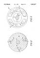
- FIG. 2is a sectional view taken along line 2--2 of FIG. 1;
- FIG. 3is a sectional view taken along line 3--3 of FIG. 1.
- the continuously variable hydrostatic transmissionaccording to the preferred embodiment of the present invention, generally indicated at 10 in FIG. 1, comprises, as basic components, a housing 12 in which are journaled an input shaft 14 and an output shaft 16 in coaxial, generally end-to-end relation.
- the end of input shaft 14 external to the housingis driving connection to a prime mover, such as a vehicular internal combustion engine (not shown), while the end of output shaft 16 external to the housing is driving connection to a load, such as vehicular driving wheels (not shown).
- Input shaft 14drives a hydraulic pump unit, generallyindicated at 18.
- a hydraulic motor unit, generally indicated at 20,is grounded to housing 12 in axially opposed relation to pump unit 18.
- a wedge-shaped swashplateis drivingly connected to the output shaft 16 in position between the pump and motor units and is apertured, as indicated at 23, to accommodate pumped exchanges of hydraulic fluid between the pump and motor units.
- a ratio controllerschematically indicated at 24, is linked to swashplate 22 for the purpose of pivotally adjusting the angle of swashplate orientation relative to the output shaft axis 25, thereby adjustably setting the transmission ratio of the input shaft speed to the output shaft speed.
- transmission 10alsoincludes a hydraulic circuit, generally indicated at 26, operative to abruptly establish a neutral transmission ratio condition of input to output shaft speeds (1:10), regardless of the current swashplate angle (transmission ratio) set by the ratio controller 24.
- the housing 12includes a cover 30, secured in place by an annular array of bolts (not shown), to close off the open input end of the housing.
- Input shaft 14extends into housing 12 through, and is journaled in a central opening in, the cover. The inner end of input shaft14 is counterbored to provide a cylindrical recess for receiving a reduced diameter inner terminal portion of output shaft 16.
- a roller bearing ring 32fitted in this input shaft recess, provides inner end journal support for the output shaft.
- the inner terminal portion of input shaft 14extendsthrough a bore 33 in a carrier 34 for a plurality of pistons including hydraulic pump unit 18.
- the input shaft and carrier boreare splined, as indicated at 35, such that the input shaft and the pump piston carrier 34 are in torque-coupled relation.
- the pump pistonsfor example, ten in number with two being generally indicated at 36, are uniformly distributed in a circle array concentric with output shaft axis 25 in the manner disclosed in the cited patent and patent applications.
- Each pump piston 36includes a piston head 38 swivel-mounted to the free end of a mounting post 40, whose other end is machined to be threaded into a tapped hole in carrier 34.
- the pump piston heads 38are slidingly received in a circle array of cylinders 42 formed in an annular cylinder block 44 surrounding output shaft 16.
- hydraulic motor unit 20is essentially structurally equivalent to hydraulic pump unit 18.
- the hydraulic motor unitis instead grounded to housing 12 by an annular array of mounting posts 50 having machined ends threaded into tapped holes in a housing block 52.
- a piston head 54is swivel mounted on the free end of each mounting post 50.
- a motor cylinder block 56provides a circular arrayof motor cylinders 58 for respectively slidingly receiving motor piston heads 54. Since motor unit 20 is grounded to housing 12 by posts 50, the motor piston and cylinder block 56 do not rotate, however, the swivel mountings of motor piston heads 54 to posts 50 accommodate nutating (precessing) motion of the motor cylinder block during transmission operation.
- output shaft 16extends rightward through the central opening in a housing block 52 closing off the output end of the transmission 10.
- Swashplate 22is drivingly connected to output shaft 16 in operative position between pump unit 18 and motor unit 20 by a transverse pin 60.
- the axis of pin 60orthogonal to the output shaft axis25, constitutes a pivot axis for swashplate 22 to accommodate transmission ratio-change adjustment of the swashplate angular orientation relative to the output shaft axis 25 by ratio controller 24.
- This controlleris illustrated schematically, since it may take a variety of form, as seen, for example, from the cited patent and patent applications.
- Swashplate 22includes an input face 62 in intimate sliding contact with face 63 of pump cylinder block 44 and an output face 64 in intimate sliding contact with face 65 of motor cylinder block 56.
- the input and output faces of swashplate 22are relatively oriented at an acute angle toprovide the wedge shape of the swashplate.
- the swashplate input and output surfacesare formed with a pair of diametrically opposed semi-annular surface cavities 70 and 72 in axial registry.
- the cavities 70,70 and 72,72are in fluid communication via swashplate ports 23.
- Pump cylinders 42are in fluid communication with thecavities 70,72 in swashplate input face 62 via respective openings 43 in pump cylinder block 44, while motor cylinders 58 are in fluid communication with the cavities 70,72 in the swashplate output face 64 viaopenings 59 in motor cylinder block 56.
- a pan 74is attached to the lower portion of housing 12 to provide a sump 76 containing hydraulic fluid 77.
- a sump pump 78disposed in the sump and typically driven off the input shaft by a drive connection (not shown), pumps makeup hydraulic fluid through a line 80 to an annular chamber 82 provided in an annular channel member 83 affixed to housing block 52.
- Three motor piston mounting posts 50at angular locations as close to 120° apart as possible, given the number of motor pistons, are provided with axial bores 51 that communicate with axial passages 84 in housing block 52 and passages 85 in channel member 83opening into chamber 82.
- One-way check valves 86are incorporated in housing block 52 to ensure that hydraulic make-up fluid can only flow in the direction of arrow 87 through these three fluid connections from chamber 82 through passages 85, 84, and 51 into the associated motor cylinders 58 through openings 55 in motor piston heads 54.
- the volumes of the cylindersare progressively expanded. This is considered to be the low pressure or suction side of the swashplate occupied by surface cavities 70.
- the associated check valve 86opens to permit the flow of make-up hydraulic fluid from chamber 82 into the associated motor cylinder 58, since the scavenge pumping fluid pressure of sump pump 70 exceeds the fluid pressure in the low pressure side of the swashplate.
- the threeaxially bored motor piston mounting postsare approximately 120° apart, at least one is always aligned with the low pressure side of the swashplate 22 to ensure that the transmission is never starved for make-uphydraulic fluid.
- check valve86close, so as to isolate the low scavenge pumping fluid pressure of the sump pump 78 from the high operating fluid pressures of the transmission existing in the high pressure side of the swashplate.
- neutral-setting hydraulic circuit 26includes three circuit branches 90 including three angularly spaced radialpassages 92 in housing block 52 whose inner ends open respectively into thethree end block axial passages 84 downstream from the check vales 86.
- Each of the circuit branches 90is connected to a common fluid line 94 through a one-way check valve 96 effective to permit hydraulic fluid flow only in the direction of arrow 97.
- Fluid line 94is connected to an inlet port 98 of a solenoid valve 100.
- the outlet port 102 of this valveis connected by a fluid line 104 back to the interior of housing 12 which is at the atmospheric pressure of sump 76.
- Solenoid valve 100includes a valve spool 106 and a plunger 108 which is acted upon by a compression spring 110 that biases the valve spool to a de-actuated position illustrated in phantom line. It is seen that, with the valve spool 106 in its phantom line de-actuated position, the valve inlet port 98 and output port 102 are unblocked, thus venting circuit branches 90 to the sump atmosphere pressure. The fluid pressures in the high and low pressure sides of swashplate 22 are then equalized at atmospheric pressure, and the hydrostatic torque components exerted on theswashplate by the hydraulic pump and motor units are reduced to essentiallyzero.
- a solenoid coil 112is wound aboutplunger 106 and connected into an electrical activating circuit including acurrent source 114 and a control module 116, which may simply be in the form of an operator-controlled switch. As long as this switch is held closed, solenoid coil 112 is energized to retract valve spool 106 to its solid line, actuated position blocking inlet port 98.
- the transmissioncannow be pressurized by the hydraulic pump and motor units to re-establish the normal operating fluid pressures in the high and low pressure sides ofswashplate 22, and then output shaft 16 is again driven at the transmissionratio set by controller 24.
- check valves 96isolate the high and low pressure sides of the swashplate exposed to the neutral-setting hydraulic circuit 26. It will be appreciated that by providing the de-actuated position of solenoid valve 100 as the neutral-setting valve position, the neutral-setting hydraulic circuit is rendered fail-safe. That is, in the event of an electrical failure, a neutral transmission ratio setting is imposed on transmission.
Landscapes
- Engineering & Computer Science (AREA)
- General Engineering & Computer Science (AREA)
- Mechanical Engineering (AREA)
- Control Of Fluid Gearings (AREA)
Abstract
Description
Claims (8)
Priority Applications (10)
| Application Number | Priority Date | Filing Date | Title |
|---|---|---|---|
| US08/543,545US5642617A (en) | 1995-10-16 | 1995-10-16 | Continuously variable hydrostatic transmission with neutral-setting hydraulic circuit |
| AU67167/96AAU6716796A (en) | 1995-10-16 | 1996-07-31 | Continuously variable hydrostatic transmission with neutral-setting hydraulic circuit |
| JP51579297AJP3886534B2 (en) | 1995-10-16 | 1996-07-31 | Continuously variable hydraulic transmission with neutral set hydraulic circuit |
| CN96198822ACN1203652A (en) | 1995-10-16 | 1996-07-31 | Continuously variable hydrostatic transmission with neutral-setting hydraulic circuit |
| PCT/US1996/012591WO1997014896A1 (en) | 1995-10-16 | 1996-07-31 | Continuously variable hydrostatic transmission with neutral-setting hydraulic circuit |
| KR1019980702739AKR100541307B1 (en) | 1995-10-16 | 1996-07-31 | Continuously variable hydrostatic transmission with neutral-setting hydraulic circuit |
| BR9611026-0ABR9611026A (en) | 1995-10-16 | 1996-07-31 | Continuously variable hydrostatic transmission with neutral regulation hydraulic circuit |
| DE69604194TDE69604194T2 (en) | 1995-10-16 | 1996-07-31 | CONTINUOUSLY HYDROSTATIC GEARBOX WITH AN IDLE SETTING HYDRAULIC CIRCUIT |
| EP96927294AEP0854988B1 (en) | 1995-10-16 | 1996-07-31 | Continuously variable hydrostatic transmission with neutral-setting hydraulic circuit |
| CA002234670ACA2234670A1 (en) | 1995-10-16 | 1996-07-31 | Continuously variable hydrostatic transmission with neutral-setting hydraulic circuit |
Applications Claiming Priority (1)
| Application Number | Priority Date | Filing Date | Title |
|---|---|---|---|
| US08/543,545US5642617A (en) | 1995-10-16 | 1995-10-16 | Continuously variable hydrostatic transmission with neutral-setting hydraulic circuit |
Publications (1)
| Publication Number | Publication Date |
|---|---|
| US5642617Atrue US5642617A (en) | 1997-07-01 |
Family
ID=24168486
Family Applications (1)
| Application Number | Title | Priority Date | Filing Date |
|---|---|---|---|
| US08/543,545Expired - LifetimeUS5642617A (en) | 1995-10-16 | 1995-10-16 | Continuously variable hydrostatic transmission with neutral-setting hydraulic circuit |
Country Status (10)
| Country | Link |
|---|---|
| US (1) | US5642617A (en) |
| EP (1) | EP0854988B1 (en) |
| JP (1) | JP3886534B2 (en) |
| KR (1) | KR100541307B1 (en) |
| CN (1) | CN1203652A (en) |
| AU (1) | AU6716796A (en) |
| BR (1) | BR9611026A (en) |
| CA (1) | CA2234670A1 (en) |
| DE (1) | DE69604194T2 (en) |
| WO (1) | WO1997014896A1 (en) |
Cited By (13)
| Publication number | Priority date | Publication date | Assignee | Title |
|---|---|---|---|---|
| WO1997044596A1 (en) | 1996-05-24 | 1997-11-27 | General Dynamics Defense Systems, Inc. | Multi-range, hydromechanical transmission for off-road vehicles |
| US5896745A (en)* | 1997-04-29 | 1999-04-27 | General Dynamics Defense Systems, Inc. | Swashplate assemblies for infinitely variable hydrostatic transmissions |
| US6068617A (en)* | 1992-12-28 | 2000-05-30 | Richmond; Frank M. | Needleless valve for use in intravenous infusion |
| US6381529B1 (en)* | 2001-06-07 | 2002-04-30 | Deere & Company | Control system for hydrostatic transmission |
| WO2003035425A1 (en)* | 2001-10-22 | 2003-05-01 | Biomet-Ross, Inc. | Lift truck drive train |
| US6595886B1 (en)* | 1999-11-30 | 2003-07-22 | Linde Aktiengesellschaft | Hydrostatic axial piston machine with a swashplate construction |
| US20040074691A1 (en)* | 2000-12-11 | 2004-04-22 | Joel Bombardier | Virtual braking system for hydrostatically driven vehicle |
| US20090274564A1 (en)* | 2008-04-30 | 2009-11-05 | Caterpillar Inc. | Floating cup pump having swashplate mounted cup elements |
| US20100043416A1 (en)* | 2008-08-21 | 2010-02-25 | Willis Jerry F | Wobble plate motor |
| WO2009106840A3 (en)* | 2008-02-29 | 2010-03-04 | Isentropic Limited | Apparatus for converting between rotational and linear movement |
| US20100107626A1 (en)* | 2008-10-31 | 2010-05-06 | Caterpillar Inc. | Hydraulic variator with adjustable drum plates |
| US20140366669A1 (en)* | 2013-06-13 | 2014-12-18 | David J. Goerend | Transmission plate |
| US9551223B2 (en) | 2009-08-19 | 2017-01-24 | Jerry F. Willis | Fluid stream driven wobble plate motor |
Families Citing this family (2)
| Publication number | Priority date | Publication date | Assignee | Title |
|---|---|---|---|---|
| US5931758A (en) | 1998-04-08 | 1999-08-03 | General Dynamics Land Systems, Inc. | Simplified multi-range hydromechanical transmission for vehicles |
| US12372076B2 (en)* | 2022-08-25 | 2025-07-29 | University Of Manitoba | Variable split displacement ratio axial piston machines |
Citations (7)
| Publication number | Priority date | Publication date | Assignee | Title |
|---|---|---|---|---|
| US3131540A (en)* | 1961-04-20 | 1964-05-05 | Kopat Ges Fur Konstruktion Ent | Hydrostatic drive, particularly for automotive vehicles |
| US3906727A (en)* | 1973-09-26 | 1975-09-23 | Melvin Corp | Hydrostatic drive with direction memory |
| US5486142A (en)* | 1994-11-21 | 1996-01-23 | Martin Marietta Corporation | Hydrostatic transmission including a simplified ratio controller |
| US5493862A (en)* | 1994-11-03 | 1996-02-27 | Martin Marietta Corporation | Continuously variable hydrostatic transmission |
| US5524437A (en)* | 1995-01-30 | 1996-06-11 | Martin Marietta Corporation | Continuously variable hydrostatic transmission having ratio controller actuating components incorporated in output shaft |
| US5531072A (en)* | 1995-03-31 | 1996-07-02 | Martin Marietta Corporation | Continuously variable hydrostatic transmission having swashplate-mounted cylinder blocks |
| US5540048A (en)* | 1995-01-30 | 1996-07-30 | Martin Marietta Corporation | Continuously variable hydrostatic transmission including a pulse width modulation ratio controller |
Family Cites Families (4)
| Publication number | Priority date | Publication date | Assignee | Title |
|---|---|---|---|---|
| US3698189A (en)* | 1971-04-09 | 1972-10-17 | Cessna Aircraft Co | Neutral control for hydraulic transmission |
| JPH086801B2 (en)* | 1987-11-09 | 1996-01-29 | 本田技研工業株式会社 | Distribution ring for hydraulic continuously variable transmission |
| JPH0289867A (en)* | 1988-09-28 | 1990-03-29 | Honda Motor Co Ltd | Hydraulic continuously variable transmission |
| EP0567598B1 (en)* | 1991-01-14 | 1998-03-11 | Advanced Power Technology, Inc. | Hydraulic machine |
- 1995
- 1995-10-16USUS08/543,545patent/US5642617A/ennot_activeExpired - Lifetime
- 1996
- 1996-07-31WOPCT/US1996/012591patent/WO1997014896A1/enactiveIP Right Grant
- 1996-07-31CNCN96198822Apatent/CN1203652A/enactivePending
- 1996-07-31AUAU67167/96Apatent/AU6716796A/ennot_activeAbandoned
- 1996-07-31DEDE69604194Tpatent/DE69604194T2/ennot_activeExpired - Lifetime
- 1996-07-31CACA002234670Apatent/CA2234670A1/ennot_activeAbandoned
- 1996-07-31KRKR1019980702739Apatent/KR100541307B1/ennot_activeExpired - Fee Related
- 1996-07-31BRBR9611026-0Apatent/BR9611026A/ennot_activeApplication Discontinuation
- 1996-07-31EPEP96927294Apatent/EP0854988B1/ennot_activeExpired - Lifetime
- 1996-07-31JPJP51579297Apatent/JP3886534B2/ennot_activeExpired - Fee Related
Patent Citations (7)
| Publication number | Priority date | Publication date | Assignee | Title |
|---|---|---|---|---|
| US3131540A (en)* | 1961-04-20 | 1964-05-05 | Kopat Ges Fur Konstruktion Ent | Hydrostatic drive, particularly for automotive vehicles |
| US3906727A (en)* | 1973-09-26 | 1975-09-23 | Melvin Corp | Hydrostatic drive with direction memory |
| US5493862A (en)* | 1994-11-03 | 1996-02-27 | Martin Marietta Corporation | Continuously variable hydrostatic transmission |
| US5486142A (en)* | 1994-11-21 | 1996-01-23 | Martin Marietta Corporation | Hydrostatic transmission including a simplified ratio controller |
| US5524437A (en)* | 1995-01-30 | 1996-06-11 | Martin Marietta Corporation | Continuously variable hydrostatic transmission having ratio controller actuating components incorporated in output shaft |
| US5540048A (en)* | 1995-01-30 | 1996-07-30 | Martin Marietta Corporation | Continuously variable hydrostatic transmission including a pulse width modulation ratio controller |
| US5531072A (en)* | 1995-03-31 | 1996-07-02 | Martin Marietta Corporation | Continuously variable hydrostatic transmission having swashplate-mounted cylinder blocks |
Cited By (15)
| Publication number | Priority date | Publication date | Assignee | Title |
|---|---|---|---|---|
| US6068617A (en)* | 1992-12-28 | 2000-05-30 | Richmond; Frank M. | Needleless valve for use in intravenous infusion |
| WO1997044596A1 (en) | 1996-05-24 | 1997-11-27 | General Dynamics Defense Systems, Inc. | Multi-range, hydromechanical transmission for off-road vehicles |
| US5896745A (en)* | 1997-04-29 | 1999-04-27 | General Dynamics Defense Systems, Inc. | Swashplate assemblies for infinitely variable hydrostatic transmissions |
| US6595886B1 (en)* | 1999-11-30 | 2003-07-22 | Linde Aktiengesellschaft | Hydrostatic axial piston machine with a swashplate construction |
| US20040074691A1 (en)* | 2000-12-11 | 2004-04-22 | Joel Bombardier | Virtual braking system for hydrostatically driven vehicle |
| US6381529B1 (en)* | 2001-06-07 | 2002-04-30 | Deere & Company | Control system for hydrostatic transmission |
| US6604601B2 (en)* | 2001-10-22 | 2003-08-12 | Biomet-Ross, Inc. | Lift truck drive train |
| WO2003035425A1 (en)* | 2001-10-22 | 2003-05-01 | Biomet-Ross, Inc. | Lift truck drive train |
| WO2009106840A3 (en)* | 2008-02-29 | 2010-03-04 | Isentropic Limited | Apparatus for converting between rotational and linear movement |
| US20090274564A1 (en)* | 2008-04-30 | 2009-11-05 | Caterpillar Inc. | Floating cup pump having swashplate mounted cup elements |
| US20100043416A1 (en)* | 2008-08-21 | 2010-02-25 | Willis Jerry F | Wobble plate motor |
| US8545176B2 (en) | 2008-08-21 | 2013-10-01 | Jerry F. Willis | Wobble plate motor |
| US20100107626A1 (en)* | 2008-10-31 | 2010-05-06 | Caterpillar Inc. | Hydraulic variator with adjustable drum plates |
| US9551223B2 (en) | 2009-08-19 | 2017-01-24 | Jerry F. Willis | Fluid stream driven wobble plate motor |
| US20140366669A1 (en)* | 2013-06-13 | 2014-12-18 | David J. Goerend | Transmission plate |
Also Published As
| Publication number | Publication date |
|---|---|
| CN1203652A (en) | 1998-12-30 |
| EP0854988A1 (en) | 1998-07-29 |
| BR9611026A (en) | 1999-12-28 |
| KR100541307B1 (en) | 2006-08-30 |
| DE69604194D1 (en) | 1999-10-14 |
| CA2234670A1 (en) | 1997-04-24 |
| EP0854988B1 (en) | 1999-09-08 |
| DE69604194T2 (en) | 2000-03-23 |
| AU6716796A (en) | 1997-05-07 |
| KR19990064251A (en) | 1999-07-26 |
| JPH11513780A (en) | 1999-11-24 |
| JP3886534B2 (en) | 2007-02-28 |
| WO1997014896A1 (en) | 1997-04-24 |
Similar Documents
| Publication | Publication Date | Title |
|---|---|---|
| US5642617A (en) | Continuously variable hydrostatic transmission with neutral-setting hydraulic circuit | |
| EP0763171B1 (en) | Continuously variable hydrostatic transmission | |
| EP0736152B1 (en) | Continuously variable hydrostatic transmission | |
| EP0739462B1 (en) | Ratio controller for a hydrostatic transmission | |
| US5524437A (en) | Continuously variable hydrostatic transmission having ratio controller actuating components incorporated in output shaft | |
| EP0977956B1 (en) | Continuously variable hydrostatic transmission including 1:1 ratio lock-up clutch | |
| CA2348197C (en) | Hydrostatic continuously variable transmission | |
| EP0753113B1 (en) | Improved ratio controller for continuously variable hydrostatic transmission | |
| MXPA98002952A (en) | Continuously variable hydrostatic transmission with neu fixing hydraulic circuit |
Legal Events
| Date | Code | Title | Description |
|---|---|---|---|
| AS | Assignment | Owner name:MARTIN MARIETTA CORPORATION, MARYLAND Free format text:ASSIGNMENT OF ASSIGNORS INTEREST;ASSIGNORS:LARKIN, ROBERT F.;PURCELL, DONALD M.;REEL/FRAME:007767/0798 Effective date:19951012 | |
| FEPP | Fee payment procedure | Free format text:PAYOR NUMBER ASSIGNED (ORIGINAL EVENT CODE: ASPN); ENTITY STATUS OF PATENT OWNER: LARGE ENTITY | |
| STCF | Information on status: patent grant | Free format text:PATENTED CASE | |
| AS | Assignment | Owner name:GENERAL DYNAMICS DEFENSE SYSTEMS, INC., VIRGINIA Free format text:ASSIGNMENT OF ASSIGNORS INTEREST;ASSIGNOR:LOCKHEED MARTIN CORPORATION;REEL/FRAME:009012/0340 Effective date:19970202 | |
| AS | Assignment | Owner name:GENERAL DYNAMICS LAND SYSTEMS, INC., MICHIGAN Free format text:ASSIGNMENT OF ASSIGNORS INTEREST;ASSIGNOR:GENERAL DYNAMICS DEFENSE SYSTEMS, INC.;REEL/FRAME:010272/0170 Effective date:19990927 | |
| FPAY | Fee payment | Year of fee payment:4 | |
| FPAY | Fee payment | Year of fee payment:8 | |
| AS | Assignment | Owner name:L-3 COMMUNICATIONS CORPORATION, NEW YORK Free format text:ASSIGNMENT OF ASSIGNORS INTEREST;ASSIGNOR:GENERAL DYNAMICS LAND SYSTEMS INC.;REEL/FRAME:016996/0078 Effective date:20050225 | |
| FPAY | Fee payment | Year of fee payment:12 | |
| REMI | Maintenance fee reminder mailed |