US5642469A - Direct-drive manipulator for pen-based force display - Google Patents
Direct-drive manipulator for pen-based force displayDownload PDFInfo
- Publication number
- US5642469A US5642469AUS08/334,621US33462194AUS5642469AUS 5642469 AUS5642469 AUS 5642469AUS 33462194 AUS33462194 AUS 33462194AUS 5642469 AUS5642469 AUS 5642469A
- Authority
- US
- United States
- Prior art keywords
- control point
- actuator
- coupled
- joint
- end effector
- Prior art date
- Legal status (The legal status is an assumption and is not a legal conclusion. Google has not performed a legal analysis and makes no representation as to the accuracy of the status listed.)
- Ceased
Links
Images


Classifications
- G—PHYSICS
- G06—COMPUTING OR CALCULATING; COUNTING
- G06F—ELECTRIC DIGITAL DATA PROCESSING
- G06F3/00—Input arrangements for transferring data to be processed into a form capable of being handled by the computer; Output arrangements for transferring data from processing unit to output unit, e.g. interface arrangements
- G06F3/01—Input arrangements or combined input and output arrangements for interaction between user and computer
- G06F3/016—Input arrangements with force or tactile feedback as computer generated output to the user
- B—PERFORMING OPERATIONS; TRANSPORTING
- B25—HAND TOOLS; PORTABLE POWER-DRIVEN TOOLS; MANIPULATORS
- B25J—MANIPULATORS; CHAMBERS PROVIDED WITH MANIPULATION DEVICES
- B25J13/00—Controls for manipulators
- B25J13/02—Hand grip control means
- B—PERFORMING OPERATIONS; TRANSPORTING
- B25—HAND TOOLS; PORTABLE POWER-DRIVEN TOOLS; MANIPULATORS
- B25J—MANIPULATORS; CHAMBERS PROVIDED WITH MANIPULATION DEVICES
- B25J13/00—Controls for manipulators
- B25J13/08—Controls for manipulators by means of sensing devices, e.g. viewing or touching devices
- B25J13/085—Force or torque sensors
- B—PERFORMING OPERATIONS; TRANSPORTING
- B25—HAND TOOLS; PORTABLE POWER-DRIVEN TOOLS; MANIPULATORS
- B25J—MANIPULATORS; CHAMBERS PROVIDED WITH MANIPULATION DEVICES
- B25J9/00—Programme-controlled manipulators
- B25J9/10—Programme-controlled manipulators characterised by positioning means for manipulator elements
- B25J9/106—Programme-controlled manipulators characterised by positioning means for manipulator elements with articulated links
- G—PHYSICS
- G06—COMPUTING OR CALCULATING; COUNTING
- G06F—ELECTRIC DIGITAL DATA PROCESSING
- G06F3/00—Input arrangements for transferring data to be processed into a form capable of being handled by the computer; Output arrangements for transferring data from processing unit to output unit, e.g. interface arrangements
- G06F3/01—Input arrangements or combined input and output arrangements for interaction between user and computer
- G06F3/03—Arrangements for converting the position or the displacement of a member into a coded form
- G06F3/033—Pointing devices displaced or positioned by the user, e.g. mice, trackballs, pens or joysticks; Accessories therefor
- G06F3/0346—Pointing devices displaced or positioned by the user, e.g. mice, trackballs, pens or joysticks; Accessories therefor with detection of the device orientation or free movement in a 3D space, e.g. 3D mice, 6-DOF [six degrees of freedom] pointers using gyroscopes, accelerometers or tilt-sensors
- G—PHYSICS
- G09—EDUCATION; CRYPTOGRAPHY; DISPLAY; ADVERTISING; SEALS
- G09B—EDUCATIONAL OR DEMONSTRATION APPLIANCES; APPLIANCES FOR TEACHING, OR COMMUNICATING WITH, THE BLIND, DEAF OR MUTE; MODELS; PLANETARIA; GLOBES; MAPS; DIAGRAMS
- G09B23/00—Models for scientific, medical, or mathematical purposes, e.g. full-sized devices for demonstration purposes
- G09B23/28—Models for scientific, medical, or mathematical purposes, e.g. full-sized devices for demonstration purposes for medicine
- G—PHYSICS
- G06—COMPUTING OR CALCULATING; COUNTING
- G06F—ELECTRIC DIGITAL DATA PROCESSING
- G06F2203/00—Indexing scheme relating to G06F3/00 - G06F3/048
- G06F2203/01—Indexing scheme relating to G06F3/01
- G06F2203/015—Force feedback applied to a joystick
Definitions
- This inventionrelates to direct-drive manipulators and force feedback devices. More particularly this invention relates to a direct-drive manipulator having three degrees of freedom and suitable for use as a pen-based force display for a virtual reality or telerobotic environment.
- a manipulatorcan serve as an input device for controlling movement of a robot or other real or simulated device.
- a direct drive manipulatorresponds to operator manipulations using one or more actuators directly coupled to a load (on the output side) or an operator contact point (on the input side). This contrasts with an indirectly driven manipulator which responds to operator manipulations using one or more actuators indirectly coupled to the load or operator contact point through gears or other scaling devices.
- a pen-based manipulatoris characterized by an elongated member having a contact point for applying operator input forces and displacements.
- the manipulatorenables an operator holding the elongated member to move the member within a workspace under the control of manipulator components (e.g., actuators, joints and links).
- a force feedback deviceis characterized as an output device in which forces are applied to an operator holding the feedback device.
- a master manipulator located away from a robotcontrols a slave manipulator located at the robot.
- the master manipulatorserves as an input device for commanding movement of the robot via forces or displacements applied to the manipulator by an operator.
- the master manipulatorsometimes serves as a force feedback device for exhibiting force sensations felt by the operator.
- a force reflection applicationfor example, the forces encountered by the robot under control are reflected back to the operator at the manipulator to enable improved coordination of robot motion and dexterity.
- 5,072,361discloses a force-reflective tele-operation control system in which a master station includes an actuator exhibiting force resistance to movement in a master link. Such resistance is to be comparable to the resistance encountered by a slave device so that movement of the master device by an operator tracks movement of the slave device being controlled.
- a force feedback devicealso is referred to as a force display.
- displayrefers to a visual output device upon which ephemeral images are shown.
- the displayserves as a visual interface between an end user and a computer environment. An operator uses his visual sense to experience the images.
- force displayis coined to refer to an output device upon which ephemeral forces are exhibited.
- the force displayserves as a force-reflective, haptic, kinaesthetic, or tactile interface between an operator and a real or simulated environment. The operator uses his sense of touch to experience the forces.
- the force displaytypically is more than a display in that it also serves as an input device.
- a force displayis a bidirectional mechanical interface through which an operator both applies and receives forces and displacements.
- a direct-drive manipulatorenables precision manipulation and force display at a control point.
- an operatorapplies forces to the control point.
- the manipulatorresponds to the applied forces allowing movement of the control point within a workspace domain over three degrees of freedom.
- force sensationsare reflected back to the control point to be experienced by the operator.
- Virtual reality, telerobotic, and other simulated, real or remote applicationscan be created to define a control algorithm.
- a control algorithmmay define immovable object shapes. An operator then is able to trace the virtual object shapes and feel the object boundaries.
- a control algorithmmay define tissue having shape, texture and force resistance variables at different locations. An operator then may perform a virtual reality surgery, in which the control point is the cutting point of a scalpel. Depending on the position of the control point and force applied, the operator experiences the sensation of cutting through the virtual tissue.
- the control algorithmis defined as a reflection of forces encountered by the robot.
- This inventionis directed toward the manipulator with control point to be used as a force display.
- the manipulatorTo serve as a force display it is desirable that the manipulator have substantially no backlash, very low friction, and very low inertia. Backlash, friction and inertia detract from a natural feel of a control point. No matter how sophisticated a control algorithm, if the manipulator suffers from significant amounts of backlash, friction or inertia, then its use as a force display is compromised. It also is desirable that the manipulator have a high bandwidth so that high frequency force components can be displayed.
- direct drive actuatorsare used for the manipulator.
- Direct drive actuatorshave force display advantages over indirect drive actuators.
- Indirect drive geared actuatorshave unacceptable backlash and friction characteristics.
- indirect drive actuatorstypically have lower bandwidth capability.
- Direct drive actuatorsare implemented here in a configuration for a control point having no backlash, very low friction and very high force generation bandwidth.
- a parallel actuator structureis used to control motion in a horizontal plane to achieve very low inertia of the control point.
- the parallel structureprovides two degrees of freedom in a horizontal plane of motion.
- the parallel structureis a redundant structure including three chains in parallel coupled at the control point.
- Each chainincludes an actuator and two links.
- Each actuatoris positioned at a fixed origin.
- One end of an inner linkis coupled to the actuator.
- An opposite end of the inner linkis coupled to one end of an outer link.
- a jointis formed at the connection of the inner and outer links.
- the opposite end of the outer linkis coupled to the control point.
- the three chainsdefine a planar structure in which three actuators provide two degrees of freedom with redundancy.
- the parallel redundant (3-chain) structure of this inventionimproves over prior parallel 2-chain structures by enabling a more uniform force capability throughout the manipulator workspace.
- the maximum force that can be applied to a control pointvaries depending on where the control point currently is positioned.
- the maximum force that can be appliedis substantially uniform throughout the workspace.
- redundant sensingalso is performed by including a sensor at each actuator in the parallel structure. Redundant sensing enables more uniform high resolution position sensing throughout the workspace.
- the end-effectordefines an open tool interface point as the control point.
- An operatorholds his finger, a pen-like tool or other tool to the interface point and applies forces or displacements to manipulate the control point.
- the operatorcan apply or remove the tool from the control point with a natural feel.
- the toolis a scalpel in a surgical virtual reality application
- the trainee physiciancan manipulate the scalpel as during a real operation, then apply the scalpel to the control point to perform a cutting/surgical maneuver. The operator therefore achieves a more realistic making and breaking of contact.
- a pair of rotational actuatorsrotate the parallel structure about an axis to approximate a linear motion along a third axis, and provide a third degree of freedom for the control point.
- manipulator of this inventionhas substantially no backlash, very low friction, very low inertia and a very high force generation bandwidth enabling a natural feel when implemented as a force display.
- Another advantageis that embodiments have a substantially uniform force capability throughout there workspace.
- FIG. 1is a schematic diagram of the pen-based direct-drive manipulator according to an embodiment of this invention
- FIG. 2is a diagram of the control point and workspace for the manipulator of FIG. 1 with a pen-like tool used by an operator;
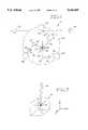
- FIG. 3is a perspective view of the pen-based direct-drive manipulator according to an embodiment of this invention.
- FIG. 4is a perspective view of the planar assembly portion of the manipulator of FIG. 1 which defines two degrees of freedom;
- FIG. 5is another perspective view of the planar assembly portion of the manipulator of FIG. 1 which defines two degrees of freedom;
- FIG. 1shows a schematic diagram of the pen-based direct-drive manipulator 10 according to one embodiment of the invention.
- the function of the manipulator 10is to enable precision manipulation and force display at a control point 12.
- an operatoruses a pen-like or other tool 14 to apply forces/displacements to the control point 12.
- the manipulator 10responds to the applied forces allowing control point 12 movement with three degrees of freedom within a workspace 16.
- the control point 12is defined at an end-effector 18.
- the manipulator 10includes a planar structure 20 enabling motion in an xy plane to define two degrees of freedom.
- the planar structure 20is moved along a z-axis by actuators 22, 24 to define a third degree of freedom.
- FIG. 3shows an assembled direct-drive manipulator 10 according to an embodiment of this invention.
- the manipulatorincludes a planar assembly 20 mounted to rotational actuation assemblies 60, 62.
- the rotational actuation assemblies 60, 62are mounted to a yoke plate 64.
- the yoke plateis adjustably mounted to a base plate 66 via links 68, 70.
- the base plate 66rests on a surface.
- the yoke plate 64is adjustable relative to the base plate 66 to provide a desirable position and orientation to the planar assembly 20.
- an operatormay prefer the xy plane to a have a specific position and orientation relative to the operator's tool 14.
- By adjusting the yoke plate relative to the base 66a desired orientation is achieved.
- the rotational actuation assemblies 60, 62are replaced with vertical actuation assemblies. As implemented in the embodiment shown, the rotational assemblies generate motion approximating vertical motion along the z-axis of workspace 16.
- the planar structure 20is a parallel, redundant actuator assembly, including three chains 26, 28, 30 in parallel coupled at an end effector 18.
- Each chainincludes an actuator and two links.
- a first chain 26includes an actuator 32, inner link 34 and outer link 36.
- a joint 37is formed between the inner link 34 and outer link 36.
- a second chain 28includes an actuator 38, inner link 40 and outer link 42.
- a joint 43is formed between the inner link 40 and outer link 42.
- a third chain 30includes an actuator 44, inner link 46 and outer link 48.
- a joint 50is formed between the inner link 46 and outer link 48.
- Low friction ball bearings, washers and rigid connecting axesare included at joints 37, 43 and 50 and where outer links 36, 42, 48 couple to the end effector 18.
- Each actuator 32, 38, 44is fixed relative to the planar structure 20, and thus, relative to the xy plane.
- each actuator 32, 38, 44is a direct drive actuator like those used in computer hard disk drives, such as a 1.8 inch hard disk drive.
- Each actuator 32, 38, 44 structureis implemented as a direct drive actuator and includes a flat coil, magnet, encoder, encoder base, codewheel, codewheel screw and codewheel base. Encoder bases 86, 88, 90 are shown.
- the planar structure 20includes redundant actuators (e.g., 3), but not redundant encoders, (e.g., only two are used).
- the codewheelsare Hewlett Packard codewheel part no. HEDM-5120-J03 and the encoders are Hewlett Packard encoder module part no. HEDS-9100-J00.
- the magnets and flat coilsare from a 1.8 inch hard disk drive and the magnet frames 80, 82, 84 are machined from a 1.8 inch hard disk drive frame. Although 3.5 inch and 1.8 inch hard disk drive scaling is used on the described embodiment, the components may be scaled to larger or smaller dimension to increase or decrease the workspace 16 (see FIG. 2). In addition other types of actuators may be used. Preferably the actuators have low friction, low inertia and substantially no backlash.
- the planar structure 20is coupled to the rotational actuation structures 60, 62 at fixed links 90, 92.
- the links 90, 92are mounted to respect rotational actuator frames 94, 96.
- the frames 94, 96are moved by 5.25 inch hard disk drive flat coil and magnet assemblies which serve as actuators 22, 24.
- Magnets 98, 100 and flat coils 102, 104are shown.
- An encoder moduleis formed by encoder module base 106, encoder 108, codewheel 110, codewheel screw 112, codewheel base 114 and washers.
- the codewheelis a Hewlett Packard codewheel part no.
- the componentsmay be scaled to larger or smaller dimension to increase or decrease the workspace 16 (see FIG. 2).
- the rotational actuation structures 60, 62define motion approximating vertical motion along the z axis of the workspace domain. If the vertical dimension of the workspace is desired to be increased outside the range of the vertical approximation, then the motion in the z direction is coupled to the motion in the x and y directions. In the preferred embodiment such motions are substantially decoupled.
- the manipulator 10enables movement of a control point 12 within a workspace 16 over three degrees of freedom.
- Two degrees of freedomare provided by the planar actuation structure 20 allowing motion within an xy plane.
- a third degree of freedomis provided by the rotational actuation structures 60, 62 allowing motion along a z-axis.
- the workspace of the described embodimentis approximately 2 cm ⁇ 2 cm ⁇ 2 cm.
- the planar xy motion and the vertical z motionare substantially decoupled allowing for simpler kinematic modelling and simpler control algorithms.
- i ⁇ 12i ⁇ 1 + i ⁇ 2
- i x o , i y oposition of origin of i-th serial chain in xy plane
- i x in , i y inposition of intermediate joint in i-th serial chain in xy plane
- manipulator parametersare implemented:
- the joint angles, i ⁇ 1are defined as:
- the torque vector for the third degree of freedomis given as:
- F ijis the force exerted by the i-th serial chain on the j-th serial chain. Because the force are endogenous, they sum to zero:
- ⁇ zis the angular rotation of the ⁇ z joint.
- ⁇ iis the torque magnitude of the i-th actuator in the planar structure 20.
- a given controllerimplements a simplex algorithm to identify max (
- Step 1Calculate J -T e (x e (t o ));
- Step 2Calculate ⁇ 1 , ⁇ 2 , ⁇ 3 , where
- Step 4Calculate ⁇ i1 , ⁇ i2 , where
- Step 6Calculate ⁇ i3 ;
- Step 7If
- the output solutionis ⁇ i1 , ⁇ i2 , ⁇ i3 .
- a manipulator 10includes actuation structures machined in part from computer hard disk drive actuators. Characteristically these actuators have low inertia and low friction. Using 1.8" actuators for the planar actuation structure 20 and 5.25" actuators for the rotational actuating structures 60, 62, the following parameters were measured:
- the mass of each outer link 36, 42, 48is approximately 0.5 grams.
- the mass of the end effectoris less than one gram.
- the total mass of the planar actuating structure 20is approximately 150 grams.
- Peak force applied by end effector in upward directionis 13.50N.
- Peak force applied by end effector in xy planeis 1.5N.
- Maximum continuous force applied by end effector in xy planeis approximately 0.55N and substantially uniform throughout the workspace.
- the practical range of maximum force applied in xy planeis 0.5-1.5N using a simplex algorithm.
- the simplex algorithmis executed at 10 kHz as part of a controller written in assembly and C language on a 486DX 66 MHz general purpose microcomputer.
- the manipulator 10 implemented as a force displayis driven in one embodiment by a controller program executed on a general purpose microcomputer.
- the controller programdefines a virtual reality environment or reflects a tele-environment.
- An operator using his finger, pen-like tool or other deviceapplies forces to the control point 12 moving the control point 12 within the end effector workspace 16.
- the planar actuating structureresponds to allow movement of the end effector 14.
- the rotational actuating structuresrespond to allow common movement of the end effector 14 and planar structure 20 along the z-axis.
Landscapes
- Engineering & Computer Science (AREA)
- General Engineering & Computer Science (AREA)
- Theoretical Computer Science (AREA)
- Physics & Mathematics (AREA)
- General Physics & Mathematics (AREA)
- Human Computer Interaction (AREA)
- Robotics (AREA)
- Mechanical Engineering (AREA)
- Algebra (AREA)
- Mathematical Physics (AREA)
- Medical Informatics (AREA)
- Computational Mathematics (AREA)
- General Health & Medical Sciences (AREA)
- Mathematical Analysis (AREA)
- Mathematical Optimization (AREA)
- Medicinal Chemistry (AREA)
- Pure & Applied Mathematics (AREA)
- Business, Economics & Management (AREA)
- Educational Administration (AREA)
- Educational Technology (AREA)
- Chemical & Material Sciences (AREA)
- Health & Medical Sciences (AREA)
- Manipulator (AREA)
Abstract
Description
This invention was made with government support under grant number BCS 9058408 awarded by the National Science Foundation. The government has certain rights in the invention.
This invention relates to direct-drive manipulators and force feedback devices. More particularly this invention relates to a direct-drive manipulator having three degrees of freedom and suitable for use as a pen-based force display for a virtual reality or telerobotic environment.
A manipulator can serve as an input device for controlling movement of a robot or other real or simulated device. A direct drive manipulator responds to operator manipulations using one or more actuators directly coupled to a load (on the output side) or an operator contact point (on the input side). This contrasts with an indirectly driven manipulator which responds to operator manipulations using one or more actuators indirectly coupled to the load or operator contact point through gears or other scaling devices.
A pen-based manipulator is characterized by an elongated member having a contact point for applying operator input forces and displacements. The manipulator enables an operator holding the elongated member to move the member within a workspace under the control of manipulator components (e.g., actuators, joints and links).
A force feedback device is characterized as an output device in which forces are applied to an operator holding the feedback device. In several telerobotic applications, for example, a master manipulator located away from a robot controls a slave manipulator located at the robot. The master manipulator serves as an input device for commanding movement of the robot via forces or displacements applied to the manipulator by an operator. In addition, the master manipulator sometimes serves as a force feedback device for exhibiting force sensations felt by the operator. In a force reflection application, for example, the forces encountered by the robot under control are reflected back to the operator at the manipulator to enable improved coordination of robot motion and dexterity. U.S. Pat. No. 5,072,361 (Davis et al.) discloses a force-reflective tele-operation control system in which a master station includes an actuator exhibiting force resistance to movement in a master link. Such resistance is to be comparable to the resistance encountered by a slave device so that movement of the master device by an operator tracks movement of the slave device being controlled.
A force feedback device also is referred to as a force display. In the computer field the term display refers to a visual output device upon which ephemeral images are shown. The display serves as a visual interface between an end user and a computer environment. An operator uses his visual sense to experience the images. Analogously, the term "force display" is coined to refer to an output device upon which ephemeral forces are exhibited. The force display serves as a force-reflective, haptic, kinaesthetic, or tactile interface between an operator and a real or simulated environment. The operator uses his sense of touch to experience the forces. The force display, however, typically is more than a display in that it also serves as an input device. A force display is a bidirectional mechanical interface through which an operator both applies and receives forces and displacements.
According to the invention, a direct-drive manipulator enables precision manipulation and force display at a control point. By using a pen-like or other end-effector an operator applies forces to the control point. The manipulator responds to the applied forces allowing movement of the control point within a workspace domain over three degrees of freedom. When combined with a controller implementing a control algorithm for a specific application environment, force sensations are reflected back to the control point to be experienced by the operator. Virtual reality, telerobotic, and other simulated, real or remote applications can be created to define a control algorithm. For example, a control algorithm may define immovable object shapes. An operator then is able to trace the virtual object shapes and feel the object boundaries. In another example, a control algorithm may define tissue having shape, texture and force resistance variables at different locations. An operator then may perform a virtual reality surgery, in which the control point is the cutting point of a scalpel. Depending on the position of the control point and force applied, the operator experiences the sensation of cutting through the virtual tissue. In a telerobotic application for remotely controlling a robot, the control algorithm is defined as a reflection of forces encountered by the robot. There are many other examples of a control algorithm that could be created to use with the manipulator. This invention is directed toward the manipulator with control point to be used as a force display.
To serve as a force display it is desirable that the manipulator have substantially no backlash, very low friction, and very low inertia. Backlash, friction and inertia detract from a natural feel of a control point. No matter how sophisticated a control algorithm, if the manipulator suffers from significant amounts of backlash, friction or inertia, then its use as a force display is compromised. It also is desirable that the manipulator have a high bandwidth so that high frequency force components can be displayed.
According to one aspect of the invention, direct drive actuators are used for the manipulator. Direct drive actuators have force display advantages over indirect drive actuators. Indirect drive geared actuators have unacceptable backlash and friction characteristics. Also, indirect drive actuators typically have lower bandwidth capability. Direct drive actuators are implemented here in a configuration for a control point having no backlash, very low friction and very high force generation bandwidth.
According to another aspect of the invention, a parallel actuator structure is used to control motion in a horizontal plane to achieve very low inertia of the control point. The parallel structure provides two degrees of freedom in a horizontal plane of motion.
According to another aspect of the invention, the parallel structure is a redundant structure including three chains in parallel coupled at the control point. Each chain includes an actuator and two links. Each actuator is positioned at a fixed origin. One end of an inner link is coupled to the actuator. An opposite end of the inner link is coupled to one end of an outer link. A joint is formed at the connection of the inner and outer links. The opposite end of the outer link is coupled to the control point. The three chains define a planar structure in which three actuators provide two degrees of freedom with redundancy.
The parallel redundant (3-chain) structure of this invention improves over prior parallel 2-chain structures by enabling a more uniform force capability throughout the manipulator workspace. In the workspace of a conventional 2-chain structure the maximum force that can be applied to a control point varies depending on where the control point currently is positioned. According to the 3-chain structure of this invention, however, the maximum force that can be applied is substantially uniform throughout the workspace.
According to another aspect of the invention redundant sensing also is performed by including a sensor at each actuator in the parallel structure. Redundant sensing enables more uniform high resolution position sensing throughout the workspace.
According to another aspect of the invention the end-effector defines an open tool interface point as the control point. An operator holds his finger, a pen-like tool or other tool to the interface point and applies forces or displacements to manipulate the control point. By providing an open interface there is no friction or backlash introduces by a device that would hold the tool tip in place at the control point. Similarly the operator can apply or remove the tool from the control point with a natural feel. For example if the tool is a scalpel in a surgical virtual reality application, the trainee physician can manipulate the scalpel as during a real operation, then apply the scalpel to the control point to perform a cutting/surgical maneuver. The operator therefore achieves a more realistic making and breaking of contact.
According to another aspect of the invention, a pair of rotational actuators rotate the parallel structure about an axis to approximate a linear motion along a third axis, and provide a third degree of freedom for the control point.
One advantage of the manipulator of this invention is that embodiments have substantially no backlash, very low friction, very low inertia and a very high force generation bandwidth enabling a natural feel when implemented as a force display. Another advantage is that embodiments have a substantially uniform force capability throughout there workspace. These and other aspects and advantages of the invention will be better understood by reference to the following detailed description taken in conjunction with the accompanying drawings.
FIG. 1 is a schematic diagram of the pen-based direct-drive manipulator according to an embodiment of this invention;
FIG. 2 is a diagram of the control point and workspace for the manipulator of FIG. 1 with a pen-like tool used by an operator;
FIG. 3 is a perspective view of the pen-based direct-drive manipulator according to an embodiment of this invention;
FIG. 4 is a perspective view of the planar assembly portion of the manipulator of FIG. 1 which defines two degrees of freedom; and
FIG. 5 is another perspective view of the planar assembly portion of the manipulator of FIG. 1 which defines two degrees of freedom; and
Overview
FIG. 1 shows a schematic diagram of the pen-based direct-drive manipulator 10 according to one embodiment of the invention. The function of themanipulator 10 is to enable precision manipulation and force display at acontrol point 12. Referring to FIG. 2, an operator uses a pen-like orother tool 14 to apply forces/displacements to thecontrol point 12. Themanipulator 10 responds to the applied forces allowingcontrol point 12 movement with three degrees of freedom within aworkspace 16. Thecontrol point 12 is defined at an end-effector 18. Themanipulator 10 includes aplanar structure 20 enabling motion in an xy plane to define two degrees of freedom. Theplanar structure 20 is moved along a z-axis byactuators
FIG. 3 shows an assembled direct-drive manipulator 10 according to an embodiment of this invention. The manipulator includes aplanar assembly 20 mounted torotational actuation assemblies rotational actuation assemblies yoke plate 64. The yoke plate is adjustably mounted to abase plate 66 vialinks base plate 66 rests on a surface. Theyoke plate 64 is adjustable relative to thebase plate 66 to provide a desirable position and orientation to theplanar assembly 20. For a given application an operator may prefer the xy plane to a have a specific position and orientation relative to the operator'stool 14. By adjusting the yoke plate relative to the base 66 a desired orientation is achieved. In an alternative embodiment, therotational actuation assemblies workspace 16.
Planar Actuation Structure
Referring to FIGS. 1, 4 and 5, theplanar structure 20 is a parallel, redundant actuator assembly, including threechains end effector 18. Each chain includes an actuator and two links. Afirst chain 26 includes anactuator 32,inner link 34 andouter link 36. A joint 37 is formed between theinner link 34 andouter link 36. Asecond chain 28 includes anactuator 38,inner link 40 andouter link 42. A joint 43 is formed between theinner link 40 andouter link 42. Athird chain 30 includes anactuator 44,inner link 46 andouter link 48. A joint 50 is formed between theinner link 46 andouter link 48. Low friction ball bearings, washers and rigid connecting axes are included atjoints outer links end effector 18. Eachactuator planar structure 20, and thus, relative to the xy plane.
Referring to FIGS. 4 and 5 thechains rigid disk 78 having a planar surface. In one embodiment thedisk 78 is the media disk of a 3.5 inch hard disk drive. Theinner links outer links actuator planar structure 20 includes redundant actuators (e.g., 3), but not redundant encoders, (e.g., only two are used). In one embodiment the codewheels are Hewlett Packard codewheel part no. HEDM-5120-J03 and the encoders are Hewlett Packard encoder module part no. HEDS-9100-J00. The magnets and flat coils are from a 1.8 inch hard disk drive and the magnet frames 80, 82, 84 are machined from a 1.8 inch hard disk drive frame. Although 3.5 inch and 1.8 inch hard disk drive scaling is used on the described embodiment, the components may be scaled to larger or smaller dimension to increase or decrease the workspace 16 (see FIG. 2). In addition other types of actuators may be used. Preferably the actuators have low friction, low inertia and substantially no backlash.
Rotational Actuation Structure
Referring again to FIG. 3 therotational actuation structures planar structure 20 is coupled to therotational actuation structures fixed links links frames actuators Magnets flat coils encoder module base 106,encoder 108, codewheel 110,codewheel screw 112,codewheel base 114 and washers. In one embodiment the codewheel is a Hewlett Packard codewheel part no. HEDM-5120-J03 and the encoder is a Hewlett Packard encoder module HEDS-9100-J00. Although 5.25 inch hard disk drive scaling is used on the described embodiment, the components may be scaled to larger or smaller dimension to increase or decrease the workspace 16 (see FIG. 2). In the described embodiment, therotational actuation structures
Kinematic Characteristics
Themanipulator 10 enables movement of acontrol point 12 within aworkspace 16 over three degrees of freedom. Two degrees of freedom are provided by theplanar actuation structure 20 allowing motion within an xy plane. A third degree of freedom is provided by therotational actuation structures rotational actuators
In the following static and dynamic equations of themanipulator 10, the following notations are used:
i Θ1 =angle of inner link in i-th serial chain
i Θ2 =angle of outer link in i-th serial chain
i Θ12 =i Θ1 +i Θ2
i xo,i yo =position of origin of i-th serial chain in xy plane
i xin,i yin =position of intermediate joint in i-th serial chain in xy plane
xe,ye =position of end effector in xy plane
ze =vertical position of end effector
Also, in one embodiment, the following manipulator parameters are implemented:
l1 =length of inner link for each serial chain=2 cm
l2 =length of outer link for each serial chain=1.25 cm
l=length between the origins of a first and a second actuator in the planar actuating structure=4.05 cm
lz =displacement of end effetor from the z-axis=2 cm
Position of end effector:
Because the motions in the xy plane are substantially decoupled from the motion along the z-axis, xe,ye is independent of ze. The end effector position in the xy plane is: ##EQU1## where, R=frame rotation and more specifically ##EQU2##
The end effector position along the z-axis is:
z.sub.e =l.sub.z sin Θ.sub.z ≈l.sub.z Θ.sub.z
The position of the intermediate joints formed by the inner and outer links of a respective serial chain are:
(.sup.1 x.sub.in,.sup.1 y.sub.in)=(-l.sub.1 cos (.sup.1 Θ.sub.1, -l.sub.1 sin .sup.1 Θ.sub.1)+(.sup.1 x.sub.o,.sup.1 y.sub.o)
(.sup.2 x.sub.in,.sup.2 y.sub.in)=(-l.sub.1 cos (.sup.2 Θ.sub.1, -l.sub.1 sin .sup.2 Θ.sub.1)+(.sup.2 x.sub.o,.sup.2 y.sub.o)
(.sup.3 x.sub.in,.sup.3 y.sub.in)=(-l.sub.1 cos (.sup.3 Θ.sub.1, -l.sub.1 sin .sup.3 Θ.sub.1)+(.sup.3 x.sub.o,.sup.3 y.sub.o)
The joint angles,i Θ1, are defined as:
.sup.i Θ.sub.1 =a tan [(.sup.i y.sub.in -.sup.i y.sub.o)/(.sup.i x.sub.in -.sup.i x.sub.o)] for .sup.i x.sub.in -.sup.i x.sub.o ≧0;
and
.sup.i Θ.sub.1 =a tan [(.sup.i y.sub.in -.sup.i y.sub.o)/(.sup.i x.sub.in -.sup.i x.sub.o)]+π for .sup.i x.sub.in -.sup.i x.sub.o <0
The actuated link displacement and overall actuator displacements in the xy plane are given as: ##EQU3##
The force exerted on the end effector in the xy plane as a function of actuator displacements and torques is given as: ##EQU4##
The torque vector for the third degree of freedom is given as:
τ.sub.z =l.sub.z (mg+F.sub.z)
Dynamic Equations
At the end effector alone with no outside force applied, the equation of the i-th serial chain is:
.sup.i τ=.sup.i M(.sup.i Θ).sup.i Θ+.sup.i V(.sup.i Θ,.sup.i Θ)+.sup.i G(.sup.i Θ)
and in the cartesian frame is:
.sup.i F.sub.e =.sup.i M.sub.e (.sup.i Θ)x.sub.e +.sup.i V.sub.e (.sup.i Θ,.sup.i Θ)+.sup.i G.sub.e (.sup.i Θ)
Assuming the gravity force to be zero because the planar actuation structure works in the horizontal plane, the interaction forces between the chains are given as:
.sup.1 F.sub.e +.sup.1 M.sub.e (.sup.1 Θ)x.sub.e =.sup.1 V.sub.e (.sup.1 Θ,.sup.1 Θ)+F.sub.21 +F.sub.31
.sup.2 F.sub.e +.sup.2 M.sub.e (.sup.2 Θ)x.sub.e =.sup.2 V.sub.e (.sup.2 Θ,.sup.2 Θ)+F.sub.12 +F.sub.32
.sup.3 F.sub.e =.sup.3 M.sub.e (.sup.3 Θ)x.sub.e +.sup.3 V.sub.e (.sup.3 Θ,.sup.3 Θ)+F.sub.13 +F.sub.23
where Fij is the force exerted by the i-th serial chain on the j-th serial chain. Because the force are endogenous, they sum to zero:
F.sub.21 +F.sub.31 +F.sub.12 +F.sub.32 +F.sub.13 +F.sub.23 =0
Adding together the three dynamic equations and considering an external force Fext, we get the dynamic equations of the 2-dof planar actuating structure in the cartesian frame of reference:
Σ.sup.i F.sub.e +F.sub.ext =ΣM.sub.e (Θ)x.sub.e +ΣV.sub.e (Θ,Θ)
The equation for the third degree of freedom is approximately:
τ.sub.z =l.sub.z mg+l.sub.z F.sub.z +l.sub.z ω.sub.z
where ωz is the angular rotation of the Θz joint.
Actuation Redundancy
Because there are threeactuators serial chains control point 12 in a manner that minimizes the following:
max (|τ.sub.1 |, |τ.sub.2 |, |τ.sub.3 |)
where τi is the torque magnitude of the i-th actuator in theplanar structure 20.
In one embodiment a given controller implements a simplex algorithm to identify max (|τ1 |,|τ2 |,|τ3 |). Inputs are the end effector position xe and the desired force Fe. The following steps then are performed:
Step 1: Calculate J-Te (xe (to));
Step 2: Calculate β1, β2, β3, where
β.sub.1 =(J.sup.-T.sub.e11 F.sub.ey -J.sup.-T.sub.e21 F.sub.ex)
β.sub.2 =(J.sup.-T.sub.e12 F.sub.ey -J.sup.-T.sub.e22 F.sub.ex)
β.sub.3 =(J.sup.-T.sub.e13 F.sub.ey -J.sup.-T.sub.e23 F.sub.ex)
Step 3: Set i3=1, i1=2, i2=3;
Step 4: Calculate γi1, γi2, where
γ.sub.i1 =J.sup.-T.sub.e(1,i1) -J.sup.-T.sub.e(1,i3) ·(β.sub.i1 /β.sub.i3)
γ.sub.i2 =J.sup.-T.sub.e(1,i2) -J.sup.-T.sub.e(1,i3) ·(β.sub.i2 /β.sub.i3)
Step 5: Set τi1 =sign(Υi1)·τsat, sign(Υi2)·τsat ;
Step 6: Calculate τi3 ; and
τ.sub.i3 =(β.sub.i1 /β.sub.i3)τ.sub.i1 +(β.sub.i2 /β.sub.i3)τ.sub.i2
Step 7: If |τi3 |≧τsat permute i3=i2, i2=i1,i1=i3 and start again from step 4.
The output solution is τi1, τi2, τi3.
Experimental Results
In one embodiment, amanipulator 10 includes actuation structures machined in part from computer hard disk drive actuators. Characteristically these actuators have low inertia and low friction. Using 1.8" actuators for theplanar actuation structure 20 and 5.25" actuators for therotational actuating structures
Steady state current at 120° C.: 1.8" actuators=0.65 A 5.25" actuators=0.52 A
Continuous torque that can be generated: 1.8" act=0.01 Nm 5.25" act.=0.06 Nm
Short term peak torque: for 1.8"=0.03 Nm (at 2 A) for 5.25"=0.24 Nm (at 2 A)
Serial chain parameters:
l1 =2 cm
l2 =1.25 cm
l=4.05 cm
lz =2 cm
The mass of eachinner link outer link inner links outer links planar actuating structure 20 is approximately 150 grams.
Peak force applied by end effector in upward direction is 13.50N.
Maximum continuous force applied by end effector in upward direction is 4.5N.
Peak force applied by end effector in xy plane is 1.5N.
Maximum continuous force applied by end effector in xy plane is approximately 0.55N and substantially uniform throughout the workspace.
The practical range of maximum force applied in xy plane is 0.5-1.5N using a simplex algorithm.
In one embodiment the simplex algorithm is executed at 10 kHz as part of a controller written in assembly and C language on a 486DX 66 MHz general purpose microcomputer.
These values are for an end effector workspace of approximately 1.5 cm3.
Operation--Manipulation and Force Display
Themanipulator 10 implemented as a force display is driven in one embodiment by a controller program executed on a general purpose microcomputer. The controller program defines a virtual reality environment or reflects a tele-environment. An operator using his finger, pen-like tool or other device applies forces to thecontrol point 12 moving thecontrol point 12 within theend effector workspace 16. For forces applied in the xy plane, the planar actuating structure responds to allow movement of theend effector 14. For forces applied in the z direction, the rotational actuating structures respond to allow common movement of theend effector 14 andplanar structure 20 along the z-axis.
By using precision direct-drive actuators and serial-link components, substantially frictionless movement of the control point is achieved. During testing friction was less than 1 gr-f, backlash nonexistent, and inertia very low. As a result, a control algorithm is able to effectively define a virtual reality or tele-operational environment with a substantially natural feel. The feel is able to be as good as the controller program allows, rather than be limiting by the mechanics of the manipulator.
Concluding Remarks
Although a preferred embodiment of the invention has been illustrated and described, various alternatives, modifications and equivalents may be used. Therefore, the foregoing description should not be taken as limiting the scope of the inventions which are defined by the appended claims.
Claims (14)
1. A direct drive actuator system responsive to operator manipulation of a control point, comprising:
an end effector defining a control point accessible to manipulation by an operator within an end effector workspace;
first, second and third kinematic chains coupled in parallel to the end effector in common alignment to the control point to define a redundant actuator structure for allowing motion of the control point within a first plane of the workspace to not more than two degrees of freedom;
the first kinematic chain comprising: a first actuator, a first inner link and a first outer link, the first actuator fixed relative to the first plane and coupled to the first inner link, the first inner link coupled to the first outer link to define a first joint, the first outer link coupled to the end effector in alignment with the control point;
the second kinematic chain comprising: a second actuator, a second inner link and a second outer link, the second actuator fixed relative to the first plane and coupled to the second inner link, the second inner link coupled to the second outer link to define a second joint, the second outer link coupled to the end effector in alignment with the control point; and
the third kinematic chain comprising: a third actuator, a third inner link and a third outer link, the third actuator fixed relative to the first plane and coupled to the third inner link, the third inner link coupled to the third outer link to define a third joint, the third outer link coupled to the end effector in alignment with the control point.
2. The actuator system of claim 1 in which positions of the first, second and third actuators in response to operator manipulation at the control point are determined by choosing a torque vector for the respective first, second and third kinematic chains that substantially maximizes the force that can be applied at the control point.
3. The actuator system of claim 1 in which the first kinematic chain further comprises a first optical encoder for sensing position of the first actuator, the second kinematic chain further comprises a second optical encoder for sensing position of the second actuator, and the third kinematic chain further comprises a third optical encoder for sensing position of the third actuator.
4. The actuator system of claim 1 in which the end effector defines a free control point interface allowing an operator to apply a pen-like tool to the control point without the system holding the tool to the control point.
5. The actuator system of claim 1 in which the first, second and third kinematic chains define a common structure, and further comprising a fourth actuator for moving the common structure substantially orthogonal to the first plane within the end effector workspace, wherein the orthogonal movement movement is substantially decoupled from movement within the first plane within the end effector workspace.
6. The actuator system of claim 1 in which the first, second and third kinematic chains each have a respective anchor point and are coupled in parallel at a common joint; and wherein the control point is aligned with the common joint along a line perpendicular to the first plane; and wherein joint angle for the first joint, second joint and third joint are controlled respectively to define the redundant actuator structure which enables motion of the control point within the first plane of motion to not more than two degrees of freedom.
7. The actuator system of claim 1 in which the first, second and third kinematic chains each have a respective anchor point and are coupled in parallel at a common joint; and wherein the control point is aligned with the common joint along a line perpendicular to the first plane; and wherein output torque for each one of the first actuator, second actuator and third actuator are controlled to define the redundant actuator structure which enables motion of the control point within the first plane of motion to not more than two degrees of freedom.
8. A kinematic system responsive to operator manipulation of a control point, comprising:
first, second and third kinematic chains each having a respective anchor point and being coupled in parallel at a common joint;
an end effector in alignment with the common joint along a line perpendicular to a first plane of motion, the end effector defining a control point accessible to manipulation by an operator to move the control point within an end effector workspace;
wherein position of the common joint with respect to each one of the respective anchor points is controlled respectively to define a redundant control structure which allows motion of the control point within the first plane of motion to not more than two degrees of freedom.
9. The system of claim 8, further comprising a tool for being held to the control point only by a force applied by an operator via the tool, the tool being free to make contact and discontinue contact with the control point under operator control.
10. The system of claim 8 in which the position of the common joint with respect to each anchor point is controlled for each of the first, second and third kinematic chain by applying a respective torque vector to the respective first, second and third kinematic chains that substantially maximizes the force that can be applied at the control point.
11. The system of claim 8 in which the position of the common joint with respect to each anchor point is controlled respectively for each of the first, second and third kinematic chain by defining a joint angle for the respective first, second and third kinematic chains that substantially maximizes the force that can be applied at the control point.
12. A direct drive actuator system responsive to operator manipulation of a control point, comprising:
a tool being held by an operator;
an end effector defining a control point accessible to the tool for manipulation via the tool within an end effector workspace, wherein the tool is free to make contact and discontinue contact with the contact point;
first, second and third kinematic chains coupled in parallel to the end effector in common alignment with the control point to define a redundant actuator structure for allowing motion of the control point within a first plane of the workspace to not more than two degrees of freedom;
the first kinematic chain comprising: a first actuator, a first inner link and a first outer link, the first actuator fixed relative to the first plane and coupled to the first inner link, the first inner link coupled to the first outer link to define a first joint, the first outer link coupled to the end effector in alignment with the control point;
the second kinematic chain comprising: a second actuator, a second inner link and a second outer link, the second actuator fixed relative to the first plane and coupled to the second inner link, the second inner link coupled to the second outer link to define a second joint, the second outer link coupled to the end effector in alignment with the control point; and
the third kinematic chain comprising: a third actuator, a third inner link and a third outer link, the third actuator fixed relative to the first plane and coupled to the third inner link, the third inner link coupled to the third outer link to define a third joint, the third outer link coupled to the end effector in alignment with the control point.
13. The system of claim 12 in which output torque for each one of the first, second and third actuators is chosen in response to operator manipulation at the control point to define a torque vector for the respective first, second and third kinematic chains that substantially maximizes the force that can be applied at the control point.
14. The system of claim 12 in which joint angle for each one of the first joint, second joint and third joint are controlled respectively to define the redundant actuator structure which enables motion of the control point within the first plane of motion to not more than two degrees of freedom.
Priority Applications (2)
| Application Number | Priority Date | Filing Date | Title |
|---|---|---|---|
| US08/334,621US5642469A (en) | 1994-11-03 | 1994-11-03 | Direct-drive manipulator for pen-based force display |
| US09/110,370USRE37528E1 (en) | 1994-11-03 | 1998-06-30 | Direct-drive manipulator for pen-based force display |
Applications Claiming Priority (1)
| Application Number | Priority Date | Filing Date | Title |
|---|---|---|---|
| US08/334,621US5642469A (en) | 1994-11-03 | 1994-11-03 | Direct-drive manipulator for pen-based force display |
Related Child Applications (1)
| Application Number | Title | Priority Date | Filing Date |
|---|---|---|---|
| US09/110,370ReissueUSRE37528E1 (en) | 1994-11-03 | 1998-06-30 | Direct-drive manipulator for pen-based force display |
Publications (1)
| Publication Number | Publication Date |
|---|---|
| US5642469Atrue US5642469A (en) | 1997-06-24 |
Family
ID=23308032
Family Applications (2)
| Application Number | Title | Priority Date | Filing Date |
|---|---|---|---|
| US08/334,621CeasedUS5642469A (en) | 1994-11-03 | 1994-11-03 | Direct-drive manipulator for pen-based force display |
| US09/110,370Expired - LifetimeUSRE37528E1 (en) | 1994-11-03 | 1998-06-30 | Direct-drive manipulator for pen-based force display |
Family Applications After (1)
| Application Number | Title | Priority Date | Filing Date |
|---|---|---|---|
| US09/110,370Expired - LifetimeUSRE37528E1 (en) | 1994-11-03 | 1998-06-30 | Direct-drive manipulator for pen-based force display |
Country Status (1)
| Country | Link |
|---|---|
| US (2) | US5642469A (en) |
Cited By (121)
| Publication number | Priority date | Publication date | Assignee | Title |
|---|---|---|---|---|
| US5724264A (en) | 1993-07-16 | 1998-03-03 | Immersion Human Interface Corp. | Method and apparatus for tracking the position and orientation of a stylus and for digitizing a 3-D object |
| US5734373A (en) | 1993-07-16 | 1998-03-31 | Immersion Human Interface Corporation | Method and apparatus for controlling force feedback interface systems utilizing a host computer |
| US5739811A (en) | 1993-07-16 | 1998-04-14 | Immersion Human Interface Corporation | Method and apparatus for controlling human-computer interface systems providing force feedback |
| US5805140A (en) | 1993-07-16 | 1998-09-08 | Immersion Corporation | High bandwidth force feedback interface using voice coils and flexures |
| US5825308A (en)* | 1996-11-26 | 1998-10-20 | Immersion Human Interface Corporation | Force feedback interface having isotonic and isometric functionality |
| US5828197A (en)* | 1996-10-25 | 1998-10-27 | Immersion Human Interface Corporation | Mechanical interface having multiple grounded actuators |
| US5889670A (en)* | 1991-10-24 | 1999-03-30 | Immersion Corporation | Method and apparatus for tactilely responsive user interface |
| US5929607A (en)* | 1995-09-27 | 1999-07-27 | Immersion Corporation | Low cost force feedback interface with efficient power sourcing |
| US5959613A (en)* | 1995-12-01 | 1999-09-28 | Immersion Corporation | Method and apparatus for shaping force signals for a force feedback device |
| US5999168A (en)* | 1995-09-27 | 1999-12-07 | Immersion Corporation | Haptic accelerator for force feedback computer peripherals |
| US6020875A (en)* | 1997-10-31 | 2000-02-01 | Immersion Corporation | High fidelity mechanical transmission system and interface device |
| US6020876A (en)* | 1997-04-14 | 2000-02-01 | Immersion Corporation | Force feedback interface with selective disturbance filter |
| US6028593A (en) | 1995-12-01 | 2000-02-22 | Immersion Corporation | Method and apparatus for providing simulated physical interactions within computer generated environments |
| US6050718A (en)* | 1996-03-28 | 2000-04-18 | Immersion Corporation | Method and apparatus for providing high bandwidth force feedback with improved actuator feel |
| US6057828A (en)* | 1993-07-16 | 2000-05-02 | Immersion Corporation | Method and apparatus for providing force sensations in virtual environments in accordance with host software |
| US6061004A (en)* | 1995-11-26 | 2000-05-09 | Immersion Corporation | Providing force feedback using an interface device including an indexing function |
| US6067077A (en)* | 1998-04-10 | 2000-05-23 | Immersion Corporation | Position sensing for force feedback devices |
| US6078308A (en)* | 1995-12-13 | 2000-06-20 | Immersion Corporation | Graphical click surfaces for force feedback applications to provide user selection using cursor interaction with a trigger position within a boundary of a graphical object |
| US6084587A (en)* | 1996-08-02 | 2000-07-04 | Sensable Technologies, Inc. | Method and apparatus for generating and interfacing with a haptic virtual reality environment |
| US6088019A (en)* | 1998-06-23 | 2000-07-11 | Immersion Corporation | Low cost force feedback device with actuator for non-primary axis |
| US6100874A (en)* | 1995-11-17 | 2000-08-08 | Immersion Corporation | Force feedback mouse interface |
| US6104158A (en) | 1992-12-02 | 2000-08-15 | Immersion Corporation | Force feedback system |
| US6104382A (en)* | 1997-10-31 | 2000-08-15 | Immersion Corporation | Force feedback transmission mechanisms |
| US6111577A (en)* | 1996-04-04 | 2000-08-29 | Massachusetts Institute Of Technology | Method and apparatus for determining forces to be applied to a user through a haptic interface |
| US6128006A (en)* | 1998-03-26 | 2000-10-03 | Immersion Corporation | Force feedback mouse wheel and other control wheels |
| US6147674A (en)* | 1995-12-01 | 2000-11-14 | Immersion Corporation | Method and apparatus for designing force sensations in force feedback computer applications |
| US6154201A (en)* | 1996-11-26 | 2000-11-28 | Immersion Corporation | Control knob with multiple degrees of freedom and force feedback |
| US6154198A (en)* | 1995-01-18 | 2000-11-28 | Immersion Corporation | Force feedback interface apparatus including backlash and for generating feel sensations |
| US6166723A (en)* | 1995-11-17 | 2000-12-26 | Immersion Corporation | Mouse interface device providing force feedback |
| US6169540B1 (en) | 1995-12-01 | 2001-01-02 | Immersion Corporation | Method and apparatus for designing force sensations in force feedback applications |
| US6184868B1 (en) | 1998-09-17 | 2001-02-06 | Immersion Corp. | Haptic feedback control devices |
| US6215470B1 (en) | 1994-07-14 | 2001-04-10 | Immersion Corp | User interface device including braking mechanism for interfacing with computer simulations |
| US6219032B1 (en)* | 1995-12-01 | 2001-04-17 | Immersion Corporation | Method for providing force feedback to a user of an interface device based on interactions of a controlled cursor with graphical elements in a graphical user interface |
| US6243078B1 (en) | 1998-06-23 | 2001-06-05 | Immersion Corporation | Pointing device with forced feedback button |
| US6252579B1 (en) | 1997-08-23 | 2001-06-26 | Immersion Corporation | Interface device and method for providing enhanced cursor control with force feedback |
| US6252583B1 (en) | 1997-11-14 | 2001-06-26 | Immersion Corporation | Memory and force output management for a force feedback system |
| US6256011B1 (en) | 1997-12-03 | 2001-07-03 | Immersion Corporation | Multi-function control device with force feedback |
| US20010010513A1 (en)* | 1998-06-23 | 2001-08-02 | Immersion Corporation | Tactile mouse |
| US6271828B1 (en) | 1995-01-18 | 2001-08-07 | Immersion Corporation | Force feedback interface devices providing resistance forces using a fluid |
| US6275213B1 (en) | 1995-11-30 | 2001-08-14 | Virtual Technologies, Inc. | Tactile feedback man-machine interface device |
| US6281651B1 (en) | 1997-11-03 | 2001-08-28 | Immersion Corporation | Haptic pointing devices |
| US6285351B1 (en) | 1997-04-25 | 2001-09-04 | Immersion Corporation | Designing force sensations for computer applications including sounds |
| US6292174B1 (en) | 1997-08-23 | 2001-09-18 | Immersion Corporation | Enhanced cursor control using limited-workspace force feedback devices |
| US6292170B1 (en) | 1997-04-25 | 2001-09-18 | Immersion Corporation | Designing compound force sensations for computer applications |
| US6300936B1 (en) | 1997-11-14 | 2001-10-09 | Immersion Corporation | Force feedback system including multi-tasking graphical host environment and interface device |
| US20020024501A1 (en)* | 1996-02-23 | 2002-02-28 | Thomer Shalit | Mouse Device with Tactile Feedback Applied to Housing |
| US20020062177A1 (en)* | 2000-09-13 | 2002-05-23 | Blake Hannaford | Time domain passivity control of haptic interfaces |
| US6400352B1 (en) | 1995-01-18 | 2002-06-04 | Immersion Corporation | Mechanical and force transmission for force feedback devices |
| US6411276B1 (en) | 1996-11-13 | 2002-06-25 | Immersion Corporation | Hybrid control of haptic feedback for host computer and interface device |
| US20020089500A1 (en)* | 2001-01-08 | 2002-07-11 | Jennings Ralph E. | Systems and methods for three-dimensional modeling |
| US6421048B1 (en) | 1998-07-17 | 2002-07-16 | Sensable Technologies, Inc. | Systems and methods for interacting with virtual objects in a haptic virtual reality environment |
| US6433771B1 (en) | 1992-12-02 | 2002-08-13 | Cybernet Haptic Systems Corporation | Haptic device attribute control |
| US6437771B1 (en) | 1995-01-18 | 2002-08-20 | Immersion Corporation | Force feedback device including flexure member between actuator and user object |
| US6437770B1 (en)* | 1998-01-26 | 2002-08-20 | University Of Washington | Flat-coil actuator having coil embedded in linkage |
| US20030040361A1 (en)* | 1994-09-21 | 2003-02-27 | Craig Thorner | Method and apparatus for generating tactile feedback via relatively low-burden and/or zero burden telemetry |
| US6552722B1 (en) | 1998-07-17 | 2003-04-22 | Sensable Technologies, Inc. | Systems and methods for sculpting virtual objects in a haptic virtual reality environment |
| US20030090460A1 (en)* | 1995-06-05 | 2003-05-15 | Schena Bruce M. | Method and apparatus for providing high bandwidth, realistic force feedback including an improved actuator |
| US6639581B1 (en) | 1995-11-17 | 2003-10-28 | Immersion Corporation | Flexure mechanism for interface device |
| US6650338B1 (en) | 1998-11-24 | 2003-11-18 | Interval Research Corporation | Haptic interaction with video and image data |
| US6671651B2 (en) | 2002-04-26 | 2003-12-30 | Sensable Technologies, Inc. | 3-D selection and manipulation with a multiple dimension haptic interface |
| US6686911B1 (en) | 1996-11-26 | 2004-02-03 | Immersion Corporation | Control knob with control modes and force feedback |
| US6693626B1 (en) | 1999-12-07 | 2004-02-17 | Immersion Corporation | Haptic feedback using a keyboard device |
| US6697043B1 (en) | 1999-12-21 | 2004-02-24 | Immersion Corporation | Haptic interface device and actuator assembly providing linear haptic sensations |
| US6704001B1 (en) | 1995-11-17 | 2004-03-09 | Immersion Corporation | Force feedback device including actuator with moving magnet |
| US6705871B1 (en) | 1996-09-06 | 2004-03-16 | Immersion Corporation | Method and apparatus for providing an interface mechanism for a computer simulation |
| US6707443B2 (en) | 1998-06-23 | 2004-03-16 | Immersion Corporation | Haptic trackball device |
| US20040162700A1 (en)* | 1995-08-07 | 2004-08-19 | Rosenberg Louis B. | Digitizing system and rotary table for determining 3-D geometry of an object |
| US6781569B1 (en) | 1999-06-11 | 2004-08-24 | Immersion Corporation | Hand controller |
| US20040164960A1 (en)* | 1992-12-02 | 2004-08-26 | Jacobus Charles J. | Force feedback system and actuator power management |
| US6801008B1 (en) | 1992-12-02 | 2004-10-05 | Immersion Corporation | Force feedback system and actuator power management |
| US6850222B1 (en) | 1995-01-18 | 2005-02-01 | Immersion Corporation | Passive force feedback for computer interface devices |
| US6867770B2 (en) | 2000-12-14 | 2005-03-15 | Sensable Technologies, Inc. | Systems and methods for voxel warping |
| US20050088408A1 (en)* | 1999-05-11 | 2005-04-28 | Braun Adam C. | Method and apparatus for compensating for position slip in interface devices |
| US20050128211A1 (en)* | 2003-12-10 | 2005-06-16 | Sensable Technologies, Inc. | Apparatus and methods for wrapping texture onto the surface of a virtual object |
| US20050128210A1 (en)* | 2003-12-10 | 2005-06-16 | Sensable Technologies, Inc. | Haptic graphical user interface for adjusting mapped texture |
| US20050154481A1 (en)* | 2004-01-13 | 2005-07-14 | Sensable Technologies, Inc. | Apparatus and methods for modifying a model of an object to enforce compliance with a manufacturing constraint |
| US6956558B1 (en) | 1998-03-26 | 2005-10-18 | Immersion Corporation | Rotary force feedback wheels for remote control devices |
| US6985133B1 (en) | 1998-07-17 | 2006-01-10 | Sensable Technologies, Inc. | Force reflecting haptic interface |
| US20060012584A1 (en)* | 1998-10-26 | 2006-01-19 | Vassallo Steven P | Mechanisms for control knobs and other interface devices |
| US7027032B2 (en) | 1995-12-01 | 2006-04-11 | Immersion Corporation | Designing force sensations for force feedback computer applications |
| US7148875B2 (en) | 1998-06-23 | 2006-12-12 | Immersion Corporation | Haptic feedback for touchpads and other touch controls |
| US7225404B1 (en) | 1996-04-04 | 2007-05-29 | Massachusetts Institute Of Technology | Method and apparatus for determining forces to be applied to a user through a haptic interface |
| US7327348B2 (en) | 1996-11-26 | 2008-02-05 | Immersion Corporation | Haptic feedback effects for control knobs and other interface devices |
| US20080055241A1 (en)* | 1998-03-26 | 2008-03-06 | Immersion Corporation | Systems and Methods for Haptic Feedback Effects for Control Knobs |
| US7411576B2 (en) | 2003-10-30 | 2008-08-12 | Sensable Technologies, Inc. | Force reflecting haptic interface |
| US7423631B2 (en) | 1998-06-23 | 2008-09-09 | Immersion Corporation | Low-cost haptic mouse implementations |
| US7489309B2 (en) | 1996-11-26 | 2009-02-10 | Immersion Corporation | Control knob with multiple degrees of freedom and force feedback |
| US20090178292A1 (en)* | 2008-01-11 | 2009-07-16 | Stuart Rene Stengel | Cut length indicator |
| DE10392966B4 (en)* | 2003-05-21 | 2009-12-24 | Korea Institute Of Science And Technology | Parallel haptic joystick device |
| USRE42183E1 (en) | 1994-11-22 | 2011-03-01 | Immersion Corporation | Interface control |
| KR101066867B1 (en) | 2009-01-21 | 2011-09-26 | 한국생산기술연구원 | Three Degree of Freedom Parallel Haptic Control for Excavator Control Using Force Feedback Using Vibration Motor |
| US8059104B2 (en) | 2000-01-19 | 2011-11-15 | Immersion Corporation | Haptic interface for touch screen embodiments |
| US8059088B2 (en) | 2002-12-08 | 2011-11-15 | Immersion Corporation | Methods and systems for providing haptic messaging to handheld communication devices |
| US8316166B2 (en) | 2002-12-08 | 2012-11-20 | Immersion Corporation | Haptic messaging in handheld communication devices |
| US8508469B1 (en) | 1995-12-01 | 2013-08-13 | Immersion Corporation | Networked applications including haptic feedback |
| CN103386680A (en)* | 2013-07-03 | 2013-11-13 | 北京航空航天大学 | Parallel two-degree of freedom orienting device |
| CN103495967A (en)* | 2013-09-28 | 2014-01-08 | 北京工业大学 | Planar five-bar parallel robot experimental device with gentle and agreeable joints |
| CN103507065A (en)* | 2013-09-28 | 2014-01-15 | 北京工业大学 | Flexible joint parallel robot experiment device utilizing plane two-degree-of-freedom redundant drive |
| CN103507064A (en)* | 2013-09-28 | 2014-01-15 | 北京工业大学 | Flexible parallel robot experimental device of changeable plane three-degree-of-freedom structure |
| CN103552065A (en)* | 2013-11-21 | 2014-02-05 | 北华航天工业学院 | Planar two-degree-of-freedom actuation redundancy parallel robot mechanism comprising three PRR branches |
| US8830161B2 (en) | 2002-12-08 | 2014-09-09 | Immersion Corporation | Methods and systems for providing a virtual touch haptic effect to handheld communication devices |
| KR101455398B1 (en)* | 2008-04-28 | 2014-11-03 | 영남대학교 산학협력단 | Haptic device |
| CN104626189A (en)* | 2014-12-15 | 2015-05-20 | 深圳华强智能技术有限公司 | Entertainment robot sphere three-freedom-degree parallel mechanism |
| CN105599002A (en)* | 2016-03-24 | 2016-05-25 | 褚宏鹏 | Four-branch-chain two-rotation parallel robot joint |
| CN105599000A (en)* | 2016-03-24 | 2016-05-25 | 褚宏鹏 | Four-branch-chain parallel spray robot joint |
| CN105598997A (en)* | 2016-03-24 | 2016-05-25 | 褚宏鹏 | Spherical two-degree-of-freedom parallel robot joint |
| CN105619391A (en)* | 2016-03-24 | 2016-06-01 | 褚宏鹏 | Two-degree-of-freedom in-parallel mechanism |
| CN105643656A (en)* | 2016-03-24 | 2016-06-08 | 褚宏鹏 | Multi-branch coupling and two-rotation welding robot joint |
| CN105690372A (en)* | 2016-03-24 | 2016-06-22 | 褚宏鹏 | Two-degree-of-freedom welding robot wrist joint |
| CN105690420A (en)* | 2016-03-24 | 2016-06-22 | 褚宏鹏 | Joint of parallel spray painting robot |
| CN105773579A (en)* | 2016-03-24 | 2016-07-20 | 褚宏鹏 | Multi-branch chain coupled spherical two-rotating parallel mechanism |
| US9492847B2 (en) | 1999-09-28 | 2016-11-15 | Immersion Corporation | Controlling haptic sensations for vibrotactile feedback interface devices |
| CN106272353A (en)* | 2016-09-13 | 2017-01-04 | 浙江理工大学 | A kind of planar three freedom meek parallel institution of large stroke and high precision |
| US9582178B2 (en) | 2011-11-07 | 2017-02-28 | Immersion Corporation | Systems and methods for multi-pressure interaction on touch-sensitive surfaces |
| US9802364B2 (en) | 2011-10-18 | 2017-10-31 | 3D Systems, Inc. | Systems and methods for construction of an instruction set for three-dimensional printing of a user-customizableimage of a three-dimensional structure |
| US10133370B2 (en) | 2015-03-27 | 2018-11-20 | Tampereen Yliopisto | Haptic stylus |
| CN110264837A (en)* | 2019-07-15 | 2019-09-20 | 湖州师范学院 | A kind of teaching aid for demonstrating plane parallel motion |
| CN110480676A (en)* | 2019-09-02 | 2019-11-22 | 哈尔滨工业大学(深圳) | A kind of big corner flexible joint and robot based on rope driving |
| US20220371188A1 (en)* | 2021-05-20 | 2022-11-24 | Carnegie Mellon University | Direct Drive End-Effectors with Parallel Kinematics |
| CN115592653A (en)* | 2022-12-16 | 2023-01-13 | 太原理工大学(Cn) | A planar three-degree-of-freedom redundant drive parallel mechanism |
| US20230040951A1 (en)* | 2019-12-12 | 2023-02-09 | Nanyang Technological University | Force sensing device with isotropic compliance |
Families Citing this family (7)
| Publication number | Priority date | Publication date | Assignee | Title |
|---|---|---|---|---|
| US6483499B1 (en)* | 2000-04-21 | 2002-11-19 | Hong Kong Productivity Council | 3D sculpturing input device |
| WO2007030603A2 (en) | 2005-09-08 | 2007-03-15 | Wms Gaming Inc. | Gaming machine having display with sensory feedback |
| US8210942B2 (en) | 2006-03-31 | 2012-07-03 | Wms Gaming Inc. | Portable wagering game with vibrational cues and feedback mechanism |
| US20100167820A1 (en)* | 2008-12-29 | 2010-07-01 | Houssam Barakat | Human interface device |
| US20120302323A1 (en) | 2011-05-23 | 2012-11-29 | Wms Gaming Inc. | Haptic gaming chairs and wagering game systems and machines with a haptic gaming chair |
| US9142083B2 (en) | 2011-06-13 | 2015-09-22 | Bally Gaming, Inc. | Convertible gaming chairs and wagering game systems and machines with a convertible gaming chair |
| US9851799B2 (en) | 2015-09-25 | 2017-12-26 | Oculus Vr, Llc | Haptic surface with damping apparatus |
Citations (11)
| Publication number | Priority date | Publication date | Assignee | Title |
|---|---|---|---|---|
| US4795296A (en)* | 1986-11-17 | 1989-01-03 | California Institute Of Technology | Hand-held robot end effector controller having movement and force control |
| US5004391A (en)* | 1989-08-21 | 1991-04-02 | Rutgers University | Portable dextrous force feedback master for robot telemanipulation |
| US5072361A (en)* | 1990-02-01 | 1991-12-10 | Sarcos Group | Force-reflective teleoperation control system |
| US5143505A (en)* | 1991-02-26 | 1992-09-01 | Rutgers University | Actuator system for providing force feedback to a dextrous master glove |
| US5201838A (en)* | 1989-09-05 | 1993-04-13 | Philippe Roudaut | Position indicator for a piston controlled robot part |
| US5231693A (en)* | 1991-05-09 | 1993-07-27 | The United States Of America As Represented By The Administrator, National Aeronautics And Space Administration | Telerobot control system |
| US5266875A (en)* | 1991-05-23 | 1993-11-30 | Massachusetts Institute Of Technology | Telerobotic system |
| US5267956A (en)* | 1992-02-05 | 1993-12-07 | Alcon Surgical, Inc. | Surgical cassette |
| US5382885A (en)* | 1993-08-09 | 1995-01-17 | The University Of British Columbia | Motion scaling tele-operating system with force feedback suitable for microsurgery |
| US5410638A (en)* | 1993-05-03 | 1995-04-25 | Northwestern University | System for positioning a medical instrument within a biotic structure using a micromanipulator |
| US5524180A (en)* | 1992-08-10 | 1996-06-04 | Computer Motion, Inc. | Automated endoscope system for optimal positioning |
Family Cites Families (59)
| Publication number | Priority date | Publication date | Assignee | Title |
|---|---|---|---|---|
| US3490059A (en) | 1966-06-06 | 1970-01-13 | Martin Marietta Corp | Three axis mounting and torque sensing apparatus |
| US3919691A (en) | 1971-05-26 | 1975-11-11 | Bell Telephone Labor Inc | Tactile man-machine communication system |
| US3795150A (en) | 1972-12-13 | 1974-03-05 | Us Air Force | System for rapidly positioning gimbaled objects |
| US3875488A (en) | 1973-02-15 | 1975-04-01 | Raytheon Co | Inertially stabilized gimbal platform |
| US4148014A (en) | 1977-04-06 | 1979-04-03 | Texas Instruments Incorporated | System with joystick to control velocity vector of a display cursor |
| US4216467A (en) | 1977-12-22 | 1980-08-05 | Westinghouse Electric Corp. | Hand controller |
| US4638798A (en) | 1980-09-10 | 1987-01-27 | Shelden C Hunter | Stereotactic method and apparatus for locating and treating or removing lesions |
| NL8006091A (en) | 1980-11-07 | 1982-06-01 | Fokker Bv | FLIGHTMATTER. |
| US4436188A (en) | 1981-11-18 | 1984-03-13 | Jones Cecil R | Controlled motion apparatus |
| US4477043A (en) | 1982-12-15 | 1984-10-16 | The United States Of America As Represented By The Secretary Of The Air Force | Biodynamic resistant control stick |
| JPS61105411A (en) | 1984-10-29 | 1986-05-23 | Mitsutoyo Mfg Co Ltd | Measuring method of multidimensional measuring machine |
| US5103404A (en) | 1985-12-06 | 1992-04-07 | Tensor Development, Inc. | Feedback for a manipulator |
| US5591924A (en) | 1985-12-18 | 1997-01-07 | Spacetec Imc Corporation | Force and torque converter |
| US4811608A (en) | 1985-12-18 | 1989-03-14 | Spatial Systems Pty Limited | Force and torque converter |
| US4803413A (en) | 1986-07-15 | 1989-02-07 | Honeywell Inc. | Magnetic isolating and pointing gimbal apparatus |
| NL8602697A (en) | 1986-10-27 | 1988-05-16 | Huka Bv Developments | JOYSTICK. |
| US4800721A (en) | 1987-02-13 | 1989-01-31 | Caterpillar Inc. | Force feedback lever |
| DE3717459A1 (en) | 1987-05-23 | 1988-12-01 | Zeiss Carl Fa | HAND-HELD COORDINATE MEASURING DEVICE |
| US4775289A (en) | 1987-09-25 | 1988-10-04 | Regents Of The University Of Minnesota | Statically-balanced direct-drive robot arm |
| US4907970A (en) | 1988-03-30 | 1990-03-13 | Grumman Aerospace Corporation | Sidestick-type thrust control simulator |
| US4962448A (en) | 1988-09-30 | 1990-10-09 | Demaio Joseph | Virtual pivot handcontroller |
| US5044956A (en) | 1989-01-12 | 1991-09-03 | Atari Games Corporation | Control device such as a steering wheel for video vehicle simulator with realistic feedback forces |
| GB8904955D0 (en) | 1989-03-03 | 1989-04-12 | Atomic Energy Authority Uk | Multi-axis hand controller |
| US5297057A (en) | 1989-06-13 | 1994-03-22 | Schlumberger Technologies, Inc. | Method and apparatus for design and optimization for simulation of motion of mechanical linkages |
| US5182557A (en) | 1989-09-20 | 1993-01-26 | Semborg Recrob, Corp. | Motorized joystick |
| US5107080A (en) | 1989-12-01 | 1992-04-21 | Massachusetts Institute Of Technology | Multiple degree of freedom damped hand controls |
| US5184319A (en) | 1990-02-02 | 1993-02-02 | Kramer James F | Force feedback and textures simulating interface device |
| JPH0434610A (en) | 1990-05-31 | 1992-02-05 | Fuji Heavy Ind Ltd | Gimbals device |
| WO1992007350A1 (en) | 1990-10-15 | 1992-04-30 | National Biomedical Research Foundation | Three-dimensional cursor control device |
| US5193963A (en) | 1990-10-31 | 1993-03-16 | The United States Of America As Represented By The Administrator Of The National Aeronautics And Space Administration | Force reflecting hand controller |
| US5223776A (en) | 1990-12-31 | 1993-06-29 | Honeywell Inc. | Six-degree virtual pivot controller |
| US5142931A (en) | 1991-02-14 | 1992-09-01 | Honeywell Inc. | 3 degree of freedom hand controller |
| US5185561A (en) | 1991-07-23 | 1993-02-09 | Digital Equipment Corporation | Torque motor as a tactile feedback device in a computer system |
| US5220260A (en) | 1991-10-24 | 1993-06-15 | Lex Computer And Management Corporation | Actuator having electronically controllable tactile responsiveness |
| US5228356A (en) | 1991-11-25 | 1993-07-20 | Chuang Keh Shih K | Variable effort joystick |
| CA2128606C (en)* | 1992-01-21 | 2008-07-22 | Philip S. Green | Teleoperator system and method with telepresence |
| US5264768A (en) | 1992-10-06 | 1993-11-23 | Honeywell, Inc. | Active hand controller feedback loop |
| US5790108A (en) | 1992-10-23 | 1998-08-04 | University Of British Columbia | Controller |
| US5397323A (en) | 1992-10-30 | 1995-03-14 | International Business Machines Corporation | Remote center-of-motion robot for surgery |
| US5389865A (en) | 1992-12-02 | 1995-02-14 | Cybernet Systems Corporation | Method and system for providing a tactile virtual reality and manipulator defining an interface device therefor |
| US5769640A (en) | 1992-12-02 | 1998-06-23 | Cybernet Systems Corporation | Method and system for simulating medical procedures including virtual reality and control method and system for use therein |
| EP0699053B1 (en) | 1993-05-14 | 1999-03-17 | Sri International | Surgical apparatus |
| US5513100A (en) | 1993-06-10 | 1996-04-30 | The University Of British Columbia | Velocity controller with force feedback stiffness control |
| US5805140A (en) | 1993-07-16 | 1998-09-08 | Immersion Corporation | High bandwidth force feedback interface using voice coils and flexures |
| US5731804A (en) | 1995-01-18 | 1998-03-24 | Immersion Human Interface Corp. | Method and apparatus for providing high bandwidth, low noise mechanical I/O for computer systems |
| WO1995002801A1 (en) | 1993-07-16 | 1995-01-26 | Immersion Human Interface | Three-dimensional mechanical mouse |
| US5734373A (en)* | 1993-07-16 | 1998-03-31 | Immersion Human Interface Corporation | Method and apparatus for controlling force feedback interface systems utilizing a host computer |
| US5767839A (en) | 1995-01-18 | 1998-06-16 | Immersion Human Interface Corporation | Method and apparatus for providing passive force feedback to human-computer interface systems |
| US5491477A (en) | 1993-09-13 | 1996-02-13 | Apple Computer, Inc. | Anti-rotation mechanism for direct manipulation position input controller for computer |
| US5625576A (en) | 1993-10-01 | 1997-04-29 | Massachusetts Institute Of Technology | Force reflecting haptic interface |
| US5436640A (en) | 1993-10-29 | 1995-07-25 | Thrustmaster, Inc. | Video game and simulator joystick controller with geared potentiometer actuation |
| WO1995020787A1 (en) | 1994-01-27 | 1995-08-03 | Exos, Inc. | Multimode feedback display technology |
| US6004134A (en) | 1994-05-19 | 1999-12-21 | Exos, Inc. | Interactive simulation including force feedback |
| US5623582A (en) | 1994-07-14 | 1997-04-22 | Immersion Human Interface Corporation | Computer interface or control input device for laparoscopic surgical instrument and other elongated mechanical objects |
| US5882206A (en) | 1995-03-29 | 1999-03-16 | Gillio; Robert G. | Virtual surgery system |
| US5589854A (en) | 1995-06-22 | 1996-12-31 | Tsai; Ming-Chang | Touching feedback device |
| US5825308A (en)* | 1996-11-26 | 1998-10-20 | Immersion Human Interface Corporation | Force feedback interface having isotonic and isometric functionality |
| US6024576A (en) | 1996-09-06 | 2000-02-15 | Immersion Corporation | Hemispherical, high bandwidth mechanical interface for computer systems |
| US5828197A (en) | 1996-10-25 | 1998-10-27 | Immersion Human Interface Corporation | Mechanical interface having multiple grounded actuators |
- 1994
- 1994-11-03USUS08/334,621patent/US5642469A/ennot_activeCeased
- 1998
- 1998-06-30USUS09/110,370patent/USRE37528E1/ennot_activeExpired - Lifetime
Patent Citations (11)
| Publication number | Priority date | Publication date | Assignee | Title |
|---|---|---|---|---|
| US4795296A (en)* | 1986-11-17 | 1989-01-03 | California Institute Of Technology | Hand-held robot end effector controller having movement and force control |
| US5004391A (en)* | 1989-08-21 | 1991-04-02 | Rutgers University | Portable dextrous force feedback master for robot telemanipulation |
| US5201838A (en)* | 1989-09-05 | 1993-04-13 | Philippe Roudaut | Position indicator for a piston controlled robot part |
| US5072361A (en)* | 1990-02-01 | 1991-12-10 | Sarcos Group | Force-reflective teleoperation control system |
| US5143505A (en)* | 1991-02-26 | 1992-09-01 | Rutgers University | Actuator system for providing force feedback to a dextrous master glove |
| US5231693A (en)* | 1991-05-09 | 1993-07-27 | The United States Of America As Represented By The Administrator, National Aeronautics And Space Administration | Telerobot control system |
| US5266875A (en)* | 1991-05-23 | 1993-11-30 | Massachusetts Institute Of Technology | Telerobotic system |
| US5267956A (en)* | 1992-02-05 | 1993-12-07 | Alcon Surgical, Inc. | Surgical cassette |
| US5524180A (en)* | 1992-08-10 | 1996-06-04 | Computer Motion, Inc. | Automated endoscope system for optimal positioning |
| US5410638A (en)* | 1993-05-03 | 1995-04-25 | Northwestern University | System for positioning a medical instrument within a biotic structure using a micromanipulator |
| US5382885A (en)* | 1993-08-09 | 1995-01-17 | The University Of British Columbia | Motion scaling tele-operating system with force feedback suitable for microsurgery |
Non-Patent Citations (14)
| Title |
|---|
| "The Phantom Force-Reflecting Interface," Sensable Devices, Inc. |
| Bostrom et al., "Design of an Interactive Lumbar Puncture Simulator with Tactile Feedback," IEEE Pub #0-7803-1363; Jan. 1993. |
| Bostrom et al., Design of an Interactive Lumbar Puncture Simulator with Tactile Feedback, IEEE Pub 0 7803 1363; Jan. 1993.* |
| Hirota et al., "Development of Surface Display," IEEE Pub. No. 0-7803-1363; Jan. 1993. |
| Hirota et al., Development of Surface Display, IEEE Pub. No. 0 7803 1363; Jan. 1993.* |
| Iwata, "Pen-based Haptic Virtual Environment," IEEE publication No. 0-7803-1363; Jan. 1993. |
| Iwata, Pen based Haptic Virtual Environment, IEEE publication No. 0 7803 1363; Jan. 1993.* |
| Millman et al., "Design of a Four Degree-of-freedom Force-Reflecting Manipulandum with a Specified Force/Torque Workspace" Proceedings of 1991 IEEE INt'l Conf on Robotics & Auto, Apr. 1991. |
| Millman et al., Design of a Four Degree of freedom Force Reflecting Manipulandum with a Specified Force/Torque Workspace Proceedings of 1991 IEEE INt l Conf on Robotics & Auto, Apr. 1991.* |
| Ramstein et al., "The Pantograph: A Large Workspace Haptic Device for a Multimodal Human-Computer Interaction,". |
| Ramstein et al., The Pantograph: A Large Workspace Haptic Device for a Multimodal Human Computer Interaction, .* |
| The Phantom Force Reflecting Interface, Sensable Devices, Inc.* |
| Wong et al., "A Force-Reflecting Teleoperation System with Magnetically Levitated Master and Wrist," Proceedings of 1992 IEEE Int'l Conf. on Robotics and Automation; France May 1992. |
| Wong et al., A Force Reflecting Teleoperation System with Magnetically Levitated Master and Wrist, Proceedings of 1992 IEEE Int l Conf. on Robotics and Automation; France May 1992.* |
Cited By (257)
| Publication number | Priority date | Publication date | Assignee | Title |
|---|---|---|---|---|
| US7812820B2 (en) | 1991-10-24 | 2010-10-12 | Immersion Corporation | Interface device with tactile responsiveness |
| US6195592B1 (en) | 1991-10-24 | 2001-02-27 | Immersion Corporation | Method and apparatus for providing tactile sensations using an interface device |
| US6876891B1 (en) | 1991-10-24 | 2005-04-05 | Immersion Corporation | Method and apparatus for providing tactile responsiveness in an interface device |
| US5889670A (en)* | 1991-10-24 | 1999-03-30 | Immersion Corporation | Method and apparatus for tactilely responsive user interface |
| US6801008B1 (en) | 1992-12-02 | 2004-10-05 | Immersion Corporation | Force feedback system and actuator power management |
| US20040164960A1 (en)* | 1992-12-02 | 2004-08-26 | Jacobus Charles J. | Force feedback system and actuator power management |
| US7345672B2 (en) | 1992-12-02 | 2008-03-18 | Immersion Corporation | Force feedback system and actuator power management |
| US6104158A (en) | 1992-12-02 | 2000-08-15 | Immersion Corporation | Force feedback system |
| US6433771B1 (en) | 1992-12-02 | 2002-08-13 | Cybernet Haptic Systems Corporation | Haptic device attribute control |
| US6219033B1 (en) | 1993-07-16 | 2001-04-17 | Immersion Corporation | Method and apparatus for controlling force feedback interface systems utilizing a host computer |
| US20060007184A1 (en)* | 1993-07-16 | 2006-01-12 | Rosenberg Louis B | Method and apparatus for controlling force feedback interface systems utilizing a host computer |
| US6300937B1 (en) | 1993-07-16 | 2001-10-09 | Immersion Corporation | Method and apparatus for controlling force feedback for a computer interface device |
| US8077145B2 (en) | 1993-07-16 | 2011-12-13 | Immersion Corporation | Method and apparatus for controlling force feedback interface systems utilizing a host computer |
| US7061467B2 (en) | 1993-07-16 | 2006-06-13 | Immersion Corporation | Force feedback device with microprocessor receiving low level commands |
| US7091950B2 (en) | 1993-07-16 | 2006-08-15 | Immersion Corporation | Force feedback device including non-rigid coupling |
| US6057828A (en)* | 1993-07-16 | 2000-05-02 | Immersion Corporation | Method and apparatus for providing force sensations in virtual environments in accordance with host software |
| US5739811A (en) | 1993-07-16 | 1998-04-14 | Immersion Human Interface Corporation | Method and apparatus for controlling human-computer interface systems providing force feedback |
| US5929846A (en) | 1993-07-16 | 1999-07-27 | Immersion Corporation | Force feedback interface device including grounded sensor system |
| US6125337A (en) | 1993-07-16 | 2000-09-26 | Microscribe, Llc | Probe apparatus and method for tracking the position and orientation of a stylus and controlling a cursor |
| US7605800B2 (en) | 1993-07-16 | 2009-10-20 | Immersion Corporation | Method and apparatus for controlling human-computer interface systems providing force feedback |
| US6982700B2 (en) | 1993-07-16 | 2006-01-03 | Immersion Corporation | Method and apparatus for controlling force feedback interface systems utilizing a host computer |
| US5734373A (en) | 1993-07-16 | 1998-03-31 | Immersion Human Interface Corporation | Method and apparatus for controlling force feedback interface systems utilizing a host computer |
| US5724264A (en) | 1993-07-16 | 1998-03-03 | Immersion Human Interface Corp. | Method and apparatus for tracking the position and orientation of a stylus and for digitizing a 3-D object |
| US6580417B2 (en) | 1993-07-16 | 2003-06-17 | Immersion Corporation | Tactile feedback device providing tactile sensations from host commands |
| US5805140A (en) | 1993-07-16 | 1998-09-08 | Immersion Corporation | High bandwidth force feedback interface using voice coils and flexures |
| US6215470B1 (en) | 1994-07-14 | 2001-04-10 | Immersion Corp | User interface device including braking mechanism for interfacing with computer simulations |
| US20090069081A1 (en)* | 1994-09-21 | 2009-03-12 | Craig Thorner | Universal Tactile Feedback System for Computer Video Games and Simulations |
| US8328638B2 (en) | 1994-09-21 | 2012-12-11 | Craig Thorner | Method and apparatus for generating tactile feedback via relatively low-burden and/or zero burden telemetry |
| US20030040361A1 (en)* | 1994-09-21 | 2003-02-27 | Craig Thorner | Method and apparatus for generating tactile feedback via relatively low-burden and/or zero burden telemetry |
| US8308558B2 (en) | 1994-09-21 | 2012-11-13 | Craig Thorner | Universal tactile feedback system for computer video games and simulations |
| US20080280678A1 (en)* | 1994-09-21 | 2008-11-13 | Craig Thorner | Method And Apparatus For Generating Tactile Feedback Via Relatively Low-Burden And/Or Zero Burden Telemetry |
| USRE42183E1 (en) | 1994-11-22 | 2011-03-01 | Immersion Corporation | Interface control |
| US6850222B1 (en) | 1995-01-18 | 2005-02-01 | Immersion Corporation | Passive force feedback for computer interface devices |
| US7023423B2 (en) | 1995-01-18 | 2006-04-04 | Immersion Corporation | Laparoscopic simulation interface |
| US6271828B1 (en) | 1995-01-18 | 2001-08-07 | Immersion Corporation | Force feedback interface devices providing resistance forces using a fluid |
| US6201533B1 (en) | 1995-01-18 | 2001-03-13 | Immersion Corporation | Method and apparatus for applying force in force feedback devices using friction |
| US20040164959A1 (en)* | 1995-01-18 | 2004-08-26 | Rosenberg Louis B. | Computer interface apparatus including linkage having flex |
| US7821496B2 (en) | 1995-01-18 | 2010-10-26 | Immersion Corporation | Computer interface apparatus including linkage having flex |
| US7460104B2 (en)* | 1995-01-18 | 2008-12-02 | Immersion Corporation | Laparoscopic simulation interface |
| US6400352B1 (en) | 1995-01-18 | 2002-06-04 | Immersion Corporation | Mechanical and force transmission for force feedback devices |
| US6246390B1 (en) | 1995-01-18 | 2001-06-12 | Immersion Corporation | Multiple degree-of-freedom mechanical interface to a computer system |
| US6154198A (en)* | 1995-01-18 | 2000-11-28 | Immersion Corporation | Force feedback interface apparatus including backlash and for generating feel sensations |
| US6697048B2 (en) | 1995-01-18 | 2004-02-24 | Immersion Corporation | Computer interface apparatus including linkage having flex |
| US20050162383A1 (en)* | 1995-01-18 | 2005-07-28 | Rosenberg Louis B. | Laparoscopic simulation interface |
| US6437771B1 (en) | 1995-01-18 | 2002-08-20 | Immersion Corporation | Force feedback device including flexure member between actuator and user object |
| US20030090460A1 (en)* | 1995-06-05 | 2003-05-15 | Schena Bruce M. | Method and apparatus for providing high bandwidth, realistic force feedback including an improved actuator |
| US7236157B2 (en) | 1995-06-05 | 2007-06-26 | Immersion Corporation | Method for providing high bandwidth force feedback with improved actuator feel |
| US6486872B2 (en) | 1995-06-09 | 2002-11-26 | Immersion Corporation | Method and apparatus for providing passive fluid force feedback |
| US20040162700A1 (en)* | 1995-08-07 | 2004-08-19 | Rosenberg Louis B. | Digitizing system and rotary table for determining 3-D geometry of an object |
| US7054775B2 (en) | 1995-08-07 | 2006-05-30 | Immersion Corporation | Digitizing system and rotary table for determining 3-D geometry of an object |
| US7038657B2 (en) | 1995-09-27 | 2006-05-02 | Immersion Corporation | Power management for interface devices applying forces |
| US5999168A (en)* | 1995-09-27 | 1999-12-07 | Immersion Corporation | Haptic accelerator for force feedback computer peripherals |
| US6271833B1 (en) | 1995-09-27 | 2001-08-07 | Immersion Corp. | Low cost force feedback peripheral with button activated feel sensations |
| US5929607A (en)* | 1995-09-27 | 1999-07-27 | Immersion Corporation | Low cost force feedback interface with efficient power sourcing |
| US6348911B1 (en) | 1995-09-27 | 2002-02-19 | Immersion Corporation | Force feedback device including safety switch and force magnitude ramping |
| US6342880B2 (en) | 1995-09-27 | 2002-01-29 | Immersion Corporation | Force feedback system including multiple force processors |
| US6704001B1 (en) | 1995-11-17 | 2004-03-09 | Immersion Corporation | Force feedback device including actuator with moving magnet |
| US6100874A (en)* | 1995-11-17 | 2000-08-08 | Immersion Corporation | Force feedback mouse interface |
| US7253803B2 (en) | 1995-11-17 | 2007-08-07 | Immersion Corporation | Force feedback interface device with sensor |
| US6166723A (en)* | 1995-11-17 | 2000-12-26 | Immersion Corporation | Mouse interface device providing force feedback |
| US6639581B1 (en) | 1995-11-17 | 2003-10-28 | Immersion Corporation | Flexure mechanism for interface device |
| US6191774B1 (en)* | 1995-11-17 | 2001-02-20 | Immersion Corporation | Mouse interface for providing force feedback |
| US7944433B2 (en) | 1995-11-17 | 2011-05-17 | Immersion Corporation | Force feedback device including actuator with moving magnet |
| US7106313B2 (en) | 1995-11-17 | 2006-09-12 | Immersion Corporation | Force feedback interface device with force functionality button |
| US6061004A (en)* | 1995-11-26 | 2000-05-09 | Immersion Corporation | Providing force feedback using an interface device including an indexing function |
| US6424333B1 (en) | 1995-11-30 | 2002-07-23 | Immersion Corporation | Tactile feedback man-machine interface device |
| US8368641B2 (en) | 1995-11-30 | 2013-02-05 | Immersion Corporation | Tactile feedback man-machine interface device |
| US9690379B2 (en) | 1995-11-30 | 2017-06-27 | Immersion Corporation | Tactile feedback interface device |
| US6275213B1 (en) | 1995-11-30 | 2001-08-14 | Virtual Technologies, Inc. | Tactile feedback man-machine interface device |
| US8072422B2 (en) | 1995-12-01 | 2011-12-06 | Immersion Corporation | Networked applications including haptic feedback |
| US6366272B1 (en) | 1995-12-01 | 2002-04-02 | Immersion Corporation | Providing interactions between simulated objects using force feedback |
| US6278439B1 (en) | 1995-12-01 | 2001-08-21 | Immersion Corporation | Method and apparatus for shaping force signals for a force feedback device |
| US7636080B2 (en) | 1995-12-01 | 2009-12-22 | Immersion Corporation | Networked applications including haptic feedback |
| US6147674A (en)* | 1995-12-01 | 2000-11-14 | Immersion Corporation | Method and apparatus for designing force sensations in force feedback computer applications |
| US6028593A (en) | 1995-12-01 | 2000-02-22 | Immersion Corporation | Method and apparatus for providing simulated physical interactions within computer generated environments |
| US7209117B2 (en) | 1995-12-01 | 2007-04-24 | Immersion Corporation | Method and apparatus for streaming force values to a force feedback device |
| US7039866B1 (en) | 1995-12-01 | 2006-05-02 | Immersion Corporation | Method and apparatus for providing dynamic force sensations for force feedback computer applications |
| US7158112B2 (en) | 1995-12-01 | 2007-01-02 | Immersion Corporation | Interactions between simulated objects with force feedback |
| US6219032B1 (en)* | 1995-12-01 | 2001-04-17 | Immersion Corporation | Method for providing force feedback to a user of an interface device based on interactions of a controlled cursor with graphical elements in a graphical user interface |
| US5959613A (en)* | 1995-12-01 | 1999-09-28 | Immersion Corporation | Method and apparatus for shaping force signals for a force feedback device |
| US8508469B1 (en) | 1995-12-01 | 2013-08-13 | Immersion Corporation | Networked applications including haptic feedback |
| US6169540B1 (en) | 1995-12-01 | 2001-01-02 | Immersion Corporation | Method and apparatus for designing force sensations in force feedback applications |
| US7027032B2 (en) | 1995-12-01 | 2006-04-11 | Immersion Corporation | Designing force sensations for force feedback computer applications |
| US20070279392A1 (en)* | 1995-12-01 | 2007-12-06 | Rosenberg Louis B | Networked applications including haptic feedback |
| US7199790B2 (en) | 1995-12-01 | 2007-04-03 | Immersion Corporation | Providing force feedback to a user of an interface device based on interactions of a user-controlled cursor in a graphical user interface |
| US6078308A (en)* | 1995-12-13 | 2000-06-20 | Immersion Corporation | Graphical click surfaces for force feedback applications to provide user selection using cursor interaction with a trigger position within a boundary of a graphical object |
| US7131073B2 (en) | 1995-12-13 | 2006-10-31 | Immersion Corporation | Force feedback applications based on cursor engagement with graphical targets |
| US20020024501A1 (en)* | 1996-02-23 | 2002-02-28 | Thomer Shalit | Mouse Device with Tactile Feedback Applied to Housing |
| US7024625B2 (en) | 1996-02-23 | 2006-04-04 | Immersion Corporation | Mouse device with tactile feedback applied to housing |
| US6050718A (en)* | 1996-03-28 | 2000-04-18 | Immersion Corporation | Method and apparatus for providing high bandwidth force feedback with improved actuator feel |
| US7225404B1 (en) | 1996-04-04 | 2007-05-29 | Massachusetts Institute Of Technology | Method and apparatus for determining forces to be applied to a user through a haptic interface |
| US6111577A (en)* | 1996-04-04 | 2000-08-29 | Massachusetts Institute Of Technology | Method and apparatus for determining forces to be applied to a user through a haptic interface |
| US7319466B1 (en) | 1996-08-02 | 2008-01-15 | Sensable Technologies, Inc. | Method and apparatus for generating and interfacing with a haptic virtual reality environment |
| US6084587A (en)* | 1996-08-02 | 2000-07-04 | Sensable Technologies, Inc. | Method and apparatus for generating and interfacing with a haptic virtual reality environment |
| US7800609B2 (en) | 1996-08-02 | 2010-09-21 | Sensable Technologies, Inc. | Method and apparatus for generating and interfacing with a haptic virtual reality environment |
| US7249951B2 (en) | 1996-09-06 | 2007-07-31 | Immersion Corporation | Method and apparatus for providing an interface mechanism for a computer simulation |
| US6705871B1 (en) | 1996-09-06 | 2004-03-16 | Immersion Corporation | Method and apparatus for providing an interface mechanism for a computer simulation |
| US20040183777A1 (en)* | 1996-09-06 | 2004-09-23 | Bevirt Joeben | Method and apparatus for providing an interface mechanism for a computer simulation |
| US5828197A (en)* | 1996-10-25 | 1998-10-27 | Immersion Human Interface Corporation | Mechanical interface having multiple grounded actuators |
| US6946812B1 (en) | 1996-10-25 | 2005-09-20 | Immersion Corporation | Method and apparatus for providing force feedback using multiple grounded actuators |
| US6411276B1 (en) | 1996-11-13 | 2002-06-25 | Immersion Corporation | Hybrid control of haptic feedback for host computer and interface device |
| US6259382B1 (en) | 1996-11-26 | 2001-07-10 | Immersion Corporation | Isotonic-isometric force feedback interface |
| US8188989B2 (en) | 1996-11-26 | 2012-05-29 | Immersion Corporation | Control knob with multiple degrees of freedom and force feedback |
| US7489309B2 (en) | 1996-11-26 | 2009-02-10 | Immersion Corporation | Control knob with multiple degrees of freedom and force feedback |
| US5825308A (en)* | 1996-11-26 | 1998-10-20 | Immersion Human Interface Corporation | Force feedback interface having isotonic and isometric functionality |
| US6154201A (en)* | 1996-11-26 | 2000-11-28 | Immersion Corporation | Control knob with multiple degrees of freedom and force feedback |
| US20090079712A1 (en)* | 1996-11-26 | 2009-03-26 | Immersion Corporation | Control Knob With Multiple Degrees of Freedom and Force Feedback |
| US6686911B1 (en) | 1996-11-26 | 2004-02-03 | Immersion Corporation | Control knob with control modes and force feedback |
| US7327348B2 (en) | 1996-11-26 | 2008-02-05 | Immersion Corporation | Haptic feedback effects for control knobs and other interface devices |
| US7102541B2 (en) | 1996-11-26 | 2006-09-05 | Immersion Corporation | Isotonic-isometric haptic feedback interface |
| US7557794B2 (en) | 1997-04-14 | 2009-07-07 | Immersion Corporation | Filtering sensor data to reduce disturbances from force feedback |
| US6020876A (en)* | 1997-04-14 | 2000-02-01 | Immersion Corporation | Force feedback interface with selective disturbance filter |
| US6310605B1 (en) | 1997-04-14 | 2001-10-30 | Immersion Corporation | Force feedback interface with selective disturbance filter |
| US6285351B1 (en) | 1997-04-25 | 2001-09-04 | Immersion Corporation | Designing force sensations for computer applications including sounds |
| US6292170B1 (en) | 1997-04-25 | 2001-09-18 | Immersion Corporation | Designing compound force sensations for computer applications |
| US6894678B2 (en) | 1997-08-23 | 2005-05-17 | Immersion Corporation | Cursor control using a tactile feedback device |
| US7696978B2 (en) | 1997-08-23 | 2010-04-13 | Immersion Corporation | Enhanced cursor control using interface devices |
| US6252579B1 (en) | 1997-08-23 | 2001-06-26 | Immersion Corporation | Interface device and method for providing enhanced cursor control with force feedback |
| US6288705B1 (en) | 1997-08-23 | 2001-09-11 | Immersion Corporation | Interface device and method for providing indexed cursor control with force feedback |
| US6292174B1 (en) | 1997-08-23 | 2001-09-18 | Immersion Corporation | Enhanced cursor control using limited-workspace force feedback devices |
| US20050057509A1 (en)* | 1997-08-23 | 2005-03-17 | Mallett Jeffrey R. | Enhanced cursor control using interface devices |
| US6380925B1 (en) | 1997-10-31 | 2002-04-30 | Immersion Corporation | Force feedback device with spring selection mechanism |
| US6020875A (en)* | 1997-10-31 | 2000-02-01 | Immersion Corporation | High fidelity mechanical transmission system and interface device |
| US6104382A (en)* | 1997-10-31 | 2000-08-15 | Immersion Corporation | Force feedback transmission mechanisms |
| US6281651B1 (en) | 1997-11-03 | 2001-08-28 | Immersion Corporation | Haptic pointing devices |
| US20030063064A1 (en)* | 1997-11-14 | 2003-04-03 | Immersion Corporation | Force effects for object types in a graphical user interface |
| US6252583B1 (en) | 1997-11-14 | 2001-06-26 | Immersion Corporation | Memory and force output management for a force feedback system |
| US7168042B2 (en) | 1997-11-14 | 2007-01-23 | Immersion Corporation | Force effects for object types in a graphical user interface |
| US9740287B2 (en) | 1997-11-14 | 2017-08-22 | Immersion Corporation | Force feedback system including multi-tasking graphical host environment and interface device |
| US9778745B2 (en) | 1997-11-14 | 2017-10-03 | Immersion Corporation | Force feedback system including multi-tasking graphical host environment and interface device |
| US6300936B1 (en) | 1997-11-14 | 2001-10-09 | Immersion Corporation | Force feedback system including multi-tasking graphical host environment and interface device |
| US6343349B1 (en) | 1997-11-14 | 2002-01-29 | Immersion Corporation | Memory caching for force feedback effects |
| US8527873B2 (en) | 1997-11-14 | 2013-09-03 | Immersion Corporation | Force feedback system including multi-tasking graphical host environment and interface device |
| US7889174B2 (en) | 1997-12-03 | 2011-02-15 | Immersion Corporation | Tactile feedback interface device including display screen |
| US6256011B1 (en) | 1997-12-03 | 2001-07-03 | Immersion Corporation | Multi-function control device with force feedback |
| US6437770B1 (en)* | 1998-01-26 | 2002-08-20 | University Of Washington | Flat-coil actuator having coil embedded in linkage |
| US6956558B1 (en) | 1998-03-26 | 2005-10-18 | Immersion Corporation | Rotary force feedback wheels for remote control devices |
| US20080055241A1 (en)* | 1998-03-26 | 2008-03-06 | Immersion Corporation | Systems and Methods for Haptic Feedback Effects for Control Knobs |
| US6128006A (en)* | 1998-03-26 | 2000-10-03 | Immersion Corporation | Force feedback mouse wheel and other control wheels |
| US8552982B2 (en) | 1998-04-10 | 2013-10-08 | Immersion Corporation | Position sensing methods for interface devices |
| US6067077A (en)* | 1998-04-10 | 2000-05-23 | Immersion Corporation | Position sensing for force feedback devices |
| US6704002B1 (en) | 1998-04-10 | 2004-03-09 | Immersion Corporation | Position sensing methods for interface devices |
| US8487873B2 (en) | 1998-06-23 | 2013-07-16 | Immersion Corporation | Haptic feedback device |
| USRE40808E1 (en) | 1998-06-23 | 2009-06-30 | Immersion Corporation | Low-cost haptic mouse implementations |
| US7978183B2 (en) | 1998-06-23 | 2011-07-12 | Immersion Corporation | Haptic feedback for touchpads and other touch controls |
| US6088019A (en)* | 1998-06-23 | 2000-07-11 | Immersion Corporation | Low cost force feedback device with actuator for non-primary axis |
| US7944435B2 (en) | 1998-06-23 | 2011-05-17 | Immersion Corporation | Haptic feedback for touchpads and other touch controls |
| US6707443B2 (en) | 1998-06-23 | 2004-03-16 | Immersion Corporation | Haptic trackball device |
| US8462116B2 (en) | 1998-06-23 | 2013-06-11 | Immersion Corporation | Haptic trackball device |
| US7148875B2 (en) | 1998-06-23 | 2006-12-12 | Immersion Corporation | Haptic feedback for touchpads and other touch controls |
| US20010010513A1 (en)* | 1998-06-23 | 2001-08-02 | Immersion Corporation | Tactile mouse |
| US7265750B2 (en) | 1998-06-23 | 2007-09-04 | Immersion Corporation | Haptic feedback stylus and other devices |
| US8031181B2 (en) | 1998-06-23 | 2011-10-04 | Immersion Corporation | Haptic feedback for touchpads and other touch controls |
| US20070298877A1 (en)* | 1998-06-23 | 2007-12-27 | Immersion Corporation | Haptic feedback device |
| US7728820B2 (en) | 1998-06-23 | 2010-06-01 | Immersion Corporation | Haptic feedback for touchpads and other touch controls |
| US7982720B2 (en) | 1998-06-23 | 2011-07-19 | Immersion Corporation | Haptic feedback for touchpads and other touch controls |
| US7136045B2 (en) | 1998-06-23 | 2006-11-14 | Immersion Corporation | Tactile mouse |
| US7710399B2 (en) | 1998-06-23 | 2010-05-04 | Immersion Corporation | Haptic trackball device |
| US8049734B2 (en) | 1998-06-23 | 2011-11-01 | Immersion Corporation | Haptic feedback for touchpads and other touch control |
| US7423631B2 (en) | 1998-06-23 | 2008-09-09 | Immersion Corporation | Low-cost haptic mouse implementations |
| US7432910B2 (en) | 1998-06-23 | 2008-10-07 | Immersion Corporation | Haptic interface device and actuator assembly providing linear haptic sensations |
| US8059105B2 (en) | 1998-06-23 | 2011-11-15 | Immersion Corporation | Haptic feedback for touchpads and other touch controls |
| US8063893B2 (en) | 1998-06-23 | 2011-11-22 | Immersion Corporation | Haptic feedback for touchpads and other touch controls |
| US6243078B1 (en) | 1998-06-23 | 2001-06-05 | Immersion Corporation | Pointing device with forced feedback button |
| US20020097223A1 (en)* | 1998-06-23 | 2002-07-25 | Immersion Corporation | Haptic feedback stylus and othef devices |
| US6469692B2 (en) | 1998-06-23 | 2002-10-22 | Immersion Corporation | Interface device with tactile feedback button |
| US7714836B2 (en) | 1998-07-17 | 2010-05-11 | Sensable Technologies, Inc. | Force reflecting haptic interface |
| US6985133B1 (en) | 1998-07-17 | 2006-01-10 | Sensable Technologies, Inc. | Force reflecting haptic interface |
| US6792398B1 (en) | 1998-07-17 | 2004-09-14 | Sensable Technologies, Inc. | Systems and methods for creating virtual objects in a sketch mode in a haptic virtual reality environment |
| US7259761B2 (en) | 1998-07-17 | 2007-08-21 | Sensable Technologies, Inc. | Systems and methods for sculpting virtual objects in a haptic virtual reality environment |
| US7864173B2 (en) | 1998-07-17 | 2011-01-04 | Sensable Technologies, Inc. | Systems and methods for creating virtual objects in a sketch mode in a haptic virtual reality environment |
| US6421048B1 (en) | 1998-07-17 | 2002-07-16 | Sensable Technologies, Inc. | Systems and methods for interacting with virtual objects in a haptic virtual reality environment |
| US6552722B1 (en) | 1998-07-17 | 2003-04-22 | Sensable Technologies, Inc. | Systems and methods for sculpting virtual objects in a haptic virtual reality environment |
| US7102635B2 (en) | 1998-07-17 | 2006-09-05 | Sensable Technologies, Inc. | Systems and methods for sculpting virtual objects in a haptic virtual reality environment |
| US20030128208A1 (en)* | 1998-07-17 | 2003-07-10 | Sensable Technologies, Inc. | Systems and methods for sculpting virtual objects in a haptic virtual reality environment |
| US8576222B2 (en) | 1998-07-17 | 2013-11-05 | 3D Systems, Inc. | Systems and methods for interfacing with a virtual object in a haptic virtual environment |
| US20050001831A1 (en)* | 1998-07-17 | 2005-01-06 | Sensable Technologies, Inc. | Systems and methods for sculpting virtual objects in a haptic virtual reality environment |
| US6697044B2 (en) | 1998-09-17 | 2004-02-24 | Immersion Corporation | Haptic feedback device with button forces |
| US6184868B1 (en) | 1998-09-17 | 2001-02-06 | Immersion Corp. | Haptic feedback control devices |
| US20050128186A1 (en)* | 1998-09-17 | 2005-06-16 | Shahoian Erik J. | Haptic feedback device with button forces |
| US7561141B2 (en) | 1998-09-17 | 2009-07-14 | Immersion Corporation | Haptic feedback device with button forces |
| US7038667B1 (en) | 1998-10-26 | 2006-05-02 | Immersion Corporation | Mechanisms for control knobs and other interface devices |
| US7978186B2 (en) | 1998-10-26 | 2011-07-12 | Immersion Corporation | Mechanisms for control knobs and other interface devices |
| US20060012584A1 (en)* | 1998-10-26 | 2006-01-19 | Vassallo Steven P | Mechanisms for control knobs and other interface devices |
| US6650338B1 (en) | 1998-11-24 | 2003-11-18 | Interval Research Corporation | Haptic interaction with video and image data |
| US6903721B2 (en) | 1999-05-11 | 2005-06-07 | Immersion Corporation | Method and apparatus for compensating for position slip in interface devices |
| US8103472B2 (en) | 1999-05-11 | 2012-01-24 | Immersion Corporation | Method and apparatus for compensating for position slip in interface devices |
| US7447604B2 (en) | 1999-05-11 | 2008-11-04 | Immersion Corporation | Method and apparatus for compensating for position slip in interface devices |
| US20050088408A1 (en)* | 1999-05-11 | 2005-04-28 | Braun Adam C. | Method and apparatus for compensating for position slip in interface devices |
| US6781569B1 (en) | 1999-06-11 | 2004-08-24 | Immersion Corporation | Hand controller |
| US9492847B2 (en) | 1999-09-28 | 2016-11-15 | Immersion Corporation | Controlling haptic sensations for vibrotactile feedback interface devices |
| US6693626B1 (en) | 1999-12-07 | 2004-02-17 | Immersion Corporation | Haptic feedback using a keyboard device |
| US9280205B2 (en) | 1999-12-17 | 2016-03-08 | Immersion Corporation | Haptic feedback for touchpads and other touch controls |
| US8212772B2 (en) | 1999-12-21 | 2012-07-03 | Immersion Corporation | Haptic interface device and actuator assembly providing linear haptic sensations |
| US6697043B1 (en) | 1999-12-21 | 2004-02-24 | Immersion Corporation | Haptic interface device and actuator assembly providing linear haptic sensations |
| US8063892B2 (en) | 2000-01-19 | 2011-11-22 | Immersion Corporation | Haptic interface for touch screen embodiments |
| US8188981B2 (en) | 2000-01-19 | 2012-05-29 | Immersion Corporation | Haptic interface for touch screen embodiments |
| US8059104B2 (en) | 2000-01-19 | 2011-11-15 | Immersion Corporation | Haptic interface for touch screen embodiments |
| US20020062177A1 (en)* | 2000-09-13 | 2002-05-23 | Blake Hannaford | Time domain passivity control of haptic interfaces |
| US7027965B2 (en) | 2000-09-13 | 2006-04-11 | The University Of Washington | Time domain passivity control of haptic interfaces |
| US6867770B2 (en) | 2000-12-14 | 2005-03-15 | Sensable Technologies, Inc. | Systems and methods for voxel warping |
| US7212203B2 (en) | 2000-12-14 | 2007-05-01 | Sensable Technologies, Inc. | Systems and methods for voxel warping |
| US20050248568A1 (en)* | 2000-12-14 | 2005-11-10 | Sensable Technologies, Inc. | Systems and methods for voxel warping |
| US6958752B2 (en) | 2001-01-08 | 2005-10-25 | Sensable Technologies, Inc. | Systems and methods for three-dimensional modeling |
| US20020089500A1 (en)* | 2001-01-08 | 2002-07-11 | Jennings Ralph E. | Systems and methods for three-dimensional modeling |
| US7710415B2 (en) | 2001-01-08 | 2010-05-04 | Sensable Technologies, Inc. | Systems and methods for three-dimensional modeling |
| US20050197800A1 (en)* | 2002-04-26 | 2005-09-08 | Sensable Technologies, Inc. | 3-D selection and manipulation with a multiple dimension haptic interface |
| US7103499B2 (en) | 2002-04-26 | 2006-09-05 | Sensable Technologies, Inc. | 3-D selection and manipulation with a multiple dimension haptic interface |
| US6671651B2 (en) | 2002-04-26 | 2003-12-30 | Sensable Technologies, Inc. | 3-D selection and manipulation with a multiple dimension haptic interface |
| US8830161B2 (en) | 2002-12-08 | 2014-09-09 | Immersion Corporation | Methods and systems for providing a virtual touch haptic effect to handheld communication devices |
| US8059088B2 (en) | 2002-12-08 | 2011-11-15 | Immersion Corporation | Methods and systems for providing haptic messaging to handheld communication devices |
| US8803795B2 (en) | 2002-12-08 | 2014-08-12 | Immersion Corporation | Haptic communication devices |
| US8316166B2 (en) | 2002-12-08 | 2012-11-20 | Immersion Corporation | Haptic messaging in handheld communication devices |
| DE10392966B4 (en)* | 2003-05-21 | 2009-12-24 | Korea Institute Of Science And Technology | Parallel haptic joystick device |
| US7411576B2 (en) | 2003-10-30 | 2008-08-12 | Sensable Technologies, Inc. | Force reflecting haptic interface |
| US8994643B2 (en) | 2003-10-30 | 2015-03-31 | 3D Systems, Inc. | Force reflecting haptic interface |
| US8174535B2 (en) | 2003-12-10 | 2012-05-08 | Sensable Technologies, Inc. | Apparatus and methods for wrapping texture onto the surface of a virtual object |
| US20050128210A1 (en)* | 2003-12-10 | 2005-06-16 | Sensable Technologies, Inc. | Haptic graphical user interface for adjusting mapped texture |
| US20050128211A1 (en)* | 2003-12-10 | 2005-06-16 | Sensable Technologies, Inc. | Apparatus and methods for wrapping texture onto the surface of a virtual object |
| US7626589B2 (en) | 2003-12-10 | 2009-12-01 | Sensable Technologies, Inc. | Haptic graphical user interface for adjusting mapped texture |
| US7889209B2 (en) | 2003-12-10 | 2011-02-15 | Sensable Technologies, Inc. | Apparatus and methods for wrapping texture onto the surface of a virtual object |
| US20110169829A1 (en)* | 2003-12-10 | 2011-07-14 | Torsten Berger | Apparatus and Methods for Wrapping Texture onto the Surface of a Virtual Object |
| US8456484B2 (en) | 2003-12-10 | 2013-06-04 | 3D Systems, Inc. | Apparatus and methods for wrapping texture onto the surface of a virtual object |
| US20050154481A1 (en)* | 2004-01-13 | 2005-07-14 | Sensable Technologies, Inc. | Apparatus and methods for modifying a model of an object to enforce compliance with a manufacturing constraint |
| US7149596B2 (en) | 2004-01-13 | 2006-12-12 | Sensable Technologies, Inc. | Apparatus and methods for modifying a model of an object to enforce compliance with a manufacturing constraint |
| US20090178292A1 (en)* | 2008-01-11 | 2009-07-16 | Stuart Rene Stengel | Cut length indicator |
| KR101455398B1 (en)* | 2008-04-28 | 2014-11-03 | 영남대학교 산학협력단 | Haptic device |
| KR101066867B1 (en) | 2009-01-21 | 2011-09-26 | 한국생산기술연구원 | Three Degree of Freedom Parallel Haptic Control for Excavator Control Using Force Feedback Using Vibration Motor |
| US9802364B2 (en) | 2011-10-18 | 2017-10-31 | 3D Systems, Inc. | Systems and methods for construction of an instruction set for three-dimensional printing of a user-customizableimage of a three-dimensional structure |
| US10152131B2 (en) | 2011-11-07 | 2018-12-11 | Immersion Corporation | Systems and methods for multi-pressure interaction on touch-sensitive surfaces |
| US10775895B2 (en) | 2011-11-07 | 2020-09-15 | Immersion Corporation | Systems and methods for multi-pressure interaction on touch-sensitive surfaces |
| US9582178B2 (en) | 2011-11-07 | 2017-02-28 | Immersion Corporation | Systems and methods for multi-pressure interaction on touch-sensitive surfaces |
| CN103386680A (en)* | 2013-07-03 | 2013-11-13 | 北京航空航天大学 | Parallel two-degree of freedom orienting device |
| CN103507065A (en)* | 2013-09-28 | 2014-01-15 | 北京工业大学 | Flexible joint parallel robot experiment device utilizing plane two-degree-of-freedom redundant drive |
| CN103495967B (en)* | 2013-09-28 | 2015-12-09 | 北京工业大学 | The submissive joint parallel robot experiment device of a kind of plane five bar |
| CN103495967A (en)* | 2013-09-28 | 2014-01-08 | 北京工业大学 | Planar five-bar parallel robot experimental device with gentle and agreeable joints |
| CN103507064A (en)* | 2013-09-28 | 2014-01-15 | 北京工业大学 | Flexible parallel robot experimental device of changeable plane three-degree-of-freedom structure |
| CN103552065A (en)* | 2013-11-21 | 2014-02-05 | 北华航天工业学院 | Planar two-degree-of-freedom actuation redundancy parallel robot mechanism comprising three PRR branches |
| CN104626189A (en)* | 2014-12-15 | 2015-05-20 | 深圳华强智能技术有限公司 | Entertainment robot sphere three-freedom-degree parallel mechanism |
| US10133370B2 (en) | 2015-03-27 | 2018-11-20 | Tampereen Yliopisto | Haptic stylus |
| CN105598997A (en)* | 2016-03-24 | 2016-05-25 | 褚宏鹏 | Spherical two-degree-of-freedom parallel robot joint |
| CN105643656A (en)* | 2016-03-24 | 2016-06-08 | 褚宏鹏 | Multi-branch coupling and two-rotation welding robot joint |
| CN105599002A (en)* | 2016-03-24 | 2016-05-25 | 褚宏鹏 | Four-branch-chain two-rotation parallel robot joint |
| CN105619391A (en)* | 2016-03-24 | 2016-06-01 | 褚宏鹏 | Two-degree-of-freedom in-parallel mechanism |
| CN105773579A (en)* | 2016-03-24 | 2016-07-20 | 褚宏鹏 | Multi-branch chain coupled spherical two-rotating parallel mechanism |
| CN105690420A (en)* | 2016-03-24 | 2016-06-22 | 褚宏鹏 | Joint of parallel spray painting robot |
| CN105690372A (en)* | 2016-03-24 | 2016-06-22 | 褚宏鹏 | Two-degree-of-freedom welding robot wrist joint |
| CN105599000A (en)* | 2016-03-24 | 2016-05-25 | 褚宏鹏 | Four-branch-chain parallel spray robot joint |
| CN106272353A (en)* | 2016-09-13 | 2017-01-04 | 浙江理工大学 | A kind of planar three freedom meek parallel institution of large stroke and high precision |
| CN110264837A (en)* | 2019-07-15 | 2019-09-20 | 湖州师范学院 | A kind of teaching aid for demonstrating plane parallel motion |
| CN110480676A (en)* | 2019-09-02 | 2019-11-22 | 哈尔滨工业大学(深圳) | A kind of big corner flexible joint and robot based on rope driving |
| CN110480676B (en)* | 2019-09-02 | 2021-03-05 | 哈尔滨工业大学(深圳) | Large-corner flexible joint based on rope driving and robot |
| US20230040951A1 (en)* | 2019-12-12 | 2023-02-09 | Nanyang Technological University | Force sensing device with isotropic compliance |
| US12235177B2 (en)* | 2019-12-12 | 2025-02-25 | Nanyang Technological University | Force sensing device with isotropic compliance |
| US20220371188A1 (en)* | 2021-05-20 | 2022-11-24 | Carnegie Mellon University | Direct Drive End-Effectors with Parallel Kinematics |
| US11826910B2 (en)* | 2021-05-20 | 2023-11-28 | Carnegie Mellon University | Direct drive end-effectors with parallel kinematics |
| CN115592653A (en)* | 2022-12-16 | 2023-01-13 | 太原理工大学(Cn) | A planar three-degree-of-freedom redundant drive parallel mechanism |
Also Published As
| Publication number | Publication date |
|---|---|
| USRE37528E1 (en) | 2002-01-22 |
Similar Documents
| Publication | Publication Date | Title |
|---|---|---|
| US5642469A (en) | Direct-drive manipulator for pen-based force display | |
| US6435794B1 (en) | Force display master interface device for teleoperation | |
| Carignan et al. | Closed-loop force control for haptic simulation of virtual environments | |
| Adelstein et al. | Design and implementation of a force reflecting manipulandum for manual control research. | |
| Birglen et al. | SHaDe, a new 3-DOF haptic device | |
| Çavuşoğlu et al. | A critical study of the mechanical and electrical properties of the phantom haptic interface and improvements for highperformance control | |
| Ellis et al. | Design and evaluation of a high-performance haptic interface | |
| Gupta et al. | Design of a haptic arm exoskeleton for training and rehabilitation | |
| Hayward | Toward a seven axis haptic device | |
| Williams et al. | A 4-degree-of-freedom parallel origami haptic device for normal, shear, and torsion feedback | |
| Baumann et al. | Haptic interface for virtual reality based minimally invasive surgery simulation | |
| Najdovski et al. | Design, development, and evaluation of a pinch–grasp haptic interface | |
| Lee et al. | A high-bandwidth force-controlled haptic interface | |
| Frisoli et al. | Force‐based impedance control of a haptic master system for teleoperation | |
| Hoshyarmanesh et al. | Structural design of a microsurgery-specific haptic device: neuroArmPLUSHD prototype | |
| Hannaford et al. | Kinesthetic Displays for Remote and Virtual | |
| An et al. | Five-bar linkage haptic device with DC motors and MR brakes | |
| Moore et al. | Cobot implementation of 3D virtual surfaces | |
| Adelstein et al. | Kinematic design of a three degree of freedom parallel hand controller mechanism | |
| Han et al. | Force-feedback control of a spherical haptic device featuring an electrorheologicalfluid | |
| Poitrimol et al. | Haptic interface for virtual reality based on hybrid Cable-Driven parallel robot | |
| Al-Mouhamed et al. | Design and instrumentation of force feedback in telerobotics | |
| Hui et al. | Mechanisms for haptic feedback | |
| Salisbury | Teleoperator hand design issues | |
| Brewer et al. | A friction differential and cable transmission design for a 3-dof haptic device with spherical kinematics |
Legal Events
| Date | Code | Title | Description |
|---|---|---|---|
| AS | Assignment | Owner name:WASHINGTON, UNIVERSITY OF, WASHINGTON Free format text:ASSIGNMENT OF ASSIGNORS INTEREST;ASSIGNORS:HANNAFORD, BLAKE;BUTTOLO, PIETRO;REEL/FRAME:007276/0372 Effective date:19941212 | |
| STCF | Information on status: patent grant | Free format text:PATENTED CASE | |
| RF | Reissue application filed | Effective date:19980706 | |
| FEPP | Fee payment procedure | Free format text:PAT HLDR NO LONGER CLAIMS SMALL ENT STAT AS NONPROFIT ORG (ORIGINAL EVENT CODE: LSM3); ENTITY STATUS OF PATENT OWNER: LARGE ENTITY | |
| FPAY | Fee payment | Year of fee payment:4 |