US5642160A - Digital image capture system for photo identification cards - Google Patents
Digital image capture system for photo identification cardsDownload PDFInfo
- Publication number
- US5642160A US5642160AUS08/250,664US25066494AUS5642160AUS 5642160 AUS5642160 AUS 5642160AUS 25066494 AUS25066494 AUS 25066494AUS 5642160 AUS5642160 AUS 5642160A
- Authority
- US
- United States
- Prior art keywords
- tray
- identification card
- housing
- video camera
- fully inserted
- Prior art date
- Legal status (The legal status is an assumption and is not a legal conclusion. Google has not performed a legal analysis and makes no representation as to the accuracy of the status listed.)
- Expired - Lifetime
Links
Images


Classifications
- H—ELECTRICITY
- H04—ELECTRIC COMMUNICATION TECHNIQUE
- H04N—PICTORIAL COMMUNICATION, e.g. TELEVISION
- H04N7/00—Television systems
- H04N7/18—Closed-circuit television [CCTV] systems, i.e. systems in which the video signal is not broadcast
- H04N7/181—Closed-circuit television [CCTV] systems, i.e. systems in which the video signal is not broadcast for receiving images from a plurality of remote sources
Definitions
- the present inventionrelates to a system for capturing a digital image and, more particularly, to a system for capturing digital images of photo identification cards such as driver's licenses, passports, and other similar identity cards and documents.
- a photo identity cardsuch as a driver's license or passport of an individual.
- the present inventionprovides a solution to the needs set forth above by providing a digital image capture system for photo identification cards such as a drivers license or identity card typically bearing the photo and signature of an individual and storing a high quality digital image of the card.
- the systemmust be secure and prevent others from making copies of the card. Rather, only digital images of the card will be displayed for users of the system to verify identity, signature, and other personal information.
- the cardcan include any credit card-sized drivers license, credit card, identity card, or other document such as a passport.
- the present inventionalso generates and stores a captured digital likeness image of a person when the person's card does not have a photo on it.
- a digital image capture system for a photo identification cardwherein a housing contains a video camera and a tray that selectively moves through a formed slot in the housing between a first fully inserted position within the housing and a second fully open position outside of the housing.
- the tray of the present inventionhas a formed recess that receives an insert plate.
- the insert platehas a formed opening for holding a photo identification card of a person.
- Different insert platescould be utilized under the teachings of the present invention having different-sized formed openings for different-sized photo identification cards.
- the photo identification cardis placed into the formed opening and then the tray is slid into the fully inserted position in the housing.
- a magnet in the housingfirmly holds the tray in the fully inserted position and this fully inserted position is sensed by a micro-switch that becomes activated to turn on a pair of opposing lamps to fully illuminate the photo identification card in the tray. Fully illuminated, the camera captures a video image of the photo identification card and delivers it to a remote computer for storage in a captured image database.
- a second video camera positioned remote from the housingis used to capture a likeness image of the owner of the card which is also stored in the computer.
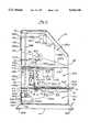
- FIG. 1is a perspective view of the digital image capture housing of the present invention.
- FIG, 2is a block diagram showing the present invention in the environment of a computer network.
- FIG. 3sets forth in block diagram format the components of the digital image capture system of the present invention.
- FIG. 4is an illustration setting forth the various components contained within the housing of the digital image capture device of the present invention as shown in FIG. 1.
- FIGS. 5(a)-(c)set forth the details of the bezel of the present invention.
- FIGS. 6(a)-(c)set forth the details of the bracket for holding the camera contained within the housing of the present invention.
- FIG. 7sets forth the details of the power wire assembly of the present invention.
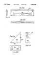
- FIGS. 8(a)-(b)set forth the details of the collar for adjusting the focus of the camera.
- FIGS. 9(a)-(c)set forth the details of the slide tray of the present invention.
- FIG. 10sets forth the details of the tray insert of the present invention.
- FIG. 11sets forth the wiring diagram for the housing of the present invention.
- FIG. 1an illustration setting forth the general components of the digital image capture device 10 of the present invention is shown.
- the device 10includes a housing 20, a support base 30, a formed slot 40, a sliding tray 13, and a recess 60 for holding a card 70.
- cardrefers to a driver's license, a bank card, an ID card, a passport, or to any document that contains a photo or information.
- the user of the present inventionplaces card 70 into recess 60 and then slides the tray 13 in the direction of arrow 80 into slot 40 into a first fully inserted position.
- a digital imageis then taken of the card 70 by a video camera stored within the housing 20.
- the tray 13is slid in a direction opposite that of arrow 80 into a second fully opened position and the card 70 is removed.
- card 70can be flipped over and replaced into the recess 60 so that the obverse side of the card can also have its video image captured.
- housing 20 and the base 30are of a preferred design, any suitable design could be utilized. Likewise, the provision of a base 30 is optional under the teachings of the present invention. Finally, the slot 40 and the tray 13 can be located in any suitable orientation or position in the housing 20,
- a cable 12interconnects to the interior of the housing 20 that enables the captured video image to be delivered out from the device 10 to a remote location.
- the digital image capture device 10can be used in a system environment as shown in FIG. 2.
- the device 10is interconnected over lines 12 to a computer 200 such as a standard personal computer operating, for example, at 66 MHz.
- the computer 200has a monitor, keyboard, and other standard and conventional components.
- the computer 200is interconnected over a network 210 to other computers 220.
- the network 210can be any suitable network such as a Novell Network.
- Each computer 220, like computer 200,is a standard conventional personal computer.
- a second video camera 230that is interconnected over lines 232 to computer 200.
- Camera 230is an option under the teachings of the present invention, but serves an important function. In the event that the card 70 does not carry the owner's photograph, camera 230 captures the owner's likeness 240.
- the camera 230may be preset so no focusing or adjusting by the operator is required.
- the computer 200is designed so that only single keystroke commands on the keyboard are used to control the computer program interface.
- the system shown in FIG. 2functions as follows.
- the card 70is inputted into the digital image capture device 10 to capture a digital image of the card 70.
- the digital imageis then delivered over lines 12 to the computer 200 for storage.
- a digital photo of the person 240 who owns the card 70is also required, that image is captured by camera 230 and delivered over lines 232 to computer 200 for storage.
- Operators of computers 220 at remote locationssuch as managers in the casino can then type in the person's name and instantly view a digital image of card 70 and/or a digital likeness of the person 240 as retrieved by camera 230.
- the manager or other personcan then verify the individual's identity and any associated signatures or other information.
- the details of the computer 200are shown in FIG. 3.
- the computer 200includes a conventional monitor 300 driven by a CPU 310.
- the CPU 310receives input commands from a mouse, a keyboard 320, or the like.
- the CPU 310is interconnected to the network 210 through a standard network card 330.
- the CPU 310is also interconnected to a standard image capture card 340 that is connected to lines 12 (to the capture device 10) and to lines 232 (to the camera 230).
- the CPU 310builds a card database 350 based on the images captured by device 10.
- the CPU 310may optionally build a likeness database 360 based on the likeness images from camera 230.
- the device 10has a housing or chassis cover 20.
- the cover 20is composed of metal preformed in the shape shown in FIGS. I and 4.
- Mounted on the exterior of the housing 20is a document drawer bezel 400 containing slot 40.
- the details of the bezel 400are shown in FIG. 5, which more clearly illustrates the slot 40.
- the bezelis rectangular and is made from plastic or nylon material.
- the slot 40is also rectangular, having a preferred dimension of about 0.4" ⁇ 5.2". It is to be expressly understood that any suitable design or shape for the bezel 400 of the present invention could be utilized.
- the bezel 400is mounted to the housing 20 by means of screws 402.
- the base 30At the bottom of the housing 20 is mounted the base 30, which is connected to the housing by means of screws 32 (only one of which is shown in FIG. 4). Rubber feet 404 are mounted on the base 30.
- the camera 422is mounted to a camera mounting bracket 421 by means of camera mounting screws 423.
- FIG. 6The details of the camera mounting bracket 421 are shown in FIG. 6.
- the camera mounting bracket 421is triangular as shown in FIG. 6(a) having three walls 600, 610, and 620.
- the use of the triangular shape and three walls 600, 610, and 620provides a very rigid support structure for the camera 422.
- wall 610has slots 612 and 614 formed therein
- wall 620has slots 622 and 624 formed therein. Slots 622 and 624 are receptive of camera mounting screws 423 as shown in FIG. 4.
- Slots 612 and 614 in wall 610are receptive of screws 418 as shown in FIG. 4 for mounting the wall 610 to support plate 412, which crosses through housing 20.
- the camera 422is rigidly mounted to bracket 421, which in turn is rigidly mounted to housing 20 by means of plate 412.
- a video cable 437interconnects to a connector 422(a) in a conventional fashion to camera 422.
- the video cable 437connects to a video output jack 433 on the exterior of the housing 20.
- cable 12interconnects with jack 433 to deliver the video signals out from the housing 20.
- Camera 422receives DC power over power cable 438, which is interconnected to a power jack 434 also located on the exterior of the housing 20.
- the power jack 434is conventionally interconnected to a 12-volt DC power support source (not shown) by power cable 90 (shown in FIG. 1).
- a ground terminal locking nut 435engages a corresponding threaded stud 435(a) so that a ground cable can be connected to ground the housing 20 in a conventional fashion.
- a conventional on/off rocker switch 429serially interrupts power in the cable 438 to enable the operator of the device 10 of the present invention to turn power on and off to the camera 422.
- Power cable 438is delivered through a grommet 412.
- Grommet 412encircles a formed hole in a mounting plate 413, extending across the housing 20 as shown in FIG. 4.
- the camera 422is rigidly mounted in the interior of the housing 20 and selectively receives power from a DC source external of the housing 20 and delivers captured video image signals out from the housing 20. It is to be expressly understood that the position and orientation of the camera 422, cable 437, and cable 438 are a matter of design choice and that any suitable orientation or location can also be utilized under the teachings of the present invention.
- a vent or grill 430is provided for a formed opening 430(a) in the housing 20. This provides ventilation to the interior of the housing 20.
- the grill 430is conventionally mounted by screws 431.
- FIG. 7The details of the power wire assembly are shown in FIG. 7.
- the wiringis conventional. However, the wiring 438(a) should be twisted a minimum of one turn per inch as illustrated in FIG. 7 at region 700.
- Plate 412is also triangular as witnessed by edge 412(a). Plate 412 defines a compartment 20(a) in which is contained the camera 422. Plate 412 is affixed to the housing 20 by means of a screws 412(b). Plate 413 also has a triangular edge 413(a) and a rear plate portion 413(b). Plate 413 is also affixed to the housing 20 by means of a screw, not shown. Plate 413 defines two compartments 20(b) and 20(c). Plate 412 has a formed opening 412(d) through which the lens 424 of the camera 422 extends.
- a camera lens focus cylinder or collar 425surrounds the lens 424.
- FIG. 8sets forth the collar 425.
- the collar 425is cylindrical and at one end has a formed annular region 800 that forms an adjustment tack.
- a formed hole 810is drilled into the side of the collar 425.
- the hole 810is shown in FIG. 8(b) and extends through both sides of the collar.
- a set screw 426 as shown in FIG. 4is used in each hole 810 to firmly attach the collar to the lens 424.
- the collar 425is made from plastic or nylon material.
- the interior 820 of the collaris configured to conform substantially with the outer shape of the lens 424.
- a camera focus adjustment belt 427engages tack 800 in collar 425. This is shown in FIG. 4.
- the camera focus adjustment belt 427engages a rubber thumb wheel 419 that is mounted by a shoulder screw 420 to plate 412.
- the housing 20has a formed opening 420(a) that provides access to the rubber thumb wheel 419.
- a focus adjustment cover plate 436is affixed by means of a screw 418 to the housing 20. When the cover plate 436 is removed, by removing screw 418, the thumb wheel 419 can be selectively moved, which causes belt 427 to correspondingly move collar 425 to adjust the focus of the lens 424 of the camera 422.
- the cover plate 436 when affixed to the housing 20is designed to be a tight flush engagement so as to prevent light from entering enclosed region 20(b).
- the document drawer or slide tray 13is selectively operating on plate 413.
- the tray 13is rectangular with sides 900 being longer than ends 910.
- the front 910b of the tray 13, as shown in FIG. 1,extends outwardly from the housing 20.
- the front edge 910b, as shown in FIG. 9(b)has an upstanding lip 912.
- the sides 900 of tray 13also have an upstanding lip 902.
- each upstanding lip 902has an inwardly directed flange 904. This is best illustrated in FIG. 9(b).
- the bottom 920 of the tray 13has a formed hole 930.
- the rear 910a of the tray 13also has a raised upstanding lip 912, and as shown in FIG. 9(c), the central portion of lip 912 has an upwardly extending portion 914.
- a second formed hole 940Near the rear 910a and centrally located in the bottom 920 is a second formed hole 940 to which is affixed a connector 950 as shown in FIG. 9(c).
- FIG. 10In the bottom 920 of the tray 13 is placed a plastic document alignment insert 14 as shown in FIG. 4.
- insert 14is rectangular and has a formed rectangular hole 1000 as illustrated.
- the hole 1000is configured to be slightly larger than a standard credit card, and in the preferred embodiment the dimensions are about 3.4 inches for side 1010 and about 2.2 inches for side 1020. This dimension accommodates most conventional cards.
- this insertcan be designed to accommodate any type of card or document of any suitable size.
- the operator of the device 10 of the present inventioncan have a number of different inserts 14 to accommodate different sized documents. Each insert 14 can be quickly inserted into the tray 13 as shown in FIG.
- the thickness of the insert 14is about half the height of the lips 902 for the tray 13.
- the tray 13is slidably mounted to plate 413 by means of a slide washer 15, a spring washer 16, and a spacer washer 17, all of which are held in place by means of screw 18 to connector 950 on the bottom 920 of the tray 13.
- the slot in which connector 950 slidesis shown in FIG. 4 as 413s.
- a document drawer-actuated light switch 8mounted at the rear of the tray when fully inserted into the housing 20 is a document drawer-actuated light switch 8.
- the light switch 8is conventionally mounted by screw 9 to the rear wall 6.
- the micro-switch 8has a sensor 8a that extends through the wall 6 to abut against extension 914 of the tray 13. Hence, when the tray 13 is fully inserted into the housing 20, extension 914 abuts against sensor 8a to place the micro-switch 8 in an activated position. When the tray 13 is slightly moved outwardly, the extension 914 does not abut against the sensor 8a and the micro-switch 8 is in the off position.
- a document drawer hold magnet 7that is selectively used to hold the tray 13 in the fully inserted position. This is important to provide a stable environment wherein the extension 914 fully engages the sensor 8a of the micro-switch 8. Magnet 7 also firmly holding the drawer 13 also ensures full insertion and minimizes any vibration of the tray while the image is being captured.
- each mount 410contains a light 410a.
- the mounts 410are mounted on directly opposing walls of the housing 20 on opposite sides of the insert 14 of FIG. 10.
- the general locations of the bulbs 410aare shown by dotted lines 1030 in FIG. 10 with respect to the formed opening 1000. With this orientation, the card placed within formed opening 1000 is fully illuminated and the entire image of the card is delivered through the lens (shown by dotted lines 1040 in FIG. 10) of the camera 422. It is to be expressly understood that the dotted lines shown in FIG. 10 are for purposes of illustration to show general locations of the bulbs 1030 and the lens 1040 when the tray carrying the insert 14 is fully inserted into the housing 20.
- the wiring diagram of the present inventionis set forth.
- the power connector 434delivers the DC power into cable 438b, which is connected to rocker switch 429.
- the DC poweris then delivered through connectors 1100 to cable 438, which delivers DC power through connector 1110 to the video camera 422, and through cable 438c to the micro-switch 8 and then to the lights 410a.
- the wiring diagram of FIG. 11is conventional in design.
- Region 20b of the digital image capture device 10 of the present inventionserves as a light box in which the card receives proper lighting from lights 410a.
- the miniature color CCD camera 422 and its lens 424are used to photographically capture an image of the desired card. All of the remaining components in housing 20 facilitate an automated process of digital image capturing of the card.
- the desired card 70is placed in the plastic document alignment insert 14, which is, in turn, held in place by the document drawer or tray 13.
- the document tray 13slides freely in slot 413s, which is centered and located just below the tray 13 as shown in FIG. 4.
- magnet 7holds the tray in a fully inserted position to ensure that the light switch 8 remains actuated for the duration of the image capturing process.
- incandescent lamps 410aare placed at precise angles adjacent to and on each side of the document viewing area 1000 that contains the card 70. Power to the lamps 410a is controlled by light switch 8. The lamps 410a are switched on and off to save power, to prevent heat buildup, and to provide the operator of the device 10 with a visual indication that the drawer is fully seated. Lighting of the document viewing area 1000 is also enhanced by providing a light or white color to all inner surfaces of region 20b.
- the document viewing arearefers to the area as seen through the lens 424 of the camera 422.
- a focusing mechanismis provided by the rubber thumb wheel 419, the focus adjustment belt 427, and the camera lens focus adjustment cylinder 425. This externally accessible adjustment is used to fine tune the lens focus after the unit has been shipped or if some other event occurs that can inadvertently change the focus adjustment.
- Power to the lamps 410a and to the CCD color camera 422is provided by an external, regulated, 12-volt DC power supply preferably rated at 2.5 amps. It is connected through the power jack 434, and as set forth in FIG. 11, is wired to the lamps, the light switch, and the camera. The video signal from the camera is fed through a shielded cable 437 to the rear of the housing 20. Jack 433 is used to connect the video signal from the camera to the host computer 200 and specifically to the digital image capture interface board 340 as shown in FIG. 3.
- the chassis base 30is used to stabilize the device 10 while providing aesthetic appeal and a firm mounting base.
Landscapes
- Engineering & Computer Science (AREA)
- Multimedia (AREA)
- Signal Processing (AREA)
- Studio Devices (AREA)
Abstract
Description
Claims (11)
Priority Applications (3)
| Application Number | Priority Date | Filing Date | Title |
|---|---|---|---|
| US08/250,664US5642160A (en) | 1994-05-27 | 1994-05-27 | Digital image capture system for photo identification cards |
| PCT/US1995/006025WO1995033339A1 (en) | 1994-05-27 | 1995-05-22 | Digital image capture system for photo identification cards |
| AU25889/95AAU2588995A (en) | 1994-05-27 | 1995-05-22 | Digital image capture system for photo identification cards |
Applications Claiming Priority (1)
| Application Number | Priority Date | Filing Date | Title |
|---|---|---|---|
| US08/250,664US5642160A (en) | 1994-05-27 | 1994-05-27 | Digital image capture system for photo identification cards |
Publications (1)
| Publication Number | Publication Date |
|---|---|
| US5642160Atrue US5642160A (en) | 1997-06-24 |
Family
ID=22948670
Family Applications (1)
| Application Number | Title | Priority Date | Filing Date |
|---|---|---|---|
| US08/250,664Expired - LifetimeUS5642160A (en) | 1994-05-27 | 1994-05-27 | Digital image capture system for photo identification cards |
Country Status (3)
| Country | Link |
|---|---|
| US (1) | US5642160A (en) |
| AU (1) | AU2588995A (en) |
| WO (1) | WO1995033339A1 (en) |
Cited By (49)
| Publication number | Priority date | Publication date | Assignee | Title |
|---|---|---|---|---|
| US5745166A (en)* | 1994-07-26 | 1998-04-28 | Maxpro Systems Pty Ltd | Video security system field of the invention |
| US5748755A (en)* | 1992-05-08 | 1998-05-05 | Moore Business Forms, Inc. | Picture checks |
| US5960100A (en)* | 1997-07-23 | 1999-09-28 | Hargrove; Tom | Credit card reader with thumb print verification means |
| US6035074A (en)* | 1997-05-27 | 2000-03-07 | Sharp Kabushiki Kaisha | Image processing apparatus and storage medium therefor |
| US6038012A (en)* | 1997-11-17 | 2000-03-14 | Optical & Electronic Research | Photo identification card system |
| US6119932A (en)* | 1997-02-18 | 2000-09-19 | Protech Video Security, Inc. | Identification verification apparatus and method |
| US6172672B1 (en) | 1996-12-18 | 2001-01-09 | Seeltfirst.Com | Method and system for providing snapshots from a compressed digital video stream |
| US6224109B1 (en)* | 1999-08-07 | 2001-05-01 | James Yung Chien Yang | Credit card with driver's license or identification |
| US6256737B1 (en) | 1999-03-09 | 2001-07-03 | Bionetrix Systems Corporation | System, method and computer program product for allowing access to enterprise resources using biometric devices |
| US6341169B1 (en) | 1999-02-08 | 2002-01-22 | Pulse Systems, Inc. | System and method for evaluating a document and creating a record of the evaluation process and an associated transaction |
| US20030002730A1 (en)* | 2001-07-02 | 2003-01-02 | Petrich David B. | System and method for discovering and categorizing attributes of a digital image |
| US6628887B1 (en) | 1998-04-17 | 2003-09-30 | Honeywell International, Inc. | Video security system |
| US20040014523A1 (en)* | 2002-07-17 | 2004-01-22 | Kastner Steven Robert | Method and apparatus for enrolling gaming device players into a player-tracking system |
| US20040022420A1 (en)* | 1993-10-06 | 2004-02-05 | 3M Innovative Properties Company | Security reader for automatic detection of tampering and alteration |
| US6695203B2 (en)* | 2001-12-13 | 2004-02-24 | Omron Corporation | Boarding pass processing unit, boarding gate reader, person collation unit, boarding system, boarding pass, boarding pass processing method, service kiosk for boarding pass |
| US6707989B1 (en) | 2003-05-14 | 2004-03-16 | Ka'ahumanu Laki Po'maikai | Method and apparatus for providing baggage identification tags |
| USD490460S1 (en) | 2002-02-01 | 2004-05-25 | Datacard Corporation | Front panel and hood of a module of a card personalization system |
| US6758394B2 (en)* | 2001-07-09 | 2004-07-06 | Infonox On The Web | Identity verification and enrollment system for self-service devices |
| US20040173673A1 (en)* | 2003-03-06 | 2004-09-09 | Cash Systems, Inc. | System and method for performing a quasi-cash transaction |
| US20040181449A1 (en)* | 2003-02-13 | 2004-09-16 | Gamesman Limited | Award indicating device |
| US6845913B2 (en)* | 1999-02-11 | 2005-01-25 | Flir Systems, Inc. | Method and apparatus for barcode selection of themographic survey images |
| US20050098633A1 (en)* | 2000-09-06 | 2005-05-12 | Paul Poloniewicz | Zero-footprint camera-based point-of-sale bar code presentation scanning system |
| US20050107155A1 (en)* | 2003-10-01 | 2005-05-19 | Cash Systems, Inc. | Multi-function cashless gaming ATM |
| US6907135B2 (en)* | 1997-03-03 | 2005-06-14 | British Telecommunications Public Limited Company | Security check provision |
| US20050196021A1 (en)* | 2004-02-27 | 2005-09-08 | Fuji Photo Film Co., Ltd. | Card issuing system, card issuing method, and machine readable medium storing thereon card issuing program |
| US20060065714A1 (en)* | 2004-09-28 | 2006-03-30 | 3M Innovative Properties Company | Passport reader for processing a passport having an RFID element |
| US20060072822A1 (en)* | 2004-10-06 | 2006-04-06 | Iuval Hatzav | System for extracting information from an identity card |
| US20060147093A1 (en)* | 2003-03-03 | 2006-07-06 | Takashi Sanse | ID card generating apparatus, ID card, facial recognition terminal apparatus, facial recognition apparatus and system |
| US20060160610A1 (en)* | 2004-10-29 | 2006-07-20 | Cash Systems, Inc. | System and method for performing a financial transaction in an entertainment center |
| US7305562B1 (en) | 1999-03-09 | 2007-12-04 | Citibank, N.A. | System, method and computer program product for an authentication management infrastructure |
| US7327959B2 (en)* | 2001-12-17 | 2008-02-05 | Telecast Fiber Systems, Inc. | Camera-mountable fiber optic transceiver system |
| US7382911B1 (en)* | 2001-02-16 | 2008-06-03 | Hand Held Products, Inc. | Identification card reader |
| US7441263B1 (en) | 2000-03-23 | 2008-10-21 | Citibank, N.A. | System, method and computer program product for providing unified authentication services for online applications |
| US20090065573A1 (en)* | 2004-09-09 | 2009-03-12 | Cash Systems, Inc. | System and method for checkless cash advance settlement |
| US20110082777A1 (en)* | 2009-10-06 | 2011-04-07 | Chess Steven M | Timekeeping Computer System with Image Capture and Quick View |
| US20110276445A1 (en)* | 2009-10-06 | 2011-11-10 | Chess Steven M | Timekeeping Computer System with Image Capture and Quick View |
| USD702237S1 (en) | 2013-01-11 | 2014-04-08 | Hand Held Products, Inc. | Imaging terminal |
| US8777109B2 (en) | 2012-10-04 | 2014-07-15 | Hand Held Products, Inc. | Customer facing imaging systems and methods for obtaining images |
| US8832805B1 (en)* | 2011-08-08 | 2014-09-09 | Amazon Technologies, Inc. | Verifying user information |
| US20150262113A1 (en)* | 2014-03-11 | 2015-09-17 | Bank Of America Corporation | Work status monitoring and reporting |
| US9437073B2 (en) | 2004-10-01 | 2016-09-06 | Everi Payments Inc. | System and method for integrated multiple source player cash access |
| US9875612B2 (en) | 2012-05-17 | 2018-01-23 | Everi Payments Inc. | Pre-authorized casino credit instrument |
| US10748381B2 (en) | 2004-09-09 | 2020-08-18 | Everi Payments Inc. | System and method for integrated multiple source player cash access |
| US11068677B1 (en)* | 2020-08-26 | 2021-07-20 | Hin Leong Tan | Card reader |
| US11205321B2 (en) | 2003-10-01 | 2021-12-21 | Everi Payments Inc. | System and method for redeeming cashless gaming tickets to bank accounts via multifunction ATM |
| US20220147728A1 (en)* | 2020-08-26 | 2022-05-12 | Hin Leong Tan | Card reader |
| US20230367980A1 (en)* | 2022-05-12 | 2023-11-16 | Hin Leong Tan | Duplex card scanner |
| US20230368446A1 (en)* | 2022-05-12 | 2023-11-16 | Hin Leong Tan | Duplex card scanner lighting |
| US20250259233A1 (en)* | 2024-02-13 | 2025-08-14 | Sultan Abdulaziz Alturki | Earned compensation access system with internal and external funding options for compensation payment before payday |
Families Citing this family (1)
| Publication number | Priority date | Publication date | Assignee | Title |
|---|---|---|---|---|
| DE19611041C2 (en)* | 1996-03-20 | 2001-01-25 | Karl Stefan Riener | Shooting range management system and method for carrying out a local shooting operation |
Citations (13)
| Publication number | Priority date | Publication date | Assignee | Title |
|---|---|---|---|---|
| US3564132A (en)* | 1966-01-17 | 1971-02-16 | Mardix | Apparatus for controlling the passage of persons and objects between two areas utilizing closed circuit television |
| US3997723A (en)* | 1974-08-19 | 1976-12-14 | Visual Methods, Inc. | Compact unit for optical security system |
| US4121249A (en)* | 1972-08-02 | 1978-10-17 | Lemelson Jerome H | Card recording and reproduction apparatus and method |
| US4734567A (en)* | 1985-09-18 | 1988-03-29 | Siemens Aktiengesellschaft | Locking and unlocking device for a card reader |
| US4794583A (en)* | 1987-04-28 | 1988-12-27 | Pioneer Electronic Corporation | Disk loader |
| US4805222A (en)* | 1985-12-23 | 1989-02-14 | International Bioaccess Systems Corporation | Method and apparatus for verifying an individual's identity |
| US4821118A (en)* | 1986-10-09 | 1989-04-11 | Advanced Identification Systems, Inc. | Video image system for personal identification |
| US4982072A (en)* | 1987-02-09 | 1991-01-01 | Hitachi, Ltd. | Driver license check system with IC card and method therefor |
| US4993068A (en)* | 1989-11-27 | 1991-02-12 | Motorola, Inc. | Unforgeable personal identification system |
| US5072246A (en)* | 1989-11-20 | 1991-12-10 | Thayer Donald O | Self photography booth and method |
| US5075769A (en)* | 1987-03-03 | 1991-12-24 | Polaroid Corporation | Video identification card system |
| US5199081A (en)* | 1989-12-15 | 1993-03-30 | Kabushiki Kaisha Toshiba | System for recording an image having a facial image and id information |
| EP0560574A2 (en)* | 1992-03-11 | 1993-09-15 | Roger Kuhns | Low cost method employing time slots for thwarting fraud in the periodic issuance of food stamps, unemployment benefits or other governmental human services |
- 1994
- 1994-05-27USUS08/250,664patent/US5642160A/ennot_activeExpired - Lifetime
- 1995
- 1995-05-22AUAU25889/95Apatent/AU2588995A/ennot_activeAbandoned
- 1995-05-22WOPCT/US1995/006025patent/WO1995033339A1/enactiveApplication Filing
Patent Citations (13)
| Publication number | Priority date | Publication date | Assignee | Title |
|---|---|---|---|---|
| US3564132A (en)* | 1966-01-17 | 1971-02-16 | Mardix | Apparatus for controlling the passage of persons and objects between two areas utilizing closed circuit television |
| US4121249A (en)* | 1972-08-02 | 1978-10-17 | Lemelson Jerome H | Card recording and reproduction apparatus and method |
| US3997723A (en)* | 1974-08-19 | 1976-12-14 | Visual Methods, Inc. | Compact unit for optical security system |
| US4734567A (en)* | 1985-09-18 | 1988-03-29 | Siemens Aktiengesellschaft | Locking and unlocking device for a card reader |
| US4805222A (en)* | 1985-12-23 | 1989-02-14 | International Bioaccess Systems Corporation | Method and apparatus for verifying an individual's identity |
| US4821118A (en)* | 1986-10-09 | 1989-04-11 | Advanced Identification Systems, Inc. | Video image system for personal identification |
| US4982072A (en)* | 1987-02-09 | 1991-01-01 | Hitachi, Ltd. | Driver license check system with IC card and method therefor |
| US5075769A (en)* | 1987-03-03 | 1991-12-24 | Polaroid Corporation | Video identification card system |
| US4794583A (en)* | 1987-04-28 | 1988-12-27 | Pioneer Electronic Corporation | Disk loader |
| US5072246A (en)* | 1989-11-20 | 1991-12-10 | Thayer Donald O | Self photography booth and method |
| US4993068A (en)* | 1989-11-27 | 1991-02-12 | Motorola, Inc. | Unforgeable personal identification system |
| US5199081A (en)* | 1989-12-15 | 1993-03-30 | Kabushiki Kaisha Toshiba | System for recording an image having a facial image and id information |
| EP0560574A2 (en)* | 1992-03-11 | 1993-09-15 | Roger Kuhns | Low cost method employing time slots for thwarting fraud in the periodic issuance of food stamps, unemployment benefits or other governmental human services |
Cited By (102)
| Publication number | Priority date | Publication date | Assignee | Title |
|---|---|---|---|---|
| US5748755A (en)* | 1992-05-08 | 1998-05-05 | Moore Business Forms, Inc. | Picture checks |
| US20040022420A1 (en)* | 1993-10-06 | 2004-02-05 | 3M Innovative Properties Company | Security reader for automatic detection of tampering and alteration |
| US20060139622A1 (en)* | 1993-10-06 | 2006-06-29 | 3M Innovative Properties Company | Security reader for automatic detection of tampering and alteration |
| US7259841B2 (en)* | 1993-10-06 | 2007-08-21 | 3M Innovative Properties Company | Security reader for automatic detection of tampering and alteration |
| US7821621B2 (en) | 1993-10-06 | 2010-10-26 | 3M Innovative Properties Company | Security reader for automatic detection of tampering and alteration |
| US5923364A (en)* | 1994-07-26 | 1999-07-13 | Maxpro Systems Pty Ltd | Video security system |
| US5745166A (en)* | 1994-07-26 | 1998-04-28 | Maxpro Systems Pty Ltd | Video security system field of the invention |
| US6166763A (en)* | 1994-07-26 | 2000-12-26 | Ultrak, Inc. | Video security system |
| US6172672B1 (en) | 1996-12-18 | 2001-01-09 | Seeltfirst.Com | Method and system for providing snapshots from a compressed digital video stream |
| US6119932A (en)* | 1997-02-18 | 2000-09-19 | Protech Video Security, Inc. | Identification verification apparatus and method |
| US6907135B2 (en)* | 1997-03-03 | 2005-06-14 | British Telecommunications Public Limited Company | Security check provision |
| US20050147279A1 (en)* | 1997-03-03 | 2005-07-07 | British Telecommunications Plc. | Security check provision |
| US7424135B2 (en) | 1997-03-03 | 2008-09-09 | British Telecommunications, Plc | Security check provision |
| US6035074A (en)* | 1997-05-27 | 2000-03-07 | Sharp Kabushiki Kaisha | Image processing apparatus and storage medium therefor |
| US5960100A (en)* | 1997-07-23 | 1999-09-28 | Hargrove; Tom | Credit card reader with thumb print verification means |
| US6038012A (en)* | 1997-11-17 | 2000-03-14 | Optical & Electronic Research | Photo identification card system |
| US6628887B1 (en) | 1998-04-17 | 2003-09-30 | Honeywell International, Inc. | Video security system |
| US6341169B1 (en) | 1999-02-08 | 2002-01-22 | Pulse Systems, Inc. | System and method for evaluating a document and creating a record of the evaluation process and an associated transaction |
| US6845913B2 (en)* | 1999-02-11 | 2005-01-25 | Flir Systems, Inc. | Method and apparatus for barcode selection of themographic survey images |
| US9398013B2 (en) | 1999-03-09 | 2016-07-19 | Citibank, N.A. | System, method and computer program product for an authentication management infrastructure |
| US8132226B1 (en) | 1999-03-09 | 2012-03-06 | Citibank, N.A. | System, method and computer program product for an authentication management infrastructure |
| US7305562B1 (en) | 1999-03-09 | 2007-12-04 | Citibank, N.A. | System, method and computer program product for an authentication management infrastructure |
| US6256737B1 (en) | 1999-03-09 | 2001-07-03 | Bionetrix Systems Corporation | System, method and computer program product for allowing access to enterprise resources using biometric devices |
| US8707388B1 (en) | 1999-03-09 | 2014-04-22 | Citibank, N.A. | System, method and computer program product for an authentication management infrastructure |
| US6224109B1 (en)* | 1999-08-07 | 2001-05-01 | James Yung Chien Yang | Credit card with driver's license or identification |
| US7441263B1 (en) | 2000-03-23 | 2008-10-21 | Citibank, N.A. | System, method and computer program product for providing unified authentication services for online applications |
| US9009798B2 (en) | 2000-03-23 | 2015-04-14 | Citibank, N.A. | System, method and computer program product for providing unified authentication services for online applications |
| US9438633B1 (en) | 2000-03-23 | 2016-09-06 | Citibank, N.A. | System, method and computer program product for providing unified authentication services for online applications |
| US7395970B2 (en)* | 2000-09-06 | 2008-07-08 | Symbol Technologies, Inc. | Zero-footprint camera-based point-of-sale bar code presentation scanning system |
| US20050098633A1 (en)* | 2000-09-06 | 2005-05-12 | Paul Poloniewicz | Zero-footprint camera-based point-of-sale bar code presentation scanning system |
| US7382911B1 (en)* | 2001-02-16 | 2008-06-03 | Hand Held Products, Inc. | Identification card reader |
| US7113633B2 (en) | 2001-07-02 | 2006-09-26 | Photoinaphoto.Com, Inc. | System and method for discovering and categorizing attributes of a digital image |
| US20030002730A1 (en)* | 2001-07-02 | 2003-01-02 | Petrich David B. | System and method for discovering and categorizing attributes of a digital image |
| US7764829B2 (en) | 2001-07-02 | 2010-07-27 | Petrich David B | System and method for discovering and categorizing attributes of a digital image |
| US20060280368A1 (en)* | 2001-07-02 | 2006-12-14 | Photoinaphoto.Com, Inc. | System and method for discovering and categorizing attributes of a digital image |
| US6758394B2 (en)* | 2001-07-09 | 2004-07-06 | Infonox On The Web | Identity verification and enrollment system for self-service devices |
| US6695203B2 (en)* | 2001-12-13 | 2004-02-24 | Omron Corporation | Boarding pass processing unit, boarding gate reader, person collation unit, boarding system, boarding pass, boarding pass processing method, service kiosk for boarding pass |
| US7327959B2 (en)* | 2001-12-17 | 2008-02-05 | Telecast Fiber Systems, Inc. | Camera-mountable fiber optic transceiver system |
| USD490460S1 (en) | 2002-02-01 | 2004-05-25 | Datacard Corporation | Front panel and hood of a module of a card personalization system |
| US20040014523A1 (en)* | 2002-07-17 | 2004-01-22 | Kastner Steven Robert | Method and apparatus for enrolling gaming device players into a player-tracking system |
| US7988553B2 (en) | 2002-07-17 | 2011-08-02 | Igt | Method and apparatus for enrolling gaming device players into a player-tracking system |
| US20040181449A1 (en)* | 2003-02-13 | 2004-09-16 | Gamesman Limited | Award indicating device |
| US20060147093A1 (en)* | 2003-03-03 | 2006-07-06 | Takashi Sanse | ID card generating apparatus, ID card, facial recognition terminal apparatus, facial recognition apparatus and system |
| US20040173673A1 (en)* | 2003-03-06 | 2004-09-09 | Cash Systems, Inc. | System and method for performing a quasi-cash transaction |
| US6951302B2 (en)* | 2003-03-06 | 2005-10-04 | Cash Systems, Inc. | System and method for performing a quasi-cash transaction |
| US6707989B1 (en) | 2003-05-14 | 2004-03-16 | Ka'ahumanu Laki Po'maikai | Method and apparatus for providing baggage identification tags |
| US11488446B2 (en) | 2003-10-01 | 2022-11-01 | Even Payments, Inc. | Multi-function cashless gaming ATM |
| US11735003B2 (en) | 2003-10-01 | 2023-08-22 | Everi Payments Inc. | System and method for redeeming cashless gaming tickets to bank accounts via multi-function ATM |
| US10275983B2 (en) | 2003-10-01 | 2019-04-30 | Everi Payments Inc. | Multi-function cashless gaming ATM |
| US10839647B2 (en) | 2003-10-01 | 2020-11-17 | Everi Payments Inc. | Multi-function cashless gaming ATM |
| US8696463B2 (en) | 2003-10-01 | 2014-04-15 | Global Cash Access, Inc. | System and method for integrated player tracking and cash-access |
| US20050107156A1 (en)* | 2003-10-01 | 2005-05-19 | Cash Systems, Inc. | System and method for integrated player tracking and cash-access |
| US9324210B2 (en) | 2003-10-01 | 2016-04-26 | Everi Payments Inc. | Multi-function cashless gaming ATM |
| US11205321B2 (en) | 2003-10-01 | 2021-12-21 | Everi Payments Inc. | System and method for redeeming cashless gaming tickets to bank accounts via multifunction ATM |
| US8556707B2 (en) | 2003-10-01 | 2013-10-15 | Global Cash Access, Inc. | Multi-function cashless gaming ATM |
| US20050107155A1 (en)* | 2003-10-01 | 2005-05-19 | Cash Systems, Inc. | Multi-function cashless gaming ATM |
| US7526107B2 (en)* | 2004-02-27 | 2009-04-28 | Fujifilm Corporation | Card issuing system, card issuing method, and machine readable medium storing thereon card issuing program |
| US20050196021A1 (en)* | 2004-02-27 | 2005-09-08 | Fuji Photo Film Co., Ltd. | Card issuing system, card issuing method, and machine readable medium storing thereon card issuing program |
| US10134234B2 (en) | 2004-09-09 | 2018-11-20 | Everi Payments Inc. | System and method for integrated multiple source player cash access |
| US10535226B2 (en) | 2004-09-09 | 2020-01-14 | Everi Payments Inc. | System and method for checkless cash advance settlement |
| US12067839B2 (en) | 2004-09-09 | 2024-08-20 | Everi Payments Inc. | System and method for integrated multiple source player cash access |
| US11501608B2 (en) | 2004-09-09 | 2022-11-15 | Even Payments Inc. | System and method for integrated multiple source player cash access |
| US10909808B2 (en) | 2004-09-09 | 2021-02-02 | Everi Payments Inc. | System and method for checkless cash advance settlement |
| US20090065573A1 (en)* | 2004-09-09 | 2009-03-12 | Cash Systems, Inc. | System and method for checkless cash advance settlement |
| US10748381B2 (en) | 2004-09-09 | 2020-08-18 | Everi Payments Inc. | System and method for integrated multiple source player cash access |
| US9959585B2 (en) | 2004-09-09 | 2018-05-01 | Everi Payments Inc. | System and method for checkless cash advance settlement |
| US9171303B2 (en) | 2004-09-09 | 2015-10-27 | Everi Payments, Inc. | System and method for checkless cash advance settlement |
| US9224143B2 (en) | 2004-09-09 | 2015-12-29 | Everi Payments, Inc. | System and method for checkless cash advance settlement |
| US9524532B2 (en) | 2004-09-09 | 2016-12-20 | Everi Payments Inc. | System and method for integrated multiple source player cash access |
| US8025216B2 (en) | 2004-09-09 | 2011-09-27 | Global Cash Access, Inc. | System and method for checkless cash advance settlement |
| US20060065714A1 (en)* | 2004-09-28 | 2006-03-30 | 3M Innovative Properties Company | Passport reader for processing a passport having an RFID element |
| US7591415B2 (en)* | 2004-09-28 | 2009-09-22 | 3M Innovative Properties Company | Passport reader for processing a passport having an RFID element |
| US9437073B2 (en) | 2004-10-01 | 2016-09-06 | Everi Payments Inc. | System and method for integrated multiple source player cash access |
| US7911655B2 (en)* | 2004-10-06 | 2011-03-22 | Iuval Hatzav | System for extracting information from an identity card |
| US20060072822A1 (en)* | 2004-10-06 | 2006-04-06 | Iuval Hatzav | System for extracting information from an identity card |
| US7922581B2 (en) | 2004-10-29 | 2011-04-12 | Global Cash Access, Inc. | System and method for performing a financial transaction in an entertainment center |
| US20060160610A1 (en)* | 2004-10-29 | 2006-07-20 | Cash Systems, Inc. | System and method for performing a financial transaction in an entertainment center |
| US20110276445A1 (en)* | 2009-10-06 | 2011-11-10 | Chess Steven M | Timekeeping Computer System with Image Capture and Quick View |
| US20110082777A1 (en)* | 2009-10-06 | 2011-04-07 | Chess Steven M | Timekeeping Computer System with Image Capture and Quick View |
| US9253194B2 (en) | 2011-08-08 | 2016-02-02 | Amazon Technologies, Inc. | Verifying user information |
| US8832805B1 (en)* | 2011-08-08 | 2014-09-09 | Amazon Technologies, Inc. | Verifying user information |
| US10332345B2 (en) | 2012-05-17 | 2019-06-25 | Everi Payments Inc. | Pre-authorized casino credit instrument |
| US11544997B2 (en) | 2012-05-17 | 2023-01-03 | Everi Payments Inc. | Pre-authorized casino credit instrument |
| US10916092B2 (en) | 2012-05-17 | 2021-02-09 | Everi Payments Inc. | Pre-authorized casino credit instrument |
| US10916093B2 (en) | 2012-05-17 | 2021-02-09 | Everi Payments Inc. | Pre-authorized casino credit instrument |
| US12243388B2 (en) | 2012-05-17 | 2025-03-04 | Everi Payments Inc. | Pre-authorized casino credit instrument |
| US11948429B2 (en) | 2012-05-17 | 2024-04-02 | Everi Payments Inc. | Pre-authorized casino credit instrument |
| US11804102B2 (en) | 2012-05-17 | 2023-10-31 | Everi Payments Inc. | Pre-authorized casino credit instrument |
| US9875612B2 (en) | 2012-05-17 | 2018-01-23 | Everi Payments Inc. | Pre-authorized casino credit instrument |
| US8777109B2 (en) | 2012-10-04 | 2014-07-15 | Hand Held Products, Inc. | Customer facing imaging systems and methods for obtaining images |
| US9135488B2 (en) | 2012-10-04 | 2015-09-15 | Hand Held Products, Inc. | Customer facing imaging systems and methods for obtaining images |
| USD702237S1 (en) | 2013-01-11 | 2014-04-08 | Hand Held Products, Inc. | Imaging terminal |
| USD734751S1 (en) | 2013-01-11 | 2015-07-21 | Hand Held Products, Inc. | Imaging terminal |
| US20150262113A1 (en)* | 2014-03-11 | 2015-09-17 | Bank Of America Corporation | Work status monitoring and reporting |
| US20220147728A1 (en)* | 2020-08-26 | 2022-05-12 | Hin Leong Tan | Card reader |
| US20220067318A1 (en)* | 2020-08-26 | 2022-03-03 | Hin Leong Tan | Card reader |
| US11068677B1 (en)* | 2020-08-26 | 2021-07-20 | Hin Leong Tan | Card reader |
| US20230367980A1 (en)* | 2022-05-12 | 2023-11-16 | Hin Leong Tan | Duplex card scanner |
| US20230368446A1 (en)* | 2022-05-12 | 2023-11-16 | Hin Leong Tan | Duplex card scanner lighting |
| US12210926B2 (en)* | 2022-05-12 | 2025-01-28 | Hin Leong Tan | Duplex card scanner |
| US12217338B2 (en)* | 2022-05-12 | 2025-02-04 | Hin Leong Tan | Duplex card scanner lighting |
| US20250259233A1 (en)* | 2024-02-13 | 2025-08-14 | Sultan Abdulaziz Alturki | Earned compensation access system with internal and external funding options for compensation payment before payday |
Also Published As
| Publication number | Publication date |
|---|---|
| WO1995033339A1 (en) | 1995-12-07 |
| AU2588995A (en) | 1995-12-21 |
Similar Documents
| Publication | Publication Date | Title |
|---|---|---|
| US5642160A (en) | Digital image capture system for photo identification cards | |
| US6650370B1 (en) | Apparatus for coupling multiple data sources onto a printed document | |
| US8659650B2 (en) | Portable apparatus for biometric and biographic data collection, storage and delivery, and method therefor | |
| US20110164292A1 (en) | PDA compatible text scanner | |
| US20090141945A1 (en) | Integrated Portable Identification and Verification Device | |
| US11068677B1 (en) | Card reader | |
| US20220147728A1 (en) | Card reader | |
| WO2001071418A3 (en) | Automatic photo-seal dispenser | |
| EP1330792B1 (en) | Peripheral device for acquiring biometric and personal data, particularly for preparing recognition documents | |
| AU2001295905A1 (en) | Peripheral device for acquiring biometric and personal data, particularly for preparing recognition documents | |
| GB2298332A (en) | Video presenter | |
| US6628458B1 (en) | Microscope with improved camera mount and illumination system | |
| US9778450B2 (en) | Microscope accessory | |
| KR100531404B1 (en) | Code Reader | |
| US8474720B2 (en) | PDA compatible text scanner | |
| US20090257096A1 (en) | Apparatus With Display For Converting Photographs Into Digital Data | |
| US20040052408A1 (en) | Method and apparatus for electronically extracting information | |
| CN2582028Y (en) | Self-service multifunction apparatus for printing and storing digital photograph | |
| CA2995804A1 (en) | Simultaneous image gathering system and method | |
| JPH05227343A (en) | Picture input device | |
| US5224283A (en) | Lightbox | |
| CN1425994A (en) | Self-supporting multifunctional digital picture printing and storing device | |
| JP2003151030A (en) | Picture seal automatic sales method and device, seal paper unit and picture seal sheet | |
| JP2003242435A (en) | Code reader | |
| JPH05219281A (en) | Picture input device |
Legal Events
| Date | Code | Title | Description |
|---|---|---|---|
| AS | Assignment | Owner name:MIKOHN GAMING CORPORATION, NEVADA Free format text:ASSIGNMENT OF ASSIGNORS INTEREST;ASSIGNOR:BENNETT, MICHAEL JOSEPH;REEL/FRAME:007062/0021 Effective date:19940711 | |
| FEPP | Fee payment procedure | Free format text:PAYOR NUMBER ASSIGNED (ORIGINAL EVENT CODE: ASPN); ENTITY STATUS OF PATENT OWNER: LARGE ENTITY | |
| STCF | Information on status: patent grant | Free format text:PATENTED CASE | |
| AS | Assignment | Owner name:FIRST SOURCE FINANCIAL LLP, ILLINOIS Free format text:SECURITY INTEREST;ASSIGNOR:MIKOHN GAMING CORPORATION;REEL/FRAME:008861/0017 Effective date:19971024 | |
| FEPP | Fee payment procedure | Free format text:PAT HLDR NO LONGER CLAIMS SMALL ENT STAT AS SMALL BUSINESS (ORIGINAL EVENT CODE: LSM2); ENTITY STATUS OF PATENT OWNER: LARGE ENTITY | |
| REFU | Refund | Free format text:REFUND - PAYMENT OF MAINTENANCE FEE, 4TH YR, SMALL ENTITY (ORIGINAL EVENT CODE: R283); ENTITY STATUS OF PATENT OWNER: LARGE ENTITY | |
| FPAY | Fee payment | Year of fee payment:4 | |
| AS | Assignment | Owner name:MIKOHN GAMING CORPORATION, NEVADA Free format text:RELEASE OF SECURITY INTEREST IN PATENTS;ASSIGNOR:FIRST SOURCE FINANCIAL, LLP;REEL/FRAME:012506/0670 Effective date:20010822 Owner name:MIKOHN NEVADA, NEVADA Free format text:RELEASE OF SECURITY INTEREST IN PATENTS;ASSIGNOR:FIRST SOURCE FINANCIAL, LLP;REEL/FRAME:012506/0670 Effective date:20010822 Owner name:MGC, INC., NEVADA Free format text:RELEASE OF SECURITY INTEREST IN PATENTS;ASSIGNOR:FIRST SOURCE FINANCIAL, LLP;REEL/FRAME:012506/0670 Effective date:20010822 Owner name:CASINO EXCITEMENT, INC., NEVADA Free format text:RELEASE OF SECURITY INTEREST IN PATENTS;ASSIGNOR:FIRST SOURCE FINANCIAL, LLP;REEL/FRAME:012506/0670 Effective date:20010822 Owner name:PROGRESSIVE GAMES, INC., NEVADA Free format text:RELEASE OF SECURITY INTEREST IN PATENTS;ASSIGNOR:FIRST SOURCE FINANCIAL, LLP;REEL/FRAME:012506/0670 Effective date:20010822 Owner name:FIRSTAR BANK, N.A., MINNESOTA Free format text:SECURITY INTEREST;ASSIGNORS:MIKOHN GAMING CORPORATION;NEVADA, MIKOHN;MGC, INC.;AND OTHERS;REEL/FRAME:012795/0288 Effective date:20010822 | |
| AS | Assignment | Owner name:FOOTHILL CAPITAL CORPORATION, CALIFORNIA Free format text:SECURITY INTEREST;ASSIGNORS:MIKOHN GAMING CORPORATION;CASINO EXCITEMENT, INC.;MGC, INC.;AND OTHERS;REEL/FRAME:013011/0233 Effective date:20020214 | |
| FPAY | Fee payment | Year of fee payment:8 | |
| AS | Assignment | Owner name:GAMES OF NEVADA, INC., NEVADA Free format text:RELEASE BY SECURED PARTY;ASSIGNOR:CAPITALSOURCE FINANCE LLC;REEL/FRAME:017422/0098 Effective date:20060404 Owner name:MGC, INC., NEVADA Free format text:RELEASE BY SECURED PARTY;ASSIGNOR:CAPITALSOURCE FINANCE LLC;REEL/FRAME:017422/0098 Effective date:20060404 Owner name:PROGRESSIVE GAMES, INC., NEVADA Free format text:RELEASE BY SECURED PARTY;ASSIGNOR:CAPITALSOURCE FINANCE LLC;REEL/FRAME:017422/0098 Effective date:20060404 Owner name:MIKOHN NEVADA, NEVADA Free format text:RELEASE BY SECURED PARTY;ASSIGNOR:CAPITALSOURCE FINANCE LLC;REEL/FRAME:017422/0098 Effective date:20060404 Owner name:MIKOHN INTERNATIONAL, INC., NEVADA Free format text:RELEASE BY SECURED PARTY;ASSIGNOR:CAPITALSOURCE FINANCE LLC;REEL/FRAME:017422/0098 Effective date:20060404 Owner name:MIKOHN GAMING CORPORATION, NEVADA Free format text:RELEASE BY SECURED PARTY;ASSIGNOR:CAPITALSOURCE FINANCE LLC;REEL/FRAME:017422/0098 Effective date:20060404 Owner name:CASINO EXCITEMENT, INC., NEVADA Free format text:RELEASE BY SECURED PARTY;ASSIGNOR:CAPITALSOURCE FINANCE LLC;REEL/FRAME:017422/0098 Effective date:20060404 | |
| AS | Assignment | Owner name:CAPITALSOURCE FINANCE LLC, MARYLAND Free format text:ASSIGNMENT OF SECURITY AGREEMENT;ASSIGNOR:WELLS FARGO FOOTHILL, INC.;REEL/FRAME:017435/0256 Effective date:20050502 | |
| AS | Assignment | Owner name:ABLECO FINANCE LLC, AS AGENT, NEW YORK Free format text:PATENT SECURITY AGREEMENT;ASSIGNORS:PROGRESSIVE GAMING INTERNATIONAL CORPORATION;MIKOHN NEVADA;MGC, INC.;AND OTHERS;REEL/FRAME:017663/0288 Effective date:20060420 Owner name:ABLECO FINANCE LLC, AS AGENT,NEW YORK Free format text:PATENT SECURITY AGREEMENT;ASSIGNORS:PROGRESSIVE GAMING INTERNATIONAL CORPORATION;MIKOHN NEVADA;MGC, INC.;AND OTHERS;REEL/FRAME:017663/0288 Effective date:20060420 | |
| AS | Assignment | Owner name:PROGRESSIVE GAMING INTERNATIONAL CORPORATION, NEVA Free format text:RELEASE BY SECURED PARTY;ASSIGNOR:ABLECO FINANCE LLC;REEL/FRAME:021266/0403 Effective date:20080627 Owner name:MIKOHN NEVADA, NEVADA Free format text:RELEASE BY SECURED PARTY;ASSIGNOR:ABLECO FINANCE LLC;REEL/FRAME:021266/0403 Effective date:20080627 Owner name:MGC, INC., NEVADA Free format text:RELEASE BY SECURED PARTY;ASSIGNOR:ABLECO FINANCE LLC;REEL/FRAME:021266/0403 Effective date:20080627 Owner name:PROGRESSIVE GAMES, INC., NEVADA Free format text:RELEASE BY SECURED PARTY;ASSIGNOR:ABLECO FINANCE LLC;REEL/FRAME:021266/0403 Effective date:20080627 Owner name:MIKOHN INTERNATIONAL, INC., NEVADA Free format text:RELEASE BY SECURED PARTY;ASSIGNOR:ABLECO FINANCE LLC;REEL/FRAME:021266/0403 Effective date:20080627 Owner name:VIKING MERGER SUBSIDIARY, LLC, NEVADA Free format text:RELEASE BY SECURED PARTY;ASSIGNOR:ABLECO FINANCE LLC;REEL/FRAME:021266/0403 Effective date:20080627 Owner name:PRIMELINE GAMING TECHNOLOGIES, INC., NEVADA Free format text:RELEASE BY SECURED PARTY;ASSIGNOR:ABLECO FINANCE LLC;REEL/FRAME:021266/0403 Effective date:20080627 Owner name:GAMES OF NEVADA, INC., NEVADA Free format text:RELEASE BY SECURED PARTY;ASSIGNOR:ABLECO FINANCE LLC;REEL/FRAME:021266/0403 Effective date:20080627 Owner name:PROGRESSIVE GAMING INTERNATIONAL CORPORATION,NEVAD Free format text:RELEASE BY SECURED PARTY;ASSIGNOR:ABLECO FINANCE LLC;REEL/FRAME:021266/0403 Effective date:20080627 Owner name:MIKOHN NEVADA,NEVADA Free format text:RELEASE BY SECURED PARTY;ASSIGNOR:ABLECO FINANCE LLC;REEL/FRAME:021266/0403 Effective date:20080627 Owner name:MGC, INC.,NEVADA Free format text:RELEASE BY SECURED PARTY;ASSIGNOR:ABLECO FINANCE LLC;REEL/FRAME:021266/0403 Effective date:20080627 Owner name:PROGRESSIVE GAMES, INC.,NEVADA Free format text:RELEASE BY SECURED PARTY;ASSIGNOR:ABLECO FINANCE LLC;REEL/FRAME:021266/0403 Effective date:20080627 Owner name:MIKOHN INTERNATIONAL, INC.,NEVADA Free format text:RELEASE BY SECURED PARTY;ASSIGNOR:ABLECO FINANCE LLC;REEL/FRAME:021266/0403 Effective date:20080627 Owner name:VIKING MERGER SUBSIDIARY, LLC,NEVADA Free format text:RELEASE BY SECURED PARTY;ASSIGNOR:ABLECO FINANCE LLC;REEL/FRAME:021266/0403 Effective date:20080627 Owner name:PRIMELINE GAMING TECHNOLOGIES, INC.,NEVADA Free format text:RELEASE BY SECURED PARTY;ASSIGNOR:ABLECO FINANCE LLC;REEL/FRAME:021266/0403 Effective date:20080627 Owner name:GAMES OF NEVADA, INC.,NEVADA Free format text:RELEASE BY SECURED PARTY;ASSIGNOR:ABLECO FINANCE LLC;REEL/FRAME:021266/0403 Effective date:20080627 | |
| AS | Assignment | Owner name:MGC, INC., NEVADA Free format text:RELEASE BY SECURED PARTY;ASSIGNOR:U.S. BANK NATIONAL ASSOCIATION (AS SUCCESSOR TRUSTEE TO FIRSTAR BANK, N.A.);REEL/FRAME:021387/0945 Effective date:20080815 Owner name:MIKOHN INTERNATIONAL, INC., NEVADA Free format text:RELEASE BY SECURED PARTY;ASSIGNOR:U.S. BANK NATIONAL ASSOCIATION (AS SUCCESSOR TRUSTEE TO FIRSTAR BANK, N.A.);REEL/FRAME:021387/0945 Effective date:20080815 Owner name:PGIC NV (F/K/A MIKOHN NEVADA), NEVADA Free format text:RELEASE BY SECURED PARTY;ASSIGNOR:U.S. BANK NATIONAL ASSOCIATION (AS SUCCESSOR TRUSTEE TO FIRSTAR BANK, N.A.);REEL/FRAME:021387/0945 Effective date:20080815 Owner name:PRIVATE EQUITY MANAGEMENT GROUP FINANCIAL CORPORAT Free format text:SECURITY AGREEMENT;ASSIGNORS:PGIC NV;MGC, INC.;PROGRESSIVE GAMES, INC.;AND OTHERS;REEL/FRAME:021398/0057 Effective date:20080815 Owner name:PRIMELINE GAMING TECHNOLOGIES, INC., NEVADA Free format text:RELEASE BY SECURED PARTY;ASSIGNOR:U.S. BANK NATIONAL ASSOCIATION (AS SUCCESSOR TRUSTEE TO FIRSTAR BANK, N.A.);REEL/FRAME:021387/0945 Effective date:20080815 Owner name:VIKING MERGER SUBSIDIARY, LLC, NEVADA Free format text:RELEASE BY SECURED PARTY;ASSIGNOR:U.S. BANK NATIONAL ASSOCIATION (AS SUCCESSOR TRUSTEE TO FIRSTAR BANK, N.A.);REEL/FRAME:021387/0945 Effective date:20080815 Owner name:ENDX, INC. (USA), NEVADA Free format text:RELEASE BY SECURED PARTY;ASSIGNOR:U.S. BANK NATIONAL ASSOCIATION (AS SUCCESSOR TRUSTEE TO FIRSTAR BANK, N.A.);REEL/FRAME:021387/0945 Effective date:20080815 Owner name:PROGRESSIVE GAMES, INC., NEVADA Free format text:RELEASE BY SECURED PARTY;ASSIGNOR:U.S. BANK NATIONAL ASSOCIATION (AS SUCCESSOR TRUSTEE TO FIRSTAR BANK, N.A.);REEL/FRAME:021387/0945 Effective date:20080815 Owner name:PROGRESSIVE GAMING INTERNATIONAL CORPORATION (F/K/ Free format text:RELEASE BY SECURED PARTY;ASSIGNOR:U.S. BANK NATIONAL ASSOCIATION (AS SUCCESSOR TRUSTEE TO FIRSTAR BANK, N.A.);REEL/FRAME:021387/0945 Effective date:20080815 Owner name:GAMES OF NEVADA, INC., NEVADA Free format text:RELEASE BY SECURED PARTY;ASSIGNOR:U.S. BANK NATIONAL ASSOCIATION (AS SUCCESSOR TRUSTEE TO FIRSTAR BANK, N.A.);REEL/FRAME:021387/0945 Effective date:20080815 | |
| AS | Assignment | Owner name:INTERNATIONAL GAME TECHNOLOGY, AS AGENT, NEVADA Free format text:SECURITY AGREEMENT;ASSIGNORS:PGIC NV;MGC, INC.;PROGRESSIVE GAMES, INC.;AND OTHERS;REEL/FRAME:021398/0485 Effective date:20080815 Owner name:INTERNATIONAL GAME TECHNOLOGY, AS AGENT,NEVADA Free format text:SECURITY AGREEMENT;ASSIGNORS:PGIC NV;MGC, INC.;PROGRESSIVE GAMES, INC.;AND OTHERS;REEL/FRAME:021398/0485 Effective date:20080815 | |
| FPAY | Fee payment | Year of fee payment:12 | |
| AS | Assignment | Owner name:IGT, NEVADA Free format text:ASSIGNMENT OF ASSIGNORS INTEREST;ASSIGNOR:PRIVATE EQUITY MANAGEMENT GROUP FINANCIAL CORPORATION;REEL/FRAME:022214/0926 Effective date:20090116 Owner name:PROGRESSIVE GAMING INTERNATIONAL CORPORATION, NEVA Free format text:MERGER;ASSIGNOR:MIKOHN GAMING CORPORATION;REEL/FRAME:022214/0914 Effective date:20060322 | |
| AS | Assignment | Owner name:PRIVATE EQUITY MANAGEMENT GROUP FINANCIAL CORPORAT Free format text:FORECLOSURE OF SECURED PARTY'S SECURITY INTEREST;ASSIGNOR:PROGRESSIVE GAMING INTERNATIONAL CORPORATION;REEL/FRAME:022449/0419 Effective date:20090116 |