US5641325A - Ice pack - Google Patents
Ice packDownload PDFInfo
- Publication number
- US5641325A US5641325AUS08/314,848US31484894AUS5641325AUS 5641325 AUS5641325 AUS 5641325AUS 31484894 AUS31484894 AUS 31484894AUS 5641325 AUS5641325 AUS 5641325A
- Authority
- US
- United States
- Prior art keywords
- bag
- side wall
- neck
- containment section
- clip
- Prior art date
- Legal status (The legal status is an assumption and is not a legal conclusion. Google has not performed a legal analysis and makes no representation as to the accuracy of the status listed.)
- Expired - Fee Related
Links
- 238000009413insulationMethods0.000claimsdescription70
- 230000004888barrier functionEffects0.000claimsdescription18
- 238000007789sealingMethods0.000abstractdescription3
- 239000007788liquidSubstances0.000description17
- 238000010276constructionMethods0.000description16
- 239000000463materialSubstances0.000description11
- 239000004698PolyethyleneSubstances0.000description5
- 239000006260foamSubstances0.000description5
- -1polyethylenePolymers0.000description5
- 229920000573polyethylenePolymers0.000description5
- 238000005304joiningMethods0.000description4
- 238000000034methodMethods0.000description4
- 238000003466weldingMethods0.000description4
- 230000008901benefitEffects0.000description3
- 230000005494condensationEffects0.000description3
- 238000009833condensationMethods0.000description3
- 238000001816coolingMethods0.000description2
- 239000012774insulation materialSubstances0.000description2
- 230000001105regulatory effectEffects0.000description2
- 239000000126substanceSubstances0.000description2
- 239000004831Hot glueSubstances0.000description1
- 208000027418Wounds and injuryDiseases0.000description1
- 239000000853adhesiveSubstances0.000description1
- 230000001070adhesive effectEffects0.000description1
- 230000015572biosynthetic processEffects0.000description1
- 238000005266castingMethods0.000description1
- 230000001276controlling effectEffects0.000description1
- 230000006378damageEffects0.000description1
- 238000004049embossingMethods0.000description1
- 239000000835fiberSubstances0.000description1
- 239000003292glueSubstances0.000description1
- 230000006872improvementEffects0.000description1
- 208000014674injuryDiseases0.000description1
- 238000002844meltingMethods0.000description1
- 230000008018meltingEffects0.000description1
- 239000004033plasticSubstances0.000description1
- 229920003023plasticPolymers0.000description1
- 229920000728polyesterPolymers0.000description1
- 238000003825pressingMethods0.000description1
- 230000008569processEffects0.000description1
- 230000009467reductionEffects0.000description1
- 238000009966trimmingMethods0.000description1
Images


Classifications
- A—HUMAN NECESSITIES
- A61—MEDICAL OR VETERINARY SCIENCE; HYGIENE
- A61F—FILTERS IMPLANTABLE INTO BLOOD VESSELS; PROSTHESES; DEVICES PROVIDING PATENCY TO, OR PREVENTING COLLAPSING OF, TUBULAR STRUCTURES OF THE BODY, e.g. STENTS; ORTHOPAEDIC, NURSING OR CONTRACEPTIVE DEVICES; FOMENTATION; TREATMENT OR PROTECTION OF EYES OR EARS; BANDAGES, DRESSINGS OR ABSORBENT PADS; FIRST-AID KITS
- A61F7/00—Heating or cooling appliances for medical or therapeutic treatment of the human body
- A61F7/10—Cooling bags, e.g. ice-bags
- A61F7/103—Cooling bags, e.g. ice-bags refillable
- A—HUMAN NECESSITIES
- A61—MEDICAL OR VETERINARY SCIENCE; HYGIENE
- A61F—FILTERS IMPLANTABLE INTO BLOOD VESSELS; PROSTHESES; DEVICES PROVIDING PATENCY TO, OR PREVENTING COLLAPSING OF, TUBULAR STRUCTURES OF THE BODY, e.g. STENTS; ORTHOPAEDIC, NURSING OR CONTRACEPTIVE DEVICES; FOMENTATION; TREATMENT OR PROTECTION OF EYES OR EARS; BANDAGES, DRESSINGS OR ABSORBENT PADS; FIRST-AID KITS
- A61F7/00—Heating or cooling appliances for medical or therapeutic treatment of the human body
- A61F7/02—Compresses or poultices for effecting heating or cooling
- A61F2007/0244—Compresses or poultices for effecting heating or cooling with layers
- A61F2007/0249—Compresses or poultices for effecting heating or cooling with layers with a layer having low heat transfer capability
- Y—GENERAL TAGGING OF NEW TECHNOLOGICAL DEVELOPMENTS; GENERAL TAGGING OF CROSS-SECTIONAL TECHNOLOGIES SPANNING OVER SEVERAL SECTIONS OF THE IPC; TECHNICAL SUBJECTS COVERED BY FORMER USPC CROSS-REFERENCE ART COLLECTIONS [XRACs] AND DIGESTS
- Y10—TECHNICAL SUBJECTS COVERED BY FORMER USPC
- Y10S—TECHNICAL SUBJECTS COVERED BY FORMER USPC CROSS-REFERENCE ART COLLECTIONS [XRACs] AND DIGESTS
- Y10S383/00—Flexible bags
- Y10S383/901—Hot water or ice bag
Definitions
- the present inventionrelates to ice packs, and more particularly to ice packs with a bag, a closure component, and components for securing the ice pack.
- Ice packsare used for cooling various surfaces such as cooling a portion of a patient's body for medical reasons. Ice packs generally have a bag with a containment section, a neck, and a mouth. Ice is inserted into the containment section of the bag through the mouth and neck of the bag. Once ice is inserted into the containment section of the bag, a closure component seals the containment section of the bag and the ice pack is applied to the desired location.
- Ice in the containment section of the bagreduces the temperature of the bag for the intended use of the ice pack.
- temperature gradientscan exist across the surface of the bag due to the concentration of ice in different areas in the containment section of the bag.
- the containment sectionbe closed off so that the ice and liquid in the containment section will not run out of the ice pack.
- Some of the closure components in used prior art ice packs to close off the containment section of a baginclude such items as stoppers, clips, etc.
- stoppersblock the opening in neck of the bag, thereby preventing ice and liquids from escaping from the containment section of the bag.
- stoppersrequire a bag with a neck specifically designed for use with the stopper.
- clipsdo not require the neck portion of a bag to be specifically designed for use with the clip.
- a clipcloses off the containment section of a bag by applying force to the external surfaces of the neck. The forces on the external surfaces of the neck force together the internal surfaces of the neck, thereby closing off the containment section of the bag.
- the clipis a separate component from the bag of an ice pack, it is desirous to attach the clip to the bag. Attaching the clip to the bag prevents the loss of the clip, and searching to find a clip each time a ice pack is used. Typically, the clip will be attached to the bag at the location on the neck which the clip is intended to engage and seal.
- the ice packis applied to the desired surface.
- tie stringshave been attached to the bag in a longitudinal direction. The tie strings are wrapped around the object on which the ice pack is applied, and a knot is tied in the tie strings to secure the ice pack thereon.
- the present inventionis an ice pack which includes a bag having a first side wall welded to a second side wall to form a containment section, a neck, and a mouth.
- a first side wallincludes a waterproof layer disposed in the area of the first side wall which forms the containment section, the neck, and the mouth, and includes an insulation layer disposed over the waterproof layer and in the area of the first side wall which forms the containment section of the bag.
- a second side wallincludes: a throat piece disposed in the area of the second side wall which forms the mouth, the neck, and an upper portion of the containment section; an insulation layer disposed over the throat piece and in the area of the second side wall which forms the containment section; and a waterproof layer disposed over the insulation layer and in the area of the second side wall which forms the containment section and an upper portion of the neck.
- a second wallincludes a waterproof layer disposed in the area of the second side wall which forms the containment section, the neck, and the mouth, and includes a relief layer disposed over the waterproof layer and in the area of the second side wall which forms the containment section.
- the side wallshave an insulation layer disposed inside of a waterproof layer.
- the side wallshave a throat element disposed in the area of the walls which form the neck and an upper portion of the containment section, an insulation layer disposed in the area of the walls which forms the containment section, and a waterproof layer disposed in the area of the walls which form the containment section and a lower portion of the neck.
- the insulation layer in one of the wallsis perforated with a plurality of holes.
- the insulation layer in both wallsis perforated with a plurality of holes.
- the holes in the insulation layer of one of the wallsis larger than the holes in the insulation layer of the other wall.
- the insulation layer of one of the wallshas more holes per square area than the insulation layer of the other wall.
- each of the wallsincludes a barrier layer which is disposed over the waterproof layer and in the area of the walls which forms the containment section and the neck section.
- the bagincludes a mouth having a first handle which is formed in one of the side walls, and a second handle which is formed in the other side wall.
- the present inventionincludes a bag having a containment section, a neck, a mouth, and a clip.
- the cliphas a first plate connected to a second plate by a hinge so that an inner surface of the first plate rotates toward an inner surface of the second plate.
- the clipalso has a first elongated hook and a second elongated hook extending from the inner surfaces of the first plate and the second plate, respectively, so that the first elongated hook engages and secures with the second elongated hook when the inner surfaces of the first plate and the second plate are rotated towards each other.
- the neck of the bagis secured between the engaged first and second elongated hooks, thereby sealing the bag.
- the clipis attached to the bag of the ice pack.
- the inside surface of the first plate of the clipis attached to the neck of the bag.
- the present inventionincludes a bag having a containment section, a neck, a clip mounting tab, and a clip for securing the neck of the bag closed.
- the clipis attached to the clip mounting tab of the bag.
- the baghas a clip mounting tab which is attached to the clip.
- the clip mounting tabis mounted to the inside surface of the first plate of the clip.
- the present inventionincludes a bag having a first securement device.
- the first securement devicehas a first means for engaging mounted on the bag, a strap attached to the bag, and a second means for engaging mounted on the strap.
- the second means for engagingis adapted to engage with and secure to the first means for engaging.
- the present inventionincludes a second securement device having a first means for engaging mounted to the bag, a strap attached to the bag, and second means for engaging mounted to the strap and adapted to engage and secure with the first means for attaching of the second securement device.
- the first means for attaching and the second means for attaching of the first securement deviceare components of a hook and pile type fastener.
- the first means for attaching and the second means for attaching of the second securement deviceare components of a hook and pile type fastener.
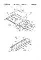
- FIG. 1is a perspective view of an embodiment of the present invention illustrated as an ice pack
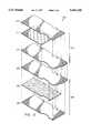
- FIG. 2is an exploded perspective view of an embodiment of the bag from FIG. 1;
- FIG. 3is an exploded perspective view of an alternate embodiment of the bag from FIG. 1;
- FIG. 4is a perspective view of an embodiment of the clip from FIG. 1;
- FIG. 5is a partial side view of the ice pack from FIG. 1, illustrating the bag from FIG. 1 being closed by the clip from FIG. 4;
- FIG. 6is a partial perspective view of the ice pack from FIG. 1, illustrating the bag from FIG. 1 being closed by the clip from FIG. 4;
- FIG. 7is an exploded perspective view of an alternate embodiments of the bag from FIG. 1;
- FIG. 8is an exploded perspective view of an alternate embodiment of the bag from FIG. 1;
- the ice pack 100generally comprises a bag 200, securement devices 310 and 360, and a clip 400.
- the bag 200has a first side wall 210 and a second side wall 220 joined together by a weld 230 to form a containment section 240, a neck 250, a mouth 260, and a clip mounting tab 280.
- the containment section 240is a generally rectangular shape with a bottom 242, a first side 244, and a second side 246.
- the containment section 240can be alternative shapes such as oval or any other shape which can contain the ice and liquids therein.
- the neck 250has a first side 254 and a second side 256 which extend from the sides 244 and 246, respectively, of the containment section 240 to the mouth 260 of the bag 200.
- the first and second side 254 and 256form a passage or throat in the inside of the neck 250 which communicates with the interior of the containment section 240.
- the mouth 260has a first side 264 and a second side 266 which extend from the first and second side 254 and 256 of the neck 250, respectively, to an opening 262.
- the opening 262 of the mouth 260communicates with the interior or throat of the neck 250.
- the mouth 260 of the bag 200also has a first handle 267 and a second handle 268 disposed on the walls 210 and 220, respectively, in the area of the opening 262.
- the clip mounting tab 280is preferably located adjacent to the neck 250.
- the mouth 260has been illustrated herein as larger than the neck 250, in another construction the mouth 260 can be the same size or smaller than the neck 250.
- the containment section 240has been illustrated herein as larger than the neck 250, in yet another construction the containment section 240 can be the same size or smaller than the neck 250.
- FIG. 2there is illustrated an exploded perspective view of an embodiment of the bag 200 from FIG. 1.
- the containment section 240, the neck 250, and the mouth 260 of the bag 200 in FIG. 1are formed by joining the first side wall 210 to the second wall 220 with the weld 230 in FIG. 1.
- the first side wall 210is a multilayered material having a throat element 212, a first layer or insulation layer 214, a waterproof layer 216, and an outer barrier layer 218.
- the second wall 220has a throat element 222, a first layer or insulation layer 224, an waterproof layer 226, and an outer barrier layer 228.
- the throat elements 212 and 222are disposed in the area of the walls 210 and 220, respectively, which form the neck 250 and the mouth 260 of the bag 200 in FIG. 1.
- the throat elements 212 and 222also cover a portion of the walls 210 and 220, respectively, in an upper portion of the containment section 240 of the bag 200 in FIG. 1.
- handles 267 and 268are formed on the throat elements 212 and 222, respectively.
- the throat elements 212 and 222are preferably formed of polyethylene or other waterproof material. However, because the throat elements 212 and 222 do not contact the ice and liquids for an extended period of time, it is not necessary that the throat elements 212 and 222 be formed of a waterproof material.
- the insulation layers 214 and 224are disposed over the throat elements 212 and 222, respectively, in the area of the walls 210 and 220 which form the containment section 240 of the bag 200 in FIG. 1.
- the insulation layers 214 and 224control the heat transfer rate and temperature of the walls 210 and 200.
- the insulation layers 214 and 224are preferably formed of a foam or other insulation material.
- the insulation layers 214 and 224are a closed cell foam perforated with holes. The size and density of the holes in the insulation layers are selected to provide a specific heat transfer rate and select temperature for the walls 210 and 220.
- the size and density of holes in the insulation layer 214are different from the size and density of the holes in the insulation layer 224, thereby causing the first side wall 210 to have a different heat transfer rate and temperature than the second side wall 220.
- only one of the insulation layers 214 and 224 of the walls 210 and 220, respectively,is perforated with holes. The absence of holes in the insulation layer of one of the walls 210 or 220 will cause the wall without holes to transfer heat at a slower rate and have a higher temperature than the other wall.
- the insulation layer 214 of the first side wall 210is a different thickness than the insulation layer 224 of the second side wall 220, thereby causing the first side wall 210 to have a different heat transfer rate and temperature than the second side wall 220.
- the insulation layer 214 of the first side wallhas a different thermal conductivity than the insulation layer 224 of the second side wall 220, thereby causing the first side wall 210 to have a different heat transfer rate and temperature than the second side wall 220.
- the waterproof layers 216 and 226are disposed over the insulation layers 214 and 224, respectively, in the area of the walls 210 and 220 which form the containment section 240 of the bag 200 in FIG. 1.
- the waterproof layers 216 and 226,also cover a portion of the walls 210 and 220, respectively, in a lower portion of the neck 250 of the bag 200 in FIG. 1.
- the waterproof layers 216 and 226are preferably formed of polyethylene or other waterproof material.
- the throat elements 212 and 222overlap with the waterproof layers 216 and 226, respectively in the area of the walls 210 and 220 which form the neck 250.
- the throat elements 212 and 222are sealed to the respective waterproof layers 216 and 226 in this overlapping area of the neck 250 by ultrasonic welding, chemical bonding, or the like. In this manner the throat elements 212 and 222 and the waterproof layers 216 and 226 will contain the ice and liquid inside the bag 200 of FIG. 1.
- the waterproof layers 216 and 226are disposed in an area of the walls 210 and 220, respectively, that covers a sufficient area of the neck 250 that the clip 400 (shown in FIG.
- the throat element 212 and the waterproof layer 216 of the first side wall 210are bonded to the insulation layer 214 of said first side wall 210 in the area which forms the neck 250, and the throat element 222 and the waterproof layer 226 of the second side wall 220 are bonded to the insulation layer 224 of the second side wall 220 in the area which forms the neck 250, thereby containing the ice and liquid inside the bag 200 of FIG. 1.
- the insulation layer 214 of the First side wall 210is bonded to the waterproof layer 216 of the first side wall, thereby regulating the space for ice and liquid to accumulate between the insulation layer 214 and the waterproof layer 216.
- the insulation layer 224 of the second side wall 220is bonded to the waterproof layer 226 of the second side wall 220, thereby regulating the space for ice and liquid to accumulate between the insulation layer 224 and the waterproof layer 226.
- the barrier layers 218 and 228are disposed over the waterproof layers 216 and 226, respectively, in the area of the walls 210 and 220 which form the containment section 240, the neck 250, and the mouth 260, excluding the handles 267 and 268.
- the barrier layers 218 and 228reduce the amount of moist air contacting the waterproof layers, reduce the amount of any moisture which may condense on the waterproof layers from contacting the user, and provide a surface texture for the user which is more pleasant than the waterproof layers.
- the barrier layers 218 and 228are preferably formed of a spun polyester material or the like.
- FIG. 3there is illustrated an exploded perspective view of another construction of the bag 200 from FIG. 1.
- the containment section 240, the neck 250, and the mouth 260 of the bag 200 in FIG. 1are formed by joining the first side wall 210 to the second side wall 220 with the weld 230 in FIG. 1.
- the first side wallcomprises the throat element 212, the first layer or insulation layer 214, the waterproof layer 216, and the barrier layer 218.
- the second side wall 220comprises a waterproof layer 223, a relief layer 225, and the barrier layer 228.
- the waterproof layer 223is disposed in the area of the wall 220 which forms the containment section 240, the neck 250, and the mouth 260 of the bag 200 in FIG. 1. Also, handle 268 is formed on the waterproof layer 223 in the area of the opening 262 of the mouth 260 in FIG. 1 of the bag 200.
- the waterproof layer 223is preferably formed of polyethylene or other waterproof material. In this manner, the waterproof layer 223 combined with the throat element 212 and the waterproof layer 216 will contain the ice and liquid inside the bag 200 of FIG. 1.
- the relief layer 225is disposed over the waterproof layer 213, and in the area of the wall 220 which forms the containment section 240 of the bag 200 in FIG. 1.
- the relief layer 225also covers a portion of the wall 220 in a lower portion of the neck 250 of the bag 200 in FIG. 1.
- the relief layer 225is preferably formed of polyethylene or other material.
- the relief layer 225has a surface texture with many rises and recesses. The rises and recesses of the relief layer 225 reduce the amount of smooth flat surface. Smooth surfaces facilitate the formation and spread of condensation on a layer, while surfaces with relief or texture will retard the spread of condensation. Also, the rises and recesses of the relief layer 225 form air pockets which facilitate insulation of the side wall 220.
- the insulation provide by the relief layer 225controls the heat transfer rate and temperature of the side wall 220.
- the insulation provided by the relief layer 225also helps control the rate at which the side wall 220 initially reaches the desired temperature. By controlling the rate at which the side wall 220 reaches the desired temperature, condensation can be reduced which is caused by the side wall 220 reaching the desired temperature too quickly.
- the rises and recesses of the relief layer 225can be formed by casting, embossing, or other like methods of forming rises and recesses in the relief layer 225.
- the relief layer 225is formed of a material such as "bubble pack", having rises and recesses formed around pockets in the material.
- the barrier layer 228is disposed over the relief layer 225, and in the area of the wall 220 which forms the containment section 240, the neck 250, and the mouth 260, excluding the handle 268.
- the barrier layer 228reduces the amount of moist air contacting the relief layer 225, reduces the amount of any moisture which may condense on the relief layer from contacting the user, and provides a surface texture for the user that is more pleasant that the relief layer 225.
- FIG. 7there is illustrated an exploded perspective view of another construction of the bag 200 from FIG. 1.
- the containment section 240, the neck 250, and the mouth 260 of the bag 200 in FIG. 1are formed by joining the first side wall 210 to the second side wall 220 with the weld 230 in FIG. 1.
- the first side wallcomprises a waterproof layer 213, an insulation layer 215, and the barrier layer 218.
- the second side wall 220comprises the throat element 222, the first layer or insulation layer 224, the waterproof layer 226, and the barrier layer 228, as shown and described in reference to FIG. 2.
- the waterproof layer 213is disposed in the area of the wall 210 which forms the containment section 240, the neck 250, and the mouth 260 of the bag 200 in FIG. 1. Also, handle 267 is formed on the waterproof layer 213 in the area of the opening 262 of the mouth 260 in FIG. 1 of the bag 200.
- the waterproof layer 213is preferably formed of polyethylene or other waterproof material. In this manner, the waterproof layer 213 of the first side wall 210 will act in combination with the throat element 222 and the waterproof layer 226 of the second side wall 220 to contain the ice and liquid inside the bag 200 of FIG. 1.
- the insulation layer 215is disposed over the waterproof layer 213 in the area of the wall 210 which forms the containment section 240 of the bag 200 in FIG. 1.
- the insulation layer 215controls the heat transfer rate and temperature of the wall 210.
- the insulation layer 215is preferably formed of a foam or other insulation material.
- the insulation layer 215is preferably bonded to the waterproof layer 213 over the entire surface of the insulation layer 215; however, the insulation layer 215 can be bonded to the waterproof layer 213 in only select locations, such as the weld 230 in FIG. 1.
- the insulation layer 234is a closed cell foam perforated with holes.
- the size and density of the holes in the insulation layer 215are selected to provide a specific heat transfer rate and select temperature for the wall 210.
- the insulation layer 215is a closed cell foam which is not perforated with holes.
- the thickness of the insulation layer 215is selected to provide a specific the heat transfer rate and temperature for the first side wall 210.
- the thermal conductivity of the insulation layer 215is selected to provide a specific the heat transfer rate and temperature for the first side wall 210.
- the insulation layer 215causes the first side wall 210 to have a different heat transfer rate and temperature than the second side wall 220.
- the barrier layer 218is disposed over the insulation layer 215, and in the area of the wall 210 which forms the containment section 240, the neck 250, and the mouth 260, excluding the handle 267.
- the barrier layer 218reduces the amount of moist air contacting the insulation layer 215, reduces the amount of any moisture which may condense on the insulation layer 215 from contacting the user, and provides a surface texture for the user that is more pleasant that the insulation layer 215.
- FIG. 8there is illustrated an exploded perspective view of another construction of the bag 200 from FIG. 1.
- the containment section 240, the neck 250, and the mouth 260 of the bag 200 in FIG. 1are formed by joining the first side wall 210 to the second side wall 220 with the weld 230 in FIG. 1.
- the first side wallcomprises the waterproof layer 213, the insulation layer 215, and the barrier layer 218, as shown and described in reference to FIG. 7.
- the second side wall 220comprises the waterproof layer 223, the relief layer 225, and the barrier layer 228, as shown and described in reference to FIG. 3.
- the layers of the walls 210 and 220are positioned and trimmed to the desired shape of the bag 200.
- a section of the materialis left with the walls 210 and 220 near the throat 256 of the neck 250 for forming the clip mounting tab 280.
- the positioned and trimmed layers of the walls 210 and 220are then bonded together by the weld 230.
- the weld 230progresses around the walls 210 and 220 to form the containment section 240, the neck 250, and the mouth 260 of the bag 200.
- the weld 230can be a sonic weld, heat weld, or bonding method, such as glue, or the like.
- the layers of the walls 210 and 220are bonded together in the area of the of the clip mounting tab 280 by sonic welding, heat welding, or chemical bonding, or the like.
- the clip mounting tab 280presents a surface which facilitates mounting the clip 400 thereon.
- the clip mounting tab 280has been illustrated as being an integral part of the walls 210 and 220, the clip mounting tab 280 could be a separate component which is mounted to the walls 210 and 220 of the bag 200.
- the clip mounting tab 280is illustrated as being positioned on the side of the neck 250, the clip mounting tab 280 could be located on any area of the bag 200.
- the securement devices 310 and 360each include a hook strip 320 and 370, respectively, and a pile strap 330 and 380, respectively.
- the hook strips 320 and 370have hook surfaces 325 and 375, respectively, which are a closely spaced apart multiplicity of hook-like members.
- the pile straps 330 and 380have pile surfaces 335 and 385 with loose loops of filament fibers which are designed to cooperate with the hooks in the hook surfaces 325 and 375 in the hook strips 320 and 370, respectively.
- the hook strip 320is mounted on the first wall 210 near the bottom 242 of the containment section 240, with the hook surface 325 facing away from the first wall 210.
- the pile strap 330is mounted on the second wall 220 near the bottom 242 of the containment section 240, with the pile surface 335 facing away from the second wall 220.
- the pile strap 330has a sufficient length to pass around an object that the ice pack 100 is to be applied, and engage the hook strip 320.
- the hook strip 370is mounted on the first wall 210 near the intersection of the containment section 240 and the neck 250, with the hook surface 375 facing away from the wall 210.
- the pile strap 380is mounted on the second wall 220 near the intersection of the containment section 240 and the neck 250, with the pile surface 385 facing away from the second wall 220.
- the pile strap 380has a sufficient length to pass around an object that the ice pack 100 is to be applied, and engage the hook strip 370.
- the securement device 310has been illustrated with the hook strip 320 mounted to the first wall 210 and the pile strap 330 mounted to the second wall 220, the hook strip 320 can be mounted to the second wall 220 and the pile strap 330 mounted to the first wall 210, or both the hook strip 320 and the pile strap can be mounted to the same wall of the bag 200.
- the hook strip 370can be mounted to the second wall 220 and the pile strap 330 mounted to the first wall 210, or both the hook strip 370 and the pile strap 330 can be mounted to the same wall of the bag 200.
- the securement devices 310 and 360have been illustrated as members of a hook and pile fastener, any other similar engaging means can be used such as buttons, snaps, or the like.
- the clip 400generally comprises a first plate 410 pivotally connected to a second plate 420 by a hinge 430.
- the clip 400can be formed of a resilient plastic, or the like.
- the first plate 410 and the second plate 420have an inner surface 412 and an inner surface 422, respectively.
- the first plate 410 and the second plate 420are connected to the hinge 430 such that the inner surface 412 of the first plate 410 rotates to face the inner surface 422 of the second plate 420.
- an elongated hook 450extends outwardly from the inner surface 412 of the first plate 410.
- an elongated hook 460extends outwardly from the inner surface 422 of the second plate 420.
- the elongated hook 450 and the elongated hook 460are positioned on the first plate 410 and the second plate 420, respectively, such that when the first plate 410 and the second plate 420 are rotated towards each other about the hinge 430, the elongated hook 450 and the elongated hook 460 engage.
- the elongated hooks 450 and 460can also be located on the first plate 410 and the second plate 420, respectively, such that grip portions 470 and 480 of the first plate 410 and the second plate 420, respectively, provide sufficient area for a user to grasp the handles 470 and 480 for opening the clip 400.
- FIG. 1 and FIG. 4it can be seen how the clip 400 attaches to the bag 200.
- the clip mounting tab 280 of the bag 200is positioned on the inner surfaces 412 and 422 of the clip 400 so that the neck 250 of the bag 200 is centered within the clip 400.
- the clip 400is attached to the clip mounting tab 280 of the bag 200 by sonic welding, hot glue, bonding, an adhesive strip, a fastener, or the like.
- the ice pack 100has been illustrated with the clip 400 attached to the clip mounting tab 280 of the bag 200, the clip 400 could also be attached directly to any portion of the walls 210 and 220 in the area of the neck 250.
- the bag 200is illustrated as being attached to the inner surfaces 412 and 422 of the clip 400, the bag 200 could be attached to any area of the clip 400.
- the clip 400could be attached to the bag 200 by tape or a similar means for attaching.
- FIG. 5there is shown a partial side view of the ice pack 100 from FIG. 1, illustrating the bag 200 being closed by the clip 400.
- the first plate 410 and the second plate 420 of the clip 400are rotated to a position where the elongated hooks 450 and 460 are engaged.
- the walls 210 and 220 of the bag 200are folded over in the area of the neck 250 and are positioned between the elongated hooks 450 and 460 of the clip 400.
- the force of the elongated hooks 450 and 460 engaging each otherwill apply a force to the exterior of the walls 210 and 220 of the bag 200, which will force the interior surfaces of the walls 210 and 220 together and prevent ice and liquids in the containment section 240 of the bag 200, in FIG. 1, from escaping through the neck 250 and the mouth 260 of the bag 200.
- FIG. 6there is shown a partial perspective view of the ice pack 100 from FIG. 1, illustrating the bag 200 being closed by the clip 400.
- the first plate 410 and the second plate 420 of the clip 400are contoured at a first end 470 and a second end 480 of the clip 400.
- the contour of the first plate 410 and the second plate 420is such that sharp corners are reduced at the first end 470 and the second end 480 of the clip 400 when the clip 400 is in the closed position. The reduction of sharp corners on the clip 400 prevents injury to the user.
- FIGS. 1-8it can be seen how the ice pack 100 of the present invention is utilized. Ice is inserted into the bag 200 through the opening 262 in the mouth 260 of the bag 200.
- the throat elements 212 and 222extend below the insulation layers 214 and 222 into the containment section 240 of the bag 200, thereby allowing ice and liquids pass into the containment section 240 of the bag 200 without obstruction by the insulation layers 214 and 224.
- any air in the containment section 240can be kneaded out through the opening 262 in the mouth 260 of the bag 200.
- the neck 250 of the bag 200is positioned completely within the clip 400 by gently pressing the neck 250 of the bag 200 in between the elongated hooks 450 and 460 of the clip 400.
- the first plate 410 and the second plate 420are rotated about the hinge 430 until the elongated hooks 450 and 460 engage, thereby securing the neck 250 of the bag 200 therebetween.
- the clip 400will secure the layers of the ice pack together at the neck 250 and prevent the escape of ice and liquids within the containment section 240 of the bag 200.
- the neck 250 of the bag 200is not positioned completely within the clip 400, the user will be alerted to the improper interface by the difficulty of closing the clip 400, or the obscure angle of the clip 400 relative to the neck 250 of the bag 200.
- the containment portion 240 of the bag 200 containing the icecan be placed against the location which is desired to cool.
- the usercan apply either the first side wall 210 of the bag 200 against the surface to be cooled, or the second side wall 220 of the bag 200 against the surface to be cooled, depending on the degree of heat transfer and temperature difference which is desired by the user. Liquids inserted into the bag 200 with the ice, or from the melting of the ice, will pass through the holes perforated in the insulation layers 214 and 224 of the walls 210 and 220.
- a pocket of liquidwill form in between the insulation layer 214 and the waterproof layer 216 of the first wall 210, and in between the insulation layer 224 and the waterproof layer 226 of the second wall 220. These pockets of liquid facilitate the transfer of heat and reduce temperature gradients, or hot and cold "spots" across the surface of the first side wall 210 or the second side wall 220.
- the ice pack 100is secured to an object by wrapping the pile straps 330 and 380 around the object and fastening the pile straps 330 and 380 to the first side hook strips 320 and 370, respectively. Because the pile straps 330 and 380 fasten to the hook strips 320 and 370 simply by applying a slight pressure, the user will be able to secure the ice pack 100 with only one free hand. In contrast, the prior art devices are secured by tying a knot in a pair of straps, which requires the use of both hands. Therefore, a user will need assistance from another person to secure the prior art device ice pack to an area of the body such as an arm. The improvement of securement devices 310 and 360 will allow a user to apply and adjust the ice pack 100 on an area, such as an arm, without assistance from another person.
- the ice pack 100can be opened by pulling the mouth 240 of the bag 200 away from the containment section 240 of the bag 200. This will force the elongated hooks 450 and 460 of the clip 400 to separate, and allow the neck 250 of the bag 200 to open. After the bag 200 has been opened, the ice and liquids can be removed from the ice pack 100 through the opening 262 in the mouth 260 of the bag 200, and the ice pack 100 can be discarded or saved for later use.
- the multilayered bag described hereincan be used without a clip, or with any type of clip, or without the clip mounting tab.
- the clip mounting tab described hereincan be used with any type of bag or with any type of clip.
- the clip described hereincan be used with any type of bag, or without the clip mounting tab.
- the securement devices described hereincan be used with any type of bag and without the clip. Therefore, the spirit and scope of the appended claims should not be limited to the description of the preferred embodiments contained herein.
Landscapes
- Health & Medical Sciences (AREA)
- Vascular Medicine (AREA)
- Thermal Sciences (AREA)
- Engineering & Computer Science (AREA)
- Biomedical Technology (AREA)
- Heart & Thoracic Surgery (AREA)
- Physics & Mathematics (AREA)
- Life Sciences & Earth Sciences (AREA)
- Animal Behavior & Ethology (AREA)
- General Health & Medical Sciences (AREA)
- Public Health (AREA)
- Veterinary Medicine (AREA)
- Packages (AREA)
Abstract
Description
This application is a continuation-in-part of application Ser. No. 08/294,142, filed Aug. 22, 1994, pending, which is a continuation-in-part of application Ser. No. 08/045,360, filed Apr. 13, 1993, now U.S. Pat. No. 5,356,426.
1. Field of the Invention
The present invention relates to ice packs, and more particularly to ice packs with a bag, a closure component, and components for securing the ice pack.
2. Description of the Related Art
Ice packs are used for cooling various surfaces such as cooling a portion of a patient's body for medical reasons. Ice packs generally have a bag with a containment section, a neck, and a mouth. Ice is inserted into the containment section of the bag through the mouth and neck of the bag. Once ice is inserted into the containment section of the bag, a closure component seals the containment section of the bag and the ice pack is applied to the desired location.
Ice in the containment section of the bag reduces the temperature of the bag for the intended use of the ice pack. However, temperature gradients can exist across the surface of the bag due to the concentration of ice in different areas in the containment section of the bag. Also, it would be an advantage to control the rate at which heat is transferred at the surface of the bag, and to control the temperature of the outer surface of the bag. Therefore, it would be an advantage to provide an ice pack with a bag that can reduce temperature gradients across the surface of the bag, help control the rate of heat exchange at the surface of the bag, and help control the temperature of the outer surface of the bag.
Once the ice has been inserted into the containment section of the bag, it is preferred that the containment section be closed off so that the ice and liquid in the containment section will not run out of the ice pack. Some of the closure components in used prior art ice packs to close off the containment section of a bag include such items as stoppers, clips, etc.
Generally, stoppers block the opening in neck of the bag, thereby preventing ice and liquids from escaping from the containment section of the bag. However, stoppers require a bag with a neck specifically designed for use with the stopper.
In contrast, clips do not require the neck portion of a bag to be specifically designed for use with the clip. A clip closes off the containment section of a bag by applying force to the external surfaces of the neck. The forces on the external surfaces of the neck force together the internal surfaces of the neck, thereby closing off the containment section of the bag.
Because the clip is a separate component from the bag of an ice pack, it is desirous to attach the clip to the bag. Attaching the clip to the bag prevents the loss of the clip, and searching to find a clip each time a ice pack is used. Typically, the clip will be attached to the bag at the location on the neck which the clip is intended to engage and seal.
However, various types of prior art clips, and the method of attaching those clips, are such that it is possible to close the clip without securing and sealing the neck of the ice bag. Therefore, there is a need for an ice pack having a clip which will facilitate closing the clip with the neck of the bag engaged in, and sealed by, the clip.
After the bag of the ice pack has been filled with ice and closed off by a closure component, the ice pack is applied to the desired surface. In prior art ice packs, tie strings have been attached to the bag in a longitudinal direction. The tie strings are wrapped around the object on which the ice pack is applied, and a knot is tied in the tie strings to secure the ice pack thereon.
However, it is difficult for a user to tie a knot in the tie strings when the user is applying the ice pack to the user's own body. Also, it is difficult to adjust the firmness with which the tie strings secure the ice pack to the applied area. Therefore, there is a need for an ice pack which can be easily attached and adjusted on the object being cooled.
In one embodiment, the present invention is an ice pack which includes a bag having a first side wall welded to a second side wall to form a containment section, a neck, and a mouth. In one aspect, a first side wall includes a waterproof layer disposed in the area of the first side wall which forms the containment section, the neck, and the mouth, and includes an insulation layer disposed over the waterproof layer and in the area of the first side wall which forms the containment section of the bag. In a further aspect, a second side wall includes: a throat piece disposed in the area of the second side wall which forms the mouth, the neck, and an upper portion of the containment section; an insulation layer disposed over the throat piece and in the area of the second side wall which forms the containment section; and a waterproof layer disposed over the insulation layer and in the area of the second side wall which forms the containment section and an upper portion of the neck. In another further aspect, a second wall includes a waterproof layer disposed in the area of the second side wall which forms the containment section, the neck, and the mouth, and includes a relief layer disposed over the waterproof layer and in the area of the second side wall which forms the containment section. In another aspect, the side walls have an insulation layer disposed inside of a waterproof layer. In another aspect, the side walls have a throat element disposed in the area of the walls which form the neck and an upper portion of the containment section, an insulation layer disposed in the area of the walls which forms the containment section, and a waterproof layer disposed in the area of the walls which form the containment section and a lower portion of the neck. In a further aspect, the insulation layer in one of the walls is perforated with a plurality of holes. In yet a further aspect, the insulation layer in both walls is perforated with a plurality of holes. In yet a further aspect, the holes in the insulation layer of one of the walls is larger than the holes in the insulation layer of the other wall. In another further aspect, the insulation layer of one of the walls has more holes per square area than the insulation layer of the other wall. In another aspect, each of the walls includes a barrier layer which is disposed over the waterproof layer and in the area of the walls which forms the containment section and the neck section. In another aspect, the bag includes a mouth having a first handle which is formed in one of the side walls, and a second handle which is formed in the other side wall.
In another embodiment, the present invention includes a bag having a containment section, a neck, a mouth, and a clip. The clip has a first plate connected to a second plate by a hinge so that an inner surface of the first plate rotates toward an inner surface of the second plate. The clip also has a first elongated hook and a second elongated hook extending from the inner surfaces of the first plate and the second plate, respectively, so that the first elongated hook engages and secures with the second elongated hook when the inner surfaces of the first plate and the second plate are rotated towards each other. The neck of the bag is secured between the engaged first and second elongated hooks, thereby sealing the bag. In a further aspect, the clip is attached to the bag of the ice pack. In yet a further aspect, the inside surface of the first plate of the clip is attached to the neck of the bag.
In another embodiment, the present invention includes a bag having a containment section, a neck, a clip mounting tab, and a clip for securing the neck of the bag closed. The clip is attached to the clip mounting tab of the bag. In a further aspect, the bag has a clip mounting tab which is attached to the clip. In yet a further aspect, the clip mounting tab is mounted to the inside surface of the first plate of the clip.
In another embodiment, the present invention includes a bag having a first securement device. The first securement device has a first means for engaging mounted on the bag, a strap attached to the bag, and a second means for engaging mounted on the strap. The second means for engaging is adapted to engage with and secure to the first means for engaging. In a further aspect, the present invention includes a second securement device having a first means for engaging mounted to the bag, a strap attached to the bag, and second means for engaging mounted to the strap and adapted to engage and secure with the first means for attaching of the second securement device. In yet a further aspect of the invention, the first means for attaching and the second means for attaching of the first securement device are components of a hook and pile type fastener. In yet a further aspect of the present invention, the first means for attaching and the second means for attaching of the second securement device are components of a hook and pile type fastener.
For a more complete understanding of the present invention, and for further objectives and advantages thereof, reference may now be taken in conjunction with the accompanying drawings herein:
FIG. 1 is a perspective view of an embodiment of the present invention illustrated as an ice pack;
FIG. 2 is an exploded perspective view of an embodiment of the bag from FIG. 1;
FIG. 3 is an exploded perspective view of an alternate embodiment of the bag from FIG. 1;
FIG. 4 is a perspective view of an embodiment of the clip from FIG. 1;
FIG. 5 is a partial side view of the ice pack from FIG. 1, illustrating the bag from FIG. 1 being closed by the clip from FIG. 4;
FIG. 6 is a partial perspective view of the ice pack from FIG. 1, illustrating the bag from FIG. 1 being closed by the clip from FIG. 4; and
FIG. 7 is an exploded perspective view of an alternate embodiments of the bag from FIG. 1;
FIG. 8 is an exploded perspective view of an alternate embodiment of the bag from FIG. 1;
Referring first to FIG. 1, there is shown a perspective view of an embodiment of the present invention, illustrated as anice pack 100. Theice pack 100 generally comprises abag 200,securement devices clip 400.
Still referring to FIG. 1, thebag 200 has afirst side wall 210 and asecond side wall 220 joined together by aweld 230 to form acontainment section 240, aneck 250, amouth 260, and aclip mounting tab 280. As illustrated, thecontainment section 240 is a generally rectangular shape with a bottom 242, afirst side 244, and asecond side 246. However, thecontainment section 240 can be alternative shapes such as oval or any other shape which can contain the ice and liquids therein. Theneck 250 has afirst side 254 and asecond side 256 which extend from thesides containment section 240 to themouth 260 of thebag 200. The first andsecond side neck 250 which communicates with the interior of thecontainment section 240. Themouth 260 has afirst side 264 and asecond side 266 which extend from the first andsecond side neck 250, respectively, to anopening 262. Theopening 262 of themouth 260 communicates with the interior or throat of theneck 250. Themouth 260 of thebag 200 also has afirst handle 267 and asecond handle 268 disposed on thewalls opening 262. Theclip mounting tab 280 is preferably located adjacent to theneck 250. Although themouth 260 has been illustrated herein as larger than theneck 250, in another construction themouth 260 can be the same size or smaller than theneck 250. Furthermore, although thecontainment section 240 has been illustrated herein as larger than theneck 250, in yet another construction thecontainment section 240 can be the same size or smaller than theneck 250.
Referring now to FIG. 2, there is illustrated an exploded perspective view of an embodiment of thebag 200 from FIG. 1. Thecontainment section 240, theneck 250, and themouth 260 of thebag 200 in FIG. 1 are formed by joining thefirst side wall 210 to thesecond wall 220 with theweld 230 in FIG. 1. Thefirst side wall 210 is a multilayered material having athroat element 212, a first layer orinsulation layer 214, awaterproof layer 216, and anouter barrier layer 218. Likewise, thesecond wall 220 has athroat element 222, a first layer orinsulation layer 224, anwaterproof layer 226, and anouter barrier layer 228.
Still referring to FIG. 2, thethroat elements walls neck 250 and themouth 260 of thebag 200 in FIG. 1. Thethroat elements walls containment section 240 of thebag 200 in FIG. 1. Also, handles 267 and 268 are formed on thethroat elements throat elements throat elements throat elements
Referring still to FIG. 2, the insulation layers 214 and 224 are disposed over thethroat elements walls containment section 240 of thebag 200 in FIG. 1. The insulation layers 214 and 224 control the heat transfer rate and temperature of thewalls walls insulation layer 214 are different from the size and density of the holes in theinsulation layer 224, thereby causing thefirst side wall 210 to have a different heat transfer rate and temperature than thesecond side wall 220. In another construction, only one of the insulation layers 214 and 224 of thewalls walls insulation layer 214 of thefirst side wall 210 is a different thickness than theinsulation layer 224 of thesecond side wall 220, thereby causing thefirst side wall 210 to have a different heat transfer rate and temperature than thesecond side wall 220. In yet another construction, theinsulation layer 214 of the first side wall has a different thermal conductivity than theinsulation layer 224 of thesecond side wall 220, thereby causing thefirst side wall 210 to have a different heat transfer rate and temperature than thesecond side wall 220.
Still referring to FIG. 2, thewaterproof layers walls containment section 240 of thebag 200 in FIG. 1. Thewaterproof layers walls neck 250 of thebag 200 in FIG. 1. Thewaterproof layers
Referring still to FIG. 2, it can be seen that in the area of theneck 250, thethroat elements waterproof layers walls neck 250. Thethroat elements waterproof layers neck 250 by ultrasonic welding, chemical bonding, or the like. In this manner thethroat elements waterproof layers bag 200 of FIG. 1. In another construction, thewaterproof layers walls neck 250 that the clip 400 (shown in FIG. 1) will seal thewaterproof layers throat element 212 and thewaterproof layer 216 of thefirst side wall 210 are bonded to theinsulation layer 214 of saidfirst side wall 210 in the area which forms theneck 250, and thethroat element 222 and thewaterproof layer 226 of thesecond side wall 220 are bonded to theinsulation layer 224 of thesecond side wall 220 in the area which forms theneck 250, thereby containing the ice and liquid inside thebag 200 of FIG. 1. In another construction, theinsulation layer 214 of theFirst side wall 210 is bonded to thewaterproof layer 216 of the first side wall, thereby regulating the space for ice and liquid to accumulate between theinsulation layer 214 and thewaterproof layer 216. In yet another construction, theinsulation layer 224 of thesecond side wall 220 is bonded to thewaterproof layer 226 of thesecond side wall 220, thereby regulating the space for ice and liquid to accumulate between theinsulation layer 224 and thewaterproof layer 226.
Still referring to FIG. 2, the barrier layers 218 and 228 are disposed over thewaterproof layers walls containment section 240, theneck 250, and themouth 260, excluding thehandles
Referring now to FIG. 3, there is illustrated an exploded perspective view of another construction of thebag 200 from FIG. 1. Thecontainment section 240, theneck 250, and themouth 260 of thebag 200 in FIG. 1 are formed by joining thefirst side wall 210 to thesecond side wall 220 with theweld 230 in FIG. 1. As previously shown in reference to FIG. 2, the first side wall comprises thethroat element 212, the first layer orinsulation layer 214, thewaterproof layer 216, and thebarrier layer 218. However, thesecond side wall 220 comprises awaterproof layer 223, arelief layer 225, and thebarrier layer 228.
Still referring to FIG. 3, thewaterproof layer 223 is disposed in the area of thewall 220 which forms thecontainment section 240, theneck 250, and themouth 260 of thebag 200 in FIG. 1. Also, handle 268 is formed on thewaterproof layer 223 in the area of theopening 262 of themouth 260 in FIG. 1 of thebag 200. Thewaterproof layer 223 is preferably formed of polyethylene or other waterproof material. In this manner, thewaterproof layer 223 combined with thethroat element 212 and thewaterproof layer 216 will contain the ice and liquid inside thebag 200 of FIG. 1.
Referring still to FIG. 3, therelief layer 225 is disposed over thewaterproof layer 213, and in the area of thewall 220 which forms thecontainment section 240 of thebag 200 in FIG. 1. Therelief layer 225 also covers a portion of thewall 220 in a lower portion of theneck 250 of thebag 200 in FIG. 1. Therelief layer 225 is preferably formed of polyethylene or other material. Therelief layer 225 has a surface texture with many rises and recesses. The rises and recesses of therelief layer 225 reduce the amount of smooth flat surface. Smooth surfaces facilitate the formation and spread of condensation on a layer, while surfaces with relief or texture will retard the spread of condensation. Also, the rises and recesses of therelief layer 225 form air pockets which facilitate insulation of theside wall 220. The insulation provide by therelief layer 225 controls the heat transfer rate and temperature of theside wall 220. The insulation provided by therelief layer 225 also helps control the rate at which theside wall 220 initially reaches the desired temperature. By controlling the rate at which theside wall 220 reaches the desired temperature, condensation can be reduced which is caused by theside wall 220 reaching the desired temperature too quickly. The rises and recesses of therelief layer 225 can be formed by casting, embossing, or other like methods of forming rises and recesses in therelief layer 225. Alternatively, therelief layer 225 is formed of a material such as "bubble pack", having rises and recesses formed around pockets in the material.
Still referring to FIG. 3, thebarrier layer 228 is disposed over therelief layer 225, and in the area of thewall 220 which forms thecontainment section 240, theneck 250, and themouth 260, excluding thehandle 268. Thebarrier layer 228 reduces the amount of moist air contacting therelief layer 225, reduces the amount of any moisture which may condense on the relief layer from contacting the user, and provides a surface texture for the user that is more pleasant that therelief layer 225.
Referring now to FIG. 7, there is illustrated an exploded perspective view of another construction of thebag 200 from FIG. 1. Thecontainment section 240, theneck 250, and themouth 260 of thebag 200 in FIG. 1 are formed by joining thefirst side wall 210 to thesecond side wall 220 with theweld 230 in FIG. 1. The first side wall comprises awaterproof layer 213, aninsulation layer 215, and thebarrier layer 218. Thesecond side wall 220 comprises thethroat element 222, the first layer orinsulation layer 224, thewaterproof layer 226, and thebarrier layer 228, as shown and described in reference to FIG. 2.
Still referring to FIG. 7, thewaterproof layer 213 is disposed in the area of thewall 210 which forms thecontainment section 240, theneck 250, and themouth 260 of thebag 200 in FIG. 1. Also, handle 267 is formed on thewaterproof layer 213 in the area of theopening 262 of themouth 260 in FIG. 1 of thebag 200. Thewaterproof layer 213 is preferably formed of polyethylene or other waterproof material. In this manner, thewaterproof layer 213 of thefirst side wall 210 will act in combination with thethroat element 222 and thewaterproof layer 226 of thesecond side wall 220 to contain the ice and liquid inside thebag 200 of FIG. 1.
Referring still to FIG. 7, theinsulation layer 215 is disposed over thewaterproof layer 213 in the area of thewall 210 which forms thecontainment section 240 of thebag 200 in FIG. 1. Theinsulation layer 215 controls the heat transfer rate and temperature of thewall 210. Theinsulation layer 215 is preferably formed of a foam or other insulation material. Theinsulation layer 215 is preferably bonded to thewaterproof layer 213 over the entire surface of theinsulation layer 215; however, theinsulation layer 215 can be bonded to thewaterproof layer 213 in only select locations, such as theweld 230 in FIG. 1. In the illustrated embodiment of the invention, the insulation layer 234 is a closed cell foam perforated with holes. The size and density of the holes in theinsulation layer 215 are selected to provide a specific heat transfer rate and select temperature for thewall 210. In another construction, theinsulation layer 215 is a closed cell foam which is not perforated with holes. In yet another construction, the thickness of theinsulation layer 215 is selected to provide a specific the heat transfer rate and temperature for thefirst side wall 210. In yet another construction, the thermal conductivity of theinsulation layer 215 is selected to provide a specific the heat transfer rate and temperature for thefirst side wall 210. Preferably, theinsulation layer 215 causes thefirst side wall 210 to have a different heat transfer rate and temperature than thesecond side wall 220.
Still referring to FIG. 7, thebarrier layer 218 is disposed over theinsulation layer 215, and in the area of thewall 210 which forms thecontainment section 240, theneck 250, and themouth 260, excluding thehandle 267. Thebarrier layer 218 reduces the amount of moist air contacting theinsulation layer 215, reduces the amount of any moisture which may condense on theinsulation layer 215 from contacting the user, and provides a surface texture for the user that is more pleasant that theinsulation layer 215.
Referring now to FIG. 8, there is illustrated an exploded perspective view of another construction of thebag 200 from FIG. 1. Thecontainment section 240, theneck 250, and themouth 260 of thebag 200 in FIG. 1 are formed by joining thefirst side wall 210 to thesecond side wall 220 with theweld 230 in FIG. 1. The first side wall comprises thewaterproof layer 213, theinsulation layer 215, and thebarrier layer 218, as shown and described in reference to FIG. 7. Thesecond side wall 220 comprises thewaterproof layer 223, therelief layer 225, and thebarrier layer 228, as shown and described in reference to FIG. 3.
Referring now to FIGS. 1, 2, 3, 7, and 8 in combination, it can be seen how thebag 200 is formed. The layers of thewalls bag 200. In the process of trimming thewalls walls throat 256 of theneck 250 for forming theclip mounting tab 280. The positioned and trimmed layers of thewalls weld 230. Theweld 230 progresses around thewalls containment section 240, theneck 250, and themouth 260 of thebag 200. Theweld 230 can be a sonic weld, heat weld, or bonding method, such as glue, or the like.
Still referring to FIGS. 1, 2, 3, 7 and 8 in combination, the layers of thewalls clip mounting tab 280 by sonic welding, heat welding, or chemical bonding, or the like. By bonding the layers of thewalls clip mounting tab 280 presents a surface which facilitates mounting theclip 400 thereon. Although theclip mounting tab 280 has been illustrated as being an integral part of thewalls clip mounting tab 280 could be a separate component which is mounted to thewalls bag 200. Furthermore, although theclip mounting tab 280 is illustrated as being positioned on the side of theneck 250, theclip mounting tab 280 could be located on any area of thebag 200.
Referring back now to FIG. 1, thesecurement devices hook strip pile strap hook surfaces pile surfaces
Still referring back to FIG. 1, thehook strip 320 is mounted on thefirst wall 210 near thebottom 242 of thecontainment section 240, with thehook surface 325 facing away from thefirst wall 210. Thepile strap 330 is mounted on thesecond wall 220 near thebottom 242 of thecontainment section 240, with thepile surface 335 facing away from thesecond wall 220. Thepile strap 330 has a sufficient length to pass around an object that theice pack 100 is to be applied, and engage thehook strip 320.
Referring back still to FIG. 1, thehook strip 370 is mounted on thefirst wall 210 near the intersection of thecontainment section 240 and theneck 250, with thehook surface 375 facing away from thewall 210. Thepile strap 380 is mounted on thesecond wall 220 near the intersection of thecontainment section 240 and theneck 250, with thepile surface 385 facing away from thesecond wall 220. Thepile strap 380 has a sufficient length to pass around an object that theice pack 100 is to be applied, and engage thehook strip 370.
Still referring back to FIG. 1, although thesecurement device 310 has been illustrated with thehook strip 320 mounted to thefirst wall 210 and thepile strap 330 mounted to thesecond wall 220, thehook strip 320 can be mounted to thesecond wall 220 and thepile strap 330 mounted to thefirst wall 210, or both thehook strip 320 and the pile strap can be mounted to the same wall of thebag 200. Similarly, thehook strip 370 can be mounted to thesecond wall 220 and thepile strap 330 mounted to thefirst wall 210, or both thehook strip 370 and thepile strap 330 can be mounted to the same wall of thebag 200. Also, although thesecurement devices
Referring now to FIG. 4, there is shown a perspective view of an embodiment of theclip 400 from FIG. 1. Theclip 400 generally comprises afirst plate 410 pivotally connected to asecond plate 420 by ahinge 430. Theclip 400 can be formed of a resilient plastic, or the like. Thefirst plate 410 and thesecond plate 420 have aninner surface 412 and aninner surface 422, respectively. Thefirst plate 410 and thesecond plate 420 are connected to thehinge 430 such that theinner surface 412 of thefirst plate 410 rotates to face theinner surface 422 of thesecond plate 420.
Referring still to FIG. 4, anelongated hook 450 extends outwardly from theinner surface 412 of thefirst plate 410. Likewise, anelongated hook 460 extends outwardly from theinner surface 422 of thesecond plate 420. Theelongated hook 450 and theelongated hook 460 are positioned on thefirst plate 410 and thesecond plate 420, respectively, such that when thefirst plate 410 and thesecond plate 420 are rotated towards each other about thehinge 430, theelongated hook 450 and theelongated hook 460 engage. The elongated hooks 450 and 460 can also be located on thefirst plate 410 and thesecond plate 420, respectively, such thatgrip portions first plate 410 and thesecond plate 420, respectively, provide sufficient area for a user to grasp thehandles clip 400.
Referring now to FIG. 1 and FIG. 4 in combination, it can be seen how theclip 400 attaches to thebag 200. Theclip mounting tab 280 of thebag 200 is positioned on theinner surfaces clip 400 so that theneck 250 of thebag 200 is centered within theclip 400. After positioning theclip 400, theclip 400 is attached to theclip mounting tab 280 of thebag 200 by sonic welding, hot glue, bonding, an adhesive strip, a fastener, or the like. Although theice pack 100 has been illustrated with theclip 400 attached to theclip mounting tab 280 of thebag 200, theclip 400 could also be attached directly to any portion of thewalls neck 250. Furthermore, although thebag 200 is illustrated as being attached to theinner surfaces clip 400, thebag 200 could be attached to any area of theclip 400. In another construction, theclip 400 could be attached to thebag 200 by tape or a similar means for attaching.
Referring now to FIG. 5, there is shown a partial side view of theice pack 100 from FIG. 1, illustrating thebag 200 being closed by theclip 400. As illustrated, thefirst plate 410 and thesecond plate 420 of theclip 400 are rotated to a position where theelongated hooks walls bag 200 are folded over in the area of theneck 250 and are positioned between theelongated hooks clip 400. The force of theelongated hooks walls bag 200, which will force the interior surfaces of thewalls containment section 240 of thebag 200, in FIG. 1, from escaping through theneck 250 and themouth 260 of thebag 200.
Referring now to FIG. 6, there is shown a partial perspective view of theice pack 100 from FIG. 1, illustrating thebag 200 being closed by theclip 400. As illustrated, thefirst plate 410 and thesecond plate 420 of theclip 400 are contoured at afirst end 470 and asecond end 480 of theclip 400. The contour of thefirst plate 410 and thesecond plate 420 is such that sharp corners are reduced at thefirst end 470 and thesecond end 480 of theclip 400 when theclip 400 is in the closed position. The reduction of sharp corners on theclip 400 prevents injury to the user.
Referring now to FIGS. 1-8 in combination, it can be seen how theice pack 100 of the present invention is utilized. Ice is inserted into thebag 200 through theopening 262 in themouth 260 of thebag 200. Thethroat elements containment section 240 of thebag 200, thereby allowing ice and liquids pass into thecontainment section 240 of thebag 200 without obstruction by the insulation layers 214 and 224. After sufficient ice is placed within thecontainment section 240 of thebag 200, any air in thecontainment section 240 can be kneaded out through theopening 262 in themouth 260 of thebag 200.
Still referring to FIGS. 1-8 in combination, theneck 250 of thebag 200 is positioned completely within theclip 400 by gently pressing theneck 250 of thebag 200 in between theelongated hooks clip 400. Once theneck 250 of thebag 200 is positioned within theclip 400, thefirst plate 410 and thesecond plate 420 are rotated about thehinge 430 until theelongated hooks neck 250 of thebag 200 therebetween. In this manner, theclip 400 will secure the layers of the ice pack together at theneck 250 and prevent the escape of ice and liquids within thecontainment section 240 of thebag 200. However, if theneck 250 of thebag 200 is not positioned completely within theclip 400, the user will be alerted to the improper interface by the difficulty of closing theclip 400, or the obscure angle of theclip 400 relative to theneck 250 of thebag 200.
Referring still to FIGS. 1-8 in combination, thecontainment portion 240 of thebag 200 containing the ice can be placed against the location which is desired to cool. The user can apply either thefirst side wall 210 of thebag 200 against the surface to be cooled, or thesecond side wall 220 of thebag 200 against the surface to be cooled, depending on the degree of heat transfer and temperature difference which is desired by the user. Liquids inserted into thebag 200 with the ice, or from the melting of the ice, will pass through the holes perforated in the insulation layers 214 and 224 of thewalls insulation layer 214 and thewaterproof layer 216 of thefirst wall 210, and in between theinsulation layer 224 and thewaterproof layer 226 of thesecond wall 220. These pockets of liquid facilitate the transfer of heat and reduce temperature gradients, or hot and cold "spots" across the surface of thefirst side wall 210 or thesecond side wall 220.
Still referring to FIGS. 1-8 in combination, theice pack 100 is secured to an object by wrapping the pile straps 330 and 380 around the object and fastening the pile straps 330 and 380 to the first side hook strips 320 and 370, respectively. Because the pile straps 330 and 380 fasten to the hook strips 320 and 370 simply by applying a slight pressure, the user will be able to secure theice pack 100 with only one free hand. In contrast, the prior art devices are secured by tying a knot in a pair of straps, which requires the use of both hands. Therefore, a user will need assistance from another person to secure the prior art device ice pack to an area of the body such as an arm. The improvement ofsecurement devices ice pack 100 on an area, such as an arm, without assistance from another person.
Referring still to FIGS. 1-8 in combination, once the user is finished with using theice pack 100, theice pack 100 can be opened by pulling themouth 240 of thebag 200 away from thecontainment section 240 of thebag 200. This will force theelongated hooks clip 400 to separate, and allow theneck 250 of thebag 200 to open. After thebag 200 has been opened, the ice and liquids can be removed from theice pack 100 through theopening 262 in themouth 260 of thebag 200, and theice pack 100 can be discarded or saved for later use.
Although the present invention has been described in considerable detail with reference to certain preferred embodiments thereof, other embodiments are possible. For example, the multilayered bag described herein can be used without a clip, or with any type of clip, or without the clip mounting tab. As another example, the clip mounting tab described herein can be used with any type of bag or with any type of clip. As yet another example, the clip described herein can be used with any type of bag, or without the clip mounting tab. As yet another example, the securement devices described herein can be used with any type of bag and without the clip. Therefore, the spirit and scope of the appended claims should not be limited to the description of the preferred embodiments contained herein.
Claims (8)
1. An ice pack bag having a containment section, a neck, and a mouth, said ice pack bag further comprising:
a first side wall including:
a waterproof layer disposed in the area of the first side wall which forms said containment section, said neck, and said mouth; and
an insulation layer disposed over the waterproof layer and in the area of the first side which forms the containment section; and
a second side wall;
wherein said first side wall is welded to said second side wall to form said containment section, said neck being in communication with said containment section, and said mouth being in communication with said neck and having an opening; and
wherein said second side wall further includes:
a throat piece disposed in the area of said second side wall which forms the mouth, the neck, and an upper portion of the containment section;
an insulation layer disposed over the throat piece and in the area of said second side wall which forms the containment section; and
a waterproof layer disposed over the insulation layer and in the area of said second side wall which forms the containment section, the neck, and an upper portion of the neck.
2. The ice pack bag according to claim 1, wherein the insulation layer of said second side wall is bonded to the waterproof layer of said second side wall.
3. The ice pack bag according to claim 1, wherein the insulation layer of said second side wall is provided with a plurality of holes.
4. The ice pack bag according to claim 1, wherein said second side wall includes a barrier layer disposed over the waterproof layer and in the area of said second side wall which forms the containment section of said bag.
5. The ice pack bag according to claim 1, wherein said first side wall includes a barrier layer disposed over the insulation layer and in the area of said first side wall which forms the containment section of said bag.
6. The ice pack bag according to claim 1, including a first handle formed in said first side wall adjacent to the opening in said mouth; and
a second handle formed in said second side wall adjacent to the opening in said mouth.
7. The ice pack bag according to claim 6, wherein said first handle comprises a hole formed in the waterproof layer of said first side wall, and wherein said second handle comprises a hole formed in the waterproof layer of said second side wall.
8. An ice pack bag having a containment section, a neck, and a mouth, said ice pack bag further comprising:
a first side wall including:
a waterproof layer disposed in the area of the first side wall which forms said containment section, said neck, and said mouth; and
an insulation layer disposed over the waterproof layer and in the area of the first side which forms the containment section; and
a second side wall;
wherein said first side wall is welded to said second side wall to form said containment section, said neck being in communication with said containment section, and said mouth being in communication with said neck and having an opening;
wherein said second side wall further includes:
a throat piece disposed in the area of said second side wall which forms the mouth, the neck, and an upper portion of the containment section;
an insulation layer disposed over the throat piece and in the area of said second side wall which forms the containment section; and
a waterproof layer disposed over the insulation layer and in the area of said second side wall which forms the containment section, the neck, and an upper portion of the neck; and
wherein said second side wall has a different heat transfer rate than said first side wall.
Priority Applications (1)
| Application Number | Priority Date | Filing Date | Title |
|---|---|---|---|
| US08/314,848US5641325A (en) | 1993-04-13 | 1994-09-29 | Ice pack |
Applications Claiming Priority (3)
| Application Number | Priority Date | Filing Date | Title |
|---|---|---|---|
| US08/045,360US5356426A (en) | 1993-04-13 | 1993-04-13 | Refillable ice pack |
| US08/294,142US5723002A (en) | 1993-04-13 | 1994-08-22 | Ice pack |
| US08/314,848US5641325A (en) | 1993-04-13 | 1994-09-29 | Ice pack |
Related Parent Applications (1)
| Application Number | Title | Priority Date | Filing Date |
|---|---|---|---|
| US08/294,142Continuation-In-PartUS5723002A (en) | 1993-04-13 | 1994-08-22 | Ice pack |
Publications (1)
| Publication Number | Publication Date |
|---|---|
| US5641325Atrue US5641325A (en) | 1997-06-24 |
Family
ID=26722683
Family Applications (1)
| Application Number | Title | Priority Date | Filing Date |
|---|---|---|---|
| US08/314,848Expired - Fee RelatedUS5641325A (en) | 1993-04-13 | 1994-09-29 | Ice pack |
Country Status (1)
| Country | Link |
|---|---|
| US (1) | US5641325A (en) |
Cited By (22)
| Publication number | Priority date | Publication date | Assignee | Title |
|---|---|---|---|---|
| US6036004A (en)* | 1997-12-03 | 2000-03-14 | Bowen; Michael L. | Multi-compartment bag with breakable walls |
| US6112548A (en)* | 1999-02-22 | 2000-09-05 | Moenickheim; Peter | Packaging and delivery system for aqueous-based products |
| US6251131B1 (en) | 1999-04-30 | 2001-06-26 | Allegiance Corporation | Absorbent ice bag |
| US20030118779A1 (en)* | 2001-12-20 | 2003-06-26 | Kimberly-Clark Worlwide, Inc. | Activatable laminate structures |
| US6652771B2 (en)* | 2001-07-11 | 2003-11-25 | Ronald M. Carn | Phase change material blend, method for making, and devices using same |
| US6830582B1 (en) | 2001-02-13 | 2004-12-14 | Zilon Corporation | Thermal wrap for body member |
| US20050222655A1 (en)* | 2004-04-01 | 2005-10-06 | Precept Medical Products, Inc. | Refillable therapeutic pack |
| US20050228465A1 (en)* | 2004-04-09 | 2005-10-13 | Christa Harris | Thermal device for activatable thermochemical compositions |
| US20060041292A1 (en)* | 2004-08-18 | 2006-02-23 | Advanced Materials, Inc. | Single use ice pack and method |
| US20060283907A1 (en)* | 2005-06-20 | 2006-12-21 | Arc' Teryx Equipment Inc. | Bag or pack, such as a backpack |
| US7197893B2 (en) | 2003-06-06 | 2007-04-03 | Albert Long Trinh | Ice bag cover with apertures |
| US20070150033A1 (en)* | 2005-12-22 | 2007-06-28 | Cherlin Johnson | Cooling blanket |
| US20080066490A1 (en)* | 2006-09-19 | 2008-03-20 | Polar Tech Industries, Inc. | Compartmentalized refrigerant wrap |
| US20110219520A1 (en)* | 2010-03-12 | 2011-09-15 | Roland Edward J | "Ice-N-wear" & "heat-N-wear" biker shorts |
| US20120074183A1 (en)* | 2010-06-21 | 2012-03-29 | Susan Debra Goodman | Doggie-Be-Cool and People-Be-Cool |
| US20140174425A1 (en)* | 2012-12-20 | 2014-06-26 | Bruce Burks | Easy Warmers |
| US20180055731A1 (en)* | 2012-05-23 | 2018-03-01 | Paulette Bontempo | Halo ice bag for treating migraine |
| US10583978B2 (en) | 2015-10-06 | 2020-03-10 | Cold Chain Technologies, Llc | Pallet cover compromising one or more temperature-control members and kit for use in making the pallet cover |
| US10604326B2 (en) | 2015-10-06 | 2020-03-31 | Cold Chain Technologies, Llc. | Pallet cover comprising one or more temperature-control members and kit for use in making the pallet cover |
| US11591133B2 (en) | 2015-10-06 | 2023-02-28 | Cold Chain Technologies, Llc | Pallet cover comprising one or more temperature-control members and kit for use in making the pallet cover |
| US11964795B2 (en) | 2015-10-06 | 2024-04-23 | Cold Chain Technologies, Llc | Device comprising one or more temperature-control members and kit for use in making the device |
| US11999559B2 (en) | 2018-08-10 | 2024-06-04 | Cold Chain Technologies, Llc | Apparatus and method for protectively covering temperature sensitive products |
Citations (120)
| Publication number | Priority date | Publication date | Assignee | Title |
|---|---|---|---|---|
| US381265A (en)* | 1888-04-17 | Teeeitoey | ||
| US785638A (en)* | 1904-06-02 | 1905-03-21 | Amos Jackson Scritchfield | Hot-water bottle. |
| US858550A (en)* | 1906-04-21 | 1907-07-02 | Metropolitan Air Goods Company | Hot-water bag or bottle. |
| US907875A (en)* | 1908-07-21 | 1908-12-29 | Ray W Pritchard | Sanitary receptacle. |
| US1169123A (en)* | 1915-03-17 | 1916-01-25 | Margaret E Burns | Head attachment. |
| US1317102A (en)* | 1919-09-23 | Hot-water bag | ||
| US1459735A (en)* | 1919-03-31 | 1923-06-26 | Schraders Son Inc | Closure for ice bags |
| US1549510A (en)* | 1924-11-26 | 1925-08-11 | Schnitzler Bernhard | Water bag |
| US1819913A (en)* | 1930-08-18 | 1931-08-18 | Faultless Rubber Co | Cover for containers |
| US1964655A (en)* | 1932-03-22 | 1934-06-26 | Williamson Estelle | Ice bag |
| US2043327A (en)* | 1934-07-09 | 1936-06-09 | Faultless Rubber Co | Heat exchanging container |
| GB474249A (en) | 1936-01-29 | 1937-10-29 | Wenceslas Frank Sklenar | Improvements relating to chemical heating compositions and heating pads |
| US2435743A (en)* | 1943-07-26 | 1948-02-10 | Bemis Bro Bag Co | Waterproof bag |
| US2547886A (en)* | 1947-06-24 | 1951-04-03 | Noel J Poux | Therapeutical device |
| US2589577A (en)* | 1949-06-18 | 1952-03-18 | Pioneer Valley Plastics Compan | Ice pack formed of vinyl plastic sheeting |
| US2773531A (en)* | 1954-02-26 | 1956-12-11 | Johnson Clarence La Verne | Envelope-like containers |
| US2898744A (en)* | 1956-06-15 | 1959-08-11 | Kwik Kold Of America Inc | Chemical freezing package |
| US3036506A (en)* | 1959-06-15 | 1962-05-29 | Jr John H Andresen | Camera case for underwater photography |
| US3092110A (en)* | 1962-07-03 | 1963-06-04 | Maurice W Duensing | Muscular thermal support sheath |
| US3171184A (en)* | 1962-10-30 | 1965-03-02 | Posse Nils Lage Wilhelm | Clamp |
| US3186404A (en)* | 1961-06-21 | 1965-06-01 | William J Gardner | Pressure device and system for treating body members |
| US3191392A (en)* | 1963-05-15 | 1965-06-29 | William R Donnelly | Cooling pack composition and method of cooling |
| US3247852A (en)* | 1963-10-10 | 1966-04-26 | Hollister Inc | Umbilical cord clamp |
| US3306288A (en)* | 1964-11-09 | 1967-02-28 | Scholl Mfg Co Inc | Tubular bandage and material therefor |
| US3356086A (en)* | 1965-08-24 | 1967-12-05 | Charles A Behney | Ultrasonic energy coupling |
| US3409008A (en)* | 1966-04-20 | 1968-11-05 | Johnson & Johnson | Disposable elastic bandage |
| US3429315A (en)* | 1966-11-04 | 1969-02-25 | Chemi Temp Corp | Chemical refrigerant blanket |
| US3491761A (en)* | 1966-10-10 | 1970-01-27 | Marjorie M Baker | Adjustable ice bag harness |
| US3523534A (en)* | 1967-04-05 | 1970-08-11 | Hollister Inc | Closure for drainage pouch |
| US3551965A (en)* | 1968-12-19 | 1971-01-05 | United Carr Inc | Clip |
| GB1227892A (en) | 1969-04-16 | 1971-04-07 | ||
| US3607521A (en)* | 1969-05-09 | 1971-09-21 | Heikki S Suominen | Plastic bag or the like with handle |
| US3608709A (en)* | 1969-09-08 | 1971-09-28 | Wayne Rogers V | Multiple compartment package |
| US3610307A (en)* | 1969-10-31 | 1971-10-05 | Continental Gummi Werke Ag | Hollow bodies of rubber and rubberlike vulcanizable synthetic materials |
| US3621539A (en)* | 1970-02-27 | 1971-11-23 | Variform Plastics Inc | Bag sealer |
| US3669115A (en)* | 1970-03-13 | 1972-06-13 | Rymel Corp | Surgical instrument with trunnioned hinge means |
| US3735765A (en)* | 1971-03-18 | 1973-05-29 | D Ichelson | Method of closing lacerations and clamp therefor |
| US3736769A (en)* | 1971-07-01 | 1973-06-05 | Union Carbide Corp | Cooling device |
| US3749620A (en)* | 1969-11-20 | 1973-07-31 | American Cyanamid Co | Package for plural reactable components with rupturable ultrasonic seal |
| US3763622A (en)* | 1972-09-18 | 1973-10-09 | Kay Laboratories Inc | Method of making a pack for absorbing or adding heat |
| US3818553A (en)* | 1973-08-17 | 1974-06-25 | R Parmenter | Bag closure |
| US3856008A (en)* | 1970-12-16 | 1974-12-24 | Jobst Institute | Elastic garment for imposing pressure on underlying body regions |
| US3874042A (en)* | 1973-01-22 | 1975-04-01 | Biospectrum Inc | Clamp for thin walled tubing |
| US3882873A (en)* | 1972-07-24 | 1975-05-13 | Olga Arango | Heat and cold applicator |
| US3885403A (en)* | 1971-07-20 | 1975-05-27 | Nortech Lab Inc | Device for use as a hot and cold compress |
| US3893834A (en)* | 1974-03-04 | 1975-07-08 | Arthur E Armstrong | Insulated cold pack |
| US3950158A (en)* | 1974-05-31 | 1976-04-13 | American Medical Products Company | Urea cold pack having an inner bag provided with a perforated seal |
| US4000996A (en)* | 1975-11-07 | 1977-01-04 | Hospital Marketing Services Co., Inc. | Refrigerating package |
| US4033354A (en)* | 1975-12-05 | 1977-07-05 | Rosa Maria I De | Cooling garment |
| US4038726A (en)* | 1975-07-01 | 1977-08-02 | Kohshoh Limited | Plastic adjuster for a belt |
| US4044773A (en)* | 1975-08-27 | 1977-08-30 | Baldwin Iii Henry Clay | Cold therapeutic package |
| US4077390A (en)* | 1976-08-02 | 1978-03-07 | Marc F. Fiedler | Reusable heat pack containing supercooled solution and means for activating same |
| US4081256A (en)* | 1976-12-03 | 1978-03-28 | Readi Temp, Inc. | Endothermic composition and cold pack |
| US4081150A (en)* | 1977-01-05 | 1978-03-28 | Gordon Tyson | Multi-purpose therapeutic pad |
| DE2820366A1 (en) | 1977-05-13 | 1978-11-23 | Joseph Hugo Segalowicz | IMPROVED MANUFACTURING OF HOLLOW BODIES, IN PARTICULAR BAGS OR FLEXIBLE BOTTLES |
| US4149541A (en)* | 1977-10-06 | 1979-04-17 | Moore-Perk Corporation | Fluid circulating pad |
| US4190054A (en)* | 1977-12-14 | 1980-02-26 | Brennan H George | Therapeutic bandage with removable hot or cold packs |
| DE2846349A1 (en) | 1978-10-25 | 1980-05-08 | Josef Bieber | Hot water bottle for therapeutic use - has rubber container with thick covering of felt |
| US4204543A (en)* | 1978-01-06 | 1980-05-27 | Henderson Mary M | Coolant band |
| US4212303A (en)* | 1978-07-17 | 1980-07-15 | Hollister Incorporated | Umbilical cord clamp |
| US4222422A (en)* | 1978-07-11 | 1980-09-16 | Supra Aktiebolag | Pliant material container |
| US4275485A (en)* | 1979-12-10 | 1981-06-30 | Hutchison Charles L | Sealing devices |
| US4294582A (en)* | 1977-05-17 | 1981-10-13 | Naslund Jan I | Method for processing a body liquid specimen |
| US4296529A (en)* | 1979-07-11 | 1981-10-27 | Brown Stanley E | Bag sealing device |
| US4326533A (en)* | 1978-01-06 | 1982-04-27 | Henderson Mary M | Coolant band |
| US4347848A (en)* | 1980-09-05 | 1982-09-07 | Tecnol, Inc. | Small ice pack |
| US4372318A (en)* | 1980-11-04 | 1983-02-08 | Eric Viesturs | Thermal treatment device |
| US4385950A (en)* | 1980-09-05 | 1983-05-31 | Tecnol, Inc. | Small ice packs and method of manufacturing the same |
| US4397315A (en)* | 1981-09-16 | 1983-08-09 | The Kendall Company | Dressing with temperature pack |
| US4402402A (en)* | 1981-10-14 | 1983-09-06 | Pike Brian R | Barrier seal multiple-compartment package |
| US4427010A (en)* | 1980-10-18 | 1984-01-24 | Marx Guenter H | Method and means for cooling injured parts or areas of a human or animal body |
| US4462224A (en)* | 1983-07-11 | 1984-07-31 | Minnesota Mining And Manufacturing Company | Instant hot or cold, reusable cold pack |
| USD276596S (en) | 1982-09-20 | 1984-12-04 | Kisha Joseph G | Hinged clasp for a bag |
| US4523353A (en)* | 1980-09-05 | 1985-06-18 | Tecnol, Inc. | Small ice packs and method of manufacturing the same |
| US4527566A (en)* | 1980-12-17 | 1985-07-09 | Abare Enterprises, Inc. | Body wrap |
| US4537184A (en)* | 1983-09-27 | 1985-08-27 | Williams Jr James T | Portable orthopaedic splint system |
| US4551888A (en)* | 1983-09-23 | 1985-11-12 | Illinois Tool Works Inc. | Bag shut-off clamp |
| US4585003A (en)* | 1984-12-31 | 1986-04-29 | Dive N' Surf, Inc. | Ice-pack retention device |
| US4586506A (en)* | 1984-10-01 | 1986-05-06 | Nangle Bruce K | Elastic wrap connecting with heat or cold pack |
| US4628932A (en)* | 1984-06-11 | 1986-12-16 | Morris Tampa | Knee ice pack |
| US4688572A (en)* | 1986-01-21 | 1987-08-25 | Tecnol, Inc. | Medical/sports thermal pack |
| US4751119A (en)* | 1985-09-25 | 1988-06-14 | Murajiroh Ukon | Container for self-heating or self-cooling of drinks or foodstuffs by an exothermic or endothermic reaction |
| US4756299A (en)* | 1986-12-15 | 1988-07-12 | Hypertherm Technologies, Inc. | Chemical heating pad with differing air-admitting perforation sets for different heat-generation levels |
| US4780117A (en)* | 1987-04-14 | 1988-10-25 | Lahey Thomas P | Time release cooling system |
| US4805620A (en)* | 1984-12-31 | 1989-02-21 | Dive N'surf, Inc. | Adjustable wrappable, stretchable wrap sheet |
| US4834730A (en)* | 1987-01-30 | 1989-05-30 | Laboratories Biotrol | Closure clamp for body waste collecting bag |
| US4856651A (en)* | 1987-12-22 | 1989-08-15 | Francis Jr Sam E | Chemical thermal pack and method of making same |
| US4887335A (en)* | 1987-11-16 | 1989-12-19 | Ice-Pack Service Ag | Closure for closing plastic bags and the like |
| US4926526A (en)* | 1983-09-12 | 1990-05-22 | Brown Christine C | Reusable bag closure |
| US4931333A (en)* | 1985-09-23 | 1990-06-05 | Henry D Lindley | Thermal packaging assembly |
| US4951666A (en)* | 1988-10-17 | 1990-08-28 | Anago, Inc. | Thermal pack |
| US4972832A (en)* | 1989-11-15 | 1990-11-27 | Trapini Karen F | Thermal pack holder |
| US4981135A (en)* | 1989-06-16 | 1991-01-01 | Hardy John F | Therapeutic thermal cuff |
| US4983172A (en)* | 1980-05-29 | 1991-01-08 | Kingsdown Medical Consultants | Clip for drainable ostomy pouch |
| US4986076A (en)* | 1989-06-07 | 1991-01-22 | Kenneth Kirk | Isothermal cooling method and device |
| US5020711A (en)* | 1989-11-03 | 1991-06-04 | Kelley Jerry S | Pouch for reusable hot/cold packs for medical usage |
| US5038779A (en)* | 1990-12-10 | 1991-08-13 | Barry Kevin P | Therapeutic garment |
| US5045041A (en)* | 1989-12-01 | 1991-09-03 | Sepro Healthcare Inc. | Method of manufacturing a reusable fabric-covered heat-exchange bag |
| US5050272A (en)* | 1990-10-16 | 1991-09-24 | Anago, Inc. | Closure member for an ice bag |
| US5052387A (en)* | 1990-06-01 | 1991-10-01 | Natali Bernard S | Cold pack for wrapping injured limbs and method of making |
| US5072875A (en)* | 1990-03-15 | 1991-12-17 | Federal Leasing Rehab Company | Apparatus for controlling the temperature of an area of the body |
| US5074300A (en)* | 1989-12-01 | 1991-12-24 | Sepro Healthcare Inc. | Reusable fabric-covered heat-exchange bag |
| US5109841A (en)* | 1990-07-11 | 1992-05-05 | Tecnol, Inc. | Facial ice pack |
| USD327329S (en) | 1989-10-24 | 1992-06-23 | Tecnol Medical Products, Inc. | Ice pack |
| US5125133A (en)* | 1991-11-25 | 1992-06-30 | Hollister Incorporated | Ostomy pouch clamp with hinge-supplementing guide blade |
| US5133348A (en) | 1990-03-16 | 1992-07-28 | Mayn Alice M | Contoured cooling pack |
| US5152034A (en) | 1990-10-19 | 1992-10-06 | Konings Frederikus J J | Click-clip |
| US5163504A (en) | 1988-07-08 | 1992-11-17 | Resnick Joseph A | Container heating or cooling device and building material |
| US5178139A (en) | 1990-03-05 | 1993-01-12 | Stephen P. Angelillo | Absorbent pad and thermal pack |
| US5184470A (en) | 1991-11-18 | 1993-02-09 | Hughes Aircraft Company | Endothermic cooler for electronic components |
| US5205278A (en) | 1992-05-01 | 1993-04-27 | Wang Ching Chuan | Chemical bag warmer |
| US5243974A (en) | 1992-11-30 | 1993-09-14 | Allen Marcus W | Cold treatment athletic supporter |
| US5261241A (en) | 1991-02-08 | 1993-11-16 | Japan Pionics Co., Ltd. | Refrigerant |
| US5275156A (en) | 1992-07-13 | 1994-01-04 | Nova Design Partners, L.P. | Reusable heat releasing pack |
| US5277695A (en) | 1991-11-08 | 1994-01-11 | Aircast, Inc. | Adjustable ankle compress |
| US5300105A (en) | 1990-02-26 | 1994-04-05 | Vesture Corporation | Therapeutic pad and method |
| US5356426A (en) | 1993-04-13 | 1994-10-18 | Struckmeyer Corporation | Refillable ice pack |
| US5379489A (en) | 1993-04-13 | 1995-01-10 | Struckmeyer Corporation | Bag closure clamp with hinge-supplementing complementary cam surfaces |
| US5409500A (en) | 1992-06-22 | 1995-04-25 | Ergomed, Inc. | Versatile therapeutic cold pack |
| US5466251A (en) | 1994-07-08 | 1995-11-14 | Tecnol Medical Products, Inc. | Therapeutic sleeve |
- 1994
- 1994-09-29USUS08/314,848patent/US5641325A/ennot_activeExpired - Fee Related
Patent Citations (121)
| Publication number | Priority date | Publication date | Assignee | Title |
|---|---|---|---|---|
| US381265A (en)* | 1888-04-17 | Teeeitoey | ||
| US1317102A (en)* | 1919-09-23 | Hot-water bag | ||
| US785638A (en)* | 1904-06-02 | 1905-03-21 | Amos Jackson Scritchfield | Hot-water bottle. |
| US858550A (en)* | 1906-04-21 | 1907-07-02 | Metropolitan Air Goods Company | Hot-water bag or bottle. |
| US907875A (en)* | 1908-07-21 | 1908-12-29 | Ray W Pritchard | Sanitary receptacle. |
| US1169123A (en)* | 1915-03-17 | 1916-01-25 | Margaret E Burns | Head attachment. |
| US1459735A (en)* | 1919-03-31 | 1923-06-26 | Schraders Son Inc | Closure for ice bags |
| US1549510A (en)* | 1924-11-26 | 1925-08-11 | Schnitzler Bernhard | Water bag |
| US1819913A (en)* | 1930-08-18 | 1931-08-18 | Faultless Rubber Co | Cover for containers |
| US1964655A (en)* | 1932-03-22 | 1934-06-26 | Williamson Estelle | Ice bag |
| US2043327A (en)* | 1934-07-09 | 1936-06-09 | Faultless Rubber Co | Heat exchanging container |
| GB474249A (en) | 1936-01-29 | 1937-10-29 | Wenceslas Frank Sklenar | Improvements relating to chemical heating compositions and heating pads |
| US2435743A (en)* | 1943-07-26 | 1948-02-10 | Bemis Bro Bag Co | Waterproof bag |
| US2547886A (en)* | 1947-06-24 | 1951-04-03 | Noel J Poux | Therapeutical device |
| US2589577A (en)* | 1949-06-18 | 1952-03-18 | Pioneer Valley Plastics Compan | Ice pack formed of vinyl plastic sheeting |
| US2773531A (en)* | 1954-02-26 | 1956-12-11 | Johnson Clarence La Verne | Envelope-like containers |
| US2898744A (en)* | 1956-06-15 | 1959-08-11 | Kwik Kold Of America Inc | Chemical freezing package |
| US3036506A (en)* | 1959-06-15 | 1962-05-29 | Jr John H Andresen | Camera case for underwater photography |
| US3186404A (en)* | 1961-06-21 | 1965-06-01 | William J Gardner | Pressure device and system for treating body members |
| US3092110A (en)* | 1962-07-03 | 1963-06-04 | Maurice W Duensing | Muscular thermal support sheath |
| US3171184A (en)* | 1962-10-30 | 1965-03-02 | Posse Nils Lage Wilhelm | Clamp |
| US3191392A (en)* | 1963-05-15 | 1965-06-29 | William R Donnelly | Cooling pack composition and method of cooling |
| US3247852A (en)* | 1963-10-10 | 1966-04-26 | Hollister Inc | Umbilical cord clamp |
| US3306288A (en)* | 1964-11-09 | 1967-02-28 | Scholl Mfg Co Inc | Tubular bandage and material therefor |
| US3356086A (en)* | 1965-08-24 | 1967-12-05 | Charles A Behney | Ultrasonic energy coupling |
| US3409008A (en)* | 1966-04-20 | 1968-11-05 | Johnson & Johnson | Disposable elastic bandage |
| US3491761A (en)* | 1966-10-10 | 1970-01-27 | Marjorie M Baker | Adjustable ice bag harness |
| US3429315A (en)* | 1966-11-04 | 1969-02-25 | Chemi Temp Corp | Chemical refrigerant blanket |
| US3523534A (en)* | 1967-04-05 | 1970-08-11 | Hollister Inc | Closure for drainage pouch |
| US3551965A (en)* | 1968-12-19 | 1971-01-05 | United Carr Inc | Clip |
| GB1227892A (en) | 1969-04-16 | 1971-04-07 | ||
| US3607521A (en)* | 1969-05-09 | 1971-09-21 | Heikki S Suominen | Plastic bag or the like with handle |
| US3608709A (en)* | 1969-09-08 | 1971-09-28 | Wayne Rogers V | Multiple compartment package |
| US3610307A (en)* | 1969-10-31 | 1971-10-05 | Continental Gummi Werke Ag | Hollow bodies of rubber and rubberlike vulcanizable synthetic materials |
| US3847279A (en)* | 1969-11-20 | 1974-11-12 | American Cyanamid Co | Package for plural reactable components with rupturable ultrasonic seal |
| US3749620A (en)* | 1969-11-20 | 1973-07-31 | American Cyanamid Co | Package for plural reactable components with rupturable ultrasonic seal |
| US3621539A (en)* | 1970-02-27 | 1971-11-23 | Variform Plastics Inc | Bag sealer |
| US3669115A (en)* | 1970-03-13 | 1972-06-13 | Rymel Corp | Surgical instrument with trunnioned hinge means |
| US3856008A (en)* | 1970-12-16 | 1974-12-24 | Jobst Institute | Elastic garment for imposing pressure on underlying body regions |
| US3735765A (en)* | 1971-03-18 | 1973-05-29 | D Ichelson | Method of closing lacerations and clamp therefor |
| US3736769A (en)* | 1971-07-01 | 1973-06-05 | Union Carbide Corp | Cooling device |
| US3885403A (en)* | 1971-07-20 | 1975-05-27 | Nortech Lab Inc | Device for use as a hot and cold compress |
| US3882873A (en)* | 1972-07-24 | 1975-05-13 | Olga Arango | Heat and cold applicator |
| US3763622A (en)* | 1972-09-18 | 1973-10-09 | Kay Laboratories Inc | Method of making a pack for absorbing or adding heat |
| US3874042A (en)* | 1973-01-22 | 1975-04-01 | Biospectrum Inc | Clamp for thin walled tubing |
| US3818553A (en)* | 1973-08-17 | 1974-06-25 | R Parmenter | Bag closure |
| US3893834A (en)* | 1974-03-04 | 1975-07-08 | Arthur E Armstrong | Insulated cold pack |
| US3950158A (en)* | 1974-05-31 | 1976-04-13 | American Medical Products Company | Urea cold pack having an inner bag provided with a perforated seal |
| US4038726A (en)* | 1975-07-01 | 1977-08-02 | Kohshoh Limited | Plastic adjuster for a belt |
| US4044773A (en)* | 1975-08-27 | 1977-08-30 | Baldwin Iii Henry Clay | Cold therapeutic package |
| US4000996A (en)* | 1975-11-07 | 1977-01-04 | Hospital Marketing Services Co., Inc. | Refrigerating package |
| US4033354A (en)* | 1975-12-05 | 1977-07-05 | Rosa Maria I De | Cooling garment |
| US4077390A (en)* | 1976-08-02 | 1978-03-07 | Marc F. Fiedler | Reusable heat pack containing supercooled solution and means for activating same |
| US4081256A (en)* | 1976-12-03 | 1978-03-28 | Readi Temp, Inc. | Endothermic composition and cold pack |
| US4081150A (en)* | 1977-01-05 | 1978-03-28 | Gordon Tyson | Multi-purpose therapeutic pad |
| DE2820366A1 (en) | 1977-05-13 | 1978-11-23 | Joseph Hugo Segalowicz | IMPROVED MANUFACTURING OF HOLLOW BODIES, IN PARTICULAR BAGS OR FLEXIBLE BOTTLES |
| US4294582A (en)* | 1977-05-17 | 1981-10-13 | Naslund Jan I | Method for processing a body liquid specimen |
| US4149541A (en)* | 1977-10-06 | 1979-04-17 | Moore-Perk Corporation | Fluid circulating pad |
| US4190054A (en)* | 1977-12-14 | 1980-02-26 | Brennan H George | Therapeutic bandage with removable hot or cold packs |
| US4326533A (en)* | 1978-01-06 | 1982-04-27 | Henderson Mary M | Coolant band |
| US4204543A (en)* | 1978-01-06 | 1980-05-27 | Henderson Mary M | Coolant band |
| US4222422A (en)* | 1978-07-11 | 1980-09-16 | Supra Aktiebolag | Pliant material container |
| US4212303A (en)* | 1978-07-17 | 1980-07-15 | Hollister Incorporated | Umbilical cord clamp |
| DE2846349A1 (en) | 1978-10-25 | 1980-05-08 | Josef Bieber | Hot water bottle for therapeutic use - has rubber container with thick covering of felt |
| US4296529A (en)* | 1979-07-11 | 1981-10-27 | Brown Stanley E | Bag sealing device |
| US4275485A (en)* | 1979-12-10 | 1981-06-30 | Hutchison Charles L | Sealing devices |
| US4983172A (en)* | 1980-05-29 | 1991-01-08 | Kingsdown Medical Consultants | Clip for drainable ostomy pouch |
| US4385950A (en)* | 1980-09-05 | 1983-05-31 | Tecnol, Inc. | Small ice packs and method of manufacturing the same |
| US4347848A (en)* | 1980-09-05 | 1982-09-07 | Tecnol, Inc. | Small ice pack |
| US4523353A (en)* | 1980-09-05 | 1985-06-18 | Tecnol, Inc. | Small ice packs and method of manufacturing the same |
| US4427010A (en)* | 1980-10-18 | 1984-01-24 | Marx Guenter H | Method and means for cooling injured parts or areas of a human or animal body |
| US4372318A (en)* | 1980-11-04 | 1983-02-08 | Eric Viesturs | Thermal treatment device |
| US4527566A (en)* | 1980-12-17 | 1985-07-09 | Abare Enterprises, Inc. | Body wrap |
| US4397315A (en)* | 1981-09-16 | 1983-08-09 | The Kendall Company | Dressing with temperature pack |
| US4402402A (en)* | 1981-10-14 | 1983-09-06 | Pike Brian R | Barrier seal multiple-compartment package |
| USD276596S (en) | 1982-09-20 | 1984-12-04 | Kisha Joseph G | Hinged clasp for a bag |
| US4462224A (en)* | 1983-07-11 | 1984-07-31 | Minnesota Mining And Manufacturing Company | Instant hot or cold, reusable cold pack |
| US4926526A (en)* | 1983-09-12 | 1990-05-22 | Brown Christine C | Reusable bag closure |
| US4551888A (en)* | 1983-09-23 | 1985-11-12 | Illinois Tool Works Inc. | Bag shut-off clamp |
| US4537184A (en)* | 1983-09-27 | 1985-08-27 | Williams Jr James T | Portable orthopaedic splint system |
| US4628932A (en)* | 1984-06-11 | 1986-12-16 | Morris Tampa | Knee ice pack |
| US4586506A (en)* | 1984-10-01 | 1986-05-06 | Nangle Bruce K | Elastic wrap connecting with heat or cold pack |
| US4585003A (en)* | 1984-12-31 | 1986-04-29 | Dive N' Surf, Inc. | Ice-pack retention device |
| US4805620A (en)* | 1984-12-31 | 1989-02-21 | Dive N'surf, Inc. | Adjustable wrappable, stretchable wrap sheet |
| US4931333A (en)* | 1985-09-23 | 1990-06-05 | Henry D Lindley | Thermal packaging assembly |
| US4751119A (en)* | 1985-09-25 | 1988-06-14 | Murajiroh Ukon | Container for self-heating or self-cooling of drinks or foodstuffs by an exothermic or endothermic reaction |
| US4688572A (en)* | 1986-01-21 | 1987-08-25 | Tecnol, Inc. | Medical/sports thermal pack |
| US4756299A (en)* | 1986-12-15 | 1988-07-12 | Hypertherm Technologies, Inc. | Chemical heating pad with differing air-admitting perforation sets for different heat-generation levels |
| US4834730A (en)* | 1987-01-30 | 1989-05-30 | Laboratories Biotrol | Closure clamp for body waste collecting bag |
| US4780117A (en)* | 1987-04-14 | 1988-10-25 | Lahey Thomas P | Time release cooling system |
| US4887335A (en)* | 1987-11-16 | 1989-12-19 | Ice-Pack Service Ag | Closure for closing plastic bags and the like |
| US4856651A (en)* | 1987-12-22 | 1989-08-15 | Francis Jr Sam E | Chemical thermal pack and method of making same |
| US5163504A (en) | 1988-07-08 | 1992-11-17 | Resnick Joseph A | Container heating or cooling device and building material |
| US4951666A (en)* | 1988-10-17 | 1990-08-28 | Anago, Inc. | Thermal pack |
| US4986076A (en)* | 1989-06-07 | 1991-01-22 | Kenneth Kirk | Isothermal cooling method and device |
| US4981135A (en)* | 1989-06-16 | 1991-01-01 | Hardy John F | Therapeutic thermal cuff |
| USD327329S (en) | 1989-10-24 | 1992-06-23 | Tecnol Medical Products, Inc. | Ice pack |
| US5020711A (en)* | 1989-11-03 | 1991-06-04 | Kelley Jerry S | Pouch for reusable hot/cold packs for medical usage |
| US4972832A (en)* | 1989-11-15 | 1990-11-27 | Trapini Karen F | Thermal pack holder |
| US5045041A (en)* | 1989-12-01 | 1991-09-03 | Sepro Healthcare Inc. | Method of manufacturing a reusable fabric-covered heat-exchange bag |
| US5074300A (en)* | 1989-12-01 | 1991-12-24 | Sepro Healthcare Inc. | Reusable fabric-covered heat-exchange bag |
| US5300105A (en) | 1990-02-26 | 1994-04-05 | Vesture Corporation | Therapeutic pad and method |
| US5178139A (en) | 1990-03-05 | 1993-01-12 | Stephen P. Angelillo | Absorbent pad and thermal pack |
| US5072875A (en)* | 1990-03-15 | 1991-12-17 | Federal Leasing Rehab Company | Apparatus for controlling the temperature of an area of the body |
| US5133348A (en) | 1990-03-16 | 1992-07-28 | Mayn Alice M | Contoured cooling pack |
| US5052387A (en)* | 1990-06-01 | 1991-10-01 | Natali Bernard S | Cold pack for wrapping injured limbs and method of making |
| US5109841A (en)* | 1990-07-11 | 1992-05-05 | Tecnol, Inc. | Facial ice pack |
| US5050272A (en)* | 1990-10-16 | 1991-09-24 | Anago, Inc. | Closure member for an ice bag |
| US5152034A (en) | 1990-10-19 | 1992-10-06 | Konings Frederikus J J | Click-clip |
| US5038779A (en)* | 1990-12-10 | 1991-08-13 | Barry Kevin P | Therapeutic garment |
| US5261241A (en) | 1991-02-08 | 1993-11-16 | Japan Pionics Co., Ltd. | Refrigerant |
| US5277695A (en) | 1991-11-08 | 1994-01-11 | Aircast, Inc. | Adjustable ankle compress |
| US5184470A (en) | 1991-11-18 | 1993-02-09 | Hughes Aircraft Company | Endothermic cooler for electronic components |
| US5125133A (en)* | 1991-11-25 | 1992-06-30 | Hollister Incorporated | Ostomy pouch clamp with hinge-supplementing guide blade |
| US5205278A (en) | 1992-05-01 | 1993-04-27 | Wang Ching Chuan | Chemical bag warmer |
| US5409500A (en) | 1992-06-22 | 1995-04-25 | Ergomed, Inc. | Versatile therapeutic cold pack |
| US5275156A (en) | 1992-07-13 | 1994-01-04 | Nova Design Partners, L.P. | Reusable heat releasing pack |
| US5243974A (en) | 1992-11-30 | 1993-09-14 | Allen Marcus W | Cold treatment athletic supporter |
| US5356426A (en) | 1993-04-13 | 1994-10-18 | Struckmeyer Corporation | Refillable ice pack |
| US5379489A (en) | 1993-04-13 | 1995-01-10 | Struckmeyer Corporation | Bag closure clamp with hinge-supplementing complementary cam surfaces |
| US5466251A (en) | 1994-07-08 | 1995-11-14 | Tecnol Medical Products, Inc. | Therapeutic sleeve |
Non-Patent Citations (39)
| Title |
|---|
| BodyGlove Neoprene Ice Pack Wrap Brochure, Date Unknown, one page.* |
| BodyGlove® "Neoprene Ice Pack Wrap" Brochure, Date Unknown, one page. |
| Copies of photographs showing "Plastech" clip produced prior to filing date of present application. |
| Copies of photographs showing Plastech clip produced prior to filing date of present application.* |
| Hollister "Draining-Wound Management System" advertisement, Nursing, Date Unknown, one page. |
| Hollister Advertisement "Produce news For Nurses" Nursing, Date Unknown, p. 26. |
| Hollister Advertisement "Product News For Nurses" Nursing, Date Unknown, p. 19. |
| Hollister Advertisement Produce news For Nurses Nursing, Date Unknown, p. 26.* |
| Hollister Advertisement Product News For Nurses Nursing, Date Unknown, p. 19.* |
| Hollister Bag Clamp, Advertisement, 1 page (undated).* |
| Hollister Draining Wound Management System advertisement, Nursing, Date Unknown, one page.* |
| Hollister, Bag Clamp, Undated, one page.* |
| Hollister, Inc. "Brief Urostomy Bag" advertisement, Nursing, Apr., 1973, one page. |
| Hollister, Inc. Brief Urostomy Bag advertisement, Nursing, Apr., 1973, one page.* |
| Hollister, Inc., "Drain Clamp" Brochure, Date Unknown, one page. |
| Hollister, Inc., "The Protector for Draining Wounds" advertisement, Nursing, Feb., 1975, one page. |
| Hollister, Inc., Drain Clamp Brochure, Date Unknown, one page.* |
| Hollister, Inc., The Protector for Draining Wounds advertisement, Nursing, Feb., 1975, one page.* |
| Hydro Med Products, Inc. Spectrum thermal Bag With Extremity Band Brochure, Date Unknown, one page.* |
| Hydro-Med Products, Inc. "Spectrum® thermal Bag With Extremity Band" Brochure, Date Unknown, one page. |
| Page from Unknown Catalog advertising among other things BodyGlove Ice Pack Wraps, Date Unknown, one page.* |
| Page from Unknown Catalog advertising among other things BodyGlove® Ice Pack Wraps, Date Unknown, one page. |
| Page from Unknown Catalog advertising among other things Thera Med, Inc. Cold Packs, Date Unknown, one page.* |
| Page from Unknown Catalog advertising among other things Thera-Med, Inc. Cold Packs, Date Unknown, one page. |
| Product news for Nurses, p. 19, dated 1975.* |
| Product news for Nurses, p. 26, dated 1973.* |
| Tecnol "Cold Therapy Products" Brochure, Date Unknown, one page. |
| Tecnol "Jumbo Plus Ice Pack" Brochure, Date Unknown, one page. |
| Tecnol Cold Therapy Products Brochure, Date Unknown, one page.* |
| Tecnol Jumbo Plus Ice Pack Brochure, Date Unknown, one page.* |
| U.S. Patent Application 08/294,142 filed Aug. 22, 1994 and titled Ice Pack .* |
| U.S. Patent Application 08/294,142 filed Aug. 22, 1994 and titled Ice Pack. |
| U.S. Patent Application 08/403,295 filed Mar. 14, 1995 entitled A Reusable Hot or Cold Chemical Therapy .* |
| U.S. Patent Application 08/403,295 filed Mar. 14, 1995 entitled A Reusable Hot or Cold Chemical Therapy. |
| U.S. Patent Application No. 08/535,715 filed Sep. 28, 1995 entitled Ice Pack Clip .* |
| U.S. Patent Application No. 08/535,715 filed Sep. 28, 1995 entitled Ice Pack Clip. |
| U.S. Patent Application No. 08/559,469 filed Nov. 15, 1995 entitled Hot or Cold Chemical Therapy Pack .* |
| U.S. Patent Application No. 08/559,469 filed Nov. 15, 1995 entitled Hot or Cold Chemical Therapy Pack. |
| Xerox of Package containing Tecnol Jumbo Plus Ice Pack, Date Unknown, one page.* |
Cited By (29)
| Publication number | Priority date | Publication date | Assignee | Title |
|---|---|---|---|---|
| US6036004A (en)* | 1997-12-03 | 2000-03-14 | Bowen; Michael L. | Multi-compartment bag with breakable walls |
| US6112548A (en)* | 1999-02-22 | 2000-09-05 | Moenickheim; Peter | Packaging and delivery system for aqueous-based products |
| US6251131B1 (en) | 1999-04-30 | 2001-06-26 | Allegiance Corporation | Absorbent ice bag |
| US6432125B2 (en) | 1999-04-30 | 2002-08-13 | Allegiance Corporation | Absorbent thermal bag |
| US6830582B1 (en) | 2001-02-13 | 2004-12-14 | Zilon Corporation | Thermal wrap for body member |
| US6652771B2 (en)* | 2001-07-11 | 2003-11-25 | Ronald M. Carn | Phase change material blend, method for making, and devices using same |
| US7083839B2 (en) | 2001-12-20 | 2006-08-01 | Kimberly-Clark Worldwide, Inc. | Laminate structures containing activatable materials |
| US20030118779A1 (en)* | 2001-12-20 | 2003-06-26 | Kimberly-Clark Worlwide, Inc. | Activatable laminate structures |
| US7197893B2 (en) | 2003-06-06 | 2007-04-03 | Albert Long Trinh | Ice bag cover with apertures |
| US20050222655A1 (en)* | 2004-04-01 | 2005-10-06 | Precept Medical Products, Inc. | Refillable therapeutic pack |
| US7972368B2 (en) | 2004-04-01 | 2011-07-05 | Precept Medical Products, Inc. | Refillable therapeutic pack |
| US20050228465A1 (en)* | 2004-04-09 | 2005-10-13 | Christa Harris | Thermal device for activatable thermochemical compositions |
| US20060041292A1 (en)* | 2004-08-18 | 2006-02-23 | Advanced Materials, Inc. | Single use ice pack and method |
| US20060283907A1 (en)* | 2005-06-20 | 2006-12-21 | Arc' Teryx Equipment Inc. | Bag or pack, such as a backpack |
| US8893940B2 (en)* | 2005-06-20 | 2014-11-25 | Arc'teryx Equipment Inc. | Bag or pack, such as a backpack |
| US20070150033A1 (en)* | 2005-12-22 | 2007-06-28 | Cherlin Johnson | Cooling blanket |
| US20090198311A1 (en)* | 2005-12-22 | 2009-08-06 | Cherlin Johnson | Cooling blanket |
| US20080066490A1 (en)* | 2006-09-19 | 2008-03-20 | Polar Tech Industries, Inc. | Compartmentalized refrigerant wrap |
| US20110219520A1 (en)* | 2010-03-12 | 2011-09-15 | Roland Edward J | "Ice-N-wear" & "heat-N-wear" biker shorts |
| US20120074183A1 (en)* | 2010-06-21 | 2012-03-29 | Susan Debra Goodman | Doggie-Be-Cool and People-Be-Cool |
| US20180055731A1 (en)* | 2012-05-23 | 2018-03-01 | Paulette Bontempo | Halo ice bag for treating migraine |
| US20140174425A1 (en)* | 2012-12-20 | 2014-06-26 | Bruce Burks | Easy Warmers |
| US10583978B2 (en) | 2015-10-06 | 2020-03-10 | Cold Chain Technologies, Llc | Pallet cover compromising one or more temperature-control members and kit for use in making the pallet cover |
| US10604326B2 (en) | 2015-10-06 | 2020-03-31 | Cold Chain Technologies, Llc. | Pallet cover comprising one or more temperature-control members and kit for use in making the pallet cover |
| US11591133B2 (en) | 2015-10-06 | 2023-02-28 | Cold Chain Technologies, Llc | Pallet cover comprising one or more temperature-control members and kit for use in making the pallet cover |
| US11634263B2 (en) | 2015-10-06 | 2023-04-25 | Cold Chain Technologies, Llc | Pallet cover comprising one or more temperature-control members and kit for use in making the pallet cover |
| US11634267B2 (en) | 2015-10-06 | 2023-04-25 | Cold Chain Technologies, Llc | Pallet cover comprising one or more temperature-control members and kit for use in making the pallet cover |
| US11964795B2 (en) | 2015-10-06 | 2024-04-23 | Cold Chain Technologies, Llc | Device comprising one or more temperature-control members and kit for use in making the device |
| US11999559B2 (en) | 2018-08-10 | 2024-06-04 | Cold Chain Technologies, Llc | Apparatus and method for protectively covering temperature sensitive products |
Similar Documents
| Publication | Publication Date | Title |
|---|---|---|
| US5641325A (en) | Ice pack | |
| US5723002A (en) | Ice pack | |
| US4988216A (en) | Insulated container insertable into a backpack | |
| US4381025A (en) | Cover for instant hot or cold pack | |
| US5400610A (en) | Portable insulated container with temperature indicator | |
| JP4038428B2 (en) | Isothermal pocket bags for bottles and food | |
| US5356426A (en) | Refillable ice pack | |
| US5251460A (en) | Cooler cover for beverage kegs | |
| US5109841A (en) | Facial ice pack | |
| US7784304B2 (en) | Non-slip ice bag device and method for using same to treat patients | |
| US5257429A (en) | Therapeutic head and neck rest | |
| US5405671A (en) | Hot or cold bubble insulation sheeting | |
| US5215080A (en) | Attachable insulating icing system | |
| EP0050948A2 (en) | Improvements relating to heat-exchanging head pieces | |
| US6800088B1 (en) | Multicompartment ice bag for single patient use | |
| US7252213B1 (en) | Beverage jug cover | |
| EP1986533B1 (en) | Pouch pack with controlled temperature | |
| US20090120126A1 (en) | Disposable ice bag | |
| CN117243455A (en) | Thermal insulation device | |
| CA2268375A1 (en) | Cooler | |
| US3429315A (en) | Chemical refrigerant blanket | |
| JP7325416B2 (en) | insulation backpack | |
| CN101389248B (en) | Temperature-controlled pouch packaging | |
| US20030163182A1 (en) | Ice pack | |
| US6830582B1 (en) | Thermal wrap for body member |
Legal Events
| Date | Code | Title | Description |
|---|---|---|---|
| AS | Assignment | Owner name:STRUCKMEYER CORPORATION, TEXAS Free format text:ASSIGNMENT OF ASSIGNORS INTEREST;ASSIGNORS:DELK, ROBERT E.;BOWEN, MICHAEL L.;DAGIA, PERVEZ;REEL/FRAME:007277/0899 Effective date:19941116 | |
| AS | Assignment | Owner name:TECNOL, INC., TEXAS Free format text:ASSIGNMENT OF ASSIGNORS INTEREST;ASSIGNOR:STRUCKMEYER CORPORATION, A TX CORP.;REEL/FRAME:007420/0535 Effective date:19941207 | |
| AS | Assignment | Owner name:KIMBERLY-CLARK WORLDWIDE, INC., GEORGIA Free format text:ASSIGNMENT OF ASSIGNORS INTEREST;ASSIGNOR:TECNOL MEDICAL PRODUCTS, INC.;REEL/FRAME:010589/0471 Effective date:20000117 | |
| FPAY | Fee payment | Year of fee payment:4 | |
| FPAY | Fee payment | Year of fee payment:8 | |
| REMI | Maintenance fee reminder mailed | ||
| LAPS | Lapse for failure to pay maintenance fees | ||
| STCH | Information on status: patent discontinuation | Free format text:PATENT EXPIRED DUE TO NONPAYMENT OF MAINTENANCE FEES UNDER 37 CFR 1.362 | |
| FP | Lapsed due to failure to pay maintenance fee | Effective date:20090624 |