US5640995A - Electrofluidic standard module and custom circuit board assembly - Google Patents
Electrofluidic standard module and custom circuit board assemblyDownload PDFInfo
- Publication number
- US5640995A US5640995AUS08/404,301US40430195AUS5640995AUS 5640995 AUS5640995 AUS 5640995AUS 40430195 AUS40430195 AUS 40430195AUS 5640995 AUS5640995 AUS 5640995A
- Authority
- US
- United States
- Prior art keywords
- electrofluidic
- electrical
- fluidic
- module
- layer
- Prior art date
- Legal status (The legal status is an assumption and is not a legal conclusion. Google has not performed a legal analysis and makes no representation as to the accuracy of the status listed.)
- Expired - Lifetime
Links
- 239000012530fluidSubstances0.000claimsabstractdescription101
- 238000009826distributionMethods0.000claimsabstractdescription11
- 238000004891communicationMethods0.000claimsdescription36
- 230000013011matingEffects0.000claimsdescription14
- XUIMIQQOPSSXEZ-UHFFFAOYSA-NSiliconChemical compound[Si]XUIMIQQOPSSXEZ-UHFFFAOYSA-N0.000claimsdescription9
- 229910052710siliconInorganic materials0.000claimsdescription9
- 239000010703siliconSubstances0.000claimsdescription9
- 230000004044responseEffects0.000claimsdescription8
- 239000000758substrateSubstances0.000claimsdescription4
- 238000000034methodMethods0.000abstractdescription6
- 238000004806packaging method and processMethods0.000abstractdescription4
- 239000010410layerSubstances0.000description63
- 239000007788liquidSubstances0.000description15
- 238000000502dialysisMethods0.000description12
- 239000007789gasSubstances0.000description9
- 239000000463materialSubstances0.000description8
- 230000008901benefitEffects0.000description7
- 238000004519manufacturing processMethods0.000description6
- 238000013461designMethods0.000description5
- 230000006870functionEffects0.000description5
- 230000000712assemblyEffects0.000description4
- 238000000429assemblyMethods0.000description4
- 239000000853adhesiveSubstances0.000description3
- 230000001070adhesive effectEffects0.000description3
- 238000010276constructionMethods0.000description3
- 230000002950deficientEffects0.000description3
- 238000009434installationMethods0.000description3
- 238000007789sealingMethods0.000description3
- 238000003491arrayMethods0.000description2
- 229910010293ceramic materialInorganic materials0.000description2
- 230000008878couplingEffects0.000description2
- 238000010168coupling processMethods0.000description2
- 238000005859coupling reactionMethods0.000description2
- 230000003247decreasing effectEffects0.000description2
- 238000010586diagramMethods0.000description2
- 230000000694effectsEffects0.000description2
- 229920003023plasticPolymers0.000description2
- 239000004033plasticSubstances0.000description2
- 238000003908quality control methodMethods0.000description2
- 229910001285shape-memory alloyInorganic materials0.000description2
- 230000007958sleepEffects0.000description2
- 238000005476solderingMethods0.000description2
- 239000002918waste heatSubstances0.000description2
- 240000005020Acaciella glaucaSpecies0.000description1
- 229910001369BrassInorganic materials0.000description1
- 229920004943Delrin®Polymers0.000description1
- -1acetyl compoundChemical class0.000description1
- 230000003213activating effectEffects0.000description1
- 230000006978adaptationEffects0.000description1
- 229910052782aluminiumInorganic materials0.000description1
- XAGFODPZIPBFFR-UHFFFAOYSA-NaluminiumChemical compound[Al]XAGFODPZIPBFFR-UHFFFAOYSA-N0.000description1
- 230000002457bidirectional effectEffects0.000description1
- 239000010951brassSubstances0.000description1
- 239000000919ceramicSubstances0.000description1
- 230000003749cleanlinessEffects0.000description1
- 150000001875compoundsChemical class0.000description1
- 239000004020conductorSubstances0.000description1
- 238000007796conventional methodMethods0.000description1
- 238000006073displacement reactionMethods0.000description1
- 230000005611electricityEffects0.000description1
- 230000008030eliminationEffects0.000description1
- 238000003379elimination reactionMethods0.000description1
- 238000005516engineering processMethods0.000description1
- 238000001914filtrationMethods0.000description1
- 229920002457flexible plasticPolymers0.000description1
- 238000013023gasketingMethods0.000description1
- PCHJSUWPFVWCPO-UHFFFAOYSA-NgoldChemical compound[Au]PCHJSUWPFVWCPO-UHFFFAOYSA-N0.000description1
- 239000010931goldSubstances0.000description1
- 229910052737goldInorganic materials0.000description1
- 230000005484gravityEffects0.000description1
- 238000010438heat treatmentMethods0.000description1
- 238000011065in-situ storageMethods0.000description1
- 238000003780insertionMethods0.000description1
- 230000037431insertionEffects0.000description1
- 210000003734kidneyAnatomy0.000description1
- 238000003754machiningMethods0.000description1
- 229910000734martensiteInorganic materials0.000description1
- 239000011159matrix materialSubstances0.000description1
- 238000005259measurementMethods0.000description1
- 239000012528membraneSubstances0.000description1
- 229910052751metalInorganic materials0.000description1
- 239000002184metalSubstances0.000description1
- 238000005459micromachiningMethods0.000description1
- 238000002156mixingMethods0.000description1
- 239000000203mixtureSubstances0.000description1
- 238000012986modificationMethods0.000description1
- 230000004048modificationEffects0.000description1
- 230000009972noncorrosive effectEffects0.000description1
- 239000002245particleSubstances0.000description1
- 238000009428plumbingMethods0.000description1
- 239000004417polycarbonateSubstances0.000description1
- 229920000515polycarbonatePolymers0.000description1
- 238000005086pumpingMethods0.000description1
- 230000008707rearrangementEffects0.000description1
- 230000009467reductionEffects0.000description1
- 235000003499redwoodNutrition0.000description1
- 230000001105regulatory effectEffects0.000description1
- 230000008439repair processEffects0.000description1
- 239000004065semiconductorSubstances0.000description1
- 239000002210silicon-based materialSubstances0.000description1
- 239000002356single layerSubstances0.000description1
- 239000000126substanceSubstances0.000description1
- 238000012360testing methodMethods0.000description1
- 230000009466transformationEffects0.000description1
- 238000011144upstream manufacturingMethods0.000description1
- 238000011179visual inspectionMethods0.000description1
Images


Classifications
- F—MECHANICAL ENGINEERING; LIGHTING; HEATING; WEAPONS; BLASTING
- F16—ENGINEERING ELEMENTS AND UNITS; GENERAL MEASURES FOR PRODUCING AND MAINTAINING EFFECTIVE FUNCTIONING OF MACHINES OR INSTALLATIONS; THERMAL INSULATION IN GENERAL
- F16K—VALVES; TAPS; COCKS; ACTUATING-FLOATS; DEVICES FOR VENTING OR AERATING
- F16K99/00—Subject matter not provided for in other groups of this subclass
- F16K99/0001—Microvalves
- A—HUMAN NECESSITIES
- A61—MEDICAL OR VETERINARY SCIENCE; HYGIENE
- A61M—DEVICES FOR INTRODUCING MEDIA INTO, OR ONTO, THE BODY; DEVICES FOR TRANSDUCING BODY MEDIA OR FOR TAKING MEDIA FROM THE BODY; DEVICES FOR PRODUCING OR ENDING SLEEP OR STUPOR
- A61M1/00—Suction or pumping devices for medical purposes; Devices for carrying-off, for treatment of, or for carrying-over, body-liquids; Drainage systems
- A61M1/14—Dialysis systems; Artificial kidneys; Blood oxygenators ; Reciprocating systems for treatment of body fluids, e.g. single needle systems for hemofiltration or pheresis
- F—MECHANICAL ENGINEERING; LIGHTING; HEATING; WEAPONS; BLASTING
- F15—FLUID-PRESSURE ACTUATORS; HYDRAULICS OR PNEUMATICS IN GENERAL
- F15C—FLUID-CIRCUIT ELEMENTS PREDOMINANTLY USED FOR COMPUTING OR CONTROL PURPOSES
- F15C5/00—Manufacture of fluid circuit elements; Manufacture of assemblages of such elements integrated circuits
- F—MECHANICAL ENGINEERING; LIGHTING; HEATING; WEAPONS; BLASTING
- F16—ENGINEERING ELEMENTS AND UNITS; GENERAL MEASURES FOR PRODUCING AND MAINTAINING EFFECTIVE FUNCTIONING OF MACHINES OR INSTALLATIONS; THERMAL INSULATION IN GENERAL
- F16K—VALVES; TAPS; COCKS; ACTUATING-FLOATS; DEVICES FOR VENTING OR AERATING
- F16K99/00—Subject matter not provided for in other groups of this subclass
- F16K99/0001—Microvalves
- F16K99/0003—Constructional types of microvalves; Details of the cutting-off member
- F16K99/0005—Lift valves
- F—MECHANICAL ENGINEERING; LIGHTING; HEATING; WEAPONS; BLASTING
- F16—ENGINEERING ELEMENTS AND UNITS; GENERAL MEASURES FOR PRODUCING AND MAINTAINING EFFECTIVE FUNCTIONING OF MACHINES OR INSTALLATIONS; THERMAL INSULATION IN GENERAL
- F16K—VALVES; TAPS; COCKS; ACTUATING-FLOATS; DEVICES FOR VENTING OR AERATING
- F16K99/00—Subject matter not provided for in other groups of this subclass
- F16K99/0001—Microvalves
- F16K99/0034—Operating means specially adapted for microvalves
- F16K99/0042—Electric operating means therefor
- F16K99/0044—Electric operating means therefor using thermo-electric means
- A—HUMAN NECESSITIES
- A61—MEDICAL OR VETERINARY SCIENCE; HYGIENE
- A61M—DEVICES FOR INTRODUCING MEDIA INTO, OR ONTO, THE BODY; DEVICES FOR TRANSDUCING BODY MEDIA OR FOR TAKING MEDIA FROM THE BODY; DEVICES FOR PRODUCING OR ENDING SLEEP OR STUPOR
- A61M1/00—Suction or pumping devices for medical purposes; Devices for carrying-off, for treatment of, or for carrying-over, body-liquids; Drainage systems
- A61M1/14—Dialysis systems; Artificial kidneys; Blood oxygenators ; Reciprocating systems for treatment of body fluids, e.g. single needle systems for hemofiltration or pheresis
- A61M1/15—Dialysis systems; Artificial kidneys; Blood oxygenators ; Reciprocating systems for treatment of body fluids, e.g. single needle systems for hemofiltration or pheresis with a cassette forming partially or totally the flow circuit for the treating fluid, e.g. the dialysate fluid circuit or the treating gas circuit
- A61M1/152—Details related to the interface between cassette and machine
- A61M1/1524—Details related to the interface between cassette and machine the interface providing means for actuating on functional elements of the cassette, e.g. plungers
- A—HUMAN NECESSITIES
- A61—MEDICAL OR VETERINARY SCIENCE; HYGIENE
- A61M—DEVICES FOR INTRODUCING MEDIA INTO, OR ONTO, THE BODY; DEVICES FOR TRANSDUCING BODY MEDIA OR FOR TAKING MEDIA FROM THE BODY; DEVICES FOR PRODUCING OR ENDING SLEEP OR STUPOR
- A61M1/00—Suction or pumping devices for medical purposes; Devices for carrying-off, for treatment of, or for carrying-over, body-liquids; Drainage systems
- A61M1/14—Dialysis systems; Artificial kidneys; Blood oxygenators ; Reciprocating systems for treatment of body fluids, e.g. single needle systems for hemofiltration or pheresis
- A61M1/15—Dialysis systems; Artificial kidneys; Blood oxygenators ; Reciprocating systems for treatment of body fluids, e.g. single needle systems for hemofiltration or pheresis with a cassette forming partially or totally the flow circuit for the treating fluid, e.g. the dialysate fluid circuit or the treating gas circuit
- A61M1/155—Dialysis systems; Artificial kidneys; Blood oxygenators ; Reciprocating systems for treatment of body fluids, e.g. single needle systems for hemofiltration or pheresis with a cassette forming partially or totally the flow circuit for the treating fluid, e.g. the dialysate fluid circuit or the treating gas circuit with treatment-fluid pumping means or components thereof
- A—HUMAN NECESSITIES
- A61—MEDICAL OR VETERINARY SCIENCE; HYGIENE
- A61M—DEVICES FOR INTRODUCING MEDIA INTO, OR ONTO, THE BODY; DEVICES FOR TRANSDUCING BODY MEDIA OR FOR TAKING MEDIA FROM THE BODY; DEVICES FOR PRODUCING OR ENDING SLEEP OR STUPOR
- A61M1/00—Suction or pumping devices for medical purposes; Devices for carrying-off, for treatment of, or for carrying-over, body-liquids; Drainage systems
- A61M1/14—Dialysis systems; Artificial kidneys; Blood oxygenators ; Reciprocating systems for treatment of body fluids, e.g. single needle systems for hemofiltration or pheresis
- A61M1/15—Dialysis systems; Artificial kidneys; Blood oxygenators ; Reciprocating systems for treatment of body fluids, e.g. single needle systems for hemofiltration or pheresis with a cassette forming partially or totally the flow circuit for the treating fluid, e.g. the dialysate fluid circuit or the treating gas circuit
- A61M1/156—Constructional details of the cassette, e.g. specific details on material or shape
- A61M1/1561—Constructional details of the cassette, e.g. specific details on material or shape at least one cassette surface or portion thereof being flexible, e.g. the cassette having a rigid base portion with preformed channels and being covered with a foil
- A—HUMAN NECESSITIES
- A61—MEDICAL OR VETERINARY SCIENCE; HYGIENE
- A61M—DEVICES FOR INTRODUCING MEDIA INTO, OR ONTO, THE BODY; DEVICES FOR TRANSDUCING BODY MEDIA OR FOR TAKING MEDIA FROM THE BODY; DEVICES FOR PRODUCING OR ENDING SLEEP OR STUPOR
- A61M1/00—Suction or pumping devices for medical purposes; Devices for carrying-off, for treatment of, or for carrying-over, body-liquids; Drainage systems
- A61M1/14—Dialysis systems; Artificial kidneys; Blood oxygenators ; Reciprocating systems for treatment of body fluids, e.g. single needle systems for hemofiltration or pheresis
- A61M1/15—Dialysis systems; Artificial kidneys; Blood oxygenators ; Reciprocating systems for treatment of body fluids, e.g. single needle systems for hemofiltration or pheresis with a cassette forming partially or totally the flow circuit for the treating fluid, e.g. the dialysate fluid circuit or the treating gas circuit
- A61M1/156—Constructional details of the cassette, e.g. specific details on material or shape
- A61M1/1565—Details of valves
- A—HUMAN NECESSITIES
- A61—MEDICAL OR VETERINARY SCIENCE; HYGIENE
- A61M—DEVICES FOR INTRODUCING MEDIA INTO, OR ONTO, THE BODY; DEVICES FOR TRANSDUCING BODY MEDIA OR FOR TAKING MEDIA FROM THE BODY; DEVICES FOR PRODUCING OR ENDING SLEEP OR STUPOR
- A61M2205/00—General characteristics of the apparatus
- A61M2205/12—General characteristics of the apparatus with interchangeable cassettes forming partially or totally the fluid circuit
- F—MECHANICAL ENGINEERING; LIGHTING; HEATING; WEAPONS; BLASTING
- F16—ENGINEERING ELEMENTS AND UNITS; GENERAL MEASURES FOR PRODUCING AND MAINTAINING EFFECTIVE FUNCTIONING OF MACHINES OR INSTALLATIONS; THERMAL INSULATION IN GENERAL
- F16K—VALVES; TAPS; COCKS; ACTUATING-FLOATS; DEVICES FOR VENTING OR AERATING
- F16K99/00—Subject matter not provided for in other groups of this subclass
- F16K2099/0073—Fabrication methods specifically adapted for microvalves
- F16K2099/0074—Fabrication methods specifically adapted for microvalves using photolithography, e.g. etching
- F—MECHANICAL ENGINEERING; LIGHTING; HEATING; WEAPONS; BLASTING
- F16—ENGINEERING ELEMENTS AND UNITS; GENERAL MEASURES FOR PRODUCING AND MAINTAINING EFFECTIVE FUNCTIONING OF MACHINES OR INSTALLATIONS; THERMAL INSULATION IN GENERAL
- F16K—VALVES; TAPS; COCKS; ACTUATING-FLOATS; DEVICES FOR VENTING OR AERATING
- F16K99/00—Subject matter not provided for in other groups of this subclass
- F16K2099/0082—Microvalves adapted for a particular use
- F16K2099/0084—Chemistry or biology, e.g. "lab-on-a-chip" technology
- F—MECHANICAL ENGINEERING; LIGHTING; HEATING; WEAPONS; BLASTING
- F16—ENGINEERING ELEMENTS AND UNITS; GENERAL MEASURES FOR PRODUCING AND MAINTAINING EFFECTIVE FUNCTIONING OF MACHINES OR INSTALLATIONS; THERMAL INSULATION IN GENERAL
- F16K—VALVES; TAPS; COCKS; ACTUATING-FLOATS; DEVICES FOR VENTING OR AERATING
- F16K99/00—Subject matter not provided for in other groups of this subclass
- F16K2099/0082—Microvalves adapted for a particular use
- F16K2099/0086—Medical applications
- F—MECHANICAL ENGINEERING; LIGHTING; HEATING; WEAPONS; BLASTING
- F16—ENGINEERING ELEMENTS AND UNITS; GENERAL MEASURES FOR PRODUCING AND MAINTAINING EFFECTIVE FUNCTIONING OF MACHINES OR INSTALLATIONS; THERMAL INSULATION IN GENERAL
- F16K—VALVES; TAPS; COCKS; ACTUATING-FLOATS; DEVICES FOR VENTING OR AERATING
- F16K99/00—Subject matter not provided for in other groups of this subclass
- F16K2099/0082—Microvalves adapted for a particular use
- F16K2099/009—Fluid power devices
- F—MECHANICAL ENGINEERING; LIGHTING; HEATING; WEAPONS; BLASTING
- F16—ENGINEERING ELEMENTS AND UNITS; GENERAL MEASURES FOR PRODUCING AND MAINTAINING EFFECTIVE FUNCTIONING OF MACHINES OR INSTALLATIONS; THERMAL INSULATION IN GENERAL
- F16K—VALVES; TAPS; COCKS; ACTUATING-FLOATS; DEVICES FOR VENTING OR AERATING
- F16K99/00—Subject matter not provided for in other groups of this subclass
- F16K99/0001—Microvalves
- F16K99/0034—Operating means specially adapted for microvalves
- Y—GENERAL TAGGING OF NEW TECHNOLOGICAL DEVELOPMENTS; GENERAL TAGGING OF CROSS-SECTIONAL TECHNOLOGIES SPANNING OVER SEVERAL SECTIONS OF THE IPC; TECHNICAL SUBJECTS COVERED BY FORMER USPC CROSS-REFERENCE ART COLLECTIONS [XRACs] AND DIGESTS
- Y10—TECHNICAL SUBJECTS COVERED BY FORMER USPC
- Y10T—TECHNICAL SUBJECTS COVERED BY FORMER US CLASSIFICATION
- Y10T137/00—Fluid handling
- Y10T137/8593—Systems
- Y10T137/87249—Multiple inlet with multiple outlet
- Y—GENERAL TAGGING OF NEW TECHNOLOGICAL DEVELOPMENTS; GENERAL TAGGING OF CROSS-SECTIONAL TECHNOLOGIES SPANNING OVER SEVERAL SECTIONS OF THE IPC; TECHNICAL SUBJECTS COVERED BY FORMER USPC CROSS-REFERENCE ART COLLECTIONS [XRACs] AND DIGESTS
- Y10—TECHNICAL SUBJECTS COVERED BY FORMER USPC
- Y10T—TECHNICAL SUBJECTS COVERED BY FORMER US CLASSIFICATION
- Y10T137/00—Fluid handling
- Y10T137/8593—Systems
- Y10T137/877—With flow control means for branched passages
- Y10T137/87885—Sectional block structure
Definitions
- This inventionrelates to micromachined electrofluidic modules, their connection to a separate part or fixture, and their use in a multiplexing system.
- Electrofluidic valvesusually have both a fluidic inlet and a fluidic outlet, usually connected by fluidic hoses or pipes and have electrical leads attached thereto for connection to a control circuit.
- Solenoid controlled fluidic valvesare usually quite large, although miniature solenoid valves are available, as will be described hereinafter. Also, as will be described hereinafter, there has been limited use of newer micromachined valves which are much smaller in size and use a movable member therein to modulate fluidic flow therethrough. While small micromachined valves are available, they are not effectively packaged to take advantage of their size where a large number of valves are needed, as in a complex fluidic system such as a fluidic multiplexing system.
- Solenoid valvessuffer a number of shortcomings when used in some applications where size, heat, weight, and noise of operation are important, such as in a dialysis system wherein over twenty solenoid valves have been used.
- Such dialysis systemsare disclosed in U.S. Pat. No. 5,324,422, entitled “User Interface for Automated Peritoneal Dialysis Systems,” issued to Colleran, et al., and assigned to Baxter International Inc.; and U.S. Pat. No. 5,350,357, entitled “Peritoneal Dialysis Systems Employing a Liquid Distribution and Pumping Cassette that Emulates Gravity Flow", issued to Kamen, et al., and assigned to Deka Products Limited Partnership.
- the pneumatic pressure distribution module in the Colleran/Kamen patentshas over 20 solenoid valves in two lines, with fluidic tubes extending between the inlet/outlets of the valves and the piston body.
- the moduleWhile the pneumatic pressure distribution module disclosed in Colleran/Kamen serves its intended purpose of providing pneumatic actuating signals for the liquid valves, the module has several practical drawbacks.
- the moduleis relatively large and heavy, having an approximate size of twelve inches by four inches by two inches, and having a weight of approximately five pounds.
- the moduleincludes over twenty solenoid actuated electromechanical valves, many of which are 3-way valves, requiring significant electricity and generating heat and substantial noise. The noise problems are particularly egregious, requiring a sound enclosure and remote mounting of the valves in a separate housing.
- the size of the Colleran modulealso resulted in mounting remotely from the piston element.
- the remote mountingcauses a lag in the pneumatic actuating signals and liquid valve response time, and adding to the cost, size, and complexity of the overall system.
- a large number of lines and plumbing connectionshave to be made at the module and at the piston, which add to size, volume and complexity of the dialysis equipment.
- the shortcomings of the distribution moduleinclude the cost, size, weight, noise, heat, and power requirements. The shortcomings are accentuated by the fact that Colleran/Kamen systems are intended for home treatment of kidney dialysis patients, generally while the patient sleeps.
- peritoneal treatment systems of the type shown in Colleran et al.may be relatively noisy due to the fact that the pneumatic valves are being actuated throughout the night while the patient is trying to sleep as he or she is connected to the peritoneal treatment system.
- Simple miniaturization of the valves, while continuing to use solenoidal valves,would not completely overcome the existing drawbacks as the relative volume of the manifolding with respect to the valves connected thereto would remain relatively large and, thus, the desired size and cost savings would not be achieved.
- micromachined valvesfor instance, of the type disclosed in U.S. Pat. No. 5,069,419 to Jerman, are available commercially. Such valves have each been enclosed in individual packages with a single inlet and a single outlet for control of small amounts of fluid flow therethrough.
- the silicon micromachined valvesare quite small, being embodied on square or rectangular silicon dies which may be measured into fractions of an inch and are only a few thousandths thick.
- the housings within which the micromachined valves have been enclosedare orders of magnitude larger than the valves themselves and are relatively bulky in comparison to the micromachined valve itself.
- micromachined valvesare relatively fragile as compared to solenoidal valves.
- valvesare available, for instance, from IC Sensors Model No. ICS 4425. Similar valves are available from Redwood Systems and are sold under the trademark "FLUISTORTM".
- the valvesare packaged one per package with the valves specifically being mounted within a TO8 can having a single gas inlet and a single gas outlet.
- the TO8can may be mounted projecting upwardly from a printed circuit board on which electrical traces may be formed to provide an electrical connection to the valve so that electrical signals may be fed to the valve to control its state, and thereby to control fluid flow through the valve.
- micromachined devicesas used herein is generic not only to micromachined electrofluidic valves but also to other micromachined devices such as electrofluidic pressure transducers.
- An example of a commercially available micromachined pressure transduceris Model Number FPM-15PG, available from Fujikura of Japan.
- the pressure transducer bodyhas a single fluidic input line for a single transducer therein, as well as electrical connections for the single transducer for plugging into appropriate electrical devices.
- the aforementioned Fujikura pressure transducerhas been used commercially with the pressure distribution module disclosed in the Colleran '422 patent, see reference numeral 178, FIG. 18.
- Bosch '258 patent and the Zdeblick '997 patentdisclose arrays of microvalves, see Bosch, FIG. 6, and Zdeblick, FIG. 66.
- Bosch nor Zdeblickdisclose the electrical circuitry and fluidic connections needed for handling the fluidic inputs and outputs for the valves in the arrays.
- the Shikida patentsuffers from drawbacks in that it appears to be a complicated and difficult system to build, and the microvalves are difficult or impossible to access for repair or replacement.
- the Shikida disclosureis for an application-specific design, and is not a package or module of electrical and fluidic components having general applicability. That is, unlike individual valves which may be attached or detached if one of them becomes defective, the entire matrix must be discarded if one valve becomes defective.
- the microvalvesdo not have standard fluidic and electrical connectors as do solenoid valves, allowing the rearrangement of the valves for different functions.
- an electrofluidic modulespecifically a highly miniaturized electrofluidic module which can perform the function of a multiplexing system able to selectively connect one or more of a plurality of fluidic inlets to one or more of a plurality of fluidic outlets, but which occupies a very small volume, uses very little electrical current to control and thus produces little waste heat and which is reliable and may be manufactured inexpensively.
- a moduleshould permit easy installation and replacement and should be provided with a standard fluidic interface and a standard electronic interface.
- a highly miniaturized electrofluidic systemsuch as for a multiplexing task that occupies a very small volume and preferably uses very small micromachined electrofluidic devices such as electrofluidic valves.
- Thisis achieved in part by providing a plurality of micromachined electrofluidic devices in a single small, flat module rather than supplying the same number of individually packaged devices separately.
- the weight of these plural micromachined devicesis considerably lighter because of their combination in a single small, flat, layered package.
- the cost of the electrofluidic systemis considerably reduced because the multiple valve modules can be made from standard circuit board material (FR-4) using traditional, inexpensive multilayer circuit board fabrication techniques.
- the standard layered modulemay be provided with standard predetermined fluidic inlets and outlets and a standard electrical connector for connection to a mounting electrofluidic element such as an electrofluidic board having fluidic passageways and a mating electrical connector.
- the electrical connector on the standard layered modulemay be fastened to a mating electrical connector through the use of any suitable connecting means, for example, a standard mating interconnect pin-and-socket assembly requiring minimal insertion force.
- any suitable connecting meansfor example, a standard mating interconnect pin-and-socket assembly requiring minimal insertion force.
- the volume occupied by the standard moduleis reduced by providing a return flow means on the module for redirecting the incoming fluid flow in a reverse return direction so that both fluidic inlets and outlets may be in a common face of the standard module for flush mounting against a face of an electrofluidic member such as an electrofluidic circuit board. That is, rather than having large and separate inlet pipes or hoses connected to opposite sides of each of the multiple micromachined valves, a common return manifold is disposed, to return the fluid flow to the inlet/outlet face of the module.
- the height and volume of the standard moduleis reduced by elimination of a series of linear extended connections.
- the flush mountable face of the standard moduleis mounted flush against the electrofluidic member or circuit board which has fluidic passageways in its surface so that no fluidic pipes or hoses are extended between the board and the module.
- an electrofluidic member or circuit boardbe mounted flush against a separate fixture and that the fixture have fluidic passageways therein so that fluid may flow directly from the fixture through openings and fluidic passageways in the board to and from the standard modules without the use of pipes or hoses between the board and the fixture.
- the piston body of the dialysis apparatusis provided with fluidic passageways therein and the electrofluidic member or circuit board is mounted against the piston body with openings in the board receiving and returning fluid with respect to the piston fluidic passageways without the use of any fluidic pipes or hoses.
- the standard moduleis likewise flush mounted with its fluidic inlets and outlets on its manifold layer face being connected to the fluidic passageways in the board. Because of a return manifold layer on the module on the side of a layer of micromachined devices in the module, returns fluid to manifold layer, both inlet and outlet fluid flows are through the same manifold layer and face.
- the quality of the electrofluidic standard moduleis improved over that of a conventional fluidic circuit with similar functionality. This is because reduction in the number of parts translates directly into improved quality. Advantages in quality control also accrue to the invention because the standardized electronic and fluidic interconnections allow for easy quality control testing of the module after assembly.
- the module of the inventionfurther provides for a uniform connective standard, thereby establishing standardized electronic and fluidic interconnections and the straightforward adaptation of the module into a wide variety of applications.
- the functionality of the electrofluidic standard module and custom circuit board assemblyis quite diverse and capable of accommodating electronic and fluidic components to perform a variety of functions. These components may include any desired combination of two-way valves, three-way valves, pressure/flow/temperature sensors, pressure/flow regulators, programmable fluidic components, combination fluidic circuits, transistors, micromachined pumps, amplifiers, and other electronic and/or fluidic components.
- the aforementioned components and functionsare by way of example, and are not intended to limit the choices which are or may become available in the art.
- the preferred electrofluidic moduleis comprised of flat layers including a layer having at least one micromachined device, for example, a plurality of micromachined valves that are disposed adjacent one another and which are electrically connected to circuits on an adjacent electrical layer which operates the valve members.
- the modulealso has a manifold layer with fluidic passageways and fluidic inlets and outlets therein on one face of the module, and the fluidic passageways in the manifold layer are in fluid communication with the fluidic passageways in the micromachined valves.
- the electrical layercomprises an electrical circuit board with electrical traces thereon defining electrical circuits for operating each of micromachined valves. These electrical circuits are electrically connected to an electrical connector for mechanical and electrical connection with a mating electrical connector on the electrofluidic board element without the use of soldering techniques.
- a new and improved method of making and/or packaging a plurality of miniature or micromachined fluidic and electronic components in a very miniaturized, inexpensive flat-pack moduleallows such a flat-pack module to be flush mounted for fluidic connections into a larger fluidic system and to be connected through matable electric connectors to an electrical controller for operating the micro devices in the flat-pack module.
- a flat-pack module having a plurality of microvalvesmay be incorporated into a larger electrofluidic system having additional fluidic components as part of a separate fixture.
- the fluidsmay be gases, such as air under pressure or vacuum, or liquids.
- the microvalvesare proportional and can be used to adjust flow rates as well as to open and close the flow paths.
- the modulehas fluidic conduits and electronic circuits, with a base supporting fluidic and electronic components, as well as fluidic interface connections for communicating fluids between the base and a separate fixture, electronic interface connections for communicating electrical signals and/or power between the base and the separate fixture, and a mechanical interface connection for securing the base to the separate fixture.
- the preferred modulealso may include a return manifold cap layer for protecting the fluidic and electronic components and for returning the fluids to the base and to the micromachined electrical devices.
- an electrofluidic moduleovercomes the prior art drawbacks, including the large size, weight, heat, noise, inefficiency, and lack of general applicability of prior art electrofluidic systems making use of conventional components.
- the electrofluidic member or circuit boardmay have several detachable modules mounted on it and the board may have an additional connector for connection to a ribbon cable leading to an electrical controller for operating the sequence of microfluidic valves to do the required multiplexing.
- a controllermay be mounted directly on the electrofluidic member for communication through circuits provided for that purpose.
- a single modulemay be attached to a dedicated electrofluidic member to form an assembly that can be used with various fixtures.
- a fixtureis provided with fluidic passageways and an electrofluidic member such as an electrofluidic circuit board is attached to the fixture with fluidic inlets and outlets in the board in fluid communication with fluid in the fixture.
- At least one micromachined deviceis affixed to the board and fluidic passageways in the device are in fluid communication with the fluidic inlets and outlets in the board and thereby with the fluidic passageways in the piston.
- An electrical connector on the circuit boardis attached to an electrical connector on the micromachined device.
- a further embodiment of the inventioninvolves the use of the electrofluidic module for control of multiple liquid valves, in that the standard module may be incorporated into a piston element whereby the outputs of the standard module may be directed through a custom electrofluidic member or circuit board and distributed into a predetermined number and configuration of pneumatic actuators for liquid valves.
- One specific application for the inventionis in an automated peritoneal dialysis system such as disclosed in the Colleran '422 patent, wherein the large separate fluidic control distributor with over twenty solenoid valves and 14 fluidic tubes to and from the piston body has been replaced, for the most part, by a small printed circuit board mounted on the piston body and having a few standard modules each with multiple micromachined electrofluidic valves therein.
- control moduleseliminates lengthy sections of tubing, thereby decreasing lag time in the system previously caused by the required time to achieve the desired pressure and flow rate in the tubing sections. Accordingly, the invention provides faster response time and improved manufacturability, assembly, and serviceability, while decreasing the size, weight, noise, heat, power requirements, and cost of the system.
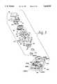
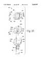
- FIG. 1is a perspective view of an electrofluidic module embodying the present invention
- FIG. 2is a perspective view of the electrofluidic module shown in FIG. 1, showing details of the bottom thereof;
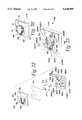
- FIG. 3is an exploded, perspective view of components of the electrofluidic module shown in FIG. 1 and further showing an underlying separate fixture, the combination of the module and the fixture comprising an electrofluidic assembly;
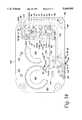
- FIG. 4is a plan view of a base layer of the electrofluidic module shown in FIG. 1;
- FIG. 5is a plan view of a first intermediate layer of the electrofluidic module shown in FIG. 1;
- FIG. 6is a plan view of a circuit layer with a superimposed device layer including a plurality of microvalves positioned on the circuit layer, which components are incorporated into the electrofluidic module shown in FIG. 1;
- FIG. 7is a plan view of a fluidic return cap for positioning over the device layer and the circuit layer;
- FIG. 8is a plan view of the electrofluidic module shown in FIG. 1;
- FIG. 9is a cross-section taken along lines 9--9 of FIG. 8, having the portions exploded to show details of a first fluid flow path through the module;
- FIG. 10is a cross-section taken along lines 10--10 of FIG. 8, having the portions exploded to show details of a second fluid flow path through the module;
- FIG. 11is an exploded perspective of the electrofluidic module shown in FIG. 1 shown in part schematically to illustrate two simultaneous flow paths through respective portions of the module;
- FIG. 12is a schematic diagram of the electrofluidic module shown in FIG. 1 illustrating the connections to a pair of electrical headers and a pair of fluid sources;
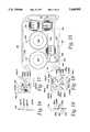
- FIG. 13is a rear elevational view of a piston body for a peritoneal dialysis system, the piston body being provided with passageways for delivering pneumatic signals for the control of a cassette forming a portion of a patient circuit;
- FIG. 14is another rear elevational view of the piston body of FIG. 13, also showing a base plate and, in broken lines, the positioning of three electrofluidic modules and their fluidic, electrical, and mechanical connections to the base plate and the piston body;
- FIG. 15is a further rear elevational view of the piston body and the base plate of FIG. 14, with three electrofluidic modules in place;
- FIG. 16is a side elevational view of a printed circuit board for use in an electrofluidic module mounting fixture
- FIG. 17is a plan view of the printed circuit shown in FIG. 16 showing details of a plurality of traces thereon;
- FIG. 18is a side elevational view of a base layer for supporting the printed circuit board shown in FIGS. 16 and 17;
- FIG. 19is a plan view of the base layer shown in FIG. 18 showing details of a plurality of fluidic passageways therein;
- FIG. 20is a perspective view of the electrofluidic module shown in FIG. 1 mounted upon the fixture;
- FIG. 21is a perspective view of the fixture shown in FIG. 20;
- FIG. 22is an exploded perspective view of the fixture shown in FIG. 21;
- FIG. 23is a plan view of a silicon micromachined valve
- FIG. 24is a section taken substantially along lines 24--24 of FIG. 23 showing details of the interior of the silicon micromachined valve.
- FIG. 25is an exploded perspective view of an alternative embodiment of the electrofluidic module having four microvalves therein.
- FIGS. 1 through 3a miniature electrofluidic module embodying the present invention is generally shown therein and identified by numeral 10. As shown in FIGS. 3 and 20, the electrofluidic module 10 may be mounted on a separate electrofluidic fixture 250, for fluidic and electronic communication between the module and the fixture.
- the miniature electrofluidic module 10may be constructed around a base unit or electrofluidic member 12, which may comprise three layers 24, 64, 80, as discussed in more detail below.
- the electrofluidic member 12supports a preferably substantially flat or planar device layer 13, including a plurality of micromachined devices 14.
- a plurality of electrical circuits 16is formed on the electrofluidic member 12, and the circuits are connected to the micromachined devices 14 to operate them in order to modulate fluid flow from a plurality of inlets or outlets 18 through the micromachined devices 14 and through a plurality of bidirectional ports 20, each of which may be selected to serve as an inlet or an outlet depending on the fluid distribution manifold paths, the state of the respective microactuators 14, and the positive or negative relative pressure at each port 20 with respect to the pressure at the associated inlet or outlet 18.
- a return fluid flow director or manifold cap 22completes a fluid flow path between the fluidic inlets or outlets 18 and the fluidic inlets/outlets 20.
- Manifold cap 22may be mounted above device layer 13 and be supported by the top electrofluidic member layer 80 and, thus, by the electrofluidic member 12.
- a pair of electrical connectors 23, which may each have five pins,provides an electrical coupling between the electrical circuits 16 and the environment in which the miniature electrofluidic module 10 operates.
- the module 10 and the fixture 250may be made from circuit board material such as FR-4 or from ceramic substrates such as aluminia or other ceramic materials, or from other suitable materials.
- the materialmay be selected with due consideration for its properties, such as convenience of fabrication (in the case of FR-4), inherent cleanliness and chemical resistance (in the case of aluminia and other common ceramic materials), and other properties such as insulating characteristics, light weight, machining capabilities, strength, cost-effectiveness, and such other factors as may be relevant for specific applications.
- the electrofluidic member 12comprises a substantially rectangular parallelepiped base layer 24 having a pair of rectangular side walls 26 and 28 and four chamfered corners 30, 32, 34 and 36.
- the inlets or outlets 18may comprise pressure inlet 58 and a subatmospheric exhaust or vacuum outlet 60.
- Pressure inlet passage 58may be provided with a blind pressure inlet bore 40, while vacuum outlet passage 60 may be provided with a blind vacuum outlet bore 42.
- These passagesserve to communicate pressurized or rarefied air, at a pressure above or below atmospheric pressure, but usually in the range of ⁇ 1.5 to 10 psig, preferably about ⁇ 5 psig.
- the electrofluidic module 10may be used to transmit pneumatic signals to actuate liquid valves, e.g., in medical devices such as automated peritoneal dialysis treatment systems.
- a pair of inlet or outlet O-rings 48 and 50are seated, respectively, within the bores 40 and 42.
- the inlet or outlet O-rings 48 and 50provide sealing between whatever pneumatic supply device is connected in fluid communication with the inlet 58 and the outlet 60.
- the inlet channel 58 and outlet channel 60respectively, couple either a source of pressurized air or a source of below-atmospheric pressure air through other layers to the micromachined valves 14.
- An intermediate manifold layer 64is positioned above the base layer 24 with passageways in fluid communication with inlets or outlets 18 and inlet/outlets 20. More specifically, the intermediate manifold layer 64 provides generalized routing between the microvalves 14 and the inlets or outlets 18 and inlet/outlets 20.
- the intermediate manifold 64is substantially flat and planar and has a plurality of slots formed therein. Included in the slots are an elongated pressure inlet slot 66, a substantially h-shaped vacuum outlet slot 68, and four inlet/outlet slots 70, 72, 74, and 76, see FIGS. 3, 5.
- a printed circuit board 80is positioned above the intermediate manifold layer 64 and has a plurality of electrical traces or conductive paths 16, which may include two sections 82 and 84 formed thereon by any conventional method of forming electrical traces on a printed circuit board, see FIGS. 6, 11.
- Base layer 24also is provided with four inlets or outlets 20, which will be identified with reference numerals 20a-d. As shown in FIGS. 2 and 3, inlets/outlets 20a-d are provided with blind bores 21a-d respectively, for receiving O-rings 51, which provide sealing for external connections or channels used to transmit fluids, e.g., for pneumatic actuating signals.
- each fluid flow path between the module passageways and the fixture passagewaysmay be substantially straight, smooth, unobstructed, and characterized by a relatively uniform cross-section or diameter.
- the layers 24, 64, 80 of electrofluidic member 12may be adhered to one another by a suitable adhesive compound or adhesive gaskets (not shown), to provide desirable fluid-tight, air-tight, and vacuum-tight characteristics.
- the micromachined devices 14may be surface-mounted onto printed circuit board 80.
- the return manifold cap 22may be mounted onto printed circuit board 80 by any suitable adhesive or fasteners, again, preferably air-tight and vacuum-tight around the cap/circuit board interface.
- the member 12 and, thus, the module 10,may be secured to a separate fixture 200, 250 (FIGS. 3, 14) through the use of any suitable fasteners, such as threaded bolts 54, or a snap-fit connection, or the like.
- the bolts 54may be inserted through bolt holes 81a-d in printed circuit board 80, bolt holes 65a-d in intermediate manifold layer 64, and bolt holes 25a-d in base layer 24, see FIGS. 4-6.
- the threads on bolts 54mate with threaded inserts 277 in fixture 250, FIG. 3, or in threaded bolt holes BH in fixture 200, FIG.
- Valve passageways 86-100communicate generally between the slots formed in the intermediate manifold layer 64 and the plurality of valves 14, FIG. 11.
- the valvespreferably are in a generally flat planar layer 13.
- the plurality of valves 14includes valves 110, 112, 114, 116, 118, 120, 122, and 124.
- the valvesform paired combinations 116 and 118, 114 and 120, 112 and 122, and 110 and 124, each of the valve pairs being associated via the respective inlet/outlet slots 70, 72, 74, and 76 with inlet/outlet ports 20a, 20b, 20c, and 20d.
- the cap or return manifold 22is positioned above the valves and has formed therein an elongated rectangular pressure manifold section 130 and a plurality of individualized vacuum manifold sections 132, 134, 136, and 138.
- the cap 22is made of clear polycarbonate or another suitable clear material to permit visual inspection of the microvalves and, in some cases, the fluids.
- FIG. 11examples are shown of a typical pressurized air flow path 128 and a typical subatmospheric air flow path 126. See also FIGS. 9 and 10.
- a vacuum sourceis coupled to air outlet or exhaust port 60 to draw a vacuum.
- the vacuumis communicated upstream from the vacuum source to the passageways and components as described hereafter.
- the vacuumis communicated to the vacuum slot 68 in intermediate manifold layer 64, and then to the overlying vacuum passageways 97-100 in circuit board 80.
- the vacuum passageways 97, 98, 99, 100communicate vacuum to the overlying vacuum-side valves 116, 114, 112, 110, respectively, which places a reduced pressure on the undersides of those valves (FIG. 11).
- typical vacuum-side valve 110is caused to be opened by providing a suitable electrical signal on the traces 84, vacuum is communicated from valve 110 to vacuum manifold chamber 138, from thence to aperture 96, to the inlet/outlet slot 76 comprising a passageway, and ultimately to the inlet/outlet opening 20d.
- the air flowwill be from the relatively higher pressure inlet/outlet port 20d, proceeding along the typical vacuum side air path 126 to vacuum exhaust port 60, where air at subatmospheric pressure will be exhausted to the vacuum source.
- FIG. 11 and also to FIG. 9a typical vacuum-side air flow path 126 is shown, with the arrowheads designating the direction of air flow.
- typical vacuum-side valve 110Upon opening typical vacuum-side valve 110, air is drawn into the inlet/outlet passageway 20d, upwardly through inlet/outlet slot 76, upwardly through aperture 96, upwardly through vacuum manifold section 138, and then downwardly through valve 110, aperture 100, L-shaped vacuum outlet slot 68, and ultimately outwardly through vacuum exhaust passageway 60, FIGS. 9 and 11.
- the manner in which the module 10 is plumbedcauses the vacuum valves 110-116 to have lower pressure presented at the undersides of the valves rather than on top, thereby biasing valves 110-116 closed.
- the valves 110, 112, 114, 116overlie vacuum apertures 100, 99, 98, 97, respectively, and the apertures communicate with vacuum slot 68, upon which a vacuum is drawn through exhaust port 60.
- the pressure maintained in manifold section 130biases valves 118-124 closed.
- a typical pressurized air stream 128may be supplied through the pressure inlet 58, upwardly through the pressure inlet slot 66, and thence upwardly through pressure distribution apertures 86, 87, and 88, into the pressure header 130, and thence downwardly to the tops of pressure-side valves 118-124. If electrical energy is supplied to the valve 118 through the leads 82 (FIGS. 6, 11), the valve 118 opens, connecting a positive pressure flow path downwardly through aperture 89 to the inlet/outlet slot 70, providing an outlet pressure stream 128 through outlet 20a (FIGS. 10, 11).
- the electrofluidic module 10 of the inventionmay be used to mix two or more streams, such as two gases or two liquids of different composition, or to add or subtract actuating signals such as air pressures.
- the mixing or additionmay be accomplished by opening both of two paired microvalves, e.g., 110 and 124.
- the effect of opening both microvalves 110, 124would be to add the positive gauge pressure at inlet 58 to the negative gauge pressure at exhaust 60, the sum being approximately the expected pressure at the inlet/outlet 20d associated with the paired valves.
- the module 10may be used to provide fluidic logic capabilities.
- Other uses of the invention for fluidic logic purposeswill be apparent to those skilled in the art.
- FIG. 12a schematic drawing of the electrical circuitry and the fluid flow paths within module 10 is provided. It may be observed that the eight two-way valves 14 of module 10 are configured to perform the equivalent function of four three-way selector valves. For each inlet/outlet 20, a pair of valves associated therewith permits either of two fluid streams (e.g., pressurized air or rarefied air) to pass through the inlet/outlet 20.
- two fluid streamse.g., pressurized air or rarefied air
- the base layer 24may be provided with any desired number and configuration of inlets or outlets.
- the intermediate manifold layer 64may be provided with any desired number and configuration of channels or slots.
- the circuit board layer 80, device layer 13, and return manifold cap 22provide similar flexibility in their design and operation.
- electrofluidic interfaces or connections provided by the inventioncan be standardized to any number of predetermined standards.
- One of these standard interfacesis that disclosed for the preferred embodiment 10.
- An analogycan be drawn to standard electronic components, such as transistors, particularly those packaged in a standard DIP (dual-in-line) package configuration.
- two additional blind bores or blanks 44are shown. They are used to symmetrically balance the loading on the module when it is secured an external pneumatic device. Depending on the specific flow configuration and the specific standard interface desired, these bores 44 could be provided with passageways therethrough to the opposite side of base layer 24 in order to provide fluid communication between an external pneumatic device and the internal components such as manifold 64 within module 10. Similarly, the invention permits the use of almost any number of inlets and outlets 18 and 20 and a wide variety of internal flow paths, as determined by the configuration of each of the various layers 13, 22, 24, 64, 80 within module 10.
- any desired additional passageways or variations in flow configurationwill be provided at the time of manufacture, construction, or assembly of the module 10, in accordance with a predetermined design, in order to benefit from economies of scale in manufacturing large quantities of the selected standard module.
- the miniature electrofluidic module 10may be used in a dialysis system or an electrofluidic dialysate handling system including a piston body 200, as may best be seen in FIGS. 13-15.
- the piston body 200preferably is made of DELRIN (an acetyl compound), or another suitable material to withstand repeated stresses.
- DELRINan acetyl compound
- the dialysate handling systemis disclosed in more detail in U.S. Pat. No. 5,324,422 to Colleran, et al. and U.S. Pat. No. 5,350,357 to Kamen, et al., both of which patents are incorporated herein by reference as if fully reproduced herein.
- a plurality of miniaturized electrofluidic modules 10, respectively numbered 190, 192, 194,are positioned on a base plate 196, forming a sealing connection over fluidic conducting lines or grooves 210g, 212g, 214g, 216g, 218g, 220g, 224g, 226g, 228g, 230g, 232, and 234, all of which grooves are formed in the piston body 200.
- the combination of the base plate or fixture 196 and electrofluidic modules 190, 192, and 194is an electrofluidic assembly 198.
- FIG. 13shows the piston body 200 after said grooves have been machined.
- FIG. 14shows base plate 196 mounted on the rear surface 201 of piston body 200, covering said grooves (shown in broken lines). Threaded bolt holes BH are tapped into the base plate and into the piston body 200, for receiving threaded bolts 54 to attach modules 190, 192, 194. The positions for said modules and their bottom surface bores 21a-d and electrical connectors 23 are shown in broken lines. Fluid passageways, e.g., for module 194, the passageways identified with reference numerals 230a, 228b, 224c, 226d, HP, and LP, are drilled through base plate 196, in order to permit fluids to communicate between the piston body 200 and each module. Similar passageways are provided for modules 190, 192. Finally, the modules are shown mounted on base plate 196 and piston body 200, FIG. 15.
- the piston body 200is used to pneumatically actuate a multi-component cassette (not shown) including two diaphragm pumps and ten liquid valves.
- the pump actuators 202, 204receive pneumatic actuating signals through ports 206, 208, respectively.
- the ten liquid valves (not shown)are actuated by pneumatic signals transmitted through ten ports 210p, 212p, 214p, 216p, 218p, 220p, 224p, 226p, 228p, 230p. These ports extend from the rear of the piston body 200 (FIG. 13) to the piston front (not shown), where they deliver pneumatic signals to cause respective portions of a membrane in the cassette to seat or unseat and, thus, to actuate the respective liquid valves.
- each of the ten portsrequired a separate length of flexible plastic tubing extending from a remote housing where positive or negative pressure signals were selectively generated and transmitted through the separate tubes to the respective ports.
- a positive pressure channel or groove 232 and a negative or subatmospheric pressure groove 234are machined into the rear surface of the piston body 200 (FIG. 13). Connections or barbs 236 and 238 are provided for connection to external pressure and vacuum supplies, respectively.
- the piston body 200also is provided with standard interface connections in a predetermined geometry to mate with a selected standard electrofluidic module 10.
- mating receptacles a, b, c, dare machined into the piston body rear surface 201 for receiving connection to module inlets/outlets 20a, 20b, 20c, 20d, respectively, for as many such connections as may be desired.
- ports 230p, 228p, 224p, and 226pare connected via grooves 230g, 228g, 224g, and 226g to standard-positioned receptacles 230a, 228b, 224c, and 226d, respectively.
- a relatively high pressure connection HP and a relatively low pressure connection LPare positioned for mating to standard module inlets or outlets 58, 60, respectively.
- ports 220p, 218p, 214p, and 216pare connected via grooves 220g, 218g, 214g, and 216g to standard-positioned receptacles 220a, 218b, 214c, 216d, respectively.
- the ports 210p and 212pare connected via grooves 210g and 212g to receptacles 210d and 212 b.
- Base plate 196also is provided with a master electrical pin connector 240 for receiving electrical signals via a ribbon cable (not shown) for activating the microdevices 14.
- Circuit traces(not shown) are provided on the base plate 196 for connection to the individual module electrical pin connectors 23 for actuation of the total of twenty (20) valves 14 used in the three modules 190, 192, 194.
- the supply voltagemay be about 3.5-5.0 VDC. This supply is provided via the ribbon cable and the circuit traces.
- the circuitry for base plate 196may be similar to that shown for Fixture 250, see FIGS. 3 and 21, but with additional traces to accommodate the three modules 190, 192, 194.
- valveswill be controlled by a bank of transistors or latched drivers (not shown), thereby limiting the number of lines needed for connection to an external controller.
- a bank of transistors or latched drivers(not shown), thereby limiting the number of lines needed for connection to an external controller.
- BiMOS II 32-bit serial input latched drivers in a 44 lead plastic chip carrier, Model No. UCN-5833EP, available from Allegro Microsystemsmay be used, as will be understood by those of ordinary skill in the art.
- each module 10numbered as 190, 192, 194 the bottom of the module is provided with four inlet/outlet blind bores 21a-d which communicate with the internal parts of the module via inlet/outlets 20a-d, respectively (FIGS. 1-3).
- Each modulealso is provided with a blind pressure inlet bore 40 and blind vacuum outlet bore 42, which communicate to the internal parts of the module via pressure inlet channel 58 and vacuum outlet channel 60.
- Each module 190, 192, 194is mounted with bores 21a-d, 40, 42 in registration with the underlying and corresponding receptacles in the piston body.
- bore 21dregisters and communicates with receptacle 210d
- bore 21bregisters and communicates with receptacle 212b.
- blind bores 21a and 21care not used.
- Blind pressure inlet bore 40mates with pressure connection HP to communicate between the module 190 and pressure supply groove 232.
- Blind vacuum outlet bore 42mates with vacuum connection LP to communicate between module 190 and low pressure groove 234.
- module bores 21a, 21b, 21c, 21d, 40, and 42mate with piston body receptacles 220a, 218b, 214c, 216d, HP, and LP, respectively.
- module bores 21a, 21b, 21c, 21d, 40, and 42mate with piston body receptacles 230a, 228b, 224c, 226d, HP, and LP, respectively.
- base plate 196is provided with holes or apertures (not shown) in registration with the piston body receptacles to permit communication with the module bores.
- FIGS. 20-21Another example of the use of the miniaturized electrofluidic module 10 involves mounting upon a fixture 250, as may best be seen in FIGS. 20-21, comprising an electrical circuit board layer 252 having a pair of connectors 254 and 256 connected via a plurality of traces 260 to a set of bonding pads 262.
- the electrical connectors 254 and 256connect with the module electrical connectors 23.
- a thin intermediate sheet 270is positioned with a pair of positioning pins 274 and 276 with respect to a base layer 278 having a plurality of passages or grooves 280g, 282g, 284g, 286g, 288g, 290g, formed thereon.
- FIG. 19Another example of the use of the miniaturized electrofluidic module 10 involves mounting upon a fixture 250, as may best be seen in FIGS. 20-21, comprising an electrical circuit board layer 252 having a pair of connectors 254 and 256 connected via a plurality of traces 260 to a set of bond
- the bores in base layer 278may be adapted for making connections to external fluidic tubes or the like.
- bores 288p and 290pcommunicate with external connections through the top of base layer 278, while the other bores, such as bore 280B, communicate with external connections through the bottom of base layer 278.
- the mating connectionsmay be made more durable or robust through the use of grooved inserts or barbs made from brass or other suitable materials.
- the fixture 250may be provided with four bolt holes 278BH in base layer 278, matching bolt holes in gasket layer 270, and similarly aligned bolt holes 252BH in circuit board 252. Threaded inserts 277 may be secured by press (interference) fit into the bolt holes to provide a secure and robust but releasable connection for threaded bolts 54, used to register and releasably mount module 10 onto fixture 250.
- an electrofluidic assembly 198may be comprised of one or more electrofluidic modules 10 mounted on a suitable fluidic fixture 250 or a base plate 196 on a fluidic piston body 200.
- the electrofluidic assembly 198comprises three electrofluidic modules 10 mounted on a base plate 196 attached to fluidic piston body 200.
- each moduleincludes an electrofluidic member having a fluidic manifold and an electrical circuit.
- a simplified electrofluidic membermay comprise an electrical circuit board having fluidic passageways therein, e.g., the circuit board 80 or the circuit board 252.
- the simplified electrofluidic membermay be configured for mounting directly and perhaps permanently onto an underlying fluidic fixture, e.g., fixture 250 or piston body 200.
- Devicessuch as microvalves 14 may be mounted directly and permanently onto the electrofluidic member, and a return manifold may be placed over such devices and also be mounted directly onto the electrofluidic member.
- each componentis mounted directly and perhaps permanently over the underlying components, preventing quick and easy replacement of defective components or groups.
- microvalvescan be subject to failure and the need for replacement.
- the assemblymay comprise fewer layers, with possibly improved reliability due to fewer components, but the advantages of easy module installation and replacement may be lacking, due to the lack of standard mating fluidic, electrical, and mechanical interfaces provided by the preferred modular assembly.
- each of the microactuators 14comprises a microvalve having a central boss 300, a pair of power leads 302 and 304 connected to a bridge region 306 near the boss 300 to effect movement of the boss 300 toward and away from a valve seat 309 to open and close the valve.
- the bosswhen the valve 14 is closed, has a higher pressure applied to an upper surface 312 than is present at the passageway 314 directly connected to the valve seat, contributing to a bias-closed design for the preferably normally closed valve.
- the microvalvemay have very small dimensions, e.g., approximately 0.16 ⁇ 0.16 ⁇ 0.024 inch.
- the valvefeatures proportional response, low power requirements, low cost, fast response, miniature size, a wide range of operating pressures up to about 25 to 30 psig.
- Each valvemay be mounted on a printed circuit board 80 (FIG. 3) or the like.
- Typical applications for the inventive module and assemblyinclude I/P converters, pneumatic controls, respirators/ventilators, medical instrumentation, pressure regulators, flow controls, and analytical instruments.
- the microvalves 14consist of a centrally bossed silicon diaphragm mated to an etched silicon valve body. An aluminum film is deposited on the diaphragm to form a bimetallic actuator. By varying the electrical power dissipated in resistors implanted in the diaphragm, and thus the temperature of the actuator, the thermal expansion difference between silicon and metal results in the controlled displacement of the central boss away from the valve seat.
- Filtersare recommended to keep particles from entering the module or valve chip, and a filtered, clean gas supply source is recommended.
- Performance specifications for the microvalve 14, at 25° C. unless otherwise,may be as follows: The typical power requirement for each microvalve is 300-500 mW, the response time is about 100-200 msec (at 10 to 90% flow), the internal volume of the valve is about 0.12 cc, the operating voltage is about 3.5-5.0 VDC, the operating current is about 85-100 mA, the actuator resistance is about 40 ohm, the burst pressure limit is about 50 psi, and the back pressure limit is about 25 psi. Operating temperature range is +20° C. to +70° C., weight is about 0.3 gram, and recommended supply filtration is 25 microns. The above specifications are approximate, and are specific to the microvalve used in IC Sensors Model 4425. Other microactuators may be used in the module 10 without departing from the scope of the invention. Typical flow rates are 100-300 sccm for each open microvalve, but much greater flow rates are possible.
- the response time of the liquid valveis less than about 100 msec, measured from the time an actuating electrical signal is sent to a microactuator 14 in module 10.
- the size of module 10may be about 1.0 ⁇ 1.0 ⁇ 7/16 inch.
- Each passageway within the modulemay have a diameter of about 1/16 inch, the bolt holes 25, 65, 81 may be slightly larger in diameter than the passageways, and the bores 40, 42, 44 may be about 3/32 inch in diameter.
- the ports 20a-dare spaced about 6 mm apart, center to center, in a straight line. Inlets or outlets 18 are spaced about 8 mm from ports 20a and 20d, at right angles to (and both on the same side of) said straight line.
- the pinsmay be spaced 1 mm apart, center to center, in a straight line.
- the line formed by the pins of one connector 23may be parallel to and spaced about 21 mm from the line formed by the pins of the other connector 23.
- Each port 18, 20a-dmay be about 1/16" in diameter.
- the electrical traces on each of the circuit boards disclosed hereinmay be made of any suitable conductive material, but preferably are made of gold because of its excellent conductivity and non-corrosive properties.
- Four-valve electrofluidic module 310is shown in FIG. 25. It includes a base layer 324, an intermediate manifold layer 364, an electrical layer 380, a device layer of microvalves 410, 412, 418, 420, and a return layer 322.
- the base 324may receive an inlet of a pressurized gas stream 426 through an inlet 358, which is passed to a pressure slot 366.
- Pressure slot 366communicates via slot 392 into a pressure manifolding section 430 of the return layer 322.
- Manifold section 430communicates pressure to the tops of two pressure-side microvalves 410, 412. Electrical signals can be transmitted via electrical traces 316 to open either or both of valves 410, 412 to transmit pressure downwardly and ultimately out through inlet/outlets 320b, 320a, respectively. For example, if valve 410 is opened, pressure will be transmitted to inlet/outlet slot end 372a, and then rearwardly to slot end 372b, downwardly to inlet or outlet passageway 320b, and out through the base layer 324, via an O-ring seal 350 for connection to a separate fixture.
- Base 324also is provided with a vacuum or subatmospheric exhaust passageway 360 for exhausting low pressure gas stream 428 to an external low-pressure system (not shown).
- Low pressure airmay be drawn into either or both of the inlet/outlets 320a, 320b, by opening valves 418, 420, respectively.
- valve 418is opened, low pressure air will be drawn into passageway 320a, upwardly to slot end 370b, upwardly through aperture 388 into vacuum manifold section 432, and downwardly through valve 418, into end 368b of h-shaped slot 368, laterally to end 368a, and down and out through vacuum exhaust outlet 360.
- the system 310also includes a pin connector 323 for coupling to electrical traces 316 on the electrical layer 380. Those traces are connected to the microvalves 410, 412, 418, 420 to control whether they are open or closed.
- a plurality of "O" rings 350are mounted in bores in the underside of base 324 to form fluid-tight connections between the passageways 320a, 320b, 358, 360, and mating external connections.
- the operation of the four-valve embodiment 310is substantially similar to that of the eight-valve electrofluidic module 10.
- valve module 310could be substituted for an eight valve module 10 in applications requiring only two fluidic inputs and two fluidic input/output ports, for example to replace eight valve module 190 (of which only four valves are used) as shown in FIGS. 14, 15, provided that the fixture 196, 200 is configured with fluidic, electrical, and mechanical interfaces to mate with the four valve module 310.
Landscapes
- Engineering & Computer Science (AREA)
- General Engineering & Computer Science (AREA)
- Health & Medical Sciences (AREA)
- Mechanical Engineering (AREA)
- Dispersion Chemistry (AREA)
- Chemical & Material Sciences (AREA)
- Heart & Thoracic Surgery (AREA)
- Public Health (AREA)
- Urology & Nephrology (AREA)
- Life Sciences & Earth Sciences (AREA)
- Animal Behavior & Ethology (AREA)
- General Health & Medical Sciences (AREA)
- Biomedical Technology (AREA)
- Veterinary Medicine (AREA)
- Anesthesiology (AREA)
- Vascular Medicine (AREA)
- Hematology (AREA)
- Emergency Medicine (AREA)
- Computer Hardware Design (AREA)
- Microelectronics & Electronic Packaging (AREA)
- Theoretical Computer Science (AREA)
- Physics & Mathematics (AREA)
- Fluid Mechanics (AREA)
- Micromachines (AREA)
- Fluid-Pressure Circuits (AREA)
- External Artificial Organs (AREA)
Abstract
Description
Claims (37)
Priority Applications (6)
| Application Number | Priority Date | Filing Date | Title |
|---|---|---|---|
| US08/404,301US5640995A (en) | 1995-03-14 | 1995-03-14 | Electrofluidic standard module and custom circuit board assembly |
| JP52757596AJP4340926B2 (en) | 1995-03-14 | 1996-01-26 | Electrofluidic standard module and custom circuit board assembly |
| PCT/US1996/001246WO1996028664A1 (en) | 1995-03-14 | 1996-01-26 | Electrofluidic standard module and custom circuit board assembly |
| CA002214510ACA2214510C (en) | 1995-03-14 | 1996-01-26 | Electrofluidic standard module and custom circuit board assembly |
| EP96907859AEP0821766B1 (en) | 1995-03-14 | 1996-01-26 | Electrofluidic module |
| DE69627844TDE69627844T2 (en) | 1995-03-14 | 1996-01-26 | ELECTROFLUIDIC MODULE |
Applications Claiming Priority (1)
| Application Number | Priority Date | Filing Date | Title |
|---|---|---|---|
| US08/404,301US5640995A (en) | 1995-03-14 | 1995-03-14 | Electrofluidic standard module and custom circuit board assembly |
Publications (1)
| Publication Number | Publication Date |
|---|---|
| US5640995Atrue US5640995A (en) | 1997-06-24 |
Family
ID=23599061
Family Applications (1)
| Application Number | Title | Priority Date | Filing Date |
|---|---|---|---|
| US08/404,301Expired - LifetimeUS5640995A (en) | 1995-03-14 | 1995-03-14 | Electrofluidic standard module and custom circuit board assembly |
Country Status (6)
| Country | Link |
|---|---|
| US (1) | US5640995A (en) |
| EP (1) | EP0821766B1 (en) |
| JP (1) | JP4340926B2 (en) |
| CA (1) | CA2214510C (en) |
| DE (1) | DE69627844T2 (en) |
| WO (1) | WO1996028664A1 (en) |
Cited By (140)
| Publication number | Priority date | Publication date | Assignee | Title |
|---|---|---|---|---|
| WO1998005871A1 (en)* | 1996-08-06 | 1998-02-12 | Gaswärme-Institut e.V. | Valve arrangement |
| WO1999009388A3 (en)* | 1997-08-18 | 1999-05-06 | Metasensors Inc | Method and apparatus for real time gas analysis and medical fluids monitoring |
| WO1999043432A1 (en)* | 1998-02-24 | 1999-09-02 | Caliper Technologies Corporation | Microfluidic devices and systems incorporating cover layers |
| US5964239A (en)* | 1996-05-23 | 1999-10-12 | Hewlett-Packard Company | Housing assembly for micromachined fluid handling structure |
| EP0955473A1 (en) | 1998-05-08 | 1999-11-10 | Festo AG & Co | Valve array |
| US6042079A (en)* | 1996-07-18 | 2000-03-28 | Mikroskopie Und Systeme Gmbh | Device for vibration isolation |
| US6080957A (en)* | 1996-09-17 | 2000-06-27 | Deutsche Forschungsanstalt Fuer Luft-Und Raumfahrt E.V. | Micromechanical tool |
| US6102068A (en)* | 1997-09-23 | 2000-08-15 | Hewlett-Packard Company | Selector valve assembly |
| DE19909069A1 (en)* | 1999-03-02 | 2000-09-21 | Hahn Schickard Ges | Microvalue assembly with micromechanically mfd. microvalve chip for 2/2 and 3/2 fluid flow control |
| US6137169A (en)* | 1997-07-10 | 2000-10-24 | Pace; Adolfo | Heat reduction system for transistor assemblies |
| US6152175A (en)* | 1997-06-06 | 2000-11-28 | Ckd Corporation | Process gas supply unit |
| DE19921660A1 (en)* | 1999-05-11 | 2000-11-30 | Festo Ag & Co | Micro valve assembly has micro valve fixed on housing by valve support which defines fluid duct system for valve and uncouples micro valve from mechanical and thermal influences of housing |
| DE19921659A1 (en)* | 1999-05-11 | 2000-12-07 | Festo Ag & Co | Microvalve assembly, e.g. for pneumatic system, has housing with molded interconnect device structure for electrically connecting electronic drive components and microvalves |
| US6230501B1 (en) | 1994-04-14 | 2001-05-15 | Promxd Technology, Inc. | Ergonomic systems and methods providing intelligent adaptive surfaces and temperature control |
| US6286360B1 (en) | 1999-02-25 | 2001-09-11 | Metasensors, Inc. | Methods and apparatus for real time fluid analysis |
| WO2001086155A1 (en) | 2000-05-12 | 2001-11-15 | Central Research Laboratories Limited | An adaptor for receiving a fluidic device |
| DE20115733U1 (en) | 2001-09-25 | 2001-12-20 | FESTO AG & Co., 73734 Esslingen | Valve device |
| WO2002040901A1 (en)* | 2000-04-13 | 2002-05-23 | California Institute Of Technology | Micromachined rubber o-ring microfluidic couplers |
| US20020119078A1 (en)* | 2000-05-24 | 2002-08-29 | Petr Jansa | Device and method for addressing a microfluidic cartridge |
| US6443179B1 (en) | 2001-02-21 | 2002-09-03 | Sandia Corporation | Packaging of electro-microfluidic devices |
| US20020124896A1 (en)* | 2000-10-12 | 2002-09-12 | Nanostream, Inc. | Modular microfluidic systems |
| US20020125139A1 (en)* | 2000-08-03 | 2002-09-12 | Caliper Technologies Corp. | Methods and devices for high throughput fluid delivery |
| US6488315B1 (en)* | 1997-10-22 | 2002-12-03 | Merck Patent Gmbh | Coupling for microcomponents |
| US20020185431A1 (en)* | 2001-06-07 | 2002-12-12 | Nanostream, Inc. | Microfluidic filter |
| US6548895B1 (en) | 2001-02-21 | 2003-04-15 | Sandia Corporation | Packaging of electro-microfluidic devices |
| US6561208B1 (en) | 2000-04-14 | 2003-05-13 | Nanostream, Inc. | Fluidic impedances in microfluidic system |
| US6585732B2 (en) | 1995-02-22 | 2003-07-01 | Medtronic, Inc. | Fluid-assisted electrosurgical device |
| US20030125618A1 (en)* | 2001-10-04 | 2003-07-03 | Scimed Life Systems, Inc. | Angiographic fluid control system |
| US20030133358A1 (en)* | 2002-01-11 | 2003-07-17 | Nanostream, Inc. | Multi-stream microfluidic aperture mixers |
| US6626468B2 (en)* | 2000-07-27 | 2003-09-30 | Toshiba Tec Kabushiki Kaisha | Pipe joint, its manufacturing method, and fluid device using the same |
| US6629949B1 (en) | 2000-05-08 | 2003-10-07 | Sterling Medivations, Inc. | Micro infusion drug delivery device |
| US6632400B1 (en)* | 2000-06-22 | 2003-10-14 | Agilent Technologies, Inc. | Integrated microfluidic and electronic components |
| US20030198130A1 (en)* | 2000-08-07 | 2003-10-23 | Nanostream, Inc. | Fluidic mixer in microfluidic system |
| US6659982B2 (en) | 2000-05-08 | 2003-12-09 | Sterling Medivations, Inc. | Micro infusion drug delivery device |
| US20040042340A1 (en)* | 2002-08-28 | 2004-03-04 | Shimadzu Corporation | Mixer for liquid chromatograph |
| US20040048132A1 (en)* | 2001-09-26 | 2004-03-11 | Yuichi Takai | Fuel cell and electronic device using fuel cell |
| US20040089357A1 (en)* | 2002-06-21 | 2004-05-13 | Christopher Dube | Integrated electrofluidic system and method |
| US20040112593A1 (en)* | 2002-12-17 | 2004-06-17 | Mcgregor Ronald W. | Hydraulic circuit construction in downhole tools |
| US20040141884A1 (en)* | 1999-08-19 | 2004-07-22 | Caliper Technologies Corp. | Indicator components for microfluidic systems |
| US20040228770A1 (en)* | 1998-02-24 | 2004-11-18 | Caliper Life Sciences, Inc. | Microfluidic devices and systems incorporating cover layers |
| US20040228771A1 (en)* | 2003-05-15 | 2004-11-18 | Kionix, Inc. | Reconfigurable modular microfluidic system and method of fabrication |
| US20050035174A1 (en)* | 2001-02-02 | 2005-02-17 | Mitsubishi Heavy Industries, Ltd. | Integrated piping plate, machining method for same, machining apparatus for same, and machining equipment for same |
| US20050068726A1 (en)* | 2003-09-25 | 2005-03-31 | Harris Corporation | Electro-fluidic device and interconnect and related methods |
| NL1024486C2 (en)* | 2003-10-08 | 2005-04-11 | Lionix B V | Coupling a component of a module to a component of a motherboard comprises using rigid coupling elements with passages for the exchange of signals between the two components |
| US6890093B2 (en) | 2000-08-07 | 2005-05-10 | Nanostream, Inc. | Multi-stream microfludic mixers |
| US6897557B2 (en) | 2001-06-19 | 2005-05-24 | The Regents Of The University Of California | Integrated electrical connector |
| US6918893B2 (en) | 2001-10-04 | 2005-07-19 | Scimed Life Systems, Inc. | Multiple port fluid control valves |
| EP1275853A3 (en)* | 2001-07-11 | 2005-10-19 | Xerox Corporation | Muscle-emulating PC board actuator |
| US20050277887A1 (en)* | 2000-05-08 | 2005-12-15 | Joel Douglas | Micro infusion drug delivery device |
| US7059351B1 (en)* | 2005-12-05 | 2006-06-13 | National Taiwan University | Surface-tension-guided liquid transportation device |
| DE102004062923A1 (en)* | 2004-12-28 | 2006-07-06 | Hirschmann Laborgeräte GmbH & Co. KG | Device for conveying fluids, method for producing the same and pipette with such a device |
| US20060195064A1 (en)* | 2005-02-28 | 2006-08-31 | Fresenius Medical Care Holdings, Inc. | Portable apparatus for peritoneal dialysis therapy |
| US20060272718A1 (en)* | 2005-06-03 | 2006-12-07 | Honeywell International Inc. | Microvalve package assembly |
| US7172572B2 (en) | 2001-10-04 | 2007-02-06 | Boston Scientific Scimed, Inc. | Manifold system for a medical device |
| US7219449B1 (en) | 1999-05-03 | 2007-05-22 | Promdx Technology, Inc. | Adaptively controlled footwear |
| US7264617B2 (en)* | 2000-02-29 | 2007-09-04 | Alex Freeman | Integrally manufactured micro-electrofluidic cables |
| US20080044312A1 (en)* | 2006-08-15 | 2008-02-21 | The Government Of The Us, As Represented By The Secretary Of The Navy | Method and apparatus for attaching a fluid cell to a planar substrate |
| US20080058192A1 (en)* | 2006-09-05 | 2008-03-06 | Samsung Electronics Co., Ltd. | Centrifugal force based microfluidic device having thermal activation unit, microfluidic system including the same and method of operating the microfluidic system |
| US20080097283A1 (en)* | 2006-08-31 | 2008-04-24 | Plahey Kulwinder S | Data communication system for peritoneal dialysis machine |
| US20080125693A1 (en)* | 2006-08-31 | 2008-05-29 | Gavin David A | Peritoneal dialysis systems and related methods |
| US20080250633A1 (en)* | 2006-03-30 | 2008-10-16 | C2V B.V. | Method for Building a Device Having Fluidic and Electrical Functions |
| US20080296226A1 (en)* | 2007-05-29 | 2008-12-04 | Fresenius Medical Care Holdings, Inc. | Solutions, Dialysates, and Related Methods |
| US20090012461A1 (en)* | 2007-07-05 | 2009-01-08 | Baxter International Inc. | Dialysis system having disposable cassette and heated cassette interface |
| US20090012457A1 (en)* | 2007-07-05 | 2009-01-08 | Baxter International Inc. | Dialysis system having disposable cassette and interface therefore |
| US20090040864A1 (en)* | 2007-08-07 | 2009-02-12 | International Business Machines Corporation | Microfluid mixer, methods of use and methods of manufacture thereof |
| US20090076433A1 (en)* | 2007-09-19 | 2009-03-19 | Folden Thomas I | Automatic prime of an extracorporeal blood circuit |
| US20090215194A1 (en)* | 2006-06-23 | 2009-08-27 | Stmicroelectronics, S.R.L | Assembly of a microfluidic device for analysis of biological material |
| US7935074B2 (en) | 2005-02-28 | 2011-05-03 | Fresenius Medical Care Holdings, Inc. | Cassette system for peritoneal dialysis machine |
| US20110228489A1 (en)* | 2010-03-17 | 2011-09-22 | Delta Design Inc. | Devices with pneumatic, hydraulic and electrical components |
| US20120025116A1 (en)* | 2010-07-30 | 2012-02-02 | Smc Corporation | Multiple manifold valve |
| US8142653B2 (en) | 2002-06-04 | 2012-03-27 | Fresenius Medical Care Deutschland Gmbh | Medical fluid cassettes and related systems |
| US20120085425A1 (en)* | 2007-10-24 | 2012-04-12 | Baxter Healthcare S.A. | Personal hemodialysis system |
| US8192401B2 (en) | 2009-03-20 | 2012-06-05 | Fresenius Medical Care Holdings, Inc. | Medical fluid pump systems and related components and methods |
| CN102734278A (en)* | 2012-07-19 | 2012-10-17 | 北京理工大学 | Hierarchical design method for hydraulic control module of electrohydraulic control system |
| US20130269801A1 (en)* | 2007-10-30 | 2013-10-17 | Baxter Healthcare S.A. | Pressure manifold system for dialysis |
| US20130280102A1 (en)* | 2012-04-20 | 2013-10-24 | Tom M. Simmons | Fluid pumps, methods of manufacturing fluid pumps, and methods of pumping fluid |
| US8692167B2 (en) | 2010-12-09 | 2014-04-08 | Fresenius Medical Care Deutschland Gmbh | Medical device heaters and methods |
| US8720913B2 (en) | 2009-08-11 | 2014-05-13 | Fresenius Medical Care Holdings, Inc. | Portable peritoneal dialysis carts and related systems |
| US20140208827A1 (en)* | 2013-01-25 | 2014-07-31 | Rosemount Analytical Inc. | Hermetic manifold for analytical instruments |
| EP2489884A3 (en)* | 2011-02-21 | 2014-10-08 | Ion Science Limited | Pneumatic Manifold |
| AU2013209331B2 (en)* | 2007-10-24 | 2014-11-20 | Baxter Healthcare Sa | Hemodialysis systems and methods for same |
| US8932032B2 (en) | 2005-07-13 | 2015-01-13 | Fresenius Medical Care Holdings, Inc. | Diaphragm pump and pumping systems |
| US8973613B2 (en) | 2011-04-27 | 2015-03-10 | Google Inc. | Electrorheological valve |
| US9011114B2 (en) | 2011-03-09 | 2015-04-21 | Fresenius Medical Care Holdings, Inc. | Medical fluid delivery sets and related systems and methods |
| US20150144818A1 (en)* | 2013-11-26 | 2015-05-28 | Eugene M. Cummings | Test and monitoring system for a sump pump installation having a self-protecting valve assembly for admitting water to the sump container |
| US9180240B2 (en) | 2011-04-21 | 2015-11-10 | Fresenius Medical Care Holdings, Inc. | Medical fluid pumping systems and related devices and methods |
| US9186449B2 (en) | 2011-11-01 | 2015-11-17 | Fresenius Medical Care Holdings, Inc. | Dialysis machine support assemblies and related systems and methods |
| US9404501B2 (en) | 2013-11-26 | 2016-08-02 | Beacon Technical Systems, Llc | Sump pump test and monitoring system |
| US9421314B2 (en) | 2009-07-15 | 2016-08-23 | Fresenius Medical Care Holdings, Inc. | Medical fluid cassettes and related systems and methods |
| US9433718B2 (en) | 2013-03-15 | 2016-09-06 | Fresenius Medical Care Holdings, Inc. | Medical fluid system including radio frequency (RF) device within a magnetic assembly, and fluid cartridge body with one of multiple passageways disposed within the RF device, and specially configured cartridge gap accepting a portion of said RF device |
| US9441753B2 (en) | 2013-04-30 | 2016-09-13 | Boston Dynamics | Printed circuit board electrorheological fluid valve |
| US9500188B2 (en) | 2012-06-11 | 2016-11-22 | Fresenius Medical Care Holdings, Inc. | Medical fluid cassettes and related systems and methods |
| US9525309B2 (en) | 2013-11-26 | 2016-12-20 | Beacon Technical Systems, Llc | Battery-powered backup power system for a sump pump installation |
| US9528873B2 (en) | 2013-11-26 | 2016-12-27 | Beacon Technical Systems, Llc | Test and monitoring system for a sump pump installation having a self-monitoring liquid level sensing module |
| US9528512B2 (en) | 2013-11-26 | 2016-12-27 | Beacon Technical Systems, Llc | Test and monitoring system for a battery-powered DC pump installation |
| US9528523B2 (en) | 2013-11-26 | 2016-12-27 | Beacon Technical Systems, Llc | Test and monitoring system for a sump pump installation having a variable test cycle time out |
| US9528522B2 (en) | 2013-11-26 | 2016-12-27 | Beacon Technical Systems, Llc | Test and monitoring system for a sump pump installation having a self-monitoring valve module for admitting water to the sump pit |
| US9528520B2 (en) | 2013-11-26 | 2016-12-27 | Beacon Technical Systems, Llc | Test and monitoring system for a dual sump pump system |
| US9534593B2 (en) | 2013-11-26 | 2017-01-03 | Beacon Technical Systems, Llc | Test and monitoring system for a sump pump installation operable from a remote location |
| US9534606B2 (en) | 2013-11-26 | 2017-01-03 | Beacon Technical Systems, Llc | Test and monitoring system for a sump pump installation including trend analysis of pump performance |
| DE102005045393B4 (en)* | 2005-09-23 | 2017-01-05 | Drägerwerk AG & Co. KGaA | Method for dosing solutions |
| US9561323B2 (en) | 2013-03-14 | 2017-02-07 | Fresenius Medical Care Holdings, Inc. | Medical fluid cassette leak detection methods and devices |
| US9566377B2 (en) | 2013-03-15 | 2017-02-14 | Fresenius Medical Care Holdings, Inc. | Medical fluid sensing and concentration determination in a fluid cartridge with multiple passageways, using a radio frequency device situated within a magnetic field |
| US9597439B2 (en) | 2013-03-15 | 2017-03-21 | Fresenius Medical Care Holdings, Inc. | Medical fluid sensing and concentration determination using radio frequency energy and a magnetic field |
| US9610392B2 (en) | 2012-06-08 | 2017-04-04 | Fresenius Medical Care Holdings, Inc. | Medical fluid cassettes and related systems and methods |
| US9694125B2 (en) | 2010-12-20 | 2017-07-04 | Fresenius Medical Care Holdings, Inc. | Medical fluid cassettes and related systems and methods |
| US9713664B2 (en) | 2013-03-15 | 2017-07-25 | Fresenius Medical Care Holdings, Inc. | Nuclear magnetic resonance module for a dialysis machine |
| US9772386B2 (en) | 2013-03-15 | 2017-09-26 | Fresenius Medical Care Holdings, Inc. | Dialysis system with sample concentration determination device using magnet and radio frequency coil assemblies |
| US9856985B2 (en) | 2013-03-15 | 2018-01-02 | Numatics, Incorporated | Valve manifold circuit board with serial communication circuit line |
| US9929065B2 (en)* | 2014-03-31 | 2018-03-27 | Multerra Bio, Inc. | Low-cost packaging for fluidic and device co-integration |
| US9956377B2 (en) | 2002-09-20 | 2018-05-01 | Angiodynamics, Inc. | Method and apparatus for intra-aortic substance delivery to a branch vessel |
| US10006557B2 (en) | 2013-03-15 | 2018-06-26 | Asco, L.P. | Valve manifold circuit board with serial communication and control circuit line |
| USD827588S1 (en)* | 2016-12-27 | 2018-09-04 | Sony Corporation | Chip connector |
| US10098996B2 (en) | 2010-07-07 | 2018-10-16 | Deka Products Limited Partnership | Medical treatment system and methods using a plurality of fluid lines |
| US10117985B2 (en) | 2013-08-21 | 2018-11-06 | Fresenius Medical Care Holdings, Inc. | Determining a volume of medical fluid pumped into or out of a medical fluid cassette |
| US10172988B2 (en) | 2008-01-23 | 2019-01-08 | Deka Products Limited Partnership | Disposable components for fluid line autoconnect systems and methods |
| US10179200B2 (en) | 2002-07-19 | 2019-01-15 | Baxter International Inc. | Disposable cassette and system for dialysis |
| US10208747B2 (en) | 2016-02-09 | 2019-02-19 | Beacon Technical Systems, Llc | Trap for pump testing and monitoring systems |
| US10279112B2 (en) | 2012-09-24 | 2019-05-07 | Angiodynamics, Inc. | Power injector device and method of use |
| US10286135B2 (en) | 2014-03-28 | 2019-05-14 | Fresenius Medical Care Holdings, Inc. | Measuring conductivity of a medical fluid |
| US10646634B2 (en) | 2008-07-09 | 2020-05-12 | Baxter International Inc. | Dialysis system and disposable set |
| US10697913B2 (en) | 2007-02-27 | 2020-06-30 | Deka Products Limited Partnership | Pump and mixing cassette apparatus systems, devices and methods |
| US10851769B2 (en) | 2007-02-27 | 2020-12-01 | Deka Products Limited Partnership | Pumping cassette |
| EP1585565B2 (en)† | 2002-12-31 | 2021-01-06 | Baxter International Inc. | Apparatuses for pumping cassette-based therapies |
| US10935152B2 (en)* | 2018-05-18 | 2021-03-02 | Memetis Gmbh | Valve having an actuator made of a shape memory alloy, with a flat geometry |
| US20210123936A1 (en)* | 2018-07-10 | 2021-04-29 | Precision Planting Llc | Agricultural sampling system and related methods |
| US11135345B2 (en) | 2017-05-10 | 2021-10-05 | Fresenius Medical Care Holdings, Inc. | On demand dialysate mixing using concentrates |
| US20210369934A1 (en)* | 2020-05-28 | 2021-12-02 | Minnetronix Neuro, Inc. | Filtering systems and filtering manifolds for use with filtering systems |
| US11325120B2 (en)* | 2015-10-09 | 2022-05-10 | Sysmex Corporation | Specimen treatment chip, specimen treatment apparatus, and specimen treatment method |
| US20220194248A1 (en)* | 2020-12-21 | 2022-06-23 | Nimble Robotics, Inc. | Mobile Robot Having Pneumatic Charging System |
| US11369739B2 (en) | 2013-01-21 | 2022-06-28 | Medline Industries, Lp | Method to provide injection system parameters for injecting fluid into patient |
| US11400272B2 (en) | 2014-06-05 | 2022-08-02 | Deka Products Limited Partnership | Medical treatment system and methods using a plurality of fluid lines |
| US11495334B2 (en) | 2015-06-25 | 2022-11-08 | Gambro Lundia Ab | Medical device system and method having a distributed database |
| US11504458B2 (en) | 2018-10-17 | 2022-11-22 | Fresenius Medical Care Holdings, Inc. | Ultrasonic authentication for dialysis |
| US11516183B2 (en) | 2016-12-21 | 2022-11-29 | Gambro Lundia Ab | Medical device system including information technology infrastructure having secure cluster domain supporting external domain |
| US11598329B2 (en) | 2018-03-30 | 2023-03-07 | Deka Products Limited Partnership | Liquid pumping cassettes and associated pressure distribution manifold and related methods |
| US11796085B2 (en) | 2019-07-26 | 2023-10-24 | Lam Research Corporation | Non-elastomeric, non-polymeric, non-metallic membrane valves for semiconductor processing equipment |
| US11833281B2 (en) | 2008-01-23 | 2023-12-05 | Deka Products Limited Partnership | Pump cassette and methods for use in medical treatment system using a plurality of fluid lines |
| US11890403B2 (en) | 2011-05-24 | 2024-02-06 | Deka Products Limited Partnership | Hemodialysis system |
| US11975128B2 (en) | 2008-01-23 | 2024-05-07 | Deka Products Limited Partnership | Medical treatment system and methods using a plurality of fluid lines |
Families Citing this family (16)
| Publication number | Priority date | Publication date | Assignee | Title |
|---|---|---|---|---|
| US5971355A (en)* | 1996-11-27 | 1999-10-26 | Xerox Corporation | Microdevice valve structures to fluid control |
| US6123316A (en)* | 1996-11-27 | 2000-09-26 | Xerox Corporation | Conduit system for a valve array |
| DE19816283A1 (en)* | 1998-04-11 | 1999-10-14 | Festo Ag & Co | Quantity amplifier device for fluid flows |
| WO2000055618A2 (en)* | 1999-03-15 | 2000-09-21 | GeSIM Gesellschaft für Silizium-Mikrosysteme mbH | Manifold |
| DE10038288C2 (en)* | 2000-08-05 | 2002-11-14 | Festo Ag & Co | Electro-fluidic control device |
| US6581640B1 (en)* | 2000-08-16 | 2003-06-24 | Kelsey-Hayes Company | Laminated manifold for microvalve |
| US6802342B2 (en) | 2001-04-06 | 2004-10-12 | Fluidigm Corporation | Microfabricated fluidic circuit elements and applications |
| EP1679121A3 (en)* | 2001-04-06 | 2006-07-26 | Fluidigm Corporation | Microfabricated fluidic circuit elements and applications |
| JP2009089887A (en)* | 2007-10-09 | 2009-04-30 | Nikkiso Co Ltd | Blood purification equipment |
| DE102008033864A1 (en)* | 2008-07-19 | 2010-02-25 | Festo Ag & Co. Kg | Fluid channel arrangement i.e. channel piece, for supplying and guiding compressed air to electrical or electronic elements, has base body provided with connecting region that is fixed at connecting points of carrier plate |
| US10613553B2 (en) | 2013-07-09 | 2020-04-07 | Deka Products Limited Partnership | Modular valve apparatus and system |
| SG11201704784WA (en)* | 2014-12-12 | 2017-07-28 | Deka Products Lp | Modular valve apparatus and system |
| FR3058496B1 (en) | 2016-11-09 | 2019-09-06 | Permaswage | JUNCTION BODY, CONNECTION, HYDRAULIC SYSTEM FOR PASSING A FLUID BETWEEN TWO HYDRAULIC CIRCUITS, ASSEMBLY METHOD THEREFOR |
| GB201703233D0 (en)* | 2017-02-28 | 2017-04-12 | Ge Healthcare Bio Sciences Ab | A modular bio-processing unit and a bio-processing system employing plural units |
| US11083865B2 (en)* | 2017-05-30 | 2021-08-10 | Inogen, Inc. | Compact portable oxygen concentrator |
| IL301301A (en)* | 2020-09-14 | 2023-05-01 | Enquyst Tech Inc | Process technology for the production of biological products and downstream purification |
Citations (62)
| Publication number | Priority date | Publication date | Assignee | Title |
|---|---|---|---|---|
| US3389305A (en)* | 1966-08-01 | 1968-06-18 | Gen Motors Corp | Mounting and cooling apparatus for semiconductor devices |
| US3457943A (en)* | 1966-09-14 | 1969-07-29 | Kuroda Gauge Mfg | Manifold pedestal |
| US3536875A (en)* | 1967-10-17 | 1970-10-27 | Westinghouse Air Brake Co | Fluid pressure operated magnetic switch |
| US3547139A (en)* | 1968-02-23 | 1970-12-15 | Robert A Van Berkum | Fluid logic pack |
| US3548849A (en)* | 1966-12-15 | 1970-12-22 | Ite Imperial Corp | Fluidic circuit package |
| US3646963A (en)* | 1969-04-05 | 1972-03-07 | Samson Apparatebau Ag | Duct system for fluid pressure medium operated regulating, control and measuring apparatus |
| US3760844A (en)* | 1971-07-19 | 1973-09-25 | Westinghouse Air Brake Co | Circuit module for fluid distribution |
| US3766935A (en)* | 1971-12-10 | 1973-10-23 | Clippard Instr Labor Inc | Valve with modular manifold body |
| US3786831A (en)* | 1973-04-05 | 1974-01-22 | Clippard Instr Labor Inc | Valve with modular manifold body |
| US3814126A (en)* | 1971-09-15 | 1974-06-04 | Samson Apparatebau Ag | Fluid conducting system |
| US3845258A (en)* | 1973-05-11 | 1974-10-29 | J Bruels | Pneumatic-electric switch apparatus with lock-out feature |
| US3895648A (en)* | 1973-01-17 | 1975-07-22 | Kurt Stoll | Valves |
| US3990468A (en)* | 1974-09-20 | 1976-11-09 | The Aro Corporation | Universal insert for fabrication of fluid logic elements |
| US4093329A (en)* | 1977-03-22 | 1978-06-06 | Robertshaw Controls Company | Manifolding means and system for electrical and/or pneumatic control devices and methods |
| US4095863A (en)* | 1977-03-30 | 1978-06-20 | Robertshaw Controls Company | Manifold means and system for electrical and/or pneumatic control devices and method |
| US4095864A (en)* | 1977-03-30 | 1978-06-20 | Robertshaw Controls Company | Modular manifolding means and system for electrical and/or pneumatic control devices and parts and methods |
| US4165139A (en)* | 1977-03-22 | 1979-08-21 | Robertshaw Controls Company | Manifolding means and system for electrical and/or pneumatic control devices and method |
| US4345612A (en)* | 1979-06-12 | 1982-08-24 | Citizen Watch Company Limited | Anesthetic gas control apparatus |
| US4458841A (en)* | 1981-01-22 | 1984-07-10 | Johnson Controls, Inc. | Function control module for air treating systems |
| US4469128A (en)* | 1981-04-24 | 1984-09-04 | La Telemecanique Electrique | System for distributing by electrical means pneumatic control signals |
| US4507707A (en)* | 1981-12-30 | 1985-03-26 | Willis John G | Electro-pneumatic assembly device |
| US4549248A (en)* | 1982-10-20 | 1985-10-22 | Kurt Stoll | Electro-fluidic circuit board assembly with fluid ducts and electrical connections |
| DE8514741U1 (en)* | 1985-05-18 | 1986-01-02 | Steinbeisser, Georg, Dipl.-Ing., 8043 Unterföhring | Skirting and pipe holders |
| US4629926A (en)* | 1985-10-21 | 1986-12-16 | Kiwi Coders Corporation | Mounting for piezoelectric bender of fluid control device |
| US4771204A (en)* | 1987-07-30 | 1988-09-13 | Kiwi Coders Corporation | Sealing method and means for fluid control device |
| US4778451A (en)* | 1986-03-04 | 1988-10-18 | Kamen Dean L | Flow control system using boyle's law |
| US4815496A (en)* | 1986-12-29 | 1989-03-28 | Smc Corporation | Power feeder for solenoid valves |
| US4821997A (en)* | 1986-09-24 | 1989-04-18 | The Board Of Trustees Of The Leland Stanford Junior University | Integrated, microminiature electric-to-fluidic valve and pressure/flow regulator |
| US4826482A (en)* | 1986-03-04 | 1989-05-02 | Kamen Dean L | Enhanced pressure measurement flow control system |
| US4842021A (en)* | 1984-07-26 | 1989-06-27 | Kurt Stoll | Support for fluid power devices |
| US4869282A (en)* | 1988-12-09 | 1989-09-26 | Rosemount Inc. | Micromachined valve with polyimide film diaphragm |
| US4898360A (en)* | 1987-12-17 | 1990-02-06 | Alfred Teves Gmbh | Valve block assembly |
| US4964273A (en)* | 1987-10-14 | 1990-10-23 | Kinetrol Limited Of Trading Estate | Subplate-mounted control valves in convertible oscillator drive system |
| US4976162A (en)* | 1987-09-03 | 1990-12-11 | Kamen Dean L | Enhanced pressure measurement flow control system |
| US5000226A (en)* | 1984-08-24 | 1991-03-19 | Kurt Stoll | Circuit assembly |
| US5069419A (en)* | 1989-06-23 | 1991-12-03 | Ic Sensors Inc. | Semiconductor microactuator |
| US5088515A (en)* | 1989-05-01 | 1992-02-18 | Kamen Dean L | Valve system with removable fluid interface |
| US5094268A (en)* | 1990-04-19 | 1992-03-10 | Societe Nationale D'etude Et De Construction De Moteurs D'aviation "S.N.E.C.M.A." | Regulator having an electrohydraulic connection plate |
| US5099884A (en)* | 1991-05-24 | 1992-03-31 | Ntn Technical Center (U.S.A.), Inc. | Electrorheological fluid plate valve |
| US5144982A (en)* | 1990-10-12 | 1992-09-08 | Milliken Research Corporation | Electro-pneumatic valve card assemblies |
| EP0518524A2 (en)* | 1991-05-30 | 1992-12-16 | Hitachi, Ltd. | Valve and semiconductor fabricating equipment using the same |
| US5176359A (en)* | 1991-05-20 | 1993-01-05 | Photovac International, Inc. | Fluid control valve arrangement |
| US5178190A (en)* | 1990-12-22 | 1993-01-12 | Robert Bosch Gmbh | Microvalve |
| US5180623A (en)* | 1989-12-27 | 1993-01-19 | Honeywell Inc. | Electronic microvalve apparatus and fabrication |
| US5186713A (en)* | 1990-11-01 | 1993-02-16 | Baxter International Inc. | Extracorporeal blood oxygenation system and method for providing hemoperfusion during transluminal balloon angioplasty procedures |
| US5207642A (en)* | 1987-08-07 | 1993-05-04 | Baxter International Inc. | Closed multi-fluid delivery system and method |
| US5222524A (en)* | 1990-11-20 | 1993-06-29 | Mannesmann Aktiengesellschaft | Control device for fluidic media in particular for compressed air |
| US5234608A (en)* | 1990-12-11 | 1993-08-10 | Baxter International Inc. | Systems and methods for processing cellular rich suspensions |
| US5234033A (en)* | 1989-04-05 | 1993-08-10 | Festo Kg | Fluid power valve unit |
| US5236665A (en)* | 1988-10-20 | 1993-08-17 | Baxter International Inc. | Hollow fiber treatment apparatus and membrane oxygenator |
| US5271597A (en)* | 1992-05-29 | 1993-12-21 | Ic Sensors, Inc. | Bimetallic diaphragm with split hinge for microactuator |
| US5322258A (en)* | 1989-04-28 | 1994-06-21 | Messerschmitt-Bolkow-Blohm Gmbh | Micromechanical actuator |
| US5324422A (en)* | 1993-03-03 | 1994-06-28 | Baxter International Inc. | User interface for automated peritoneal dialysis systems |
| US5325880A (en)* | 1993-04-19 | 1994-07-05 | Tini Alloy Company | Shape memory alloy film actuated microvalve |
| US5328559A (en)* | 1992-09-08 | 1994-07-12 | Ic Sensors, Inc. | Groove width trimming |
| US5329965A (en)* | 1993-07-30 | 1994-07-19 | The Perkin-Elmer Corporation | Hybrid valving system for varying fluid flow rate |
| US5338400A (en)* | 1993-02-25 | 1994-08-16 | Ic Sensors, Inc. | Micromachining process for making perfect exterior corner in an etchable substrate |
| US5348047A (en)* | 1992-07-10 | 1994-09-20 | Festo Kg | Valve arrangement |
| US5350357A (en)* | 1993-03-03 | 1994-09-27 | Deka Products Limited Partnership | Peritoneal dialysis systems employing a liquid distribution and pumping cassette that emulates gravity flow |
| US5364364A (en)* | 1993-08-04 | 1994-11-15 | Ivac Corporation | Automatic flow control valve system |
| US5370612A (en)* | 1992-04-03 | 1994-12-06 | Sharp Kabushiki Kaisha | Infusion apparatus capable of measuring a fluid delivery rate taking a dead band into account |
| US5417235A (en)* | 1993-07-28 | 1995-05-23 | Regents Of The University Of Michigan | Integrated microvalve structures with monolithic microflow controller |
Family Cites Families (1)
| Publication number | Priority date | Publication date | Assignee | Title |
|---|---|---|---|---|
| DE8614741U1 (en)* | 1986-05-31 | 1987-10-01 | Robert Bosch Gmbh, 70469 Stuttgart | Control device with micro valves |
- 1995
- 1995-03-14USUS08/404,301patent/US5640995A/ennot_activeExpired - Lifetime
- 1996
- 1996-01-26WOPCT/US1996/001246patent/WO1996028664A1/enactiveIP Right Grant
- 1996-01-26DEDE69627844Tpatent/DE69627844T2/ennot_activeExpired - Lifetime
- 1996-01-26JPJP52757596Apatent/JP4340926B2/ennot_activeExpired - Fee Related
- 1996-01-26CACA002214510Apatent/CA2214510C/ennot_activeExpired - Fee Related
- 1996-01-26EPEP96907859Apatent/EP0821766B1/ennot_activeExpired - Lifetime
Patent Citations (65)
| Publication number | Priority date | Publication date | Assignee | Title |
|---|---|---|---|---|
| US3389305A (en)* | 1966-08-01 | 1968-06-18 | Gen Motors Corp | Mounting and cooling apparatus for semiconductor devices |
| US3457943A (en)* | 1966-09-14 | 1969-07-29 | Kuroda Gauge Mfg | Manifold pedestal |
| US3548849A (en)* | 1966-12-15 | 1970-12-22 | Ite Imperial Corp | Fluidic circuit package |
| US3536875A (en)* | 1967-10-17 | 1970-10-27 | Westinghouse Air Brake Co | Fluid pressure operated magnetic switch |
| US3547139A (en)* | 1968-02-23 | 1970-12-15 | Robert A Van Berkum | Fluid logic pack |
| US3646963A (en)* | 1969-04-05 | 1972-03-07 | Samson Apparatebau Ag | Duct system for fluid pressure medium operated regulating, control and measuring apparatus |
| US3760844A (en)* | 1971-07-19 | 1973-09-25 | Westinghouse Air Brake Co | Circuit module for fluid distribution |
| US3814126A (en)* | 1971-09-15 | 1974-06-04 | Samson Apparatebau Ag | Fluid conducting system |
| US3766935A (en)* | 1971-12-10 | 1973-10-23 | Clippard Instr Labor Inc | Valve with modular manifold body |
| US3895648A (en)* | 1973-01-17 | 1975-07-22 | Kurt Stoll | Valves |
| US3786831A (en)* | 1973-04-05 | 1974-01-22 | Clippard Instr Labor Inc | Valve with modular manifold body |
| US3845258A (en)* | 1973-05-11 | 1974-10-29 | J Bruels | Pneumatic-electric switch apparatus with lock-out feature |
| US3990468A (en)* | 1974-09-20 | 1976-11-09 | The Aro Corporation | Universal insert for fabrication of fluid logic elements |
| US4093329A (en)* | 1977-03-22 | 1978-06-06 | Robertshaw Controls Company | Manifolding means and system for electrical and/or pneumatic control devices and methods |
| US4165139A (en)* | 1977-03-22 | 1979-08-21 | Robertshaw Controls Company | Manifolding means and system for electrical and/or pneumatic control devices and method |
| US4095863A (en)* | 1977-03-30 | 1978-06-20 | Robertshaw Controls Company | Manifold means and system for electrical and/or pneumatic control devices and method |
| US4095864A (en)* | 1977-03-30 | 1978-06-20 | Robertshaw Controls Company | Modular manifolding means and system for electrical and/or pneumatic control devices and parts and methods |
| US4345612A (en)* | 1979-06-12 | 1982-08-24 | Citizen Watch Company Limited | Anesthetic gas control apparatus |
| US4458841A (en)* | 1981-01-22 | 1984-07-10 | Johnson Controls, Inc. | Function control module for air treating systems |
| US4469128A (en)* | 1981-04-24 | 1984-09-04 | La Telemecanique Electrique | System for distributing by electrical means pneumatic control signals |
| US4507707A (en)* | 1981-12-30 | 1985-03-26 | Willis John G | Electro-pneumatic assembly device |
| US4549248A (en)* | 1982-10-20 | 1985-10-22 | Kurt Stoll | Electro-fluidic circuit board assembly with fluid ducts and electrical connections |
| US4842021A (en)* | 1984-07-26 | 1989-06-27 | Kurt Stoll | Support for fluid power devices |
| US5000226A (en)* | 1984-08-24 | 1991-03-19 | Kurt Stoll | Circuit assembly |
| DE8514741U1 (en)* | 1985-05-18 | 1986-01-02 | Steinbeisser, Georg, Dipl.-Ing., 8043 Unterföhring | Skirting and pipe holders |
| US4629926A (en)* | 1985-10-21 | 1986-12-16 | Kiwi Coders Corporation | Mounting for piezoelectric bender of fluid control device |
| US4808161A (en)* | 1986-03-04 | 1989-02-28 | Kamen Dean L | Pressure-measurement flow control system |
| US4816019A (en)* | 1986-03-04 | 1989-03-28 | Kamen Dean L | Infiltration detection system using pressure measurement |
| US4826482A (en)* | 1986-03-04 | 1989-05-02 | Kamen Dean L | Enhanced pressure measurement flow control system |
| US4778451A (en)* | 1986-03-04 | 1988-10-18 | Kamen Dean L | Flow control system using boyle's law |
| US4821997A (en)* | 1986-09-24 | 1989-04-18 | The Board Of Trustees Of The Leland Stanford Junior University | Integrated, microminiature electric-to-fluidic valve and pressure/flow regulator |
| US4815496A (en)* | 1986-12-29 | 1989-03-28 | Smc Corporation | Power feeder for solenoid valves |
| US4771204A (en)* | 1987-07-30 | 1988-09-13 | Kiwi Coders Corporation | Sealing method and means for fluid control device |
| US5207642A (en)* | 1987-08-07 | 1993-05-04 | Baxter International Inc. | Closed multi-fluid delivery system and method |
| US4976162A (en)* | 1987-09-03 | 1990-12-11 | Kamen Dean L | Enhanced pressure measurement flow control system |
| US4964273A (en)* | 1987-10-14 | 1990-10-23 | Kinetrol Limited Of Trading Estate | Subplate-mounted control valves in convertible oscillator drive system |
| US4898360A (en)* | 1987-12-17 | 1990-02-06 | Alfred Teves Gmbh | Valve block assembly |
| US5236665A (en)* | 1988-10-20 | 1993-08-17 | Baxter International Inc. | Hollow fiber treatment apparatus and membrane oxygenator |
| US4869282A (en)* | 1988-12-09 | 1989-09-26 | Rosemount Inc. | Micromachined valve with polyimide film diaphragm |
| US5234033A (en)* | 1989-04-05 | 1993-08-10 | Festo Kg | Fluid power valve unit |
| US5322258A (en)* | 1989-04-28 | 1994-06-21 | Messerschmitt-Bolkow-Blohm Gmbh | Micromechanical actuator |
| US5088515A (en)* | 1989-05-01 | 1992-02-18 | Kamen Dean L | Valve system with removable fluid interface |
| US5069419A (en)* | 1989-06-23 | 1991-12-03 | Ic Sensors Inc. | Semiconductor microactuator |
| US5180623A (en)* | 1989-12-27 | 1993-01-19 | Honeywell Inc. | Electronic microvalve apparatus and fabrication |
| US5094268A (en)* | 1990-04-19 | 1992-03-10 | Societe Nationale D'etude Et De Construction De Moteurs D'aviation "S.N.E.C.M.A." | Regulator having an electrohydraulic connection plate |
| US5144982A (en)* | 1990-10-12 | 1992-09-08 | Milliken Research Corporation | Electro-pneumatic valve card assemblies |
| US5186713A (en)* | 1990-11-01 | 1993-02-16 | Baxter International Inc. | Extracorporeal blood oxygenation system and method for providing hemoperfusion during transluminal balloon angioplasty procedures |
| US5222524A (en)* | 1990-11-20 | 1993-06-29 | Mannesmann Aktiengesellschaft | Control device for fluidic media in particular for compressed air |
| US5234608A (en)* | 1990-12-11 | 1993-08-10 | Baxter International Inc. | Systems and methods for processing cellular rich suspensions |
| US5178190A (en)* | 1990-12-22 | 1993-01-12 | Robert Bosch Gmbh | Microvalve |
| US5176359A (en)* | 1991-05-20 | 1993-01-05 | Photovac International, Inc. | Fluid control valve arrangement |
| US5099884A (en)* | 1991-05-24 | 1992-03-31 | Ntn Technical Center (U.S.A.), Inc. | Electrorheological fluid plate valve |
| EP0518524A2 (en)* | 1991-05-30 | 1992-12-16 | Hitachi, Ltd. | Valve and semiconductor fabricating equipment using the same |
| US5284179A (en)* | 1991-05-30 | 1994-02-08 | Hitachi, Ltd. | Valve and semiconductor fabricating equipment using the same |
| US5370612A (en)* | 1992-04-03 | 1994-12-06 | Sharp Kabushiki Kaisha | Infusion apparatus capable of measuring a fluid delivery rate taking a dead band into account |
| US5271597A (en)* | 1992-05-29 | 1993-12-21 | Ic Sensors, Inc. | Bimetallic diaphragm with split hinge for microactuator |
| US5348047A (en)* | 1992-07-10 | 1994-09-20 | Festo Kg | Valve arrangement |
| US5328559A (en)* | 1992-09-08 | 1994-07-12 | Ic Sensors, Inc. | Groove width trimming |
| US5338400A (en)* | 1993-02-25 | 1994-08-16 | Ic Sensors, Inc. | Micromachining process for making perfect exterior corner in an etchable substrate |
| US5350357A (en)* | 1993-03-03 | 1994-09-27 | Deka Products Limited Partnership | Peritoneal dialysis systems employing a liquid distribution and pumping cassette that emulates gravity flow |
| US5324422A (en)* | 1993-03-03 | 1994-06-28 | Baxter International Inc. | User interface for automated peritoneal dialysis systems |
| US5325880A (en)* | 1993-04-19 | 1994-07-05 | Tini Alloy Company | Shape memory alloy film actuated microvalve |
| US5417235A (en)* | 1993-07-28 | 1995-05-23 | Regents Of The University Of Michigan | Integrated microvalve structures with monolithic microflow controller |
| US5329965A (en)* | 1993-07-30 | 1994-07-19 | The Perkin-Elmer Corporation | Hybrid valving system for varying fluid flow rate |
| US5364364A (en)* | 1993-08-04 | 1994-11-15 | Ivac Corporation | Automatic flow control valve system |
Non-Patent Citations (20)
| Title |
|---|
| "A Valve On A Chip?" by Lyle H. McCarty, Contributing Editor, pp. 111-112 in Design News, dated Jan. 20, 1992. |
| A Valve On A Chip by Lyle H. McCarty, Contributing Editor, pp. 111 112 in Design News, dated Jan. 20, 1992.* |
| Brochure and Performance Specifications (2 pages) (undated) for ICSensors, Inc. Model 4425 Microvalve.* |
| Design News, Dec. 5, 1994, p. 18 "Hot Products" and Clippard Fluid Power advertisement on reverse side thereof. |
| Design News, Dec. 5, 1994, p. 18 Hot Products and Clippard Fluid Power advertisement on reverse side thereof.* |
| PCT Search Report: PCT/US96/01246 (Corresponds to U.S. Serial No. 08/404,301).* |
| Product: Fujikura of Japan Model No. FPM 15PG micromachined pressure transducer no date.* |
| Product: Fujikura of Japan Model No. FPM-15PG micromachined pressure transducer no date. |
| Product: IC Sensors Model No. ICS 4425 valve inlet, mounted in plastic package, with electrical and fluidic connectors no date.* |
| Product: Lee Company Model No. TFDA0629202Z barbed fitting no date.* |
| Product: Lee Company Ser. No. LHDX0500700AA very small tubular solenoid actuated valve mounted on manifold block no dated.* |
| Product: Redwood Systems "FLUISTOR™" valve mounted on printed circuit board, with electrical and fluidic connectors no date. |
| Product: Redwood Systems FLUISTOR valve mounted on printed circuit board, with electrical and fluidic connectors no date.* |
| Product: SMC Model No. NVJ124A miniaturized, solenoid valves mounted on manifold block no date.* |
| Product: T08 can mounted valve with electrical lead wires and plastic tubing connectors no date.* |
| Product: T08 can-mounted valve with electrical lead wires and plastic tubing connectors no date. |
| Redwood MicroSystems, Inc. data sheet (2 pages), undated, "MiniPR Pressure Regulator--Closed-Loop Pressure Control Using Fluistor™ Microvalves", no date. |
| Redwood MicroSystems, Inc. data sheet (2 pages), undated, "NC-1500 Fluistor™ Microvalve--Normally Closed Gas Valve", no date. |
| Redwood MicroSystems, Inc. data sheet (2 pages), undated, MiniPR Pressure Regulator Closed Loop Pressure Control Using Fluistor Microvalves , no date.* |
| Redwood MicroSystems, Inc. data sheet (2 pages), undated, NC 1500 Fluistor Microvalve Normally Closed Gas Valve , no date.* |
Cited By (260)
| Publication number | Priority date | Publication date | Assignee | Title |
|---|---|---|---|---|
| US6230501B1 (en) | 1994-04-14 | 2001-05-15 | Promxd Technology, Inc. | Ergonomic systems and methods providing intelligent adaptive surfaces and temperature control |
| US20040236324A1 (en)* | 1995-02-22 | 2004-11-25 | Medtronic, Inc. | Pen-type electrosurgical instrument |
| US6585732B2 (en) | 1995-02-22 | 2003-07-01 | Medtronic, Inc. | Fluid-assisted electrosurgical device |
| US20060074414A1 (en)* | 1995-02-22 | 2006-04-06 | Medtronic, Inc. | Pen-type electrosurgical instrument |
| US20070118114A1 (en)* | 1995-02-22 | 2007-05-24 | Medtronic, Inc. | Pen-type electrosurgical instrument |
| US7166105B2 (en) | 1995-02-22 | 2007-01-23 | Medtronic, Inc. | Pen-type electrosurgical instrument |
| US7364579B2 (en) | 1995-02-22 | 2008-04-29 | Medtronic, Inc. | Fluid-assisted electrosurgical device |
| US7422588B2 (en) | 1995-02-22 | 2008-09-09 | Medtronic, Inc. | Pen-type electrosurgical instrument |
| US7794460B2 (en) | 1995-02-22 | 2010-09-14 | Medtronic, Inc. | Method of ablating tissue |
| US5964239A (en)* | 1996-05-23 | 1999-10-12 | Hewlett-Packard Company | Housing assembly for micromachined fluid handling structure |
| US6042079A (en)* | 1996-07-18 | 2000-03-28 | Mikroskopie Und Systeme Gmbh | Device for vibration isolation |
| WO1998005871A1 (en)* | 1996-08-06 | 1998-02-12 | Gaswärme-Institut e.V. | Valve arrangement |
| US6080957A (en)* | 1996-09-17 | 2000-06-27 | Deutsche Forschungsanstalt Fuer Luft-Und Raumfahrt E.V. | Micromechanical tool |
| US6152175A (en)* | 1997-06-06 | 2000-11-28 | Ckd Corporation | Process gas supply unit |
| US6137169A (en)* | 1997-07-10 | 2000-10-24 | Pace; Adolfo | Heat reduction system for transistor assemblies |
| US6272905B1 (en) | 1997-08-18 | 2001-08-14 | Metasensors, Inc. | Method and apparatus for real time gas analysis |
| US6250132B1 (en)* | 1997-08-18 | 2001-06-26 | Metasensors, Inc. | Method and apparatus for real time gas analysis |
| WO1999009388A3 (en)* | 1997-08-18 | 1999-05-06 | Metasensors Inc | Method and apparatus for real time gas analysis and medical fluids monitoring |
| US6102068A (en)* | 1997-09-23 | 2000-08-15 | Hewlett-Packard Company | Selector valve assembly |
| US6488315B1 (en)* | 1997-10-22 | 2002-12-03 | Merck Patent Gmbh | Coupling for microcomponents |
| US6488897B2 (en) | 1998-02-24 | 2002-12-03 | Caliper Technologies Corp. | Microfluidic devices and systems incorporating cover layers |
| WO1999043432A1 (en)* | 1998-02-24 | 1999-09-02 | Caliper Technologies Corporation | Microfluidic devices and systems incorporating cover layers |
| US20040228770A1 (en)* | 1998-02-24 | 2004-11-18 | Caliper Life Sciences, Inc. | Microfluidic devices and systems incorporating cover layers |
| US7497994B2 (en) | 1998-02-24 | 2009-03-03 | Khushroo Gandhi | Microfluidic devices and systems incorporating cover layers |
| US6251343B1 (en) | 1998-02-24 | 2001-06-26 | Caliper Technologies Corp. | Microfluidic devices and systems incorporating cover layers |
| EP0955473A1 (en) | 1998-05-08 | 1999-11-10 | Festo AG & Co | Valve array |
| US6286360B1 (en) | 1999-02-25 | 2001-09-11 | Metasensors, Inc. | Methods and apparatus for real time fluid analysis |
| DE19909069A1 (en)* | 1999-03-02 | 2000-09-21 | Hahn Schickard Ges | Microvalue assembly with micromechanically mfd. microvalve chip for 2/2 and 3/2 fluid flow control |
| DE19909069C2 (en)* | 1999-03-02 | 2001-08-30 | Hahn Schickard Ges | Micro valve arrangement |
| US7219449B1 (en) | 1999-05-03 | 2007-05-22 | Promdx Technology, Inc. | Adaptively controlled footwear |
| DE19921660A1 (en)* | 1999-05-11 | 2000-11-30 | Festo Ag & Co | Micro valve assembly has micro valve fixed on housing by valve support which defines fluid duct system for valve and uncouples micro valve from mechanical and thermal influences of housing |
| DE19921659A1 (en)* | 1999-05-11 | 2000-12-07 | Festo Ag & Co | Microvalve assembly, e.g. for pneumatic system, has housing with molded interconnect device structure for electrically connecting electronic drive components and microvalves |
| DE19921659C2 (en)* | 1999-05-11 | 2002-03-07 | Festo Ag & Co | Micro-valve arrangement |
| US20040141884A1 (en)* | 1999-08-19 | 2004-07-22 | Caliper Technologies Corp. | Indicator components for microfluidic systems |
| US7264617B2 (en)* | 2000-02-29 | 2007-09-04 | Alex Freeman | Integrally manufactured micro-electrofluidic cables |
| WO2002040901A1 (en)* | 2000-04-13 | 2002-05-23 | California Institute Of Technology | Micromachined rubber o-ring microfluidic couplers |
| US6698798B2 (en) | 2000-04-13 | 2004-03-02 | California Institute Of Technology | Micromachined rubber O-ring microfluidic couplers |
| US6561208B1 (en) | 2000-04-14 | 2003-05-13 | Nanostream, Inc. | Fluidic impedances in microfluidic system |
| US6755211B1 (en) | 2000-04-14 | 2004-06-29 | Nanostream, Inc. | Microfluidic systems with inter-channel impedances |
| US6629949B1 (en) | 2000-05-08 | 2003-10-07 | Sterling Medivations, Inc. | Micro infusion drug delivery device |
| US20050277887A1 (en)* | 2000-05-08 | 2005-12-15 | Joel Douglas | Micro infusion drug delivery device |
| US6659982B2 (en) | 2000-05-08 | 2003-12-09 | Sterling Medivations, Inc. | Micro infusion drug delivery device |
| WO2001086155A1 (en) | 2000-05-12 | 2001-11-15 | Central Research Laboratories Limited | An adaptor for receiving a fluidic device |
| US20020119078A1 (en)* | 2000-05-24 | 2002-08-29 | Petr Jansa | Device and method for addressing a microfluidic cartridge |
| US6632400B1 (en)* | 2000-06-22 | 2003-10-14 | Agilent Technologies, Inc. | Integrated microfluidic and electronic components |
| US6626468B2 (en)* | 2000-07-27 | 2003-09-30 | Toshiba Tec Kabushiki Kaisha | Pipe joint, its manufacturing method, and fluid device using the same |
| EP1315570A4 (en)* | 2000-08-03 | 2006-12-13 | Caliper Life Sciences Inc | Methods and devices for high throughput fluid delivery |
| US20060258019A1 (en)* | 2000-08-03 | 2006-11-16 | Caliper Life Sciences, Inc. | Methods and Devices for High Throughput Fluid Delivery |
| US7192559B2 (en)* | 2000-08-03 | 2007-03-20 | Caliper Life Sciences, Inc. | Methods and devices for high throughput fluid delivery |
| US20020125139A1 (en)* | 2000-08-03 | 2002-09-12 | Caliper Technologies Corp. | Methods and devices for high throughput fluid delivery |
| US20030198130A1 (en)* | 2000-08-07 | 2003-10-23 | Nanostream, Inc. | Fluidic mixer in microfluidic system |
| US6935772B2 (en) | 2000-08-07 | 2005-08-30 | Nanostream, Inc. | Fluidic mixer in microfluidic system |
| US6890093B2 (en) | 2000-08-07 | 2005-05-10 | Nanostream, Inc. | Multi-stream microfludic mixers |
| US20020124896A1 (en)* | 2000-10-12 | 2002-09-12 | Nanostream, Inc. | Modular microfluidic systems |
| US6827095B2 (en) | 2000-10-12 | 2004-12-07 | Nanostream, Inc. | Modular microfluidic systems |
| US7640948B2 (en) | 2001-02-02 | 2010-01-05 | Mitsubishi Heavy Industries, Ltd. | Integrated piping plate, machining method for same, machining apparatus for same, and machining equipment for same |
| US7367360B2 (en) | 2001-02-02 | 2008-05-06 | Mitsubishi Heavy Industries, Ltd. | Integrated piping plate, machining method for same, machining apparatus for same, and machining equipment for same |
| US7434598B2 (en) | 2001-02-02 | 2008-10-14 | Mitsubishi Heavy Industries, Ltd. | Integrated piping plate, machining method for same, machining apparatus for same, and machining equipment for same |
| US20050035174A1 (en)* | 2001-02-02 | 2005-02-17 | Mitsubishi Heavy Industries, Ltd. | Integrated piping plate, machining method for same, machining apparatus for same, and machining equipment for same |
| US20080000945A1 (en)* | 2001-02-02 | 2008-01-03 | Mitsubishi Heavy Industries, Ltd. | Integrated piping plate, machining method for same, machining apparatus for same, and machining equipment for same |
| US20080000621A1 (en)* | 2001-02-02 | 2008-01-03 | Mitsubishi Heavy Industries, Ltd. | Integrated piping plate, machining method for same, machining apparatus for same, and machining equipment for same |
| US20090126814A1 (en)* | 2001-02-02 | 2009-05-21 | Mitsubishi Heavy Industries, Ltd. | Integrated piping plate, machining method for same, machining apparatus for same, and machining equipment for same |
| US20080011367A1 (en)* | 2001-02-02 | 2008-01-17 | Mitsubishi Heavy Industries, Ltd. | Integrated piping plate, machining method for same, machining apparatus for same, and machining equipment for same |
| US20080011374A1 (en)* | 2001-02-02 | 2008-01-17 | Mitsubishi Heavy Industries, Ltd. | Integrated piping plate, machining method for same, machining apparatus for same, and machining equipment for same |
| US7017792B2 (en) | 2001-02-02 | 2006-03-28 | Mitsubishi Heavy Industries, Ltd. | Integrated piping plate, machining method for same, machining apparatus for same, and machining equipment for same |
| EP1598887A3 (en)* | 2001-02-02 | 2005-11-30 | Mitsubishi Heavy Industries, Ltd. | Integrated piping plate with two or more plates in which control instrument, component or electrical wiring is integrated |
| US6443179B1 (en) | 2001-02-21 | 2002-09-03 | Sandia Corporation | Packaging of electro-microfluidic devices |
| US6548895B1 (en) | 2001-02-21 | 2003-04-15 | Sandia Corporation | Packaging of electro-microfluidic devices |
| US6811695B2 (en) | 2001-06-07 | 2004-11-02 | Nanostream, Inc. | Microfluidic filter |
| US20020185431A1 (en)* | 2001-06-07 | 2002-12-12 | Nanostream, Inc. | Microfluidic filter |
| US6897557B2 (en) | 2001-06-19 | 2005-05-24 | The Regents Of The University Of California | Integrated electrical connector |
| EP1275853A3 (en)* | 2001-07-11 | 2005-10-19 | Xerox Corporation | Muscle-emulating PC board actuator |
| US6866060B2 (en) | 2001-09-25 | 2005-03-15 | Festo Ag & Co. | Valve means |
| DE20115733U1 (en) | 2001-09-25 | 2001-12-20 | FESTO AG & Co., 73734 Esslingen | Valve device |
| EP1296066A2 (en) | 2001-09-25 | 2003-03-26 | FESTO AG & Co | Valve device |
| US20030056828A1 (en)* | 2001-09-25 | 2003-03-27 | Festo Ag & Co. | Valve means |
| US20040048132A1 (en)* | 2001-09-26 | 2004-03-11 | Yuichi Takai | Fuel cell and electronic device using fuel cell |
| US8119304B2 (en)* | 2001-09-26 | 2012-02-21 | Sony Corporation | Fuel cell with fuel passage layer having a wiring pattern |
| US6918893B2 (en) | 2001-10-04 | 2005-07-19 | Scimed Life Systems, Inc. | Multiple port fluid control valves |
| US7172572B2 (en) | 2001-10-04 | 2007-02-06 | Boston Scientific Scimed, Inc. | Manifold system for a medical device |
| US20030125618A1 (en)* | 2001-10-04 | 2003-07-03 | Scimed Life Systems, Inc. | Angiographic fluid control system |
| US7258681B2 (en) | 2001-10-04 | 2007-08-21 | Scimed Life Systems, Inc. | Angiographic fluid control system |
| US6877892B2 (en) | 2002-01-11 | 2005-04-12 | Nanostream, Inc. | Multi-stream microfluidic aperture mixers |
| US20030133358A1 (en)* | 2002-01-11 | 2003-07-17 | Nanostream, Inc. | Multi-stream microfluidic aperture mixers |
| US8721883B2 (en) | 2002-06-04 | 2014-05-13 | Fresenius Medical Care Deutschland Gmbh | Medical fluid cassettes and related systems |
| US8366921B2 (en) | 2002-06-04 | 2013-02-05 | Fresenius Medical Care Deutschland Gmbh | Dialysis systems and related methods |
| US9827359B2 (en) | 2002-06-04 | 2017-11-28 | Fresenius Medical Care Deutschland Gmbh | Dialysis systems and related methods |
| US8926835B2 (en) | 2002-06-04 | 2015-01-06 | Fresenius Medical Care Deustschland Gmbh | Dialysis systems and related methods |
| US10471194B2 (en) | 2002-06-04 | 2019-11-12 | Fresenius Medical Care Deutschland Gmbh | Dialysis systems and related methods |
| US8142653B2 (en) | 2002-06-04 | 2012-03-27 | Fresenius Medical Care Deutschland Gmbh | Medical fluid cassettes and related systems |
| US8377293B2 (en) | 2002-06-04 | 2013-02-19 | Fresenius Medical Care Deutschland Gmbh | Dialysis fluid cassettes and related systems and methods |
| US8435408B2 (en) | 2002-06-04 | 2013-05-07 | Fresenius Medical Care Deutschland Gmbh | Medical fluid cassettes and related systems |
| US9101709B2 (en) | 2002-06-04 | 2015-08-11 | Fresenius Medical Care Deutschland Gmbh | Dialysis fluid cassettes and related systems and methods |
| US20040089357A1 (en)* | 2002-06-21 | 2004-05-13 | Christopher Dube | Integrated electrofluidic system and method |
| US10179200B2 (en) | 2002-07-19 | 2019-01-15 | Baxter International Inc. | Disposable cassette and system for dialysis |
| US10363352B2 (en) | 2002-07-19 | 2019-07-30 | Baxter International Inc. | Disposable set and system for dialysis |
| US11235094B2 (en) | 2002-07-19 | 2022-02-01 | Baxter International Inc. | System for peritoneal dialysis |
| US6942792B2 (en)* | 2002-08-28 | 2005-09-13 | Shimadzu Corporation | Mixer for liquid chromatograph |
| US20040042340A1 (en)* | 2002-08-28 | 2004-03-04 | Shimadzu Corporation | Mixer for liquid chromatograph |
| US9956377B2 (en) | 2002-09-20 | 2018-05-01 | Angiodynamics, Inc. | Method and apparatus for intra-aortic substance delivery to a branch vessel |
| US20040112593A1 (en)* | 2002-12-17 | 2004-06-17 | Mcgregor Ronald W. | Hydraulic circuit construction in downhole tools |
| EP1585565B2 (en)† | 2002-12-31 | 2021-01-06 | Baxter International Inc. | Apparatuses for pumping cassette-based therapies |
| US20040228771A1 (en)* | 2003-05-15 | 2004-11-18 | Kionix, Inc. | Reconfigurable modular microfluidic system and method of fabrication |
| US7011793B2 (en) | 2003-05-15 | 2006-03-14 | Kionix, Inc. | Reconfigurable modular microfluidic system and method of fabrication |
| US20050068726A1 (en)* | 2003-09-25 | 2005-03-31 | Harris Corporation | Electro-fluidic device and interconnect and related methods |
| US6972955B2 (en) | 2003-09-25 | 2005-12-06 | Harris Corporation | Electro-fluidic device and interconnect and related methods |
| NL1024486C2 (en)* | 2003-10-08 | 2005-04-11 | Lionix B V | Coupling a component of a module to a component of a motherboard comprises using rigid coupling elements with passages for the exchange of signals between the two components |
| DE102004062923A1 (en)* | 2004-12-28 | 2006-07-06 | Hirschmann Laborgeräte GmbH & Co. KG | Device for conveying fluids, method for producing the same and pipette with such a device |
| US20080213134A1 (en)* | 2004-12-28 | 2008-09-04 | Hans-Jurgen Bigus | Device for Supplying Fluids, Method for Producing this Device, and Pipette Comprising Such a Device |
| US8784359B2 (en) | 2005-02-28 | 2014-07-22 | Fresenius Medical Care Holdings, Inc. | Cassette system for peritoneal dialysis machine |
| US7935074B2 (en) | 2005-02-28 | 2011-05-03 | Fresenius Medical Care Holdings, Inc. | Cassette system for peritoneal dialysis machine |
| US20060195064A1 (en)* | 2005-02-28 | 2006-08-31 | Fresenius Medical Care Holdings, Inc. | Portable apparatus for peritoneal dialysis therapy |
| US20060272718A1 (en)* | 2005-06-03 | 2006-12-07 | Honeywell International Inc. | Microvalve package assembly |
| US7320338B2 (en)* | 2005-06-03 | 2008-01-22 | Honeywell International Inc. | Microvalve package assembly |
| US10590924B2 (en) | 2005-07-13 | 2020-03-17 | Baxter International Inc. | Medical fluid pumping system including pump and machine chassis mounting regime |
| US8932032B2 (en) | 2005-07-13 | 2015-01-13 | Fresenius Medical Care Holdings, Inc. | Diaphragm pump and pumping systems |
| US11384748B2 (en) | 2005-07-13 | 2022-07-12 | Baxter International Inc. | Blood treatment system having pulsatile blood intake |
| US12392335B2 (en) | 2005-07-13 | 2025-08-19 | Baxter International Inc. | Medical fluid pumping system having backflow prevention |
| US10578098B2 (en) | 2005-07-13 | 2020-03-03 | Baxter International Inc. | Medical fluid delivery device actuated via motive fluid |
| US10670005B2 (en) | 2005-07-13 | 2020-06-02 | Baxter International Inc. | Diaphragm pumps and pumping systems |
| DE102005045393B4 (en)* | 2005-09-23 | 2017-01-05 | Drägerwerk AG & Co. KGaA | Method for dosing solutions |
| US7059351B1 (en)* | 2005-12-05 | 2006-06-13 | National Taiwan University | Surface-tension-guided liquid transportation device |
| US20080250633A1 (en)* | 2006-03-30 | 2008-10-16 | C2V B.V. | Method for Building a Device Having Fluidic and Electrical Functions |
| US7594314B2 (en) | 2006-03-30 | 2009-09-29 | Concept To Volume B.V. | Method for building a device having fluidic and electrical functions |
| US20090215194A1 (en)* | 2006-06-23 | 2009-08-27 | Stmicroelectronics, S.R.L | Assembly of a microfluidic device for analysis of biological material |
| US8808641B2 (en)* | 2006-06-23 | 2014-08-19 | Stmicroelectronics S.R.L. | Assembly of a microfluidic device for analysis of biological material |
| US20080044312A1 (en)* | 2006-08-15 | 2008-02-21 | The Government Of The Us, As Represented By The Secretary Of The Navy | Method and apparatus for attaching a fluid cell to a planar substrate |
| US8137624B2 (en) | 2006-08-15 | 2012-03-20 | The United States Of America As Represented By The Secretary Of The Navy | Method and apparatus for attaching a fluid cell to a planar substrate |
| US20080125693A1 (en)* | 2006-08-31 | 2008-05-29 | Gavin David A | Peritoneal dialysis systems and related methods |
| US8926550B2 (en) | 2006-08-31 | 2015-01-06 | Fresenius Medical Care Holdings, Inc. | Data communication system for peritoneal dialysis machine |
| US8870811B2 (en) | 2006-08-31 | 2014-10-28 | Fresenius Medical Care Holdings, Inc. | Peritoneal dialysis systems and related methods |
| US20080097283A1 (en)* | 2006-08-31 | 2008-04-24 | Plahey Kulwinder S | Data communication system for peritoneal dialysis machine |
| US20080058192A1 (en)* | 2006-09-05 | 2008-03-06 | Samsung Electronics Co., Ltd. | Centrifugal force based microfluidic device having thermal activation unit, microfluidic system including the same and method of operating the microfluidic system |
| US11885758B2 (en) | 2007-02-27 | 2024-01-30 | Deka Products Limited Partnership | Sensor apparatus systems, devices and methods |
| US10851769B2 (en) | 2007-02-27 | 2020-12-01 | Deka Products Limited Partnership | Pumping cassette |
| US10697913B2 (en) | 2007-02-27 | 2020-06-30 | Deka Products Limited Partnership | Pump and mixing cassette apparatus systems, devices and methods |
| US8182692B2 (en) | 2007-05-29 | 2012-05-22 | Fresenius Medical Care Holdings, Inc. | Solutions, dialysates, and related methods |
| US20080296226A1 (en)* | 2007-05-29 | 2008-12-04 | Fresenius Medical Care Holdings, Inc. | Solutions, Dialysates, and Related Methods |
| US7909795B2 (en) | 2007-07-05 | 2011-03-22 | Baxter International Inc. | Dialysis system having disposable cassette and interface therefore |
| US20090012457A1 (en)* | 2007-07-05 | 2009-01-08 | Baxter International Inc. | Dialysis system having disposable cassette and interface therefore |
| US20110166507A1 (en)* | 2007-07-05 | 2011-07-07 | Baxter International Inc. | Dialysis systems and methods having disposable cassette and interface therefore |
| US20090012461A1 (en)* | 2007-07-05 | 2009-01-08 | Baxter International Inc. | Dialysis system having disposable cassette and heated cassette interface |
| US8328758B2 (en) | 2007-07-05 | 2012-12-11 | Baxter International Inc. | Dialysis systems and methods having disposable cassette and interface therefore |
| US8715235B2 (en) | 2007-07-05 | 2014-05-06 | Baxter International Inc. | Dialysis system having disposable cassette and heated cassette interface |
| US8517596B2 (en) | 2007-08-07 | 2013-08-27 | International Business Machines Corporation | Using a microfluid mixer |
| US8585280B2 (en) | 2007-08-07 | 2013-11-19 | International Business Machines Corporation | Manufacturing a microfluid mixer |
| US20090040864A1 (en)* | 2007-08-07 | 2009-02-12 | International Business Machines Corporation | Microfluid mixer, methods of use and methods of manufacture thereof |
| US8206025B2 (en)* | 2007-08-07 | 2012-06-26 | International Business Machines Corporation | Microfluid mixer, methods of use and methods of manufacture thereof |
| US20090076433A1 (en)* | 2007-09-19 | 2009-03-19 | Folden Thomas I | Automatic prime of an extracorporeal blood circuit |
| US7892197B2 (en) | 2007-09-19 | 2011-02-22 | Fresenius Medical Care Holdings, Inc. | Automatic prime of an extracorporeal blood circuit |
| US20120085425A1 (en)* | 2007-10-24 | 2012-04-12 | Baxter Healthcare S.A. | Personal hemodialysis system |
| AU2013209331B2 (en)* | 2007-10-24 | 2014-11-20 | Baxter Healthcare Sa | Hemodialysis systems and methods for same |
| US8834719B2 (en)* | 2007-10-24 | 2014-09-16 | Baxter International Inc. | Personal hemodialysis system |
| US20130269801A1 (en)* | 2007-10-30 | 2013-10-17 | Baxter Healthcare S.A. | Pressure manifold system for dialysis |
| US10471192B2 (en) | 2007-10-30 | 2019-11-12 | Baxter International Inc. | Pressure manifold system for dialysis |
| US8961444B2 (en)* | 2007-10-30 | 2015-02-24 | Baxter International Inc. | Pressure manifold system for dialysis |
| US9623168B2 (en) | 2007-10-30 | 2017-04-18 | Baxter International Inc. | Pressure manifold system for dialysis |
| US11478577B2 (en) | 2008-01-23 | 2022-10-25 | Deka Products Limited Partnership | Pump cassette and methods for use in medical treatment system using a plurality of fluid lines |
| US10172988B2 (en) | 2008-01-23 | 2019-01-08 | Deka Products Limited Partnership | Disposable components for fluid line autoconnect systems and methods |
| US11364329B2 (en) | 2008-01-23 | 2022-06-21 | Deka Products Limited Partnership | Medical treatment system and methods using a plurality of fluid lines |
| US11253636B2 (en) | 2008-01-23 | 2022-02-22 | Deka Products Limited Partnership | Disposable components for fluid line autoconnect systems and methods |
| US12377197B2 (en) | 2008-01-23 | 2025-08-05 | Deka Products Limited Partnership | Disposable components for fluid line autoconnect systems and methods |
| US11511024B2 (en) | 2008-01-23 | 2022-11-29 | Deka Products Limited Partnership | Pump cassette and methods for use in medical treatment system using a plurality of fluid lines |
| US12311086B2 (en) | 2008-01-23 | 2025-05-27 | Deka Products Limited Partnership | Pump cassette and methods for use in medical treatment system using a plurality of fluid lines |
| US10265451B2 (en) | 2008-01-23 | 2019-04-23 | Deka Products Limited Partnership | Pump cassette and methods for use in medical treatment system using a plurality of fluid lines |
| US11833281B2 (en) | 2008-01-23 | 2023-12-05 | Deka Products Limited Partnership | Pump cassette and methods for use in medical treatment system using a plurality of fluid lines |
| US11975128B2 (en) | 2008-01-23 | 2024-05-07 | Deka Products Limited Partnership | Medical treatment system and methods using a plurality of fluid lines |
| US10646634B2 (en) | 2008-07-09 | 2020-05-12 | Baxter International Inc. | Dialysis system and disposable set |
| US11311658B2 (en) | 2008-07-09 | 2022-04-26 | Baxter International Inc. | Dialysis system having adaptive prescription generation |
| US11918721B2 (en) | 2008-07-09 | 2024-03-05 | Baxter International Inc. | Dialysis system having adaptive prescription management |
| US8192401B2 (en) | 2009-03-20 | 2012-06-05 | Fresenius Medical Care Holdings, Inc. | Medical fluid pump systems and related components and methods |
| US8986254B2 (en) | 2009-03-20 | 2015-03-24 | Fresenius Medical Care Holdings, Inc. | Medical fluid pump systems and related components and methods |
| US9421314B2 (en) | 2009-07-15 | 2016-08-23 | Fresenius Medical Care Holdings, Inc. | Medical fluid cassettes and related systems and methods |
| US10507276B2 (en) | 2009-07-15 | 2019-12-17 | Fresenius Medical Care Holdings, Inc. | Medical fluid cassettes and related systems and methods |
| US8720913B2 (en) | 2009-08-11 | 2014-05-13 | Fresenius Medical Care Holdings, Inc. | Portable peritoneal dialysis carts and related systems |
| US20110228489A1 (en)* | 2010-03-17 | 2011-09-22 | Delta Design Inc. | Devices with pneumatic, hydraulic and electrical components |
| US9125305B2 (en)* | 2010-03-17 | 2015-09-01 | Delta Design, Inc. | Devices with pneumatic, hydraulic and electrical components |
| US11007311B2 (en) | 2010-07-07 | 2021-05-18 | Deka Products Limited Partnership | Medical treatment system and methods using a plurality of fluid lines |
| US10098996B2 (en) | 2010-07-07 | 2018-10-16 | Deka Products Limited Partnership | Medical treatment system and methods using a plurality of fluid lines |
| US10485914B2 (en) | 2010-07-07 | 2019-11-26 | Deka Products Limited Partnership | Medical treatment system and methods using a plurality of fluid lines |
| US8931507B2 (en)* | 2010-07-30 | 2015-01-13 | Smc Corporation | Multiple manifold valve |
| CN102345748A (en)* | 2010-07-30 | 2012-02-08 | Smc株式会社 | Multiple manifold valve |
| TWI461619B (en)* | 2010-07-30 | 2014-11-21 | Smc Corp | Multiple manifold valve |
| US20120025116A1 (en)* | 2010-07-30 | 2012-02-02 | Smc Corporation | Multiple manifold valve |
| US8692167B2 (en) | 2010-12-09 | 2014-04-08 | Fresenius Medical Care Deutschland Gmbh | Medical device heaters and methods |
| US9867921B2 (en) | 2010-12-09 | 2018-01-16 | Fresenius Medical Care Deutschland Gmbh | Medical device heaters and methods |
| US9555181B2 (en) | 2010-12-09 | 2017-01-31 | Fresenius Medical Care Deutschland Gmbh | Medical device heaters and methods |
| US9694125B2 (en) | 2010-12-20 | 2017-07-04 | Fresenius Medical Care Holdings, Inc. | Medical fluid cassettes and related systems and methods |
| EP2489884A3 (en)* | 2011-02-21 | 2014-10-08 | Ion Science Limited | Pneumatic Manifold |
| US9011114B2 (en) | 2011-03-09 | 2015-04-21 | Fresenius Medical Care Holdings, Inc. | Medical fluid delivery sets and related systems and methods |
| US9624915B2 (en) | 2011-03-09 | 2017-04-18 | Fresenius Medical Care Holdings, Inc. | Medical fluid delivery sets and related systems and methods |
| US10143791B2 (en) | 2011-04-21 | 2018-12-04 | Fresenius Medical Care Holdings, Inc. | Medical fluid pumping systems and related devices and methods |
| US9180240B2 (en) | 2011-04-21 | 2015-11-10 | Fresenius Medical Care Holdings, Inc. | Medical fluid pumping systems and related devices and methods |
| US8973613B2 (en) | 2011-04-27 | 2015-03-10 | Google Inc. | Electrorheological valve |
| US11890403B2 (en) | 2011-05-24 | 2024-02-06 | Deka Products Limited Partnership | Hemodialysis system |
| US9186449B2 (en) | 2011-11-01 | 2015-11-17 | Fresenius Medical Care Holdings, Inc. | Dialysis machine support assemblies and related systems and methods |
| US10086124B2 (en) | 2011-11-01 | 2018-10-02 | Fresenius Medical Care Holdings, Inc. | Dialysis machine support assemblies and related systems and methods |
| US10850020B2 (en) | 2011-11-01 | 2020-12-01 | Fresenius Medical Care Holdings, Inc. | Dialysis machine support assemblies and related systems and methods |
| US9874206B2 (en) | 2012-04-20 | 2018-01-23 | White Knight Fluid Handling Inc. | Fluid-driven pump having a modular insert and related methods |
| US9004881B2 (en)* | 2012-04-20 | 2015-04-14 | Simmons Development, Llc | Modular fluid-driven diaphragm pump and related methods |
| US20130280102A1 (en)* | 2012-04-20 | 2013-10-24 | Tom M. Simmons | Fluid pumps, methods of manufacturing fluid pumps, and methods of pumping fluid |
| US9610392B2 (en) | 2012-06-08 | 2017-04-04 | Fresenius Medical Care Holdings, Inc. | Medical fluid cassettes and related systems and methods |
| US11478578B2 (en) | 2012-06-08 | 2022-10-25 | Fresenius Medical Care Holdings, Inc. | Medical fluid cassettes and related systems and methods |
| US10463777B2 (en) | 2012-06-08 | 2019-11-05 | Fresenius Medical Care Holdings, Inc. | Medical fluid cassettes and related systems and methods |
| US9500188B2 (en) | 2012-06-11 | 2016-11-22 | Fresenius Medical Care Holdings, Inc. | Medical fluid cassettes and related systems and methods |
| CN102734278B (en)* | 2012-07-19 | 2014-10-15 | 北京理工大学 | Hierarchical design method for hydraulic control module of electrohydraulic control system |
| CN102734278A (en)* | 2012-07-19 | 2012-10-17 | 北京理工大学 | Hierarchical design method for hydraulic control module of electrohydraulic control system |
| US10279112B2 (en) | 2012-09-24 | 2019-05-07 | Angiodynamics, Inc. | Power injector device and method of use |
| US11369739B2 (en) | 2013-01-21 | 2022-06-28 | Medline Industries, Lp | Method to provide injection system parameters for injecting fluid into patient |
| US9389208B2 (en)* | 2013-01-25 | 2016-07-12 | Rosemount Analytical Inc. | Hermetic manifold for analytical instruments |
| US20140208827A1 (en)* | 2013-01-25 | 2014-07-31 | Rosemount Analytical Inc. | Hermetic manifold for analytical instruments |
| US11262270B2 (en) | 2013-03-14 | 2022-03-01 | Fresenius Medical Care Holdings, Inc. | Medical fluid cassette leak detection methods and devices |
| US12061135B2 (en) | 2013-03-14 | 2024-08-13 | Fresenius Medical Care Holdings, Inc. | Medical fluid cassette leak detection methods and devices |
| US10539481B2 (en) | 2013-03-14 | 2020-01-21 | Fresenius Medical Care Holdings, Inc. | Medical fluid cassette leak detection methods and devices |
| US9561323B2 (en) | 2013-03-14 | 2017-02-07 | Fresenius Medical Care Holdings, Inc. | Medical fluid cassette leak detection methods and devices |
| US10371775B2 (en) | 2013-03-15 | 2019-08-06 | Fresenius Medical Care Holdings, Inc. | Dialysis system with radio frequency device within a magnet assembly for medical fluid sensing and concentration determination |
| US9856985B2 (en) | 2013-03-15 | 2018-01-02 | Numatics, Incorporated | Valve manifold circuit board with serial communication circuit line |
| US9433718B2 (en) | 2013-03-15 | 2016-09-06 | Fresenius Medical Care Holdings, Inc. | Medical fluid system including radio frequency (RF) device within a magnetic assembly, and fluid cartridge body with one of multiple passageways disposed within the RF device, and specially configured cartridge gap accepting a portion of said RF device |
| US10451572B2 (en) | 2013-03-15 | 2019-10-22 | Fresenius Medical Care Holdings, Inc. | Medical fluid cartridge with related systems |
| US9566377B2 (en) | 2013-03-15 | 2017-02-14 | Fresenius Medical Care Holdings, Inc. | Medical fluid sensing and concentration determination in a fluid cartridge with multiple passageways, using a radio frequency device situated within a magnetic field |
| US9597439B2 (en) | 2013-03-15 | 2017-03-21 | Fresenius Medical Care Holdings, Inc. | Medical fluid sensing and concentration determination using radio frequency energy and a magnetic field |
| US10006557B2 (en) | 2013-03-15 | 2018-06-26 | Asco, L.P. | Valve manifold circuit board with serial communication and control circuit line |
| US9713664B2 (en) | 2013-03-15 | 2017-07-25 | Fresenius Medical Care Holdings, Inc. | Nuclear magnetic resonance module for a dialysis machine |
| US9772386B2 (en) | 2013-03-15 | 2017-09-26 | Fresenius Medical Care Holdings, Inc. | Dialysis system with sample concentration determination device using magnet and radio frequency coil assemblies |
| US9441753B2 (en) | 2013-04-30 | 2016-09-13 | Boston Dynamics | Printed circuit board electrorheological fluid valve |
| US10117985B2 (en) | 2013-08-21 | 2018-11-06 | Fresenius Medical Care Holdings, Inc. | Determining a volume of medical fluid pumped into or out of a medical fluid cassette |
| US11291753B2 (en) | 2013-08-21 | 2022-04-05 | Fresenius Medical Care Holdings, Inc. | Determining a volume of medical fluid pumped into or out of a medical fluid cassette |
| US9528520B2 (en) | 2013-11-26 | 2016-12-27 | Beacon Technical Systems, Llc | Test and monitoring system for a dual sump pump system |
| US9523366B2 (en)* | 2013-11-26 | 2016-12-20 | Beacon Technical Systems, Llc | Test and monitoring system for a sump pump installation having a self-protecting valve assembly for admitting water to the sump container |
| US20150144818A1 (en)* | 2013-11-26 | 2015-05-28 | Eugene M. Cummings | Test and monitoring system for a sump pump installation having a self-protecting valve assembly for admitting water to the sump container |
| US9404501B2 (en) | 2013-11-26 | 2016-08-02 | Beacon Technical Systems, Llc | Sump pump test and monitoring system |
| US9528512B2 (en) | 2013-11-26 | 2016-12-27 | Beacon Technical Systems, Llc | Test and monitoring system for a battery-powered DC pump installation |
| US9528523B2 (en) | 2013-11-26 | 2016-12-27 | Beacon Technical Systems, Llc | Test and monitoring system for a sump pump installation having a variable test cycle time out |
| US9528873B2 (en) | 2013-11-26 | 2016-12-27 | Beacon Technical Systems, Llc | Test and monitoring system for a sump pump installation having a self-monitoring liquid level sensing module |
| US9525309B2 (en) | 2013-11-26 | 2016-12-20 | Beacon Technical Systems, Llc | Battery-powered backup power system for a sump pump installation |
| US9534606B2 (en) | 2013-11-26 | 2017-01-03 | Beacon Technical Systems, Llc | Test and monitoring system for a sump pump installation including trend analysis of pump performance |
| US9528522B2 (en) | 2013-11-26 | 2016-12-27 | Beacon Technical Systems, Llc | Test and monitoring system for a sump pump installation having a self-monitoring valve module for admitting water to the sump pit |
| US9534593B2 (en) | 2013-11-26 | 2017-01-03 | Beacon Technical Systems, Llc | Test and monitoring system for a sump pump installation operable from a remote location |
| US10286135B2 (en) | 2014-03-28 | 2019-05-14 | Fresenius Medical Care Holdings, Inc. | Measuring conductivity of a medical fluid |
| US9929065B2 (en)* | 2014-03-31 | 2018-03-27 | Multerra Bio, Inc. | Low-cost packaging for fluidic and device co-integration |
| US11400272B2 (en) | 2014-06-05 | 2022-08-02 | Deka Products Limited Partnership | Medical treatment system and methods using a plurality of fluid lines |
| US11495334B2 (en) | 2015-06-25 | 2022-11-08 | Gambro Lundia Ab | Medical device system and method having a distributed database |
| US11325120B2 (en)* | 2015-10-09 | 2022-05-10 | Sysmex Corporation | Specimen treatment chip, specimen treatment apparatus, and specimen treatment method |
| US10208747B2 (en) | 2016-02-09 | 2019-02-19 | Beacon Technical Systems, Llc | Trap for pump testing and monitoring systems |
| US11516183B2 (en) | 2016-12-21 | 2022-11-29 | Gambro Lundia Ab | Medical device system including information technology infrastructure having secure cluster domain supporting external domain |
| USD827588S1 (en)* | 2016-12-27 | 2018-09-04 | Sony Corporation | Chip connector |
| US11752246B2 (en) | 2017-05-10 | 2023-09-12 | Fresenius Medical Care Holdings, Inc. | On demand dialysate mixing using concentrates |
| US11135345B2 (en) | 2017-05-10 | 2021-10-05 | Fresenius Medical Care Holdings, Inc. | On demand dialysate mixing using concentrates |
| US11598329B2 (en) | 2018-03-30 | 2023-03-07 | Deka Products Limited Partnership | Liquid pumping cassettes and associated pressure distribution manifold and related methods |
| US10935152B2 (en)* | 2018-05-18 | 2021-03-02 | Memetis Gmbh | Valve having an actuator made of a shape memory alloy, with a flat geometry |
| US12000853B2 (en)* | 2018-07-10 | 2024-06-04 | Precision Planting Llc | Agricultural sampling, sample preparation and analysis system and related methods |
| US12055557B2 (en) | 2018-07-10 | 2024-08-06 | Precision Planting Llc | Agricultural sampling system and related methods |
| US20210123936A1 (en)* | 2018-07-10 | 2021-04-29 | Precision Planting Llc | Agricultural sampling system and related methods |
| US11504458B2 (en) | 2018-10-17 | 2022-11-22 | Fresenius Medical Care Holdings, Inc. | Ultrasonic authentication for dialysis |
| US12253190B2 (en) | 2019-07-26 | 2025-03-18 | Lam Research Corporation | Non-elastomeric, non-polymeric, non-metallic membrane valves for semiconductor processing equipment |
| US11796085B2 (en) | 2019-07-26 | 2023-10-24 | Lam Research Corporation | Non-elastomeric, non-polymeric, non-metallic membrane valves for semiconductor processing equipment |
| US12005171B2 (en)* | 2020-05-28 | 2024-06-11 | Minnetronix Neuro, Inc. | Filtering systems and filtering manifolds for use with filtering systems |
| US20210369934A1 (en)* | 2020-05-28 | 2021-12-02 | Minnetronix Neuro, Inc. | Filtering systems and filtering manifolds for use with filtering systems |
| US20220194248A1 (en)* | 2020-12-21 | 2022-06-23 | Nimble Robotics, Inc. | Mobile Robot Having Pneumatic Charging System |
| US11932129B2 (en)* | 2020-12-21 | 2024-03-19 | Nimble Robotics, Inc. | Mobile robot having pneumatic charging system |
Also Published As
| Publication number | Publication date |
|---|---|
| EP0821766B1 (en) | 2003-05-02 |
| DE69627844T2 (en) | 2004-03-11 |
| WO1996028664A1 (en) | 1996-09-19 |
| CA2214510A1 (en) | 1996-09-19 |
| CA2214510C (en) | 2004-06-08 |
| DE69627844D1 (en) | 2003-06-05 |
| JP4340926B2 (en) | 2009-10-07 |
| JPH11501833A (en) | 1999-02-16 |
| EP0821766A1 (en) | 1998-02-04 |
Similar Documents
| Publication | Publication Date | Title |
|---|---|---|
| US5640995A (en) | Electrofluidic standard module and custom circuit board assembly | |
| US6102068A (en) | Selector valve assembly | |
| EP0706004B1 (en) | Relief valve | |
| US6786708B2 (en) | Laminated devices and methods of making same | |
| EP0447451B1 (en) | Micromachined valve with polyimide film diaphragm | |
| EP1180604B1 (en) | Laminated manifold for microvalve | |
| US9702481B2 (en) | Pilot-operated spool valve | |
| US5660370A (en) | Valve with flexible sheet member and two port non-flexing backer member | |
| CN101668973B (en) | Pilot operated spool valve | |
| US6164621A (en) | Simplified piezoelectric valve | |
| EP0469749A1 (en) | Control valve utilizing mechanical beam buckling | |
| GB2254675A (en) | Valve base plate | |
| EP1295054A2 (en) | Microvalve for electronically controlled transmission | |
| KR20140121468A (en) | Modular Fluid Control System | |
| US20040118466A1 (en) | Electro-hydraulic manifold assembly and pressure sensor therefor | |
| JP2007265395A (en) | Flow control device | |
| JP2000193119A (en) | Valve manifold device | |
| US20080135116A1 (en) | Fluid manifolds | |
| WO2020264453A1 (en) | Modular smart solenoid valve | |
| US20040089837A1 (en) | Multple valve arrangement for flowing media | |
| JP2002181007A (en) | Fluid power interlocking system | |
| CN106151678B (en) | Linear package for two-step evolution miniature valve | |
| US20250043803A1 (en) | Valve module system | |
| Schaible et al. | A modular integrated pressure control unit for gases |
Legal Events
| Date | Code | Title | Description |
|---|---|---|---|
| AS | Assignment | Owner name:BAXTER INTERNATIONAL INC., ILLINOIS Free format text:ASSIGNMENT OF ASSIGNORS INTEREST;ASSIGNORS:PACKARD, WARREN J;JERMAN, JOHN HALLOCK;REEL/FRAME:007479/0458 Effective date:19950310 Owner name:IC SENSORS, INC., CALIFORNIA Free format text:ASSIGNMENT OF ASSIGNORS INTEREST;ASSIGNORS:PACKARD, WARREN J;JERMAN, JOHN HALLOCK;REEL/FRAME:007479/0458 Effective date:19950310 | |
| STCF | Information on status: patent grant | Free format text:PATENTED CASE | |
| FEPP | Fee payment procedure | Free format text:PAYOR NUMBER ASSIGNED (ORIGINAL EVENT CODE: ASPN); ENTITY STATUS OF PATENT OWNER: LARGE ENTITY | |
| FPAY | Fee payment | Year of fee payment:4 | |
| FPAY | Fee payment | Year of fee payment:8 | |
| FPAY | Fee payment | Year of fee payment:12 | |
| REMI | Maintenance fee reminder mailed | ||
| AS | Assignment | Owner name:JPMORGAN CHASE BANK, N.A., AS COLLATERAL AGENT,ILL Free format text:SECURITY AGREEMENT;ASSIGNOR:IC SENSORS, INC.;REEL/FRAME:024463/0944 Effective date:20100601 | |
| AS | Assignment | Owner name:IC SENSORS, INC., VIRGINIA Free format text:RELEASE OF PATENT SECURITY INTEREST;ASSIGNOR:JPMORGAN CHASE BANK, N.A., AS COLLATERAL AGENT;REEL/FRAME:034104/0170 Effective date:20141009 |