US5640756A - Manufacturing system - Google Patents
Manufacturing systemDownload PDFInfo
- Publication number
- US5640756A US5640756AUS08/385,501US38550195AUS5640756AUS 5640756 AUS5640756 AUS 5640756AUS 38550195 AUS38550195 AUS 38550195AUS 5640756 AUS5640756 AUS 5640756A
- Authority
- US
- United States
- Prior art keywords
- work
- station
- subassembly
- assembly
- work piece
- Prior art date
- Legal status (The legal status is an assumption and is not a legal conclusion. Google has not performed a legal analysis and makes no representation as to the accuracy of the status listed.)
- Expired - Fee Related
Links
Images


Classifications
- B—PERFORMING OPERATIONS; TRANSPORTING
- B23—MACHINE TOOLS; METAL-WORKING NOT OTHERWISE PROVIDED FOR
- B23P—METAL-WORKING NOT OTHERWISE PROVIDED FOR; COMBINED OPERATIONS; UNIVERSAL MACHINE TOOLS
- B23P21/00—Machines for assembling a multiplicity of different parts to compose units, with or without preceding or subsequent working of such parts, e.g. with programme control
- B23P21/004—Machines for assembling a multiplicity of different parts to compose units, with or without preceding or subsequent working of such parts, e.g. with programme control the units passing two or more work-stations whilst being composed
- B23P21/006—Machines for assembling a multiplicity of different parts to compose units, with or without preceding or subsequent working of such parts, e.g. with programme control the units passing two or more work-stations whilst being composed the conveying means comprising a rotating table
- B—PERFORMING OPERATIONS; TRANSPORTING
- B23—MACHINE TOOLS; METAL-WORKING NOT OTHERWISE PROVIDED FOR
- B23Q—DETAILS, COMPONENTS, OR ACCESSORIES FOR MACHINE TOOLS, e.g. ARRANGEMENTS FOR COPYING OR CONTROLLING; MACHINE TOOLS IN GENERAL CHARACTERISED BY THE CONSTRUCTION OF PARTICULAR DETAILS OR COMPONENTS; COMBINATIONS OR ASSOCIATIONS OF METAL-WORKING MACHINES, NOT DIRECTED TO A PARTICULAR RESULT
- B23Q37/00—Metal-working machines, or constructional combinations thereof, built-up from units designed so that at least some of the units can form parts of different machines or combinations; Units therefor in so far as the feature of interchangeability is important
- B—PERFORMING OPERATIONS; TRANSPORTING
- B23—MACHINE TOOLS; METAL-WORKING NOT OTHERWISE PROVIDED FOR
- B23Q—DETAILS, COMPONENTS, OR ACCESSORIES FOR MACHINE TOOLS, e.g. ARRANGEMENTS FOR COPYING OR CONTROLLING; MACHINE TOOLS IN GENERAL CHARACTERISED BY THE CONSTRUCTION OF PARTICULAR DETAILS OR COMPONENTS; COMBINATIONS OR ASSOCIATIONS OF METAL-WORKING MACHINES, NOT DIRECTED TO A PARTICULAR RESULT
- B23Q39/00—Metal-working machines incorporating a plurality of sub-assemblies, each capable of performing a metal-working operation
- B23Q39/04—Metal-working machines incorporating a plurality of sub-assemblies, each capable of performing a metal-working operation the sub-assemblies being arranged to operate simultaneously at different stations, e.g. with an annular work-table moved in steps
- B23Q39/042—Metal-working machines incorporating a plurality of sub-assemblies, each capable of performing a metal-working operation the sub-assemblies being arranged to operate simultaneously at different stations, e.g. with an annular work-table moved in steps with circular arrangement of the sub-assemblies
- B23Q39/046—Metal-working machines incorporating a plurality of sub-assemblies, each capable of performing a metal-working operation the sub-assemblies being arranged to operate simultaneously at different stations, e.g. with an annular work-table moved in steps with circular arrangement of the sub-assemblies including a loading and/or unloading station
- Y—GENERAL TAGGING OF NEW TECHNOLOGICAL DEVELOPMENTS; GENERAL TAGGING OF CROSS-SECTIONAL TECHNOLOGIES SPANNING OVER SEVERAL SECTIONS OF THE IPC; TECHNICAL SUBJECTS COVERED BY FORMER USPC CROSS-REFERENCE ART COLLECTIONS [XRACs] AND DIGESTS
- Y10—TECHNICAL SUBJECTS COVERED BY FORMER USPC
- Y10T—TECHNICAL SUBJECTS COVERED BY FORMER US CLASSIFICATION
- Y10T29/00—Metal working
- Y10T29/51—Plural diverse manufacturing apparatus including means for metal shaping or assembling
- Y10T29/5124—Plural diverse manufacturing apparatus including means for metal shaping or assembling with means to feed work intermittently from one tool station to another
- Y—GENERAL TAGGING OF NEW TECHNOLOGICAL DEVELOPMENTS; GENERAL TAGGING OF CROSS-SECTIONAL TECHNOLOGIES SPANNING OVER SEVERAL SECTIONS OF THE IPC; TECHNICAL SUBJECTS COVERED BY FORMER USPC CROSS-REFERENCE ART COLLECTIONS [XRACs] AND DIGESTS
- Y10—TECHNICAL SUBJECTS COVERED BY FORMER USPC
- Y10T—TECHNICAL SUBJECTS COVERED BY FORMER US CLASSIFICATION
- Y10T29/00—Metal working
- Y10T29/51—Plural diverse manufacturing apparatus including means for metal shaping or assembling
- Y10T29/519—Turret
- Y—GENERAL TAGGING OF NEW TECHNOLOGICAL DEVELOPMENTS; GENERAL TAGGING OF CROSS-SECTIONAL TECHNOLOGIES SPANNING OVER SEVERAL SECTIONS OF THE IPC; TECHNICAL SUBJECTS COVERED BY FORMER USPC CROSS-REFERENCE ART COLLECTIONS [XRACs] AND DIGESTS
- Y10—TECHNICAL SUBJECTS COVERED BY FORMER USPC
- Y10T—TECHNICAL SUBJECTS COVERED BY FORMER US CLASSIFICATION
- Y10T29/00—Metal working
- Y10T29/53—Means to assemble or disassemble
- Y10T29/53004—Means to assemble or disassemble with means to regulate operation by use of templet, tape, card or other replaceable information supply
- Y—GENERAL TAGGING OF NEW TECHNOLOGICAL DEVELOPMENTS; GENERAL TAGGING OF CROSS-SECTIONAL TECHNOLOGIES SPANNING OVER SEVERAL SECTIONS OF THE IPC; TECHNICAL SUBJECTS COVERED BY FORMER USPC CROSS-REFERENCE ART COLLECTIONS [XRACs] AND DIGESTS
- Y10—TECHNICAL SUBJECTS COVERED BY FORMER USPC
- Y10T—TECHNICAL SUBJECTS COVERED BY FORMER US CLASSIFICATION
- Y10T29/00—Metal working
- Y10T29/53—Means to assemble or disassemble
- Y10T29/53039—Means to assemble or disassemble with control means energized in response to activator stimulated by condition sensor
- Y10T29/53048—Multiple station assembly or disassembly apparatus
- Y10T29/53052—Multiple station assembly or disassembly apparatus including position sensor
- Y—GENERAL TAGGING OF NEW TECHNOLOGICAL DEVELOPMENTS; GENERAL TAGGING OF CROSS-SECTIONAL TECHNOLOGIES SPANNING OVER SEVERAL SECTIONS OF THE IPC; TECHNICAL SUBJECTS COVERED BY FORMER USPC CROSS-REFERENCE ART COLLECTIONS [XRACs] AND DIGESTS
- Y10—TECHNICAL SUBJECTS COVERED BY FORMER USPC
- Y10T—TECHNICAL SUBJECTS COVERED BY FORMER US CLASSIFICATION
- Y10T29/00—Metal working
- Y10T29/53—Means to assemble or disassemble
- Y10T29/53096—Means to assemble or disassemble including means to provide a controlled environment
- Y—GENERAL TAGGING OF NEW TECHNOLOGICAL DEVELOPMENTS; GENERAL TAGGING OF CROSS-SECTIONAL TECHNOLOGIES SPANNING OVER SEVERAL SECTIONS OF THE IPC; TECHNICAL SUBJECTS COVERED BY FORMER USPC CROSS-REFERENCE ART COLLECTIONS [XRACs] AND DIGESTS
- Y10—TECHNICAL SUBJECTS COVERED BY FORMER USPC
- Y10T—TECHNICAL SUBJECTS COVERED BY FORMER US CLASSIFICATION
- Y10T29/00—Metal working
- Y10T29/53—Means to assemble or disassemble
- Y10T29/53313—Means to interrelatedly feed plural work parts from plural sources without manual intervention
- Y10T29/53365—Multiple station assembly apparatus
- Y—GENERAL TAGGING OF NEW TECHNOLOGICAL DEVELOPMENTS; GENERAL TAGGING OF CROSS-SECTIONAL TECHNOLOGIES SPANNING OVER SEVERAL SECTIONS OF THE IPC; TECHNICAL SUBJECTS COVERED BY FORMER USPC CROSS-REFERENCE ART COLLECTIONS [XRACs] AND DIGESTS
- Y10—TECHNICAL SUBJECTS COVERED BY FORMER USPC
- Y10T—TECHNICAL SUBJECTS COVERED BY FORMER US CLASSIFICATION
- Y10T29/00—Metal working
- Y10T29/53—Means to assemble or disassemble
- Y10T29/53313—Means to interrelatedly feed plural work parts from plural sources without manual intervention
- Y10T29/53374—Means to interrelatedly feed plural work parts from plural sources without manual intervention including turret-type conveyor
- Y—GENERAL TAGGING OF NEW TECHNOLOGICAL DEVELOPMENTS; GENERAL TAGGING OF CROSS-SECTIONAL TECHNOLOGIES SPANNING OVER SEVERAL SECTIONS OF THE IPC; TECHNICAL SUBJECTS COVERED BY FORMER USPC CROSS-REFERENCE ART COLLECTIONS [XRACs] AND DIGESTS
- Y10—TECHNICAL SUBJECTS COVERED BY FORMER USPC
- Y10T—TECHNICAL SUBJECTS COVERED BY FORMER US CLASSIFICATION
- Y10T29/00—Metal working
- Y10T29/53—Means to assemble or disassemble
- Y10T29/53313—Means to interrelatedly feed plural work parts from plural sources without manual intervention
- Y10T29/53383—Means to interrelatedly feed plural work parts from plural sources without manual intervention and means to fasten work parts together
- Y10T29/53396—Means to interrelatedly feed plural work parts from plural sources without manual intervention and means to fasten work parts together by friction fit
- Y—GENERAL TAGGING OF NEW TECHNOLOGICAL DEVELOPMENTS; GENERAL TAGGING OF CROSS-SECTIONAL TECHNOLOGIES SPANNING OVER SEVERAL SECTIONS OF THE IPC; TECHNICAL SUBJECTS COVERED BY FORMER USPC CROSS-REFERENCE ART COLLECTIONS [XRACs] AND DIGESTS
- Y10—TECHNICAL SUBJECTS COVERED BY FORMER USPC
- Y10T—TECHNICAL SUBJECTS COVERED BY FORMER US CLASSIFICATION
- Y10T29/00—Metal working
- Y10T29/53—Means to assemble or disassemble
- Y10T29/534—Multiple station assembly or disassembly apparatus
- Y10T29/53404—Multiple station assembly or disassembly apparatus including turret-type conveyor
Definitions
- the present inventionrelates to a system for manufacturing vehicle link assemblies having a torsion bar with a support ring attached to each end into which vibration isolation bushings are inserted, and more particularly to a system for feeding, processing, aligning and assembling bushings to form a link assembly.
- the partsmust be properly oriented for insertion assembly.
- the support rings of the barsare then loaded with the parts and clamped in position within a press for the press fit engagement insertion process of the parts into the support rings.
- the linksare removed from their clamped position and transported via a transport conveyor system for further processing.
- the present inventionprovides a new and improved manufacturing system for assembling bushing parts within support rings of a torsion bar to form a link assembly.
- a systemincludes a base frame having hollow frame members, which support first and second work tables rotated by a drive mechanism under operation of a computer controller, and a ventilation system which interconnects the base frame and work tables.
- Each work tablehas a plurality of rotatable work piece supports or spindle subassemblies, each of which supports an individual bushing or work piece.
- the work tablealso includes a plurality of work stations. The work piece supports are rotated to each of the work stations during operation of the system to perform a variety of desired tasks, such as cleaning, pretreatment, treatment or assembly, on the work pieces.
- the controllercontrols rotation of the position and movement of the work pieces through the system at preprogrammed or desired locations and specified speeds.
- the work tablesinclude a work table section and a drive mechanism section.
- the work table and drive mechanism sectionsare substantially enclosed by walls and covers, and are interconnected with the base frame members to form the ventilation system.
- the ventilation systemmaintains the safety of the operator against moving parts and fumes which may result from application of various materials during system operation.
- the walls surrounding the work table sectionare clear to enable viewing of the work pieces, work piece supports and work stations during operation of the system.
- the bushing work piecesare provided to the work piece supports either manually, or automatically, such as by pick and place pneumatically controlled robotic arms.
- the bushing work piecesare typically cylindrical items, having a hollow metal insert surrounded by molded rubber material.
- the work piece supports or spindle assembliesare configured to engage the hollow metal insert of the bushing work pieces.
- the work piecesAfter being loaded onto the work piece supports at the first work station, the work pieces are rotated on their respective supports to the various work stations of the work table.
- the work piecesmay be rotated by the operator's manual instruction, or automatically.
- the work tableincludes multiple work stations for performing any desired treatment tasks, and preferably six stations.
- the work piece supportsare rotated by a drive mechanism.
- the work piecesmay be cleaned by a roll assembly which is also operated by the drive mechanism.
- the work piecesmay be dried or another desired treatment task may be performed.
- the work piecesmay be coated with a coating material which is also operated by the drive mechanism.
- the work piecesmay continue to dry, stand idle, or another desired treatment task may be performed.
- each work pieceis determined to ensure that it is properly aligned for further processing. In the event the work piece is not aligned, it is rotated to its proper position on its work piece support. The position of the work piece is determined and properly positioned using an orientation subassembly. Following alignment, the bushing work piece is stopped and locked in position for insertion into a support ring of the second work piece or torsion bar.
- the bushing work pieceis transferred, either manually or automatically, to the press arbor station. Where the transfer is performed automatically, a stripper mechanism of the assembly station removes the bushing work piece from the work piece support to a press assembly. Once transferred to the press assembly, the bushing is inserted into a support ring of the torsion bar. Where a completed bushing work piece is provided, one from each of two adjacent work tables, to each support ring of a torsion bar, the operator may complete the necessary insertions into a torsion bar on a synchronized basis.
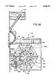
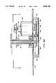
- FIGS. 1A and 1Bare schematic, partially cut-away, top views of an automated continuous manufacturing system in accordance with the present system
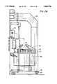
- FIGS. 2A and 2Bare schematic, partially cut-away front views of the system of FIGS. 1A and 1B, respectively;
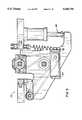
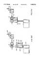
- FIGS. 3A and 3Bare top views of a removable station subassembly for the application of material to a work piece;
- FIGS. 4A and 4Bare side views of the sub-assembly of FIGS. 3A and 3B;
- FIG. 5is a partial end view of the subassembly of FIGS. 3A and 3B taken along the line 5--5;
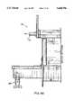
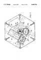
- FIGS. 6A and 6Bare schematic, partially cut-away, front views of a rotary drive mechanism for the present system taken along the line 6--6 of FIG. 2A;
- FIG. 7is a top view of the rotary drive mechanism of FIG. 6B taken along the line 7--7 of FIG. 6B;
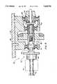
- FIG. 8is a schematic, enlarged, cut-away, side view of a clutch mechanism of the rotary drive mechanism shown in FIG. 6A;
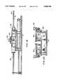
- FIGS. 9 and 10are press assembly stations for either the first or second work tables of the present system for holding the second work piece torsion bar for insertion of the first work piece bushing therein by the insertion subassembly;
- FIGS. 11 and 12are side and front views, respectively, of a position sensor of the assembly station of the present system
- FIGS. 13 and 14are side and front views, respectively, of an alternate embodiment of a position sensor of the assembly station of the present system
- FIGS. 15A-15Fare schematic representations showing movement of the work pieces around the work table to the various work stations, where FIG. 15A shows a work piece being loaded onto the work station, FIG. 15B shows rotation to a work station where the work pieces are claimed, FIG. 15C shows rotation to an idle work station, FIG. 15D shows rotation to a coating work station of the type shown in FIGS. 3A and 3B, FIG. 15E shows rotation to an idle work station, and FIG. 15F shows rotation to an assembly station;
- FIG. 15Gis a schematic, cut-away, side view of an orientation subassembly, removing subassembly and a work piece supported on a work piece support prior to transfer of the work piece to a press assembly, taken along the line 15G--15G of FIG. 15F;
- FIG. 15His a schematic, cut-away, side view of the system of FIG. 15G, with the orientation subassembly engaged surrounding the work piece;
- FIG. 15Iis a schematic, cut-away, side view of the system of FIG. 15H where the removing subassembly has transferred the work piece to the press assembly;
- FIG. 15Jis a schematic, cut-away, side view of the system of FIG. 15I, where the work piece is on the press assembly and the orientation and removing subassemblies are returned for the next work piece engagement;
- FIG. 15Kis a schematic, cut-away side view of the system of FIG. 15J, where the press assembly is pivoted for press fit engagement of the bushing work piece with the torsion bar second work piece;
- FIG. 15Lis a schematic, cut-away, side view of the system of FIG. 15K showing the press assembly press fitting the bushing into engagement within an end of the torsion bar;
- FIG. 15Mis a schematic, cut-away, side view of the system of FIG. 15L showing the press assembly retracted for the next work piece engagement, and the completed assembly;
- FIGS. 16A and 16Bare schematic, cut-away, front views of the press assembly of the present system
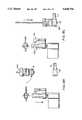
- FIG. 17is an exploded front view of the disposable cartridges of the reservoir dispensing assembly
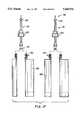
- FIG. 18is a front view of the multiple component coating material reservoir dispensing assembly
- FIG. 19is side view of the dispensing assembly of FIG. 18.
- FIG. 20is a partially cut-away end view of the dispensing assembly of FIG. 18 taken along the line 20--20.
- FIGS. 1A and 1Bare schematic, partial views of the present automated continuous manufacturing system for feeding, processing, aligning and assembling bushing work pieces to form a link assembly.
- the link assemblyincludes a bushing work piece B for engagement with a second work piece or torsion bar T.
- the torsion bar Tincludes support rings S on the first and second ends E, SE of the torsion bar.
- the manufacturing systemgenerally referred to at reference numeral 10, preferably includes first and second rotatable work tables 12a, 12b, a controller system 14 for controlling operation of the system, including the position and movement of bushing work pieces through the system 10, and a ventilation system 16 for reducing the risk of harmful vapors by containing and removing such vapors from the work tables 12a, 12b.
- the work tables 12a, 12bare enclosed by clear cover panels 24 which permit the operator to view the work tables during operation, while at the same time preventing exposure to moving parts or vapors from any materials being applied during operation.
- the covers 24are manufactured of a clear synthetic resin material, for example, Tempered Glass.
- the system 10is supported on a base frame 18 having hollow frame members 20 as shown in FIGS. 2A and 2B.
- the frame members 20are interconnected with the work tables, which are substantially closed to reduce the vapors escaping from the work tables 12 during operation.
- the frame members 20are also interconnected with ducts 22 which form a portion of the ventilation system 16 for vapor removal.
- the ventilation system 16includes an exhaust fan (not shown) which pulls ambient air into the work tables through openings 23 in the substantially closed work tables 12 and into the frame members and ducts, for removal through an appropriate exhaust vent (not shown).
- the ventilation system 16additionally enables control of any environmental exhaust requirements by exhausting the vapors exiting the system 10 at a specified and desired rate.
- the work table 12a, 12bincludes an upper support plate 26 and a lower support plate 28.
- the upper support plate 26supports a plurality of work stations 30, and a plurality of rotatable work piece supports 32 or spindle subassemblies which support individual bushings or work pieces B.
- the system 10includes 6 work stations and 6 work piece supports. The work piece supports 32 are rotated to each of the work stations 30 during operation of the system 10 to perform a variety of desired tasks on the work pieces B.
- the work piece supports 32are supported between an index plate 34 and the upper support plate 2b.
- the supports or spindle assemblies 32are secured to the underside of the index plate 34.
- Each work piece support 32includes a spindle block 36 which is secured to the index plate 34.
- the work piece supportsinclude a central shaft 38, which is mounted via conventional bearing assemblies 74 to the spindle block 36.
- the central shaft 38has an inner end 39 and an outer end 40, which is located adjacent the circumference of the work table. Removably inserted into the outer end 40 of the central shaft 38 is a spindle 42.
- the spindle 42is preferably a quick change part, meaning a part where each particular spindle is designed to support a particular bushing work piece B, and the spindle may be readily changed in the event the work table is to receive work pieces of a different configuration. Additional parts, as discussed below, may also be readily changed to accommodate a variety of different work pieces.
- the spindles 42are moved between work stations 30 by the manual initiation of the operator, using the foot pedal 25. Included on the spindle 42 is a magnetic slide member 43 used to maintain bushing work pieces on the spindle.
- the central shaft 38 and engaged spindle 42are rotated upon engagement of a pinion gear 44 attached on the inner end 39 of the central shaft 38.
- This constructionenables continuous rotation of each of the bushings or work pieces B while supported on the spindle 42. Such rotation is desirable in order to maintain any material applied to the surface of the work piece at the work station. Often, stopping the individual rotation of the work pieces results in material dripping from the bushing onto the work table, or in uneven coating of material on the surface of the work pieces. These disadvantages are avoided by such rotation.
- the pinion gear 44is driven by a rotary drive mechanism or drive train 45 which enables rotary operation of the system 10.
- the drive train 45is composed of a conventional AC fixed speed motor 46, which in the illustrated embodiment is a 1/3 HP explosion proof gear motor, coupled to a right angle gear reducer 48.
- the gear reducer 48drives, via a series of sprocket gears and a roller chain 50, a continuous motion shaft 52 which runs from the lower support plate 28 through the upper support plate 26.
- the roller chain 50 and sprocket gears 49also drive an input shaft 54 engaged with an index clutch 56. Upon pneumatic engagement by rotation of the input shaft 54, torque is transmitted to the output shaft 58 also engaged with the index clutch. This output shaft protrudes downward through the bottom plate 28. On this output shaft 58 the driver wheel 60 of a six station Geneva mechanism 62 is secured.
- the Geneva mechanism 62is a conventional device, illustrated in FIGS. 6B and 7, used to convert continuous rotary motion into intermittent rotary motion. Intermittent rotary motion is obtained upon rotation of a cam follower 64 on the driver wheel 60 through radial cut-outs 65 in a star wheel 66. After rotation of the star wheel 60 degrees, the cam follower 64 exists the cut-out 65 of the star wheel 66.
- the star wheel 66is then in a dwell position and locked in place by engaged semi-circular surfaces 68a, 68b on both the star and driver wheels, respectively.
- the mechanismis encased within a housing 70 and operates in an oil bath for wear reduction.
- the star wheel 66is secured to an index shaft 72 on a lower end 73.
- the index shaft 72rotates intermittently inside the continuous shaft 52.
- the pinion gearis rotated by the ring gear secured to the upper end of the continuous shaft.
- the pinion gearis disengaged from the hollow shaft by the release cam.
- the hollow shaftcan now be driven by the position drive discussed later.
- the pinion gearremains disengaged at station five.
- the circular index plate 34is attached to the top end of the index shaft.
- FIGS. 15A-15Fdemonstrate movement of the bushing to the various work stations.
- station 1FIG. 15A, bushings are loaded onto a non-rotating spindle, either manually by the operator, or automatically by a loading apparatus.
- bushingsare cleaned by the cleaning assembly 78, which is one of the removable station subassemblies 76, of the type illustrated in FIGS. 3A, 3B, 4A, 4B and 5.
- the cleaning assembly 78is substantially similar to one embodiment of the coating station and assembly 79, described below in connection with the illustrated embodiment of FIGS. 3A, 3B, 4A, 4B and 5, and is not structurally discussed in further detail. However, differences in functional considerations are set forth.
- the assemblies 78, 79consist of an air driven doctor roll 80 that rotates through a reservoir system which includes a solvent reservoir. Solvent is transferred to the roll 80 via an adjustable gap which controls the amount of coating material transferred, thus controlling the application thickness and minimizing runoff.
- the application roll speed and time of contactare variable and programmable.
- the illustrated reservoir system 82includes a coating material tank or pan 84 supported with the removable station subassembly 76, on a station plate 77.
- the tank 84is engaged with the station plate using an adjustment mechanism, generally referred to at reference numeral 88. Adjustment of the illustrated embodiment of the application system ensures that the work pieces B are provided with the desired amount of cleaning solvent or other coating material by positioning the tank to engage the rolls with the desired level of material.
- the adjustment mechanism 88enables vertical position adjustment of the application system.
- the tankis raised or lowered by manually actuating a spring operated calibrator using a pointer and scale.
- the scaleis secured to correspond to the position of the tank and the pointer.
- FIG. 15Cthe operation is idle. However, additional bushing functions may be added to accommodate any desired steps.
- an adhesive or other coating materialis applied.
- the coating assembly 79 at station 4(which is a removable work station subassembly 76) may be identical to the cleaning assembly of station 2, but coating the work piece with adhesive or other material instead of solvent.
- a dual component application system, or other system for applying a coating materialcould likewise be used.
- a dual component material application systemis used to coat the work pieces. The advantage of this system is that there is less coating material waste as well as improved control over the quality of the coating material, due to the fact that there is a reduction in the amount of time the coating material is exposed to the atmosphere.
- Reduced wasteis also obtained, since the system is better able to accurately dispense the coating material precisely where it is desired. By more accurately applying the coating material, cost savings are obtained due to reduced clean-up requirements. Additionally, the reduction in atmospheric exposure also assists with reducing the amount of vapors which are dispensed into the atmosphere. A reduction in vapors in the atmosphere further assists with improving safety concerns due to possible explosions from volatile materials.
- the illustrated system of FIGS. 17-20provides multiple component adhesive coating material to the rolls 80 for application to the work pieces.
- the systemincludes conventional disposable cartridges 85, shown in FIG. 17, containing various material components.
- the cartridges 85are interconnected to enable the combination of their respective components.
- Backflow preventers 81are included at the cartridge outlets 90 to assist with reducing the gravity feedback of different density components.
- Conventional static mixers 91are also provided such that once the material components are dispensed, they are further mixed prior to exiting the system at the outlet 92 for supply or application to either the bushing or rolls.
- the cartridges 85are secured together by retaining nuts 93, and secured within the assembly by a pivoting arm 94 secured by a conventional fastener 95.
- the adhesive componentsexit the cartridges 85 under pressure of a piston assembly 96.
- the piston assembly 96is driven by a conventional pneumatic cylinder 97 operated by the controller 14. Using the controller system, the piston assembly can be used to mix the desired amounts of the adhesive components. As shown in FIGS. 17 and 18, respectively, either a double or single dual cartridge assembly may be used, as needed.
- Fluid linesmay be used to extend from the static mixers for supply of the dispensed and mixed coating material to a further pinch valve for supply or application to either the bushing or rolls.
- the conventional pinch valverestricts the flow of fluid until opening of the valve via spring action. Upon being supplied with a signal from the controller, the pinch valve is opened and coating material is provided to the roll or work piece.
- This stationincorporates adhesive application to the outer edge of the flange that enters the link first at insertion. This adhesive actually coats the internal diameter of the link coupling thus eliminating the need for preswabbing the link with adhesive.
- the operationis idle, but may be adapted to provide an additional removable station subassembly for performing additional functions.
- a removing subassembly 102is provided for orienting the bushing and transferring the bushing to the press arbor for insertion into the link SE.
- Most bushings Beither have an identification lobe 112, shown in FIGS. 15G-15J, that must be aligned with the link SE when installed, or are eccentric with respect to the link, and must be installed in a predetermined radial position. This orientation is established by rotating the bushing B at the work station until the proper location is found, for example, when the identification lobe 112 is identified by an orientation subassembly 110.
- the illustrated orientation subassembly 110in FIGS. 11-12, and in an alternate embodiment 110' in FIGS. 13-14, includes a quick change release base member 114, which is adapted for easy attachment to a support member 115 by a release pin.
- the orientation subassembly 110is located adjacent the removing subassembly 102.
- Conventional fiber optic sensors 118are positioned on the release member which are interconnected with the controller. Once the identification lobe 112 interrupts the fiber optic sensor, the controller is signalled that the bushing is properly aligned, and rotation of the bushing is stopped. It should be understood that a variety of fiber optic sensor arrangements, as shown in FIGS. 13 and 14, may be used to accommodate a variety of work piece configurations.
- Each of the orientation and removing subassemblies 110, 102are supported on a base member 117, which is driven both vertically and horizontally by the remover driver 119.
- the removing assembly 102which includes a stripping mechanism 104, is used to transfer the bushing B from station 6 to the press or press arbor assembly station 140.
- the steps involved in removal of the bushing, and transfer to the press station 140are illustrated in FIGS. 15G-15L.
- the press assembly station 140includes an insertion subassembly 142, by which the bushing B is inserted into one of the link eyes SE.
- the press station 140includes a conventional servo motor 150 powered by a ball screw with variable and programmable velocity, force, acceleration, deceleration and final position.
- the insertion subassembly and press assemblyprovide a 2-axis mechanism which accepts bushings horizontally, rotates them to a vertical position, and then vertically inserts the bushing into the link eye.
- the final insertion position for installationis preprogrammed to a position within 0.0025 accuracy for each individual part. The operator will be able to manually change this position by a predetermined tolerance amount to compensate for temperature, humidity, etc., based on daily variations.
- FIGS. 9 and 10The base portions of alternate press assembly stations 140 are illustrated in FIGS. 9 and 10. Such base portions provide for maintaining the link or second work pieces SE during insertion of the bushing or first work piece B by the insertion subassembly 142. As shown in FIG. 9, a locking arm 147 is provided for securing the second work piece within the base portion.
- the base portion shown in FIG. 10provides a vise-like assembly 148 which operates using a pneumatic cylinder 149 to secure the second work piece.
- an induction heating device 146may be used in connection with the press arbor or press assembly 140 for rapid curing of the adhesive or other materials applied to the surface of the bushing B by the coating assembly 79.
- Such induction heating deviceshave the advantage of rapid, controlled heating which cures the desired material, without impacting the structure or materials of the bushing or work piece.
- the present inventionalso provides the additional advantage that the controller change over from different types of links can be accomplished in 5 minutes or less. As illustrated, the change over only requires removing various units out or unplugging the units and dropping or plugging in the next alternate unit.
- the removable station subassembly 76may be removed from a work station position by manually grasping the handle 75 and pulling the subassembly from the work table. All press motions and position variables are pre-programmed and may be automatically changed upon entering a part number on the operator panel of the control system 14.
Landscapes
- Engineering & Computer Science (AREA)
- Mechanical Engineering (AREA)
- Coating Apparatus (AREA)
Abstract
Description
Claims (19)
Priority Applications (3)
| Application Number | Priority Date | Filing Date | Title |
|---|---|---|---|
| US08/385,501US5640756A (en) | 1995-02-08 | 1995-02-08 | Manufacturing system |
| BR9607589ABR9607589A (en) | 1995-02-08 | 1996-02-01 | Automated continuous manufacturing system |
| PCT/US1996/001263WO1996024460A1 (en) | 1995-02-08 | 1996-02-01 | Manufacturing system |
Applications Claiming Priority (1)
| Application Number | Priority Date | Filing Date | Title |
|---|---|---|---|
| US08/385,501US5640756A (en) | 1995-02-08 | 1995-02-08 | Manufacturing system |
Publications (1)
| Publication Number | Publication Date |
|---|---|
| US5640756Atrue US5640756A (en) | 1997-06-24 |
Family
ID=23521647
Family Applications (1)
| Application Number | Title | Priority Date | Filing Date |
|---|---|---|---|
| US08/385,501Expired - Fee RelatedUS5640756A (en) | 1995-02-08 | 1995-02-08 | Manufacturing system |
Country Status (3)
| Country | Link |
|---|---|
| US (1) | US5640756A (en) |
| BR (1) | BR9607589A (en) |
| WO (1) | WO1996024460A1 (en) |
Cited By (25)
| Publication number | Priority date | Publication date | Assignee | Title |
|---|---|---|---|---|
| US6119330A (en)* | 1999-04-21 | 2000-09-19 | Cheng; Chin Chung | Fully automatic cutting metal-working machine |
| US6138342A (en)* | 1997-06-06 | 2000-10-31 | Kuze; Yoshikazu | Multi-stage assembling robot |
| US6412167B1 (en)* | 1999-07-20 | 2002-07-02 | Marzocchi S.P.A. | Apparatus for connecting a star cross piece to a leg of a bicycle or motorcycle fork |
| US6435397B2 (en) | 2000-04-18 | 2002-08-20 | Progressive Tool & Industries Co. | Robotic turntable |
| US6553656B1 (en)* | 1997-06-21 | 2003-04-29 | Feintool International Holding | Assembly or manufacturing robot and work station for the same |
| US6632720B2 (en)* | 2002-01-15 | 2003-10-14 | Cardiac Pacemakers, Inc. | Method of constructing a capacitor stack for a flat capacitor |
| US6662083B2 (en) | 2000-10-31 | 2003-12-09 | Progressive Tool & Industries Co. | Multiple robotic workstation with multiple fixtures |
| US20040019268A1 (en)* | 2000-11-03 | 2004-01-29 | Cardiac Pacemakers, Inc. | Configurations and methods for making capacitor connections |
| US20040095199A1 (en)* | 2002-11-13 | 2004-05-20 | Kozo Ono | Surface mount crystal unit and surface mount crystal oscillator |
| US20040127952A1 (en)* | 2002-12-31 | 2004-07-01 | O'phelan Michael J. | Batteries including a flat plate design |
| US6763265B2 (en) | 2000-11-03 | 2004-07-13 | Cardiac Pacemakers, Inc. | Method of constructing a capacitor stack for a flat capacitor |
| US20040147960A1 (en)* | 2000-11-03 | 2004-07-29 | Cardiac Pacemakers, Inc. | Flat capacitor for an implantable medical device |
| US20040174658A1 (en)* | 2000-11-03 | 2004-09-09 | Cardiac Pacemakers, Inc. | Implantable heart monitors having flat capacitors with curved profiles |
| US20040193221A1 (en)* | 2000-11-03 | 2004-09-30 | Cardiac Pacemakers, Inc. | Implantable heart monitors having capacitors with endcap headers |
| US6833987B1 (en) | 2000-11-03 | 2004-12-21 | Cardiac Pacemakers, Inc. | Flat capacitor having an active case |
| US20050019443A1 (en)* | 2003-03-17 | 2005-01-27 | Boyd Kathleen C. | Rotary injection molding apparatus and method for use |
| US20060023400A1 (en)* | 2004-07-16 | 2006-02-02 | Sherwood Gregory J | Method and apparatus for high voltage aluminum capacitor design |
| US7092694B2 (en)* | 2001-06-19 | 2006-08-15 | Koninklijke Philips Electronics N.V. | Wireless communication system having a guest transmitter and a host receiver |
| US20070294883A1 (en)* | 2006-06-01 | 2007-12-27 | Kioto Clear Energy Ag | Apparatus for the processing of photovoltaic cells |
| US7917207B2 (en) | 2005-04-29 | 2011-03-29 | Cardiac Pacemakers, Inc. | Method and apparatus for an implantable pulse generator with a stacked battery and capacitor |
| US8451587B2 (en) | 2000-11-03 | 2013-05-28 | Cardiac Pacemakers, Inc. | Method for interconnecting anodes and cathodes in a flat capacitor |
| US8543201B2 (en) | 2000-11-03 | 2013-09-24 | Cardiac Pacemakers, Inc. | Flat capacitor having staked foils and edge-connected connection members |
| US9093683B2 (en) | 2002-12-31 | 2015-07-28 | Cardiac Pacemakers, Inc. | Method and apparatus for porous insulative film for insulating energy source layers |
| US10518437B2 (en)* | 2016-03-24 | 2019-12-31 | Masonite Corporation | Wood door slab processing system, and related methods |
| DE102019130181A1 (en) | 2018-11-21 | 2020-05-28 | Fanuc America Corporation | CONTINUOUS MACHINE PROCESSING WITH ROBOT TABLE ADJUSTMENT OF A CLAMPING DEVICE |
Families Citing this family (1)
| Publication number | Priority date | Publication date | Assignee | Title |
|---|---|---|---|---|
| CN103009017A (en)* | 2013-01-21 | 2013-04-03 | 江苏省宿迁市方圆机械有限公司 | Automotive torsion rod spring pre-torsion process |
Citations (34)
| Publication number | Priority date | Publication date | Assignee | Title |
|---|---|---|---|---|
| US401950A (en)* | 1889-04-23 | Hypodermic syringe | ||
| US2094524A (en)* | 1936-12-28 | 1937-09-28 | George H Busch | Evacuating machine |
| US2865303A (en)* | 1954-10-22 | 1958-12-23 | Technicon Instr | Pumps |
| US2898859A (en)* | 1957-07-15 | 1959-08-11 | Ernest R Corneil | Flexible tube fluid measuring and controlling device |
| US3187951A (en)* | 1963-10-04 | 1965-06-08 | H V Hardman Co Inc | Caulking gun |
| US3232496A (en)* | 1964-07-01 | 1966-02-01 | United Shoe Machinery Corp | Mastic dispensing devices |
| US3279505A (en)* | 1962-05-16 | 1966-10-18 | Renz Wacker & Co | Apparatus for welding bimetallic contacts |
| US3302832A (en)* | 1965-04-15 | 1967-02-07 | H V Hardman Co Inc | Caulking gun |
| US3437050A (en)* | 1966-01-10 | 1969-04-08 | Ceskoslovenska Akademie Ved | Peristaltic pumping device |
| US3679331A (en)* | 1970-04-24 | 1972-07-25 | Delta Scient Corp | Metering pump and valve |
| US3935885A (en)* | 1974-02-01 | 1976-02-03 | Alter Richard R | Capsule-filling machines |
| US3970120A (en)* | 1974-12-20 | 1976-07-20 | Smithkline Corporation | Filling machine |
| US4067479A (en)* | 1975-07-31 | 1978-01-10 | Products Research & Chemical Corporation | Two part material meter-mix dispenser apparatus |
| US4152566A (en)* | 1976-10-13 | 1979-05-01 | Maegerle Karl | Apparatus for manufacturing an article |
| US4273260A (en)* | 1978-02-03 | 1981-06-16 | Bush George E | Dispensing of fluent materials |
| US4373129A (en)* | 1978-07-03 | 1983-02-08 | General Electric Company | Apparatus for assembling and welding vented cell covers |
| US4449289A (en)* | 1980-07-28 | 1984-05-22 | General Electric Company | Automatic system and method for compressing coil turns and inserting insulators in slots of a slotted stator core |
| US4547136A (en)* | 1984-11-05 | 1985-10-15 | Manostat Corporation | Variable displacement peristaltic pump |
| DE3413255A1 (en)* | 1984-04-07 | 1985-10-17 | Krone Gmbh, 1000 Berlin | Method and apparatus for a modular flexible assembly system |
| US4602417A (en)* | 1983-10-24 | 1986-07-29 | Trw Inc. | Interconnector attachment machine |
| US4620359A (en)* | 1983-11-14 | 1986-11-04 | Charlton Associates | Apparatus for manufacturing rigid computer memory disc substrates |
| US4676410A (en)* | 1985-04-20 | 1987-06-30 | Hilti Aktiengesellschaft | Device for dispensing the contents of cartridges |
| US4690306A (en)* | 1985-08-12 | 1987-09-01 | Ciba-Geigy Corporation | Dispensing device for storing and applying at least one liquid or pasty substance |
| DE8714508U1 (en)* | 1987-10-31 | 1987-12-17 | Braungart Präzisionsmaschinen GmbH, 7730 Villingen-Schwenningen | Rotary indexing table machining center |
| US4874368A (en)* | 1988-07-25 | 1989-10-17 | Micromedics, Inc. | Fibrin glue delivery system |
| US4986443A (en)* | 1988-07-13 | 1991-01-22 | Gurit-Essex Ag | Method of discharging a substance from a cartridge and an apparatus for carrying out the method |
| US5031295A (en)* | 1989-11-09 | 1991-07-16 | Hoppmann Corporation | Multi-purpose turret assembly |
| US5038463A (en)* | 1988-03-17 | 1991-08-13 | Honda Giken Kogyo Kabushiki Kaisha | Apparatus for assembling a vehicular drive shaft |
| US5215215A (en)* | 1990-03-17 | 1993-06-01 | Varta Batterie Aktiengesellschaft | Method and apparatus for introducing viscous active ingredients into the case of galvanic cell |
| US5217146A (en)* | 1991-04-03 | 1993-06-08 | Wilhelm Hedrich Vakumanlagen GmbH & Co. KG | Device for filling one or more molds with flowable materials |
| US5249709A (en)* | 1989-10-16 | 1993-10-05 | Plas-Pak Industries, Inc. | Cartridge system for dispensing predetermined ratios of semi-liquid materials |
| US5257917A (en)* | 1992-10-02 | 1993-11-02 | Cole-Parmer Instrument Company | Peristaltic pump having means for reducing flow pulsation |
| US5282396A (en)* | 1992-12-10 | 1994-02-01 | U.S. Farathane Corporation | Link assembly |
| US5490322A (en)* | 1994-05-05 | 1996-02-13 | Chromalloy Gas Turbine Corporation | Gas turbine engine vane assembly repair apparatus |
Family Cites Families (7)
| Publication number | Priority date | Publication date | Assignee | Title |
|---|---|---|---|---|
| US3641653A (en)* | 1969-08-15 | 1972-02-15 | Matsushita Electric Industrial Co Ltd | Apparatus for automatic assembly of a rotor and the like |
| FR2490528A1 (en)* | 1980-08-28 | 1982-03-26 | Bailly Assemblages Roland | MECHANIZED WORKSTATION FOR ASSEMBLING COMPLETE PRODUCTS IN REPETITION |
| JPS58217238A (en)* | 1982-06-11 | 1983-12-17 | Pentel Kk | Assembly equipment for tubes and parts |
| JPS60141534A (en)* | 1983-12-28 | 1985-07-26 | Toyoda Gosei Co Ltd | Manufacturing method of anti-vibration rubber with metal housing |
| JPS63134141A (en)* | 1986-11-20 | 1988-06-06 | Ckd Corp | Multi-unit automatic working device of rotary table type |
| US4791715A (en)* | 1987-04-03 | 1988-12-20 | Cimco, Inc. | Method and apparatus for assembly of cassette pulley |
| JPH02296400A (en)* | 1989-05-11 | 1990-12-06 | Nippondenso Co Ltd | Odd shaped component automatic mounting device |
- 1995
- 1995-02-08USUS08/385,501patent/US5640756A/ennot_activeExpired - Fee Related
- 1996
- 1996-02-01WOPCT/US1996/001263patent/WO1996024460A1/enactiveApplication Filing
- 1996-02-01BRBR9607589Apatent/BR9607589A/ennot_activeApplication Discontinuation
Patent Citations (34)
| Publication number | Priority date | Publication date | Assignee | Title |
|---|---|---|---|---|
| US401950A (en)* | 1889-04-23 | Hypodermic syringe | ||
| US2094524A (en)* | 1936-12-28 | 1937-09-28 | George H Busch | Evacuating machine |
| US2865303A (en)* | 1954-10-22 | 1958-12-23 | Technicon Instr | Pumps |
| US2898859A (en)* | 1957-07-15 | 1959-08-11 | Ernest R Corneil | Flexible tube fluid measuring and controlling device |
| US3279505A (en)* | 1962-05-16 | 1966-10-18 | Renz Wacker & Co | Apparatus for welding bimetallic contacts |
| US3187951A (en)* | 1963-10-04 | 1965-06-08 | H V Hardman Co Inc | Caulking gun |
| US3232496A (en)* | 1964-07-01 | 1966-02-01 | United Shoe Machinery Corp | Mastic dispensing devices |
| US3302832A (en)* | 1965-04-15 | 1967-02-07 | H V Hardman Co Inc | Caulking gun |
| US3437050A (en)* | 1966-01-10 | 1969-04-08 | Ceskoslovenska Akademie Ved | Peristaltic pumping device |
| US3679331A (en)* | 1970-04-24 | 1972-07-25 | Delta Scient Corp | Metering pump and valve |
| US3935885A (en)* | 1974-02-01 | 1976-02-03 | Alter Richard R | Capsule-filling machines |
| US3970120A (en)* | 1974-12-20 | 1976-07-20 | Smithkline Corporation | Filling machine |
| US4067479A (en)* | 1975-07-31 | 1978-01-10 | Products Research & Chemical Corporation | Two part material meter-mix dispenser apparatus |
| US4152566A (en)* | 1976-10-13 | 1979-05-01 | Maegerle Karl | Apparatus for manufacturing an article |
| US4273260A (en)* | 1978-02-03 | 1981-06-16 | Bush George E | Dispensing of fluent materials |
| US4373129A (en)* | 1978-07-03 | 1983-02-08 | General Electric Company | Apparatus for assembling and welding vented cell covers |
| US4449289A (en)* | 1980-07-28 | 1984-05-22 | General Electric Company | Automatic system and method for compressing coil turns and inserting insulators in slots of a slotted stator core |
| US4602417A (en)* | 1983-10-24 | 1986-07-29 | Trw Inc. | Interconnector attachment machine |
| US4620359A (en)* | 1983-11-14 | 1986-11-04 | Charlton Associates | Apparatus for manufacturing rigid computer memory disc substrates |
| DE3413255A1 (en)* | 1984-04-07 | 1985-10-17 | Krone Gmbh, 1000 Berlin | Method and apparatus for a modular flexible assembly system |
| US4547136A (en)* | 1984-11-05 | 1985-10-15 | Manostat Corporation | Variable displacement peristaltic pump |
| US4676410A (en)* | 1985-04-20 | 1987-06-30 | Hilti Aktiengesellschaft | Device for dispensing the contents of cartridges |
| US4690306A (en)* | 1985-08-12 | 1987-09-01 | Ciba-Geigy Corporation | Dispensing device for storing and applying at least one liquid or pasty substance |
| DE8714508U1 (en)* | 1987-10-31 | 1987-12-17 | Braungart Präzisionsmaschinen GmbH, 7730 Villingen-Schwenningen | Rotary indexing table machining center |
| US5038463A (en)* | 1988-03-17 | 1991-08-13 | Honda Giken Kogyo Kabushiki Kaisha | Apparatus for assembling a vehicular drive shaft |
| US4986443A (en)* | 1988-07-13 | 1991-01-22 | Gurit-Essex Ag | Method of discharging a substance from a cartridge and an apparatus for carrying out the method |
| US4874368A (en)* | 1988-07-25 | 1989-10-17 | Micromedics, Inc. | Fibrin glue delivery system |
| US5249709A (en)* | 1989-10-16 | 1993-10-05 | Plas-Pak Industries, Inc. | Cartridge system for dispensing predetermined ratios of semi-liquid materials |
| US5031295A (en)* | 1989-11-09 | 1991-07-16 | Hoppmann Corporation | Multi-purpose turret assembly |
| US5215215A (en)* | 1990-03-17 | 1993-06-01 | Varta Batterie Aktiengesellschaft | Method and apparatus for introducing viscous active ingredients into the case of galvanic cell |
| US5217146A (en)* | 1991-04-03 | 1993-06-08 | Wilhelm Hedrich Vakumanlagen GmbH & Co. KG | Device for filling one or more molds with flowable materials |
| US5257917A (en)* | 1992-10-02 | 1993-11-02 | Cole-Parmer Instrument Company | Peristaltic pump having means for reducing flow pulsation |
| US5282396A (en)* | 1992-12-10 | 1994-02-01 | U.S. Farathane Corporation | Link assembly |
| US5490322A (en)* | 1994-05-05 | 1996-02-13 | Chromalloy Gas Turbine Corporation | Gas turbine engine vane assembly repair apparatus |
Cited By (58)
| Publication number | Priority date | Publication date | Assignee | Title |
|---|---|---|---|---|
| US6138342A (en)* | 1997-06-06 | 2000-10-31 | Kuze; Yoshikazu | Multi-stage assembling robot |
| US6553656B1 (en)* | 1997-06-21 | 2003-04-29 | Feintool International Holding | Assembly or manufacturing robot and work station for the same |
| US6119330A (en)* | 1999-04-21 | 2000-09-19 | Cheng; Chin Chung | Fully automatic cutting metal-working machine |
| US6412167B1 (en)* | 1999-07-20 | 2002-07-02 | Marzocchi S.P.A. | Apparatus for connecting a star cross piece to a leg of a bicycle or motorcycle fork |
| US6435397B2 (en) | 2000-04-18 | 2002-08-20 | Progressive Tool & Industries Co. | Robotic turntable |
| US6651867B2 (en) | 2000-04-18 | 2003-11-25 | Progressive Tool & Industries Co. | Robotic turntable |
| US6662083B2 (en) | 2000-10-31 | 2003-12-09 | Progressive Tool & Industries Co. | Multiple robotic workstation with multiple fixtures |
| US7157671B2 (en) | 2000-11-03 | 2007-01-02 | Cardiac Pacemakers, Inc. | Flat capacitor for an implantable medical device |
| US6957103B2 (en) | 2000-11-03 | 2005-10-18 | Cardiac Pacemakers, Inc. | Configurations and methods for making capacitor connections |
| US20040147960A1 (en)* | 2000-11-03 | 2004-07-29 | Cardiac Pacemakers, Inc. | Flat capacitor for an implantable medical device |
| US8543201B2 (en) | 2000-11-03 | 2013-09-24 | Cardiac Pacemakers, Inc. | Flat capacitor having staked foils and edge-connected connection members |
| US8744575B2 (en) | 2000-11-03 | 2014-06-03 | Cardiac Pacemakers, Inc. | Flat capacitor for an implantable medical device |
| US20040174658A1 (en)* | 2000-11-03 | 2004-09-09 | Cardiac Pacemakers, Inc. | Implantable heart monitors having flat capacitors with curved profiles |
| US20040193221A1 (en)* | 2000-11-03 | 2004-09-30 | Cardiac Pacemakers, Inc. | Implantable heart monitors having capacitors with endcap headers |
| US6833987B1 (en) | 2000-11-03 | 2004-12-21 | Cardiac Pacemakers, Inc. | Flat capacitor having an active case |
| US9443660B2 (en) | 2000-11-03 | 2016-09-13 | Cardiac Pacemakers, Inc. | Flat capacitor for an implantable medical device |
| US7576973B2 (en) | 2000-11-03 | 2009-08-18 | Cardiac Pacemakers, Inc. | Configurations and methods for making capacitor connections |
| US7355841B1 (en) | 2000-11-03 | 2008-04-08 | Cardiac Pacemakers, Inc. | Configurations and methods for making capacitor connections |
| US20050052825A1 (en)* | 2000-11-03 | 2005-03-10 | Cardiac Pacemakers, Inc. | Flat capacitor having an active case |
| US6885887B2 (en) | 2000-11-03 | 2005-04-26 | Cardiac Pacemakers, Inc. | Method of constructing a capacitor stack for a flat capacitor |
| US6763265B2 (en) | 2000-11-03 | 2004-07-13 | Cardiac Pacemakers, Inc. | Method of constructing a capacitor stack for a flat capacitor |
| US6985351B2 (en) | 2000-11-03 | 2006-01-10 | Cardiac Pacemakers, Inc. | Implantable heart monitors having flat capacitors with curved profiles |
| US20060009808A1 (en)* | 2000-11-03 | 2006-01-12 | Cardiac Pacemakers, Inc. | Configurations and methods for making capicitor connections |
| US20080030928A1 (en)* | 2000-11-03 | 2008-02-07 | Cardiac Pacemakers, Inc. | Configurations and methods for making capacitor connections |
| US7072713B2 (en) | 2000-11-03 | 2006-07-04 | Cardiac Pacemakers, Inc. | Flat capacitor for an implantable medical device |
| US10032565B2 (en) | 2000-11-03 | 2018-07-24 | Cardiac Pacemakers, Inc. | Flat capacitor for an implantable medical device |
| US8451587B2 (en) | 2000-11-03 | 2013-05-28 | Cardiac Pacemakers, Inc. | Method for interconnecting anodes and cathodes in a flat capacitor |
| US7154739B2 (en) | 2000-11-03 | 2006-12-26 | Cardiac Pacemakers, Inc. | Flat capacitor having an active case |
| US20040019268A1 (en)* | 2000-11-03 | 2004-01-29 | Cardiac Pacemakers, Inc. | Configurations and methods for making capacitor connections |
| US7190569B2 (en) | 2000-11-03 | 2007-03-13 | Cardiac Pacemakers, Inc. | Implantable heart monitors having capacitors with endcap headers |
| US7190570B2 (en) | 2000-11-03 | 2007-03-13 | Cardiac Pacemakers, Inc. | Configurations and methods for making capacitor connections |
| US7092694B2 (en)* | 2001-06-19 | 2006-08-15 | Koninklijke Philips Electronics N.V. | Wireless communication system having a guest transmitter and a host receiver |
| US7089982B2 (en) | 2002-01-15 | 2006-08-15 | Cardiac Pacemakers, Inc. | Apparatus for constructing a capacitor stack for a flat capacitor |
| US20040029302A1 (en)* | 2002-01-15 | 2004-02-12 | Cardiac Pacemakers, Inc. | Apparatus for constructing a capacitor stack for a flat capacitor |
| US6632720B2 (en)* | 2002-01-15 | 2003-10-14 | Cardiac Pacemakers, Inc. | Method of constructing a capacitor stack for a flat capacitor |
| US20040095199A1 (en)* | 2002-11-13 | 2004-05-20 | Kozo Ono | Surface mount crystal unit and surface mount crystal oscillator |
| US9620806B2 (en) | 2002-12-31 | 2017-04-11 | Cardiac Pacemakers, Inc. | Batteries including a flat plate design |
| US10115995B2 (en) | 2002-12-31 | 2018-10-30 | Cardiac Pacemakers, Inc. | Batteries including a flat plate design |
| US7479349B2 (en) | 2002-12-31 | 2009-01-20 | Cardiac Pacemakers, Inc. | Batteries including a flat plate design |
| US20040127952A1 (en)* | 2002-12-31 | 2004-07-01 | O'phelan Michael J. | Batteries including a flat plate design |
| US20100203380A1 (en)* | 2002-12-31 | 2010-08-12 | O'phelan Michael J | Batteries including a flat plate design |
| US9093683B2 (en) | 2002-12-31 | 2015-07-28 | Cardiac Pacemakers, Inc. | Method and apparatus for porous insulative film for insulating energy source layers |
| US20050019443A1 (en)* | 2003-03-17 | 2005-01-27 | Boyd Kathleen C. | Rotary injection molding apparatus and method for use |
| US20080174048A1 (en)* | 2003-03-17 | 2008-07-24 | Vmi Epe Holland Bv | Rotary Injection Molding Apparatus and Method for Use |
| US7798798B2 (en) | 2003-03-17 | 2010-09-21 | Vmi Holland B.V. | Rotary injection molding apparatus and method for use |
| US20070162077A1 (en)* | 2004-07-16 | 2007-07-12 | Cardiac Pacemakers, Inc. | Method and apparatus for high voltage aluminum capacitor design |
| US8465555B2 (en) | 2004-07-16 | 2013-06-18 | Cardiac Pacemakers, Inc. | Method and apparatus for high voltage aluminum capacitor design |
| US8133286B2 (en) | 2004-07-16 | 2012-03-13 | Cardiac Pacemakers, Inc. | Method and apparatus for high voltage aluminum capacitor design |
| US7224575B2 (en) | 2004-07-16 | 2007-05-29 | Cardiac Pacemakers, Inc. | Method and apparatus for high voltage aluminum capacitor design |
| US20060023400A1 (en)* | 2004-07-16 | 2006-02-02 | Sherwood Gregory J | Method and apparatus for high voltage aluminum capacitor design |
| US8406882B2 (en) | 2005-04-29 | 2013-03-26 | Cardiac Pacemakers, Inc. | Implantable pulse generator with a stacked battery and capacitor |
| US8055346B2 (en) | 2005-04-29 | 2011-11-08 | Cardiac Pacemakers, Inc. | Implantable pulse generator with a stacked battery and capacitor |
| US20110160812A1 (en)* | 2005-04-29 | 2011-06-30 | Youker Nick A | Implantable pulse generator with a stacked battery and capacitor |
| US7917207B2 (en) | 2005-04-29 | 2011-03-29 | Cardiac Pacemakers, Inc. | Method and apparatus for an implantable pulse generator with a stacked battery and capacitor |
| US20070294883A1 (en)* | 2006-06-01 | 2007-12-27 | Kioto Clear Energy Ag | Apparatus for the processing of photovoltaic cells |
| US10518437B2 (en)* | 2016-03-24 | 2019-12-31 | Masonite Corporation | Wood door slab processing system, and related methods |
| DE102019130181A1 (en) | 2018-11-21 | 2020-05-28 | Fanuc America Corporation | CONTINUOUS MACHINE PROCESSING WITH ROBOT TABLE ADJUSTMENT OF A CLAMPING DEVICE |
| US11163295B2 (en) | 2018-11-21 | 2021-11-02 | Fanuc America Corporation | Continuous machining with robotic table tracking of fixture |
Also Published As
| Publication number | Publication date |
|---|---|
| BR9607589A (en) | 1998-07-07 |
| WO1996024460A1 (en) | 1996-08-15 |
Similar Documents
| Publication | Publication Date | Title |
|---|---|---|
| US5640756A (en) | Manufacturing system | |
| US5183509A (en) | Apparatus for application of a material to an internal surface of items of manufacture | |
| US7410541B2 (en) | Roll coater assembly system | |
| US20090101068A1 (en) | Roll Coater Assembly System | |
| US20090126630A1 (en) | Spindle Spray Coating System | |
| JP2019520247A (en) | Decorator drive and printing plate cylinder automation | |
| US4225638A (en) | Method and apparatus for flow coating with suck-back control | |
| AU727160B2 (en) | Spindle disc for high speed can decorators | |
| US4479429A (en) | Multi-color printing apparatus of surfaces of bodies of rotation | |
| US3645201A (en) | Multicolor printing machine cylindrical and frustoconical objects | |
| US4493857A (en) | Method for applying a coating to a thin board | |
| EP0134158B1 (en) | Base coat applicator | |
| CN111886079B (en) | Lubricant spraying device and lubricant application method for treating the inner surface of an insertion and assembly aid at a packaging station | |
| JPH07237745A (en) | Container holding tool for different diameter container | |
| US6887333B1 (en) | System and method for environmentally cleaning a package for a heat transfer decorating machine | |
| EP0559946A1 (en) | Cap application and tightening apparatus for trigger pump vessel | |
| CN217750230U (en) | Automatic assembly machine | |
| CN110918370B (en) | Automatic wipe treatment agent equipment | |
| EP0476516A1 (en) | Flexographic or indirect rotogravure printing machine | |
| DE29716464U1 (en) | Machine for equipping vessels | |
| US20240351329A1 (en) | Can decorator and plate cylinder locking mechanism, replacement system, and timing adjustment system and method therefor | |
| SU1235546A1 (en) | Apparatus for applying a coating on plates | |
| JPS63232868A (en) | Continuous coating device | |
| DE19962308A1 (en) | Conveyor belt used in automatic machinery packaging adhesive blocks, has sheet parting agent attached to it | |
| JP3645943B2 (en) | Method and apparatus for coating inner surface of cylindrical workpiece |
Legal Events
| Date | Code | Title | Description |
|---|---|---|---|
| AS | Assignment | Owner name:GENCORP INC., OHIO Free format text:ASSIGNMENT OF ASSIGNORS INTEREST;ASSIGNORS:MILLER, MAX J. JR;BROWN, ROBERT L.;MCDONALD, JAMES J.;AND OTHERS;REEL/FRAME:007606/0699;SIGNING DATES FROM 19950310 TO 19950329 | |
| FPAY | Fee payment | Year of fee payment:4 | |
| AS | Assignment | Owner name:DEUTSCHE BANK TRUST COMPANY AMERICAS, (FORMERLY KN Free format text:ASSIGNMENT OF SECURITY INTEREST IN US TRADEMARKS AND PATENTS;ASSIGNOR:GENCORP INC.;REEL/FRAME:013386/0934 Effective date:20021002 | |
| REMI | Maintenance fee reminder mailed | ||
| AS | Assignment | Owner name:WACHOVIA BANK, NATIONAL ASSOCIATION, AS ADMINISTRA Free format text:NOTICE OF GRANT OF SECURITY INTEREST;ASSIGNOR:GENCORP INC.;REEL/FRAME:015766/0718 Effective date:20041206 | |
| AS | Assignment | Owner name:GENCORP INC., CALIFORNIA Free format text:RELEASE OF SECURITY INTEREST;ASSIGNOR:DEUTSCHE BANK TRUST COMPANY AMERICAS;REEL/FRAME:015778/0549 Effective date:20041206 | |
| LAPS | Lapse for failure to pay maintenance fees | ||
| STCH | Information on status: patent discontinuation | Free format text:PATENT EXPIRED DUE TO NONPAYMENT OF MAINTENANCE FEES UNDER 37 CFR 1.362 | |
| FP | Lapsed due to failure to pay maintenance fee | Effective date:20050624 |