US5640007A - Optical encoder comprising a plurality of encoder wheels - Google Patents
Optical encoder comprising a plurality of encoder wheelsDownload PDFInfo
- Publication number
- US5640007A US5640007AUS08/493,271US49327195AUS5640007AUS 5640007 AUS5640007 AUS 5640007AUS 49327195 AUS49327195 AUS 49327195AUS 5640007 AUS5640007 AUS 5640007A
- Authority
- US
- United States
- Prior art keywords
- encoder
- absolute
- teeth
- wheels
- code sequences
- Prior art date
- Legal status (The legal status is an assumption and is not a legal conclusion. Google has not performed a legal analysis and makes no representation as to the accuracy of the status listed.)
- Expired - Lifetime
Links
- 230000003287optical effectEffects0.000title1
- 238000012544monitoring processMethods0.000claimsdescription20
- 238000000926separation methodMethods0.000claimsdescription19
- 239000000463materialSubstances0.000claimsdescription12
- 238000012545processingMethods0.000claimsdescription10
- 239000011248coating agentSubstances0.000claims1
- 238000000576coating methodMethods0.000claims1
- 238000006073displacement reactionMethods0.000abstractdescription5
- 230000007246mechanismEffects0.000abstractdescription4
- 230000008859changeEffects0.000description10
- 238000000034methodMethods0.000description7
- 230000008901benefitEffects0.000description6
- 239000011347resinSubstances0.000description5
- 229920005989resinPolymers0.000description5
- PXHVJJICTQNCMI-UHFFFAOYSA-NNickelChemical compound[Ni]PXHVJJICTQNCMI-UHFFFAOYSA-N0.000description4
- 230000008569processEffects0.000description4
- 229920013683CelanesePolymers0.000description3
- 238000004519manufacturing processMethods0.000description3
- 229920001169thermoplasticPolymers0.000description3
- 229920001187thermosetting polymerPolymers0.000description3
- 239000004416thermosoftening plasticSubstances0.000description3
- 229920005123Celcon®Polymers0.000description2
- 238000007796conventional methodMethods0.000description2
- 238000010586diagramMethods0.000description2
- 238000002347injectionMethods0.000description2
- 239000007924injectionSubstances0.000description2
- 238000001746injection mouldingMethods0.000description2
- 229910052759nickelInorganic materials0.000description2
- 230000002093peripheral effectEffects0.000description2
- 239000004033plasticSubstances0.000description2
- 229920003023plasticPolymers0.000description2
- 230000000630rising effectEffects0.000description2
- 229910001220stainless steelInorganic materials0.000description2
- 239000010935stainless steelSubstances0.000description2
- 229920000443XenoyPolymers0.000description1
- 230000007812deficiencyEffects0.000description1
- 238000001514detection methodMethods0.000description1
- 230000023077detection of light stimulusEffects0.000description1
- 230000000694effectsEffects0.000description1
- 230000014759maintenance of locationEffects0.000description1
- 239000000203mixtureSubstances0.000description1
- 238000012986modificationMethods0.000description1
- 230000004048modificationEffects0.000description1
- 238000007747platingMethods0.000description1
- 230000001105regulatory effectEffects0.000description1
- 230000007704transitionEffects0.000description1
Images


Classifications
- G—PHYSICS
- G01—MEASURING; TESTING
- G01D—MEASURING NOT SPECIALLY ADAPTED FOR A SPECIFIC VARIABLE; ARRANGEMENTS FOR MEASURING TWO OR MORE VARIABLES NOT COVERED IN A SINGLE OTHER SUBCLASS; TARIFF METERING APPARATUS; MEASURING OR TESTING NOT OTHERWISE PROVIDED FOR
- G01D5/00—Mechanical means for transferring the output of a sensing member; Means for converting the output of a sensing member to another variable where the form or nature of the sensing member does not constrain the means for converting; Transducers not specially adapted for a specific variable
- G01D5/26—Mechanical means for transferring the output of a sensing member; Means for converting the output of a sensing member to another variable where the form or nature of the sensing member does not constrain the means for converting; Transducers not specially adapted for a specific variable characterised by optical transfer means, i.e. using infrared, visible, or ultraviolet light
- G01D5/32—Mechanical means for transferring the output of a sensing member; Means for converting the output of a sensing member to another variable where the form or nature of the sensing member does not constrain the means for converting; Transducers not specially adapted for a specific variable characterised by optical transfer means, i.e. using infrared, visible, or ultraviolet light with attenuation or whole or partial obturation of beams of light
- G01D5/34—Mechanical means for transferring the output of a sensing member; Means for converting the output of a sensing member to another variable where the form or nature of the sensing member does not constrain the means for converting; Transducers not specially adapted for a specific variable characterised by optical transfer means, i.e. using infrared, visible, or ultraviolet light with attenuation or whole or partial obturation of beams of light the beams of light being detected by photocells
- G01D5/347—Mechanical means for transferring the output of a sensing member; Means for converting the output of a sensing member to another variable where the form or nature of the sensing member does not constrain the means for converting; Transducers not specially adapted for a specific variable characterised by optical transfer means, i.e. using infrared, visible, or ultraviolet light with attenuation or whole or partial obturation of beams of light the beams of light being detected by photocells using displacement encoding scales
- G01D5/3473—Circular or rotary encoders
- G—PHYSICS
- G01—MEASURING; TESTING
- G01D—MEASURING NOT SPECIALLY ADAPTED FOR A SPECIFIC VARIABLE; ARRANGEMENTS FOR MEASURING TWO OR MORE VARIABLES NOT COVERED IN A SINGLE OTHER SUBCLASS; TARIFF METERING APPARATUS; MEASURING OR TESTING NOT OTHERWISE PROVIDED FOR
- G01D5/00—Mechanical means for transferring the output of a sensing member; Means for converting the output of a sensing member to another variable where the form or nature of the sensing member does not constrain the means for converting; Transducers not specially adapted for a specific variable
- G01D5/26—Mechanical means for transferring the output of a sensing member; Means for converting the output of a sensing member to another variable where the form or nature of the sensing member does not constrain the means for converting; Transducers not specially adapted for a specific variable characterised by optical transfer means, i.e. using infrared, visible, or ultraviolet light
- G01D5/32—Mechanical means for transferring the output of a sensing member; Means for converting the output of a sensing member to another variable where the form or nature of the sensing member does not constrain the means for converting; Transducers not specially adapted for a specific variable characterised by optical transfer means, i.e. using infrared, visible, or ultraviolet light with attenuation or whole or partial obturation of beams of light
- G01D5/34—Mechanical means for transferring the output of a sensing member; Means for converting the output of a sensing member to another variable where the form or nature of the sensing member does not constrain the means for converting; Transducers not specially adapted for a specific variable characterised by optical transfer means, i.e. using infrared, visible, or ultraviolet light with attenuation or whole or partial obturation of beams of light the beams of light being detected by photocells
- G01D5/347—Mechanical means for transferring the output of a sensing member; Means for converting the output of a sensing member to another variable where the form or nature of the sensing member does not constrain the means for converting; Transducers not specially adapted for a specific variable characterised by optical transfer means, i.e. using infrared, visible, or ultraviolet light with attenuation or whole or partial obturation of beams of light the beams of light being detected by photocells using displacement encoding scales
- G01D5/34776—Absolute encoders with analogue or digital scales
- G01D5/34792—Absolute encoders with analogue or digital scales with only digital scales or both digital and incremental scales
Definitions
- the present inventionrelates generally to rotary position sensors, and more particularly to encoders which provide digital representation of angular position.
- a rotary actuatorsuch as a valve actuator
- position sensing of a rotary memberhas been accomplished through use of cam operated switches and/or potentiometers.
- Absolute encodersare also known which provide a digital representation corresponding to the rotary position.
- Absolute encodersutilize a sensing mechanism which evaluates rotary displacement relative to a measuring scale. For sensing rotary displacement, the scale is in the form of one or more disks that rotate a plurality of concentric tracks providing respective bits of a multi-bit digital code.
- the code tracksare typically formed of optically responsive segments which are etched, painted, drilled, or otherwise modified on the rotating disk.
- absolute encodershave the property that the operating power can be removed without loss of the data corresponding to rotary position since the data is carried by the encoder itself.
- absolute encodersrequire a great many parallel scales, the exact number depending upon the range and accuracy requirements. This large number of scales required in absolute encoders causes them to be more delicate in application as well as less reliable. However, in many applications, the reliability and ruggedness are extremely important features. Furthermore, the cost of the typical absolute encoder is rather high for these same reasons. Accordingly, the present invention has been developed in view of the foregoing and to overcome the deficiencies of the prior art.
- the present inventionprovides an absolute encoder of improved accuracy and low cost not found in the prior art.
- the absolute encoder of the present inventionincludes a plurality of rotatably mounted encoder wheels. Each encoder wheel includes at least one code sequence extending concentrically around the encoder wheel.
- the absolute encoder of the present inventionalso includes means provided between each pair of encoder wheels which operates to rotate the second encoder wheel of the pair a predetermined amount following a predetermined amount of rotation of the first encoder wheel of the pair.
- Sensing meansare also included which comprise light emitting means and detector means.
- the light emitting meansis adapted to illuminate a defined region of the code sequence.
- the detector meansis adapted to identify light which is illuminated by the light emitting means relative to the defined region of the code sequence.
- Another object of the present inventionis to provide a novel encoder which is of improved accuracy and reliability, and which can be provided at low cost.
- Still another object of the present inventionis to provide an improved absolute encoder capable of accurately sensing displacement of a rotary shaft and which is inexpensive to manufacture and assemble.
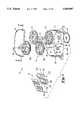
- FIG. 1is an exploded perspective view illustrating an embodiment of the absolute encoder of the present invention
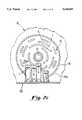
- FIG. 2ais a sectional front elevational view of the absolute encoder illustrated in FIG. 1; taken along the line A--A and showing an encoder wheel assembly;
- FIG. 2bis a sectional side elevational view of the absolute encoder illustrated in FIG. 1 taken along the line B--B and showing a portion of a tower assembly and encoder wheel assembly;
- FIG. 2cis a sectional partly cut away top plan view of the absolute encoder illustrated in FIG. 2b taken along the line C--C and showing a top tower of the tower assembly and a fourth encoder wheel of the encoder wheel assembly;
- FIGS. 3 and 4are top plan and bottom plan perspective views of an input gear of FIG. 1;
- FIG. 5is a top plan view of the input gear of FIG. 3;
- FIG. 6is a sectional elevational view of the input gear of FIG. 5 taken along the line A--A;
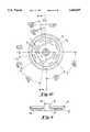
- FIGS. 7 and 8are top plan and bottom plan perspective views of a first encoder wheel of FIG. 1;
- FIG. 9is a top plan view of the first encoder wheel of FIG. 7;
- FIG. 10is a bottom plan view of the first encoder wheel of FIG. 8;
- FIG. 11is a sectional elevational view of the first encoder wheel of FIG. 10 taken along the line A--A;
- FIGS. 12 and 13are top plan and bottom plan perspective views of a second encoder wheel of FIG. 1;
- FIG. 14is a top plan view of the second encoder wheel of FIG. 12;
- FIG. 15is a bottom plan view of the second encoder wheel of FIG. 13;
- FIG. 16is a sectional elevational view of the second encoder wheel of FIG. 15 taken along the line A--A;
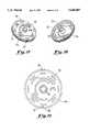
- FIGS. 17 and 18are top plan and bottom plan perspective views of a third encoder wheel of FIG. 1;
- FIG. 19is a top plan view of the third encoder wheel of FIG. 17;
- FIG. 20is a bottom plan view of the third encoder wheel of FIG. 18;
- FIG. 21is a sectional elevational view of the third encoder wheel of FIG. 20 taken along the line A--A;
- FIGS. 22 and 23are top plan and bottom plan perspective views of a fourth encoder wheel of FIG. 1;
- FIG. 24is a top plan view of the fourth encoder wheel of FIG. 22;
- FIG. 25is a bottom plan view of the fourth encoder wheel of FIG. 23;
- FIG. 26is a sectional elevational view of the fourth encoder wheel of FIG. 25 taken along the line A--A;
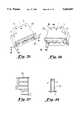
- FIGS. 27 and 28are top plan and bottom plan perspective views of a pinion of FIG. 1;
- FIG. 29is a top plan view of the pinion of FIG. 27;
- FIG. 30is an elevational view of the pinion of FIG. 29;
- FIGS. 31 and 32are top plan and bottom plan perspective views of a bottom tower of a tower assembly of FIG. 1;
- FIG. 33is a sectional top plan view of the bottom tower of FIG. 31 taken along the line A--A;
- FIG. 34is a side sectional view of the bottom tower of FIG. 32 taken along the line B--B;
- FIGS. 35 and 36are top plan and bottom plan perspective views of a middle tower of a tower assembly of FIG. 1;
- FIG. 37is a sectional top plan view of the middle tower of FIG. 35 taken along the line A--A;
- FIG. 38is a side sectional view of the middle tower of FIG. 36 taken along the line B--B;
- FIGS. 39 and 40are top plan and bottom plan perspective views of a top tower of a tower assembly of FIG. 1;
- FIG. 41is a sectional top plan view of the top tower of FIG. 39 taken along the line A--A;
- FIG. 42is a side sectional view of the top tower of FIG. 40 taken along the line B--B;
- FIG. 43is a partly schematic partly block diagram illustrating the processing electronics of a sensor of FIG. 1.
- FIG. 1an exploded perspective view of an absolute encoder 10 according with an embodiment of the present invention.
- the principal components of the absolute encoder 10are a sensing means which is identified by the numeral 12 and an encoder wheel assembly 13, with each of these components being provided within a housing 16.
- the encoder wheel assembly 13in accordance with the present invention comprises a plurality of encoder wheels, which in the present embodiment a total of four encoder wheels are provided, and these are identified in FIG. 1 by the numbers 14a-d.
- the first and third encoder wheels 14a and c, respectively,are mounted on a first shaft 18 and the second and fourth encoder wheels 14b and d, respectively, are mounted on a second shaft 20.
- the first shaft 18in turn extends out through an opening 22 through the housing 16 which is connected with an input gear 24.
- the first and second shafts 18 and 20are comprised of stainless steel.
- the input gear 24as best seen in FIGS. 3-6, is a substantially circular shaped disk member preferably molded of plastic, such as Hoechst Celanese resin, celron M270, and includes a plurality of spaced teeth on its peripheral surface.
- the input gear 24also includes an aperture 25 which is generally in the shape of a "D" which receives a corresponding D-shaped portion of the first shaft 18 for connection.
- the input gear 24is provided in connection with a drive shaft, which includes proximate its upper end a plurality of teeth on its peripheral surface for engaging the teeth of the input gear 24.
- the drive shaftis in turn connected with or made a part of a rotary member (not shown) which is to be monitored by the absolute encoder 10.
- a rotary memberwhich is to be monitored with respect to its angular position, for example, an output shaft of a rotary actuator such as a valve actuator.
- a rotary actuatorsuch as a valve actuator.
- eachare substantially circular shaped disk members which are preferably injection molded of thermoplastic or thermosetting materials, such as Hoechst Celanese resin, celcon M270, however, other manufacturing techniques and other materials can also be utilized for the same purpose.
- each of the encoder wheels 14a-14dare provided with at least one code sequence extending concentrically around the encoder wheel.
- each encoder wheel 14a-14dincludes a series of four code sequences around the encoder wheel.
- the four code sequences in relation to the four encoder wheels 14a-dare identified by the letters a-d in FIGS. 10, 15, 20 and 25. The function and operation of the code sequences will be described in more detail below.
- the first encoder wheel 14aincludes on its circumferential surface an upper flange 28 and a lower flange 30, with the lower flange 30 extending generally radially outward and the upper flange surface 28 extending generally perpendicularly upward proximate the lower flange 30.
- the upper flange surface 28includes extending generally radially outward therefrom four pairs of teeth 32 at spaced separation. In the present embodiment, each of the four pairs of teeth 32 are spaced at 90° intervals around the circumference of the wheel 14a. Further, the two teeth which comprise the four pairs 32 are positioned adjacent the other as best shown in FIG. 9.
- first encoder wheel 14ais included with a cavity within its upper surface and a substantially annular ring member 36 is provided which extends outwardly from the upper surface proximate the center of the encoder wheel 14a.
- a second substantially annular ring member 38extends from the bottom surface, although a distance less than that associated with the annular ring member 36.
- a substantially cylindrical cavity defining a timing mark 33is also included within the upper flange 28 proximate and between one of the four pairs of teeth 32.
- the first encoder wheel 14ais mounted to the first shaft 18 and for this purpose an aperture 40 is formed extending through the first encoder wheel 14a through each of the annular ring members 36 and 38.
- the first encoder wheel 14ais adapted to be rotatable with the first shaft 18, and for this purpose in this embodiment the aperture 40 extending through the first encoder wheel 14a is generally in the shape of a "D" which receives the correspondingly D-shaped portion of the first shaft 18. In this manner, the first encoder wheel 14a will be fixed for rotation with the first shaft 18.
- the second encoder wheel 14b as shown in FIGS. 12-16 similar to the first encoder wheel 14aalso includes two flanges extending around the periphery of the wheel which are identified by the numerals 44 and 46.
- the top flange 44is also included with a pair of teeth extending radially from its outer surface which is shown at 45. In this embodiment, two pairs of teeth 45 are shown which are spaced at 180° intervals.
- the lower flange 46includes a plurality of teeth 47 at its outer surface which extend around the circumference of the encoder wheel 14b. Generally, the spacing between each of the individual teeth 47 on the lower flange 46 is the same as that between the two teeth comprising the pair 45.
- a substantially cylindrical aperture 49 defining a timing markis provided within the top flange 44 of the second encoder wheel 14b proximate and between one of the two pairs of teeth 45.
- a cavityis included within the upper surface of the second encoder wheel 14b and two substantially annular ring members 48 and 50 are also provided extending outward from the upper and bottom surfaces, respectively, similar to that shown in relation to the first encoder wheel 14a.
- the second encoder wheel 14bis included with an aperture 52 extending therethrough, which is substantially cylindrical in configuration and this receives a substantially cylindrical portion of the second shaft 20. This relationship between the substantially cylindrical aperture 52 and second shaft 20 is such that the rotation of the second encoder wheel 14b is independent of the second shaft 20.
- the third encoder wheel 14c as illustrated in FIGS. 17-21 similar to the first two encoder wheelsalso includes upper and lower flanges around the circumference identified by 56 and 58. Similar to the second encoder wheel 14b, the upper flange 56 includes two pairs of teeth 60 spaced at 180° apart. In addition, a substantially cylindrical aperture 61 defining a timing mark 61 is provided proximate and between one of the two pairs of teeth 60 within the upper flange 56 of the third encoder wheel 14c. Further, the lower flange 58 is provided with a plurality of spaced teeth 63 surrounding the periphery thereof. Also, two substantially annular ring members 62 and 64 are shown extending proximate the center from the upper and lower surfaces of the third encoder wheel 14c, respectively.
- annular ring member 64extends outward from the lower surface of the third encoder wheel 14c a distance which is greater than that of the annular ring member 62.
- a substantially cylindrical aperture 66is provided through each annular ring member 62 and 64 through the third encoder wheel 14c. Also, the substantially cylindrical aperture 66 is received onto a substantially cylindrical portion of the first shaft 18, and this configuration provides that the rotation of the third encoder wheel 14c is independent of the first shaft 18, similar to that with relation to the second encoder wheel 14b on the second shaft 20.
- the lower surface of the encoder wheel 14cis provided with a cavity therein and the upper surface is substantial planar.
- the fourth encoder wheel as shown in FIGS. 22-26is identified by the numeral 14d and is different from that shown in relation to the first three encoder wheels since two separate flanges are not provided. Rather, as best shown in the FIGS. 22 and 23, the radius of the fourth encoder wheel 14d is substantially constant around the circumference thereof. Also, similar to the third encoder wheel 14c, the upper surface is substantially planar and a cavity is provided within the bottom surface. Further, similar to the third encoder wheel 14c, the fourth encoder wheel 14d includes upper and lower substantially annular ring members 68 and 70, respectively, with the lower ring member 70 extending outwardly a distance greater than that of the upper annular ring member 68.
- a substantially cylindrical aperture 72extends through each of the annular ring members 68 and 70 through the wheel, and this is engaged by the second shaft 20 in a manner similar to the second and third encoder wheels.
- Another difference in the fourth encoder wheel 14dis that extending outward from the periphery thereof are a plurality of teeth 74 at spaced separation which extend completely around the circumference.
- the spacing between each tooth 74is similar to that in relation to the teeth of the lower flanges 64 and 46 in relation to the third and second encoder wheels, although the width of the teeth 74 of the fourth encoder wheel 14d are greater than the other two wheel members.
- a substantially cylindrical cavity 71 defining a timing markis provided within the upper surface proximate and between two of the plurality of teeth 74 extending around the circumference.
- the housing 16 as illustrated in FIG. 1can be manufactured by conventional techniques, such as injection molding and of conventional materials, such as General Electric resin, xenoy 6620.
- two substantially annular seating members 76 and 78are formed extending from the inner surface of the bottom of the housing 16, which are adapted to receive the second encoder wheel 14b and first encoder wheel 14a, respectively.
- the first annular seating member 76extends outward from the inner surface of the housing 16 a distance greater than that of the annular seating member 78.
- the position of the second encoder wheel 14bis offset relative to the position of the first encoder wheel 14a, which is seated on the annular seating member 78.
- the annular seating member 76also is provided with a substantially cylindrical cavity 80 within its upper surface in order to receive the second shaft 20, which supports the position of the second encoder wheel 14b and fourth encoder wheel 14d in housing 16.
- the first shaft 18extends out through the aperture 22 in the housing 16 and this engages the input gear 24, which supports the position of the first encoder wheel 14a and third encoder wheel 14c in housing 16.
- the fourth encoder wheel 14dis also offset in relation to the third encoder wheel 14c.
- the annular ring member 64 of the third encoder wheel 14cseats against the annular ring member 36 of the first encoder wheel 14a.
- the annular ring member 70 of the fourth encoder wheel 14dis seated against the annular ring member 48 of the second encoder wheel 14b.
- encoder wheels 14b, 14c and 14dare rotatable relative to the rotational movements of the input gear 24 through its connection with the drive shaft, which causes corresponding rotatable movement of the first encoder wheel 14a.
- the pinion 82is positioned between the first encoder wheel 14a and the second encoder wheel 14b
- the second pinion 84is positioned between the second encoder wheel 14b and the third encoder wheel 14c
- the third pinion 86is positioned between the third encoder wheel 14c and the fourth encoder wheel 14d.
- This particular position of the three pinions 82, 84 and 86is supported by a pinion shaft 88 which is positioned within the housing 16.
- eachare preferably injected molded of thermoplastic or thermosetting materials, for examples, Hoechst Celanese resin, celcon M270, however other techniques or materials could be used.
- the pinion shaft 88is preferably comprised of stainless steel.
- annular seating member 90is also provided within the inner surface of the bottom of the housing 16 which works to seat the first pinion 82 in an offset position. Further, the annular seating member 90 is also included with a substantially cylindrical cavity 92 within its upper surface for receiving the shaft 88. As to the configuration of the pinions 82, 84 and 86, each are the same, and for illustration purposes the portions are described in relation to the pinion 82 shown in FIGS. 27-30. Pinion 82 as shown is a generally elongated member which includes a series of long teeth 94 and short teeth 96 extending circumferentially around the outer surface.
- the position of the long teeth 94 and short teeth 96are alternating, with there being four long teeth 94 spaced at 90° intervals and four short teeth 96 also spaced at 90° intervals, which results with a spacing of 45° between each respective long tooth 94 and short tooth 96.
- a substantially cylindrical aperture 98is provided extending through the pinion 82 which connects with the pinion shaft 88 for rotatable movement.
- the rotation of each of the pinions 82, 84 and 86are independent of one another on the shaft. In particular, on assembly, as best shown in FIGS.
- the first pinion 82is positioned so that the short teeth 96 are adjacent the upper flange 28 of the first encoder wheel 14a and will engage the pairs of teeth 32 upon rotation of the first encoder wheel 14a.
- the long teeth 94 of the first pinion 82are positioned to be engaged with the teeth 47 of the lower flange 46 of the second encoder wheel 14b.
- the second pinion 84is positioned so that the short teeth are adjacent the upper flange 44 of the second encoder wheel 14b for engagement by the pair of teeth 45 upon rotation, and the long teeth are in engagement with the teeth 63 of the lower flange 58 of the third encoder wheel 14c.
- the third pinion 86is positioned with its short teeth in engagement with the upper flange 56 of the third encoder wheel 14c for engagement by the pairs of teeth 60 upon rotation, and the long teeth are in engagement with the teeth 74 of the fourth encoder wheel 14d.
- the operation of the encoder wheel assembly 13 defined by the four encoder wheels and the three pinionswill be described in more detail hereafter.
- each of the four encoder wheels in this embodimentincludes a series of four code sequences extending concentrically around each wheel.
- these code sequencesprovide the information which is evaluated to determine the shaft position.
- defined regions of each code sequenceare evaluated which provides the necessary information as to the relative position of the shaft.
- the sensing means 12is provided which monitors the defined regions of each of the respective code sequences as will be described below.
- the code sequencesare formed of slots of various lengths and provided at various spaced intervals which extend through the encoder wheels. The sensing means 12 operates by monitoring the defined region of each of the four code sequences on each of the encoder wheels, which is a total of 16 different defined regions.
- the present inventionevaluates the rotary position by monitoring any of the changes in the information detected at each of the defined regions.
- the data monitored by the sensing means 12 corresponding to each defined regionis represented by one bit, with the total number of bits from the four encoder wheels comprising a 16 bit integer value.
- the code sequencesare arranged so that the digital representation of the rotary position corresponds to grey code in that only one bit of the 16 bit integer value changes corresponding to each incremental change in rotary position.
- the sensing means 12since only one bit of the integer value changes, there is no need for the sensing means 12 to monitor more than one bit change of information at a time, and accordingly process that information. Further, the detection of rotary position is independent of the direction of rotation of the rotary member and a single bit change will correspond with either clockwise or counterclockwise rotation of the encoder 10.
- the sensing means 12 of the present inventionis specifically adapted to monitor all of the code sequences which will determine the corresponding 16 bit integer value associated with the rotary position. Thereafter, every incremental change in rotary position will correspond with a one bit change in the 16 bit integer value and this will in turn be monitored by the sensing means 12.
- FIGS. 10, 15, 20 and 25best illustrate the relationship between each of the respective slots in the four encoder wheels which provide the grey code representation of rotary position.
- the first encoder wheel 14aincludes a configuration in which the same pattern of slots is provided twice over the wheel, and with the second and third encoder wheels 14b and 14c, the patterns associated with each of these are identical to the other.
- the attached figuresillustrate in greater detail the configuration of the slots comprising the code sequences.
- the first encoder wheel 14ais illustrated in FIG. 10.
- the first code sequenceis identified by a and is closest to the center.
- the code sequence aincludes two slots which are each approximately 90° in length and spaced at approximately 90° intervals.
- the second code sequence bincludes four slots which are each approximately 45° in length and spaced at approximately 45° intervals.
- the third code sequence cincludes eight slots which are each approximately 22.5° in length and spaced at approximately 22.5° intervals.
- the fourth code sequence dincludes sixty-four slots which are each approximately 1.875° in length and spaced at approximately 3.75° intervals.
- the second encoder wheel 14bis illustrated in FIG. 15.
- the first code sequence a as shownincludes one slot which is approximately 180° in length.
- the second code sequence bincludes two slots which are each approximately 90° in length and spaced at approximately 90° intervals.
- the third code sequence cincludes four slots which are each approximately 45° in length and spaced at approximately 45° intervals.
- the fourth code sequence dincludes eight slots which are each approximately 22.5° in length and spaced at approximately 22.5° intervals.
- the third encode wheel 14cis shown in FIG. 20. As indicated above, the pattern associated with the code sequences of the third encoder wheel 14c is the same as that of the second encoder wheel 14b.
- the fourth encoder wheel 14dis illustrated in FIG. 25.
- the first code sequence aincludes two slots which are each approximately 90° in length and spaced at approximately 90° intervals.
- the second code sequence balso includes two slots which are each approximately 90° in length and spaced at approximately 90° intervals.
- the third code sequence cincludes four slots which are each approximately 45° in length and spaced at approximately 45° intervals.
- the fourth code sequence dincludes eight slots which are each approximately 22.5° in length and spaced at approximately 22.5° intervals.
- the sensing means 12provides light illuminated by a light emitting means on one side of the wheel proximate the defined region which is detected by a detector means provided proximate the opposite side of the wheel.
- a detector meansprovided proximate the opposite side of the wheel.
- light illuminated from the light emitting meansis identified by the detector means when the encoder wheel is positioned so that a slot is within the defined region. Otherwise, none of the illuminated light will be able to reach the detector means.
- the detection of lightis represented by a "1" and when no light is detected this is represented by a "0".
- each tower memberis a generally rectangular member preferably injection molded of thermoplastic or thermosetting materials, such as General Electric resin cycoloy MC1300, and preferably is to be coated with a reflective covering such as bright nickel plating, and includes substantially planar upper and bottom surfaces and also side portions which connect the upper and bottom surfaces.
- the tower membersare configured in two columns of three towers and connected with the circuit board 104.
- the bottom tower in each columnincludes four apertures only within its upper surface, as illustrated in FIGS. 31-34 at 120, the middle towers in each column including four apertures in both the upper and bottom surfaces, as illustrated in FIGS. 35-38 at 122, and the top towers including four apertures only within its bottom surfaces, as illustrated in FIGS. 39-42 at 124.
- This particular configuration of aperturesallows light illuminated from the LEDs to pass out from the towers onto the defined regions of the code sequences, and when a slot is positioned on a defined region, the light is passed through the slot and through the adjacent tower aperture to the photo transistor.
- the bottom towers 120include LEDs or photo transistors proximate the apertures in the upper surfaces
- the middle towers 122include photo transistors or LEDs proximate the apertures in the lower surfaces and the upper surfaces
- the top towers 124include photo transistors or LEDs proximate the apertures in the lower surfaces.
- each tapered portionis included with a reflective type of material on its surface in order to reflect the passage of light both out of and into the apertures relative to the LEDs and the phototransistors.
- the tapered portions in the present embodimentare coated with the reflective material, for example electroless nickel plated.
- the annular bosses extending from the baseare connected with the circuit board 104. In this embodiment, two of the opposing bosses 126 are generally longer and are adapted for heat staking relative to the circuit board 104.
- thiscontains the electronic circuitry, including the photo transistors and the LEDs of the sensing means 12.
- the arrangement of the photo transistors and LEDsare illustrated extending from the board 104 in FIG. 1, which are received within the cylindrical cavities within the base portion of each tower member as illustrated in FIG. 2c.
- each encoder wheelis positioned between two tower members and the apertures through each tower member are positioned adjacent a separate code sequence.
- the second encoder wheel 14bis positioned between the bottom and middle towers 120 and 122, respectively, of the second column
- the fourth encoder wheel 14dis positioned between the middle and upper towers 122 and 124, respectively, of the second column.
- the first encoder wheel 14ais positioned between the bottom and middle towers 120, 122 of the first column
- the third encoder wheel 14cis positioned between the middle and upper towers 122, 124 of the first column.
- FIGS. 32, 35, 36 and 39the position of the four apertures in each tower are identified by the letters a-d.
- the aperture dis closest to the base
- aperture bis further from the base than d
- aperture cis further from the base than b
- aperture ais the furthest from the base.
- the tower apertures aare provided proximate the code sequences a
- the tower apertures care provided proximate the code sequences c
- the tower apertures bare provided proximate the code sequences b
- the tower apertures dare provided proximate the code sequences d.
- the arrangement of the four encoder wheelsprovide an intermittent style gearing arrangement.
- the connection between the input gear 24 and drive shaftprovide rotation of the four encoder wheels 14a-d.
- each incremental change in rotary position of the rotary membercorresponds with rotation of the input gear 24 by one tooth, which preferably corresponds to one bit through its connection with the drive shaft.
- each incremental change in rotary positioncorresponds to a single bit change in the 16 bit integer value.
- the rotation of the input gear 24provides a corresponding amount of rotation of the first encoder wheel 14a by the first shaft 18.
- each 90° rotation of the first encoder wheel 14acorresponds with the rotation of the second encoder wheel 14b by one bit through the engagement of the first encoder wheel teeth 32 and the second encoder wheel teeth 47 with the teeth of the first pinion 82.
- each 180° rotation of the second encoder wheel 14bcorresponds with rotation of the third encoder wheel 14c by one bit through the engagement of the second encoder wheel teeth 45 with the third encoder wheel teeth 63 with the second pinion 84.
- each 180° rotation of the third encoder wheel 14ccorresponds with rotation of the fourth encoder wheel 14d by one bit through engagement of the third encoder wheel teeth 60 and the fourth encoder wheel teeth 74 with the third pinion 86.
- the sensing means 12operates by monitoring the position of the encoder wheels via the LEDs and photo transistors.
- the sensing means 12comprises a cmos logic interface which also controls the manner of monitoring of the LEDs and photo transistors during operation of the device.
- the sequence of sensingas indicated earlier the four encoder wheels provide this information as a sixteen bit integer value and preferably is in grey code. Accordingly, the important aspect here is that each bit which is sensed on the four encoder wheels by the sensing means 12 must maintain a constant position relative to the sixteen bit integer value.
- the outermost positioned code sequence d in the second encoder wheel 14bcorrespond to the fifth bit of the sixteen bit integer value.
- the order of the sixteen bit integer valuepreferably begins with the first encoder wheel 14a, with the outermost code sequence d corresponding to the first bit, and ends with the innermost code sequence a of the fourth encoder wheel 14d which comprises the sixteenth bit. It should be understood, however, that any desired order of bit sensing can be utilized for this same purpose.
- FIG. 43is a partly schematic partly block diagram which illustrates an exemplary embodiment of the processing electronics of the sensing means 12 according to the present invention.
- conventional LEDs and photo transistorspreferably infrared emitters and detectors are mounted on a conventional printed wiring board which comprises the circuit board 104.
- a shift register 106for example, a 4-bit universal shift register (75HC195) is included which is provided in connection with the LEDs and the photo transistors by lines 130 and 132, respectively.
- preferably eight LEDs 140 a-hare provided in connection with the shift register 106 as shown which operates to reduce the number of components.
- the number of LEDscan be varied in other applications as well within the spirit of the present invention.
- photo transistors 142 a-pare provided in connection with the shift register 106 in the manner illustrated.
- preferably four LEDsare provided within each of the two middle towers of the tower assembly 102 and four photo transistors are provided within each of the two bottom and top towers of the tower assembly 102. Accordingly, based on this arrangement, in operation of the encoder 10, light is illuminated by the LEDs from the apertures in the upper and bottom surfaces of the middle towers which are detected by the photo transistors through the apertures in the upper and bottom surfaces of the bottom and top towers, respectively.
- This controlis accomplished by utilizing transistors 208 as switches to power pairs of LEDs.
- one each of the LEDs in a particular pairare dedicated to one pair of wheels. Four pairs of LEDs are thus controlled. This configuration ensures that each wheel has a completely determined and controlled LED pattern. As illustrated in FIG.
- the LEDs 140 a, b, c and dare provided within the first middle tower and 140 e, f, g, h are provided within the second middle tower, the photo transistors 142 b, e, g and d are provided within the first bottom tower and 142 a, c, f and h provided within the second bottom tower and the photo transistors 142 n, p, k, i are provided within the first top tower and 142 o, m, l and j provided within the second top tower.
- the LEDs 140a and e and photo transistors b, a, n and Oare provided proximate the tower apertures a; the LEDs 140 b and f and photo transistors e, c, p and provided proximate tower apertures b; the LEDs c and g and photo transistors g, f, k and l provided proximate the tower apertures c; and LEDs d and h and photo transistors d, h, i and j provided proximate tower apertures d.
- the sensing means 12preferably determines which LED pairs are driven and also provides the means for transmitting the photodetectors states to a microprocessor 210 in a usable form.
- the microprocessor 210is located externally to the encoder, and is interfaced through a cable to the encoder.
- the rest modewhich is the most prevalent, is in effect when the encoder wheels are not moving, or moving very slowly which corresponds to when the motor operating the rotary member is not running.
- the position informationis provided at this time.
- additional information about the velocity of the first shaft 18preferably is also gathered.
- the microprocessor 210decides which mode is most appropriate at a given point in time and provides control of the sensing means 12 accordingly.
- a logic 1(high) is serially loaded into the shift register 106.
- the logic 1is controlled by the microprocessor 210 and made available on the j and k (inv) lines 213.
- the microprocessor 210keeps the serial shift line 219 identified as PE high at this time.
- the microprocessor 210toggles the clock line 215 on the shift register 106, the logic 1 is transmitted to the low bit Q 0 and the value of each bit Q 0 to Q 2 prior to the clock edge is moved up to the next highest bit.
- the operation just describedis made more complex by the need to read the state of the detectors.
- the state of the four detectorsis made known to the microprocessor 210 so the position of the wheels can be determined. This is accomplished by bringing the serial shift line 219 low after the logic 1 is made available to the proper output of the shift register 106. When the serial shift line 219 is low, a rising clock edge will allow a parallel load of whatever states are detected on the input bits Q 0 , Q 1 , Q 2 , Q 3 of the shift register 106.
- the states on the input side of the shift register 106will now appear on the output bits P 0 , P 1 , P 2 , P 3 taking the place of the single logic 1 at the shift register 106 output. This is not a problem since the state of the emitters and detectors are no longer being monitored at this point.
- the microprocessor 210monitors the status of the high output bit and immediately sees one state on this clock edge.
- the serial shift line 219is returned high and the detector states, by the latch gate 221, are shifted toward the high bit with rising clock pulses.
- Logic 0is still the input from the microprocessor 210 on the j and k (inv) lines so a set of lows are following the desired data. After three more clock cycles, all the detector states have been read and j and k (inv) lines receive a logic 1 to excite the next emitter pair. This multiplexing process allows the reduced part count of the emitters.
- This processchanges when the motor is running. During this mode, preferably speed is more carefully monitored during motor operation, and the least significant bit is read considerably more often than allowed by the scheme just described.
- the code sequence d in each wheelis the least significant bit, however, as it should be understood, this can be varied.
- the emitter pair relating to the least significant bitis powered continuously and the output of that bit is monitored at all times with a pair of hand gates 200, which are configured as inverters. The outputs of these gates are brought out to the microprocessor 210 over lines 217 for continuous monitoring. Periodically, the position is updated with a read of all devices as in the rest mode. This satisfies the requirement for closer observation during the motor run mode.
- the two modeswork together to provide all the information needed to the microprocessor 210. Also, since the wheel location uniquely describes the position, preferably, a loss of power is followed by a complete read of all devices as in the rest mode. When the read is complete, the position of the member is known.
- the remaining components illustrated in FIG. 43are familiar to those of ordinary skill in the art and are thereby not described in detail for the sake of brevity.
- the arrangement of the four encoder wheels and three pinionsprovides an incremental gearing-type of operation which provides improved accuracy; in particular, motion in this configuration cannot stop on the edge of more than one bit. Thus, the error due to transitions is limited to 1/2 of the magnitude of the least significant bit.
- accuracyis further improved since the present invention produces a sixteen bit integer value while also limiting the number of encoder wheels to four. The accuracy is also improved through use of a tower assembly which upon assembly is mounted to be adjacent each code sequence on the four encoder wheels.
- Another advantageis that the code sequences provided by the four encoder wheels pattern a grey-code configuration, and this provides improved accuracy since only one bit of information changes at any one time, with change in magnitude equal to the least significant bit. Furthermore, this particular operation is the same whether rotation of the shaft would be clockwise or counterclockwise.
- Still another advantage of the present inventionis that manufacture and assembly can be accomplished easily and at low cost.
- the present inventionutilizes many conventional, inexpensive components, such as board mounted LEDs and photo transistors, as well as other conventional electronic components.
- the encoder wheels, pinions, tower assembly and housingcan also be manufactured by conventional techniques and materials, such as by injection molding of plastic.
- the present inventionprovides a code sequence which is comprised of a series of slots formed through the wheels.
- another advantageis that the present invention provides an absolute encoder which allows the retention of position data when power is removed; for example, no batteries are required to maintain position information. Further, the position data can be monitored at any time by sensing the position of the code sequences of the encoder wheels.
- each code sequence describedis preferably identified by a series of slots through the four encoder wheels, however the code sequences can also be represented by other means also, such as sections of reflective and non-reflective material either provided on or within the encoder wheels themselves.
- the present invention as described abovepreferably includes a particular arrangement of code sequences which provide a grey code configuration, however other configurations can also be utilized for this same purpose, such as binary code, etc.
- the present inventionis shown comprising four encoder wheels and including four code sequences on each wheel, it should be understood that any number of encoder wheels and any number of code sequences on each individual wheel can also be provided without departing from the spirit of the present invention.
- the tower assembly describedcan also be comprised of any number of tower members for monitoring the encoder wheels.
- the arrangement of each towerit should be understood that other types of shapes or configurations are also possible and also that the arrangement of the diodes and photo detectors can be changed, for example in relation to the diode, the light of a diode can be directed out of either the upper or bottom surfaces of each tower, and the same would apply to the photo detectors. It is understood, therefore, that this invention is not limited to the particular embodiments disclosed, but it is intended to cover all modifications which are within the scope and spirit of the invention as defined by the appended claims.
Landscapes
- Physics & Mathematics (AREA)
- General Physics & Mathematics (AREA)
- Optical Transform (AREA)
- Transmission And Conversion Of Sensor Element Output (AREA)
Abstract
Description
Claims (34)
Priority Applications (10)
| Application Number | Priority Date | Filing Date | Title |
|---|---|---|---|
| US08/493,271US5640007A (en) | 1995-06-21 | 1995-06-21 | Optical encoder comprising a plurality of encoder wheels |
| TW085107000ATW301083B (en) | 1995-06-21 | 1996-06-11 | |
| IN1098CA1996IN189633B (en) | 1995-06-21 | 1996-06-13 | |
| PCT/US1996/010436WO1997001078A1 (en) | 1995-06-21 | 1996-06-14 | Absolute encoder |
| JP9503884AJPH11508365A (en) | 1995-06-21 | 1996-06-14 | Absolute encoder |
| AU62814/96AAU6281496A (en) | 1995-06-21 | 1996-06-14 | Absolute encoder |
| DE69634537TDE69634537T2 (en) | 1995-06-21 | 1996-06-14 | absolute encoder |
| EP96921641AEP0834056B1 (en) | 1995-06-21 | 1996-06-14 | Absolute encoder |
| FR9607698AFR2736150B1 (en) | 1995-06-21 | 1996-06-20 | ABSOLUTE ANGULAR ENCODER |
| JP2004142859AJP2004226423A (en) | 1995-06-21 | 2004-05-12 | Absolute encoder |
Applications Claiming Priority (1)
| Application Number | Priority Date | Filing Date | Title |
|---|---|---|---|
| US08/493,271US5640007A (en) | 1995-06-21 | 1995-06-21 | Optical encoder comprising a plurality of encoder wheels |
Publications (1)
| Publication Number | Publication Date |
|---|---|
| US5640007Atrue US5640007A (en) | 1997-06-17 |
Family
ID=23959560
Family Applications (1)
| Application Number | Title | Priority Date | Filing Date |
|---|---|---|---|
| US08/493,271Expired - LifetimeUS5640007A (en) | 1995-06-21 | 1995-06-21 | Optical encoder comprising a plurality of encoder wheels |
Country Status (9)
| Country | Link |
|---|---|
| US (1) | US5640007A (en) |
| EP (1) | EP0834056B1 (en) |
| JP (2) | JPH11508365A (en) |
| AU (1) | AU6281496A (en) |
| DE (1) | DE69634537T2 (en) |
| FR (1) | FR2736150B1 (en) |
| IN (1) | IN189633B (en) |
| TW (1) | TW301083B (en) |
| WO (1) | WO1997001078A1 (en) |
Cited By (50)
| Publication number | Priority date | Publication date | Assignee | Title |
|---|---|---|---|---|
| US5734474A (en)* | 1995-09-28 | 1998-03-31 | Helmut Hechinger Gmbh & Co. | Device for determining the location of indicators |
| US6130425A (en)* | 1997-02-14 | 2000-10-10 | Alps Electric Co., Ltd. | Rotating detecting device of multi-rotation body |
| US6255644B1 (en)* | 1997-06-23 | 2001-07-03 | Fanuc Ltd. | Optical rotary encoder |
| US6424928B1 (en) | 2000-06-15 | 2002-07-23 | Eim Company, Inc. | Absolute position detector interpreting abnormal states |
| US6454458B1 (en)* | 1999-05-06 | 2002-09-24 | Asulab S.A. | Timepiece including means for indicating the angular position of coaxial analogue display indicators |
| US6465772B1 (en)* | 1997-10-23 | 2002-10-15 | Nsi Corporation | Optical encoder having multiple thumbwheels with integral encoder patterns |
| US6577985B2 (en) | 2000-12-07 | 2003-06-10 | Eim Company, Inc. | Scalable code absolute logic function (SCALF) encoder |
| WO2003071229A3 (en)* | 2002-02-15 | 2003-11-06 | Methode Electronics Inc | Rapid high resolution position sensor for auto steering |
| US20040022134A1 (en)* | 2002-08-02 | 2004-02-05 | Yiu Chih Hao | Position detecting and correcting device for timepiece |
| US20040085860A1 (en)* | 2002-10-31 | 2004-05-06 | Yiu Chih Hao | Position detecting and correcting device for timepiece |
| KR100451107B1 (en)* | 2002-03-13 | 2004-10-06 | 주식회사 협성사 | Absolute Encoder |
| US6807128B2 (en) | 2002-08-02 | 2004-10-19 | Chih Hao Yiu | Position detecting and correcting device for timepiece |
| US20050002278A1 (en)* | 2001-12-17 | 2005-01-06 | Andreas Dittrich | Radio clockwork mechanism having a detector for setting the clock hands |
| US20060092071A1 (en)* | 2004-09-17 | 2006-05-04 | Andermotion Technologies Llc | Low-profile multi-turn encoder systems and methods |
| US20060186852A1 (en)* | 2003-01-29 | 2006-08-24 | Kozo Sasaki | Servo drive and encoder signal processing ic |
| US20070075232A1 (en)* | 2005-10-01 | 2007-04-05 | Joern Ehrenberg | Position-measuring device |
| US20070180714A1 (en)* | 2003-03-13 | 2007-08-09 | Josef Siraky | Device for measuring the position, the path or the rotational angle of an object |
| WO2007123522A1 (en)* | 2006-04-21 | 2007-11-01 | Flowserve Management Company | Rotary encoder with built-in-self-test |
| US20080048653A1 (en)* | 2004-09-02 | 2008-02-28 | Rotork Controls Limited | Multi-Turn Shaft Encoder |
| US20080185505A1 (en)* | 2005-10-13 | 2008-08-07 | Seiichiro Mizuno | Encoder and Light Receiving Device For Encoder |
| RU2341786C2 (en)* | 2006-12-21 | 2008-12-20 | Владимир Александрович Артемьев | Sea water transparency meter |
| US20090025298A1 (en)* | 2005-11-18 | 2009-01-29 | Ray Hawkins | Device for monitoring motion of a movable closure |
| US20090086581A1 (en)* | 2007-09-28 | 2009-04-02 | Casio Computer Co., Ltd. | Hand position detecting device and apparatus including the device |
| US20090086580A1 (en)* | 2007-09-28 | 2009-04-02 | Casio Computer Co., Ltd. | Hand position detecting device and apparatus including the device |
| US20090152452A1 (en)* | 2007-12-18 | 2009-06-18 | Avago Technologies Ecbu Ip (Singapore) Pte. Ltd. | Reflective multi-turn encoder |
| US20090161120A1 (en)* | 2007-12-25 | 2009-06-25 | Casio Computer Co., Ltd. | Hand position detecting device and method |
| US20090296534A1 (en)* | 2008-05-30 | 2009-12-03 | Casio Computer Co., Ltd. | Hand position detecting device |
| US20100006748A1 (en)* | 2006-10-10 | 2010-01-14 | Hamamatsu Photonics K.K. | Encoder and photodetector for encoder |
| US20100012874A1 (en)* | 2006-04-21 | 2010-01-21 | William T Dolenti | Rotary Encoder Frequency Analysis |
| US20100171029A1 (en)* | 2009-01-08 | 2010-07-08 | Avago Technologies Ecbu (Singapore) Pte. Ltd. | Reflective Multi-Turn Encoders with Different Light Sensing Systems |
| US20100188951A1 (en)* | 2007-08-08 | 2010-07-29 | Eliezer Zeichner | Encoding device, system and method |
| US20100219332A1 (en)* | 2007-06-28 | 2010-09-02 | Mingmin Wan | Electronic Code Disk Position Selecting Device |
| CN102003975A (en)* | 2006-04-21 | 2011-04-06 | 芙罗服务管理公司 | Rotary encoder with built-in self-test |
| AU2006315071B2 (en)* | 2005-11-18 | 2011-07-28 | Automatic Technology (Australia) Pty Ltd | Device for monitoring motion of a movable closure |
| US8023364B2 (en) | 2008-05-28 | 2011-09-20 | Casio Computer Co., Ltd. | Hand position detecting device and hand position control method |
| US20120006982A1 (en)* | 2009-04-14 | 2012-01-12 | Mitsubishi Electric Corporation | Rotary encoder and manufacturing method thereof |
| CN102865400A (en)* | 2006-04-21 | 2013-01-09 | 芙罗服务管理公司 | Valve actuator |
| US20130015333A1 (en)* | 2011-07-15 | 2013-01-17 | Sanyo Denki Co., Ltd. | Encoder with gear mechanism and optical encoder device |
| US8704904B2 (en) | 2011-12-23 | 2014-04-22 | H4 Engineering, Inc. | Portable system for high quality video recording |
| US8749634B2 (en) | 2012-03-01 | 2014-06-10 | H4 Engineering, Inc. | Apparatus and method for automatic video recording |
| US8836508B2 (en) | 2012-02-03 | 2014-09-16 | H4 Engineering, Inc. | Apparatus and method for securing a portable electronic device |
| US9007476B2 (en) | 2012-07-06 | 2015-04-14 | H4 Engineering, Inc. | Remotely controlled automatic camera tracking system |
| US20160040988A1 (en)* | 2014-08-07 | 2016-02-11 | Kabushiki Kaisha Topcon | Absolute encoder and surveying device |
| US9310195B2 (en) | 2010-08-24 | 2016-04-12 | Rotork Controls Limited | Apparatus adapted to provide an indication of an angular position of an input member over multiple turns |
| US9313394B2 (en) | 2012-03-02 | 2016-04-12 | H4 Engineering, Inc. | Waterproof electronic device |
| CN106922167A (en)* | 2014-09-15 | 2017-07-04 | 芙罗服务管理公司 | For sensor and associated component, the system and method for valve system |
| US9723192B1 (en) | 2012-03-02 | 2017-08-01 | H4 Engineering, Inc. | Application dependent video recording device architecture |
| CN116337120A (en)* | 2023-03-29 | 2023-06-27 | 东莞市涛涛电子有限公司 | Photoelectric encoder with electronic rotating disc |
| US20230258280A1 (en)* | 2020-06-18 | 2023-08-17 | Cavagna Group S.P.A. | A valve assembly for pressurized containers |
| DE112006004264B4 (en) | 2006-04-21 | 2024-02-08 | Flowserve Management Company | Encoder frequency analysis |
Families Citing this family (7)
| Publication number | Priority date | Publication date | Assignee | Title |
|---|---|---|---|---|
| DE19601676A1 (en)* | 1996-01-18 | 1997-07-24 | Teves Gmbh Alfred | Steering angle sensor with evaluation of the incremental track for absolute value determination |
| EP1111347B1 (en) | 1999-12-15 | 2001-09-05 | Brown & Sharpe Tesa S.A. | Positional encoder |
| JP4088073B2 (en) | 2002-01-11 | 2008-05-21 | 株式会社ミツトヨ | Absolute position measuring device |
| DE502006006009D1 (en) | 2005-12-16 | 2010-03-11 | Siemens Ag | Monitoring device for a drive device |
| US8082673B2 (en)* | 2009-11-06 | 2011-12-27 | Hexagon Metrology Ab | Systems and methods for control and calibration of a CMM |
| KR101452364B1 (en)* | 2014-04-30 | 2014-10-22 | 주식회사 은하 | Optical encoder of electric powered valve actuator |
| CN105277222A (en)* | 2014-06-16 | 2016-01-27 | 上海鼎曦自动化科技有限公司 | High-precision absolute value encoder |
Citations (24)
| Publication number | Priority date | Publication date | Assignee | Title |
|---|---|---|---|---|
| US3808431A (en)* | 1973-04-26 | 1974-04-30 | G Hedrick | Optical encoder |
| US3989943A (en)* | 1975-07-03 | 1976-11-02 | Campbell John E | Angularly adjustable optical switch assembly |
| US4031386A (en)* | 1976-06-15 | 1977-06-21 | Rockwell International Corporation | Optical transducer encoding apparatus |
| US4056850A (en)* | 1976-01-19 | 1977-11-01 | Dynamics Research Corporation | Absolute relative position encoder processor and display |
| US4123750A (en)* | 1973-11-29 | 1978-10-31 | Dynamics Research Corporation | Signal processor for position encoder |
| US4376161A (en)* | 1981-07-27 | 1983-03-08 | Dynamics Research Corporation | Encoder disc and method of manufacture |
| US4377744A (en)* | 1980-07-14 | 1983-03-22 | The United States Of America As Represented By The Secretary Of The Navy | Remote lens focusing system for an aerial camera |
| US4621256A (en)* | 1983-07-15 | 1986-11-04 | Lockheed Missiles & Space Company, Inc. | Apparatus for measuring rate of angular displacement |
| US4631520A (en)* | 1984-06-08 | 1986-12-23 | Dynamics Research Corporation | Position encoder compensation system |
| US4740690A (en)* | 1982-09-02 | 1988-04-26 | Rockwell International Corporation | Absolute combinational encoders coupled through a fixed gear ratio |
| GB2196494A (en)* | 1986-09-03 | 1988-04-27 | Rotork Controls | Valve actuator control mechanism |
| US4819051A (en)* | 1987-06-29 | 1989-04-04 | Honeywell Inc. | Compensated rotary position encoder |
| US4904861A (en)* | 1988-12-27 | 1990-02-27 | Hewlett-Packard Company | Optical encoder using sufficient inactive photodetectors to make leakage current equal throughout |
| US4947166A (en)* | 1988-02-22 | 1990-08-07 | Dynamics Research Corporation | Single track absolute encoder |
| US4952799A (en)* | 1989-03-10 | 1990-08-28 | Hewlett-Packard Company | Reflective shaft angle encoder |
| US4998013A (en)* | 1988-12-27 | 1991-03-05 | Hewlett-Packard Company | Optical encoder with inactive photodetectors |
| US5062214A (en)* | 1986-10-13 | 1991-11-05 | C. E. Johansson Ab | Absolute measurement scale system |
| US5088061A (en)* | 1990-07-24 | 1992-02-11 | Vlsi Technology, Inc. | Routing independent circuit components |
| US5148020A (en)* | 1991-04-17 | 1992-09-15 | Hewlett-Packard Company | Optical encoder with photodetectors of width equal to and one-half of code wheel's window and spoke width |
| US5252824A (en)* | 1991-07-24 | 1993-10-12 | Schlumberger Industries, S.A. | Analog transmitter of position and direction of rotation having a signal amplitude varies on each change of state of sensors |
| US5276722A (en)* | 1991-07-30 | 1994-01-04 | Mitsubishi Denki K.K. | Absolute multi-revolution encoder |
| US5402275A (en)* | 1992-03-09 | 1995-03-28 | Teac Corporation | Method and apparatus for synchronizing recreated DAT frames and time codes |
| US5402365A (en)* | 1992-10-28 | 1995-03-28 | Motorola, Inc. | Differential odometer dynamic calibration method and apparatus therefor |
| US5402445A (en)* | 1992-08-06 | 1995-03-28 | Nec Corporation | Decision feedback equalizer |
Family Cites Families (5)
| Publication number | Priority date | Publication date | Assignee | Title |
|---|---|---|---|---|
| US4137451A (en)* | 1977-12-22 | 1979-01-30 | Westinghouse Electric Corp. | Detecting circuit for a photocell pattern sensing assembly |
| JPS60143715A (en)* | 1983-12-29 | 1985-07-30 | Ando Electric Co Ltd | Position detecting device |
| US4730110A (en)* | 1984-07-27 | 1988-03-08 | Spaulding Instruments | Shaft position encoder |
| DE4111562C2 (en)* | 1991-04-10 | 1994-12-22 | Hohner Elektrotechnik Kg | Angular position sensor |
| DK0660263T3 (en)* | 1993-12-23 | 2000-08-14 | Gas & Wassermesserfab Ag | Method of providing an electrical signal readout from a multi-digit roller counter for use in a volume measure |
- 1995
- 1995-06-21USUS08/493,271patent/US5640007A/ennot_activeExpired - Lifetime
- 1996
- 1996-06-11TWTW085107000Apatent/TW301083B/zhactive
- 1996-06-13ININ1098CA1996patent/IN189633B/enunknown
- 1996-06-14WOPCT/US1996/010436patent/WO1997001078A1/enactiveIP Right Grant
- 1996-06-14EPEP96921641Apatent/EP0834056B1/ennot_activeExpired - Lifetime
- 1996-06-14DEDE69634537Tpatent/DE69634537T2/ennot_activeExpired - Lifetime
- 1996-06-14JPJP9503884Apatent/JPH11508365A/ennot_activeWithdrawn
- 1996-06-14AUAU62814/96Apatent/AU6281496A/ennot_activeAbandoned
- 1996-06-20FRFR9607698Apatent/FR2736150B1/ennot_activeExpired - Lifetime
- 2004
- 2004-05-12JPJP2004142859Apatent/JP2004226423A/enactivePending
Patent Citations (24)
| Publication number | Priority date | Publication date | Assignee | Title |
|---|---|---|---|---|
| US3808431A (en)* | 1973-04-26 | 1974-04-30 | G Hedrick | Optical encoder |
| US4123750A (en)* | 1973-11-29 | 1978-10-31 | Dynamics Research Corporation | Signal processor for position encoder |
| US3989943A (en)* | 1975-07-03 | 1976-11-02 | Campbell John E | Angularly adjustable optical switch assembly |
| US4056850A (en)* | 1976-01-19 | 1977-11-01 | Dynamics Research Corporation | Absolute relative position encoder processor and display |
| US4031386A (en)* | 1976-06-15 | 1977-06-21 | Rockwell International Corporation | Optical transducer encoding apparatus |
| US4377744A (en)* | 1980-07-14 | 1983-03-22 | The United States Of America As Represented By The Secretary Of The Navy | Remote lens focusing system for an aerial camera |
| US4376161A (en)* | 1981-07-27 | 1983-03-08 | Dynamics Research Corporation | Encoder disc and method of manufacture |
| US4740690A (en)* | 1982-09-02 | 1988-04-26 | Rockwell International Corporation | Absolute combinational encoders coupled through a fixed gear ratio |
| US4621256A (en)* | 1983-07-15 | 1986-11-04 | Lockheed Missiles & Space Company, Inc. | Apparatus for measuring rate of angular displacement |
| US4631520A (en)* | 1984-06-08 | 1986-12-23 | Dynamics Research Corporation | Position encoder compensation system |
| GB2196494A (en)* | 1986-09-03 | 1988-04-27 | Rotork Controls | Valve actuator control mechanism |
| US5062214A (en)* | 1986-10-13 | 1991-11-05 | C. E. Johansson Ab | Absolute measurement scale system |
| US4819051A (en)* | 1987-06-29 | 1989-04-04 | Honeywell Inc. | Compensated rotary position encoder |
| US4947166A (en)* | 1988-02-22 | 1990-08-07 | Dynamics Research Corporation | Single track absolute encoder |
| US4904861A (en)* | 1988-12-27 | 1990-02-27 | Hewlett-Packard Company | Optical encoder using sufficient inactive photodetectors to make leakage current equal throughout |
| US4998013A (en)* | 1988-12-27 | 1991-03-05 | Hewlett-Packard Company | Optical encoder with inactive photodetectors |
| US4952799A (en)* | 1989-03-10 | 1990-08-28 | Hewlett-Packard Company | Reflective shaft angle encoder |
| US5088061A (en)* | 1990-07-24 | 1992-02-11 | Vlsi Technology, Inc. | Routing independent circuit components |
| US5148020A (en)* | 1991-04-17 | 1992-09-15 | Hewlett-Packard Company | Optical encoder with photodetectors of width equal to and one-half of code wheel's window and spoke width |
| US5252824A (en)* | 1991-07-24 | 1993-10-12 | Schlumberger Industries, S.A. | Analog transmitter of position and direction of rotation having a signal amplitude varies on each change of state of sensors |
| US5276722A (en)* | 1991-07-30 | 1994-01-04 | Mitsubishi Denki K.K. | Absolute multi-revolution encoder |
| US5402275A (en)* | 1992-03-09 | 1995-03-28 | Teac Corporation | Method and apparatus for synchronizing recreated DAT frames and time codes |
| US5402445A (en)* | 1992-08-06 | 1995-03-28 | Nec Corporation | Decision feedback equalizer |
| US5402365A (en)* | 1992-10-28 | 1995-03-28 | Motorola, Inc. | Differential odometer dynamic calibration method and apparatus therefor |
Cited By (91)
| Publication number | Priority date | Publication date | Assignee | Title |
|---|---|---|---|---|
| US5734474A (en)* | 1995-09-28 | 1998-03-31 | Helmut Hechinger Gmbh & Co. | Device for determining the location of indicators |
| US6130425A (en)* | 1997-02-14 | 2000-10-10 | Alps Electric Co., Ltd. | Rotating detecting device of multi-rotation body |
| US6255644B1 (en)* | 1997-06-23 | 2001-07-03 | Fanuc Ltd. | Optical rotary encoder |
| US6465772B1 (en)* | 1997-10-23 | 2002-10-15 | Nsi Corporation | Optical encoder having multiple thumbwheels with integral encoder patterns |
| US6454458B1 (en)* | 1999-05-06 | 2002-09-24 | Asulab S.A. | Timepiece including means for indicating the angular position of coaxial analogue display indicators |
| US6424928B1 (en) | 2000-06-15 | 2002-07-23 | Eim Company, Inc. | Absolute position detector interpreting abnormal states |
| US6615156B2 (en) | 2000-06-15 | 2003-09-02 | Eim Company, Inc. | Abnormal state absolute position detector generating direct digital output |
| US6577985B2 (en) | 2000-12-07 | 2003-06-10 | Eim Company, Inc. | Scalable code absolute logic function (SCALF) encoder |
| US20050002278A1 (en)* | 2001-12-17 | 2005-01-06 | Andreas Dittrich | Radio clockwork mechanism having a detector for setting the clock hands |
| WO2003071229A3 (en)* | 2002-02-15 | 2003-11-06 | Methode Electronics Inc | Rapid high resolution position sensor for auto steering |
| US6844541B2 (en)* | 2002-02-15 | 2005-01-18 | Methode Electronics, Inc. | Rapid high resolution position sensor for auto steering |
| US6956198B2 (en) | 2002-02-15 | 2005-10-18 | Methode Electronics, Inc. | Rapid high resolution position sensor for auto steering |
| KR100451107B1 (en)* | 2002-03-13 | 2004-10-06 | 주식회사 협성사 | Absolute Encoder |
| US6731571B2 (en) | 2002-08-02 | 2004-05-04 | Chih Hao Yiu | Position detecting and correcting device for timepiece |
| US6807128B2 (en) | 2002-08-02 | 2004-10-19 | Chih Hao Yiu | Position detecting and correcting device for timepiece |
| US20040022134A1 (en)* | 2002-08-02 | 2004-02-05 | Yiu Chih Hao | Position detecting and correcting device for timepiece |
| US20040085860A1 (en)* | 2002-10-31 | 2004-05-06 | Yiu Chih Hao | Position detecting and correcting device for timepiece |
| US20060186852A1 (en)* | 2003-01-29 | 2006-08-24 | Kozo Sasaki | Servo drive and encoder signal processing ic |
| US7224139B2 (en)* | 2003-01-29 | 2007-05-29 | Harmonic Drive Systems Inc. | Servo driver and encoder signal processing IC |
| US20070180714A1 (en)* | 2003-03-13 | 2007-08-09 | Josef Siraky | Device for measuring the position, the path or the rotational angle of an object |
| US7406772B2 (en)* | 2003-03-13 | 2008-08-05 | Stegmann Gmbh & Co. Kg | Device for measuring the position, the path or the rotational angle of an object |
| US20080048653A1 (en)* | 2004-09-02 | 2008-02-28 | Rotork Controls Limited | Multi-Turn Shaft Encoder |
| US7259695B2 (en) | 2004-09-17 | 2007-08-21 | Andermotion Technologies Llc | Low-profile multi-turn encoder systems and methods |
| US20060092071A1 (en)* | 2004-09-17 | 2006-05-04 | Andermotion Technologies Llc | Low-profile multi-turn encoder systems and methods |
| US8618466B2 (en)* | 2005-10-01 | 2013-12-31 | Dr. Johannes Heidenhain Gmbh | Position-measuring device having a first measuring standard and at least two multiturn code disks |
| US20070075232A1 (en)* | 2005-10-01 | 2007-04-05 | Joern Ehrenberg | Position-measuring device |
| US20080185505A1 (en)* | 2005-10-13 | 2008-08-07 | Seiichiro Mizuno | Encoder and Light Receiving Device For Encoder |
| US8044340B2 (en) | 2005-10-13 | 2011-10-25 | Hamamatsu Photonics K.K. | Encoder and light receiving device for encoder |
| US8037922B2 (en)* | 2005-11-18 | 2011-10-18 | Automatic Technology (Australia) Pty Ltd | Device for monitoring motion of a movable closure |
| US20090025298A1 (en)* | 2005-11-18 | 2009-01-29 | Ray Hawkins | Device for monitoring motion of a movable closure |
| AU2006315071B2 (en)* | 2005-11-18 | 2011-07-28 | Automatic Technology (Australia) Pty Ltd | Device for monitoring motion of a movable closure |
| CN102003975A (en)* | 2006-04-21 | 2011-04-06 | 芙罗服务管理公司 | Rotary encoder with built-in self-test |
| US9086335B2 (en) | 2006-04-21 | 2015-07-21 | Flowserve Management Company | Rotary encoder frequency analysis |
| DE112006004264B4 (en) | 2006-04-21 | 2024-02-08 | Flowserve Management Company | Encoder frequency analysis |
| DE112006003859B4 (en)* | 2006-04-21 | 2021-04-01 | Flowserve Management Co. | Rotary encoder frequency analysis |
| US20100001177A1 (en)* | 2006-04-21 | 2010-01-07 | Dolenti William T | Rotary Encoder with Built-in-Self-Test |
| GB2479089B (en)* | 2006-04-21 | 2011-11-23 | Flowserve Man Co | Rotary encoder with built-in-self-test |
| US20100012874A1 (en)* | 2006-04-21 | 2010-01-21 | William T Dolenti | Rotary Encoder Frequency Analysis |
| GB2479089A (en)* | 2006-04-21 | 2011-09-28 | Flowserve Man Co | Rotary encoder for position sensing and fault diagnosis in valve actuators |
| GB2450663B (en)* | 2006-04-21 | 2011-11-16 | Flowserve Man Co | Rotary encoder with built-in-self-test |
| GB2450663A (en)* | 2006-04-21 | 2008-12-31 | Flowserve Man Co | Rotary encoder with built-in-self-test |
| CN102865400B (en)* | 2006-04-21 | 2014-11-12 | 芙罗服务管理公司 | Valve actuator |
| CN101473185B (en)* | 2006-04-21 | 2011-03-16 | 芙罗服务管理公司 | Rotary encoder with built-in self-test |
| WO2007123522A1 (en)* | 2006-04-21 | 2007-11-01 | Flowserve Management Company | Rotary encoder with built-in-self-test |
| CN102003975B (en)* | 2006-04-21 | 2013-12-25 | 芙罗服务管理公司 | Rotary encoder with built-in self-test |
| US8471194B2 (en) | 2006-04-21 | 2013-06-25 | Flowserve Management Company | Rotary encoder for diagnosing problems with rotary equipment |
| CN102865400A (en)* | 2006-04-21 | 2013-01-09 | 芙罗服务管理公司 | Valve actuator |
| US20100006748A1 (en)* | 2006-10-10 | 2010-01-14 | Hamamatsu Photonics K.K. | Encoder and photodetector for encoder |
| RU2341786C2 (en)* | 2006-12-21 | 2008-12-20 | Владимир Александрович Артемьев | Sea water transparency meter |
| US20100219332A1 (en)* | 2007-06-28 | 2010-09-02 | Mingmin Wan | Electronic Code Disk Position Selecting Device |
| US20100188951A1 (en)* | 2007-08-08 | 2010-07-29 | Eliezer Zeichner | Encoding device, system and method |
| US8023362B2 (en)* | 2007-09-28 | 2011-09-20 | Casio Computer Co., Ltd. | Hand position detecting device and apparatus including the device |
| US7859952B2 (en)* | 2007-09-28 | 2010-12-28 | Casio Computer Co., Ltd. | Hand position detecting device and apparatus including the device |
| US20090086580A1 (en)* | 2007-09-28 | 2009-04-02 | Casio Computer Co., Ltd. | Hand position detecting device and apparatus including the device |
| US20090086581A1 (en)* | 2007-09-28 | 2009-04-02 | Casio Computer Co., Ltd. | Hand position detecting device and apparatus including the device |
| US20090152452A1 (en)* | 2007-12-18 | 2009-06-18 | Avago Technologies Ecbu Ip (Singapore) Pte. Ltd. | Reflective multi-turn encoder |
| US8107324B2 (en) | 2007-12-25 | 2012-01-31 | Casio Computer Co., Ltd. | Hand position detecting device and method |
| US20090161120A1 (en)* | 2007-12-25 | 2009-06-25 | Casio Computer Co., Ltd. | Hand position detecting device and method |
| US8023364B2 (en) | 2008-05-28 | 2011-09-20 | Casio Computer Co., Ltd. | Hand position detecting device and hand position control method |
| US8208348B2 (en) | 2008-05-30 | 2012-06-26 | Casio Computer Co., Ltd. | Hand position detecting device |
| US20090296534A1 (en)* | 2008-05-30 | 2009-12-03 | Casio Computer Co., Ltd. | Hand position detecting device |
| US20100171029A1 (en)* | 2009-01-08 | 2010-07-08 | Avago Technologies Ecbu (Singapore) Pte. Ltd. | Reflective Multi-Turn Encoders with Different Light Sensing Systems |
| US8063355B2 (en)* | 2009-01-08 | 2011-11-22 | Avago Technologies Limited | Reflective multi-turn encoders with different light sensing systems |
| US8704157B2 (en)* | 2009-04-14 | 2014-04-22 | Mitsubishi Electric Corporation | Optical rotary encoder and manufacturing method thereof |
| US20120006982A1 (en)* | 2009-04-14 | 2012-01-12 | Mitsubishi Electric Corporation | Rotary encoder and manufacturing method thereof |
| US9310195B2 (en) | 2010-08-24 | 2016-04-12 | Rotork Controls Limited | Apparatus adapted to provide an indication of an angular position of an input member over multiple turns |
| US20130015333A1 (en)* | 2011-07-15 | 2013-01-17 | Sanyo Denki Co., Ltd. | Encoder with gear mechanism and optical encoder device |
| US8878125B2 (en)* | 2011-07-15 | 2014-11-04 | Sanyo Denki Co., Ltd. | Encoder with gear mechanism and optical encoder device |
| US9253376B2 (en) | 2011-12-23 | 2016-02-02 | H4 Engineering, Inc. | Portable video recording system with automatic camera orienting and velocity regulation of the orienting for recording high quality video of a freely moving subject |
| US8704904B2 (en) | 2011-12-23 | 2014-04-22 | H4 Engineering, Inc. | Portable system for high quality video recording |
| US9160899B1 (en) | 2011-12-23 | 2015-10-13 | H4 Engineering, Inc. | Feedback and manual remote control system and method for automatic video recording |
| US8836508B2 (en) | 2012-02-03 | 2014-09-16 | H4 Engineering, Inc. | Apparatus and method for securing a portable electronic device |
| US8749634B2 (en) | 2012-03-01 | 2014-06-10 | H4 Engineering, Inc. | Apparatus and method for automatic video recording |
| US9565349B2 (en) | 2012-03-01 | 2017-02-07 | H4 Engineering, Inc. | Apparatus and method for automatic video recording |
| US9800769B2 (en) | 2012-03-01 | 2017-10-24 | H4 Engineering, Inc. | Apparatus and method for automatic video recording |
| US9313394B2 (en) | 2012-03-02 | 2016-04-12 | H4 Engineering, Inc. | Waterproof electronic device |
| US9723192B1 (en) | 2012-03-02 | 2017-08-01 | H4 Engineering, Inc. | Application dependent video recording device architecture |
| US9294669B2 (en) | 2012-07-06 | 2016-03-22 | H4 Engineering, Inc. | Remotely controlled automatic camera tracking system |
| US9007476B2 (en) | 2012-07-06 | 2015-04-14 | H4 Engineering, Inc. | Remotely controlled automatic camera tracking system |
| US20160040988A1 (en)* | 2014-08-07 | 2016-02-11 | Kabushiki Kaisha Topcon | Absolute encoder and surveying device |
| US9891046B2 (en)* | 2014-08-07 | 2018-02-13 | Kabushiki Kaisha Topcon | Absolute rotary encoder for surveying device |
| AU2014406529B2 (en)* | 2014-09-15 | 2019-10-31 | Flowserve Pte. Ltd. | Sensors for valve systems and related assemblies, systems and methods |
| CN106922167B (en)* | 2014-09-15 | 2019-11-19 | 芙罗服务管理公司 | Sensors for valve systems and related assemblies, systems and methods |
| AU2019257358B2 (en)* | 2014-09-15 | 2020-12-24 | Flowserve Pte. Ltd. | Sensors for valve systems and related assemblies, systems and methods |
| US20170292628A1 (en)* | 2014-09-15 | 2017-10-12 | Flowserve Management Company | Sensors for valve systems and related assemblies, systems and methods |
| US11054057B2 (en)* | 2014-09-15 | 2021-07-06 | Flowserve Management Company | Sensors for valve systems and related assemblies, systems and methods |
| CN106922167A (en)* | 2014-09-15 | 2017-07-04 | 芙罗服务管理公司 | For sensor and associated component, the system and method for valve system |
| US20230258280A1 (en)* | 2020-06-18 | 2023-08-17 | Cavagna Group S.P.A. | A valve assembly for pressurized containers |
| US12146586B2 (en)* | 2020-06-18 | 2024-11-19 | Cavagna Group S.P.A. | Valve assembly for pressurized containers |
| CN116337120A (en)* | 2023-03-29 | 2023-06-27 | 东莞市涛涛电子有限公司 | Photoelectric encoder with electronic rotating disc |
| CN116337120B (en)* | 2023-03-29 | 2024-02-13 | 东莞市涛涛电子有限公司 | Photoelectric encoder with electronic rotating disc |
Also Published As
| Publication number | Publication date |
|---|---|
| FR2736150B1 (en) | 2001-03-09 |
| DE69634537T2 (en) | 2006-03-30 |
| EP0834056A1 (en) | 1998-04-08 |
| DE69634537D1 (en) | 2005-05-04 |
| TW301083B (en) | 1997-03-21 |
| JP2004226423A (en) | 2004-08-12 |
| WO1997001078A1 (en) | 1997-01-09 |
| FR2736150A1 (en) | 1997-01-03 |
| EP0834056A4 (en) | 1999-11-24 |
| EP0834056B1 (en) | 2005-03-30 |
| IN189633B (en) | 2003-04-05 |
| AU6281496A (en) | 1997-01-22 |
| JPH11508365A (en) | 1999-07-21 |
Similar Documents
| Publication | Publication Date | Title |
|---|---|---|
| US5640007A (en) | Optical encoder comprising a plurality of encoder wheels | |
| ES2112219T3 (en) | System to determine the position of an engine in a biomedical device | |
| US5565861A (en) | Multidigit counting wheel mechanism for a volume-measuring instrument | |
| US4086488A (en) | Digital pressure gauge system | |
| US6848187B2 (en) | Rotation angle detector | |
| US4947166A (en) | Single track absolute encoder | |
| US6305234B1 (en) | Absolute encoder | |
| US6424928B1 (en) | Absolute position detector interpreting abnormal states | |
| US4965446A (en) | Optical interrupter system with vibration compensation | |
| US5608394A (en) | Position detecting method and apparatus | |
| US5029304A (en) | Sensor with absolute digital output utilizing Hall Effect devices | |
| US4833316A (en) | Rotary encoder | |
| EP3783318B1 (en) | Position determination for valves | |
| MXPA01000833A (en) | Angle encoder. | |
| JPS6236518A (en) | Positional encoder | |
| KR20050002825A (en) | Rapid high resolution position sensor for auto steering | |
| EP0509828A2 (en) | Optical encoder with improved indux pulse | |
| US5274229A (en) | Absolute position encoder | |
| CN106763719B (en) | A kind of rotation gearshift | |
| SE436388B (en) | VIEW TO READ SCREWS ON MULTI-SCALE Coding Devices, And A Multivariate ABSOLUTE ANGLE Coding Device | |
| US10921163B2 (en) | Optical encoder with incremental and absolute code sensors and defining distance between geometric centers of adjacent photosensors of an incremental code sensor | |
| US4634859A (en) | Optical encoder with two photosensors | |
| US4555625A (en) | Precision drum encoder | |
| KR100451107B1 (en) | Absolute Encoder | |
| KR200245410Y1 (en) | Gear Box for Robot |
Legal Events
| Date | Code | Title | Description |
|---|---|---|---|
| AS | Assignment | Owner name:LIMITORQUE CORPORATION, VIRGINIA Free format text:ASSIGNMENT OF ASSIGNORS INTEREST;ASSIGNORS:TALBOTT, KENNETH R.;HYLTON, CHARLES L.;AUSTIN, JAMES A.;AND OTHERS;REEL/FRAME:007572/0868 Effective date:19950620 | |
| STCF | Information on status: patent grant | Free format text:PATENTED CASE | |
| FPAY | Fee payment | Year of fee payment:4 | |
| AS | Assignment | Owner name:BANK OF AMERICA N.A., AS COLLATERIAL AGENT, TEXAS Free format text:FIRST AMENDED AND RESTATED SECURITY AGREEMENT;ASSIGNOR:FLOWSERVE US INC.;REEL/FRAME:012906/0131 Effective date:20020502 | |
| FPAY | Fee payment | Year of fee payment:8 | |
| AS | Assignment | Owner name:BANK OF AMERICA, N.A. AS COLLATERAL AGENT, TEXAS Free format text:GRANT OF PATENT SECURITY INTEREST;ASSIGNOR:FLOWSERVE US INC.;REEL/FRAME:016630/0220 Effective date:20050812 | |
| AS | Assignment | Owner name:LIMITORQUE LLC, VIRGINIA Free format text:CHANGE OF NAME;ASSIGNOR:LIMITORQUE CORPORATION;REEL/FRAME:018099/0336 Effective date:20020318 Owner name:FLOWSERVE US INC., TEXAS Free format text:MERGER;ASSIGNOR:LIMITORQUE LLC;REEL/FRAME:018099/0346 Effective date:20020502 | |
| AS | Assignment | Owner name:FLOWSERVE MANAGEMENT COMPANY, TEXAS Free format text:ASSIGNMENT OF ASSIGNORS INTEREST;ASSIGNOR:FLOWSERVE US INC.;REEL/FRAME:018194/0339 Effective date:20060824 | |
| FPAY | Fee payment | Year of fee payment:12 |