US5638947A - Modular timer having multiple finished extension members - Google Patents
Modular timer having multiple finished extension membersDownload PDFInfo
- Publication number
- US5638947A US5638947AUS08/513,443US51344395AUS5638947AUS 5638947 AUS5638947 AUS 5638947AUS 51344395 AUS51344395 AUS 51344395AUS 5638947 AUS5638947 AUS 5638947A
- Authority
- US
- United States
- Prior art keywords
- switch
- end termination
- elongated
- housing
- timer
- Prior art date
- Legal status (The legal status is an assumption and is not a legal conclusion. Google has not performed a legal analysis and makes no representation as to the accuracy of the status listed.)
- Expired - Fee Related
Links
Images


Classifications
- H—ELECTRICITY
- H01—ELECTRIC ELEMENTS
- H01H—ELECTRIC SWITCHES; RELAYS; SELECTORS; EMERGENCY PROTECTIVE DEVICES
- H01H43/00—Time or time-programme switches providing a choice of time-intervals for executing one or more switching actions and automatically terminating their operations after the programme is completed
- H01H43/02—Details
- H01H43/022—Bases; Housings; Mountings
- H—ELECTRICITY
- H01—ELECTRIC ELEMENTS
- H01R—ELECTRICALLY-CONDUCTIVE CONNECTIONS; STRUCTURAL ASSOCIATIONS OF A PLURALITY OF MUTUALLY-INSULATED ELECTRICAL CONNECTING ELEMENTS; COUPLING DEVICES; CURRENT COLLECTORS
- H01R13/00—Details of coupling devices of the kinds covered by groups H01R12/70 or H01R24/00 - H01R33/00
- H01R13/66—Structural association with built-in electrical component
- H01R13/70—Structural association with built-in electrical component with built-in switch
- H—ELECTRICITY
- H01—ELECTRIC ELEMENTS
- H01R—ELECTRICALLY-CONDUCTIVE CONNECTIONS; STRUCTURAL ASSOCIATIONS OF A PLURALITY OF MUTUALLY-INSULATED ELECTRICAL CONNECTING ELEMENTS; COUPLING DEVICES; CURRENT COLLECTORS
- H01R2103/00—Two poles
- H—ELECTRICITY
- H01—ELECTRIC ELEMENTS
- H01R—ELECTRICALLY-CONDUCTIVE CONNECTIONS; STRUCTURAL ASSOCIATIONS OF A PLURALITY OF MUTUALLY-INSULATED ELECTRICAL CONNECTING ELEMENTS; COUPLING DEVICES; CURRENT COLLECTORS
- H01R24/00—Two-part coupling devices, or either of their cooperating parts, characterised by their overall structure
- H01R24/76—Two-part coupling devices, or either of their cooperating parts, characterised by their overall structure with sockets, clips or analogous contacts and secured to apparatus or structure, e.g. to a wall
Definitions
- This inventionpertains to modular, wall mounted timers. More particularly to modular, wall mounted timers having multiple, readily mountable finished extension elements.
- Appliance and light timersare known in the art. Such timers have a multitude of uses, for example, for switching lights on and off while on vacation, and for turning on and off various appliances at certain times of the day or night.
- Known timersinclude a rotary type which has an analog clock-like dial and a receptacle or outlet for a load such as a lamp. Switches which are positioned on or adjacent to the dial are positionable to select times at which power is supplied to or removed from the load. Typically, the rotary type timer is plugged into a standard electrical receptacle.
- timercan inadvertently be disconnected or unplugged from the electrical receptacle rendering the timer inoperable.
- switchespermit the times to be only approximately or roughly set. That is, the timer and the on-off switches are set to turn the appliance on and of at approximate times rather than providing an exact control of power to the load. Hence, close control of the time that power is supplied to or removed from the lights and/or appliances is at best difficult.
- Another known class of timersis mountable to a standard electrical wall-switch box.
- This class of timerincludes, in one form, a receptacle module mounted to a mounting plate which is mounted to the electrical connector box.
- a standard wall switch cover plateis mounted to the mounting plate.
- the receptacle moduleis "hard-wired" to an electrical system.
- An electronic plug-in moduleeffectively a timer, is configured to plug into the receptacle module and mount over the wall switch cover plate.
- An electronic timer switchwhich is mountable in standard single and multiple-ganged electrical connector boxes includes an elongated housing having an electrical timing circuit and first and second unfinished, receiver edges. Each of the unfinished edges defines an elongated mating surface which is configured for mating with one of a plurality of elongated end finishing elements.
- finishing elementsare configured to match the size of the associated electrical connector boxes. That is, finishing elements are configured for single, double and triple, as well as other connector boxes, which may include electrical appliances in addition to the electronic timer switch, such as on-off switches, electrical receptacle outlets and the like.
- a backing plateextends between and connects a pair of finishing elements.
- the backing platemay include an opening therein configured to receive an interference member which extends from the back of the timer switch.
- FIG. 1is an exploded perspective view of a modular timer, shown with a single switch plate end finishing element embodying the principles of the present invention, illustrated with an associated double-ganged electrical connector box having a standard electrical switch located therein;
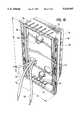
- FIG. 2is a rear perspective view of an embodiment of the modular timer of FIG. 1, having a rear extending interference member, shown with a front perspective view of a single plate end finishing element;
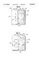
- FIG. 3is a partial sectional view of the modular timer of FIG. 1, showing the single plate and finishing element mounted thereto;
- FIG. 4is a partial cross-sectional view of the modular timer and finishing element of FIG. 3;
- FIG. 5is a front plan view of the modular timer illustrated with a double switch plate end finishing element
- FIG. 6is a front plan view of the modular timer illustrated with a double outlet plate end finishing element
- FIG. 7is a front plan view of the modular timer illustrated with a pair of single plate edge finishing elemental
- FIG. 8is an alternate embodiment of an end finishing element for use with an associated single electrical switch
- FIG. 9is another end finishing element of the embodiment of FIG. 8 for use with an associated double outlet.
- FIG. 10is an alternate embodiment of the modular timer similar to FIG. 1, without an interference member extending from the rear of the timer housing.
- FIG. 1there is illustrated an electronic timer switch 10 having an elongated housing 12.
- the switch 10is shown with reference to an associated, standard, double-ganged electrical connector box B having an exemplary standard electrical switch S located therein.
- the housing 12has first and second spaced apart finished edges 14, 16 along a predetermined width dimension W and first and second spaced apart unfinished mating surfaces or receiver edges 18, 20 along a predetermined height dimension H (see FIG. 2).
- the illustrated timer 10includes an electrical timer circuit 22 internal thereto, illustrated in phantom lines. As shown, the timer 10 includes a hinged door 24 which permits access to various switches 26 for, for example, setting the time of day, and presetting the desired times for switching on and off an associated electrical appliance or load, such as a lamp.
- the timer 10may also include a switch 28 for manually overriding the preset times for switching the associated appliance on and off. Other switches located on the timer 10 may include a power switch 30 and a reset switch 32. In addition, the timer 10 may also include an indicator 34 to indicate the time of day or the mode of operation of the timer. Preferably the door 24 includes an indicator opening or window 36 so that the indicator can be viewed with the door 24 in the closed position.
- the height dimension H of the housing 12is predetermined to be substantially consistent with the height dimension of a standard wall switch or electrical receptacle cover plate. In one known standard wall switch plate design, this dimension is about 41/2 inches. It is to be understood that the height dimension H of the housing 12 can be made to match any size wall switch or receptacle cover plate.
- the switch 10further includes a plurality of edge finishing elements or end termination elements 38 which are releasably engageable with the unfinished receiver edges 18, 20.
- the edge finishing elements 38various types of which are more fully described herein, have engaging surfaces 40 to facilitate secure yet releasable engagement between the finishing element 38 and the receiver edges 18, 20.
- the receiver edge 18, 20includes at least one outwardly extending locking member 42, and the finishing element 38 includes a complimentary locking notch 44.
- This configurationcan, of course, be reversed, with the locking member 42 extending from the finishing element 38 and the locking notch 44 being formed in the receiver edge 18, 20.
- each of the receiver edges 18, 20 and the finishing elements 38may include a plurality of the same of complimentary locking members 42 and notches 44, with the understanding that the other of the receiver edges 18, 20 and the finishing elements 38 includes a complementary set of locking elements 42, 44.
- the locking members 42 and notches 44are configured such that the ends of the finishing element 46 align with a line L formed by the finished edges 14, 16 of the housing 12 when the finishing element 38 is mounted to the timer housing 12.
- the edge finishing elements 38mount to the housing 12 by engaging the locking members 42 and notches 44 and rotating the element 38 forwardly, about an axis A (see FIG. 1) along the receiver edge 18, 20, until the finishing element 38 is flush with the housing 12. Conversely, the finishing elements 38 release from the receiver edges 18, 20 by rotating the finishing elements 38 rearwardly of the timer switch 10, about the axis A and disengaging the locking members 42 from the notches 44.
- This configurationpermits ready assembly of the finishing elements 38 to the timer switch 10 by a simple hook and rotate procedure.
- such a configurationalso prevents inadvertent removal of the finishing elements 38 from the timer switch 10 when the switch 10 is mounted to a wall.
- the finishing elements 38which are flush with the wall, cannot be rotated rearwardly to release from the housing 12.
- the finishing elements 38can be mounted to the timer housing 12 such that the assembly has a width substantially equal to the width of a single wall switch cover plate.
- assemblies 110, 112such as those illustrated in FIGS. 5 and 6 can be configured to have a width equal to that of a multiple-ganged (e.g., a double or triple width) wall switch cover plate.
- the multiple-ganged wall switch cover plate 110, 112can accommodate any number of appliances such the exemplary standard light switch S illustrated in FIG. 1, dimmer switches, "designer" switches, electrical receptacle outlets and the like.
- the timer switch 10defines a pair of apertures 48, as shown in FIGS. 1 and 9, through which fasteners, such as metal screws 50, can be inserted to mount the switch 10 to an associated, standard electrical connector box B.
- the timer 10is connected, by wires 52, to the wires W for the appropriate electrical circuit which is to be controlled (not shown) as the circuit wires W extend into the box B.
- the timer 10is then fastened to the box B, as described above.
- the finishing element 238has a backing plate 240 which extends between and connects a pair of mating surfaces 242 which are adjacent to the finished edges 244.
- the switch housing 12mounts to the backing plate 240 and mating surface 242 to position the finished edges 244 along the height dimension H of the housing 12.
- This embodimentmay further include an interference member 246 extending rearwardly from a rear surface 248 of the timer switch 10.
- the backing plate 240may have a corresponding opening 250 therein for receiving the interference member 246. This configuration prevents use of the timer switch 10 with a cover plate which is not intended for use with the switch 10, such as a standard wall switch cover plate.
- the finishing elements 238 of this embodimentcan include any combination of openings 252 for accommodating appliances such as standard light switches, dimmer switches, "designer” switches, electrical receptacle outlets and the like.
- the backing plate 240may include apertures 254 formed therein which are in alignment with the apertures 48 of the switch 10 to permit mounting to a standard electrical connector box B.
- the finishing elements 38, 238 of the present inventionare symmetrical relative to the timer housing 12. That is, the receiver edges 18, 20 of the housing 12 and the engaging surfaces 40 of the finishing elements 38 are configured to permit any of the finishing elements 38 to be mounted to either side of the housing 12. This necessarily reduces the overall number of parts in that the elements 38 are interchangeable as they mount to the housing 12. This further facilitates installation of the timer 10 because specifically oriented finishing elements 38 are not needed.
- this configurationalso permits the timer housing 12 to be located at an end of or between any two finishing elements 38.
- Thiscan include an arrangement in which the housing 12 is mounted between, for example, two switch plate or receptacle elements 38, such as the elements 38 illustrated in FIGS. 5 and 6, as well as the single plate arrangement shown in FIG. 7.
- finishing elements 38, 238, and the finishing elements 38, 238can be provided in sizes to accommodate any number of appliances and to fit single as well as multiple-ganged electrical box connectors, which combinations and sizes are intended to be within the scope of the present invention.
Landscapes
- Switch Cases, Indication, And Locking (AREA)
- Electric Clocks (AREA)
- Connection Or Junction Boxes (AREA)
Abstract
Description
Claims (8)
Priority Applications (4)
| Application Number | Priority Date | Filing Date | Title |
|---|---|---|---|
| US08/513,443US5638947A (en) | 1995-08-10 | 1995-08-10 | Modular timer having multiple finished extension members |
| CN96109386ACN1147712A (en) | 1995-08-10 | 1996-08-09 | Modular timer having multiple finished extension members |
| JP8210984AJPH09204863A (en) | 1995-08-10 | 1996-08-09 | Modular timer with multi-step finish expansion member |
| MXPA/A/1996/003297AMXPA96003297A (en) | 1995-08-10 | 1996-08-09 | Modular chronometer that has multiple members of extension ends |
Applications Claiming Priority (1)
| Application Number | Priority Date | Filing Date | Title |
|---|---|---|---|
| US08/513,443US5638947A (en) | 1995-08-10 | 1995-08-10 | Modular timer having multiple finished extension members |
Publications (1)
| Publication Number | Publication Date |
|---|---|
| US5638947Atrue US5638947A (en) | 1997-06-17 |
Family
ID=24043290
Family Applications (1)
| Application Number | Title | Priority Date | Filing Date |
|---|---|---|---|
| US08/513,443Expired - Fee RelatedUS5638947A (en) | 1995-08-10 | 1995-08-10 | Modular timer having multiple finished extension members |
Country Status (3)
| Country | Link |
|---|---|
| US (1) | US5638947A (en) |
| JP (1) | JPH09204863A (en) |
| CN (1) | CN1147712A (en) |
Cited By (11)
| Publication number | Priority date | Publication date | Assignee | Title |
|---|---|---|---|---|
| US20050152306A1 (en)* | 2004-01-12 | 2005-07-14 | Vincent Bonnassieux | Wi-Fi access point device and system |
| US20050152323A1 (en)* | 2004-01-12 | 2005-07-14 | Vincent Bonnassieux | Plug-in Wi-Fi access point device and system |
| US20060144609A1 (en)* | 2004-12-30 | 2006-07-06 | Ortronics, Inc. | Discrete access point mounting system |
| US20060178042A1 (en)* | 2005-02-04 | 2006-08-10 | Honeywell International, Inc. | Wall plate adapter for coupling home network control signals to AC power wiring |
| GB2435127A (en)* | 2006-02-09 | 2007-08-15 | David Edmund Gravelle | A decorative surround for a switch |
| US20070254530A1 (en)* | 2006-05-01 | 2007-11-01 | Martich Mark E | Plug assembly including integral printed circuit board |
| US20070263855A1 (en)* | 2006-05-01 | 2007-11-15 | Martich Mark E | Electrical receptacle with open corner region |
| US20070263856A1 (en)* | 2006-05-01 | 2007-11-15 | Kourosh Parsa | Wireless access point with temperature control system |
| US20090152085A1 (en)* | 2004-09-16 | 2009-06-18 | Shafi Al Dosari | Mechanical timer switch assembly |
| WO2009138730A1 (en)* | 2008-05-15 | 2009-11-19 | Logicor Limited | Electrical socket and method of use thereof |
| US20110314951A1 (en)* | 2010-06-25 | 2011-12-29 | Tetsuo Uchida | Apparatus |
Families Citing this family (3)
| Publication number | Priority date | Publication date | Assignee | Title |
|---|---|---|---|---|
| CN101710664B (en)* | 2009-12-05 | 2011-08-31 | 王建友 | Time control wall socket |
| CN111770658B (en)* | 2020-07-09 | 2021-07-09 | 宁波公牛电器有限公司 | Electrical module frame and electrical device |
| CN112687495B (en)* | 2020-12-18 | 2022-07-26 | 宁波斯佳电器有限公司 | Shock-proof type detachable microwave oven timer with high adaptability |
Citations (11)
| Publication number | Priority date | Publication date | Assignee | Title |
|---|---|---|---|---|
| US131848A (en)* | 1872-10-01 | Improvement in fly-traps | ||
| US3432611A (en)* | 1966-06-30 | 1969-03-11 | Sierra Electric Corp | Electrical device moduline |
| US3735020A (en)* | 1971-09-29 | 1973-05-22 | Lutron Electronics Co | Heat sink wall plate with off-center mounting openings |
| US3864512A (en)* | 1974-02-13 | 1975-02-04 | Theodore B Meadow | Cover for utility outlet |
| US3889132A (en)* | 1974-02-21 | 1975-06-10 | Robert L Vreeland | Timer assembly for outside light |
| US3939361A (en)* | 1974-05-09 | 1976-02-17 | Arthur D. Little, Inc. | Electronic timer switch |
| DE2452173A1 (en)* | 1974-11-02 | 1976-05-06 | Giersiepen Eltech Ind | Cover plates for electrical installation elements - are designed so that they can interlock for assembly into multiple combinations of individual units |
| US3979601A (en)* | 1975-02-10 | 1976-09-07 | Franklin Robert C | Combination dimmer and timer switch mechanism |
| US4151515A (en)* | 1977-11-11 | 1979-04-24 | Hutec Corporation | Load control apparatus |
| US4163882A (en)* | 1977-12-05 | 1979-08-07 | Baslow Floyd M | Adapter for standard electrical wall fixtures |
| USD255113S (en) | 1977-11-11 | 1980-05-27 | Hutec Corporation | Electric power load controller |
- 1995
- 1995-08-10USUS08/513,443patent/US5638947A/ennot_activeExpired - Fee Related
- 1996
- 1996-08-09JPJP8210984Apatent/JPH09204863A/enactivePending
- 1996-08-09CNCN96109386Apatent/CN1147712A/enactivePending
Patent Citations (11)
| Publication number | Priority date | Publication date | Assignee | Title |
|---|---|---|---|---|
| US131848A (en)* | 1872-10-01 | Improvement in fly-traps | ||
| US3432611A (en)* | 1966-06-30 | 1969-03-11 | Sierra Electric Corp | Electrical device moduline |
| US3735020A (en)* | 1971-09-29 | 1973-05-22 | Lutron Electronics Co | Heat sink wall plate with off-center mounting openings |
| US3864512A (en)* | 1974-02-13 | 1975-02-04 | Theodore B Meadow | Cover for utility outlet |
| US3889132A (en)* | 1974-02-21 | 1975-06-10 | Robert L Vreeland | Timer assembly for outside light |
| US3939361A (en)* | 1974-05-09 | 1976-02-17 | Arthur D. Little, Inc. | Electronic timer switch |
| DE2452173A1 (en)* | 1974-11-02 | 1976-05-06 | Giersiepen Eltech Ind | Cover plates for electrical installation elements - are designed so that they can interlock for assembly into multiple combinations of individual units |
| US3979601A (en)* | 1975-02-10 | 1976-09-07 | Franklin Robert C | Combination dimmer and timer switch mechanism |
| US4151515A (en)* | 1977-11-11 | 1979-04-24 | Hutec Corporation | Load control apparatus |
| USD255113S (en) | 1977-11-11 | 1980-05-27 | Hutec Corporation | Electric power load controller |
| US4163882A (en)* | 1977-12-05 | 1979-08-07 | Baslow Floyd M | Adapter for standard electrical wall fixtures |
Non-Patent Citations (1)
| Title |
|---|
| A set of 4 photographs of a switch plate and attendent accessories.* |
Cited By (21)
| Publication number | Priority date | Publication date | Assignee | Title |
|---|---|---|---|---|
| US20050152323A1 (en)* | 2004-01-12 | 2005-07-14 | Vincent Bonnassieux | Plug-in Wi-Fi access point device and system |
| US20110056067A1 (en)* | 2004-01-12 | 2011-03-10 | Ortronics, Inc. | Wi-Fi Access Point Device and System |
| US7785138B2 (en) | 2004-01-12 | 2010-08-31 | Ortronics, Inc. | Wireless access point installation on an outlet box |
| US20050152306A1 (en)* | 2004-01-12 | 2005-07-14 | Vincent Bonnassieux | Wi-Fi access point device and system |
| US20090152085A1 (en)* | 2004-09-16 | 2009-06-18 | Shafi Al Dosari | Mechanical timer switch assembly |
| US7579565B2 (en)* | 2004-09-16 | 2009-08-25 | Shafi Al Dosari | Mechanical timer switch assembly |
| US20060144609A1 (en)* | 2004-12-30 | 2006-07-06 | Ortronics, Inc. | Discrete access point mounting system |
| WO2006073932A3 (en)* | 2004-12-30 | 2006-11-02 | Ortronics Inc | Discrete access point mounting system |
| US20060178042A1 (en)* | 2005-02-04 | 2006-08-10 | Honeywell International, Inc. | Wall plate adapter for coupling home network control signals to AC power wiring |
| US7247793B2 (en)* | 2005-02-04 | 2007-07-24 | Honeywell International Inc. | Wall plate adapter for coupling home network control signals to AC power wiring |
| GB2435127A (en)* | 2006-02-09 | 2007-08-15 | David Edmund Gravelle | A decorative surround for a switch |
| US7322860B2 (en) | 2006-05-01 | 2008-01-29 | Ortronics, Inc. | Plug assembly including integral printed circuit board |
| US20070263856A1 (en)* | 2006-05-01 | 2007-11-15 | Kourosh Parsa | Wireless access point with temperature control system |
| US7734038B2 (en) | 2006-05-01 | 2010-06-08 | Ortronics, Inc. | Electrical receptacle with open corner region |
| US7747272B2 (en) | 2006-05-01 | 2010-06-29 | Ortronics, Inc. | Wireless access point with temperature control system |
| US20070263855A1 (en)* | 2006-05-01 | 2007-11-15 | Martich Mark E | Electrical receptacle with open corner region |
| US20070254530A1 (en)* | 2006-05-01 | 2007-11-01 | Martich Mark E | Plug assembly including integral printed circuit board |
| WO2009138730A1 (en)* | 2008-05-15 | 2009-11-19 | Logicor Limited | Electrical socket and method of use thereof |
| US20110097926A1 (en)* | 2008-05-15 | 2011-04-28 | Logicor Limited | Electrical socket and method of use thereof |
| US20110314951A1 (en)* | 2010-06-25 | 2011-12-29 | Tetsuo Uchida | Apparatus |
| US8829374B2 (en)* | 2010-06-25 | 2014-09-09 | Fuji Xerox Co., Ltd. | Apparatus |
Also Published As
| Publication number | Publication date |
|---|---|
| MX9603297A (en) | 1997-07-31 |
| JPH09204863A (en) | 1997-08-05 |
| CN1147712A (en) | 1997-04-16 |
Similar Documents
| Publication | Publication Date | Title |
|---|---|---|
| US5638947A (en) | Modular timer having multiple finished extension members | |
| US5744750A (en) | Modular electrical connector box | |
| US5562488A (en) | Modular outlet assembly | |
| US7074078B2 (en) | Receptacle-mounted cover plate to hide electrical socket face | |
| US5651696A (en) | CEBUS tap point unit | |
| US4636914A (en) | Outlet box with removable self-contained device | |
| CA1215153A (en) | Multiple outlet receptacle | |
| CA2401436C (en) | Quick connecting universal electrical box and wiring system | |
| US5135411A (en) | Multiple outlet receptacle and mountings therefor | |
| US6051785A (en) | Electrical wiring switch and receptacle leveling/protector plate | |
| US4631649A (en) | Plug-in emergency light fixture | |
| US5223673A (en) | Modular electrical outlet assembly | |
| US4774641A (en) | Illuminated electric outlet cover plate | |
| EP0746075B1 (en) | Electrical receptacle cover having an integrally formed detachable fastening nut | |
| US4778399A (en) | Multi-service electrical outlet module | |
| EP0391713A2 (en) | Trunking assembly | |
| AU2001233549A1 (en) | Quick connecting universal electrical box and wiring system | |
| US5823821A (en) | Apparatus for securing an electrical outlet to an outlet box having stripped threads | |
| GB2194395A (en) | Mounting electric accessories | |
| CA2051869A1 (en) | Multiple outlet locking receptacle | |
| US6010361A (en) | Electrical unit for plugging into a mount, in particular a self-contained emergency lighting unit | |
| MXPA96003297A (en) | Modular chronometer that has multiple members of extension ends | |
| US3744004A (en) | Press fit outlet junction box with means for detachably interlocking with electrical cord | |
| WO2020231465A1 (en) | Screw less cover plate for electrical fixtures | |
| GB2345806A (en) | Mounting an electrical accessory into an accesory box |
Legal Events
| Date | Code | Title | Description |
|---|---|---|---|
| AS | Assignment | Owner name:BRK BRANDS, INC., ILLINOIS Free format text:ASSIGNMENT OF ASSIGNORS INTEREST;ASSIGNOR:FENNE, KENNETH R.;REEL/FRAME:007684/0553 Effective date:19950721 | |
| AS | Assignment | Owner name:FIRST NATIONAL BANK OF CHICAGO, THE, ILLINOIS Free format text:ASSIGNMENT OF ASSIGNORS INTEREST;ASSIGNOR:BRK BRANDS, INC.;REEL/FRAME:008321/0141 Effective date:19960903 | |
| AS | Assignment | Owner name:NATIONSBANK, N.A., AS AGENT, MARYLAND Free format text:SECURITY AGREEMENT;ASSIGNOR:BRK BRANDS, INC.;REEL/FRAME:008545/0585 Effective date:19970514 | |
| AS | Assignment | Owner name:FIRST UNION NATIONAL BANK, AS ADMINISTRATIVE AGENT Free format text:SECURITY AGREEMENT;ASSIGNORS:DDG I, INC.;OP II, INC.;GHI I, INC.;AND OTHERS;REEL/FRAME:010506/0173 Effective date:19980710 | |
| AS | Assignment | Owner name:FIRST UNION NATIONAL BANK, AS ADMINISTRATIVE AGENT Free format text:SECURITY INTEREST;ASSIGNOR:BRK BRANDS, INC. (DE CORPORATION);REEL/FRAME:011111/0190 Effective date:20000929 | |
| FPAY | Fee payment | Year of fee payment:4 | |
| AS | Assignment | Owner name:BRK BRANDS, INC., ILLINOIS Free format text:TERMINATION AND RELEASE OF SECURITY INTEREST;ASSIGNOR:WACHOVIA BANK, NATIONAL ASSOCIATION, FORMERLY FIRST UNION NATIONAL BANK;REEL/FRAME:014015/0215 Effective date:20021213 | |
| AS | Assignment | Owner name:GENERAL ELECTRIC CAPITAL CORPORATION, GEORGIA Free format text:INTELLECTUAL PROPERTY SECURITY AGREEMENT;ASSIGNORS:COLEMAN COMPANY, INC., THE;COLEMAN POWERMATE, INC.;BRK BRANDS, INC.;AND OTHERS;REEL/FRAME:014027/0767 Effective date:20021213 | |
| REMI | Maintenance fee reminder mailed | ||
| LAPS | Lapse for failure to pay maintenance fees | ||
| STCH | Information on status: patent discontinuation | Free format text:PATENT EXPIRED DUE TO NONPAYMENT OF MAINTENANCE FEES UNDER 37 CFR 1.362 | |
| FP | Lapsed due to failure to pay maintenance fee | Effective date:20050617 |